EP1738775A1 - Device for reducing the number of bacterial germs in a fluid - Google Patents
Device for reducing the number of bacterial germs in a fluid Download PDFInfo
- Publication number
- EP1738775A1 EP1738775A1 EP06300518A EP06300518A EP1738775A1 EP 1738775 A1 EP1738775 A1 EP 1738775A1 EP 06300518 A EP06300518 A EP 06300518A EP 06300518 A EP06300518 A EP 06300518A EP 1738775 A1 EP1738775 A1 EP 1738775A1
- Authority
- EP
- European Patent Office
- Prior art keywords
- fluid
- ultrasonic wave
- generating
- outlet
- ultrasonic
- Prior art date
- Legal status (The legal status is an assumption and is not a legal conclusion. Google has not performed a legal analysis and makes no representation as to the accuracy of the status listed.)
- Granted
Links
Images

Classifications
-
- A—HUMAN NECESSITIES
- A61—MEDICAL OR VETERINARY SCIENCE; HYGIENE
- A61L—METHODS OR APPARATUS FOR STERILISING MATERIALS OR OBJECTS IN GENERAL; DISINFECTION, STERILISATION OR DEODORISATION OF AIR; CHEMICAL ASPECTS OF BANDAGES, DRESSINGS, ABSORBENT PADS OR SURGICAL ARTICLES; MATERIALS FOR BANDAGES, DRESSINGS, ABSORBENT PADS OR SURGICAL ARTICLES
- A61L2/00—Methods or apparatus for disinfecting or sterilising materials or objects other than foodstuffs or contact lenses; Accessories therefor
- A61L2/02—Methods or apparatus for disinfecting or sterilising materials or objects other than foodstuffs or contact lenses; Accessories therefor using physical phenomena
- A61L2/025—Ultrasonics
-
- A—HUMAN NECESSITIES
- A61—MEDICAL OR VETERINARY SCIENCE; HYGIENE
- A61L—METHODS OR APPARATUS FOR STERILISING MATERIALS OR OBJECTS IN GENERAL; DISINFECTION, STERILISATION OR DEODORISATION OF AIR; CHEMICAL ASPECTS OF BANDAGES, DRESSINGS, ABSORBENT PADS OR SURGICAL ARTICLES; MATERIALS FOR BANDAGES, DRESSINGS, ABSORBENT PADS OR SURGICAL ARTICLES
- A61L9/00—Disinfection, sterilisation or deodorisation of air
- A61L9/16—Disinfection, sterilisation or deodorisation of air using physical phenomena
-
- C—CHEMISTRY; METALLURGY
- C02—TREATMENT OF WATER, WASTE WATER, SEWAGE, OR SLUDGE
- C02F—TREATMENT OF WATER, WASTE WATER, SEWAGE, OR SLUDGE
- C02F1/00—Treatment of water, waste water, or sewage
- C02F1/34—Treatment of water, waste water, or sewage with mechanical oscillations
- C02F1/36—Treatment of water, waste water, or sewage with mechanical oscillations ultrasonic vibrations
-
- C—CHEMISTRY; METALLURGY
- C02—TREATMENT OF WATER, WASTE WATER, SEWAGE, OR SLUDGE
- C02F—TREATMENT OF WATER, WASTE WATER, SEWAGE, OR SLUDGE
- C02F1/00—Treatment of water, waste water, or sewage
- C02F1/48—Treatment of water, waste water, or sewage with magnetic or electric fields
-
- C—CHEMISTRY; METALLURGY
- C02—TREATMENT OF WATER, WASTE WATER, SEWAGE, OR SLUDGE
- C02F—TREATMENT OF WATER, WASTE WATER, SEWAGE, OR SLUDGE
- C02F2201/00—Apparatus for treatment of water, waste water or sewage
- C02F2201/48—Devices for applying magnetic or electric fields
- C02F2201/483—Devices for applying magnetic or electric fields using coils
Definitions
- the present invention relates to a device for the treatment of fluids, in particular the treatment of water or gases, using a magnetic field and ultrasonic waves, in order to reduce the amount of pathogens present in said fluid.
- Pathogens potentially harmful to living things include bacteria, viruses, fungi, molds and yeasts.
- pathogens proliferate rapidly depending on the media in which they are present such as liquids or aerosols consisting of microdroplets of liquid dispersed in a gas. These pathogens also proliferate rapidly as a function of temperature.
- Prokaryotic cells among which bacteria are counted, are small, generally of the order of 0.4 ⁇ m to 1 ⁇ m in diameter. These single cells are limited by an envelope called a plasma membrane with a single chromosome formed of a DNA molecule in the cytoplasm of the bacterium. The replication and transcription of the genetic material of bacteria takes place directly in the cytoplasm.
- viruses are entities of very small size, of the order of 0.001 to 0.1 microns including, as genetic material, short DNA or RNA sequences, protected within an essentially proteinaceous protective envelope , the capsid.
- One of the ways to destroy pathogens is to weaken, or destroy, plasma membranes or capsids, and more generally the envelopes protecting the genetic material of pathogens.
- the inventor has discovered that this operation of destroying the protective envelope of the genetic material of the pathogens, within a fluid, can be achieved by emitting, within the fluid, electromagnetic waves and multiplexed ultrasound waves.
- the cytoplasm no longer delimits a viable environment for the bacterium, and the bacterial elements become ineffective.
- the bacteria becomes non-pathogenic.
- the pathogens subjected to electromagnetic waves and multiplexed ultrasonic waves within the fluid carrying them become non-pathogenic agents, no longer any biological function being able to be ensured. These agents then become simple aggregates of non-pathogenic macromolecules.
- the inventor has therefore developed a device for treating a fluid, intended to reduce the amount of pathogens in said fluid.
- the ultrasonic wave generation means are arranged around the fluid treatment chamber, so that the ultrasound waves emitted have a common point of convergence on the longitudinal main axis.
- the inlet and outlet conduits of the fluid comprise supports that hold the ultrasonic wave reflector along the longitudinal main axis of said device.
- the ultrasonic wave reflector preferably in the form of a cylinder, is made of ferrite so as to promote the reflection of the waves towards the part of the treatment chamber traversed by the fluid.
- ferrite is meant a magnetic oxide, such as manganese-zinc ferrites or nickel-zinc ferrites.
- ultrasonic waves is intended to mean high frequency acoustic waves whose operating range is between 10 kHz and 20 MHz, preferably greater than 10 kHz, or better still greater than 20 kHz. .
- the operating range of frequencies will preferably be between 1 MHz and 10 MHz, the power setting being between 30 and 200 watts.
- the ultrasonic waves are emitted at a speed of the order of 1480 m / s in the water.
- the wavelength varies, for a speed of 1480 m / s, from 0.3 mm to 1.5 mm, which corresponds respectively to frequencies of 5 MHz and 1 MHz.
- the ultrasound waves emitted have a direction preferably perpendicular to the longitudinal main axis of the device of the invention, therefore to the flow direction of the fluid flow, and pathogens within it.
- the direction of the fluid flow is coincident with the longitudinal main axis of the dipositif, and forms an angle of about 90 ° with the direction of the ultrasonic waves.
- the inventor believes that the described treatment device, promotes the formation of transverse waves with respect to the longitudinal main axis, and shear waves so that the direction of the vibration pathogens processed within the fluid is perpendicular to the direction of propagation of the ultrasonic wave.
- the ultrasonic wave generating means is in direct contact with the fluid to be treated.
- the ultrasonic wave generating means are disposed at the periphery of the fluid treatment chamber, so that the ultrasonic waves thus produced are emitted towards the ultrasonic wave reflector and then reflected by said reflector.
- the ultrasound wave generating means comprising a transmitter, generates an ultrasonic wave which passes through the fluid flow within the treatment chamber, a first time in the direction of of the wave reflector ultrasound, then is reflected by the latter. The wave then traverses a second time the fluid flow within the treatment chamber, and returns to a receiver in the vicinity of the ultrasonic wave generating means.
- a receiver makes it possible to adapt the power and the emission frequency as a function of the path of the wave and of the efficiency sought for the destruction of the pathogens.
- the device of the invention comprises at least two ultrasonic transducers carried by the treatment chamber in diametrically opposed positions.
- each of the means generating an electromagnetic field, within said inlet and outlet conduits of the fluid has a magnetic field component of 1 to 5 Tesla, preferably 1 to 2 Tesla.
- each of the means generating an electromagnetic field, within said inlet and outlet conduits of the fluid is an electromagnetic coil.
- said fluid passing through the device according to the invention is a gas or a liquid, for example selected from air, water vapor or water.
- said pathogen is selected from a bacterium, a virus or a fungus.
- the invention also relates to a method for reducing the quantity of pathogens in a fluid stream, comprising subjecting in a treatment chamber in which the flow flows along a longitudinal axis, a fluid flow to ultrasonic waves propagating preferably perpendicular to the longitudinal flow axis of the flux, under the influence of a magnetic field.
- the treatment chamber (1) may have any shape, but is preferably cylindrical as will become more clearly apparent in FIG. 3.
- the ultrasonic wave reflector (4) comprising magnetic ferrite has a central portion (5). ), which becomes magnetic under the influence of the coils (3) and (3 ').
- the fluid inlet (2) and outlet (2 ') ducts comprise supports (20) which hold the ultrasonic wave reflector (4) along the longitudinal main axis of the device (400).
- each of the means generating an electromagnetic field preferably coils electromagnetic field
- Such magnetic field values allow to create an area conducive to reducing the amount of pathogens within said fluid and in particular in the area (7) of fluid circulation.
- the presence of the ultrasonic wave reflector (4) makes it possible to induce permanent magnetization.
- the ultrasonic waves produced in the treatment chamber are accelerated which promotes the destruction of pathogens.
- the coils (3 and 3 ') which generate a magnetic field comprise power supply means (31).
- the device (400) as shown in Figure 1 comprises at least two ultrasonic transducers (9) carried by the treatment chamber (1) in diametrically opposed positions.
- the ultrasonic wave generating means (8) which comprises an ultrasonic transducer (9), generate ultrasonic waves which pass through the fluid flow within the treatment chamber (1), towards the ultrasonic wave reflector (4), and these ultrasonic waves are reflected by the latter. The ultrasonic waves then pass through the fluid flow a second time within the treatment chamber (1) and return to a receiver located near the transducer (9).
- the waves emitted in bundles (11) pass through the fluid circulation zone (7) to be reflected according to the orientation (12) after reflection on the ultrasonic wave reflector (4); the intermediate zone (13) having a magnetic influence and strong vibrations induced by the ultrasonic waves. Therefore, it is in the intermediate zone (13) that the pathogens will be destroyed.
- the arrangement of the concentric transducers (8) makes it possible to have a point of convergence of the ultrasonic waves on the longitudinal principal axis of the device (400), and more particularly on the reflector d ultrasonic waves (4).
- the path of the emitted ultrasonic waves is represented by the indices (11) (incident waves), and (12) (reflected waves).
- the magnetic central (131) and peripheral magnetic (132) zones in which the ultrasonic and magnetic waves reach high velocities result in the destruction of pathogens and eliminate any risk of biofilm formation.
- the longitudinal wave (11) is reflected on the ultrasonic wave reflector (4) at an angle (200) to the vertical, its reflection being at a lower angle (201). ) with respect to a planar display (203).
- a transverse wave also exists (202) favoring shearing obliquely with respect to the axis of circulation of the fluid.
- the emission of the wave (11) represents an amplitude (304) for a characteristic wavelength of the frequency adopted setting.
- the adjustment of the power and the frequency of emission of the ultrasonic waves will be done by quantifying the emission times (302) of the reflected wave (303).
- the approximation of the rate of the next emission (301) makes it possible to modulate and multiplex these ultrasonic waves for a better efficiency of the device.
- FIG. 7 represents the spatial visualization of the entanglement of the incident (11) and reflected (12) waves and shows the shearing effect induced by the multiplexing of the waves.
- the settings can be optimized for the emission of the initial wave between 0.1 m / s and 5 m / s depending on the flow rate and the flow rate of the fluid to be decontaminated so that during the time of in the device (400), the number of transmitted wave trains is between 10 and 30 or more, so as to cause the vibrations and shear waves necessary to destroy the pathogens contained in the fluid to be treated.
- the device (400) described above equips a cooling tower.
- the cooling towers being known to those skilled in the art these will not be described in detail below.
- the cooling towers are generally rectangular and comprise an envelope (100) which has at its lower part a water tank (101) which circulates by a pump (104) to be injected at the top (105) and then run off on oblique plates (103) for cooling the air by mixing.
- An airflow (107) initiated by a fan (102) releases air to the atmosphere at (108). If bacterial contamination occurs in the refrigeration tower, the bacterial contamination will be dispersed by the relative humidity released to the outside by the flow (108) thus causing contamination around the cooling tower.
- the use of the device (400) on the water injection recycling in (115) makes it possible to reduce this risk.
Landscapes
- Health & Medical Sciences (AREA)
- Life Sciences & Earth Sciences (AREA)
- Engineering & Computer Science (AREA)
- Epidemiology (AREA)
- Animal Behavior & Ethology (AREA)
- General Health & Medical Sciences (AREA)
- Public Health (AREA)
- Veterinary Medicine (AREA)
- Environmental & Geological Engineering (AREA)
- Hydrology & Water Resources (AREA)
- Mechanical Engineering (AREA)
- Water Supply & Treatment (AREA)
- Chemical & Material Sciences (AREA)
- Organic Chemistry (AREA)
- Apparatus For Disinfection Or Sterilisation (AREA)
- Physical Water Treatments (AREA)
- Separation Using Semi-Permeable Membranes (AREA)
- Chemical Or Physical Treatment Of Fibers (AREA)
- External Artificial Organs (AREA)
- Immobilizing And Processing Of Enzymes And Microorganisms (AREA)
- Medicines Containing Material From Animals Or Micro-Organisms (AREA)
- Polysaccharides And Polysaccharide Derivatives (AREA)
- Medicines Containing Plant Substances (AREA)
Abstract
Description
La présente invention concerne un dispositif destiné au traitement des fluides, en particulier au traitement des eaux ou des gaz, mettant en oeuvre un champ magnétique et des ondes ultrasonores, dans le but de réduire la quantité d'agents pathogènes présents au sein dudit fluide.The present invention relates to a device for the treatment of fluids, in particular the treatment of water or gases, using a magnetic field and ultrasonic waves, in order to reduce the amount of pathogens present in said fluid.
La présence, dans l'atmosphère, et/ou les liquides, tels que l'eau, d'une concentration importante en agents pathogènes peut entraîner des nuisances importantes pour les êtres vivants, telles que des maladies.The presence in the atmosphere and / or liquids, such as water, of a high concentration of pathogens can cause significant harm to living things, such as diseases.
Parmi les agents pathogènes, potentiellement dangereux pour les êtres vivants, on compte les bactéries, les virus, les champignons, ou encore les moisissures et les levures.Pathogens potentially harmful to living things include bacteria, viruses, fungi, molds and yeasts.
Ces agents pathogènes prolifèrent rapidement en fonction des milieux dans lesquels ils sont présents tels que les liquides ou les aérosols constitués de microgouttelettes de liquide dispersées dans un gaz. Ces agents pathogènes prolifèrent également rapidement en fonction de la température.These pathogens proliferate rapidly depending on the media in which they are present such as liquids or aerosols consisting of microdroplets of liquid dispersed in a gas. These pathogens also proliferate rapidly as a function of temperature.
Les cellules procaryotes, parmi lesquelles on compte les bactéries, sont de petite taille, généralement de l'ordre de 0,4 µm à 1 µm de diamètre. Ces cellules simples sont limitées par une enveloppe que l'on appelle membrane plasmique comportant un chromosome unique formé d'une molécule d'ADN dans le cytoplasme de la bactérie. La réplication et la transcription du matériel génétique des bactéries s'effectue directement dans le cytoplasme.Prokaryotic cells, among which bacteria are counted, are small, generally of the order of 0.4 μm to 1 μm in diameter. These single cells are limited by an envelope called a plasma membrane with a single chromosome formed of a DNA molecule in the cytoplasm of the bacterium. The replication and transcription of the genetic material of bacteria takes place directly in the cytoplasm.
Parmi les agents pathogènes qui peuvent être transportés par les gaz et les liquides, on compte également des acaryotes, et notamment des virus. Les virus sont des entités de très petite taille, de l'ordre de 0,001 à 0,1 µm comprenant, à titre de matériel génétique, de courtes séquences d'ADN ou d'ARN, protégées au sein d'une enveloppe protectrice essentiellement protéique, la capside.Among the pathogens that can be carried by gases and liquids, there are also acaryotes, including viruses. Viruses are entities of very small size, of the order of 0.001 to 0.1 microns including, as genetic material, short DNA or RNA sequences, protected within an essentially proteinaceous protective envelope , the capsid.
La totalité de l'information génétique des agents pathogènes décrits ci-dessus est nécessaire au maintien de leurs fonctions métaboliques.All the genetic information of the pathogens described above is necessary to maintain their metabolic functions.
Compte tenu du danger des agents pathogènes pour l'homme et l'animal, il existe un besoin pour de nouveaux moyens de destruction des agents pathogènes au sein de flux de liquides ou de gaz.Given the danger of pathogens for humans and animals, there is a need for new means of destroying pathogens within liquid or gas streams.
L'un des moyens pour détruire des agents pathogènes est de fragiliser, ou de détruire, les membranes plasmiques ou les capsides, et de manière plus générale les enveloppes de protection du matériel génétique des agents pathogènes.One of the ways to destroy pathogens is to weaken, or destroy, plasma membranes or capsids, and more generally the envelopes protecting the genetic material of pathogens.
L'inventeur a découvert que cette opération de destruction de l'enveloppe de protection du matériel génétique des agents pathogènes, au sein d'un fluide, peut être réalisée en émettant, au sein du fluide, des ondes électromagnétiques et des ondes ultrasonores multiplexées.The inventor has discovered that this operation of destroying the protective envelope of the genetic material of the pathogens, within a fluid, can be achieved by emitting, within the fluid, electromagnetic waves and multiplexed ultrasound waves.
En affectant les membranes plasmiques des bactéries par exemple, le cytoplasme ne délimite plus un environnement viable pour la bactérie, et les éléments bactériens deviennent ainsi inopérants. Par ce mécanisme, la bactérie devient non pathogène. Ainsi, les agents pathogènes soumis, au sein du fluide qui les transporte, à des ondes électromagnétiques et à des ondes ultrasonores multiplexées, deviennent des agents non pathogènes, plus aucune fonction biologique ne pouvant être assurée. Ces agents deviennent alors de simples agrégats de macromolécules non pathogènes.By affecting the plasma membranes of bacteria for example, the cytoplasm no longer delimits a viable environment for the bacterium, and the bacterial elements become ineffective. By mechanism, the bacteria becomes non-pathogenic. Thus, the pathogens subjected to electromagnetic waves and multiplexed ultrasonic waves within the fluid carrying them become non-pathogenic agents, no longer any biological function being able to be ensured. These agents then become simple aggregates of non-pathogenic macromolecules.
L'inventeur a donc mis au point un dispositif de traitement d'un fluide, destiné à réduire la quantité d'agents pathogènes au sein dudit fluide.The inventor has therefore developed a device for treating a fluid, intended to reduce the amount of pathogens in said fluid.
Selon l'invention, ledit dispositif comprend, dans le sens d'écoulement dudit fluide, et selon un axe principal longitudinal :
- un conduit d'entrée du fluide équipé d'un moyen générant un champ électromagnétique au sein dudit conduit d'entrée,
- une enceinte définissant une cavité de traitement dudit fluide et comprenant au moins un moyen de génération d'ondes ultrasonores en direction du centre de ladite cavité,
- un conduit de sortie du fluide, équipé d'un moyen générant un champ électromagnétique au sein dudit conduit de sortie, et
- un réflecteur d'ondes ultrasonores, magnétisable, disposé selon l'axe principal longitudinal dudit dispositif, et comprenant une partie centrale située dans la cavité de l'enceinte et un prolongement situé dans chacun des conduits d'entrée et de sortie du fluide.
- a fluid inlet duct equipped with means generating an electromagnetic field within said inlet duct,
- an enclosure defining a treatment cavity of said fluid and comprising at least one means for generating ultrasonic waves towards the center of said cavity,
- a fluid outlet duct, equipped with means generating an electromagnetic field within said outlet duct, and
- a magnetizable ultrasonic wave reflector disposed along the longitudinal main axis of said device, and comprising a central portion located in the cavity of the chamber and an extension located in each of the inlet and outlet conduits of the fluid.
Les moyens de génération d'ondes ultrasonores sont disposés autour de l'enceinte de traitement du fluide, de sorte que les ondes ultrasonores émises possèdent un point de convergence commun sur l'axe principal longitudinal.The ultrasonic wave generation means are arranged around the fluid treatment chamber, so that the ultrasound waves emitted have a common point of convergence on the longitudinal main axis.
La présence, au niveau de l'axe principal longitudinal, d'un réflecteur d'ondes ultrasonores, permet une réflexion cylindrique ou « de paroi » des ondes ultrasonores. Ainsi, une concentration d'ondes importante est obtenue au sein de la cavité définie par l'enceinte de traitement. Cette concentration d'ondes importante au sein de l'enceinte de traitement, favorise la destruction des agents pathogènes véhiculés par le flux de fluide traversant l'enceinte de traitement.The presence, at the level of the longitudinal main axis, of an ultrasonic wave reflector allows a cylindrical or "wall" reflection of the ultrasonic waves. Thus, a significant wave concentration is obtained within the cavity defined by the treatment chamber. This large wave concentration within the treatment chamber, promotes the destruction of pathogens carried by the flow of fluid through the treatment chamber.
De préférence, les conduits d'entrée et de sortie du fluide comprennent des supports qui maintiennent le réflecteur d'ondes ultrasonores selon l'axe principal longitudinal dudit dispositif.Preferably, the inlet and outlet conduits of the fluid comprise supports that hold the ultrasonic wave reflector along the longitudinal main axis of said device.
Le réflecteur d'ondes ultrasonores, préférentiellement sous forme de cylindre, est en ferrite de sorte à favoriser la réflexion des ondes vers la partie de l'enceinte de traitement traversée par le fluide.The ultrasonic wave reflector, preferably in the form of a cylinder, is made of ferrite so as to promote the reflection of the waves towards the part of the treatment chamber traversed by the fluid.
Par ferrite, on entend un oxyde magnétique, tel que les ferrites de manganèse-zinc ou les ferrites nickel-zinc.By ferrite is meant a magnetic oxide, such as manganese-zinc ferrites or nickel-zinc ferrites.
Par « ondes ultrasonores » au sens de la présente invention, on entend, des ondes acoustiques de haute fréquence, dont la gamme d'exploitation se situe entre 10 kHz et 20 MHz, préférentiellement supérieures à 10 kHz, ou mieux encore supérieures à 20 kHz.For the purposes of the present invention, the term "ultrasonic waves" is intended to mean high frequency acoustic waves whose operating range is between 10 kHz and 20 MHz, preferably greater than 10 kHz, or better still greater than 20 kHz. .
A titre d'exemple, dans le domaine des fluides peu visqueux, la gamme d'exploitation des fréquences se situera préférentiellement entre 1 Mhz et 10 MHz, le réglage de la puissance s'effectuant entre 30 et 200 Watt.For example, in the field of low-viscosity fluids, the operating range of frequencies will preferably be between 1 MHz and 10 MHz, the power setting being between 30 and 200 watts.
Les ondes ultrasonores sont émises à une vitesse de l'ordre de 1480 m/s dans l'eau. Lorsque le flux de fluide traité est de l'eau, la longueur d'onde varie, pour une vitesse de 1480 m/s, de 0,3 mm à 1,5 mm, ce qui correspond respectivement à des fréquences de 5 MHz et 1 MHz.The ultrasonic waves are emitted at a speed of the order of 1480 m / s in the water. When the treated fluid flow is water, the wavelength varies, for a speed of 1480 m / s, from 0.3 mm to 1.5 mm, which corresponds respectively to frequencies of 5 MHz and 1 MHz.
Les ondes ultrasonores émises ont une direction de préférence perpendiculaire à l'axe principal longitudinal du dispositif de l'invention, donc à la direction d'écoulement du flux de fluide, et des agents pathogènes au sein de celui-ci. Ainsi, la direction du flux de fluide est confondue avec l'axe principal longitudinal du dipositif, et forme un angle d'environ 90° avec la direction des ondes ultrasonores.The ultrasound waves emitted have a direction preferably perpendicular to the longitudinal main axis of the device of the invention, therefore to the flow direction of the fluid flow, and pathogens within it. Thus, the direction of the fluid flow is coincident with the longitudinal main axis of the dipositif, and forms an angle of about 90 ° with the direction of the ultrasonic waves.
Sans vouloir être lié par une quelconque théorie, l'inventeur pense que le dispositif de traitement décrit, favorise la formation d'ondes transversales par rapport à l'axe principal longitudinal, et d'ondes de cisaillement de sorte que la direction de la vibration des agents pathogènes traités au sein du fluide est perpendiculaire à la direction de propagation de l'onde ultrasonore.Without wishing to be bound by any theory, the inventor believes that the described treatment device, promotes the formation of transverse waves with respect to the longitudinal main axis, and shear waves so that the direction of the vibration pathogens processed within the fluid is perpendicular to the direction of propagation of the ultrasonic wave.
Avantageusement, pour éviter les atténuations d'interface, le moyen de génération d'ondes ultrasonores est en contact direct avec le fluide à traiter.Advantageously, to avoid interface attenuation, the ultrasonic wave generating means is in direct contact with the fluid to be treated.
Avantageusement, les moyens de génération d'ondes ultrasonores sont disposés en périphérie de l'enceinte de traitement du fluide, de sorte que les ondes ultrasonores ainsi produites sont émises en direction du réflecteur d'ondes ultrasonores, puis réfléchies par ledit réflecteur.Advantageously, the ultrasonic wave generating means are disposed at the periphery of the fluid treatment chamber, so that the ultrasonic waves thus produced are emitted towards the ultrasonic wave reflector and then reflected by said reflector.
Ainsi, dans un mode de réalisation particulier de l'invention, le moyen de génération d'ondes ultrasonores, comprenant un émetteur, génère une onde ultrasonore qui traverse le flux de fluide au sein de l'enceinte de traitement, une première fois en direction du réflecteur d'ondes ultrasonores, puis est réfléchie par ce dernier. L'onde traverse ensuite une seconde fois le flux de fluide au sein de l'enceinte de traitement, et revient vers un récepteur à proximité du moyen de génération d'ondes ultrasonores. Un tel récepteur permet d'adapter la puissance et la fréquence d'émission en fonction du parcours de l'onde et de l'efficacité recherchée pour la destruction des agents pathogènes.Thus, in a particular embodiment of the invention, the ultrasound wave generating means, comprising a transmitter, generates an ultrasonic wave which passes through the fluid flow within the treatment chamber, a first time in the direction of of the wave reflector ultrasound, then is reflected by the latter. The wave then traverses a second time the fluid flow within the treatment chamber, and returns to a receiver in the vicinity of the ultrasonic wave generating means. Such a receiver makes it possible to adapt the power and the emission frequency as a function of the path of the wave and of the efficiency sought for the destruction of the pathogens.
De préférence, le dispositif de l'invention comprend au moins deux transducteurs ultrasonores portés par l'enceinte de traitement dans des positions diamétralement opposées.Preferably, the device of the invention comprises at least two ultrasonic transducers carried by the treatment chamber in diametrically opposed positions.
De préférence, chacun des moyens engendrant un champ électromagnétique, au sein desdits conduits d'entrée et de sortie du fluide, possède une composante de champ magnétique de 1 à 5 Tesla, de préférence, 1 à 2 Tesla.Preferably, each of the means generating an electromagnetic field, within said inlet and outlet conduits of the fluid, has a magnetic field component of 1 to 5 Tesla, preferably 1 to 2 Tesla.
Avantageusement, chacun des moyens engendrant un champ électromagnétique, au sein desdits conduits d'entrée et de sortie du fluide est une bobine électromagnétique.Advantageously, each of the means generating an electromagnetic field, within said inlet and outlet conduits of the fluid is an electromagnetic coil.
De préférence, ledit fluide traversant le dispositif selon l'invention est un gaz ou un liquide, par exemple choisi parmi l'air, la vapeur d'eau ou l'eau.Preferably, said fluid passing through the device according to the invention is a gas or a liquid, for example selected from air, water vapor or water.
De préférence, ledit agent pathogène est choisi parmi une bactérie, un virus ou un champignon.Preferably, said pathogen is selected from a bacterium, a virus or a fungus.
L'invention concerne également un procédé de réduction de la quantité d'agents pathogènes au sein d'un flux de fluide, consistant à soumettre dans une enceinte de traitement dans laquelle le flux s'écoule suivant un axe longitudinal, un flux de fluide à des ondes ultrasonores se propageant de préférence perpendiculairement à l'axe longitudinal d'écoulement du flux, sous l'influence d'un champ magnétique.The invention also relates to a method for reducing the quantity of pathogens in a fluid stream, comprising subjecting in a treatment chamber in which the flow flows along a longitudinal axis, a fluid flow to ultrasonic waves propagating preferably perpendicular to the longitudinal flow axis of the flux, under the influence of a magnetic field.
La suite de la description se réfère aux figures annexées qui représentent, respectivement :
- Figure 1 : une vue générale du
dispositif 400 selon l'invention. - Figure 2 : une représentation schématique du dispositif présenté figure 1.
- Figure 3 : une vue en coupe du
dispositif 400, selon l'axe AA représenté sur la figure 2. - Figure 4 : une représentation en coupe de l'orientation et du cheminement des ondes ultrasonores au sein de l'enceinte de
traitement 1. - Figure 5 : une représentation schématique du trajet d'une onde ultrasonore 11 qui se réfléchit sur le réflecteur d'ondes ultrasonores.
- Figure 6: un oscillogramme de l'onde 11 citée ci-dessus.
- Figure 7 : une représentation spatiale de la propagation des ondes ultrasonores incidentes et réfléchies.
- Figure 8 : une tour de réfrigération équipée du dispositif de l'invention.
- Figure 1: a general view of the
device 400 according to the invention. - Figure 2: a schematic representation of the device shown in Figure 1.
- Figure 3 is a sectional view of the
device 400, along the axis AA shown in Figure 2. - Figure 4: a sectional representation of the orientation and the path of the ultrasonic waves within the
treatment chamber 1. - Figure 5: a schematic representation of the path of an
ultrasonic wave 11 which is reflected on the ultrasonic wave reflector. - Figure 6: an oscillogram of the
wave 11 mentioned above. - Figure 7: a spatial representation of the propagation of incident and reflected ultrasonic waves.
- Figure 8: a cooling tower equipped with the device of the invention.
Dans la description qui suit ainsi que sur les dessins et afin de leur apporter plus de concision et de clarté, les mêmes chiffres de référence sont utilisés pour désigner des organes ou objets identiques permettant la mise en oeuvre du procédé objet de l'invention.In the following description as well as in the drawings and in order to bring them more concision and clarity, the same reference numerals are used to designate identical organs or objects making it possible to implement the method that is the subject of the invention.
Les parties symétriques du dispositif décrit ci-après, portent les mêmes numéros de référence, auxquels un « prime » est ajouté.The symmetrical parts of the device described below, bear the same reference numbers, to which a "premium" is added.
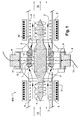
Le dispositif (400) de traitement d'un fluide, représenté sur la figure 1, est destiné à réduire la quantité d'agents pathogènes au sein d'un fluide. Ce dispositif comprend, dans le sens d'écoulement dudit fluide, selon un axe principal longitudinal :
- un conduit d'entrée (2) du fluide équipé d'un moyen (3) générant un champ électromagnétique (6) au sein dudit conduit d'entrée (2),
- une enceinte (1) définissant une cavité de traitement dudit fluide et comprenant au moins un moyen (8) de génération d'ondes ultrasonores en direction du centre de ladite cavité,
- un conduit de sortie (2') du fluide, équipé d'un moyen (3') générant un champ électromagnétique (6') au sein dudit conduit de sortie (2'), et
- un réflecteur d'ondes ultrasonores (4), magnétisable, disposé selon l'axe principal longitudinal dudit dispositif (400), et comprenant une partie centrale (5) située dans la cavité de l'enceinte (1) et un prolongement situé dans chacun des conduits d'entrée (2) et de sortie (2') du fluide.
- an inlet duct (2) for the fluid equipped with means (3) generating an electromagnetic field (6) within said inlet duct (2),
- an enclosure (1) defining a treatment cavity of said fluid and comprising at least one means (8) for generating ultrasonic waves towards the center of said cavity,
- an outlet duct (2 ') of the fluid, equipped with means (3') generating an electromagnetic field (6 ') within said outlet duct (2'), and
- a magnetizable ultrasonic wave reflector (4) arranged along the longitudinal principal axis of said device (400), and comprising a central portion (5) located in the cavity of the enclosure (1) and an extension located in each inlet (2) and outlet (2 ') conduits of the fluid.
L'enceinte de traitement (1) peut avoir une forme quelconque, mais est de préférence cylindrique comme cela ressortira plus clairement sur la figure 3. Le réflecteur d'ondes ultrasonores (4) comportant de la ferrite magnétique, possède une partie centrale (5), qui devient magnétique sous l'influence des bobines (3) et (3').The treatment chamber (1) may have any shape, but is preferably cylindrical as will become more clearly apparent in FIG. 3. The ultrasonic wave reflector (4) comprising magnetic ferrite has a central portion (5). ), which becomes magnetic under the influence of the coils (3) and (3 ').
Comme on l'observe sur la figure 1, les conduits d'entrée (2) et de sortie (2') du fluide comprennent des supports (20) qui maintiennent le réflecteur d'ondes ultrasonores (4) selon l'axe principal longitudinal du dispositif (400).As seen in FIG. 1, the fluid inlet (2) and outlet (2 ') ducts comprise supports (20) which hold the ultrasonic wave reflector (4) along the longitudinal main axis of the device (400).
chacun des moyens engendrant un champ électromagnétique, de préférence des bobines électromagnétiques, possède une composante de champ magnétique de 1 à 5 Tesla, de préférence, 1 à 2 Tesla.each of the means generating an electromagnetic field, preferably coils electromagnetic field, has a magnetic field component of 1 to 5 Tesla, preferably 1 to 2 Tesla.
Ces valeurs permettent tout d'abord d'éviter les dépôts d'un biofilm bactérien sur les parois des conduits d'entrée (2) et de sortie (2') en contact avec le fluide à traiter. Ces valeurs de champ magnétique, permettent également de magnétiser le réflecteur d'ondes ultrasonores (4) de manière directe, et de magnétiser de manière indirecte le centre (5) du réflecteur d'ondes ultrasonores (4). Cette magnétisation du centre (5) du réflecteur (4) permet d'obtenir une induction magnétique forte au niveau de la zone (7) de circulation du fluide dans l'enceinte de traitement (1).These values make it possible first of all to avoid deposits of a bacterial biofilm on the walls of the inlet (2) and outlet (2 ') ducts in contact with the fluid to be treated. These magnetic field values also make it possible to magnetize the ultrasonic wave reflector (4) in a direct manner, and to indirectly magnetize the center (5) of the ultrasonic wave reflector (4). This magnetization of the center (5) of the reflector (4) makes it possible to obtain a strong magnetic induction at the level of the zone (7) for circulation of the fluid in the treatment chamber (1).
Enfin, de telles valeurs de champ magnétique, permettent de créer une zone propice à la réduction de la quantité d'agents pathogènes au sein dudit fluide et en particulier dans la zone (7) de circulation du fluide.Finally, such magnetic field values, allow to create an area conducive to reducing the amount of pathogens within said fluid and in particular in the area (7) of fluid circulation.
La présence du réflecteur d'ondes ultrasonores (4) permet d'induire une aimantation permanente. Ainsi, les ondes ultrasonores produites dans l'enceinte de traitement sont accélérées ce qui favorise la destruction des agents pathogènes.The presence of the ultrasonic wave reflector (4) makes it possible to induce permanent magnetization. Thus, the ultrasonic waves produced in the treatment chamber are accelerated which promotes the destruction of pathogens.
Les bobines (3 et 3') qui génèrent un champ magnétique, comprennent des moyens d'alimentation électrique (31).The coils (3 and 3 ') which generate a magnetic field, comprise power supply means (31).
Le dispositif (400), tel que représenté sur la figure 1 comprend au moins deux transducteurs ultrasonores (9) portés par l'enceinte de traitement (1) dans des positions diamétralement opposées.The device (400) as shown in Figure 1 comprises at least two ultrasonic transducers (9) carried by the treatment chamber (1) in diametrically opposed positions.
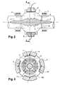
Le ou les moyens de génération d'ondes ultrasonores (8), qui comprennent un transducteur ultrasonore (9), génèrent des ondes ultrasonores qui traversent le flux de fluide au sein de l'enceinte de traitement (1), en direction du réflecteur d'ondes ultrasonores (4), puis ces ondes ultrasonores sont réfléchies par ce dernier. Les ondes ultrasonores traversent ensuite une seconde fois le flux de fluide au sein de l'enceinte de traitement (1) et reviennent vers un récepteur situé à proximité du transducteur (9).The ultrasonic wave generating means (8), which comprises an ultrasonic transducer (9), generate ultrasonic waves which pass through the fluid flow within the treatment chamber (1), towards the ultrasonic wave reflector (4), and these ultrasonic waves are reflected by the latter. The ultrasonic waves then pass through the fluid flow a second time within the treatment chamber (1) and return to a receiver located near the transducer (9).
En d'autres termes, les ondes émises en faisceaux (11) traversent la zone de circulation du fluide (7) pour se réfléchir selon l'orientation (12) après réflexion sur le réflecteur d'ondes ultrasonores (4) ; la zone intermédiaire (13) présentant une influence magnétique et des vibrations fortes induites par les ondes ultrasonores. Par conséquent, c'est dans la zone intermédiaire (13) que les agents pathogènes seront détruits.In other words, the waves emitted in bundles (11) pass through the fluid circulation zone (7) to be reflected according to the orientation (12) after reflection on the ultrasonic wave reflector (4); the intermediate zone (13) having a magnetic influence and strong vibrations induced by the ultrasonic waves. Therefore, it is in the intermediate zone (13) that the pathogens will be destroyed.
Comme on l'observe sur les figures 2 et 3, la disposition des transducteurs (8) concentriques permet d'avoir un point de convergence des ondes ultrasonores sur l'axe principal longitudinal du dispositif (400), et plus particulièrement sur le réflecteur d'ondes ultrasonores (4). Le cheminement des ondes ultrasonores émises est représenté par les indices (11) (ondes incidentes), et (12) (ondes réfléchies). Les zones d'influence magnétique centrale (131) et périphérique (132) dans lesquelles les ondes ultrasonores et magnétiques atteignent des vitesses élevées, entraînent la destruction des agents pathogènes et élimine tout risque de formation d'un biofilm.As can be seen in FIGS. 2 and 3, the arrangement of the concentric transducers (8) makes it possible to have a point of convergence of the ultrasonic waves on the longitudinal principal axis of the device (400), and more particularly on the reflector d ultrasonic waves (4). The path of the emitted ultrasonic waves is represented by the indices (11) (incident waves), and (12) (reflected waves). The magnetic central (131) and peripheral magnetic (132) zones in which the ultrasonic and magnetic waves reach high velocities result in the destruction of pathogens and eliminate any risk of biofilm formation.
Sans vouloir être lié à une quelconque théorie, l'inventeur pense que la zone (13) dans laquelle on observe un multiplexage des ondes magnétiques et des ondes ultrasonores, représente la zone essentielle de traitement.Without wishing to be bound to any theory, the inventor thinks that the zone (13) in which one observes a multiplexing of magnetic waves and ultrasonic waves, represents the essential area of treatment.
Comme on l'observe sur la figure 4, il peut exister une rétroréflexion des ondes ultrasonores émises (11) et réfléchies (12), sur le cylindre extérieur. Néanmoins, cette rétroréflection d'ondes (206) est atténuée.As seen in Figure 4, there may be retroreflection of the emitted (11) and reflected (12) ultrasonic waves on the outer cylinder. Nevertheless, this wave retroreflection (206) is attenuated.
Comme cela est illustré sur la figure 5, l'onde longitudinale (11) se réfléchit sur le réflecteur d'ondes ultrasonores (4) avec un angle (200) par rapport à la verticale, sa réflexion se situant en un angle moindre (201) par rapport à une visualisation plane (203). Une onde transversale existe également (202) favorisant le cisaillement en oblique par rapport à l'axe de circulation du fluide.As illustrated in FIG. 5, the longitudinal wave (11) is reflected on the ultrasonic wave reflector (4) at an angle (200) to the vertical, its reflection being at a lower angle (201). ) with respect to a planar display (203). A transverse wave also exists (202) favoring shearing obliquely with respect to the axis of circulation of the fluid.
Sur la figure 6, on observe que l'émission de l'onde (11) représente une amplitude (304) pour une longueur d'onde caractéristique du réglage adopté en fréquence. Le réglage de la puissance et de la fréquence d'émission des ondes ultrasonores s'effectuera en quantifiant les temps d'émission (302) de l'onde réfléchie (303). Le rapprochement de la cadence de l'émission suivante (301) permet de moduler et de multiplexer ces ondes ultrasonores pour une meilleure efficacité du dispositif.In FIG. 6, it is observed that the emission of the wave (11) represents an amplitude (304) for a characteristic wavelength of the frequency adopted setting. The adjustment of the power and the frequency of emission of the ultrasonic waves will be done by quantifying the emission times (302) of the reflected wave (303). The approximation of the rate of the next emission (301) makes it possible to modulate and multiplex these ultrasonic waves for a better efficiency of the device.
La figure 7 représente la visualisation spatiale de l'enchevêtrement des ondes incidentes (11) et réfléchies (12) et montre l'effet de cisaillement induit par le multiplexage des ondes. Les réglages peuvent être optimisés pour l'émission de l'onde initiale entre 0,1 m/s et 5 m/s en fonction du débit et de la vitesse de circulation du fluide à décontaminer de façon à ce que, pendant le temps de transit dans le dispositif (400), le nombre de trains d'ondes émis se situe entre 10 et 30 ou plus, de sorte à entraîner les vibrations et les ondes de cisaillement nécessaires pour détruire les agents pathogènes contenus dans le fluide à traiter.FIG. 7 represents the spatial visualization of the entanglement of the incident (11) and reflected (12) waves and shows the shearing effect induced by the multiplexing of the waves. The settings can be optimized for the emission of the initial wave between 0.1 m / s and 5 m / s depending on the flow rate and the flow rate of the fluid to be decontaminated so that during the time of in the device (400), the number of transmitted wave trains is between 10 and 30 or more, so as to cause the vibrations and shear waves necessary to destroy the pathogens contained in the fluid to be treated.
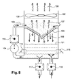
Dans un mode de réalisation préféré, le dispositif (400) décrit ci-dessus équipe une tour de réfrigération. Les tours de réfrigération étant connues de l'homme du métier celles-ci ne seront pas décrites en détail ci-après. Brièvement, les tours de réfrigération sont généralement rectangulaires et comportent une enveloppe (100) qui possède à sa partie inférieure un réservoir d'eau (101) qui circule par une pompe (104) pour être injectée en partie haute (105) puis va ruisseler sur des plaques obliques (103) pour effectuer un refroidissement de l'air par mélange. Un flux d'air (107) initié par un ventilateur (102) rejette l'air vers l'atmosphère en (108). Si une contamination bactérienne intervient dans la tour de réfrigération, la contamination bactérienne se retrouvera dispersée par l'humidité relative rejetée à l'extérieur par le flux (108) provoquant ainsi des contaminations autour de la tour de réfrigération. L'utilisation du dispositif (400) sur le recyclage d'injection d'eau en (115) permet de réduire ce risque.In a preferred embodiment, the device (400) described above equips a cooling tower. The cooling towers being known to those skilled in the art these will not be described in detail below. Briefly, the cooling towers are generally rectangular and comprise an envelope (100) which has at its lower part a water tank (101) which circulates by a pump (104) to be injected at the top (105) and then run off on oblique plates (103) for cooling the air by mixing. An airflow (107) initiated by a fan (102) releases air to the atmosphere at (108). If bacterial contamination occurs in the refrigeration tower, the bacterial contamination will be dispersed by the relative humidity released to the outside by the flow (108) thus causing contamination around the cooling tower. The use of the device (400) on the water injection recycling in (115) makes it possible to reduce this risk.
Claims (9)
Applications Claiming Priority (1)
| Application Number | Priority Date | Filing Date | Title |
|---|---|---|---|
| FR0551385A FR2886157B1 (en) | 2005-05-26 | 2005-05-26 | BACTERIAL PURIFIER |
Publications (2)
| Publication Number | Publication Date |
|---|---|
| EP1738775A1 true EP1738775A1 (en) | 2007-01-03 |
| EP1738775B1 EP1738775B1 (en) | 2009-04-29 |
Family
ID=34955280
Family Applications (1)
| Application Number | Title | Priority Date | Filing Date |
|---|---|---|---|
| EP06300518A Not-in-force EP1738775B1 (en) | 2005-05-26 | 2006-05-24 | Device for reducing the number of bacterial germs in a fluid |
Country Status (4)
| Country | Link |
|---|---|
| EP (1) | EP1738775B1 (en) |
| AT (1) | ATE429934T1 (en) |
| DE (1) | DE602006006503D1 (en) |
| FR (1) | FR2886157B1 (en) |
Cited By (3)
| Publication number | Priority date | Publication date | Assignee | Title |
|---|---|---|---|---|
| WO2010066999A1 (en) | 2008-12-09 | 2010-06-17 | Rc - Lux | Method and device for treating at least one compound carried in a liquid |
| CN103232127A (en) * | 2013-05-15 | 2013-08-07 | 陕西师范大学 | Sewage treater integrating ultrasonic cavitation and hydrodynamic cavitation |
| WO2022090658A1 (en) * | 2020-10-29 | 2022-05-05 | Marc Durand | Device for purifying a fluid comprising suspended particles |
Citations (6)
| Publication number | Priority date | Publication date | Assignee | Title |
|---|---|---|---|---|
| WO1997011908A2 (en) * | 1995-09-25 | 1997-04-03 | The National Engineering Research Center For Urban Pollution Control | Process and device for treating water contaminated with micro-organisms and/or harmful pollutants |
| WO1998005595A1 (en) * | 1996-08-01 | 1998-02-12 | Burnham Technologies Ltd. | Methods and apparatus for the application of combined fields to disinfect fluids |
| US5965093A (en) * | 1994-07-08 | 1999-10-12 | Amphion International, Limited | Decontamination system with improved components |
| WO2002034075A1 (en) * | 2000-10-27 | 2002-05-02 | Apit Corp. Sa | Method and device for sterilising a liquid |
| DE10056581A1 (en) * | 2000-07-17 | 2003-04-30 | Werner Buehre | Apparatus for killing bacteria, fungi, algae etc. in liquid media comprises plastic vessel which is provided with stainless steel electrodes, inductive coil and ultrasound generator |
| FR2841475A1 (en) * | 2002-06-28 | 2004-01-02 | Deschamps Lathus Sa | METHOD OF HEAT TREATMENT BY INDUCTION OF A SANITARY WATER PIPELINE AND SYSTEM FOR IMPLEMENTING SAME |
-
2005
- 2005-05-26 FR FR0551385A patent/FR2886157B1/en not_active Expired - Fee Related
-
2006
- 2006-05-24 AT AT06300518T patent/ATE429934T1/en not_active IP Right Cessation
- 2006-05-24 EP EP06300518A patent/EP1738775B1/en not_active Not-in-force
- 2006-05-24 DE DE602006006503T patent/DE602006006503D1/en active Active
Patent Citations (6)
| Publication number | Priority date | Publication date | Assignee | Title |
|---|---|---|---|---|
| US5965093A (en) * | 1994-07-08 | 1999-10-12 | Amphion International, Limited | Decontamination system with improved components |
| WO1997011908A2 (en) * | 1995-09-25 | 1997-04-03 | The National Engineering Research Center For Urban Pollution Control | Process and device for treating water contaminated with micro-organisms and/or harmful pollutants |
| WO1998005595A1 (en) * | 1996-08-01 | 1998-02-12 | Burnham Technologies Ltd. | Methods and apparatus for the application of combined fields to disinfect fluids |
| DE10056581A1 (en) * | 2000-07-17 | 2003-04-30 | Werner Buehre | Apparatus for killing bacteria, fungi, algae etc. in liquid media comprises plastic vessel which is provided with stainless steel electrodes, inductive coil and ultrasound generator |
| WO2002034075A1 (en) * | 2000-10-27 | 2002-05-02 | Apit Corp. Sa | Method and device for sterilising a liquid |
| FR2841475A1 (en) * | 2002-06-28 | 2004-01-02 | Deschamps Lathus Sa | METHOD OF HEAT TREATMENT BY INDUCTION OF A SANITARY WATER PIPELINE AND SYSTEM FOR IMPLEMENTING SAME |
Cited By (6)
| Publication number | Priority date | Publication date | Assignee | Title |
|---|---|---|---|---|
| WO2010066999A1 (en) | 2008-12-09 | 2010-06-17 | Rc - Lux | Method and device for treating at least one compound carried in a liquid |
| US9579614B2 (en) | 2008-12-09 | 2017-02-28 | Rc Lux | Device comprising a cavitation chamber with opposed radial and parallel faces, in communication with a secondary chamber, for treating compounds in a liquid |
| CN103232127A (en) * | 2013-05-15 | 2013-08-07 | 陕西师范大学 | Sewage treater integrating ultrasonic cavitation and hydrodynamic cavitation |
| CN103232127B (en) * | 2013-05-15 | 2014-03-05 | 陕西师范大学 | Sewage treater integrating ultrasonic cavitation and hydrodynamic cavitation |
| WO2022090658A1 (en) * | 2020-10-29 | 2022-05-05 | Marc Durand | Device for purifying a fluid comprising suspended particles |
| FR3115708A1 (en) * | 2020-10-29 | 2022-05-06 | Marc Durand | Device for purifying a fluid comprising particles in suspension |
Also Published As
| Publication number | Publication date |
|---|---|
| EP1738775B1 (en) | 2009-04-29 |
| FR2886157A1 (en) | 2006-12-01 |
| ATE429934T1 (en) | 2009-05-15 |
| FR2886157B1 (en) | 2007-12-07 |
| DE602006006503D1 (en) | 2009-06-10 |
Similar Documents
| Publication | Publication Date | Title |
|---|---|---|
| EP0183583B1 (en) | Ultrasonic device | |
| US6649069B2 (en) | Active acoustic piping | |
| US9011698B2 (en) | Method and devices for sonicating liquids with low-frequency high energy ultrasound | |
| US7373805B2 (en) | Apparatus for directing particles in a fluid | |
| CA2194543C (en) | Decontamination system with improved components | |
| EP1738775B1 (en) | Device for reducing the number of bacterial germs in a fluid | |
| ES2771350T3 (en) | Ultrasonic cleaning of vessels and tubes | |
| EP0648531B1 (en) | Fluid processing | |
| US6749406B2 (en) | Ultrasonic pump with non-planar transducer for generating focused longitudinal waves and pumping methods | |
| WO1999061149A1 (en) | Reactor with acoustic cavitation | |
| JP5219096B2 (en) | Method and apparatus for processing liquids | |
| EP1148943B1 (en) | Process and apparatus for irradiating fluids | |
| FR2671737A1 (en) | MODULAR TUBULAR ULTRA-SONIC REACTOR UNIT. | |
| CN100344385C (en) | Megasonic probe energy director | |
| US20030173307A1 (en) | Assembly and method for purifying water at a point of use and apparatus and method for testing same | |
| Radel et al. | Breakdown of immobilisation/separation and morphology changes of yeast suspended in water-rich ethanol mixtures exposed to ultrasonic plane standing waves | |
| FR2743929A1 (en) | DEVICE FOR GENERATING ULTRASONIC WAVES | |
| US7608440B2 (en) | Apparatus for ultrasonic microbial disruption | |
| FR2549746A1 (en) | Method, device and machine for cleaning hollow objects by ultrasound | |
| FR2821557A1 (en) | PLASMA STERILIZATION SYSTEM FOR OBJECTS HAVING OUTPUT CHANNELS | |
| FR2730278A1 (en) | METHOD FOR CONDITIONING A FLOW OF A FLUID AND CONDITIONER FOR FLOWING A FLUID | |
| BE1009104A3 (en) | Venturi a cavitation and multiple nozzles. | |
| WO1999053186A1 (en) | Device for preparing fuel | |
| Gallego Juárez | Macrosonics: Phenomena, transducers and applications | |
| WO2006130237A1 (en) | Hourglass-shaped cavitation chamber |
Legal Events
| Date | Code | Title | Description |
|---|---|---|---|
| PUAI | Public reference made under article 153(3) epc to a published international application that has entered the european phase |
Free format text: ORIGINAL CODE: 0009012 |
|
| AK | Designated contracting states |
Kind code of ref document: A1 Designated state(s): AT BE BG CH CY CZ DE DK EE ES FI FR GB GR HU IE IS IT LI LT LU LV MC NL PL PT RO SE SI SK TR |
|
| AX | Request for extension of the european patent |
Extension state: AL BA HR MK YU |
|
| 17P | Request for examination filed |
Effective date: 20070703 |
|
| AKX | Designation fees paid |
Designated state(s): AT BE BG CH CY CZ DE DK EE ES FI FR GB GR HU IE IS IT LI LT LU LV MC NL PL PT RO SE SI SK TR |
|
| GRAP | Despatch of communication of intention to grant a patent |
Free format text: ORIGINAL CODE: EPIDOSNIGR1 |
|
| GRAS | Grant fee paid |
Free format text: ORIGINAL CODE: EPIDOSNIGR3 |
|
| GRAA | (expected) grant |
Free format text: ORIGINAL CODE: 0009210 |
|
| AK | Designated contracting states |
Kind code of ref document: B1 Designated state(s): AT BE BG CH CY CZ DE DK EE ES FI FR GB GR HU IE IS IT LI LT LU LV MC NL PL PT RO SE SI SK TR |
|
| REG | Reference to a national code |
Ref country code: GB Ref legal event code: FG4D Free format text: NOT ENGLISH |
|
| REG | Reference to a national code |
Ref country code: CH Ref legal event code: EP |
|
| REF | Corresponds to: |
Ref document number: 602006006503 Country of ref document: DE Date of ref document: 20090610 Kind code of ref document: P |
|
| REG | Reference to a national code |
Ref country code: IE Ref legal event code: FG4D |
|
| REG | Reference to a national code |
Ref country code: CH Ref legal event code: NV Representative=s name: KIRKER & CIE S.A. |
|
| NLV1 | Nl: lapsed or annulled due to failure to fulfill the requirements of art. 29p and 29m of the patents act | ||
| PG25 | Lapsed in a contracting state [announced via postgrant information from national office to epo] |
Ref country code: FI Free format text: LAPSE BECAUSE OF FAILURE TO SUBMIT A TRANSLATION OF THE DESCRIPTION OR TO PAY THE FEE WITHIN THE PRESCRIBED TIME-LIMIT Effective date: 20090429 Ref country code: LT Free format text: LAPSE BECAUSE OF FAILURE TO SUBMIT A TRANSLATION OF THE DESCRIPTION OR TO PAY THE FEE WITHIN THE PRESCRIBED TIME-LIMIT Effective date: 20090429 Ref country code: AT Free format text: LAPSE BECAUSE OF FAILURE TO SUBMIT A TRANSLATION OF THE DESCRIPTION OR TO PAY THE FEE WITHIN THE PRESCRIBED TIME-LIMIT Effective date: 20090429 Ref country code: ES Free format text: LAPSE BECAUSE OF FAILURE TO SUBMIT A TRANSLATION OF THE DESCRIPTION OR TO PAY THE FEE WITHIN THE PRESCRIBED TIME-LIMIT Effective date: 20090809 Ref country code: PT Free format text: LAPSE BECAUSE OF FAILURE TO SUBMIT A TRANSLATION OF THE DESCRIPTION OR TO PAY THE FEE WITHIN THE PRESCRIBED TIME-LIMIT Effective date: 20090829 |
|
| PG25 | Lapsed in a contracting state [announced via postgrant information from national office to epo] |
Ref country code: LV Free format text: LAPSE BECAUSE OF FAILURE TO SUBMIT A TRANSLATION OF THE DESCRIPTION OR TO PAY THE FEE WITHIN THE PRESCRIBED TIME-LIMIT Effective date: 20090429 Ref country code: NL Free format text: LAPSE BECAUSE OF FAILURE TO SUBMIT A TRANSLATION OF THE DESCRIPTION OR TO PAY THE FEE WITHIN THE PRESCRIBED TIME-LIMIT Effective date: 20090429 Ref country code: IS Free format text: LAPSE BECAUSE OF FAILURE TO SUBMIT A TRANSLATION OF THE DESCRIPTION OR TO PAY THE FEE WITHIN THE PRESCRIBED TIME-LIMIT Effective date: 20090829 Ref country code: SE Free format text: LAPSE BECAUSE OF FAILURE TO SUBMIT A TRANSLATION OF THE DESCRIPTION OR TO PAY THE FEE WITHIN THE PRESCRIBED TIME-LIMIT Effective date: 20090729 Ref country code: PL Free format text: LAPSE BECAUSE OF FAILURE TO SUBMIT A TRANSLATION OF THE DESCRIPTION OR TO PAY THE FEE WITHIN THE PRESCRIBED TIME-LIMIT Effective date: 20090429 Ref country code: SI Free format text: LAPSE BECAUSE OF FAILURE TO SUBMIT A TRANSLATION OF THE DESCRIPTION OR TO PAY THE FEE WITHIN THE PRESCRIBED TIME-LIMIT Effective date: 20090429 |
|
| REG | Reference to a national code |
Ref country code: IE Ref legal event code: FD4D |
|
| PG25 | Lapsed in a contracting state [announced via postgrant information from national office to epo] |
Ref country code: MC Free format text: LAPSE BECAUSE OF NON-PAYMENT OF DUE FEES Effective date: 20090531 |
|
| PG25 | Lapsed in a contracting state [announced via postgrant information from national office to epo] |
Ref country code: IE Free format text: LAPSE BECAUSE OF FAILURE TO SUBMIT A TRANSLATION OF THE DESCRIPTION OR TO PAY THE FEE WITHIN THE PRESCRIBED TIME-LIMIT Effective date: 20090429 Ref country code: DK Free format text: LAPSE BECAUSE OF FAILURE TO SUBMIT A TRANSLATION OF THE DESCRIPTION OR TO PAY THE FEE WITHIN THE PRESCRIBED TIME-LIMIT Effective date: 20090429 Ref country code: RO Free format text: LAPSE BECAUSE OF FAILURE TO SUBMIT A TRANSLATION OF THE DESCRIPTION OR TO PAY THE FEE WITHIN THE PRESCRIBED TIME-LIMIT Effective date: 20090429 Ref country code: EE Free format text: LAPSE BECAUSE OF FAILURE TO SUBMIT A TRANSLATION OF THE DESCRIPTION OR TO PAY THE FEE WITHIN THE PRESCRIBED TIME-LIMIT Effective date: 20090429 Ref country code: CZ Free format text: LAPSE BECAUSE OF FAILURE TO SUBMIT A TRANSLATION OF THE DESCRIPTION OR TO PAY THE FEE WITHIN THE PRESCRIBED TIME-LIMIT Effective date: 20090429 |
|
| PG25 | Lapsed in a contracting state [announced via postgrant information from national office to epo] |
Ref country code: SK Free format text: LAPSE BECAUSE OF FAILURE TO SUBMIT A TRANSLATION OF THE DESCRIPTION OR TO PAY THE FEE WITHIN THE PRESCRIBED TIME-LIMIT Effective date: 20090429 |
|
| PLBE | No opposition filed within time limit |
Free format text: ORIGINAL CODE: 0009261 |
|
| STAA | Information on the status of an ep patent application or granted ep patent |
Free format text: STATUS: NO OPPOSITION FILED WITHIN TIME LIMIT |
|
| PG25 | Lapsed in a contracting state [announced via postgrant information from national office to epo] |
Ref country code: BG Free format text: LAPSE BECAUSE OF FAILURE TO SUBMIT A TRANSLATION OF THE DESCRIPTION OR TO PAY THE FEE WITHIN THE PRESCRIBED TIME-LIMIT Effective date: 20090729 |
|
| 26N | No opposition filed |
Effective date: 20100201 |
|
| PGFP | Annual fee paid to national office [announced via postgrant information from national office to epo] |
Ref country code: LU Payment date: 20100324 Year of fee payment: 5 |
|
| PGFP | Annual fee paid to national office [announced via postgrant information from national office to epo] |
Ref country code: GB Payment date: 20100330 Year of fee payment: 5 |
|
| PGFP | Annual fee paid to national office [announced via postgrant information from national office to epo] |
Ref country code: BE Payment date: 20100322 Year of fee payment: 5 Ref country code: DE Payment date: 20100329 Year of fee payment: 5 |
|
| PG25 | Lapsed in a contracting state [announced via postgrant information from national office to epo] |
Ref country code: GR Free format text: LAPSE BECAUSE OF FAILURE TO SUBMIT A TRANSLATION OF THE DESCRIPTION OR TO PAY THE FEE WITHIN THE PRESCRIBED TIME-LIMIT Effective date: 20090730 |
|
| PGFP | Annual fee paid to national office [announced via postgrant information from national office to epo] |
Ref country code: CH Payment date: 20100420 Year of fee payment: 5 |
|
| PG25 | Lapsed in a contracting state [announced via postgrant information from national office to epo] |
Ref country code: IT Free format text: LAPSE BECAUSE OF FAILURE TO SUBMIT A TRANSLATION OF THE DESCRIPTION OR TO PAY THE FEE WITHIN THE PRESCRIBED TIME-LIMIT Effective date: 20090429 |
|
| PG25 | Lapsed in a contracting state [announced via postgrant information from national office to epo] |
Ref country code: HU Free format text: LAPSE BECAUSE OF FAILURE TO SUBMIT A TRANSLATION OF THE DESCRIPTION OR TO PAY THE FEE WITHIN THE PRESCRIBED TIME-LIMIT Effective date: 20091030 |
|
| PG25 | Lapsed in a contracting state [announced via postgrant information from national office to epo] |
Ref country code: TR Free format text: LAPSE BECAUSE OF FAILURE TO SUBMIT A TRANSLATION OF THE DESCRIPTION OR TO PAY THE FEE WITHIN THE PRESCRIBED TIME-LIMIT Effective date: 20090429 |
|
| PG25 | Lapsed in a contracting state [announced via postgrant information from national office to epo] |
Ref country code: CY Free format text: LAPSE BECAUSE OF FAILURE TO SUBMIT A TRANSLATION OF THE DESCRIPTION OR TO PAY THE FEE WITHIN THE PRESCRIBED TIME-LIMIT Effective date: 20090429 |
|
| BERE | Be: lapsed |
Owner name: DREAN, HENRI Effective date: 20110531 |
|
| REG | Reference to a national code |
Ref country code: CH Ref legal event code: PL |
|
| GBPC | Gb: european patent ceased through non-payment of renewal fee |
Effective date: 20110524 |
|
| PG25 | Lapsed in a contracting state [announced via postgrant information from national office to epo] |
Ref country code: CH Free format text: LAPSE BECAUSE OF NON-PAYMENT OF DUE FEES Effective date: 20110531 Ref country code: LI Free format text: LAPSE BECAUSE OF NON-PAYMENT OF DUE FEES Effective date: 20110531 |
|
| REG | Reference to a national code |
Ref country code: DE Ref legal event code: R119 Ref document number: 602006006503 Country of ref document: DE Effective date: 20111201 |
|
| PG25 | Lapsed in a contracting state [announced via postgrant information from national office to epo] |
Ref country code: BE Free format text: LAPSE BECAUSE OF NON-PAYMENT OF DUE FEES Effective date: 20110531 |
|
| PG25 | Lapsed in a contracting state [announced via postgrant information from national office to epo] |
Ref country code: GB Free format text: LAPSE BECAUSE OF NON-PAYMENT OF DUE FEES Effective date: 20110524 |
|
| PG25 | Lapsed in a contracting state [announced via postgrant information from national office to epo] |
Ref country code: LU Free format text: LAPSE BECAUSE OF NON-PAYMENT OF DUE FEES Effective date: 20110524 |
|
| PG25 | Lapsed in a contracting state [announced via postgrant information from national office to epo] |
Ref country code: DE Free format text: LAPSE BECAUSE OF NON-PAYMENT OF DUE FEES Effective date: 20111201 |
|
| PGFP | Annual fee paid to national office [announced via postgrant information from national office to epo] |
Ref country code: FR Payment date: 20130424 Year of fee payment: 8 |
|
| REG | Reference to a national code |
Ref country code: FR Ref legal event code: ST Effective date: 20150130 |
|
| PG25 | Lapsed in a contracting state [announced via postgrant information from national office to epo] |
Ref country code: FR Free format text: LAPSE BECAUSE OF NON-PAYMENT OF DUE FEES Effective date: 20140602 |