EP1743687A1 - Air filter - Google Patents
Air filter Download PDFInfo
- Publication number
- EP1743687A1 EP1743687A1 EP06003522A EP06003522A EP1743687A1 EP 1743687 A1 EP1743687 A1 EP 1743687A1 EP 06003522 A EP06003522 A EP 06003522A EP 06003522 A EP06003522 A EP 06003522A EP 1743687 A1 EP1743687 A1 EP 1743687A1
- Authority
- EP
- European Patent Office
- Prior art keywords
- air
- base
- filter
- concentrating tube
- passageway
- Prior art date
- Legal status (The legal status is an assumption and is not a legal conclusion. Google has not performed a legal analysis and makes no representation as to the accuracy of the status listed.)
- Withdrawn
Links
Images


Classifications
-
- B—PERFORMING OPERATIONS; TRANSPORTING
- B01—PHYSICAL OR CHEMICAL PROCESSES OR APPARATUS IN GENERAL
- B01D—SEPARATION
- B01D46/00—Filters or filtering processes specially modified for separating dispersed particles from gases or vapours
- B01D46/0039—Filters or filtering processes specially modified for separating dispersed particles from gases or vapours with flow guiding by feed or discharge devices
- B01D46/0047—Filters or filtering processes specially modified for separating dispersed particles from gases or vapours with flow guiding by feed or discharge devices for discharging the filtered gas
- B01D46/0049—Filters or filtering processes specially modified for separating dispersed particles from gases or vapours with flow guiding by feed or discharge devices for discharging the filtered gas containing fixed gas displacement elements or cores
-
- B—PERFORMING OPERATIONS; TRANSPORTING
- B01—PHYSICAL OR CHEMICAL PROCESSES OR APPARATUS IN GENERAL
- B01D—SEPARATION
- B01D46/00—Filters or filtering processes specially modified for separating dispersed particles from gases or vapours
- B01D46/24—Particle separators, e.g. dust precipitators, using rigid hollow filter bodies
- B01D46/2403—Particle separators, e.g. dust precipitators, using rigid hollow filter bodies characterised by the physical shape or structure of the filtering element
-
- F—MECHANICAL ENGINEERING; LIGHTING; HEATING; WEAPONS; BLASTING
- F02—COMBUSTION ENGINES; HOT-GAS OR COMBUSTION-PRODUCT ENGINE PLANTS
- F02M—SUPPLYING COMBUSTION ENGINES IN GENERAL WITH COMBUSTIBLE MIXTURES OR CONSTITUENTS THEREOF
- F02M35/00—Combustion-air cleaners, air intakes, intake silencers, or induction systems specially adapted for, or arranged on, internal-combustion engines
- F02M35/02—Air cleaners
- F02M35/024—Air cleaners using filters, e.g. moistened
- F02M35/02475—Air cleaners using filters, e.g. moistened characterised by the shape of the filter element
- F02M35/02483—Cylindrical, conical, oval, spherical or the like filter elements; wounded filter elements
-
- B—PERFORMING OPERATIONS; TRANSPORTING
- B01—PHYSICAL OR CHEMICAL PROCESSES OR APPARATUS IN GENERAL
- B01D—SEPARATION
- B01D2279/00—Filters adapted for separating dispersed particles from gases or vapours specially modified for specific uses
- B01D2279/60—Filters adapted for separating dispersed particles from gases or vapours specially modified for specific uses for the intake of internal combustion engines or turbines
Abstract
An air filter (10) includes a filter core (12) and a base (13). Outer air is filtered by the filter core (12), and then flows to the base (13), which has a passageway provided in its center and connected with an air intake of an engine. An air concentrating tube (133) is provided on the upper end of the passageway, extending in the inside of the filer fore, having an upper end with a large opening, gradually shrinking down to have a lower end with a trumpet shape. The large upper end of the air concentrating tube can permit filtered clean air to flow smoothly through into the passageway (134) so that no turbulent current may happen in the air filter and filtered clean air may flow in an engine smoothly for boosting effectiveness of burning in the engine.
Description
- This invention relates to an automobile air filter, particularly to one provided with a base, which has an air concentrating tube with an upper end with a large opening and gradually shrinking down to have a lower end with a small opening so that filtered clean air may largely and quickly flow into an engine of an automobile, enhancing largely burning effect of the engine.
- When a conventional engine of an automobile needs mixed gas of air and gasoline for combustion, with an air intake of an engine connected with the air filter. However, external air is mixed with micro dust particles, potentially impairing an inner wall of the engine if these dust particles should enter the engine, cutting down the service life of an engine and a piston of its cylinder.
- A know conventional air filter for automobiles shown in Fig. 1 includes a
housing 1, anair filter core 2 and abase 3 as main components. Thehousing 1 is for collecting outer air to flow into thefilter core 2, which filters off micro dust particles mixed in air, which may be remained on the outer surface of the filter core, letting filtered clean air flow into a passageway 4 in the center of thebase 3, and then into the air intake of an engine of an automobile. - By the way, the diameter of the passageway 4 of the
base 3 is rather small, and located at the same level of the bottom of thebase 3 so filtered clean air may not be able to completely flow into the passageway 4, with partial clean air colliding the wall of thebase 3 and becoming turbulent current, which may hamper smooth flow of filtered clean air into the engine. Therefore, the mixed gas flowing in the engine may have incorrect proportion so the mixed air and gas may not be able to burn completely and exhausted out of the engine, wasting partial gasoline and polluting the environment with mono oxide mixed in exhausted out gas, - The invention has been devised to offer an air filter for an automobile to let filtered clean air to smoothly flow in the engine of an automobile.
- The feature of the invention is a housing, a filter core, and a base combined together to make up an air filter. When outer air is guided to flow into the filter core from the housing, the filter core filters off micro dust particles. The base is combined with the filter core in a sealed condition, having a passageway in its center to connect with an intake of an engine. Further an air concentrating tube is provided in the base, facing the lower end of the filter core, having an upper end with a large opening and gradually shrinking down to have a lower end with a trumpet-shape so the filtered clean air may smoothly flow through it in an accelerated condition to enter the engine, not producing turbulent current, and accelerating its speed to flow into the engine, in which mixed air and gas may burn completely, lowering pollution by exhausted waste gas mixed with mono oxide.
- This invention will be better understood by referring to the accompanying drawing wherein:
- Figure 1 is a cross-sectional view of a conventional air filter;
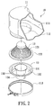
- Figure 2 is an exploded perspective view of a first embodiment of an air filter in the present invention;
- Figure 3 is a cross-sectional view of the first embodiment of an air filter in the present invention;
- Figure 4 is an exploded perspective view of a second embodiment of an air filter in the present invention;
- Figure 5 is a cross-sectional view of the second embodiment of an air filter in the present invention;
- Figure 6 is a cross-sectional view of a third embodiment of an air filter in the present invention;
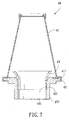
- Figure 7 is a cross-sectional view of a fourth embodiment of an air filter in the present invention; and,
- Figure 8 is a perspective view of another embodiment of an air concentrating tube in the present invention.
- A first embodiment of an
air filter 10 in the present invention, as shown in Fig. 2, includes ahousing 11, afilter core 12, and abase 13 as main components combined together. - The
housing 11 is hollow and provided with anair inlet 111 at one end and anair outlet 112 at the other end, and outer air flows through theair inlet 111 into the interior and then out of theair outlet 112 into thefilter core 12, which is combined with thehousing 11 at theair outlet 112 and with thebase 13 at the same time. - The
filter core 12 is shaped conical and made of afiber net 121 with a plurality of projecting waves for augmenting its area to contact air so that micro dust particles mixed in outer air may be filtered off and remain on its outer surface, prevented from entering the interior of thefilter core 12. Further, thefilter core 12 has ahollow disc 122 formed in its lower end, and thehollow disc 122 has its upper surface contacting with the periphery of theair outlet 12, and its lower surface contacting with the upper periphery of thebase 13, with aclamping ring 113 tightly clamping thefilter core 12 and thebase 13 with thehousing 11. - The
base 13 has abottom 131, and aflange 132 just corresponding to thedisc 122 of thefilter core 12 and contacting with theair outlet 112 of thehousing 11 in a sealed condition. Further, anair concentrating tube 133 is provided through the center portion of thebottom 131 of thebase 13, having an upper end with a large opening and gradually shrinking down to have a lower end with a trumpet shape of a small area, and the upper end located a little higher than theflange 132 of thebase 13 and just under the bottom of thefilter core 12 after thefilter core 12 is combined with thebase 13. Theair concentrating tube 133 has apassageway 134 extending down outward from its bottom and connected with the air intake (not shown) of the engine of an automobile. - Next, the function of the air filter in the invention will be described below. As shown in Fig. 3, when the
air filter 10 receives outer air, it may flow through thehousing 11 into thefilter core 12, which filters outer air and eliminates micro dust particles stopped on its outer surface of thefiber net 121 and then filtered clean air may flow into theair concentrating tube 133 of thebase 13, which has the large upper end opening. Then the clean air may flow through theair concentrating tube 133 to become an accelerated current because of pressure change, so clean air may enter thepassageway 134 smoothly and quickly enough for entering the engine, wherein mixed gas with air may burn completely, with the effectiveness of the engine boosted largely. - Next, Figs. 4 and 5 shows a second embodiment of an
air filter 20, which includes afilter core 21, abase 22 and anair concentrating tube 23. Their structure are almost the same as the first embodiment, so only the different structure are to be described below. - The
base 22 has atubular passageway 221 formed in a lower portion, and thetubular passageway 221 has its upper periphery screwed withbolts 222 also screwing withbolt holes 232 bored in a bottom of theair concentrating tube 23, so thebase 22 is tightly screwed together with theair concentrating tube 23. Further, aclamping ring 211 is fitted tightly around the flange of thefilter core 21 and the flange of thebase 22, combining together thefilter core 21, thebase 22 and theair concentrating tube 23. Therefore, if any components of theair filter 20 should be damaged, it would be easily, replaced with a new one, reducing repairing cost, needless to discard the whole air filter. In addition, the components can be made of different materials according to their function, beefing up the effect of the air filter as well. - Further, Fig.6 shows a third embodiment of an
air filter 30, which also includes ahousing 31, afilter core 32, abase 33 and anair concentrating tube 34 formed integral with thebase 33. Their structure is almost the same as the fitst embodiment, so the different structure only will be described below. - The
housing 31 is shaped as a hollow round tube, having anupper air inlet 311 with a small diameter and alower air outlet 312 with a large diameter. And thebase 33 is tightly connected with thehousing 31 by aclamping ring 313. When outer air flows through theair inlet 311 into thefilter core 32, it flows into the upper portion of thefilter core 32 and then into its interior in an even condition, with micro dust particles also evenly hampered and kept remained on the outer surface of the filter core to permit the filter core usable for a long time. - Further, Fig. 7 shows a fourth embodiment of an
air filter 40 in the invention, which includes afilter core 41, abase 42 and anair concentrating tube 43. The different structure from the first embodiment is that thefilter core 41 and thebase 42 are firmly combined together by aclamping ring 411, and thepassageway 421 of thebase 42 is provided withfemale threads 422 in its inner wall to engage withmale threads 431 formed in a lower portion of theair concentrating tube 43 so thepassageway 421 may be threadably combined with theair concentrating tube 43 removably, with no need of other fastening means for lower cost. - Next, another embodiment of an
air concentrating tube 53 is shown in Fig. 8, which has an upper end with an opening with four sides and gradually shrinking down to have a lower end with a round trumpet shape so theair concentrating tube 53 has a comparatively large dimension for air to enter. - The invention has the following advantages as can be understood from the foresaid description.
- The air filter has an air concentrating structure possible to let filtered clean air to flow through the air concentrating tube, which can boost the air to flow smoothly and in an accelerated speed to enter an engine of an automobile to permit mixed are and gas completely burn up to boost the effectiveness of the engine.
- While the preferred embodiment of the invention have been described above, it will be recognized and understood that various modifications may be made therein and the appended claims are intended to cover all the modifications that may fall within the spirit and scope of the invention.
Claims (9)
- An air filter comprising:A filter core functioning to filter off micro dust particles mixed in air so that filtered cleans air may flow into a base, said filter core combined with said base in a sealed condition; and,Said base provided with a passageway connected with an air concentrating tube extending upward, said air concentrating tube having an upper end with a large opening and gradually shrinking down to have a lower end with a trumpet shape of a small opening, said air concentrating tube having its upper end located a little higher than said base and a larger dimension than that of said passageway.
- The air filter as claimed in Claim 1, wherein a housing is provided to cover up said filter core and said base, shaped hollow and having an air inlet and an air outlet, said air inlet guiding outer air into an interior of said housing to said air outlet, and said outlet is connected with said filter core and said base.
- The air filter as claimed in Claim 1, wherein said base is provided with an upper flange, said filer core is provided with a hollow disc to correspond to said flange, said hollow disc is closely connected with said flange, with said air concentrating tube located a little higher than said flange and just at the lower end of said filer core.
- The air filter as claimed in Claim 1, wherein said base and said air concentrating tube are formed integral.
- The air filter as claimed in Claim 1, wherein a passageway member is removably connected with the bottom of said base, said air concentrating tube is provided with plural threaded holes in its bottom end, permitting said base tightly connected with said air concentrating tube with bolts.
- The air filter as claimed in Claim 1, wherein said passageway of said base is provided with female threads in its inner wall, and said air concentrating tube is provided with male threads to engage with said female threads so that said passageway may be threadably connected with said air concentrating tube.
- The air filter as claimed in Claim 1, wherein said air concentrating tube has an upper end with a round opening, shrinking down gradually to have a lower end with a trumpet shape.
- The air filter as claimed in Claim 1, wherein said air concentrating tube is provided with an upper end with four sides, shrinking down gradually to have a lower end with a trumpet shape.
- The air filter as claimed in Claim 1, wherein after said filter core is closely connected with said base, and a clamping ring is fixed around the connected part of said filter core and said base.
Priority Applications (1)
| Application Number | Priority Date | Filing Date | Title |
|---|---|---|---|
| EP06003522A EP1743687A1 (en) | 2006-02-21 | 2006-02-21 | Air filter |
Applications Claiming Priority (1)
| Application Number | Priority Date | Filing Date | Title |
|---|---|---|---|
| EP06003522A EP1743687A1 (en) | 2006-02-21 | 2006-02-21 | Air filter |
Publications (2)
| Publication Number | Publication Date |
|---|---|
| EP1743687A1 true EP1743687A1 (en) | 2007-01-17 |
| EP1743687A8 EP1743687A8 (en) | 2007-10-24 |
Family
ID=38529758
Family Applications (1)
| Application Number | Title | Priority Date | Filing Date |
|---|---|---|---|
| EP06003522A Withdrawn EP1743687A1 (en) | 2006-02-21 | 2006-02-21 | Air filter |
Country Status (1)
| Country | Link |
|---|---|
| EP (1) | EP1743687A1 (en) |
Cited By (1)
| Publication number | Priority date | Publication date | Assignee | Title |
|---|---|---|---|---|
| WO2012172020A3 (en) * | 2011-06-17 | 2013-02-28 | Mahle International Gmbh | Filter element and filter device |
Citations (4)
| Publication number | Priority date | Publication date | Assignee | Title |
|---|---|---|---|---|
| FR1563990A (en) * | 1968-03-05 | 1969-04-18 | ||
| US5195527A (en) * | 1989-05-19 | 1993-03-23 | Intersurgical Limited | Respiratory filters |
| EP0673666A1 (en) * | 1994-03-23 | 1995-09-27 | Efficience Sa | Cartridge for a filter for removing particles in an air stream under pressure and a filter for such cartridge |
| US5958096A (en) * | 1998-10-30 | 1999-09-28 | Yee; Clinton C. | Air filter for vehicle |
-
2006
- 2006-02-21 EP EP06003522A patent/EP1743687A1/en not_active Withdrawn
Patent Citations (4)
| Publication number | Priority date | Publication date | Assignee | Title |
|---|---|---|---|---|
| FR1563990A (en) * | 1968-03-05 | 1969-04-18 | ||
| US5195527A (en) * | 1989-05-19 | 1993-03-23 | Intersurgical Limited | Respiratory filters |
| EP0673666A1 (en) * | 1994-03-23 | 1995-09-27 | Efficience Sa | Cartridge for a filter for removing particles in an air stream under pressure and a filter for such cartridge |
| US5958096A (en) * | 1998-10-30 | 1999-09-28 | Yee; Clinton C. | Air filter for vehicle |
Cited By (5)
| Publication number | Priority date | Publication date | Assignee | Title |
|---|---|---|---|---|
| WO2012172020A3 (en) * | 2011-06-17 | 2013-02-28 | Mahle International Gmbh | Filter element and filter device |
| CN103608081A (en) * | 2011-06-17 | 2014-02-26 | 马勒国际有限公司 | Filter element and filter device |
| JP2014518150A (en) * | 2011-06-17 | 2014-07-28 | マーレ インターナショナル ゲゼルシャフト ミット ベシュレンクテル ハフツング | Filter element and filter device |
| CN103608081B (en) * | 2011-06-17 | 2016-05-04 | 马勒国际有限公司 | Filter cell and filter apparatus |
| US9394861B2 (en) | 2011-06-17 | 2016-07-19 | Mahle International Gmbh | Filter element and filter device |
Also Published As
| Publication number | Publication date |
|---|---|
| EP1743687A8 (en) | 2007-10-24 |
Similar Documents
| Publication | Publication Date | Title |
|---|---|---|
| US20070012005A1 (en) | Air filter | |
| US6666968B2 (en) | Fluid filtration apparatus | |
| CN102906379B (en) | Engine crank case ventilation filter assemblies | |
| US7871461B2 (en) | Bubble separator | |
| CN100366885C (en) | Inlet duct | |
| RU2702570C2 (en) | Filter assembly with bypass cover | |
| JP2007519857A (en) | Equipment for removing contaminants from crankcase discharge | |
| CN101385924B (en) | Oil-gas separator | |
| CN109340004A (en) | A kind of three-level oil water separator | |
| US20080173362A1 (en) | Hydraulic reservoir with baffle | |
| EP1743687A1 (en) | Air filter | |
| US10857497B2 (en) | Flange, filter insert, device for separating oil aerosol from air, and method for producing a filter insert | |
| JP2001336413A (en) | Ventilator and ventilating system for closed-type crankcase containing the same | |
| CN210152809U (en) | Desert air filter | |
| US6824583B2 (en) | Velocity stack air system for motorcycles | |
| CN212774460U (en) | Cyclone separator | |
| US11484892B2 (en) | Systems and methods for reducing particulate emissions | |
| CN110067679B (en) | Desert air filter | |
| JPH07259530A (en) | Oil separator | |
| CN111810329B (en) | Empty filter and have engine of this empty filter | |
| CN212803424U (en) | Empty filter and have engine of this empty filter | |
| CN220890291U (en) | Filter element structure for oil-gas separation | |
| CN209687571U (en) | A kind of oil-gas separating device for engine | |
| CN108506067B (en) | Oil-gas separator of engine | |
| CN212106092U (en) | Diesel filter with cambered surface end cover |
Legal Events
| Date | Code | Title | Description |
|---|---|---|---|
| PUAI | Public reference made under article 153(3) epc to a published international application that has entered the european phase |
Free format text: ORIGINAL CODE: 0009012 |
|
| AK | Designated contracting states |
Kind code of ref document: A1 Designated state(s): AT BE BG CH CY CZ DE DK EE ES FI FR GB GR HU IE IS IT LI LT LU LV MC NL PL PT RO SE SI SK TR |
|
| AX | Request for extension of the european patent |
Extension state: AL BA HR MK YU |
|
| AKX | Designation fees paid | ||
| STAA | Information on the status of an ep patent application or granted ep patent |
Free format text: STATUS: THE APPLICATION IS DEEMED TO BE WITHDRAWN |
|
| 18D | Application deemed to be withdrawn |
Effective date: 20070718 |
|
| REG | Reference to a national code |
Ref country code: DE Ref legal event code: 8566 |