EP1749468A2 - Floor cleaning machine - Google Patents
Floor cleaning machine Download PDFInfo
- Publication number
- EP1749468A2 EP1749468A2 EP06011888A EP06011888A EP1749468A2 EP 1749468 A2 EP1749468 A2 EP 1749468A2 EP 06011888 A EP06011888 A EP 06011888A EP 06011888 A EP06011888 A EP 06011888A EP 1749468 A2 EP1749468 A2 EP 1749468A2
- Authority
- EP
- European Patent Office
- Prior art keywords
- valve
- cleaning machine
- machine according
- floor cleaning
- floor
- Prior art date
- Legal status (The legal status is an assumption and is not a legal conclusion. Google has not performed a legal analysis and makes no representation as to the accuracy of the status listed.)
- Granted
Links
Images


Classifications
-
- A—HUMAN NECESSITIES
- A47—FURNITURE; DOMESTIC ARTICLES OR APPLIANCES; COFFEE MILLS; SPICE MILLS; SUCTION CLEANERS IN GENERAL
- A47L—DOMESTIC WASHING OR CLEANING; SUCTION CLEANERS IN GENERAL
- A47L11/00—Machines for cleaning floors, carpets, furniture, walls, or wall coverings
- A47L11/40—Parts or details of machines not provided for in groups A47L11/02 - A47L11/38, or not restricted to one of these groups, e.g. handles, arrangements of switches, skirts, buffers, levers
- A47L11/4011—Regulation of the cleaning machine by electric means; Control systems and remote control systems therefor
-
- A—HUMAN NECESSITIES
- A47—FURNITURE; DOMESTIC ARTICLES OR APPLIANCES; COFFEE MILLS; SPICE MILLS; SUCTION CLEANERS IN GENERAL
- A47L—DOMESTIC WASHING OR CLEANING; SUCTION CLEANERS IN GENERAL
- A47L11/00—Machines for cleaning floors, carpets, furniture, walls, or wall coverings
- A47L11/02—Floor surfacing or polishing machines
- A47L11/03—Floor surfacing or polishing machines characterised by having provisions for supplying cleaning or polishing agents
-
- A—HUMAN NECESSITIES
- A47—FURNITURE; DOMESTIC ARTICLES OR APPLIANCES; COFFEE MILLS; SPICE MILLS; SUCTION CLEANERS IN GENERAL
- A47L—DOMESTIC WASHING OR CLEANING; SUCTION CLEANERS IN GENERAL
- A47L11/00—Machines for cleaning floors, carpets, furniture, walls, or wall coverings
- A47L11/29—Floor-scrubbing machines characterised by means for taking-up dirty liquid
- A47L11/30—Floor-scrubbing machines characterised by means for taking-up dirty liquid by suction
- A47L11/302—Floor-scrubbing machines characterised by means for taking-up dirty liquid by suction having rotary tools
- A47L11/305—Floor-scrubbing machines characterised by means for taking-up dirty liquid by suction having rotary tools the tools being disc brushes
-
- A—HUMAN NECESSITIES
- A47—FURNITURE; DOMESTIC ARTICLES OR APPLIANCES; COFFEE MILLS; SPICE MILLS; SUCTION CLEANERS IN GENERAL
- A47L—DOMESTIC WASHING OR CLEANING; SUCTION CLEANERS IN GENERAL
- A47L11/00—Machines for cleaning floors, carpets, furniture, walls, or wall coverings
- A47L11/40—Parts or details of machines not provided for in groups A47L11/02 - A47L11/38, or not restricted to one of these groups, e.g. handles, arrangements of switches, skirts, buffers, levers
- A47L11/4036—Parts or details of the surface treating tools
- A47L11/4038—Disk shaped surface treating tools
-
- A—HUMAN NECESSITIES
- A47—FURNITURE; DOMESTIC ARTICLES OR APPLIANCES; COFFEE MILLS; SPICE MILLS; SUCTION CLEANERS IN GENERAL
- A47L—DOMESTIC WASHING OR CLEANING; SUCTION CLEANERS IN GENERAL
- A47L11/00—Machines for cleaning floors, carpets, furniture, walls, or wall coverings
- A47L11/40—Parts or details of machines not provided for in groups A47L11/02 - A47L11/38, or not restricted to one of these groups, e.g. handles, arrangements of switches, skirts, buffers, levers
- A47L11/408—Means for supplying cleaning or surface treating agents
- A47L11/4088—Supply pumps; Spraying devices; Supply conduits
Definitions
- the invention relates to a floor cleaning machine for cleaning a floor with a cleaning liquid, in particular with water, with an outlet for discharging the cleaning liquid to the floor, with a valve for influencing a flow of the cleaning liquid to the outlet, with a by an electric brush Drive drivable brush for cleaning the floor with the applied to the floor cleaning liquid, and with a drive switch for switching on the brush drive and / or a drive motor for driving the floor cleaning machine on the ground.
- Such a floor cleaning machine is suitable for example for cleaning hard floors.
- the cleaning liquid for example water, to which a cleaning agent may be added, is applied to the floor.
- the brush cleans the floor with the cleaning fluid.
- valve and the drive switch form part of a switching arrangement for the coupled switching of the valve and the drive switch, wherein by a commissioning operation of an operator on a control element of the switching arrangement Valve is opened and the drive switch is turned on and at least substantially closed by a decommissioning operation, the valve and the drive switch, and that between the control element and the valve, a coupling arrangement for transmitting an actuating movement of the operating element is arranged on the valve.
- the floor cleaning machine according to the invention is much easier to operate because turned on by a single operation during commissioning or decommissioning of the brush drive and / or the traction motor and the valve open or vice versa in a decommissioning operator action closed the valve and the brush drive or the traction motor are switched off.
- the coupling arrangement between the operating element and the valve transmits an actuating movement of the operating element to the valve, so that the brush drive and / or the drive motor and the valve can be switched with the operating element at the same time.
- the floor cleaning machine according to the invention may be a machine to be pushed by an operator, which has only a brush drive and no drive motor, or a driven by a drive motor machine.
- the switching arrangement couples the switching operations on the valve with the switching operations for both drives, the brush drive and the traction motor.
- the cleaning liquid for example based on water with or without the addition of a chemical cleaning agent, is expediently arranged in a reservoir arranged above the valve and flows by its gravity in the direction of the valve or the outlet.
- a pump is not required, so that the cleaning machine is pumpless so to speak.
- the floor cleaning machine can also have a pump for conveying the cleaning liquid in the direction of the outlet.
- the switching arrangement then includes a switchable with the control switchable electric pump switch for switching this pump.
- the pump is turned on when the Valve is opened and the brush drive and / or the traction motor are turned on.
- decommissioning that is, at the appropriate operating action on the operating element, the pump and the brush drive and / or the traction motor are switched off and the valve is closed.
- the operating element and the valve are mechanically coupled, in particular rotationally fixed or non-sliding. It would also be conceivable, for example, a gimbal transmission, so that in this respect a rotationally fixed coupling is given.
- a particularly simple variant of the invention provides that the operating element and the valve are mechanically coupled directly, e.g. conveniently with the help of a rod.
- the coupling arrangement could also provide an electromechanical coupling in which, for example, with the operating element a switch is actuated, which actuates an actuator for adjusting the valve, for example a valve drive.
- the switch arrangement expediently switches the valve and the brush drive substantially simultaneously, with respect to the opening or closing and / or the closing or switching off.
- the valve is opened and the brush drive substantially simultaneously turned on or closed and turned off.
- the switching arrangement expediently actuates the valve and the drive switch in such a way that the brush drive switch is first switched on during a commissioning operating action and then the valve is opened.
- the coupling arrangement couples the operating element and the valve directly and without the dead travel.
- the valve is adjustable between a closed position and an open position, in which it at least substantially blocks or releases the flow of the cleaning liquid.
- the closed position and the open position are assigned, for example, a closing end stop and an open end stop.
- the closed position, in particular the closing end stop is preceded by a closing travel path in which the valve at least substantially blocks a flow of the cleaning liquid. The operation of this closing travel corresponds to the previously explained dead path.
- the switching arrangement activates the brush drive and / or the traction motor at least during a part of the closing travel of the valve.
- the brush drive is already switched on before cleaning fluid flows out of the outlet when the floor cleaning machine is put into operation.
- the reverse direction that is, when decommissioning, first the flow of cleaning fluid is blocked by the valve and then the brush drive and / or the drive motor off. If the switch assembly only drives the brush during one part of the closing travel of the valve turns on, this part is expediently oriented in the direction of the open position.
- the switching arrangement advantageously includes, for the purpose of delaying the drive switch, a control curve, e.g. a control cam, a control plate or the like, which actuates the drive switch in an adjustment of the valve.
- a control curve e.g. a control cam, a control plate or the like, which actuates the drive switch in an adjustment of the valve.
- the control curve can be arranged, for example, on the coupling arrangement, in particular the rod.
- control curve causes a leading or trailing operation of the drive switch, as described above: the control curve switches the drive switch at least during a part of the closing position of the valve upstream of the closed position.
- the operating element is expediently provided for manual operation.
- it is located in a waist-high access area of the operator on the machine, e.g. on a machine housing, a handle of the machine or the like.
- a control is suitably a rotary knob, a slide switch or the like.
- Another variant of the invention provides an operation by the foot of the operator, that is, the control element comprises a pedal.
- the switching arrangement according to the invention can for example also provide a manual operation and an additional foot operation.
- the brush drive and / or the traction motor can be operated at a constant speed. Appropriately, however, at least two speeds of the brush drive and / or the drive motor with the operating element or the drive switch can be switched. A stepless speed adjustment is appropriate, but this is not realized in the embodiment.
- the valve may be a check valve and / or a proportional valve.
- a proportional valve may have a blocking function, that is, allow passage of the cleaning fluid or completely lock. With the proportional valve, the amount of cleaning fluid let through to the outlet can be continuously or stepwise metered. This dosage is conveniently done with the help of the control.
- this metering is expediently coupled to the operating element.
- a substantially proportionally coupled speed setting of the drive or the drives and metering of the cleaning fluid is advantageous. Gradations or continuous Verstellmaschineen are possible both in terms of the valve as well as with regard to the brush drive and / or the traction motor.
- the brush 14 is present a plate brush.
- On a substantially circular brush plate 16 are downwardly protruding bristles 17 arranged radially outside, which brush the bottom 11. Instead of the plate brush 14 and a roller brush could be provided.
- the suction assembly 18 includes an elongated, in the transverse direction of the floor cleaning machine 10 extending suction nozzle 19, of which a suction hose 20 in a Dirty water tank 21 inside a housing 22 of the floor cleaning machine 10 leads.
- the suction nozzle 19 is arranged at the rear of the housing 22 articulated by means of a hinge 23.
- the suction nozzle 19 pivots in the horizontal direction about the hinge 23, for example, to accompany cornering movements of the floor cleaning machine 10 and absorb discharged cleaning fluid 12 as broadband as possible when cornering.
- Lateral castors 24 and behind the suction nozzle 19 mounted support rollers 25 allow the suction nozzle 19 to move past lateral obstacles or over horizontal obstacles away.
- the floor cleaning machine 10 is a hand-held cleaning machine that can be pushed and steered by an operator by means of a handle 26.
- the handle 26 is a bracket, which is arranged on the rear of the housing 22 expediently horizontally pivotable.
- the floor cleaning machine 10 is rollable on the floor 11, for which purpose two front non-steerable wheels 30 arranged in the region of the brush 14 and one or two steerable wheels 31 arranged behind the wheels 30 are provided.
- the height of the brush 14 can be adjusted, that is, the brush 14 can be lowered to the floor 11 or raised from the bottom 11.
- the dirty water tank 21 and / or the reservoir 29 for the cleaning liquid 12 are accessible from above, for example for cleaning, emptying or filling.
- the reservoir 29 is disposed above the outlet 13. Therefore, the cleaning fluid 12 flows due to its gravity to the outlet 13.
- the valve 34 is arranged for example in a lower portion of the floor cleaning machine. So that at a standstill of the floor cleaning machine 10 is not constantly cleaning fluid 12 flows out of the outlet 13, a valve 34 is connected in a fluid connection 35 between the reservoir 29 and the outlet 13. From the reservoir 29, a conduit 36 leads to the valve 34 and from there a conduit 37 leads to the outlet 13.
- the valve 34 is e.g. a ball valve or ball valve.
- the valve 34 is e.g. by a rotational movement or, not shown, a sliding movement operable.
- the operator turns on by means of a main switch 38 on a control panel 39, the floor cleaning machine 10 on or off.
- the control panel 39 is arranged, for example, at the top rear of the housing 22, that is, below the handle 26 and can be easily operated by the operator.
- the floor cleaning machine 10 is location-independent, operated battery-operated.
- a battery, not shown, aboard the floor cleaning machine 10 provides electrical energy.
- the state of charge of the battery can be recognized by means of a control display 40 on the control panel 39, which has a battery symbol, Includes LEDs or similar display elements that represent the state of charge of the battery, not shown.
- the floor cleaning machine 10 can also be designed as a wired variant, which can be connected, for example via an electrical connection cable to an electrical supply network.
- suction drive With the actuation of the main switch 38, a not shown in the drawing suction drive the suction 18 is turned on. In order to then start the cleaning operation of the floor cleaning machine 10 completely, the operator only has to actuate an operating element 41 with which both the valve 34 is opened and the brush drive 15 is started.
- the operating element 41 is a rotary switch which can be adjusted from an inoperative position 42 shown in FIG. 5 into a working area 43 as part of a commissioning operating action.
- the valve 34 is opened and the brush drive 15 rotatably drives the brush 14.
- the control element 41 is part of a switching arrangement 44 for the coupled switching of the valve 34 and a drive switch 45 for switching the brush drive 15.
- a coupling arrangement 46 transmits an actuating movement of the operating element 41, which is designed for example as a kind of control knob, on an actuating member 47 of Valve 34.
- the actuator 47 projects, for example, in front of a housing 48 of the valve 34 upwards and is rotatably coupled to the control element 41, for example by means of a rod 49 which extends between a pivot pin 50 of the control element 41 and the actuator 47.
- the pole 49 for example, adhered to the components 41, 47, welded, plugged, pressed, shrunk or otherwise firmly connected.
- valve 34 is a proportional valve, which also performs the function of a check valve by fully closing in the inoperative position 42 and fully opening at the opposite end of the working area 43.
- the brush drive 15 of the floor cleaning machine 10 is switched on over the entire working area 43.
- a substantially constant rotational speed of the brush 14 is provided in the present case, wherein a stepless or stepped rotational speed adjustment, for example over the working area 43, is also conceivable.
- the valve 34 is adjustable between a closing end stop 52, in which it is fully closed, and an open end stop 53, in which it is fully opened.
- the two end stops 52, 53 are indicated on the control panel 39.
- a closing travel 54 of the valve 34 is suitably completely closed.
- the valve 34 is initially still closed.
- the brush drive 15 is already switched on, at least on a part of the closing travel 54.
- the switch assembly 44 includes a control cam 55 to couple the drive switch 45 and to anticipate the open position of the valve 34 during a start-up operation.
- the control cam 55 is formed on a control body 56 which is actuated by the operating element 41.
- the control body 56 is fixed for example in the upper region of the rod 49 by means of a screw 57 at this.
- the control cam 55 actuates upon a rotational movement of the rod 49, that is, upon actuation of the operating element 41, an actuating lever 58 of the drive switch 45 directly or expediently via a roller 59 which is arranged on the front of the actuating lever 58 and rolls on the control cam 55.
- the control body 56 is rotated and the actuating lever 58 is deflected in accordance with the control cam 55. This will cause the drive switch 45 actuated and the brush drive 15 on and off.
- the brush drive 15 is connected, for example, to contacts 60 of the drive switch 45 directly or via a control electronics and / or via a switching relay.
- the drive switch 45 is arranged on a holder 61, for example, fastened with a screw 62.
- the holder 61 extends downwards, approximately parallel to the rod 49, away from a holder 63, on the upper side of which the operating panel 39 is.
- the operating element 41 in particular the pivot pin 50, penetrates the example plate-like holder 63 and is rotatably mounted on the holder 63. From the contacts 60, leads 64 lead to the brush drive 15, e.g. an electric motor.
- the pedal 32 is an operating element for the coupled operation of the valve 34 and the brush drive 15, e.g. In the manner of the control element 41.
- the valve 34 is opened.
- the same process takes place in the reverse direction, that is, in a decommissioning operation in which the pedal 32 goes back up, in particular spring-loaded.
- the valve 34 is first closed, then the brush 14 is lifted from the bottom 11 and the brush drive 15 is turned off.
Abstract
Description
Die Erfindung betrifft eine Boden-Reinigungsmaschine zur Reinigung eines Bodens mit einer Reinigungsflüssigkeit, insbesondere mit Wasser, mit einem Auslass zum Ausbringen der Reinigungsflüssigkeit auf den Boden, mit einem Ventil zur Beeinflussung eines Flusses der Reinigungsflüssigkeit zu dem Auslass, mit einer durch einen elektrischen Bürsten-Antrieb antreibbaren Bürste zum Reinigen des Bodens mit der auf den Boden ausgebrachten Reinigungsflüssigkeit, und mit einem Antriebsschalter zum Einschalten des Bürsten-Antriebs und/oder eines Fahrmotors zum Fahren der Boden-Reinigungsmaschine auf dem Boden.The invention relates to a floor cleaning machine for cleaning a floor with a cleaning liquid, in particular with water, with an outlet for discharging the cleaning liquid to the floor, with a valve for influencing a flow of the cleaning liquid to the outlet, with a by an electric brush Drive drivable brush for cleaning the floor with the applied to the floor cleaning liquid, and with a drive switch for switching on the brush drive and / or a drive motor for driving the floor cleaning machine on the ground.
Eine solche Boden-Reinigungsmaschine eignet sich beispielsweise zur Reinigung von Hartböden. Die Reinigungsflüssigkeit, beispielsweise Wasser, dem ein Reinigungsmittel zugesetzt sein kann, wird auf den Boden ausgebracht. Die Bürste reinigt den Boden mit der Reinigungsflüssigkeit. Zweckmäßigerweise ist ein Absauganordnung mit einer Absaugdüse, einer Absauglippe oder dergleichen vorhanden, die die Reinigungsflüssigkeit wieder vom Boden in die Reinigungsmaschine zurücksaugt.Such a floor cleaning machine is suitable for example for cleaning hard floors. The cleaning liquid, for example water, to which a cleaning agent may be added, is applied to the floor. The brush cleans the floor with the cleaning fluid. Conveniently, there is a suction arrangement with a suction nozzle, a suction lip or the like, which sucks the cleaning liquid back from the floor into the cleaning machine.
Während die Boden-Reinigungsmaschine steht, insbesondere während die Bürste nicht betrieben wird, soll keine Reinigungsflüssigkeit auf den Boden gelangen. Ansonsten würde die Boden-Reinigungsmaschine sozusagen auslaufen. Daher ist ein Ventil vorgesehen, das den Fluss der Reinigungsflüssigkeit in Richtung des Auslasses sperren kann, wenn die Maschine steht. Will ein Bediener die Boden-Reinigungsmaschine jedoch in Betrieb nehmen, muss er mehrere Bedienhandlungen vornehmen, beispielsweise einen Fahrmotor der Boden-Reinigungsmaschine einschalten, den Bürsten-Antrieb einschalten und das Ventil für die Reinigungsflüssigkeit öffnen. Dies ist kompliziert und schwierig in der Handhabung.While the floor cleaning machine is standing, in particular while the brush is not being operated, no cleaning liquid should reach the floor. Otherwise, the floor cleaning machine would expire, so to speak. Therefore, a valve is provided which can block the flow of cleaning fluid towards the outlet when the machine is stopped. However, if an operator wants to put the floor cleaning machine into operation, he has to carry out a number of operating actions, for example turning on a drive motor of the floor cleaning machine, switching on the brush drive and opening the valve for the cleaning fluid. This is complicated and difficult to handle.
Es ist daher die Aufgabe der vorliegenden Erfindung, eine Boden-Reinigungsmaschine der eingangs genannten Art einfacher bedienbar zu gestalten.It is therefore the object of the present invention to make a floor cleaning machine of the type mentioned easier to use.
Zur Lösung der Aufgabe ist bei einer Boden-Reinigungsmaschine der eingangs genannten Art vorgesehen, dass das Ventil und der Antriebsschalter einen Bestandteil einer Schaltanordnung zum gekoppelten Schalten des Ventils und des Antriebsschalters bilden, wobei durch eine Inbetriebnahme-Bedienhandlung eines Bedieners an einem Bedienelement der Schaltanordnung das Ventil geöffnet und der Antriebsschalter eingeschaltet und durch eine Außerbetriebnahme-Bedienhandlung das Ventil zumindest im wesentlichen geschlossen und der Antriebsschalter ausgeschaltet werden, und dass zwischen dem Bedienelement und dem Ventil eine Kopplungsanordnung zur Übertragung einer Betätigungsbewegung des Bedienelements auf das Ventil angeordnet ist.To solve the problem is provided in a floor cleaning machine of the type mentioned that the valve and the drive switch form part of a switching arrangement for the coupled switching of the valve and the drive switch, wherein by a commissioning operation of an operator on a control element of the switching arrangement Valve is opened and the drive switch is turned on and at least substantially closed by a decommissioning operation, the valve and the drive switch, and that between the control element and the valve, a coupling arrangement for transmitting an actuating movement of the operating element is arranged on the valve.
Die erfindungsgemäße Boden-Reinigungsmaschine ist wesentlich einfacher bedienbar, weil durch eine einzige Bedienhandlung bei der Inbetriebnahme oder bei der Außerbetriebnahme der Bürstenantrieb und/oder der Fahrmotor eingeschaltet und das Ventil geöffnet oder umgekehrt bei einer Außerbetriebnahme-Bedienhandlung das Ventil geschlossen und der Bürstenantrieb bzw. der Fahrmotor ausgeschaltet werden. Die Kopplungsanordnung zwischen dem Bedienelement und dem Ventil überträgt eine Betätigungsbewegung des Bedienelements auf das Ventil, so dass mit dem Bedienelement zugleich der Bürstenantrieb und/oder der Fahrmotor und das Ventil schaltbar sind.The floor cleaning machine according to the invention is much easier to operate because turned on by a single operation during commissioning or decommissioning of the brush drive and / or the traction motor and the valve open or vice versa in a decommissioning operator action closed the valve and the brush drive or the traction motor are switched off. The coupling arrangement between the operating element and the valve transmits an actuating movement of the operating element to the valve, so that the brush drive and / or the drive motor and the valve can be switched with the operating element at the same time.
Die erfindungsgemäße Boden-Reinigungsmaschine kann eine durch einen Bediener zu schiebende Maschine sein, die nur einen Bürstenantrieb und keinen Fahrmotor aufweist, oder eine durch einen Fahrmotor angetriebene Maschine.The floor cleaning machine according to the invention may be a machine to be pushed by an operator, which has only a brush drive and no drive motor, or a driven by a drive motor machine.
Bei der Reinigungsmaschine mit Fahrmotor ist es möglich, dass erfindungsgemäß nur der Fahrmotor durch die Schaltanordnung gekoppelt mit dem Ventil geschaltet wird, der Bürstenantrieb aber separat ein oder ausgeschaltet wird. Zweckmäßigerweise koppelt die erfindungsgemäße Schaltanordnung jedoch die Schalthandlungen auf das Ventil mit den Schalthandlungen für beide Antriebe, den Bürstenantrieb und den Fahrmotor.In the cleaning machine with drive motor, it is possible that according to the invention only the drive motor is switched by the switching arrangement coupled to the valve, but the brush drive is switched on or off separately. Conveniently, however, the switching arrangement according to the invention couples the switching operations on the valve with the switching operations for both drives, the brush drive and the traction motor.
Die Reinigungsflüssigkeit, beispielsweise auf Wasserbasis mit oder ohne Zusatz eines chemischen Reinigungsmittels, ist zweckmäßigerweise in einem oberhalb des Ventils angeordneten Vorratsbehälter angeordnet und strömt durch ihre Schwerkraft in Richtung des Ventils bzw. des Auslasses. Eine Pumpe ist nicht erforderlich, so dass die Reinigungsmaschine sozusagen pumpenlos ist.The cleaning liquid, for example based on water with or without the addition of a chemical cleaning agent, is expediently arranged in a reservoir arranged above the valve and flows by its gravity in the direction of the valve or the outlet. A pump is not required, so that the cleaning machine is pumpless so to speak.
Die Boden-Reinigungsmaschine kann aber auch eine Pumpe zur Förderung der Reinigungsflüssigkeit in Richtung des Auslasses aufweisen. Zweckmäßigerweise enthält die Schaltanordnung dann einen mit dem Bedienelement gekoppelt schaltbaren elektrischen Pumpenschalter zum Schalten dieser Pumpe. Bei der Inbetriebnahme-Bedienhandlung an dem gemeinsamen Bedienelement der Schaltanordnung wird die Pumpe eingeschaltet, wenn das Ventil geöffnet sowie der Bürsten-Antrieb und/oder der Fahrmotor eingeschaltet werden. Bei der Außerbetriebnahme, das heißt bei der entsprechenden Bedienhandlung an dem Bedienelement, werden die Pumpe sowie der Bürstenantrieb und/oder der Fahrmotor ausgeschaltet und das Ventil geschlossen.However, the floor cleaning machine can also have a pump for conveying the cleaning liquid in the direction of the outlet. Conveniently, the switching arrangement then includes a switchable with the control switchable electric pump switch for switching this pump. In the commissioning operation on the common control element of the switching arrangement, the pump is turned on when the Valve is opened and the brush drive and / or the traction motor are turned on. When decommissioning, that is, at the appropriate operating action on the operating element, the pump and the brush drive and / or the traction motor are switched off and the valve is closed.
Besonders bevorzugt ist es, wenn das Bedienelement und das Ventil mechanisch gekoppelt sind, insbesondere drehfest oder schiebefest. Denkbar wäre auch beispielsweise eine kardanische Übertragung, so dass insoweit eine drehfeste Kopplung gegeben ist. Eine besonders einfache Variante der Erfindung sieht jedoch vor, dass das Bedienelement und das Ventil mechanisch direkt gekoppelt sind, z.B. zweckmäßigerweise mit Hilfe einer Stange.It is particularly preferred if the operating element and the valve are mechanically coupled, in particular rotationally fixed or non-sliding. It would also be conceivable, for example, a gimbal transmission, so that in this respect a rotationally fixed coupling is given. However, a particularly simple variant of the invention provides that the operating element and the valve are mechanically coupled directly, e.g. conveniently with the help of a rod.
Die Kopplungsanordnung könnte aber auch eine elektromechanische Kopplung vorsehen, bei der beispielsweise mit dem Bedienelement ein Schalter betätigt wird, der einen Aktor zum Verstellen des Ventils, beispielsweise einem Ventilantrieb, betätigt.However, the coupling arrangement could also provide an electromechanical coupling in which, for example, with the operating element a switch is actuated, which actuates an actuator for adjusting the valve, for example a valve drive.
Die Schalteranordnung schaltet das Ventil und den Bürstenantrieb zweckmäßigerweise im wesentlichen simultan, in Bezug auf das Öffnen bzw. Einschalten und/oder das Schließen bzw. Ausschalten. Somit werden das Ventil geöffnet und der Bürstenantrieb im wesentlichen gleichzeitig eingeschaltet bzw. geschlossen und ausgeschaltet.The switch arrangement expediently switches the valve and the brush drive substantially simultaneously, with respect to the opening or closing and / or the closing or switching off. Thus, the valve is opened and the brush drive substantially simultaneously turned on or closed and turned off.
Besonders bevorzugt ist aber eine Art "vorauseilende" und/oder "nachlaufende" Betriebsweise: die Schaltanordnung betätigt das Ventil und den Antriebsschalter zweckmäßigerweise derart, dass bei einer Inbetriebnahme-Bedienhandlung zunächst der Bürstenantriebsschalter eingeschaltet und anschließend das Ventil geöffnet wird.However, a kind of "anticipatory" and / or "trailing" mode of operation is particularly preferred: the switching arrangement expediently actuates the valve and the drive switch in such a way that the brush drive switch is first switched on during a commissioning operating action and then the valve is opened.
Dies ist beispielsweise dadurch realisierbar, dass das Bedienelement zunächst den Antriebsschalter einschaltet und dann eine Art Totweg durchläuft, bis es das Ventil öffnet. Man kann dies dadurch realisieren, dass an dem Bedienelement oder einem an dem Bedienelement angeordneten Betätigungselement ein Mitnehmer angeordnet ist, der an einem Betätigungselement des Ventils erst nach Durchlaufen des Totwegs angreift.This can be realized, for example, in that the operating element initially switches on the drive switch and then runs through a kind of dead path until it opens the valve. This can be achieved by arranging on the operating element or an actuating element arranged on the operating element a driver which engages an actuating element of the valve only after passing through the dead travel.
Eine im Rahmen des Ausführungsbeispieles später noch beschriebene bevorzugte Variante sieht allerdings vor, dass die Kopplungsanordnung das Bedienelement und das Ventil unmittelbar und ohne Totweg koppelt. Bei dieser Variante ist das Ventil zwischen einer Schließstellung und einer Offenstellung verstellbar, bei der es den Durchfluss der Reinigungsflüssigkeit zumindest im wesentlichen sperrt bzw. freigibt. Der Schließstellung und der Offenstellung sind beispielsweise ein Schließ-Endanschlag und ein Offen-Endanschlag zugeordnet. Der Schließstellung, insbesondere der Schließ-Endanschlag ist ein Schließstellweg vorgelagert, bei dem das Ventil einen Durchfluss der Reinigungsflüssigkeit zumindest im wesentlichen sperrt. Die Funktionsweise dieses Schließ-Stellwegs entspricht dem vorher erläuterten Totweg.However, a preferred variant to be described later in the context of the exemplary embodiment provides that the coupling arrangement couples the operating element and the valve directly and without the dead travel. In this variant, the valve is adjustable between a closed position and an open position, in which it at least substantially blocks or releases the flow of the cleaning liquid. The closed position and the open position are assigned, for example, a closing end stop and an open end stop. The closed position, in particular the closing end stop, is preceded by a closing travel path in which the valve at least substantially blocks a flow of the cleaning liquid. The operation of this closing travel corresponds to the previously explained dead path.
Die Schaltanordnung schaltet den Bürsten-Antrieb und/oder den Fahrmotor zumindest während eines Teils des Schließ-Stellwegs des Ventils ein. Somit ist z.B. der Bürsten-Antrieb bereits eingeschaltet, bevor Reinigungsflüssigkeit aus dem Auslass ausströmt, wenn die Boden-Reinigungsmaschine in Betrieb genommen wird. In umgekehrter Richtung, das heißt bei einer Außerbetriebnahme, wird zunächst der Fluss der Reinigungsflüssigkeit durch das Ventil gesperrt und anschließend der Bürsten-Antrieb und/oder der Fahrmotor ausgeschaltet. Wenn die Schaltanordnung den Bürsten-Antrieb nur während eines Teils des Schließ-Stellwegs des Ventiles einschaltet, ist dieser Teil zweckmäßigerweise in Richtung der Offenstellung orientiert.The switching arrangement activates the brush drive and / or the traction motor at least during a part of the closing travel of the valve. Thus, for example, the brush drive is already switched on before cleaning fluid flows out of the outlet when the floor cleaning machine is put into operation. In the reverse direction, that is, when decommissioning, first the flow of cleaning fluid is blocked by the valve and then the brush drive and / or the drive motor off. If the switch assembly only drives the brush during one part of the closing travel of the valve turns on, this part is expediently oriented in the direction of the open position.
Die Schaltanordnung enthält zum verzögerten bzw. vorauseilenden Schalten des Antriebsschalters vorteilhafterweise eine Steuerkurve, z.B. einen Steuernocken, eine Steuerplatte oder dergleichen, die den Antriebsschalter bei einer Verstellung des Ventils betätigt. Die Steuerkurve kann beispielsweise an der Kopplungsanordnung, insbesondere der Stange, angeordnet sein.The switching arrangement advantageously includes, for the purpose of delaying the drive switch, a control curve, e.g. a control cam, a control plate or the like, which actuates the drive switch in an adjustment of the valve. The control curve can be arranged, for example, on the coupling arrangement, in particular the rod.
Vorteilhafterweise bewirkt die Steuerkurve eine vorauseilende bzw. nachlaufende Betätigung des Antriebsschalters, wie oben beschrieben: die Steuerkurve schaltet den Antriebsschalter zumindest während eines Teil des der Schließstellung vorgelagerten Schließ-Stellwegs des Ventiles ein.Advantageously, the control curve causes a leading or trailing operation of the drive switch, as described above: the control curve switches the drive switch at least during a part of the closing position of the valve upstream of the closed position.
Das Bedienelement ist zweckmäßigerweise zu einer Handbedienung vorgesehen. Beispielsweise ist es in einem hüfthohen Zugriffsbereich des Bedieners an der Maschine angeordnet, z.B. an einem Maschinengehäuse, einem Handgriff der Maschine oder dergleichen. Als Bedienelement eignet sich zweckmäßigerweise ein Drehknebel, ein Schiebeschalter oder dergleichen.The operating element is expediently provided for manual operation. For example, it is located in a waist-high access area of the operator on the machine, e.g. on a machine housing, a handle of the machine or the like. As a control is suitably a rotary knob, a slide switch or the like.
Eine andere Variante der Erfindung, sieht eine Betätigung durch den Fuß des Bedieners vor, das heißt, das Bedienelement umfasst ein Pedal.Another variant of the invention, provides an operation by the foot of the operator, that is, the control element comprises a pedal.
Es versteht sich, dass die erfindungsgemäße Schaltanordnung beispielsweise auch eine Handbetätigung und eine zusätzliche Fußbetätigung vorsehen kann.It is understood that the switching arrangement according to the invention can for example also provide a manual operation and an additional foot operation.
Der Bürstenantrieb und/oder der Fahrmotor kann mit einer konstanten Geschwindigkeit betreibbar sein. Zweckmäßigerweise sind jedoch mindestens zwei Geschwindigkeiten des Bürstenantriebs und/oder des Fahrmotors mit dem Bedienelement bzw. dem Antriebsschalter schaltbar. Auch eine stufenlose Geschwindigkeitsverstellung ist zweckmäßig, was im Ausführungsbeispiel jedoch nicht realisiert ist.The brush drive and / or the traction motor can be operated at a constant speed. Appropriately, however, at least two speeds of the brush drive and / or the drive motor with the operating element or the drive switch can be switched. A stepless speed adjustment is appropriate, but this is not realized in the embodiment.
Bei dem Ventil kann es sich um ein Sperrventil und/oder um ein Proportionalventil handeln. Auch ein Proportionalventil kann eine Sperrfunktion aufweisen, das heißt ein Durchlassen der Reinigungsflüssigkeit zulassen oder vollständig sperren. Mit dem Proportionalventil kann stufenlos oder gestuft die zum Auslass durchgelassene Menge der Reinigungsflüssigkeit dosiert werden. Diese Dosierung geschieht zweckmäßigerweise mit Hilfe des Bedienelements.The valve may be a check valve and / or a proportional valve. Also, a proportional valve may have a blocking function, that is, allow passage of the cleaning fluid or completely lock. With the proportional valve, the amount of cleaning fluid let through to the outlet can be continuously or stepwise metered. This dosage is conveniently done with the help of the control.
Wenn die Geschwindigkeit des Bürsten-Antriebs und/oder des Fahrmotors sowie die von dem Ventil durchgelassene Menge der Reinigungsflüssigkeit einstellbar bzw. dosierbar sind, ist zweckmäßigerweise diese Dosierung mit dem Bedienelement gekoppelt möglich. Dabei ist eine im wesentlich proportional gekoppelte Geschwindigkeitseinstellung des Antriebs bzw. der Antriebe und Dosierung der Reinigungsflüssigkeit vorteilhaft. Stufungen oder kontinuierliche Verstellhandlungen sind sowohl im Hinblick auf das Ventil als auch im Hinblick auf den Bürsten-Antrieb und/oder den Fahrmotor möglich.If the speed of the brush drive and / or the travel motor and the amount of cleaning fluid passed through by the valve can be adjusted or metered, this metering is expediently coupled to the operating element. In this case, a substantially proportionally coupled speed setting of the drive or the drives and metering of the cleaning fluid is advantageous. Gradations or continuous Verstellhandlungen are possible both in terms of the valve as well as with regard to the brush drive and / or the traction motor.
Nachfolgend wird ein Ausführungsbeispiel der Erfindung anhand der Zeichnung erläutert. Es zeigen:
- Figur 1
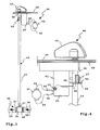
- eine Seitenansicht einer erfindungsgemäßen Boden-Reinigungsmaschine mit einer in gestrichelten Linien schematisch angedeuteten Schaltanordnung zum gekoppelten Schalten eines Ventils für eine Reinigungsflüssigkeit sowie eines Bürsten-Antriebs einer Bürste der Boden-Reinigungsmaschine,
- Figur 2
- eine perspektivische Ansicht der Boden-Reinigungsmaschine gemäß Figur 1 schräg von hinten,
- Figur 3
- eine hintere Ansicht der Schaltanordnung der Boden-Reinigungsmaschine gemäß Figur 1,
- Figur 4
- eine seitliche Detailansicht der Schaltanordnung gemäß Figur 3, und
- Figur 5
- die Schaltanordnung gemäß Figuren 3, 4 von oben.
- FIG. 1
- a side view of a floor cleaning machine according to the invention with a schematically indicated in dashed lines switching arrangement for coupled switching of a valve for a cleaning liquid and a brush drive of a brush of the floor cleaning machine,
- FIG. 2
- a perspective view of the floor cleaning machine according to Figure 1 obliquely from behind,
- FIG. 3
- a rear view of the switching arrangement of the floor cleaning machine according to Figure 1,
- FIG. 4
- a side detail view of the switching arrangement according to Figure 3, and
- FIG. 5
- the switching arrangement according to Figures 3, 4 from above.
Eine Boden-Reinigungsmaschine 10 zur Reinigung eines Bodens 11, beispielsweise eines Hartbelages, z.B. Stein, Fliesen, Kunststoff oder dergleichen, bringt Reinigungsflüssigkeit 12, z.B. Wasser mit einem optionalen Zusatz eines chemischen Reinigungsmittels, über einen Auslass 13 auf den Boden 11 aus. Eine Bürste 14, die durch einen Bürsten-Antrieb 15 angetrieben ist, reinigt den Boden 11 mit Hilfe der Reinigungsflüssigkeit 12. Die Bürste 14 ist vorliegend eine Teller-Bürste. An einem im wesentlichen kreisförmigen Bürstenteller 16 sind nach unten vorstehend Borsten 17 radial außen angeordnet, die den Boden 11 bürsten. Anstelle der Teller-Bürste 14 könnte auch eine Walzenbürste vorgesehen sein.A
Die auf den Boden 11 ausgebrachte Reinigungsflüssigkeit 12, die sogenannte Flotte, wird mit Hilfe einer Absauganordnung 18 im hinteren Bereich der Boden-Reinigungsmaschine 10 gesaugt. Die Absauganordnung 18 enthält eine langgestreckte, sich in Querrichtung der Boden-Reinigungsmaschine 10 erstreckende Absaugdüse 19, von der ein Absaugschlauch 20 in einen Schmutzwasserbehälter 21 im Innern eines Gehäuses 22 der Boden-Reinigungsmaschine 10 führt. Die Absaugdüse 19 ist hinten am Gehäuse 22 gelenkig mit Hilfe eines Gelenks 23 angeordnet. Die Absaugdüse 19 schwenkt in horizontaler Richtung um das Gelenk 23, beispielsweise um Kurvenbewegungen der Boden-Reinigungsmaschine 10 mitzumachen und ausgebrachte Reinigungsflüssigkeit 12 auch bei Kurvenfahrt möglichst breitbandig aufzunehmen. Seitliche Lenkrollen 24 sowie hinter der Absaugdüse 19 angebrachte Stützrollen 25 ermöglichen es, die Absaugdüse 19 an seitlichen Hindernissen vorbei bzw. über horizontale Hindernisse hinweg zu bewegen.The cleaning
Die Boden-Reinigungsmaschine 10 ist eine Hand-Reinigungsmaschine, die von einem Bediener mit Hilfe eines Handgriffs 26 geschoben und gelenkt werden kann. Der Handgriff 26 ist ein Bügel, der hinten am Gehäuse 22 zweckmäßigerweise horizontal schwenkbar angeordnet ist.The
Die Boden-Reinigungsmaschine 10 ist auf dem Boden 11 rollbar, wofür zwei vordere, im Bereich der Bürste 14 angeordnete nicht lenkbare Räder 30 sowie eines oder zwei hinter den Rädern 30 angeordnete lenkbare Räder 31 vorgesehen sind.The
Hinten an der Boden-Reinigungsmaschine 10 befinden sich ein Schmutzwasserablassschlauch 27 zum Ablassen von Schmutzwasser aus dem Schmutzwasserbehälter 21 sowie ein Frischwasser- oder Reinigungsflüssigkeitsschlauch 28, mit dem ein Vorratsbehälter 29 im Innern des Gehäuses 22 mit der Reinigungsflüssigkeit 12 befüllt werden kann.At the back of the
Mit Hilfe eines Pedals 32 kann die Höhe der Bürste 14 verstellt werden, das heißt die Bürste 14 kann auf den Boden 11 abgesenkt oder vom Boden 11 angehoben werden.With the help of a pedal 32, the height of the
Nach dem Öffnen eines zweckmäßigerweise schwenkbaren Deckels 33 sind der Schmutzwasserbehälter 21 und/oder der Vorratsbehälter 29 für die Reinigungsflüssigkeit 12 von oben her zugänglich, beispielsweise zum Reinigen, Entleeren oder Befüllen.After opening a suitably
Der Vorratsbehälter 29 ist oberhalb des Auslasses 13 angeordnet. Daher fließt die Reinigungsflüssigkeit 12 bedingt durch ihre Schwerkraft zum Auslass 13. Das Ventil 34 ist beispielsweise in einem unteren Bereich der Boden-Reinigungsmaschine angeordnet. Damit bei einem Stillstand der Boden-Reinigungsmaschine 10 nicht ständig Reinigungsflüssigkeit 12 aus dem Auslass 13 ausströmt, ist ein Ventil 34 in eine Fluidverbindung 35 zwischen dem Vorratsbehälter 29 und dem Auslass 13 geschaltet. Von dem Vorratsbehälter 29 führt eine Leitung 36 zum Ventil 34 und von dort führt eine Leitung 37 zum Auslass 13. Das Ventil 34 ist z.B. ein Kugelventil oder Kugelhahn. Das Ventil 34 ist z.B. durch eine Drehbewegung oder, nicht dargestellt, eine Schiebebewegung betätigbar.The
Damit ein Bediener die Boden-Reinigungsmaschine 10 bequem bedienen kann, sind die folgenden Maßnahmen vorgesehen:For an operator to conveniently operate the
Der Bediener schaltet mit Hilfe eines Hauptschalters 38 an einem Bedienfeld 39 die Boden-Reinigungsmaschine 10 an oder aus. Das Bedienfeld 39 ist beispielsweise hinten oben am Gehäuse 22 angeordnet, das heißt unterhalb des Handgriffes 26 und kann so leicht vom Bediener bedient werden. Die Boden-Reinigungsmaschine 10 ist ortsunabhängig, batteriebetrieben betreibbar. Eine nicht dargestellte Batterie an Bord der Boden-Reinigungsmaschine 10 stellt elektrische Energie bereit. Der Ladezustand der Batterie ist mit Hilfe einer Kontrollanzeige 40 am Bedienfeld 39 erkennbar, die ein Batteriesymbol, Leuchtdioden oder ähnliche Anzeigeelemente enthält, die den Ladezustand der nicht dargestellten Batterie repräsentieren.The operator turns on by means of a
Es versteht sich, dass die Boden-Reinigungsmaschine 10 auch als eine kabelgebundene Variante ausgeführt sein kann, die beispielsweise über ein elektrisches Anschlusskabel an ein elektrisches Versorgungsnetz anschließbar ist.It is understood that the
Mit dem Betätigen des Hauptschalters 38 wird ein in der Zeichnung nicht dargestellter Saugantrieb der Absauganordnung 18 eingeschaltet. Um den Reinigungsbetrieb der Boden-Reinigungsmaschine 10 dann vollends zu starten, muss der Bediener lediglich noch ein Bedienelement 41 betätigen, mit dem gekoppelt sowohl das Ventil 34 geöffnet als auch der Bürsten-Antrieb 15 gestartet wird.With the actuation of the
Das Bedienelement 41 ist vorliegend ein Drehschalter, der von einer in Figur 5 dargestellten Außerbetrieb-Stellung 42 in einen Arbeitsbereich 43 im Rahmen einer Inbetriebnahme-Bedienhandlung verstellbar ist. In dem Arbeitsbereich 43 ist das Ventil 34 geöffnet und der Bürsten-Antrieb 15 treibt die Bürste 14 rotatorisch an.In the present case, the operating
Das Bedienelement 41 ist Bestandteil einer Schaltanordnung 44 zum gekoppelten Schalten des Ventils 34 und eines Antriebsschalters 45 zum Schalten des Bürsten-Antriebs 15. Eine Kopplungsanordnung 46 überträgt eine Betätigungsbewegung des Bedienelements 41, das beispielsweise als eine Art Bedienknebel ausgestaltet ist, auf ein Betätigungsorgan 47 des Ventils 34. Das Betätigungsorgan 47 steht beispielsweise vor ein Gehäuse 48 des Ventils 34 nach oben vor und ist drehfest mit dem Bedienelement 41 gekoppelt, beispielsweise mit Hilfe einer Stange 49, die sich zwischen einem Drehzapfen 50 des Bedienelements 41 und dem Betätigungsorgan 47 erstreckt. Die Stange 49 ist beispielsweise an die Komponenten 41, 47 angeklebt, angeschweißt, aufgesteckt, aufgepresst, aufgeschrumpft oder in sonstiger Weise fest verbunden.The
Durch Bedienen des Bedienelements 41, vorliegend durch eine Drehbewegung von der Außerbetrieb-Stellung 42 in den Arbeitsbereich 43, wird die entsprechende Betätigungskraft über die Stange 49 auf das Betätigungsorgan 47 übertragen und somit das Ventil 34 geöffnet bzw. in umgekehrter Richtung geschlossen.By operating the operating
Innerhalb des Arbeitsbereiches 43 ist die von dem Ventil 34 durchgelassene Menge der Reinigungsflüssigkeit 12 stufenlos variierbar, was durch ein Symbol 51 am Bedienfeld 39 grafisch sichtbar wird. Das Ventil 34 ist ein Proportionalventil, wobei es durch ein vollständiges Schließen in der Außerbetrieb-Stellung 42 und ein vollständiges Öffnen am entgegengesetzten Ende des Arbeitsbereiches 43 auch die Funktion eines Sperrventiles erfüllt.Within the working
Der Bürsten-Antrieb 15 der Boden-Reinigungsmaschine 10 ist über den gesamten Arbeitsbereich 43 eingeschaltet. Dabei ist vorliegend eine im wesentlichen konstante Drehgeschwindigkeit der Bürste 14 vorgesehen, wobei auch eine stufenlose oder gestufte Drehgeschwindigkeitseinstellung, beispielsweise über den Arbeitsbereich 43 hinweg, denkbar ist.The
Bei der Boden-Reinigungsmaschine 10 ist sichergestellt, dass bei einer Inbetriebnahme-Bedienhandlung zunächst die Bürste 14 angetrieben wird, bevor das Ventil 34 geöffnet wird bzw. und in umgekehrter Richtung bei einer Außerbetriebnahme-Bedienhandlung zunächst das Ventil 34 geschlossen und der Durchfluss der Reinigungsflüssigkeit 12 unterbrochen wird, bevor der Bürsten-Antrieb 15 abgeschaltet wird. Dies ist folgendermaßen realisiert:In the
Das Ventil 34 ist zwischen einem Schließ-Endanschlag 52, bei dem es vollständig geschlossen ist, und einem Offen-Endanschlag 53, bei dem es vollständig geöffnet ist, verstellbar. Zur Vereinfachung sind die beiden Endanschläge 52, 53 an dem Bedienfeld 39 angedeutet. Zwischen dem Schließ-Endanschlag 52 und dem Beginn des Arbeitsbereiches 43 liegt ein Schließ-Stellweg 54 des Ventils 34, bei dem das Ventil 34 zumindest im wesentlichen geschlossen ist, zweckmäßigerweise vollständig geschlossen ist. Wenn ein Bediener das Bedienelement 41 vom Schließ-Endanschlag 52 weg in Richtung des Offen-Endanschlags 53 bewegt, ist das Ventil 34 zunächst noch geschlossen. Bereits auf dem Schließ-Stellweg 54 ist der Bürsten-Antrieb 15 aber bereits eingeschaltet, zumindest auf einem Teil des Schließ-Stellwegs 54.The
Die Schaltanordnung 44 enthält eine Steuerkurve 55, um den Antriebsschalter 45 gekoppelt, und der Offenstellung des Ventils 34 bei einer Inbetriebnahme-Bedienhandlung vorauseilend zu betätigen. Die Steuerkurve 55 ist an einem Steuerkörper 56 ausgebildet, der durch das Bedienelement 41 betätigt wird. Der Steuerkörper 56 ist beispielsweise im oberen Bereich der Stange 49 mittels einer Schraube 57 an dieser befestigt. Die Steuerkurve 55 betätigt bei einer Drehbewegung der Stange 49, das heißt beim Betätigen des Bedienelements 41, einen Betätigungshebel 58 des Antriebsschalters 45 unmittelbar oder zweckmäßigerweise über eine Rolle 59, die vorn am Betätigungshebel 58 angeordnet ist und auf der Steuerkurve 55 abrollt. Beim Drehen des Bedienelements 41 wird der Steuerkörper 56 mitgedreht und der Betätigungshebel 58 entsprechend der Steuerkurve 55 ausgelenkt. Dadurch wird der Antriebsschalter 45 betätigt und der Bürsten-Antrieb 15 ein- und ausgeschaltet.The
Der Bürsten-Antrieb 15 ist beispielsweise an Kontakte 60 des Antriebsschalters 45 unmittelbar oder über eine Ansteuerelektronik und/oder über ein Schaltrelais angeschlossen.The
Der Antriebsschalter 45 ist an einem Halter 61 angeordnet, beispielsweise mit einer Schraube 62 befestigt. Der Halter 61 erstreckt sich nach unten, etwa parallel zur Stange 49, von einem Halter 63 weg, an dessen Oberseite das Bedienfeld 39 ist. Das Bedienelement 41, insbesondere der Drehzapfen 50, durchdringt den beispielsweise plattenartigen Halter 63 und ist drehbar an dem Halter 63 gelagert. Von den Kontakten 60 führen Leitungen 64 zu dem Bürsten-Antrieb 15, z.B. einem Elektromotor.The
Denkbar wäre es auch, dass das Pedal 32 ein Bedienelement zur gekoppelten Betätigung des Ventils 34 und des Bürsten-Antriebs 15 ist, z.B. in der Art des Bedienelements 41. Beim Niederdrücken des Pedals 32 wird dann nicht nur die Bürste 14 auf den Boden 11 abgesenkt, sondern zudem der Bürsten-Antrieb 15 eingeschaltet und zweckmäßigerweise zeitlich etwas verzögert das Ventil 34 geöffnet. Sinngemäß derselbe Vorgang geschieht in umgekehrter Richtung, das heißt bei einer Außerbetriebnahme-Bedienhandlung, bei der das Pedal 32 wieder nach oben geht, insbesondere federkraftbehaftet. Zweckmäßigerweise wird dabei zunächst das Ventil 34 geschlossen, sodann die Bürste 14 vom Boden 11 abgehoben und der Bürsten-Antrieb 15 abgeschaltet.It would also be conceivable that the
Claims (30)
Applications Claiming Priority (1)
| Application Number | Priority Date | Filing Date | Title |
|---|---|---|---|
| DE202005011999U DE202005011999U1 (en) | 2005-07-30 | 2005-07-30 | Floor scrubbing machine has water outlet at center of rotating brush, flow of water being controlled by shut-off valve which is opened by switch which simultaneously switches on brush drive |
Publications (3)
| Publication Number | Publication Date |
|---|---|
| EP1749468A2 true EP1749468A2 (en) | 2007-02-07 |
| EP1749468A3 EP1749468A3 (en) | 2010-09-29 |
| EP1749468B1 EP1749468B1 (en) | 2012-03-14 |
Family
ID=35160827
Family Applications (1)
| Application Number | Title | Priority Date | Filing Date |
|---|---|---|---|
| EP06011888A Not-in-force EP1749468B1 (en) | 2005-07-30 | 2006-06-09 | Floor cleaning machine |
Country Status (3)
| Country | Link |
|---|---|
| EP (1) | EP1749468B1 (en) |
| AT (1) | ATE548958T1 (en) |
| DE (1) | DE202005011999U1 (en) |
Cited By (1)
| Publication number | Priority date | Publication date | Assignee | Title |
|---|---|---|---|---|
| CN105291112A (en) * | 2015-11-27 | 2016-02-03 | 深圳市神州云海智能科技有限公司 | Patrol robot |
Families Citing this family (7)
| Publication number | Priority date | Publication date | Assignee | Title |
|---|---|---|---|---|
| DE102005054499B4 (en) * | 2005-11-16 | 2007-08-23 | G. Staehle Gmbh U. Co. | Floor cleaning machine |
| DE102009006146A1 (en) * | 2009-01-26 | 2010-07-29 | Sandmaster Gesellschaft für Spielsandpflege und Umwelthygiene mbH | Mobile HD cleaning machine for outdoor plastic floors, and their application |
| DE102009024108A1 (en) | 2009-06-06 | 2010-12-09 | G. Staehle Gmbh U. Co. Kg | Floor cleaning machine |
| DE102013204398A1 (en) * | 2013-03-13 | 2014-09-18 | Hako Gmbh | Floor cleaning machine with a liquid supply device for the cleaning unit |
| DE202013103571U1 (en) | 2013-08-08 | 2013-09-05 | G. Staehle Gmbh U. Co. Kg | Floor cleaning machine |
| CN114000453B (en) * | 2021-12-06 | 2022-08-26 | 徐州三朋机械制造有限公司 | Side brush mechanism for sweeper |
| CN114747996B (en) * | 2022-05-20 | 2024-03-19 | 深圳赤马人工智能有限公司 | Intelligent floor washing robot |
Citations (1)
| Publication number | Priority date | Publication date | Assignee | Title |
|---|---|---|---|---|
| US3099028A (en) | 1961-09-01 | 1963-07-30 | Westinghouse Electric Corp | Surface treating appliance |
Family Cites Families (2)
| Publication number | Priority date | Publication date | Assignee | Title |
|---|---|---|---|---|
| US3940826A (en) * | 1973-10-12 | 1976-03-02 | Clarke-Gravely Corporation | Portable surface cleaner |
| DE3515791A1 (en) * | 1985-05-02 | 1986-11-06 | Ertl GmbH, 5485 Sinzig | Cleaning device |
-
2005
- 2005-07-30 DE DE202005011999U patent/DE202005011999U1/en not_active Expired - Lifetime
-
2006
- 2006-06-09 AT AT06011888T patent/ATE548958T1/en active
- 2006-06-09 EP EP06011888A patent/EP1749468B1/en not_active Not-in-force
Patent Citations (1)
| Publication number | Priority date | Publication date | Assignee | Title |
|---|---|---|---|---|
| US3099028A (en) | 1961-09-01 | 1963-07-30 | Westinghouse Electric Corp | Surface treating appliance |
Cited By (1)
| Publication number | Priority date | Publication date | Assignee | Title |
|---|---|---|---|---|
| CN105291112A (en) * | 2015-11-27 | 2016-02-03 | 深圳市神州云海智能科技有限公司 | Patrol robot |
Also Published As
| Publication number | Publication date |
|---|---|
| ATE548958T1 (en) | 2012-03-15 |
| DE202005011999U1 (en) | 2005-10-13 |
| EP1749468A3 (en) | 2010-09-29 |
| EP1749468B1 (en) | 2012-03-14 |
Similar Documents
| Publication | Publication Date | Title |
|---|---|---|
| EP1749468B1 (en) | Floor cleaning machine | |
| EP3206549B1 (en) | Surface cleaning machine having a damping device | |
| DE60202085T2 (en) | Carpet cleaner with two suction nozzles for two brush rolls | |
| EP3206548B1 (en) | Surface cleaning machine and method for operating a surface cleaning machine | |
| EP2470055B1 (en) | Handheld floor treatment device | |
| DE60223425T2 (en) | Mixing pump for a carpet cleaning tool | |
| EP0664973B1 (en) | Cleaning device for the shaving head of an electric razor | |
| DE19753668C2 (en) | Remote controllable vacuum cleaner | |
| DE69920858T2 (en) | Combination of recovery tank and suction nozzle for a vacuum cleaner | |
| EP1799091B1 (en) | Device for drying or wetting a mop | |
| DE3002422C2 (en) | Carpet cleaning device | |
| DE1455922A1 (en) | Device for washing vehicles | |
| DE2145633A1 (en) | Floor care machine | |
| EP1219225B1 (en) | Apparatus for moistening of mops | |
| DE20302630U1 (en) | Machine for steam scrubbing of floors has water pump heater scrubber drive and steam nozzles and can operate in three modes | |
| DE3309967A1 (en) | Floor-cleaning machine | |
| WO2009007123A2 (en) | Brush module | |
| DE3515791A1 (en) | Cleaning device | |
| EP4192318A1 (en) | Floor cleaning machine and method for operating a floor cleaning machine | |
| EP1343405A1 (en) | Device for cleaning a toilet seat | |
| DE653905C (en) | vacuum cleaner | |
| CH636297A5 (en) | DEVICE FOR DOSING AND MIXING LIQUID TWO-COMPONENT PLASTICS. | |
| EP3981312B1 (en) | Cleaning device | |
| DE3704080A1 (en) | Flushing-in device for liquid washing agents in a washing machine | |
| DE8122304U1 (en) | "Device for rinsing and disinfecting" |
Legal Events
| Date | Code | Title | Description |
|---|---|---|---|
| PUAI | Public reference made under article 153(3) epc to a published international application that has entered the european phase |
Free format text: ORIGINAL CODE: 0009012 |
|
| AK | Designated contracting states |
Kind code of ref document: A2 Designated state(s): AT BE BG CH CY CZ DE DK EE ES FI FR GB GR HU IE IS IT LI LT LU LV MC NL PL PT RO SE SI SK TR |
|
| AX | Request for extension of the european patent |
Extension state: AL BA HR MK YU |
|
| PUAL | Search report despatched |
Free format text: ORIGINAL CODE: 0009013 |
|
| AK | Designated contracting states |
Kind code of ref document: A3 Designated state(s): AT BE BG CH CY CZ DE DK EE ES FI FR GB GR HU IE IS IT LI LT LU LV MC NL PL PT RO SE SI SK TR |
|
| AX | Request for extension of the european patent |
Extension state: AL BA HR MK RS |
|
| 17P | Request for examination filed |
Effective date: 20101105 |
|
| AKX | Designation fees paid |
Designated state(s): AT BE BG CH CY CZ DE DK EE ES FI FR GB GR HU IE IS IT LI LT LU LV MC NL PL PT RO SE SI SK TR |
|
| GRAP | Despatch of communication of intention to grant a patent |
Free format text: ORIGINAL CODE: EPIDOSNIGR1 |
|
| GRAS | Grant fee paid |
Free format text: ORIGINAL CODE: EPIDOSNIGR3 |
|
| GRAA | (expected) grant |
Free format text: ORIGINAL CODE: 0009210 |
|
| AK | Designated contracting states |
Kind code of ref document: B1 Designated state(s): AT BE BG CH CY CZ DE DK EE ES FI FR GB GR HU IE IS IT LI LT LU LV MC NL PL PT RO SE SI SK TR |
|
| REG | Reference to a national code |
Ref country code: GB Ref legal event code: FG4D Free format text: NOT ENGLISH |
|
| REG | Reference to a national code |
Ref country code: CH Ref legal event code: EP Ref country code: AT Ref legal event code: REF Ref document number: 548958 Country of ref document: AT Kind code of ref document: T Effective date: 20120315 |
|
| REG | Reference to a national code |
Ref country code: IE Ref legal event code: FG4D Free format text: LANGUAGE OF EP DOCUMENT: GERMAN |
|
| REG | Reference to a national code |
Ref country code: DE Ref legal event code: R096 Ref document number: 502006011107 Country of ref document: DE Effective date: 20120510 |
|
| REG | Reference to a national code |
Ref country code: NL Ref legal event code: VDEP Effective date: 20120314 |
|
| PG25 | Lapsed in a contracting state [announced via postgrant information from national office to epo] |
Ref country code: LT Free format text: LAPSE BECAUSE OF FAILURE TO SUBMIT A TRANSLATION OF THE DESCRIPTION OR TO PAY THE FEE WITHIN THE PRESCRIBED TIME-LIMIT Effective date: 20120314 |
|
| LTIE | Lt: invalidation of european patent or patent extension |
Effective date: 20120314 |
|
| PG25 | Lapsed in a contracting state [announced via postgrant information from national office to epo] |
Ref country code: FI Free format text: LAPSE BECAUSE OF FAILURE TO SUBMIT A TRANSLATION OF THE DESCRIPTION OR TO PAY THE FEE WITHIN THE PRESCRIBED TIME-LIMIT Effective date: 20120314 Ref country code: GR Free format text: LAPSE BECAUSE OF FAILURE TO SUBMIT A TRANSLATION OF THE DESCRIPTION OR TO PAY THE FEE WITHIN THE PRESCRIBED TIME-LIMIT Effective date: 20120615 Ref country code: LV Free format text: LAPSE BECAUSE OF FAILURE TO SUBMIT A TRANSLATION OF THE DESCRIPTION OR TO PAY THE FEE WITHIN THE PRESCRIBED TIME-LIMIT Effective date: 20120314 |
|
| PGFP | Annual fee paid to national office [announced via postgrant information from national office to epo] |
Ref country code: FR Payment date: 20120705 Year of fee payment: 7 |
|
| PG25 | Lapsed in a contracting state [announced via postgrant information from national office to epo] |
Ref country code: CY Free format text: LAPSE BECAUSE OF FAILURE TO SUBMIT A TRANSLATION OF THE DESCRIPTION OR TO PAY THE FEE WITHIN THE PRESCRIBED TIME-LIMIT Effective date: 20120314 |
|
| PG25 | Lapsed in a contracting state [announced via postgrant information from national office to epo] |
Ref country code: SI Free format text: LAPSE BECAUSE OF FAILURE TO SUBMIT A TRANSLATION OF THE DESCRIPTION OR TO PAY THE FEE WITHIN THE PRESCRIBED TIME-LIMIT Effective date: 20120314 Ref country code: EE Free format text: LAPSE BECAUSE OF FAILURE TO SUBMIT A TRANSLATION OF THE DESCRIPTION OR TO PAY THE FEE WITHIN THE PRESCRIBED TIME-LIMIT Effective date: 20120314 Ref country code: SE Free format text: LAPSE BECAUSE OF FAILURE TO SUBMIT A TRANSLATION OF THE DESCRIPTION OR TO PAY THE FEE WITHIN THE PRESCRIBED TIME-LIMIT Effective date: 20120314 Ref country code: CZ Free format text: LAPSE BECAUSE OF FAILURE TO SUBMIT A TRANSLATION OF THE DESCRIPTION OR TO PAY THE FEE WITHIN THE PRESCRIBED TIME-LIMIT Effective date: 20120314 Ref country code: PL Free format text: LAPSE BECAUSE OF FAILURE TO SUBMIT A TRANSLATION OF THE DESCRIPTION OR TO PAY THE FEE WITHIN THE PRESCRIBED TIME-LIMIT Effective date: 20120314 Ref country code: IS Free format text: LAPSE BECAUSE OF FAILURE TO SUBMIT A TRANSLATION OF THE DESCRIPTION OR TO PAY THE FEE WITHIN THE PRESCRIBED TIME-LIMIT Effective date: 20120714 Ref country code: RO Free format text: LAPSE BECAUSE OF FAILURE TO SUBMIT A TRANSLATION OF THE DESCRIPTION OR TO PAY THE FEE WITHIN THE PRESCRIBED TIME-LIMIT Effective date: 20120314 |
|
| PG25 | Lapsed in a contracting state [announced via postgrant information from national office to epo] |
Ref country code: SK Free format text: LAPSE BECAUSE OF FAILURE TO SUBMIT A TRANSLATION OF THE DESCRIPTION OR TO PAY THE FEE WITHIN THE PRESCRIBED TIME-LIMIT Effective date: 20120314 Ref country code: PT Free format text: LAPSE BECAUSE OF FAILURE TO SUBMIT A TRANSLATION OF THE DESCRIPTION OR TO PAY THE FEE WITHIN THE PRESCRIBED TIME-LIMIT Effective date: 20120716 |
|
| BERE | Be: lapsed |
Owner name: G. STAEHLE G.M.B.H. U. CO. Effective date: 20120630 |
|
| PLBE | No opposition filed within time limit |
Free format text: ORIGINAL CODE: 0009261 |
|
| STAA | Information on the status of an ep patent application or granted ep patent |
Free format text: STATUS: NO OPPOSITION FILED WITHIN TIME LIMIT |
|
| PG25 | Lapsed in a contracting state [announced via postgrant information from national office to epo] |
Ref country code: DK Free format text: LAPSE BECAUSE OF FAILURE TO SUBMIT A TRANSLATION OF THE DESCRIPTION OR TO PAY THE FEE WITHIN THE PRESCRIBED TIME-LIMIT Effective date: 20120314 Ref country code: NL Free format text: LAPSE BECAUSE OF FAILURE TO SUBMIT A TRANSLATION OF THE DESCRIPTION OR TO PAY THE FEE WITHIN THE PRESCRIBED TIME-LIMIT Effective date: 20120314 Ref country code: MC Free format text: LAPSE BECAUSE OF NON-PAYMENT OF DUE FEES Effective date: 20120630 |
|
| REG | Reference to a national code |
Ref country code: CH Ref legal event code: PL |
|
| REG | Reference to a national code |
Ref country code: CH Ref legal event code: PL |
|
| 26N | No opposition filed |
Effective date: 20121217 |
|
| PG25 | Lapsed in a contracting state [announced via postgrant information from national office to epo] |
Ref country code: IT Free format text: LAPSE BECAUSE OF NON-PAYMENT OF DUE FEES Effective date: 20120609 |
|
| REG | Reference to a national code |
Ref country code: IE Ref legal event code: MM4A |
|
| REG | Reference to a national code |
Ref country code: DE Ref legal event code: R097 Ref document number: 502006011107 Country of ref document: DE Effective date: 20121217 |
|
| PG25 | Lapsed in a contracting state [announced via postgrant information from national office to epo] |
Ref country code: LI Free format text: LAPSE BECAUSE OF NON-PAYMENT OF DUE FEES Effective date: 20120630 Ref country code: IE Free format text: LAPSE BECAUSE OF NON-PAYMENT OF DUE FEES Effective date: 20120609 Ref country code: BE Free format text: LAPSE BECAUSE OF NON-PAYMENT OF DUE FEES Effective date: 20120630 Ref country code: CH Free format text: LAPSE BECAUSE OF NON-PAYMENT OF DUE FEES Effective date: 20120630 Ref country code: ES Free format text: LAPSE BECAUSE OF FAILURE TO SUBMIT A TRANSLATION OF THE DESCRIPTION OR TO PAY THE FEE WITHIN THE PRESCRIBED TIME-LIMIT Effective date: 20120625 |
|
| PG25 | Lapsed in a contracting state [announced via postgrant information from national office to epo] |
Ref country code: BG Free format text: LAPSE BECAUSE OF FAILURE TO SUBMIT A TRANSLATION OF THE DESCRIPTION OR TO PAY THE FEE WITHIN THE PRESCRIBED TIME-LIMIT Effective date: 20120614 |
|
| REG | Reference to a national code |
Ref country code: AT Ref legal event code: MM01 Ref document number: 548958 Country of ref document: AT Kind code of ref document: T Effective date: 20120609 |
|
| PG25 | Lapsed in a contracting state [announced via postgrant information from national office to epo] |
Ref country code: AT Free format text: LAPSE BECAUSE OF NON-PAYMENT OF DUE FEES Effective date: 20120609 |
|
| PGRI | Patent reinstated in contracting state [announced from national office to epo] |
Ref country code: IT Effective date: 20131025 |
|
| REG | Reference to a national code |
Ref country code: FR Ref legal event code: ST Effective date: 20140228 |
|
| PG25 | Lapsed in a contracting state [announced via postgrant information from national office to epo] |
Ref country code: TR Free format text: LAPSE BECAUSE OF FAILURE TO SUBMIT A TRANSLATION OF THE DESCRIPTION OR TO PAY THE FEE WITHIN THE PRESCRIBED TIME-LIMIT Effective date: 20120314 |
|
| PG25 | Lapsed in a contracting state [announced via postgrant information from national office to epo] |
Ref country code: FR Free format text: LAPSE BECAUSE OF NON-PAYMENT OF DUE FEES Effective date: 20130701 Ref country code: LU Free format text: LAPSE BECAUSE OF NON-PAYMENT OF DUE FEES Effective date: 20120609 |
|
| PG25 | Lapsed in a contracting state [announced via postgrant information from national office to epo] |
Ref country code: HU Free format text: LAPSE BECAUSE OF FAILURE TO SUBMIT A TRANSLATION OF THE DESCRIPTION OR TO PAY THE FEE WITHIN THE PRESCRIBED TIME-LIMIT Effective date: 20060609 |
|
| PGFP | Annual fee paid to national office [announced via postgrant information from national office to epo] |
Ref country code: IT Payment date: 20180622 Year of fee payment: 13 Ref country code: GB Payment date: 20180514 Year of fee payment: 13 |
|
| PGFP | Annual fee paid to national office [announced via postgrant information from national office to epo] |
Ref country code: DE Payment date: 20190429 Year of fee payment: 14 |
|
| GBPC | Gb: european patent ceased through non-payment of renewal fee |
Effective date: 20190609 |
|
| PG25 | Lapsed in a contracting state [announced via postgrant information from national office to epo] |
Ref country code: GB Free format text: LAPSE BECAUSE OF NON-PAYMENT OF DUE FEES Effective date: 20190609 Ref country code: IT Free format text: LAPSE BECAUSE OF NON-PAYMENT OF DUE FEES Effective date: 20190609 |
|
| REG | Reference to a national code |
Ref country code: DE Ref legal event code: R119 Ref document number: 502006011107 Country of ref document: DE |
|
| PG25 | Lapsed in a contracting state [announced via postgrant information from national office to epo] |
Ref country code: DE Free format text: LAPSE BECAUSE OF NON-PAYMENT OF DUE FEES Effective date: 20210101 |