EP1754438B1 - Endoscope, in particular duodendoscope for mother-baby- cholangioscopy - Google Patents
Endoscope, in particular duodendoscope for mother-baby- cholangioscopy Download PDFInfo
- Publication number
- EP1754438B1 EP1754438B1 EP06017240.0A EP06017240A EP1754438B1 EP 1754438 B1 EP1754438 B1 EP 1754438B1 EP 06017240 A EP06017240 A EP 06017240A EP 1754438 B1 EP1754438 B1 EP 1754438B1
- Authority
- EP
- European Patent Office
- Prior art keywords
- endoscope
- shaft
- port
- working channel
- inlet opening
- Prior art date
- Legal status (The legal status is an assumption and is not a legal conclusion. Google has not performed a legal analysis and makes no representation as to the accuracy of the status listed.)
- Active
Links
- 238000003780 insertion Methods 0.000 claims description 20
- 230000037431 insertion Effects 0.000 claims description 20
- 238000007789 sealing Methods 0.000 claims description 8
- 230000001154 acute effect Effects 0.000 claims description 3
- 230000000694 effects Effects 0.000 claims 1
- 239000000523 sample Substances 0.000 description 7
- 210000000013 bile duct Anatomy 0.000 description 4
- 210000001198 duodenum Anatomy 0.000 description 4
- 239000004809 Teflon Substances 0.000 description 3
- 229920006362 Teflon® Polymers 0.000 description 3
- 238000000034 method Methods 0.000 description 3
- 210000002784 stomach Anatomy 0.000 description 3
- 238000004026 adhesive bonding Methods 0.000 description 2
- 210000003445 biliary tract Anatomy 0.000 description 2
- 210000003238 esophagus Anatomy 0.000 description 2
- 210000003800 pharynx Anatomy 0.000 description 2
- 239000004033 plastic Substances 0.000 description 2
- 206010004637 Bile duct stone Diseases 0.000 description 1
- 238000002583 angiography Methods 0.000 description 1
- 238000005452 bending Methods 0.000 description 1
- 238000001574 biopsy Methods 0.000 description 1
- -1 biopsy forceps Substances 0.000 description 1
- 238000004140 cleaning Methods 0.000 description 1
- 230000000295 complement effect Effects 0.000 description 1
- 230000002950 deficient Effects 0.000 description 1
- 238000003745 diagnosis Methods 0.000 description 1
- 238000001839 endoscopy Methods 0.000 description 1
- 239000012530 fluid Substances 0.000 description 1
- 238000013467 fragmentation Methods 0.000 description 1
- 238000006062 fragmentation reaction Methods 0.000 description 1
- 238000002347 injection Methods 0.000 description 1
- 239000007924 injection Substances 0.000 description 1
- 230000002452 interceptive effect Effects 0.000 description 1
- 239000000463 material Substances 0.000 description 1
- 230000008774 maternal effect Effects 0.000 description 1
- 230000010412 perfusion Effects 0.000 description 1
- 230000002093 peripheral effect Effects 0.000 description 1
- 239000004575 stone Substances 0.000 description 1
Images


Classifications
-
- A—HUMAN NECESSITIES
- A61—MEDICAL OR VETERINARY SCIENCE; HYGIENE
- A61B—DIAGNOSIS; SURGERY; IDENTIFICATION
- A61B1/00—Instruments for performing medical examinations of the interior of cavities or tubes of the body by visual or photographical inspection, e.g. endoscopes; Illuminating arrangements therefor
- A61B1/012—Instruments for performing medical examinations of the interior of cavities or tubes of the body by visual or photographical inspection, e.g. endoscopes; Illuminating arrangements therefor characterised by internal passages or accessories therefor
- A61B1/018—Instruments for performing medical examinations of the interior of cavities or tubes of the body by visual or photographical inspection, e.g. endoscopes; Illuminating arrangements therefor characterised by internal passages or accessories therefor for receiving instruments
Definitions
- Such endoscopes find in endoscopy numerous applications.
- an instrument for example a catheter, a small so-called baby endoscope with a smaller diameter, etc., is usually inserted within an instrument channel of an already placed large endoscope extending from the proximal to the distal endoscope end in order to carry out an endoscopic examination or an intervention.
- a flexible endoscope (large duodenoscope) is placed in the usual ERCP technique on the papilla major (referred to as the papilla).
- the papilla a large portion of the duodenoscopic shaft must be inserted into the patient (pharynx, esophagus, stomach, duodenum) because the endoscope must be advanced along the receding curvature of the stomach into the duodenum.
- a stretching maneuver in which a large part of the shaft length is extracted until finally the duodenoscope is stretched on the papilla. After stretching, only about 60 cm of the anterior endoscope shaft are inserted into the patient. In this stretched position, both ERCP and mother-baby cholangioscopy are performed.
- the usual standard maternal-mother (mother-baby) cholangioscopy requires a (large) jumbo or mother duodenoscope and a baby cholangioscope insertable into the maternal duodenoscope.
- the baby endoscope is in this case introduced into the bile ducts via an opening in the endoscope housing or operating part of the instrumentation or working channel of the mother endoscope.
- the method is mainly used for the fragmentation of large bile duct stones, for example with a laser probe and the diagnosis of unclear bile duct findings.
- the baby endoscope is difficult or hardly maneuverable.
- many years of practice with frequent use shows a high repair liability of the baby endoscope, which is often defective after only a few uses.
- the present invention is therefore an object of the invention to improve this state of the art and to provide a duodenoscope and an assembly of a mother and baby endoscope, which avoid these disadvantages and ensure improved repairability with less susceptibility to repair.
- the shaft port Since the first input port, hereinafter referred to as shaft port, is located in a region of the shaft remote from the proximal end of the endoscope, the shaft port is located outside of the patient after extension, for example a few centimeters in front of his mouth, and can now be used as access into the instrumentation channel or working channel of the endoscope are used. As a result, a considerably shortened baby endoscope can be used because it is introduced via the shaft port and no longer via the usual (proximal) input or the proximal port of the Instrumentierkanals on the control panel of the endoscope.
- instruments such as a baby endoscope, a catheter, etc.
- a length of, for example, about 200 cm with a diameter of 3 to 4 mm to project beyond the shaft length of the parent endoscope now advantageously significantly shortened instruments, such as a baby endoscope be used by a length of only 90 to 140 cm, in particular 100 to 120 cm.
- the shortened instrument especially the shortened baby endoscope is better maneuverable, better rotatable than conventional longer instruments, and also the cleaning such a shorter instrument is facilitated.
- the bendability improves, which also reduces the cost of repair as a cost advantage.
- shortened instruments also include, for example, rotationally stable catheter of the angiographic catheter type, which are inserted into the bile ducts via the first entry opening or the shaft port in order to reach previously poor or inaccessible peripheral bile duct branches. While angiographic catheters introduced via normal duodenoscopes can no longer be rotated due to the great length, this is now possible due to the shortened path as a result of the shaft port or its shortened design.
- the various segments of the tree-like biliary system which otherwise can only be reached by long patient "poking" or untargeted probing with guidewires and catheters more or less randomly or not at all, can be targeted.
- the shaft port is located in the middle region of the shaft, in particular at a distance from the distal end of the endoscope of 60 to 70 cm.
- An instrument to be introduced therefore requires only a minimum length of, for example, 80 to 140 cm, preferably 120 cm, in order to project beyond the part of the shaft located in the patient after placement.
- the endoscope additionally has a further input opening in the form of a customary proximal port in the region of the proximal end or on the endoscope housing.
- the endoscope is additionally applicable as a normal endoscope, for example a duodenoscope, so that the costs for a separate acquisition of such an endoscope can be saved.
- the first and the further inlet opening or the shaft port and the proximal port can lead to one and the same working channel, wherein the working channel in this case extends to the proximal port.
- the working channel in this case extends to the proximal port.
- the shaft port is sealingly closable with a cover.
- a cover in the form of a fixed externally attachable lid, which preferably seals against both the working channel and the endoscope inside in the patch, for example, locked state.
- other possibilities are also conceivable for sealing the first input opening or the shaft port, in particular during the phase of the placement of the endoscope.
- a probe inserted into the endoscope channel via the conventional access on the operating part of the endoscope in particular a hollow probe (to allow further insufflation) which sealingly closes the shaft port from inside (inner cover) or through a closure sleeve, the opening thereof is closed by turning or shifting with respect to the shaft port opening (outer cover).
- a thin-walled rubber, plastic tube for example of the "fingerling" type with a cut-off tip
- an attachment with an insertion tube to facilitate the insertion of instruments in the working channel can be arranged fixed and removable on the shaft port an attachment with an insertion tube to facilitate the insertion of instruments in the working channel.
- This port attachment preferably seals the first entry port and the shaft port, respectively, so that air may not escape using a termination cap or gasket.
- the attachment can in this case be arranged on the shaft port or in this region of the shaft, so that the insertion in the cross-sectional profile laterally offset, for example 90 ° to 180 °, on the other side of a common proximal port comes to rest.
- the region of the endoscope shaft in which the shaft port is as a short, for example less than 10 cm, in particular 4 to 6 cm long, rigid (shaft) sleeve, for example in the form of a rigid outer shaft segment and a also rigid inner channel segment, formed.
- rigid (shaft) sleeve for example in the form of a rigid outer shaft segment and a also rigid inner channel segment, formed.
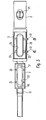
- first input port or the shaft port 1 of an endoscope is shown with an (outer) cover in the form of a lid 3.
- the shaft port 1 comprises a shaft segment in the form of an outer rigid sleeve 5 and a channel segment in Fonn a smaller diameter inner rigid sleeve 7, which serves for the passage of a working channel 9 of the endoscope and in cross-section ( Fig. 1c ) is not concentric, but is arranged near the inner wall of the shaft segment 5.
- both the shaft segment 5 and the channel segment 7 preferably have mutually aligned elongate openings 25, 27 (FIG. Fig. 3 ) on
- the access to the working channel realized in this way 9 can be like in Fig. 1b illustrated an insertion aid in the form of an outwardly widening chamfer 49 to facilitate the insertion of an instrument in the working channel 9.
- an inwardly widening slant or insertion aid 51 may be located to facilitate the oblique insertion of an instrument obliquely from the upper left into the working channel 9, which leads to the right towards the distal end. In this way, advantageously, even with a short shaft port 1 or first input port of, for example, 15-30 mm, an easy insertion of an instrument can be ensured.
- the channel segment 7 has two connecting pieces 11 and 13, on which the ends of the working channel 9 pushed and possibly additionally, for example by gluing, can be fixed.
- the shaft segment 5 is in the endoscope shaft 15, which in Fig. 1a and Fig. 1b dashed lines, fixed, for example, by gluing, aligned, so that despite the preferred rigid design of the entire shaft port 1 on the outer surface of the endoscope shaft 15 no undesirable attack sites, such as steps, edges, etc. form as slip obstacle.
- the thin lid 3 closes the shaft port 1 or the first input opening, with a projecting area 17 on the underside of the lid 3 into the elongated opening 25 of the shaft segment 5 and possibly even in FIG the hereby aligned opening 27 of the channel segment 7 preferably protrudes accurately.
- an actuating element for example in the form of a slotted screw 21 of a locking device is actuated, wherein the locking device consists for example of a locking element 19.
- This locking element 19 is oval-shaped on the underside of the screw 21, wherein only in the locked state opposite extensions 19a and 19b of the substantially oval disc 19 engage in corresponding recesses of the channel segment 7.
- the lid 3 alsklippbar, wherein it is formed in profile, for example, as a projecting beyond the shank circumference half, or encompassing half-shell.
- the protruding region 17 can in any case be designed to be flush in addition to the channel interior, so that, in the closed state, advantageously no unwanted resistances result for an instrument introduced via the proximal port 63.
- the shaft port 1 of a channel segment 7 and the shaft segment 5 is constructed such that, as out Fig. 1c can be seen, the channel segment is arranged with its opening 27 on the inside of the shaft segment 5 in the region of the opening 25.
- the channel segment 7 may have in cross-section a semicircular on the outer surface extension, in which threaded holes 35 are provided. In the assembled state, these holes 35 are aligned with holes 33 in the shaft segment 5, so that the channel segment 7 can be fixed to the shaft segment 5 by means of screws 31. In this way, the opening 25 of the shaft segment 5 go with their bevels 49 and 51 and the opening 27 of the channel segment 7 in alignment with each other.
- a seal (not shown in detail in the drawing) is provided between the outer surface of the channel segment 7, surrounding the opening 27, which sealingly bears against the inner side of the shaft segment 5. Furthermore, on the outer surface of the shaft segment 5, a circumferential around the opening 25 seal 29 is arranged in the region of the underside of the lid 3, so that the lid 3 in the locked state also sealingly closes.
- one or more elongated spring elements 23a and 23b may additionally be provided on both longitudinal sides of the cover 3 (or the corresponding complementary recess of the shaft port 1) be arranged, which are pre-bent so that they extend in the closing state oblong and their spring force acts against the placement of the lid 3.
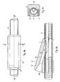
- Fig. 4a is shown as a port attachment 37, which is for example made as a milled part or injection molded part, is placed on the shaft port 1 to allow through an opening 39, the insertion of an instrument in the distal direction (in the drawing to the right) in the working channel 9.
- the port attachment 37 is in this case plugged through the lateral opening 25, 27 on the shaft port 1 of the mother endoscope shaft 15.
- a seal (“O" ring, rubber plate, etc.) (not shown in detail in the drawing) (not shown in detail in the drawing) can be provided between shaft port 1 and port attachment 37 in order to prevent air from escaping between port attachment 37 and shaft port 1.
- Fig. 4c is the port attachment 37 from a lower shell 41 and an upper shell 43, in which the funnel-shaped outwardly widening opening 39 and just adjoining Ein Industriesstutzen 40 are constructed.
- two fastening elements 45 and 47 for example in the form of locking pins or screws can be arranged, which of course also a hinge on one side and arranged on the opposite side lock, for example in the form of a hook, conceivable is.
- Fig. 4b shown leads the straight tubular inlet tube 40 from top left to obliquely bottom right at a shallow angle in the working channel 9 in the distal direction (right side in the drawing) into it, said guide through by on the short sides of the elongated openings 25 and 27 into one another transitional bevels 49 and 51 is supported.
- the insertion tube 40 in this case has a relation to the inner diameter of the working channel (for example, 4.2 mm) smaller or the same inner diameter.
- the port attachment 37 protrudes at this point with its corresponding to the opening 25 formed material 53, so that a spatially and rotationally fixed arrangement and centering of the port attachment 37 is ensured at the shaft port 1 by this intermeshing intervention.
- insertion aids 49, 51 even with a desired short length of the shaft port 1 and the shaft and channel segments 5 and 7 of 40 to 60 mm and a realized through the openings 25, 27 short shaft port opening of only 15 to 30 mm in length as possible flat or acute angle (as seen from the proximal end) between the longitudinal axis of the insertion and the longitudinal axis of the working channel 9 and the endoscope shaft 15, for example, 10 to 40 degrees, preferably from 10 to 20 degrees.
- the insertion tube 40 or the opening 39 can be closed with a sealing cap (not shown in detail in the drawing) (also for the sealing introduction of instruments).
- the shaft port 1 or the port attachment 37 is arranged in a mother or mother duodenoscope 61 shown here.
- the shaft port 1, which is 40 to 60 mm long and integrated in the shaft 15, is located approximately between 60 and 70 cm away from the distal head end of the endoscope 61.
- the elongate opening of the shaft port 1 has, for example, a diameter of 3.5 mm thick baby endoscope a length of about 15 to 30 mm.
- the shaft port 1 or port attachment 37 is arranged with its opening 39 in the longitudinal direction at the proximal end or the operating part of the endoscope from the left side, whereas a conventional, proximal port 63 is usually arranged on the right side of the control unit.
- a conventional, proximal port 63 is usually arranged on the right side of the control unit.
- Fig. 6 is also greatly simplified indicated that the port attachment instead of bivalve, for example, in the cross-sectional profile can be U-shaped. Moreover, in Fig. 6 another type of attachment, namely, for example by means of an insertable into the ends of the U-shaped leg screw or axle with an eccentric which clamps the port attachment to the shaft or the shaft port when actuated by rotation, indicated.
- the shaft port 1 must be closed, since in this case approximately 100 to 110 cm of the endoscope shaft and thus the shaft port itself are located inside a patient. This can be achieved, for example, by a cover 3 which can be inserted into the shaft port opening, as explained above.
- inner or outer covers such as, for example, a conventional proximal access or port 63 on the operating part of the endoscope into the endoscope channel 9 inserted hollow probe, which closes the shaft port 1 from the inside sealing, a closure sleeve, the opening is closed by turning or moving relative to the shaft port opening or a thin-walled rubber, plastic hose (type Fingerling with truncated dome) pushed onto the duodenoscope, on the shaft port opening is rolled, conceivable.
- a conventional proximal access or port 63 on the operating part of the endoscope into the endoscope channel 9 inserted hollow probe which closes the shaft port 1 from the inside sealing, a closure sleeve, the opening is closed by turning or moving relative to the shaft port opening or a thin-walled rubber, plastic hose (type Fingerling with truncated dome) pushed onto the duodenoscope, on the shaft port opening is rolled, conceivable.
- the shaft port 1 comes to lie outside the patient, as a result of the extension, only one shaft length of less than 60 cm remains in the patient.
- the shaft port 1 can then be used as access for instruments.
- the port attachment 37 is sealed against the respective instrument, for example an inserted baby endoscope (for example by means of a corresponding seal in the port attachment 37 or its opening, in order to prevent injected air from escaping during introduction as far as the duodenum and thus by collapsing the lumen
- a stronger air supply preferably has to take place in order to compensate for the possibly escaping air via the shaft port 1.
- the port attachment 37 is introduced via the shaft port 1 into the instrumentation channel or working channel 9 and seals it. At the outer end can also be attached a side nozzle for air insufflation. This nozzle may eventually be connected to the normal air supply.
- the port attachment 37 in principle as a very thin-walled (Teflon etc.) hose, which is inserted through the shaft port 1 in the working channel 9 substantially sealing.
- Teflon etc. very thin-walled
- the fixation of the port attachment 37 on the shaft 15 can by various ways, such as an eccentric (screw, lever o. ⁇ .) With the port attachment 37 is clamped done.
- the port attachment 37 is preferably equipped with centering means, such as by the above-mentioned projection, centering pins o. ⁇ ., And fixed on the shaft port 1, that the insertion tube 40 opens optimally in the Instrumentierkanal 9 and thus the baby endoscope optimally with the least possible friction can be inserted into the mother endoscope 61.
- Such a baby endoscope for example, has an outer diameter of about 3.5 mm and thus has about 0.5 mm clearance (for example for insufflation) to the instrumentation channel (diameter about 4 mm) of the parent endoscope.
- the outer skin of the baby endoscope is designed to be as slippery as possible (teflon, etc.) in order to provide low sliding resistance.
- the baby endoscope is preferably as stable as possible to rotation, so that the missing bending planes can be achieved by rotation.
- the baby endoscope has an instrumentation channel of at least 1 mm (preferably at least 1.4 mm), so that it is suitable for electrohydraulic probes, biopsy forceps, stone baskets, etc.
- an endoscope in particular a duodenoscope
- the endoscope can in principle also be used as a routine endoscope, in particular a duodenoscope, for example for conventional ERCP, so that not two duodenoscopes are used for the ERCP operation required are. This can be advantageously (especially in smaller clinics with limited budget) costs saved.
Description
Derartige Endoskope, wie beispielsweise in dem
So wird beispielsweise bei der peroralen transpapillären Cholangioskopie zunächst ein flexibles Mutterendoskop (großes Duodenoskop) in der üblichen ERCP Technik an der Papilla major (im Weiteren Papille genannt) platziert. Zum Erreichen der Papille muss ein großer Teil des Duodenoskop-Schaftes in den Patienten (Schlund, Speiseröhre, Magen, Zwölffingerdarm)) eingeführt werden, weil das Endoskop entlang der zurückweichenden Kurvatur des Magens in das Duodenum vorgeschoben werden muss. Danach erfolgt ein Streckmanöver, bei dem ein großer Teil der Schaftlänge extrahiert wird, bis schließlich das Duodenoskop gestreckt an der Papille liegt. Nach der Streckung sind nur noch etwa 60 cm des vorderen Endoskopschaftes in den Patienten eingeführt. In dieser gestreckten Position werden sowohl ERCP als auch Mother-Baby-Cholangioskopie durchgeführt.For example, in the case of peroral transpapillary cholangioscopy, a flexible endoscope (large duodenoscope) is placed in the usual ERCP technique on the papilla major (referred to as the papilla). To reach the papilla, a large portion of the duodenoscopic shaft must be inserted into the patient (pharynx, esophagus, stomach, duodenum) because the endoscope must be advanced along the receding curvature of the stomach into the duodenum. This is followed by a stretching maneuver in which a large part of the shaft length is extracted until finally the duodenoscope is stretched on the papilla. After stretching, only about 60 cm of the anterior endoscope shaft are inserted into the patient. In this stretched position, both ERCP and mother-baby cholangioscopy are performed.
Die bisher übliche Standard-Mutter-Baby- (Mother-Baby)-Cholangioskopie erfordert ein (großes) Jumbo- bzw. Mutter-Duodenoskop und ein in das Mutter-Duodenoskop einführbares Baby-Cholangioskop. Das Babyendoskop wird hierbei über eine am Endoskopgehäuse bzw. Bedienteil befindliche Öffnung des Instrumentier- bzw. Arbeitskanals des Mutterendoskops in die Gallenwege eingeführt. Die Methode dient vorwiegend der Fragmentierung von großen Gallengangssteinen, beispielsweise mit einer Lasersonde und der Diagnostik unklarer Gallengangsbefunde.The usual standard maternal-mother (mother-baby) cholangioscopy requires a (large) jumbo or mother duodenoscope and a baby cholangioscope insertable into the maternal duodenoscope. The baby endoscope is in this case introduced into the bile ducts via an opening in the endoscope housing or operating part of the instrumentation or working channel of the mother endoscope. The method is mainly used for the fragmentation of large bile duct stones, for example with a laser probe and the diagnosis of unclear bile duct findings.
Nachteiligerweise ist bei diesem bekannten Instrumentarium und Verfahren das Babyendoskop nur schwer oder kaum mehr manövrierbar. Darüber hinaus zeigt sich in der jahrelangen Praxis bei häufiger Anwendung eine hohe Reparaturanfälligkeit des Babyendoskops, welches häufig bereits nach wenigen Einsätzen defekt ist.Disadvantageously, in this known instrumentation and method, the baby endoscope is difficult or hardly maneuverable. In addition, many years of practice with frequent use shows a high repair liability of the baby endoscope, which is often defective after only a few uses.
Der vorliegenden Erfindung liegt daher die Aufgabe zugrunde, diesen Stand der Technik zu verbessern und ein Duodenoskop sowie eine Anordnung aus einem Mutter- und Babyendoskop zu schaffen, welche diese Nachteile vermeiden und bei verbesserter Manövrierbarkeit eine geringere Reparaturanfälligkeit gewährleisten.The present invention is therefore an object of the invention to improve this state of the art and to provide a duodenoscope and an assembly of a mother and baby endoscope, which avoid these disadvantages and ensure improved repairability with less susceptibility to repair.
Diese Aufgabe wird erfindungsgemäß mit einem Duodenoskop mit den Merkmalen des Anspruchs 1 sowie einer Anordnung aus einem solchen Endoskop mit einem Babyendoskop mit den Merkmalen des Anspruchs 9 gelöst. Ein Endoskop mit einen vom proximalen Ende entfernten Eingangsöffnung ist aus Dokument
Da sich die erste Eingangsöffnung, im Folgenden Schaftport genannt, in einem vom proximalen Ende des Endoskops entfernten Bereich des Schaftes befindet, liegt der Schaftport nach einer erfolgten Streckung außerhalb des Patienten, beispielsweise einige Zentimeter vor seinem Mund, und kann jetzt als Zugang in den Instrumentierkanal bzw. Arbeitskanal des Endoskops benutzt werden. Dadurch kann ein erheblich verkürztes Babyendoskop verwendet werden, weil es über den Schaftport und nicht mehr über den sonst üblichen (proximalen) Eingang bzw. den proximalen Port des Instrumentierkanals am Bedienteil des Endoskops eingeführt wird. Statt Instrumenten, wie beispielsweise einem Babyendoskop, einem Katheter etc., welche eine Länge von beispielsweise ca. 200 cm bei einem Durchmesser von 3 bis 4 mm erfordern, um die Schaftlänge des Mutterendoskops zu überragen, können nun vorteilhafterweise wesentlich verkürzte Instrumente, beispielsweise ein Babyendoskop von einer Länge von nur 90 bis 140 cm, insbesondere 100 bis 120 cm verwendet werden.Since the first input port, hereinafter referred to as shaft port, is located in a region of the shaft remote from the proximal end of the endoscope, the shaft port is located outside of the patient after extension, for example a few centimeters in front of his mouth, and can now be used as access into the instrumentation channel or working channel of the endoscope are used. As a result, a considerably shortened baby endoscope can be used because it is introduced via the shaft port and no longer via the usual (proximal) input or the proximal port of the Instrumentierkanals on the control panel of the endoscope. Instead of instruments, such as a baby endoscope, a catheter, etc., which require a length of, for example, about 200 cm with a diameter of 3 to 4 mm to project beyond the shaft length of the parent endoscope, now advantageously significantly shortened instruments, such as a baby endoscope be used by a length of only 90 to 140 cm, in particular 100 to 120 cm.
Das verkürzte Instrument, insbesondere das verkürzte Babyendoskop ist besser manövrierbar, besser drehbar als herkömmliche längere Instrumente, wobei auch die Reinigung eines solchen kürzeren Instruments erleichtert wird. Zudem verbessert sich die Abwinkelbarkeit, wobei sich als Kostenvorteil auch die Reparaturanfälligkeit verringert.The shortened instrument, especially the shortened baby endoscope is better maneuverable, better rotatable than conventional longer instruments, and also the cleaning such a shorter instrument is facilitated. In addition, the bendability improves, which also reduces the cost of repair as a cost advantage.
Als verkürzte Instrumente kommen hierbei neben einem Babyendoskop (Cholangioskop, Pankreatikoskop) beispielsweise auch drehstabile Katheter vom Typ Angiografiekatheter in Frage, welche über die erste Eingangsöffnung bzw. den Schaftport in die Gallenwege eingeführt werden, um bisher schlecht oder gar nicht zugängliche periphere Gallengangsäste zu erreichen. Während sich über normale Duodenoskope eingeführte Angiografiekatheter infolge der großen Länge nicht mehr drehen lassen, ist dies nunmehr durch die infolge des Schaftports verkürzte Strecke bzw. deren verkürzte Ausbildung möglich. So lassen sich die verschiedenen Segmente des baumartigen biliären Systems, die sonst nur durch langes geduldiges "Stochern" bzw. ungezieltes Sondieren mit Führungsdrähten und Kathetern mehr oder weniger zufällig oder auch gar nicht erreicht werden können, gezielt sondieren.In addition to a baby endoscope (cholangioscope, pancreaticoscope), shortened instruments also include, for example, rotationally stable catheter of the angiographic catheter type, which are inserted into the bile ducts via the first entry opening or the shaft port in order to reach previously poor or inaccessible peripheral bile duct branches. While angiographic catheters introduced via normal duodenoscopes can no longer be rotated due to the great length, this is now possible due to the shortened path as a result of the shaft port or its shortened design. Thus, the various segments of the tree-like biliary system, which otherwise can only be reached by long patient "poking" or untargeted probing with guidewires and catheters more or less randomly or not at all, can be targeted.
Nach der Erfindung liegt der Schaftport im mittleren Bereich des Schaftes, insbesondere in einer Entfernung vom distalen Ende des Endoskops von 60 bis 70 cm. Hierdurch kann bei besonderen Untersuchungen, insbesondere der Cholangioskopie, gewährleistet werden dass die erste Öffnung außerhalb des Patienten, aber doch nahe seinem Mund zu liegen kommt. Ein einzuführendes Instrument bedarf daher nur einer Mindestlänge von beispielsweise 80 bis 140 cm, vorzugsweise 120 cm, um den nach der Platzierung in dem Patienten befindlichen Teil des Schaftes zu überragen.According to the invention, the shaft port is located in the middle region of the shaft, in particular at a distance from the distal end of the endoscope of 60 to 70 cm. In this way, in the case of special examinations, in particular cholangioscopy, it can be ensured that the first opening comes to lie outside the patient, but nevertheless close to his mouth. An instrument to be introduced therefore requires only a minimum length of, for example, 80 to 140 cm, preferably 120 cm, in order to project beyond the part of the shaft located in the patient after placement.
In bevorzugter Ausgestaltung der Erfindung weist das Endoskop zusätzlich im Bereich des proximalen Endes bzw. am Endoskopgehäuse eine weitere Eingangsöffnung in Form eines üblichen proximalen Ports auf. Hierdurch ist das Endoskop zusätzlich als normales Endoskop, beispielsweise Duodenoskop anwendbar, so dass die Kosten für eine gesonderte Anschaffung eines solchen Endoskops eingespart werden können.In a preferred embodiment of the invention, the endoscope additionally has a further input opening in the form of a customary proximal port in the region of the proximal end or on the endoscope housing. As a result, the endoscope is additionally applicable as a normal endoscope, for example a duodenoscope, so that the costs for a separate acquisition of such an endoscope can be saved.
Hierbei können die erste und die weitere Eingangsöffnung bzw. der Schaftport und der proximale Port zu ein und demselben Arbeitskanal führen, wobei sich der Arbeitskanal hierbei bis zum proximalen Port erstreckt. Hierdurch kann vorteilhafterweise ein zusätzlicher separater Arbeitskanal vermieden werden, welcher sonst möglicherweise zu einer unerwünschten Erhöhung des Schaftdurchmessers des Endoskops führt.Here, the first and the further inlet opening or the shaft port and the proximal port can lead to one and the same working channel, wherein the working channel in this case extends to the proximal port. In this way, advantageously, an additional separate working channel can be avoided, which may otherwise lead to an undesirable increase in the shaft diameter of the endoscope.
In weiterer Ausgestaltung der Erfindung ist der Schaftport mit einer Abdeckung dichtend verschließbar ausgebildet. Dies kann beispielsweise durch eine Abdeckung in Form eines von außen ortsfest anbringbaren Deckels erfolgen, welcher vorzugsweise sowohl gegenüber dem Arbeitskanal als auch zum Endoskopinneren im aufgesetzten, beispielsweise verriegelten Zustand dichtet. Selbstverständlich sind auch andere Möglichkeiten denkbar, um die erste Eingangsöffnung bzw. den Schaftport vor allem während der Phase der Platzierung des Endoskops dichtend zu verschließen. Dies kann beispielsweise erreicht werden durch eine über den konventionellen Zugang am Bedienteil des Endoskops in den Endoskopkanal eingeführte Sonde, insbesondere Hohlsonde (um eine weiter Insufflation zu ermöglichen), die den Schaftport von innen (innere Abdeckung) dichtend schließt oder durch eine Verschlusshülse, deren Öffnung durch Drehen oder Verschieben gegenüber der Schaftport-Öffnung (äußere Abdeckung) geschlossen wird. Auch ist es denkbar einen dünnwandigen Gummi-, Kunststoffschlauch (beispielsweise des Typs "Fingerling" mit abgeschnittener Kuppe) zu verwenden, der auf das Duodenoskop aufgeschoben, über die Schaftportöffnung (äußere Abdeckung) abgerollt wird.In a further embodiment of the invention, the shaft port is sealingly closable with a cover. This can be done for example by a cover in the form of a fixed externally attachable lid, which preferably seals against both the working channel and the endoscope inside in the patch, for example, locked state. Of course, other possibilities are also conceivable for sealing the first input opening or the shaft port, in particular during the phase of the placement of the endoscope. This can be achieved, for example, by a probe inserted into the endoscope channel via the conventional access on the operating part of the endoscope, in particular a hollow probe (to allow further insufflation) which sealingly closes the shaft port from inside (inner cover) or through a closure sleeve, the opening thereof is closed by turning or shifting with respect to the shaft port opening (outer cover). It is also conceivable to use a thin-walled rubber, plastic tube (for example of the "fingerling" type with a cut-off tip), which is pushed onto the duodenoscope and unrolled over the shaft port opening (outer cover).
In weiterer Ausgestaltung der Erfindung kann an dem Schaftport ein Aufsatz mit einem Einführstutzen ortsfest und abnehmbar angeordnet werden, um das Einführen von Instrumenten in den Arbeitskanal zu erleichtern. Dieser Portaufsatz dichtet vorzugsweise die erste Eingangsöffnung bzw. den Schaftport ab, so dass eventuell unter Verwendung einer Abschlusskappe oder Dichtung keine Luft entweichen kann. Der Aufsatz kann hierbei derart an dem Schaftport bzw. in diesem Bereich des Schaftes angeordnet werden, so dass der Einführstutzen im Querschnittsprofil seitlich versetzt, beispielsweise um 90° bis 180°, auf der anderen Seite eines üblichen proximalen Ports zum Liegen kommt. Hierdurch kann vorteilhafterweise vermieden werden, dass sich Bedienpersonal und Arzt während einer Behandlung gegenseitig behindern, da nunmehr zum Hantieren bzw. Einführen und Bedienen eines Instruments die gegenüberliegende Seite (also beispielsweise links vom Bedienteil aus gesehen) des üblicherweise (in der Regel rechtsseitigen) proximalen Ports verwendet wird.In a further embodiment of the invention can be arranged fixed and removable on the shaft port an attachment with an insertion tube to facilitate the insertion of instruments in the working channel. This port attachment preferably seals the first entry port and the shaft port, respectively, so that air may not escape using a termination cap or gasket. The attachment can in this case be arranged on the shaft port or in this region of the shaft, so that the insertion in the cross-sectional profile laterally offset, for example 90 ° to 180 °, on the other side of a common proximal port comes to rest. As a result, it can be advantageously avoided that the operating personnel and the physician interfere with one another during a treatment, since the opposite side (ie, for example, on the left side of the operating part) of the usually (usually right-sided) proximal ports is now used for handling or inserting and operating an instrument is used.
In bevorzugter Ausgestaltung der Erfindung ist der Bereich des Endoskopschaftes, in welchem sich der Schaftport befindet, als kurze, beispielsweise kleiner als 10 cm, insbesondere 4 bis 6 cm lange, starre (Schaft-)Hülse, beispielsweise in Form eines starren äußeren Schaftsegmentes und eines ebenfalls starren inneren Kanalsegmentes, ausgebildet. Hierdurch erhöht sich vorteilhafterweise trotz guter Flexibilität des gesamten Endoskopschaftes die Stabilität und Passgenauigkeit des Schaftports, so dass an dieser leichter eine Abdeckung in Form eines einsetzbaren Deckels oder ein Portaufsatz mit einem möglichst zum Arbeitskanal flachen Einführwinkel dichtend und ortsfest angeordnet werden kann.In a preferred embodiment of the invention, the region of the endoscope shaft in which the shaft port is as a short, for example less than 10 cm, in particular 4 to 6 cm long, rigid (shaft) sleeve, for example in the form of a rigid outer shaft segment and a also rigid inner channel segment, formed. This advantageously increases despite good flexibility of the entire endoscope shaft stability and accuracy of the shaft port, so that at this easier a cover in the form of an insertable lid or a port attachment with a possible flat to the working channel insertion angle sealing and can be arranged stationary.
Weitere vorteilhafte Ausgestaltungen der Erfindung ergeben sich aus den UnteransprüchcnFurther advantageous embodiments of the invention will become apparent from the Unteransprüchcn
Die Erfindung wird nachfolgend anhand in der Zeichnung dargestellter Ausführungsbeispiele näher erläutert. In der Zeichnung zeigen:
-
Fig. 1a eine Seitenansicht eines Schaftports eines Endoskops nach der Erfindung mit Deckel und Arbeitskanal; -
Fig. 1b eine Schnittansicht des Schaftports nachFig. 1a entlang der Linie A-A; -
Fig. 1c eine Schnittansicht des Schaftports nachFig. 1a entlang der Linie B-B; -
Fig. 2a eine Unteransicht eines Deckels; -
Fig. 2b eine Schnittansicht des Deckels nachFig. 2a entlang der Linie C-C; -
Fig. 3 eine Explosionsdarstellung eines Schaftports nachFig. 1a : -
Fig. 4a eine Seitenansicht des Schaftports mit Portaufsatz; -
Fig. 4b eine Schnittansicht des Schaftports nachFig. 4a entlang der Linie E-E; -
Fig. 4c eine Schnittansicht des Schaftports nachFig. 4a entlang der Linie D-D; -
Fig. 5 eine Seitenansicht eines erfindungsgemäßen Endoskops und -
Fig. 6 ein schematischer Querschnitt durch das Endoskop nachFig. 5 entlang der Linie F-F
-
Fig. 1a a side view of a shaft port of an endoscope according to the invention with cover and working channel; -
Fig. 1b a sectional view of the shaft port afterFig. 1a along the line AA; -
Fig. 1c a sectional view of the shaft port afterFig. 1a along the line BB; -
Fig. 2a a bottom view of a lid; -
Fig. 2b a sectional view of the lid afterFig. 2a along the line CC; -
Fig. 3 an exploded view of a shaft port afterFig. 1a : -
Fig. 4a a side view of the shaft port with port attachment; -
Fig. 4b a sectional view of the shaft port afterFig. 4a along the line EE; -
Fig. 4c a sectional view of the shaft port afterFig. 4a along the line DD; -
Fig. 5 a side view of an endoscope according to the invention and -
Fig. 6 a schematic cross section through the endoscope afterFig. 5 along the line FF
Die in
Um eine in den Arbeitskanal 9 reichende Öffnung zu realisieren weisen sowohl Schaftscgment 5 als auch Kanalsegment 7 vorzugsweise zueinander fluchtende längliche Öffnungen 25, 27 (
Zum beidseitigen Anschluss an den als Teflonschlauch ausgebildeten Arbeitskanal 9 weist das Kanalsegment 7 zwei Anschlussstutzen 11 und 13 auf, auf welche die Enden des Arbeitskanals 9 aufgeschoben und eventuell zusätzlich, beispielsweise durch Verkleben, fixiert werden können.For two-sided connection to the trained as Teflon
Das Schaftsegment 5 ist im Endoskopschaft 15, welcher in
Wie aus
Wie aus
Zur Gewährleistung der Dichtigkeit zum Endoskopschaftinneren ist zwischen der Außenfläche des Kanalsegments 7 eine in der Zeichnung nicht näher dargestellte, um die Öffnung 27 umlaufende Dichtung vorgesehen, welche an der Innenseite des Schaftsegments 5 dichtend anliegt. Weiterhin ist an der Außenfläche des Schaftsegments 5 eine um die Öffnung 25 umlaufende Dichtung 29 im Bereich der Unterseite des Deckels 3 angeordnet, so dass der Deckel 3 im verriegelten Zustand ebenfalls dichtend abschließt. Zur Erhöhung des Gegendrucks der Dichtung 29 im Schließzustand können zusätzlich an beiden Längsseiten des Deckels 3 (oder der entsprechenden komplementären Ausnehmung des Schaftports 1) ein oder mehrere längliche Federelemente 23a und 23b angeordnet sein, welche derart vorgebogen sind, dass sie sich im schließenden Zustand länglich erstrecken und ihre Federkraft gegen das Aufsetzen des Deckels 3 wirkt.To ensure the tightness of the inner end of the endoscope, a seal (not shown in detail in the drawing) is provided between the outer surface of the
In
Gemäß
Wie in
Aus
Aus der stark schematisierten Querschnittsansicht nach
In
Im Folgenden wird die Funktionsweise des erfindungsgemäßen Endoskops anhand einer endoskopisch retrograden Cholangiopankreatographie (ERCP) erläutert.In the following, the mode of functioning of the endoscope according to the invention is explained by means of an endoscopically retrograde cholangiopancreatography (ERCP).
Während der Phase der Platzierung des Mutter-Duodenoskops 61 über Schlund, Speiseröhre und Magen ins Duodenum muss der Schaftport 1 verschlossen sein, da sich hierbei etwa 100 bis zu 110 cm des Endoskopschafts und damit der Schaftport selbst im Inneren eines Patienten befinden. Dies kann beispielsweise erreicht werden durch einen, wie vorstehend erläutert, in die Schaftportöffnung einsetzbaren Deckel 3. Selbstverständlich sind aber auch andere Formen von inneren oder äußeren Abdeckungen, wie beispielsweise eine über den konventionellen proximalen Zugang bzw. Port 63 am Bedienteil des Endoskops in den Endoskopkanal 9 eingeführte Hohlsonde, die den Schaftport 1 von innen dichtend schließt, eine Verschlusshülse, deren Öffnung durch Drehen oder Verschieben gegenüber der Schaftportöffnung geschlossen wird oder ein dünnwandiger Gummi-, Kunststoffschlauch (Typ Fingerling mit abgeschnittener Kuppe) der auf das Duodenoskop aufgeschoben, über die Schaftportöffnung angerollt wird, denkbar.During the phase of placement of the mother duodenoscope 61 via the pharynx, esophagus and stomach into the duodenum, the shaft port 1 must be closed, since in this case approximately 100 to 110 cm of the endoscope shaft and thus the shaft port itself are located inside a patient. This can be achieved, for example, by a
Nach der Platzierung kommt der Schaftport 1 außerhalb des Patienten zu liegen, da infolge der Streckung nur eine Schaftlänge von weniger als 60 cm im Patienten verbleibt. Nach Entfernen der Abdeckung und Befestigung des Portaufsatzes 37 kann der Schaftport 1 dann als Zugang für Instrumente genutzt werden. Hierzu wird der Portaufsatz 37 gegen das jeweilige Instrument, beispielsweise ein eingeführtes Babyendoskop abgedichtet (beispielsweise mittels einer entsprechenden Dichtung im Portaufsatz 37 bzw. dessen Öffnung, um zu verhindern, dass während des Einführens bis hin zum Duodenum eingeblasene Luft entweicht und somit durch Zusammenfallen des Lumens des Duodenums die endoskopische Sicht verschlechtert. Selbstverständlich ist es auch denkbar Instrumente direkt in den Schaftport 1 ohne Portaufsatz 37 einzuführen, wobei hierzu vorzugsweise eine stärkere Luftzufuhr erfolgen muss, um die möglicherweise über den Schaftport 1 entweichende Luft zu kompensieren.After placement, the shaft port 1 comes to lie outside the patient, as a result of the extension, only one shaft length of less than 60 cm remains in the patient. After removing the cover and attaching the
Der Portaufsatz 37 wird über den Schaftport 1 in den Instrumentierkanal bzw. Arbeitskanal 9 eingeführt und dichtet diesen ab. Am äußeren Ende kann zudem ein seitlicher Stutzen für die Luftinsufflation angebracht sein. Dieser Stutzen kann eventuell an die normale Luftzufuhr angeschlossen sein. Selbstverständlich ist es auch denkbar den Portaufsatz 37 im Prinzip als einen sehr dünnwandigen (Teflon etc.) Schlauch auszubilden, welcher über den Schaftport 1 in den Arbeitskanal 9 im Wesentlichen dichtend eingeschoben wird. Ein solcher Portaufsatz 37 sollte dann vorzugsweise eine dichtende Kappe sowie eventuell zur Insufflation hilfreichen seitlichen Luftstutzen aufweisen.The
Die Fixierung des Portaufsatzes 37 auf dem Schaft 15 kann durch verschiedene Möglichkeiten, wie beispielsweise einen Excenter (Schraube, Hebel o. ä.) mit dem der Portaufsatz 37 geklemmt wird, erfolgen. Der Portaufsatz 37 ist vorzugsweise mit Zentriermittel, wie beispielsweise durch den vorstehend erläuterten Vorsprung, Zentrierungsstiften o. ä., ausgestattet und derart auf dem Schaftport 1 fixiert, dass der Einführstutzen 40 optimal in den Instrumentierkanal 9 mündet und somit das Babyendoskop optimal mit möglichst geringer Reibung in das Mutterendoskop 61 eingeführt werden kann.The fixation of the
Selbstverständlich ist es auch denkbar den Portaufsatz 37 ebenso aufklippbar auszubilden, wie es vorstehend anhand der klippbaren Variante des Deckels beschrieben wurde.Of course, it is also conceivable form the
Ein derartiges Babyendoskop besitzt beispielsweise einen Außendurchmesser von etwa 3,5 mm und weist somit zum Instrumentierkanal (Durchmesser etwa 4 mm) des Mutterendoskops etwa 0,5 mm Spiel auf (z.B. für die Insufflation). Die Außenhaut des Babyendoskops ist möglichst gleitfähig gestaltet (Teflon etc.), um einen geringen Gleitwiderstand zu bieten. Bei Abwicklung in nur einer Ebene (auf und ab), ist das Babyendoskop vorzugsweise möglichst rotationsstabil, damit die fehlenden Abwinklungsebenen durch Rotation erreicht werden können. Das Babyendoskop weist einen Instrumentierkanal von mindestens 1 mm (vorzugsweise mindestens 1,4 mm) auf, so dass es für elektrohydraulische Sonden, Biopsiezangen, Steinkörbchen, etc. geeignet ist. Durch den Schaftport 37 ist eine gute Abwinkelung auch nach Einführen des Babyendoskops gewährleistet, so dass allein mit der guten Abwinkelbarkeit das Instrument seine klinische Relevanz erreicht wird.Such a baby endoscope, for example, has an outer diameter of about 3.5 mm and thus has about 0.5 mm clearance (for example for insufflation) to the instrumentation channel (diameter about 4 mm) of the parent endoscope. The outer skin of the baby endoscope is designed to be as slippery as possible (teflon, etc.) in order to provide low sliding resistance. When processing in only one plane (up and down), the baby endoscope is preferably as stable as possible to rotation, so that the missing bending planes can be achieved by rotation. The baby endoscope has an instrumentation channel of at least 1 mm (preferably at least 1.4 mm), so that it is suitable for electrohydraulic probes, biopsy forceps, stone baskets, etc. By the shaft port 37 a good bend is guaranteed even after insertion of the baby endoscope, so that alone with the good bendability, the instrument is achieved its clinical relevance.
Hervorragend anwendbar ist bei der Cholangioskopie mit einem verkürztem Baby die elektrohydraulische Lithotripsie. Die in der Länge an das Babyendoskop angepasste Sonde wird hierbei mit Spiel durch den Instrumentierkanal des Babyendoskops eingeführt. Bei eingeführter EHL-Sonde ist vorzugsweise eine ausreichende Perfusion mit der für die EHL erforderliche Flüssigkeit möglich.Excellent in cholangioscopy with a shortened baby is electrohydraulic lithotripsy. The lengthwise adapted to the baby endoscope probe is introduced here with play through the Instrumentierkanal the baby endoscope. When the EHL probe is inserted, sufficient perfusion with the fluid required for the EHL is preferably possible.
Als weitere Anwendung sind aber auch drehstabile Katheter von ca. 120 cm Länge (beispielsweise Katheter Typ Angiografie) mit schräger Nase zum selektiven Sondieren der Gallenwege denkbar.As a further application but also rotationally stable catheters of about 120 cm in length (for example catheter angiography type) with an oblique nose for selectively probing the biliary tract are conceivable.
Weist ein Endoskop, insbesondere Duodenoskop zusätzlich zu dem erfindungsgemäßen Schaftport einen üblichen proximalen Port auf, kann das Endoskop im Prinzip auch als Routine-Endooskop, insbesondere Duodenoskop, beispielsweise für die konventionelle ERCP, eingesetzt werden, so dass nicht zwei Duodenoskope für den ERCP-Betrieb erforderlich sind. Hierdurch können vorteilhafterweise (besonders in kleineren Kliniken mit beschränktem Budget) Kosten gespart werden.If an endoscope, in particular a duodenoscope, has a customary proximal port in addition to the shaft port according to the invention, the endoscope can in principle also be used as a routine endoscope, in particular a duodenoscope, for example for conventional ERCP, so that not two duodenoscopes are used for the ERCP operation required are. This can be advantageously (especially in smaller clinics with limited budget) costs saved.
Claims (9)
- A duodenoscope for mother-baby cholangioscopy having a working channel (9) which runs in or on a shaft (15) of the endoscope (61) and has an outlet opening distally at the endoscope head,
characterised in that
the working channel (9) has at least one first inlet opening (1) which lies in a region of the shaft (15) that is remote from the proximal end of the endoscope (61),
the region of the endoscope shaft (15), in which the first inlet opening (1) is located, is formed as a rigid sleeve (5, 7), and
the rigid sleeve (5) is connected in alignment in the endoscope shaft (15) so that no undesirable application points form as a hindrance to sliding on the outer face of the endoscope shaft (15). - An endoscope according to claim 1, characterised in that the endoscope (61) additionally has a further inlet opening (63) in the region of the proximal end or on the endoscope housing.
- An endoscope according to claim 2, characterised in that the first and the further inlet opening (1, 63) lead to one and the same working channel (9), wherein the working channel (9) in this case extends as far as at least the further inlet opening (63).
- An endoscope according to one of the preceding claims, characterised in that the first inlet opening (1) is formed so that it can be closed with a fixed cover (3) in a sealing manner.
- An endoscope according to claim 4, characterised in that the cover (3) has on its underside a protruding region (17) which projects into the opening (27) of the channel segment (7), wherein the protruding region (17) is formed so that it is in alignment with the channel interior so that in the closed state no undesirable instances of resistance result for an instrument inserted by way of a proximal port (63).
- An endoscope according to one of the preceding claims, characterised in that an attachment (37) with an insertion connection piece (40) can be arranged at the first inlet opening (1) in a fixed and removable manner in order to facilitate the insertion of instruments into the working channel (9).
- An endoscope according to claim 6, characterised in that in the attached state of the attachment (37) an acute angle of 10 to 40 degrees, when viewed in the direction of the proximal end of the endoscope, exists between the longitudinal axis of the insertion connection piece (40) and the longitudinal axis of the working channel (9).
- An endoscope according to claim 6 or 7, characterised in that in the attached state the attachment (37) is arranged in such a way that it is offset laterally in profile on the opposite side of a proximal further inlet opening (63).
- An arrangement consisting of an endoscope according to one of claims 1 to 8 and a baby endoscope which can be inserted into the working channel (9) of an endoscope (61) according to one of claims 1 to 8 and has a length of 80 to 140 cm, preferably 120 cm, in order to effect mirroring of the biliary ducts (cholangioscopy).
Applications Claiming Priority (1)
| Application Number | Priority Date | Filing Date | Title |
|---|---|---|---|
| DE102005039601A DE102005039601A1 (en) | 2005-08-19 | 2005-08-19 | Endoscope, especially duodenoscope for mother-baby cholangioscopy |
Publications (2)
| Publication Number | Publication Date |
|---|---|
| EP1754438A1 EP1754438A1 (en) | 2007-02-21 |
| EP1754438B1 true EP1754438B1 (en) | 2015-05-27 |
Family
ID=37450906
Family Applications (1)
| Application Number | Title | Priority Date | Filing Date |
|---|---|---|---|
| EP06017240.0A Active EP1754438B1 (en) | 2005-08-19 | 2006-08-18 | Endoscope, in particular duodendoscope for mother-baby- cholangioscopy |
Country Status (3)
| Country | Link |
|---|---|
| US (1) | US20070118016A1 (en) |
| EP (1) | EP1754438B1 (en) |
| DE (1) | DE102005039601A1 (en) |
Cited By (1)
| Publication number | Priority date | Publication date | Assignee | Title |
|---|---|---|---|---|
| DE102017006214A1 (en) | 2017-06-30 | 2019-01-03 | Karl Storz Se & Co. Kg | Shank port for an endoscope |
Families Citing this family (9)
| Publication number | Priority date | Publication date | Assignee | Title |
|---|---|---|---|---|
| USD668762S1 (en) * | 2011-03-31 | 2012-10-09 | Karl Storz Gmbh & Co. Kg | Handle for medical device |
| US20130035553A1 (en) | 2011-08-01 | 2013-02-07 | Gyrus Acmi, Inc. | Endoscope with multiple working channel ports |
| CN105722449B (en) * | 2014-07-17 | 2018-07-06 | 奥林巴斯株式会社 | Endoscope |
| US11219351B2 (en) | 2015-09-03 | 2022-01-11 | Neptune Medical Inc. | Device for endoscopic advancement through the small intestine |
| WO2018035452A1 (en) | 2016-08-18 | 2018-02-22 | Neptune Medical | Device and method for enhanced visualization of the small intestine |
| JP2021531111A (en) | 2018-07-19 | 2021-11-18 | ネプチューン メディカル インク. | Dynamic hardening medical composite structure |
| US11793392B2 (en) | 2019-04-17 | 2023-10-24 | Neptune Medical Inc. | External working channels |
| CN115666676A (en) | 2020-03-30 | 2023-01-31 | 海王星医疗公司 | Laminar wall for rigidifying device |
| US20230346204A1 (en) | 2022-04-27 | 2023-11-02 | Neptune Medical Inc. | Endoscope sheath apparatuses |
Family Cites Families (17)
| Publication number | Priority date | Publication date | Assignee | Title |
|---|---|---|---|---|
| WO1980002499A1 (en) * | 1979-05-21 | 1980-11-27 | American Cystoscope Makers Inc | Surgical instrument for an endoscope |
| US4772093A (en) * | 1985-12-12 | 1988-09-20 | Microvasive, Inc. | Fiber-optic image-carrying device |
| US4979496A (en) * | 1988-04-05 | 1990-12-25 | Fuji Photo Optical Co., Ltd. | Endoscope for bile duct and pancreatic duct |
| JPH0724086Y2 (en) * | 1989-05-01 | 1995-06-05 | 株式会社町田製作所 | Channel tube for endoscope |
| US5569161A (en) * | 1992-10-08 | 1996-10-29 | Wendell V. Ebling | Endoscope with sterile sleeve |
| US5575752A (en) * | 1993-02-19 | 1996-11-19 | Olympus Optical Co., Ltd. | Endoscope system, cover type endoscope unit, channeled cover type endoscope unit, holding tool in endoscope system, and housing member of cover type endoscope unit |
| US5573494A (en) * | 1993-02-23 | 1996-11-12 | Olympus Optical Co., Ltd. | Endoscope cover-sheathed endoscope in which an endoscope-cover coverable endoscope to be sheathed with an endoscope cover is structured to shut out water tightly |
| US5665064A (en) * | 1993-12-06 | 1997-09-09 | Sherwood Medical Company | Gastroenteric feeding tube for endoscopic placement and method of use |
| US6997931B2 (en) * | 2001-02-02 | 2006-02-14 | Lsi Solutions, Inc. | System for endoscopic suturing |
| US7141050B2 (en) * | 2002-10-18 | 2006-11-28 | Wilson-Cook Medical Inc. | Catheter with a plurality of wire guide access parts |
| JP4200731B2 (en) * | 2002-10-23 | 2008-12-24 | フジノン株式会社 | Endoscope forceps plug |
| JP4477382B2 (en) * | 2003-03-04 | 2010-06-09 | オリンパス株式会社 | Endoscopic intraperitoneal treatment system |
| US20040199052A1 (en) * | 2003-04-01 | 2004-10-07 | Scimed Life Systems, Inc. | Endoscopic imaging system |
| US20050245789A1 (en) * | 2003-04-01 | 2005-11-03 | Boston Scientific Scimed, Inc. | Fluid manifold for endoscope system |
| JP4547184B2 (en) * | 2003-07-29 | 2010-09-22 | オリンパス株式会社 | Endoscope adapter and endoscope |
| WO2005011790A1 (en) * | 2003-07-31 | 2005-02-10 | Wilson-Cook Medical Inc. | System for introducing multiple medical devices |
| US7276045B2 (en) * | 2003-11-24 | 2007-10-02 | Medtronic Vascular, Inc. | Apparatus and method for wire exchange |
-
2005
- 2005-08-19 DE DE102005039601A patent/DE102005039601A1/en not_active Withdrawn
-
2006
- 2006-08-18 EP EP06017240.0A patent/EP1754438B1/en active Active
- 2006-08-21 US US11/507,125 patent/US20070118016A1/en not_active Abandoned
Cited By (1)
| Publication number | Priority date | Publication date | Assignee | Title |
|---|---|---|---|---|
| DE102017006214A1 (en) | 2017-06-30 | 2019-01-03 | Karl Storz Se & Co. Kg | Shank port for an endoscope |
Also Published As
| Publication number | Publication date |
|---|---|
| DE102005039601A1 (en) | 2007-02-22 |
| US20070118016A1 (en) | 2007-05-24 |
| EP1754438A1 (en) | 2007-02-21 |
Similar Documents
| Publication | Publication Date | Title |
|---|---|---|
| EP1754438B1 (en) | Endoscope, in particular duodendoscope for mother-baby- cholangioscopy | |
| EP2124706B1 (en) | Tube assembly for an endoscope | |
| DE10126062B4 (en) | Hood for an endoscope | |
| DE4101472C2 (en) | Endoscope for transurethral resection | |
| DE4034143C2 (en) | Arthroscopic cannula for pressure measurement | |
| DE2033665A1 (en) | Medical instrument especially for fetal blood collection | |
| EP1542579B1 (en) | Medical instrument for suction and cleaning and related method for making same | |
| DE69729323T2 (en) | PROTECTED BRUSH SYSTEM FOR MICROBIOLOGICAL SAMPLE TAKING | |
| DE10139153A1 (en) | Disposable endoscope sheath | |
| DE3615694A1 (en) | Percutaneous nephroscope with safety wire | |
| EP3851019B1 (en) | Plug valve for an endoscope | |
| EP1083834B1 (en) | Device for producing a transcutaneous access to a hollow viscus in the interior of the body | |
| DE2936655A1 (en) | DEVICE FOR INSERTING A MEDICAL INSTRUMENT IN A BODY PAINT | |
| DE10358817B3 (en) | Endoscope for urethroscopy with deflection lever operated via operating rod fed through inner shaft adjacent corner edge between straight and curved sections of its outer contour | |
| EP1680037A1 (en) | Medical instrument comprising an endoscope | |
| DE19619065C2 (en) | Trocar sleeve with a valve | |
| WO2017025434A1 (en) | Endoscope head, endoscope, cap and cap forming method | |
| EP2903494B1 (en) | Disposable endoscopy and biopsy system | |
| DE19928289B4 (en) | Medical endoscope | |
| DE3942905C2 (en) | Endoscope, especially cystoscope urethroscope | |
| DE102004015291A1 (en) | Cap for attaching to rigid tip of endoscope insertion sleeve, for image enlargement, cap part which protrudes axially forward in direction of tip end section, and has continuously varying wall thickness | |
| DE10145107B4 (en) | Staff for endoscopes | |
| DE60303586T2 (en) | Catheter for introduction into the human body | |
| DE19942929A1 (en) | Catheter for endoscope has electrically conducting guide wire slidable within drainage tube | |
| DE19756629C2 (en) | Instrument, especially trocar or endoscope |
Legal Events
| Date | Code | Title | Description |
|---|---|---|---|
| PUAI | Public reference made under article 153(3) epc to a published international application that has entered the european phase |
Free format text: ORIGINAL CODE: 0009012 |
|
| AK | Designated contracting states |
Kind code of ref document: A1 Designated state(s): AT BE BG CH CY CZ DE DK EE ES FI FR GB GR HU IE IS IT LI LT LU LV MC NL PL PT RO SE SI SK TR |
|
| AX | Request for extension of the european patent |
Extension state: AL BA HR MK YU |
|
| 17P | Request for examination filed |
Effective date: 20070711 |
|
| 17Q | First examination report despatched |
Effective date: 20070810 |
|
| AKX | Designation fees paid |
Designated state(s): DE FR GB IT |
|
| GRAP | Despatch of communication of intention to grant a patent |
Free format text: ORIGINAL CODE: EPIDOSNIGR1 |
|
| INTG | Intention to grant announced |
Effective date: 20150129 |
|
| GRAS | Grant fee paid |
Free format text: ORIGINAL CODE: EPIDOSNIGR3 |
|
| GRAA | (expected) grant |
Free format text: ORIGINAL CODE: 0009210 |
|
| AK | Designated contracting states |
Kind code of ref document: B1 Designated state(s): DE FR GB IT |
|
| REG | Reference to a national code |
Ref country code: GB Ref legal event code: FG4D Free format text: NOT ENGLISH |
|
| REG | Reference to a national code |
Ref country code: DE Ref legal event code: R096 Ref document number: 502006014344 Country of ref document: DE |
|
| REG | Reference to a national code |
Ref country code: DE Ref legal event code: R097 Ref document number: 502006014344 Country of ref document: DE |
|
| PLBE | No opposition filed within time limit |
Free format text: ORIGINAL CODE: 0009261 |
|
| STAA | Information on the status of an ep patent application or granted ep patent |
Free format text: STATUS: NO OPPOSITION FILED WITHIN TIME LIMIT |
|
| 26N | No opposition filed |
Effective date: 20160301 |
|
| REG | Reference to a national code |
Ref country code: FR Ref legal event code: PLFP Year of fee payment: 11 |
|
| REG | Reference to a national code |
Ref country code: FR Ref legal event code: PLFP Year of fee payment: 12 |
|
| REG | Reference to a national code |
Ref country code: FR Ref legal event code: PLFP Year of fee payment: 13 |
|
| REG | Reference to a national code |
Ref country code: DE Ref legal event code: R082 Ref document number: 502006014344 Country of ref document: DE Representative=s name: EDER SCHIESCHKE & PARTNER MBB, PATENTANWAELTE, DE Ref country code: DE Ref legal event code: R081 Ref document number: 502006014344 Country of ref document: DE Owner name: STORZ ENDOSKOP PRODUKTIONS GMBH, CH Free format text: FORMER OWNER: KARL STORZ GMBH & CO. KG, 78532 TUTTLINGEN, DE |
|
| REG | Reference to a national code |
Ref country code: GB Ref legal event code: 732E Free format text: REGISTERED BETWEEN 20190314 AND 20190320 |
|
| PGFP | Annual fee paid to national office [announced via postgrant information from national office to epo] |
Ref country code: IT Payment date: 20190722 Year of fee payment: 14 |
|
| PGFP | Annual fee paid to national office [announced via postgrant information from national office to epo] |
Ref country code: GB Payment date: 20190722 Year of fee payment: 14 |
|
| GBPC | Gb: european patent ceased through non-payment of renewal fee |
Effective date: 20200818 |
|
| PG25 | Lapsed in a contracting state [announced via postgrant information from national office to epo] |
Ref country code: IT Free format text: LAPSE BECAUSE OF NON-PAYMENT OF DUE FEES Effective date: 20200818 |
|
| PG25 | Lapsed in a contracting state [announced via postgrant information from national office to epo] |
Ref country code: GB Free format text: LAPSE BECAUSE OF NON-PAYMENT OF DUE FEES Effective date: 20200818 |
|
| PGFP | Annual fee paid to national office [announced via postgrant information from national office to epo] |
Ref country code: FR Payment date: 20210722 Year of fee payment: 16 |
|
| P01 | Opt-out of the competence of the unified patent court (upc) registered |
Effective date: 20230527 |
|
| PG25 | Lapsed in a contracting state [announced via postgrant information from national office to epo] |
Ref country code: FR Free format text: LAPSE BECAUSE OF NON-PAYMENT OF DUE FEES Effective date: 20220831 |
|
| PGFP | Annual fee paid to national office [announced via postgrant information from national office to epo] |
Ref country code: DE Payment date: 20230720 Year of fee payment: 18 |