EP1754842A2 - Composite floor element - Google Patents
Composite floor element Download PDFInfo
- Publication number
- EP1754842A2 EP1754842A2 EP06016187A EP06016187A EP1754842A2 EP 1754842 A2 EP1754842 A2 EP 1754842A2 EP 06016187 A EP06016187 A EP 06016187A EP 06016187 A EP06016187 A EP 06016187A EP 1754842 A2 EP1754842 A2 EP 1754842A2
- Authority
- EP
- European Patent Office
- Prior art keywords
- profiles
- floor element
- composite floor
- element according
- frame
- Prior art date
- Legal status (The legal status is an assumption and is not a legal conclusion. Google has not performed a legal analysis and makes no representation as to the accuracy of the status listed.)
- Withdrawn
Links
Images


Classifications
-
- E—FIXED CONSTRUCTIONS
- E04—BUILDING
- E04B—GENERAL BUILDING CONSTRUCTIONS; WALLS, e.g. PARTITIONS; ROOFS; FLOORS; CEILINGS; INSULATION OR OTHER PROTECTION OF BUILDINGS
- E04B5/00—Floors; Floor construction with regard to insulation; Connections specially adapted therefor
- E04B5/02—Load-carrying floor structures formed substantially of prefabricated units
- E04B5/10—Load-carrying floor structures formed substantially of prefabricated units with metal beams or girders, e.g. with steel lattice girders
-
- E—FIXED CONSTRUCTIONS
- E04—BUILDING
- E04B—GENERAL BUILDING CONSTRUCTIONS; WALLS, e.g. PARTITIONS; ROOFS; FLOORS; CEILINGS; INSULATION OR OTHER PROTECTION OF BUILDINGS
- E04B5/00—Floors; Floor construction with regard to insulation; Connections specially adapted therefor
- E04B5/02—Load-carrying floor structures formed substantially of prefabricated units
- E04B5/04—Load-carrying floor structures formed substantially of prefabricated units with beams or slabs of concrete or other stone-like material, e.g. asbestos cement
-
- E—FIXED CONSTRUCTIONS
- E04—BUILDING
- E04C—STRUCTURAL ELEMENTS; BUILDING MATERIALS
- E04C2/00—Building elements of relatively thin form for the construction of parts of buildings, e.g. sheet materials, slabs, or panels
- E04C2/30—Building elements of relatively thin form for the construction of parts of buildings, e.g. sheet materials, slabs, or panels characterised by the shape or structure
- E04C2/38—Building elements of relatively thin form for the construction of parts of buildings, e.g. sheet materials, slabs, or panels characterised by the shape or structure with attached ribs, flanges, or the like, e.g. framed panels
- E04C2/384—Building elements of relatively thin form for the construction of parts of buildings, e.g. sheet materials, slabs, or panels characterised by the shape or structure with attached ribs, flanges, or the like, e.g. framed panels with a metal frame
Definitions
- the invention relates to a composite floor element for buildings constructed in modular design.
- the individual modules of such buildings are created in steel skeleton construction and are characterized by high factory prefabrication.
- the bottom elements of the known modules usually consist of a base frame of rolled U-profile with a plurality of spaced apart from each other in the frame cross members.
- the floor frame of the known floor elements encloses a mineral insulation.
- On the support of the frame a plywood planking and a possibly floating screed is applied.
- the static proof of the carrying capacity of the known floor element is carried out exclusively on the dimensioning of the floor crossmember. For this reason, it is necessary to generously dimension the steel profiles of the floor frame and the cross member used in these.
- the known floor elements are therefore relatively heavy and expensive.
- the floor structure is often introduced only when the modules are assembled into a building. This is also expensive because it reduces the potential degree of prefabrication.
- the invention is therefore an object of the invention to provide a floor element for building to be constructed in modular construction, which has a higher static load capacity than the previously known floor elements based on the weight.
- the floor element according to the invention should be distinguished by the highest possible factory prefabrication degree.
- a novel composite floor element for building constructed in modular construction comprising a frame and cross member made of metal profiles, preferably made of steel profiles, at least one DämmstoffIsoltechnik and at least one applied to the insulation layer of concrete, the insulation as a lost formwork is used for the concrete layer and where the profiles of the frame and the cross member partially from the concrete layer be recorded positively and form a supporting metal composite with the frame.
- the frame and the cross member are formed as U-profiles.
- the frame is composed of C-profiles, whereas the cross member are formed as U, double T, I or L profiles.
- the cross member are designed statically as a single-frame carrier.
- the upper leg of the profiles (upper straps) in installation position and / or partially the vertically extending sections of the profiles are embedded in the concrete.
- the upper chords and / or the vertically extending portions of the double T, I- or L-profiles have a profiled surface.
- top straps and / or the vertically extending profile sections of at least the cross member are provided with spaced holes, punched holes or embossments. If punched holes are provided in each case in the upper belts and / or in the vertically extending profile sections, these can be designed such that the punched-out material protrudes in the punching direction out of the relevant surface of the relevant leg of the profile.
- the perforations and / or punched holes are penetrated by the concrete of the concrete layer, so that a positive anchoring of the relevant profile is ensured in the concrete.
- insulation mineral wool can be provided.
- the insulating layer is clamped over hook-shaped holding elements with the concrete layer.
- the holding elements can be cast on one side in the concrete layer.
- the concrete layer can be designed as a steel fiber concrete with dispersed steel needles.
- a reinforcement in the form of steel mats or the like can be received by the concrete layer.
- the cross members are formed as L-profiles with cutouts, folds or slots, the steel mats can be held for example by the vertically extending legs of the cross member.
- the above-described variant of the floor element according to the invention makes use of the principle that the cross members are anchored in the concrete layer over at least part of their length (full dowelling).
- the concrete layer has an edge-side enclosure, for example in the form of angle profiles. These angle profiles are conveniently welded to the frame profiles.
- the compressive stresses are introduced into the concrete layer via the angular profiles provided at the edge. Additional measures for producing a positive connection between the cross members and the concrete layer are not required in this variant of the floor element (Endverdübelung).
- the composite floor element (1) comprises a frame (2) and cross member (3) inserted therein, which can each be formed as U-profiles, the open side of the U-profile of the frame (2) facing inwards and the legs (4) of the frame (2) and the cross member (3) extend in the plane of the composite floor element (1).
- the legs (4) serving as upper girths (5) of the profiles are embedded in a concrete layer denoted by (6) which has been applied to a mineral wool insulating layer (7) as permanent formwork.
- the insulation layer (7) is additionally clamped by means of hook-shaped holding elements (8) on the concrete layer (6), wherein the holding elements (8) are also cast in one side in the concrete layer (6).
- the upper straps (5) of the cross member (3) are each provided with spaced holes (9), which are penetrated by the concrete of the concrete layer (6).
- the profiles of the cross member (3) of lesser strength than the profiles of the frame (2).
- the profiles of the frame (2) are welded together in the corners; the cross members (3) are also welded into the frame (2).
- the concrete layer (6) of the composite floor element is designed as a steel fiber concrete, i. in the concrete matrix steel needles (10) or the like are dispersedly distributed.
- the concrete layer does not necessarily have to be made of steel fiber concrete. This can be provided without reinforcement or alternatively or additionally with a Baustahlarmtechnik.
- FIG. 3 shows a further variant of the composite floor element (1) according to the invention.
- the cross members (3) are designed as L-profiles (15), wherein the L-profiles (15) have a shorter leg (16) extending approximately horizontally in the installed position. and a longer, approximately vertically in the installed position extending portion (17) exhibit.
- the vertically extending portion (17) of the L-profiles (15) is partially embedded in the concrete layer (6) and partially penetrated by the concrete layer (6), as will be explained below with reference to Figures 3a - 3g.
- reinforcing steel meshes (11) can be embedded in the concrete layer (6) as an additional reinforcement.
- the structural steel mats (11) rest on recesses, folds or the like of the vertically extending legs (17) of the L-profiles.
- FIG. 3 a shows a perspective view of a variant of the cross member (3), in which the section (17) of the L profile to be partially embedded in the concrete layer (6) is provided with folds (18).
- the folds (18) extend alternately in different directions.
- the bends (18) extend only in one direction.
- the variant of the cross member (3) shown in Figure 3c In the variant of the cross member (3) shown in Figure 3d whose vertically extending portion (17) is provided with slots (19).
- the cross member (3) shown in Figure 3e is formed as a U-profile, wherein the upper flange (5) of the cross member (3) with a plurality of spaced-apart angle pieces (20) is provided.
- a further variant of the crossbeam (3) is finally shown in FIG. 3f, where the leg (17) extending vertically in the installed position is provided with perforations (9).
- FIG. 1 Another variant of the composite floor element according to the invention is shown in FIG.
- the frame (2) is composed of C-profiles (12).
- the cross members (3) are designed as lightweight double T-profiles (13). Additional measures for anchoring the cross member (3) in the concrete layer (6) are not provided in this embodiment of the composite floor element (1).
- the concrete layer (6) is bordered by angle sections (14), which are welded on the top side to the C-profiles (12) and via which the force diversion and the bonding effect are achieved.
- FIG. 3g shows a variant of the cross member 3 according to the invention, which is also designed essentially as an L profile whose vertical limbs are penetrated by the concrete layer both with bends (18) and with perforations (9).
- This variant of the L-profile (15) has proven to be particularly favorable in terms of the composite effect to be achieved.
- the combination of perforation (9) and fold (18) a permanent composite effect with the concrete layer (6) is achieved.
- perforation From the perforation can be added to increase the composite effect, if necessary, a steel bar. By the steel bar an additional anchoring is achieved. It will be apparent to those skilled in the art that the perforation may be only partially penetrated by the bar steel, for example, every second or third perforation (9) of a cross member (3) may be penetrated by a steel bar. The dimensions of the perforation (9) on the one hand and the bar steel on the other hand can be chosen so that the perforation (9) is additionally penetrated by concrete.
- the fold (18) absorbs forces acting perpendicular to the plane of the composite floor element (1) and thus reduces the edge pressure of the transverse beams (3), so that this contributes overall to the prevention of cracking in the concrete.
Abstract
Description
Die Erfindung betrifft ein Verbund-Bodenelement für in Modulbauweise erstellte Gebäude. Die einzelnen Module solcher Gebäude sind in Stahlskelettbauweise erstellt und zeichnen sich durch hohen werkseitigen Vorfertigungsgrad aus. Die Bodenelemente der bekannten Module bestehen üblicherweise aus einem Bodenrahmen aus gewalztem U-Profil mit mehreren im Abstand von einander in den Rahmen eingesetzten Querträgern. Der Bodenrahmen der bekannten Bodenelemente umschließt eine mineralische Dämmung. Auf die Träger des Rahmens wird eine Sperrholzbeplankung und ein ggf. schwimmender Estrich aufgebracht. Der statische Nachweis über die Tragfähigkeit des bekannten Bodenelements erfolgt ausschließlich über die Dimensionierung der Bodenquerträger. Aus diesem Grund ist erforderlich, die Stahlprofile des Bodenrahmens und der in diesen eingesetzten Querträger großzügig zu dimensionieren. Die bekannten Bodenelemente sind daher verhältnismäßig schwer und teuer.The invention relates to a composite floor element for buildings constructed in modular design. The individual modules of such buildings are created in steel skeleton construction and are characterized by high factory prefabrication. The bottom elements of the known modules usually consist of a base frame of rolled U-profile with a plurality of spaced apart from each other in the frame cross members. The floor frame of the known floor elements encloses a mineral insulation. On the support of the frame a plywood planking and a possibly floating screed is applied. The static proof of the carrying capacity of the known floor element is carried out exclusively on the dimensioning of the floor crossmember. For this reason, it is necessary to generously dimension the steel profiles of the floor frame and the cross member used in these. The known floor elements are therefore relatively heavy and expensive.
Der Bodenaufbau wird häufig erst dann eingebracht, wenn die Module zu einem Gebäude zusammengesetzt sind. Dies ist ebenfalls teuer, da hierdurch der mögliche Vorfertigungsgrad reduziert wird.The floor structure is often introduced only when the modules are assembled into a building. This is also expensive because it reduces the potential degree of prefabrication.
Der Erfindung liegt daher die Aufgabe zugrunde, ein Bodenelement für in Modulbauweise zu erstellende Gebäude zu schaffen, welches bezogen auf das Gewicht eine höhere statische Belastbarkeit als die bisher bekannten Bodenelemente aufweist. Darüber hinaus soll das Bodenelement gemäß der Erfindung sich durch einen möglichst hohen werksseitigen Vorfertigungsgrad auszeichnen.The invention is therefore an object of the invention to provide a floor element for building to be constructed in modular construction, which has a higher static load capacity than the previously known floor elements based on the weight. In addition, the floor element according to the invention should be distinguished by the highest possible factory prefabrication degree.
Die Aufgabe wird gelöst durch ein neuartiges Verbund-Bodenelement für in Modulbauweise erstellte Gebäude, umfassend einen Rahmen und Querträger aus Metall-Profilen, vorzugsweise aus Stahl-Profilen, wenigstens eine DämmstoffIsolierung und wenigstens eine auf die Isolierung aufgebrachte Betonschicht, wobei die Isolierung als verlorene Schalung für die Betonschicht dient und wobei die Profile des Rahmens und der Querträger teilweise von der Betonschicht formschlüssig aufgenommen werden und mit dem Rahmen einen tragenden Metall-Verbund bilden.The object is achieved by a novel composite floor element for building constructed in modular construction, comprising a frame and cross member made of metal profiles, preferably made of steel profiles, at least one DämmstoffIsolierung and at least one applied to the insulation layer of concrete, the insulation as a lost formwork is used for the concrete layer and where the profiles of the frame and the cross member partially from the concrete layer be recorded positively and form a supporting metal composite with the frame.
Aufgrund dieses neuartigen Aufbaus des Verbund-Bodenelements gemäß der Erfindung wirkt dessen gesamter Querschnitt als Verbund-Querschnitt, wobei Zugspannungen durch die unterliegenden Profile des Rahmens und der Querträger und die Druckspannungen durch die darauf aufgebrachte Betonschicht aufgefangen werden.Due to this novel structure of the composite floor element according to the invention whose entire cross-section acts as a composite cross-section, with tensile stresses are absorbed by the underlying profiles of the frame and the cross member and the compressive stresses by the concrete layer applied thereto.
Hierdurch ergibt sich ein besonders leichter, tragfähiger und stabiler Verbund, der einschließlich der aufgebrachten Betonschicht vollständig vorgefertigt sein kann.This results in a particularly lightweight, stable and stable composite, which can be completely prefabricated including the applied concrete layer.
Vorzugsweise sind der Rahmen und die Querträger als U-Profile ausgebildet.Preferably, the frame and the cross member are formed as U-profiles.
In einer anderen Ausgestaltung der Erfindung kann vorgesehen sein, dass der Rahmen aus C-Profilen zusammengesetzt ist, wohingegen die Querträger als U-, Doppel-T-, I- oder L-Profile ausgebildet sind.In another embodiment of the invention can be provided that the frame is composed of C-profiles, whereas the cross member are formed as U, double T, I or L profiles.
Die Profile des Rahmens und der Querträger können unterschiedliche Stärke bzw. ein unterschiedliches längenbezogenes Gewicht aufweisen, wobei die Stärke der Rahmenprofile größer bemessen ist als die Stärke der Profile der Querträger.The profiles of the frame and the cross member may have different thickness or a different length-related weight, the strength of the frame profiles is sized larger than the thickness of the profiles of the cross member.
Durch die erfindungsgemäße Konstruktion ist es möglich, besonders leichte Profile als Querträger einzusetzen, wodurch insgesamt das Gesamtgewicht des Bodenelements deutlich reduziert wird.Due to the construction according to the invention, it is possible to use particularly lightweight profiles as a cross member, whereby a total of the total weight of the bottom element is significantly reduced.
Zweckmäßigerweise sind die Querträger statisch als Einfeldträger ausgelegt.Conveniently, the cross member are designed statically as a single-frame carrier.
Bei einer bevorzugten Variante des Verbund-Bodenelements nach der Erfindung ist vorgesehen, dass die in Einbaulage oberen Schenkel der Profile (Obergurte) und/oder teilweise die sich vertikal erstreckenden Abschnitte der Profile in den Beton eingebettet sind.In a preferred variant of the composite floor element according to the invention, it is provided that the upper leg of the profiles (upper straps) in installation position and / or partially the vertically extending sections of the profiles are embedded in the concrete.
Um eine formschlüssige Verankerung der Obergurte der Profile und/oder der sich vertikal erstreckenden Abschnitte der Doppel-T- oder L-Profile zu erzielen, ist vorgesehen, dass die Obergurte und/oder die sich vertikal erstreckenden Abschnitte der Doppel-T-, I- oder L-Profile eine profilierte Oberfläche aufweisen.In order to achieve a positive anchoring of the upper chords of the profiles and / or the vertically extending portions of the double T or L profiles, it is provided that the upper chords and / or the vertically extending portions of the double T, I- or L-profiles have a profiled surface.
Zweckmäßig ist es, wenn die Obergurte und/oder die sich vertikal erstreckenden Profilabschnitte zumindest der Querträger mit im Abstand von einander angeordneten Lochungen, Ausstanzungen oder Prägungen versehen sind. Wenn in den Obergurten und/oder in den sich vertikal erstreckenden Profilabschnitten jeweils Ausstanzungen vorgesehen sind, können diese so ausgebildet sein, dass das ausgestanzte Material in Stanzrichtung aus der betreffenden Oberfläche des betreffenden Schenkels des Profils hervorsteht.It is expedient if the top straps and / or the vertically extending profile sections of at least the cross member are provided with spaced holes, punched holes or embossments. If punched holes are provided in each case in the upper belts and / or in the vertically extending profile sections, these can be designed such that the punched-out material protrudes in the punching direction out of the relevant surface of the relevant leg of the profile.
Bevorzugt sind die Lochungen und/oder Ausstanzungen von dem Beton der Betonschicht durchdrungen, sodass eine formschlüssige Verankerung des betreffenden Profils in dem Beton gewährleistet ist.Preferably, the perforations and / or punched holes are penetrated by the concrete of the concrete layer, so that a positive anchoring of the relevant profile is ensured in the concrete.
Als Dämmstoff kann Mineralwolle vorgesehen sein.As insulation mineral wool can be provided.
Zweckmäßigerweise ist die Dämmstoffschicht über hakenförmige Halteelemente mit der Betonschicht verklammert. Die Halteelemente können einseitig in die Betonschicht eingegossen sein.Conveniently, the insulating layer is clamped over hook-shaped holding elements with the concrete layer. The holding elements can be cast on one side in the concrete layer.
Die Betonschicht kann als Stahlfaserbeton mit dispers verteilten Stahlnadeln ausgebildet sein.The concrete layer can be designed as a steel fiber concrete with dispersed steel needles.
Zusätzlich kann von der Betonschicht eine Armierung in Form von Stahlmatten oder dergleichen aufgenommen werden. Wenn die Querträger als L-Profile mit Ausstanzungen, Abkantungen oder Schlitzen ausgebildet sind, können die Stahlmatten beispielsweise von den sich vertikal erstreckenden Schenkeln der Querträger gehalten werden.In addition, a reinforcement in the form of steel mats or the like can be received by the concrete layer. If the cross members are formed as L-profiles with cutouts, folds or slots, the steel mats can be held for example by the vertically extending legs of the cross member.
Die zuvor beschriebene Variante des Bodenelements gemäß der Erfindung macht von dem Prinzip Gebrauch, dass die Querträger zumindest über einen Teil ihrer Länge in der Betonschicht verankert sind (Vollverdübelung).The above-described variant of the floor element according to the invention makes use of the principle that the cross members are anchored in the concrete layer over at least part of their length (full dowelling).
Bei einer alternativen Variante des erfindungsgemäßen Bodenelements ist vorgesehen, dass die Betonschicht eine randseitige Einfassung, beispielsweise in Form von Winkelprofilen aufweist. Diese Winkelprofile sind zweckmäßigerweise mit den Rahmenprofilen verschweißt. Bei dieser Variante des Bodenelements werden die Druckspannungen über die randseitig vorgesehenen Winkelprofile in die Betonschicht eingeleitet. Zusätzliche Maßnahmen zur Herstellung eines Formschlusses zwischen den Querträgern und der Betonschicht sind bei dieser Variante des Bodenelements nicht erforderlich (Endverdübelung).In an alternative variant of the floor element according to the invention it is provided that the concrete layer has an edge-side enclosure, for example in the form of angle profiles. These angle profiles are conveniently welded to the frame profiles. In this variant of the floor element, the compressive stresses are introduced into the concrete layer via the angular profiles provided at the edge. Additional measures for producing a positive connection between the cross members and the concrete layer are not required in this variant of the floor element (Endverdübelung).
Die Erfindung wird nachstehend anhand eines in den Zeichnungen dargestellten Ausführungsbeispiels erläutert.The invention will be explained below with reference to an embodiment shown in the drawings.
Es zeigen:
- Figur 1
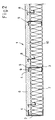
- eine Draufsicht auf den Rahmen des Verbund-Bodenelements nach einem ersten Ausführungsbeispiel der Erfindung mit in den Rahmen eingesetzten Querträgern,
Figur 2- einen Querschnitt durch das in Figur 1 gezeigte Verbund-Bodenelement gemäß der Erfindung.
Figur 3- einen Querschnitt durch ein Verbund-Bodenelement nach einer anderen Variante des ersten Ausführungsbeispiels der Erfindung,
- Figur 3a bis Figur 3g
- jeweils perspektivische Ansichten verschiedener Varianten von Querträgern nach dem ersten Ausführungsbeispiel der Erfindung (Vollverdübelung) und
Figur 4- einen Querschnitt durch ein Verbund-Bodenelement nach einem zweiten Ausführungsbeispiel der Erfindung (Endverdübelung).
- FIG. 1
- a plan view of the frame of the composite floor element according to a first embodiment of the invention with inserted into the frame cross members,
- FIG. 2
- a cross section through the composite floor element shown in Figure 1 according to the invention.
- FIG. 3
- a cross section through a composite floor element according to another variant of the first embodiment of the invention,
- FIG. 3a to FIG. 3g
- each perspective views of different variants of cross members according to the first embodiment of the invention (Vollverdübelung) and
- FIG. 4
- a cross section through a composite floor element according to a second embodiment of the invention (Endverdübelung).
Wie der Draufsicht in Figur 1 zu entnehmen ist, umfasst das Verbund-Bodenelement (1) gemäß der Erfindung einen Rahmen (2) und in diesem eingesetzte Querträger (3), die jeweils als U-Profile ausgebildet sein können, wobei die geöffnete Seite der U-Profile des Rahmens (2) nach innen weist und sich die Schenkel (4) des Rahmens (2) und der Querträger (3) in der Ebene des Verbund-Bodenelements (1) erstrecken. Die als Obergurte (5) der Profile dienenden Schenkel (4) sind in eine mit (6) bezeichnete Betonschicht eingebettet, welche auf eine Dämmstoffschicht (7) aus Mineralwolle als verlorene Schalung aufgebracht wurde. Die Dämmstoffschicht (7) ist zusätzlich mittels hakenförmigen Halteelementen (8) an der Betonschicht (6) verklammert, wobei die Halteelemente (8) ebenfalls einseitig in die Betonschicht (6) eingegossen sind.As can be seen from the plan view in FIG. 1, the composite floor element (1) according to the invention comprises a frame (2) and cross member (3) inserted therein, which can each be formed as U-profiles, the open side of the U-profile of the frame (2) facing inwards and the legs (4) of the frame (2) and the cross member (3) extend in the plane of the composite floor element (1). The legs (4) serving as upper girths (5) of the profiles are embedded in a concrete layer denoted by (6) which has been applied to a mineral wool insulating layer (7) as permanent formwork. The insulation layer (7) is additionally clamped by means of hook-shaped holding elements (8) on the concrete layer (6), wherein the holding elements (8) are also cast in one side in the concrete layer (6).
Wie dies nur aus der Ansicht in Figur 1 ersichtlich ist, sind die Obergurte (5) der Querträger (3) jeweils mit im Abstand von einander angeordneten Lochungen (9) versehen, die von dem Beton der Betonschicht (6) durchdrungen sind. Darüber hinaus sind die Profile der Querträger (3) von geringerer Stärke als die Profile des Rahmens (2).As can be seen only from the view in Figure 1, the upper straps (5) of the cross member (3) are each provided with spaced holes (9), which are penetrated by the concrete of the concrete layer (6). In addition, the profiles of the cross member (3) of lesser strength than the profiles of the frame (2).
Die Profile des Rahmens (2) sind in den Ecken miteinander verschweißt; die Querträger (3) sind ebenfalls in den Rahmen (2) eingeschweißt. Die Betonschicht (6) des Verbund-Bodenelements ist als Stahfaserbeton ausgebildet, d.h. in der Beton-Matrix sind Stahlnadeln (10) oder dergleichen dispers verteilt. Die Betonschicht muss nicht notwendigerweise in Stahlfaserbeton ausgeführt sein. Diese kann ohne Armierung oder alternativ oder zusätzlich mit einer Baustahlarmierung versehen sein.The profiles of the frame (2) are welded together in the corners; the cross members (3) are also welded into the frame (2). The concrete layer (6) of the composite floor element is designed as a steel fiber concrete, i. in the concrete matrix steel needles (10) or the like are dispersedly distributed. The concrete layer does not necessarily have to be made of steel fiber concrete. This can be provided without reinforcement or alternatively or additionally with a Baustahlarmierung.
Figur 3 zeigt eine weitere Variante des Verbund-Bodenelements (1) nach der Erfindung. Bei der in Figur 3 gezeigten Variante des Verbund-Bodenelements (1) sind die Querträger (3) als L-Profile (15) ausgebildet, wobei die L-Profile (15) einen kürzeren, sich in Einbaulage etwa horizontal erstreckenden Schenkel (16) und einen längeren, sich in Einbaulage etwa vertikal erstreckenden Abschnitt (17) aufweisen. Der sich vertikal erstreckende Abschnitt (17) der L-Profile (15) ist teilweise in die Betonschicht (6) eingebettet und teilweise von der Betonschicht (6) durchdrungen, wie dies nachstehend noch anhand der Figuren 3a - 3g erläutert werden wird. Des Weiteren können als zusätzliche Armierung Baustahlmatten (11) in die Betonschicht (6) eingebettet sein. Die Baustahlmatten (11) liegen auf Ausnehmungen, Abkantungen oder dergleichen der sich vertikal erstreckenden Schenkel (17) der L-Profile auf.FIG. 3 shows a further variant of the composite floor element (1) according to the invention. In the variant of the composite floor element (1) shown in FIG. 3, the cross members (3) are designed as L-profiles (15), wherein the L-profiles (15) have a shorter leg (16) extending approximately horizontally in the installed position. and a longer, approximately vertically in the installed position extending portion (17) exhibit. The vertically extending portion (17) of the L-profiles (15) is partially embedded in the concrete layer (6) and partially penetrated by the concrete layer (6), as will be explained below with reference to Figures 3a - 3g. Furthermore, reinforcing steel meshes (11) can be embedded in the concrete layer (6) as an additional reinforcement. The structural steel mats (11) rest on recesses, folds or the like of the vertically extending legs (17) of the L-profiles.
In Figur 3a ist perspektivisch eine Variante des Querträgers (3) dargestellt, bei welcher der in die Betonschicht (6) teilweise einzubettende Abschnitt (17) des L-Profils mit Abkantungen (18) versehen ist. Die Abkantungen (18) erstrecken sich wechselweise in verschiedene Richtungen. Bei der in Figur 3b dargestellten Variante des Querträgers (3) erstrecken sich die Abkantungen (18) nur in eine Richtung. Ebenso verhält es sich bei der in Figur 3c dargestellten Variante des Querträgers (3). Bei der in Figur 3d dargestellten Variante des Querträgers (3) ist dessen sich vertikal erstreckender Abschnitt (17) mit Schlitzen (19) versehen.FIG. 3 a shows a perspective view of a variant of the cross member (3), in which the section (17) of the L profile to be partially embedded in the concrete layer (6) is provided with folds (18). The folds (18) extend alternately in different directions. In the variant of the cross member (3) shown in Figure 3b, the bends (18) extend only in one direction. The same applies to the variant of the cross member (3) shown in Figure 3c. In the variant of the cross member (3) shown in Figure 3d whose vertically extending portion (17) is provided with slots (19).
Der in Figur 3e dargestellte Querträger (3) ist als U-Profil ausgebildet, wobei der Obergurt (5) des Querträgers (3) mit mehreren im Abstand voneinander angeordneten Winkelstücken (20) versehen ist. Eine weitere Variante des Querträgers (3) ist schließlich in Figur 3f gezeigt, wobei dort der sich in Einbaulage desselben vertikal erstreckende Schenkel (17) mit Lochungen (9) versehen ist.The cross member (3) shown in Figure 3e is formed as a U-profile, wherein the upper flange (5) of the cross member (3) with a plurality of spaced-apart angle pieces (20) is provided. A further variant of the crossbeam (3) is finally shown in FIG. 3f, where the leg (17) extending vertically in the installed position is provided with perforations (9).
Eine andere Variante des Verbund-Bodenelements gemäß der Erfindung ist in Figur 4 dargestellt. Bei dieser Ausführungsform ist der Rahmen (2) aus C-Profilen (12) zusammengesetzt. Die Querträger (3) sind als leichte Doppel-T-Profile (13) ausgebildet. Zusätzliche Maßnahmen zur Verankerung der Querträger (3) in der Betonschicht (6) sind bei dieser Ausführungsform des Verbund-Bodenelements (1) nicht vorgesehen.Another variant of the composite floor element according to the invention is shown in FIG. In this embodiment, the frame (2) is composed of C-profiles (12). The cross members (3) are designed as lightweight double T-profiles (13). Additional measures for anchoring the cross member (3) in the concrete layer (6) are not provided in this embodiment of the composite floor element (1).
Randseitig ist die Betonschicht (6) über Winkelprofile (14) eingefasst, die oberseitig auf die C-Profile (12) aufgeschweißt sind und über die die Kraftumleitung und Verbundwirkung erreicht wird.On the edge side, the concrete layer (6) is bordered by angle sections (14), which are welded on the top side to the C-profiles (12) and via which the force diversion and the bonding effect are achieved.
In Figur 3g ist schließlich eine Variante des Querträgers 3 gemäß der Erfindung dargestellt, der ebenfalls im Wesentlichen als L-Profil ausgebildet ist, dessen vertikale Schenkel sowohl mit Abkantungen (18) als auch mit Lochungen (9) von der Betonschicht durchdrungen werden. Diese Variante des L-Profils (15) hat sich als besonders günstig in Hinblick auf die zu erzielende Verbundwirkung erwiesen. Durch die Kombination aus Lochung (9) und Abkantung (18) wird eine permanente Verbundwirkung mit der Betonschicht (6) erzielt.Finally, FIG. 3g shows a variant of the
Von der Lochung kann auch zur Erhöhung der Verbundwirkung bei Bedarf ein Stabstahl aufgenommen werden. Durch den Stabstahl wird eine zusätzliche Verdübelung erzielt. Es ist für den Fachmann ersichtlich, dass die Lochung nur teilweise vom Stabstahl durchsetzt sein kann, beispielsweise kann jede zweite oder dritte Lochung (9) eines Querträgers (3) von einem Stabstahl durchsetzt sein. Die Abmessungen der Lochung (9) einerseits und des Stabstahls andererseits können so gewählt sein, dass die Lochung (9) zusätzlich von Beton durchsetzt wird.From the perforation can be added to increase the composite effect, if necessary, a steel bar. By the steel bar an additional anchoring is achieved. It will be apparent to those skilled in the art that the perforation may be only partially penetrated by the bar steel, for example, every second or third perforation (9) of a cross member (3) may be penetrated by a steel bar. The dimensions of the perforation (9) on the one hand and the bar steel on the other hand can be chosen so that the perforation (9) is additionally penetrated by concrete.
Es ist für den Fachmann nachvollziehbar, dass die Abkantung (18) senkrecht zur Ebene des Verbund-Bodenelements (1) wirkende Kräfte aufnimmt und damit die Kantenpressung der Querträger (3) verringert, sodass dies insgesamt zur Vermeidung von Rissbildung im Beton beiträgt.It is comprehensible to the person skilled in the art that the fold (18) absorbs forces acting perpendicular to the plane of the composite floor element (1) and thus reduces the edge pressure of the transverse beams (3), so that this contributes overall to the prevention of cracking in the concrete.
- (1)(1)
- Verbund-BodenelementComposite floor element
- (2)(2)
- Rahmenframe
- (3)(3)
- Querträgercrossbeam
- (4)(4)
- Schenkelleg
- (5)(5)
- Obergurtetop chords
- (6)(6)
- Betonschichtconcrete layer
- (7)(7)
- Dämmstoffschichtinsulation layer
- (8)(8th)
- Halteelementeretaining elements
- (9)(9)
- Lochungenperforations
- (10)(10)
- Stahlnadelnsteel needles
- (11)(11)
- Baustahlmattenwelded wire mesh
- (12)(12)
- C-ProfileC-sections
- (13)(13)
- Doppel-T-ProfileDouble-T profiles
- (14)(14)
- Winkelprofileangle sections
- (15)(15)
- L-ProfileL profiles
- (16)(16)
- Horizontale Schenkel der L-ProfileHorizontal legs of the L-profiles
- (17)(17)
- Vertikaler Abschnitt der L-ProfileVertical section of the L-profiles
- (18)(18)
- Abkantungenbends
- (19)(19)
- Schlitzeslots
- (20)(20)
- Winkelstückeelbows
Claims (15)
Applications Claiming Priority (1)
| Application Number | Priority Date | Filing Date | Title |
|---|---|---|---|
| DE200510038996 DE102005038996A1 (en) | 2005-08-16 | 2005-08-16 | Composite floor element |
Publications (2)
| Publication Number | Publication Date |
|---|---|
| EP1754842A2 true EP1754842A2 (en) | 2007-02-21 |
| EP1754842A3 EP1754842A3 (en) | 2009-01-07 |
Family
ID=37389100
Family Applications (1)
| Application Number | Title | Priority Date | Filing Date |
|---|---|---|---|
| EP06016187A Withdrawn EP1754842A3 (en) | 2005-08-16 | 2006-08-03 | Composite floor element |
Country Status (2)
| Country | Link |
|---|---|
| EP (1) | EP1754842A3 (en) |
| DE (1) | DE102005038996A1 (en) |
Cited By (3)
| Publication number | Priority date | Publication date | Assignee | Title |
|---|---|---|---|---|
| CN105064577A (en) * | 2015-08-05 | 2015-11-18 | 北京建工华创科技发展股份有限公司 | Prefabricated concrete composite floor slab |
| GB2607112A (en) * | 2021-05-29 | 2022-11-30 | Brennan Enterprise Ltd | A lightweight composite structural construction panel |
| WO2022254190A1 (en) * | 2021-05-29 | 2022-12-08 | Brennan Enterprise Limited | A lightweight composite structural construction panel |
Citations (6)
| Publication number | Priority date | Publication date | Assignee | Title |
|---|---|---|---|---|
| AT301131B (en) * | 1970-10-30 | 1972-08-25 | Josef Weidinger | Roof and ceiling boards |
| US4602467A (en) * | 1984-07-02 | 1986-07-29 | Schilger Herbert K | Thin shell concrete wall panel |
| US4885884A (en) * | 1988-05-25 | 1989-12-12 | Schilger Herbert K | Building panel assembly |
| EP0615035A2 (en) * | 1993-03-12 | 1994-09-14 | P & M MANUFACTURING CO., LTD. | Composite modular building panel |
| WO1999010607A2 (en) * | 1997-08-22 | 1999-03-04 | Dennis Leblang | Self-contained molded pre-fabricated building panel and method of making the same |
| JPH1171846A (en) * | 1997-08-28 | 1999-03-16 | Natl House Ind Co Ltd | Floor panel |
-
2005
- 2005-08-16 DE DE200510038996 patent/DE102005038996A1/en not_active Withdrawn
-
2006
- 2006-08-03 EP EP06016187A patent/EP1754842A3/en not_active Withdrawn
Patent Citations (6)
| Publication number | Priority date | Publication date | Assignee | Title |
|---|---|---|---|---|
| AT301131B (en) * | 1970-10-30 | 1972-08-25 | Josef Weidinger | Roof and ceiling boards |
| US4602467A (en) * | 1984-07-02 | 1986-07-29 | Schilger Herbert K | Thin shell concrete wall panel |
| US4885884A (en) * | 1988-05-25 | 1989-12-12 | Schilger Herbert K | Building panel assembly |
| EP0615035A2 (en) * | 1993-03-12 | 1994-09-14 | P & M MANUFACTURING CO., LTD. | Composite modular building panel |
| WO1999010607A2 (en) * | 1997-08-22 | 1999-03-04 | Dennis Leblang | Self-contained molded pre-fabricated building panel and method of making the same |
| JPH1171846A (en) * | 1997-08-28 | 1999-03-16 | Natl House Ind Co Ltd | Floor panel |
Cited By (3)
| Publication number | Priority date | Publication date | Assignee | Title |
|---|---|---|---|---|
| CN105064577A (en) * | 2015-08-05 | 2015-11-18 | 北京建工华创科技发展股份有限公司 | Prefabricated concrete composite floor slab |
| GB2607112A (en) * | 2021-05-29 | 2022-11-30 | Brennan Enterprise Ltd | A lightweight composite structural construction panel |
| WO2022254190A1 (en) * | 2021-05-29 | 2022-12-08 | Brennan Enterprise Limited | A lightweight composite structural construction panel |
Also Published As
| Publication number | Publication date |
|---|---|
| EP1754842A3 (en) | 2009-01-07 |
| DE102005038996A1 (en) | 2007-02-22 |
Similar Documents
| Publication | Publication Date | Title |
|---|---|---|
| DE60314459T2 (en) | CONSTRUCTION ELEMENT FOR CABINET CONSTRUCTION | |
| DE3408556C2 (en) | ||
| EP1669505B1 (en) | Steel-concrete composite joist with fire-resistant support for ceiling elements | |
| EP0163923A1 (en) | Connection between a cast-in-situ slab and precast columns | |
| EP1754842A2 (en) | Composite floor element | |
| AT407411B (en) | REINFORCEMENT BODY FOR A ROCK Ceiling made of cast concrete | |
| DE19721165B4 (en) | Industrially prefabricated lightweight ceiling or roof panels | |
| EP2405070A2 (en) | Steel beam for prefabricated floors | |
| DE4000956C2 (en) | Element for large panel construction made of concrete | |
| EP0811731B1 (en) | Ceiling construction and element | |
| DE2943786C2 (en) | Prefabricated, assembly-resistant panel element for the production of ceilings and method for its production | |
| DE2153495A1 (en) | PREFABRICATED CEILING PANEL FOR ASSEMBLY CONSTRUCTION | |
| DE202020100059U1 (en) | Formwork element | |
| WO2006128207A1 (en) | Constructional component in particular ground floor or cellar for commercial or domestic buildings | |
| EP3064672B1 (en) | Ceiling system in dry construction with a sandwich structure | |
| DE1916904A1 (en) | Composite ceiling | |
| DE3522382A1 (en) | Steel reinforcement for structural parts | |
| EP1227198A2 (en) | Composite steel floor | |
| EP3754125B1 (en) | Construction element for installation in expansion joints of buildings | |
| DE19630448A1 (en) | Connecting support for concrete reinforcement rods | |
| EP3315678A1 (en) | Prefabricated element for connecting a concrete cantilever plate to a building structure | |
| EP1312722B1 (en) | Construction element for a ceiling construction and ceiling construction in a building | |
| AT412295B (en) | HOLLOW WALL - CONNECTING SUPPORT FOR FULL APPLICATION OF THERMAL INSULATION PANELS ON THE INSIDE LOST FORMWORK | |
| EP2022908B1 (en) | Bulkhead formwork | |
| AT270962B (en) | Prefabricated, large-format, thin-walled reinforced concrete panel element |
Legal Events
| Date | Code | Title | Description |
|---|---|---|---|
| PUAI | Public reference made under article 153(3) epc to a published international application that has entered the european phase |
Free format text: ORIGINAL CODE: 0009012 |
|
| AK | Designated contracting states |
Kind code of ref document: A2 Designated state(s): AT BE BG CH CY CZ DE DK EE ES FI FR GB GR HU IE IS IT LI LT LU LV MC NL PL PT RO SE SI SK TR |
|
| AX | Request for extension of the european patent |
Extension state: AL BA HR MK YU |
|
| PUAL | Search report despatched |
Free format text: ORIGINAL CODE: 0009013 |
|
| AK | Designated contracting states |
Kind code of ref document: A3 Designated state(s): AT BE BG CH CY CZ DE DK EE ES FI FR GB GR HU IE IS IT LI LT LU LV MC NL PL PT RO SE SI SK TR |
|
| AX | Request for extension of the european patent |
Extension state: AL BA HR MK RS |
|
| RIC1 | Information provided on ipc code assigned before grant |
Ipc: E04B 5/10 20060101ALI20081202BHEP Ipc: E04C 2/38 20060101ALI20081202BHEP Ipc: E04B 5/02 20060101AFI20061117BHEP |
|
| AKX | Designation fees paid | ||
| STAA | Information on the status of an ep patent application or granted ep patent |
Free format text: STATUS: THE APPLICATION IS DEEMED TO BE WITHDRAWN |
|
| 18D | Application deemed to be withdrawn |
Effective date: 20090708 |
|
| REG | Reference to a national code |
Ref country code: DE Ref legal event code: 8566 |