EP1760428A1 - Reference beam generator and system for generating guiding beams for marking trolleys - Google Patents
Reference beam generator and system for generating guiding beams for marking trolleys Download PDFInfo
- Publication number
- EP1760428A1 EP1760428A1 EP05108174A EP05108174A EP1760428A1 EP 1760428 A1 EP1760428 A1 EP 1760428A1 EP 05108174 A EP05108174 A EP 05108174A EP 05108174 A EP05108174 A EP 05108174A EP 1760428 A1 EP1760428 A1 EP 1760428A1
- Authority
- EP
- European Patent Office
- Prior art keywords
- beam generator
- marking
- reference beam
- carrier element
- generator
- Prior art date
- Legal status (The legal status is an assumption and is not a legal conclusion. Google has not performed a legal analysis and makes no representation as to the accuracy of the status listed.)
- Withdrawn
Links
Images


Classifications
-
- G—PHYSICS
- G01—MEASURING; TESTING
- G01C—MEASURING DISTANCES, LEVELS OR BEARINGS; SURVEYING; NAVIGATION; GYROSCOPIC INSTRUMENTS; PHOTOGRAMMETRY OR VIDEOGRAMMETRY
- G01C15/00—Surveying instruments or accessories not provided for in groups G01C1/00 - G01C13/00
- G01C15/002—Active optical surveying means
- G01C15/004—Reference lines, planes or sectors
-
- A—HUMAN NECESSITIES
- A63—SPORTS; GAMES; AMUSEMENTS
- A63C—SKATES; SKIS; ROLLER SKATES; DESIGN OR LAYOUT OF COURTS, RINKS OR THE LIKE
- A63C19/00—Design or layout of playing courts, rinks, bowling greens or areas for water-skiing; Covers therefor
- A63C19/06—Apparatus for setting-out or dividing courts
-
- Y—GENERAL TAGGING OF NEW TECHNOLOGICAL DEVELOPMENTS; GENERAL TAGGING OF CROSS-SECTIONAL TECHNOLOGIES SPANNING OVER SEVERAL SECTIONS OF THE IPC; TECHNICAL SUBJECTS COVERED BY FORMER USPC CROSS-REFERENCE ART COLLECTIONS [XRACs] AND DIGESTS
- Y10—TECHNICAL SUBJECTS COVERED BY FORMER USPC
- Y10S—TECHNICAL SUBJECTS COVERED BY FORMER USPC CROSS-REFERENCE ART COLLECTIONS [XRACs] AND DIGESTS
- Y10S33/00—Geometrical instruments
- Y10S33/21—Geometrical instruments with laser
Definitions
- the laser transmission unit comprises a laser and a beam expander for producing a laser fan, preferably also a further optical component - for example a pentaprism - for splitting the laser fan into two partial compartments and is designed such that it can be attached to a laser fan defined position can be fixed, for example on the basis of a tripod or a support plate.
- the fan-beam emitting laser is mounted on a right angle two-leg angle plate such that it emits the laser beam at a defined distance from a line to be marked, according to the structural conditions of the used marking car.
- the detector of the marking trolley is preferably designed as a linear or surface array of photodiodes, which array is advantageously arranged on the control unit transversely to the laser light plane spanned by the laser transmitting unit of the reference beam generator.
- the division can be done eg in transmission or reflection.
- a common beam source and for the subsequent division a pentaprism is used. With that you can For most rectangular playing fields two outlines are defined. In reality, however, deviations from this geometry can occur if, for example, the playing field has to be determined using the goalposts and the goals are not oriented exactly parallel.
- the emission angle of the two or more partial beams can be made adjustable, for example by means of an adjustable adjustment wedge.
- the electronics of the marking cart 2 controls it now or shows corresponding corrections for the user that the deviation between the guide beam LS and the receiver axis is kept within a predetermined deviation.
- the reference beam generator 1 has an L-shaped base plate 11 with two legs oriented at right angles to one another as a carrier element.
- the components of the reference beam generator 1 are adjustably mounted on this base plate 11 which can be fixed relative to the earth's surface, wherein the base plate 11 itself can be adjusted by leg-like positioning elements 14 for coarse adjustment of the carrier element with respect to the earth's surface.
- the base plate 11 is opposed positioned a corner point EP and then made by adjusting the components a fine adjustment.
- the radiation emitted as a guide beam LS has an asymmetrical beam cross-section 5, which is elliptically illustrated here by way of example.
- the beam cross section 5 can already be provided by a corresponding cross section of the emission of the source or be formed after the generation.
- static methods such as by a cylindrical lens as Strahlaufweiter, or dynamic or time-dependent approaches, such as by a movement of the source or its emission, can be used.
- the detection of the reflected radiation is carried out by an optical detection component, for detecting and providing the radiation reflected by the reference target 4, which is designed here for the use of the human eye as a telescope 12.
- the optical detection component may also be used as an electro-optical detector, e.g. as a CCD or CMOS camera, so that automatic alignment processes, e.g. with drive by motors, are possible. With a corresponding intensity of the source or short distances can be dispensed with the optical detection component or an alignment without their use.
- FIG 3 the figurative representation of an embodiment of a reference beam generator 6 according to the invention takes place with an L-shaped base plate 61 as a support element and a pivotable and displaceable jet unit 62 with source and beam guiding means.
- An illustrative figurative representation of the components of this reference beam generator 6 takes place in Figs. 4-7.
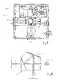
- FIG. 4 shows the base plate in a plan view.
- a slidable receptacle 63 is arranged for the jet unit, wherein this receptacle 63 also allows rotation of the jet unit.
- a first adjustment of the jet unit relative to the earth's surface can be done by moving the receptacle 63 on the base plate, wherein a quantization of the movement or position takes place by a division 64 on each of the two legs.
- FIG. 6 shows a view of the opened jet unit 62 with the components of source and beam guidance means, which are explained in greater detail in FIG. 7 in plan view.
- a pentaprism 69 is used in this example, which is fixed with a holder 69a and screws 69b in the jet unit.
- SQ electromagnetic radiation such as laser light is generated and coupled into the pentaprism 69.
- the angle of the two guide beams to each other, for example, by optical components be varied continuously or in discrete steps, for example by adjustable mirrors or optical wedges.
- FIG. 8 schematically illustrates the beam splitting by the pentaprism 69.
- the radiation of the laser diode 7 as a radiation source enters from the right side into the pentaprism 69 and strikes a semi-permeable surface 8, so that beam splitting takes place in the ratio of 50/50 and a part is coupled out as the first guide beam.
- the reflected portion strikes a mirror surface 9, e.g. on a silver mirror, and is finally emitted by an exit surface as a second guide beam.
- all the optical passage areas can be made to be low-reflection or transmission-increasing, e.g. through coatings.
- the angle adjustment between the two guide beams can be done, for example, by a wedge between pentaprism 69 and mirror surface 9, whereby the second guide beam is changed in its direction.
- a wedge between pentaprism 69 and mirror surface 9 whereby the second guide beam is changed in its direction.
- adjustable mirror surfaces or similar optical components for changing the emission direction.
Abstract
Description
Die Erfindung betrifft einen Referenzstrahlgenerator für zur Führung eines Markierwagens zur Erzeugung bodengebundener Markierungen nach dem Oberbegriff des Anspruchs 1 und ein System zur Erzeugung von Leitstrahlen für einen Markierwagen nach Anspruch 11.The invention relates to a reference beam generator for guiding a marking trolley for generating ground-based markings according to the preamble of
Zum Markieren von Sportfeldern ist es heute üblich, das Sportfeld genau auszumessen, abzustecken und mit einem Markierwagen abzufahren und zu markieren. Der Markierwagen weist einen Auslass für eine Markiersubstanz auf. In dieser Weise durchgeführte Markierungen sind ausgesprochen zeit-und auch kostenaufwendig, wenn sie von einer oder mehreren Arbeitspersonen durchgeführt werden. Die Arbeitspersonen müssen erst das gesamte - meist sehr grosse - Sportfeld abmessen und abstecken und dann das Feld mit dem Markierwagen abfahren. Die Positions-Genauigkeit der Markierung hängt dabei von der Führung des Wagens durch die Arbeitsperson ab. Zudem ergeben sich bei dieser Art von Markierarbeiten oft Abweichungen von den gewünschten Markierpositionen.To mark sports fields, it is customary today to measure the sports field exactly, stake out and start with a marking trolley and mark. The marking cart has an outlet for a marking substance. Markings made in this manner are extremely time-consuming and also costly when performed by one or more workers. The working people first have to measure and stake out the entire - usually very large - sports field and then drive off the field with the marking trolley. The position accuracy of the marker depends on the leadership of the car by the worker. In addition, deviations from the desired marking positions often result in this type of marking.
Eine Verbesserung der Markierarbeiten in Hinblick auf Genauigkeit, Zeitbedarf und Handhabungsfreundlichkeit bietet die Verwendung von optischen Leitstrahlen, die von einem Basissystem erzeugt werden und an durch die ein Markierwagen geführt werden kann.An improvement in marking accuracy, time and ease of use is provided by the use of optical beacons generated by a base system and to which a marking cart can pass.
Ein solches System wird beispielsweise in der
Die Ausbringung von Spielfeldmarkierungen mit solchen Systemen ist naturgemäss abhängig von der Handhabbarkeit und Genauigkeit des Leitstrahls. Dessen Positionierung und Lage im Raum kann sich dabei an verschiedenen Bezugsgrössen orientieren. Zumeist wird als ein Fixpunkt des zu markierenden Spielfeldes eine Ecke des Sportfeldes gewählt. Je nach Sportart, örtlichen Gegebenheiten und weiteren Umständen, wie z.B. Regelanforderungen, werden dann die Markierungen mit Bezug zu anderen Grössen definiert. Diese können beispielsweise bereits markierte Ecken eines Spielfeldes, Pfosten von Toren oder bereits vorhandene Grundlinien sein. Je nach Bedingungen können hierbei geringfügige Abweichungen von Idealmassen, z.B. durch schiefwinklige Spielfelder, entstehen.The application of field markings with such systems is of course dependent on the handling and accuracy of the beacon. Its positioning and position in space can be based on different reference quantities. In most cases, a corner of the sports field is chosen as a fixed point of the playing field to be marked. Depending on the sport, local conditions and other circumstances, such as Rule requirements, then the markers are defined with reference to other sizes. These can be, for example, already marked corners of a playing field, posts of goals or already existing baselines. Depending on the conditions, slight deviations from ideal masses, e.g. through oblique fields, arise.
Um eine entsprechend angepasste Markierung zu definieren, wird der emittierte Strahl zumeist bezüglich eines an einem Referenzpunkt positionierten Referenzzieles ausgerichtet.In order to define a correspondingly adapted marking, the emitted beam is mostly aligned with respect to a reference target positioned at a reference point.
Aufgabe der Erfindung ist es, ein System bzw. Systemkomponenten bereitzustellen, die eine vereinfachte und genauere Festlegung von Leitstrahlen für Markierwagen erlauben.The object of the invention is to provide a system or system components that allow a simplified and more accurate definition of guide beams for marking.
Eine weitere Aufgabe der Erfindung ist es, ein solches System bzw. Systemkomponenten mit grosser Reichweite, d.h. auch für grosse zu markierende Spielfelder bereitzustellen.A further object of the invention is to provide such a system or system components with a long range, i. also to be provided for large playing fields to be marked.
Diese Aufgaben werden erfindungsgemäss durch die Gegenstände der Ansprüche 1 und 11 bzw. der abhängigen Ansprüche gelöst oder die Lösungen weitergebildet.These objects are achieved according to the invention by the subject matters of
Die Erfindung stellt eine Lösung bereit, die ein schnelleres, vereinfachtes und genaueres Markieren von - insbesondere - Sportfeldern ermöglicht, indem das händische Abstecken eines Feldes durch ein "Abstecken" mittels einer Lasersendeeinheit ersetzt wird, indem die Sendeeinheit eine Ebene aufspannt, an welcher sich eine Markiereinrichtung orientieren kann.The invention provides a solution that allows faster, easier and more accurate marking of - in particular - sports fields by replacing the manual staking of a field by a "staking" by means of a laser transmitting unit by the transmitting unit spans a plane at which a Marking device can orient.
Dazu ist vorgesehen, die Lasersendeeinheit an einer geeigneten Ausgangsposition für ein Sportfeld zu positionieren - z.B. in der Ecke eines Fussballfeldes. Von der Sendeeinheit wird in wenigstens eine Richtung ein Laser-Fächerstrahl ausgesandt, vorzugsweise werden aber zwei zueinander rechtwinklige Fächerstrahlen ausgesandt. Diese Laser-Fächer spannen Ebenen senkrecht auf das zu markierendes Feld und als Referenz ("Absteckung") für zu markierende Linien auf. Durch so aufgespannte Fächer-Ebenen wird das Sportfeld - teilweise - definiert, sozusagen optisch - teilweise - abgesteckt.For this purpose, it is provided to position the laser transmission unit at a suitable starting position for a sports field - e.g. in the corner of a football field. From the transmitting unit, a laser fan beam is emitted in at least one direction, but preferably two fan-shaped fan beams are emitted. These laser trays span planes perpendicular to the field to be marked and as a reference ("stake out") for lines to be marked. The sports field is - partly - defined, so to speak optically - partly - staked out by so spanned subjects levels.
Die Lasersendeeinheit umfasst einen Laser und einen Strahlaufweiter zur Erzeugung eines Laserfächers, vorzugsweise auch eine weitere optische Komponente - z.B. ein Pentaprisma - zum Aufspalten des Laserfächers in zwei Teilfächer und ist so ausgebildet, dass sie an einer definierten Position fixierbar ist, beispielsweise anhand eines Stativs oder einer Trägerplatte. Im Allgemeinen wird der einen Fächerstrahl emittierende Laser auf einer rechtwinkligen Winkelplatte mit zwei Schenkeln montiert, und zwar derart, dass er den Laserstrahl in einem definierten Abstand zu einer zu markierenden Linie, entsprechend den baulichen Gegebenheiten des genutzten Markierwagens, emittiert. Der Detektor des Markierwagens ist vorzugsweise als Linear- oder Flächen-Array von Photodioden ausgebildet, welcher Array vorteilhaft auf der Steuereinheit quer zur durch die Lasersendeeinheit des Referenzstrahlgenerators aufgespannten Laserlicht-Ebene angeordnet ist.The laser transmission unit comprises a laser and a beam expander for producing a laser fan, preferably also a further optical component - for example a pentaprism - for splitting the laser fan into two partial compartments and is designed such that it can be attached to a laser fan defined position can be fixed, for example on the basis of a tripod or a support plate. In general, the fan-beam emitting laser is mounted on a right angle two-leg angle plate such that it emits the laser beam at a defined distance from a line to be marked, according to the structural conditions of the used marking car. The detector of the marking trolley is preferably designed as a linear or surface array of photodiodes, which array is advantageously arranged on the control unit transversely to the laser light plane spanned by the laser transmitting unit of the reference beam generator.
Mittels des photosensitiven Detektors werden die Lasersignale der Lasersendeinheit detektiert bzw. wird die (Ist-) Relativposition des Detektors bzw. des Markierwagens zur Laser-Ebene festgestellt. Wird dabei vom Detektor festgestellt, dass die Ist-Position von einer Soll-Position abweicht (d.h. z.B. dass der Detektor kein Signal oder ein Signal an der falschen Stelle empfängt), wird diese Information entsprechend verarbeitet. Dabei kann beispielsweise eine Anzeigeneinheit auf dem Markierwagen angebracht sein, die die Position des Detektors bzw. des Wagens gegenüber der Laserebene anzeigt, z.B. mittels unterschiedlicher Anzeigelampen. Insbesondere wird aber bei Feststellen einer Abweichung von der durch den Laser-Fächer aufgespannten Ebene eine Steueranweisung an die Ausbringungseinheit weitergegeben bzw. die Ausbringungseinheit der festgestellten Abweichung entsprechend gesteuert. Diese Steuerung kann auf unterschiedliche Art und Weise, z.B. auch vollautomatisch, erfolgen.By means of the photosensitive detector, the laser signals of the laser transmitting unit are detected or the (actual) relative position of the detector or of the marking carriage to the laser plane is detected. If the detector determines that the actual position deviates from a desired position (ie that the detector does not receive a signal or a signal in the wrong place), this information is processed accordingly. In this case, for example, a display unit may be mounted on the marking trolley, which indicates the position of the detector or the carriage relative to the laser plane, for example by means of different indicator lights. In particular, however, when a deviation from the plane defined by the laser fan is detected, a control instruction is forwarded to the application unit or the application unit is correspondingly controlled to determine the deviation. This control can be done in different ways, eg fully automatically.
Vorteilhafterweise ist der Referenzstrahlgenerator mit seiner Grundplatte - oder einem anderem Trägerelement als Halte- oder Positionierelement - so ausgebildet, dass er von einer Arbeitsperson getragen werden kann.Advantageously, the reference beam generator with its base plate - or another carrier element as a holding or positioning - is designed so that it can be carried by a worker.
Beim erfindungsgemässen Erzeugen bodengebundener Markierungen - z.B. für ein Sportfeld, ein Muster, eine Schrift, usw. - wird also folgendermassen vorgegangen: Eine Lasersendeeinheit wird - z.B. an einer Ecke des Feldes - positioniert. Zur räumlichen Festlegung des Leitstrahls für den Markierwagen wird die emittierte Strahlung auf ein Referenzziel gerichtet und so bezüglich des Referenzziels verstellt, dass eine definierte Ausrichtung, d.h. Position und Orientierung, auf dem Referenzziel erreicht wird. Falls bereits Elemente des zu bearbeitenden Feldes oder andere Bezugspunkte, wie z.B. Torpfosten auf einem Fussballfeld, vorhanden sind, kann über die Positionierung des Referenzziels eine Ausrichtung an diesen Objekten erfolgen. Die Sendeeinheit emittiert einen Laserstrahl, vorzugsweise einen fächerförmig aufgeweiteten Strahl, der eine Ebene festlegt, wobei diese Ebene anhand der Reflektion auf dem Referenzziel festgelegt wird.In the production of ground-based markings according to the invention - e.g. for a sports field, a pattern, a writing, etc. - the procedure is thus as follows: a laser transmitting unit is activated - e.g. at one corner of the field - positioned. In order to define the beacon for the marking car, the emitted radiation is directed to a reference target and adjusted with respect to the reference target such that a defined orientation, i. Position and orientation to reach the reference target. If already elements of the field to be processed or other reference points, e.g. Goal posts on a football field, alignment of these objects can be accomplished by positioning the reference target. The transmitting unit emits a laser beam, preferably a fan-shaped expanded beam, which defines a plane, this plane being determined on the basis of the reflection on the reference target.
Dabei werden der asymmetrische, insbesondere elliptische oder streifenförmige, Strahlquerschnitt und ein entsprechend ausgeformter reflektierender Bereich des Referenzziels zur Deckung gebracht. Erfindungsgemäss kann die Reflektion auf dem Referenzziel durch eine optische Komponente, wie z.B. ein Fernrohr bzw. Teleskop, betrachtet werden. Durch Verstellelemente wird die Ausrichtung der Emission solange verstellt, bis Strahlquerschnitt und reflektierender Bereich des Referenzziels zur Deckung gebracht worden sind. Durch die angepasste Gestaltung des reflektierenden Bereichs wird beim Erreichen der Überdeckung auch die maximale Intensität der Reflektion erreicht, so dass eine gute visuelle Erkennbarkeit folgt und auch eine Automatisierbarkeit möglich wird. Die Verstellung der Emissionsrichtung kann dabei mehrstufig erfolgen. Der gesamte Referenzstrahlgenerator kann zuerst mit seinem Trägerelement bezüglich der Erdoberfläche grob justiert, z.B. horizontiert, werden. Es kann aber auch als Emissionsausrichtung der von der Lasersendeeinheit ausgesandten Strahlung bzw. des Laserfächers eine nicht vertikale Orientierung zur Boden-Markierebene bzw. der Erdoberfläche oder eine nicht horizontierte Emission, z.B. bei ansteigendem, abfallendem oder welligem Gelände, gewählt werden. Eine feinere Verstellung kann dann über mechanische Feintriebe oder elektrische bzw. optische Komponenten bewirkt werden. Dabei kann der Verstellvorgang auch über Motoren unterstützt bzw. automatisiert werden.In this case, the asymmetrical, in particular elliptical or strip-shaped, beam cross-section and a correspondingly shaped reflective region of the reference target are made to coincide. According to the invention, the reflection on the reference target can be viewed through an optical component, such as a telescope or telescope. By adjustment, the orientation of the emission is adjusted as long as the beam cross-section and reflective area of the reference target to cover have been brought. Due to the adapted design of the reflective area, the maximum intensity of the reflection is achieved when the coverage is reached, so that a good visual recognition follows and an automatability is also possible. The adjustment of the emission direction can take place in several stages. The entire reference beam generator can first be coarsely adjusted with its carrier element with respect to the earth's surface, for example horizontally. However, it is also possible to choose as emission alignment of the radiation emitted by the laser emission unit or of the laser fan a non-vertical orientation to the ground marking plane or the earth's surface or a non-horizontal emission, for example in ascending, sloping or undulating terrain. A finer adjustment can then be effected via mechanical fine drives or electrical or optical components. The adjustment process can also be supported or automated via motors.
Störende Hintergrundstrahlung kann durch die Verwendung von Filtern, die nur für den emittierten Spektralbereich durchlässig sind, unterdrückt werden.Disturbing background radiation can be suppressed by the use of filters which are permeable only to the emitted spectral range.
Aufgrund der geometrischen Bedingungen der meisten Sportfelder ist eine gleichzeitige Erzeugung und Festlegung von zwei oder mehr Strahlen bzw. Teilstrahlen vorteilhaft, da so ohne Umstellen des Referenzstrahlgenerators zwei Leitstrahlen genutzt werden können. Erfindungsgemäss kann dies durch mehrere Strahlquellen oder eine Strahlteilung erfolgen, die Aufteilung kann dabei z.B. in Transmission oder Reflektion erfolgen. In einer erfindungsgemässe Ausführungsform wird eine gemeinsame Strahlquelle und zur nachfolgenden Teilung ein Pentaprisma genutzt. Damit können für die meisten rechtwinkligen Spielfelder zwei Aussenlinien definiert werden. In der Realität kann es jedoch zu Abweichungen von dieser Geometrie kommen, wenn z.B. das Spielfeld anhand der Torpfosten festgelegt werden muss und die Toren nicht exakt parallel orientiert sind. Um solche schiefwinkligen Spielfelder ebenfalls markieren zu können, kann der Emissionswinkel der zwei oder mehr Teilstrahlen einstellbar gestaltet werden, z.B. durch einen verstellbaren Justagekeil.Due to the geometric conditions of most sports fields, simultaneous generation and definition of two or more beams or partial beams is advantageous, since two guide beams can thus be used without switching the reference beam generator. According to the invention this can be done by multiple beam sources or beam splitting, the division can be done eg in transmission or reflection. In an embodiment according to the invention, a common beam source and for the subsequent division a pentaprism is used. With that you can For most rectangular playing fields two outlines are defined. In reality, however, deviations from this geometry can occur if, for example, the playing field has to be determined using the goalposts and the goals are not oriented exactly parallel. In order to also be able to mark such skewed playing fields, the emission angle of the two or more partial beams can be made adjustable, for example by means of an adjustable adjustment wedge.
An dem so durch Referenzstrahlgenerator und Referenzziel festgelegten Leitstrahl bzw. den mehreren Leitstrahlen kann sich ein Markierfahrzeug, welches z.B. von einer Arbeitsperson geschoben wird, orientieren. Die Orientierung des Geräts am Laserstrahl erfolgt über die Detektion des Leitstrahls auf einem Detektor des Geräts, vorzugsweise ein Photodioden- Zeilen- oder Flächenarray. Empfängt der Detektor ein falsches Signal, kann er z.B. die Information "zu weit links" bzw. "zu weit rechts" vermitteln, z.B. indem Alarmlampen aufleuchten. Weiters kann die Position des Auslasses des Markierfahrzeugs so lange korrigiert werden, bis der Detektor wieder das "richtige" Signal empfängt.At the guide beam or the plurality of guide beams thus defined by reference beam generator and reference target, a marking vehicle, which may be e.g. is pushed by a worker, orient. The orientation of the device on the laser beam via the detection of the beacon on a detector of the device, preferably a photodiode array or area array. If the detector receives a false signal, it can e.g. convey the information "too far to the left" or "too far to the right", e.g. by flashing alarm lamps. Furthermore, the position of the outlet of the marking vehicle can be corrected until the detector again receives the "correct" signal.
Ein erfindungsgemäßer Referenzstrahlengenerator und ein erfindungsgemässes System werden nachfolgend anhand von in der Zeichnung schematisch dargestellten Ausführungsbeispielen rein beispielhaft näher beschrieben. Im einzelnen zeigen
- Fig.1
- die schematische Erläuterung von Verfahren zur Markierung von Sportfeldern;
- Fig.2
- die schematische Darstellung des erfindungsgemässen Systems;
- Fig.3
- die figürliche Darstellung eines Ausführungsbeispiels für einen erfindungsgemässen Referenzstrahlgenerator;
- Fig.4-7
- die figürliche Darstellung von Komponenten des Ausführungsbeispiels für einen erfindungsgemässen Referenzstrahlgenerator und
- Fig.8
- die schematische Darstellung der Strahlaufteilung durch ein Pentaprisma für das Ausführungsbeispiel.
- Fig.1
- the schematic explanation of methods for marking sports fields;
- Fig.2
- the schematic representation of the inventive system;
- Figure 3
- the figurative representation of an embodiment of a reference beam generator according to the invention;
- Fig.4-7
- the figurative representation of components of the embodiment of a reference beam generator according to the invention and
- Figure 8
- the schematic representation of the beam split by a pentaprism for the embodiment.
Fig.1 erläutert ein beispielhaftes Verfahren zur Markierung von Sportfeldern nach dem Stand der Technik mit einer Steuerung eines Markierwagens 12 unter Verwendung eines Referenzstrahlengenerators 1'. Dargestellt wird eine Situation, bei der ein Spielfeld SP mit gattungsgemäßen Markierungen versehen werden soll. Dabei erfolgt die Vorgabe der zu markierenden Linie über einen von einem Bearbeiter zu bedienenden, auf einem Eckpunkt EP abgesetzt positionierten Referenzstrahlengenerator 1'. Der Markierwagen 2 wird über die Emission des Referenzstrahlgenerator 1' als Leitstrahl LS und optische Verbindung geführt. Zur Markierung einer Bearbeitungslinie, die eine Seite des Spielfeldes SP festlegt, muss der Markierwagen 2 mit seiner Empfänger zu einer Linie geführt werden, an der der Leitstrahl empfangen werden kann. Diese ist in diesem Beispiel nicht mit der Bearbeitungslinie deckungsgleich, da aufgrund des räumlichen Abstands zwischen Bearbeitungselementen und der Empfängerachse ein Versatz erforderlich ist, um die Markierung korrekt aufzubringen. Die Elektronik des Markierwagens 2 steuert diesen nun so bzw. zeigt entsprechende Korrekturen für den Nutzer an, dass die Abweichung zwischen Leitstrahl LS und Empfängerachse innerhalb einer vorgegebenen Abweichung gehalten wird. Durch die Festlegung des Leitstrahls LS kann somit der Markierwagen 2 mit der Empfängerachse auf einer Sollinie geführt werden, so dass eine Aufbringung der Markierung möglich ist.FIG. 1 illustrates an exemplary method of marking sports fields of the prior art with control of a marking
Sollen nun mehrere mit einem Winkel α zueinander gelegene Linien markiert werden, so muss bei Verfahren des Stands der Technik die Emission des Referenzstrahlgenerators 1' neu ausgerichtet werden, um einen weiteren Leitstrahl bereitzustellen. Durch sukzessive Neuausrichtung von Leitstrahlen LS kann schliesslich das gesamte Spielfeld SP markiert werden.If now several lines are to be marked with an angle .alpha., The emission of the reference beam generator 1 'must be realigned in the prior art method in order to provide a further guide beam. By successive reorientation of guiding beams LS, finally, the entire playing field SP can be marked.
Fig.2 zeigt die schematische Darstellung des erfindungsgemässen Systems mit dem Zusammenwirken seiner Komponenten. Von einem erfindungsgemässen Referenzstrahlgenerator 1 werden zwei Leitstrahlen LS unter einem vordefinierten Winkel, z.B. von 90°, in Richtung auf zwei Referenzziele 4 emittiert. Der Referenzstrahlengenerator 1 weist eine L-förmige Basisplatte 11 mit zwei rechtwinklig zueinander orientierten Schenkeln als Trägerelement auf. Auf dieser gegenüber der Erdoberfläche festlegbaren Basisplatte 11 sind die Komponenten des Referenzstrahlengenerators 1 verstellbar montiert, wobei die Basisplatte 11 selbst durch beinartige Positionierelemente 14 zur Grobjustierung des Trägerelements bezüglich der Erdoberfläche verstellt werden kann. In diesem Beispiel wird die Basisplatte 11 gegenüber einem Eckpunkt EP positioniert und dann durch Verstellung der Komponenten eine Feinjustierung vorgenommen. Auf der Basisplatte 11 ist eine Quelle elektromagnetischer Strahlung, z.B. eine Laserdiode, mit Strahlführungsmitteln 13 zur Emission der Strahlung verstellbar angeordnet. Die als Leitstrahl LS emittierte Strahlung weist dabei einen asymmetrischen, hier exemplarisch elliptisch dargestellten Strahlquerschnitt 5 auf. Der Strahlquerschnitt 5 kann dabei bereits durch einen entsprechenden Querschnitt der Emission der quelle bereitgestellt werden oder aber nach der Erzeugung geformt werden. Hierbei können statische Methoden, wie z.B. durch eine Zylinderlinse als Strahlaufweiter, oder dynamische bzw. zeitabhängige Ansätze, wie z.B. durch eine Bewegung der Quelle oder deren Emission, genutzt werden. So kann z.B. durch ein Scannerrad die Abtastung bzw. Emission in einen linearen, streifenförmigen Bereich bewirkt werden, so dass über die Zeit betrachtet eine fächerförmige Emission erfolgt. Durch eine solche Emission der beiden Leitstrahlen LS kann ein oder mehrere Markierwagen zur Erzeugung von zwei Linien 3a und 3b des Spielfeldes geführt werden, wobei die generierten Fächer der Leitstrahlen LS die Ebenen zur Orientierung und Ausrichtung der Markierwagen bereitstellen.2 shows the schematic representation of the inventive system with the interaction of its components. From a
Dem Strahlquerschnitt 5 entspricht der reflektierende Bereich 41 der Referenzziele 4 in seiner Form bzw. dem Querschnitt, so dass bei einem Übereinstimmen von Strahlquerschnitt 5 und reflektierendem Bereich 41 das Intensitätsmaximum der Reflektion die korrekte Ausrichtung anzeigt. Die Form des reflektierenden Bereichs 41 kann dabei durch die Form des reflektierenden Materials selbst, z.B. eines Streifens einer reflektierenden Folie, oder durch eine entsprechend geformte Abdeckung des reflektierenden Materials, z.B. durch eine Maske mit einem Schlitz, bewirkt werden. Dabei kann das Referenzziel 4 ebenfalls mit einem Referenzträgerelement in zum Referenzstrahlgenerator 1 bzw. dessen Basisplatte 11 ähnlicher Weise ausgebildet werden, z.B. mit zwei Schenkeln in L-Form und verstellbaren Beinen, so dass auch für das Referenzziel 4 entsprechende Verstellmöglichkeiten bestehen.The
Die Erfassung der reflektierten Strahlung erfolgt durch eine optische Erfassungskomponente, zur Erfassung und Bereitstellung der von dem Referenzziel 4 reflektierten Strahlung, die hier für die Nutzung des menschlichen Auges als Teleskop 12 ausgebildet ist. Alternativ oder ergänzend kann die optische Erfassungskomponente auch als elektrooptischer Detektor, z.B. als CCD- oder CMOS-Kamera, ausgebildet sein, so dass auch automatische Ausrichtprozesse, z.B. mit Antrieb durch Motoren, möglich sind. Bei einer entsprechenden Intensität der Quelle oder kurzen Entfernungen kann auch auf die optische Erfassungskomponente verzichtet werden bzw. eine Ausrichtung auch ohne deren Nutzung erfolgen.The detection of the reflected radiation is carried out by an optical detection component, for detecting and providing the radiation reflected by the
In Fig.3 erfolgt die figürliche Darstellung eines Ausführungsbeispiels für einen erfindungsgemässen Referenzstrahlgenerator 6 mit einer L-förmigen Basisplatte 61 als Trägerelement und einer schwenk- und verschiebbaren Strahleinheit 62 mit Quelle und Strahlführungsmitteln. Eine erläuternde figürliche Darstellung der Komponenten dieses Referenzstrahlgenerators 6 erfolgt in den Fig.4-7.In Figure 3, the figurative representation of an embodiment of a
Fig.4 zeigt die Basisplatte in einer Draufsicht. Auf der Basisplatte ist eine verschiebbare Aufnahme 63 für die Strahleinheit angeordnet, wobei diese Aufnahme 63 zudem eine Rotation der Strahleinheit ermöglicht. Eine erste Justierung der Strahleinheit gegenüber der Erdoberfläche kann durch Verschieben der Aufnahme 63 auf der Basisplatte erfolgen, wobei durch eine Einteilung 64 auf jedem der beiden Schenkel eine Quantifizierung der Bewegung bzw. Position erfolgt.4 shows the base plate in a plan view. On the base plate, a
Die Basisplatte 61 selbst wird vorab bezüglich eines ausgezeichneten Punktes auf der Erdoberfläche positioniert und festgelegt. Eine entsprechende Verstellbarkeit in Höhe und Neigung wird durch drei höhenverstellbare Füsse bzw. beinartige Komponenten 65 bewirkt. Diese weisen auf ihrer Unterseite tellerartige Platten 66 und zumindest bei zwei der beinartigen Komponenten 65 auf der Oberseite eine Verstelltrieb 67 auf. Mit der Basisplatte 61 sind die beinartigen Komponenten 65 durch Durchführungen und Buchsen 68 verbunden.The
Fig.6 zeigt eine Ansicht der geöffneten Strahleinheit 62 mit den Komponenten von Quelle und Strahlführungsmitteln, welche in Fig.7 in Draufsicht näher erläutert werden. Zur Strahlteilung wird in diesem Beispiel ein Pentaprisma 69 verwendet, das mit einer Halterung 69a und Schrauben 69b in der Strahleinheit fixiert ist. Durch die auf der rechten Seite angeordnete Strahlquelle SQ wird elektromagnetische Strahlung, z.B. Laserlicht generiert und in das Pentaprisma 69 eingekoppelt. Dort erfolgt eine Aufteilung und nachfolgende über zugeordnete Optiken eine Emission als Leitstrahlen LS. Der Winkel der beiden Leitstrahlen zueinander kann beispielsweise durch optische Komponenten kontinuierlich oder in diskreten Schritten variiert werden, z.B. durch verstellbare Spiegel oder optische Keile.FIG. 6 shows a view of the opened
Hierbei erläutert Fig.8 die Strahlaufteilung durch das Pentaprisma 69 schematisch. Die Strahlung der Laserdiode 7 als Strahlungsquelle tritt von der rechten Seite her in das Pentaprisma 69 ein und trifft auf eine halbdurchlässige Fläche 8, so dass Strahlaufteilung im Verhältnis von 50/50 erfolgt und ein Teil als erster Leitstrahl ausgekoppelt wird. Der reflektierte Anteil trifft auf eine Spiegelfläche 9, z.B. auf einen Silberspiegel, und wird schliesslich durch eine Austrittsfläche als zweiter Leitstrahl emittiert. Zusätzlich können alle optischen Durchtrittsflächen reflexmindern bzw. transmissionserhöhend ausgebildet sein, z.B. durch Beschichtungen. Die Winkeleinstellung zwischen beiden Leitstrahlen kann beispielsweise durch einen keil zwischen Pentaprisma 69 und Spiegelfläche 9 erfolgen, wodurch der zweiten Leitstrahl in seiner Richtung verändert wird. Alternativ oder ergänzend können jedoch auch verstellbare Spiegelflächen oder ähnliche optische Komponenten zur Veränderung der Emissionsrichtung verwendet werden.FIG. 8 schematically illustrates the beam splitting by the
Claims (13)
gekennzeichnet durch
eine optische Erfassungskomponente, insbesondere ein Teleskop (12), zur Erfassung und Bereitstellung der von dem Referenzziel (4) reflektierten Strahlung, insbesondere für das menschliche Auge.
marked by
an optical detection component, in particular a telescope (12), for detecting and providing the radiation reflected by the reference target (4), in particular for the human eye.
dadurch gekennzeichnet, dass
durch die Strahlführungsmitteln die Ausrichtung des Strahlquerschnitts (5) gegenüber der Erdoberfläche einstellbar ist, insbesondere mit gegenüber der Erdoberfläche vertikaler Ausrichtung eines elliptischen Strahlquerschnitts (5).Reference beam generator (1,6) according to claim 1,
characterized in that
the orientation of the beam cross-section (5) relative to the earth's surface is adjustable by the beam guiding means, in particular with respect to the earth's surface vertical alignment of an elliptical beam cross-section (5).
gekennzeichnet durch
einen Strahlaufweiter zur Erzeugung eines in einer Richtung statisch oder dynamisch aufgeweiteten Strahlquerschnitts (5).Reference beam generator (1,6) according to claim 1 or 2,
marked by
a beam expander for generating a statically or dynamically expanded beam cross-section (5) in one direction.
dadurch gekennzeichnet, dass
die optische Erfassungskomponente einen für die emittierte optische Strahlung durchlässigen optischen Filter aufweist.Reference beam generator (1,6) according to one of the preceding claims,
characterized in that
the optical detection component comprises an optical filter transmissive to the emitted optical radiation.
dadurch gekennzeichnet, dass
die Strahlführungsmittel einen Strahlteiler zur Erzeugung von wenigstens zwei Teilstrahlen, insbesondere ein Pentaprisma (69), aufweisen.Reference beam generator (1,6) according to one of the preceding claims,
characterized in that
the beam guiding means comprise a beam splitter for producing at least two partial beams, in particular a pentaprism (69).
dadurch gekennzeichnet, dass
der Strahlteiler einen einstellbaren Emissionswinkel der wenigstens zwei Teilstrahlen aufweist, insbesondere durch einen optischen Keil.Reference beam generator (1,6) according to claim 5,
characterized in that
the beam splitter has an adjustable emission angle of the at least two partial beams, in particular by an optical wedge.
gekennzeichnet durch
einen Feintrieb zur Verstellung der Ausrichtung der Emission, insbesondere mit einer elektrooptischen Erfassungskomponente und einem Motor zur automatisierten Verstellung.Reference beam generator (1,6) according to one of the preceding claims,
marked by
a fine drive for adjusting the orientation of the emission, in particular with an electro-optical detection component and a motor for automated adjustment.
gekennzeichnet durch
wenigstens ein, insbesondere drei, Positionierelemente (14,65) zur Grobjustierung des Trägerelements (11,61) bezüglich der Erdoberfläche.Reference beam generator (1,6) according to one of the preceding claims,
marked by
at least one, in particular three, positioning elements (14, 65) for coarse adjustment of the carrier element (11, 61) with respect to the earth's surface.
dadurch gekennzeichnet, dass
das Trägerelement (11,61) eine Geometrie mit zwei rechtwinklig angeordneten Schenkeln, insbesondere eine L-förmige Geometrie, aufweist.Reference beam generator (1,6) according to one of the preceding claims,
characterized in that
the carrier element (11, 61) has a geometry with two legs arranged at right angles, in particular an L-shaped geometry.
dadurch gekennzeichnet, dass
Komponenten der Strahlführungsmittel bezüglich der Schenkel längsverschiebbar angeordnet sind.Reference beam generator (1,6) according to claim 9,
characterized in that
Components of the beam guiding means with respect to the legs are arranged longitudinally displaceable.
dadurch gekennzeichnet, dass
der reflektierende Bereich (41) als linienförmiger Reflektor oder als Maske mit einem Schlitz vor einem Reflektor ausgebildet ist.System according to claim 11,
characterized in that
the reflective region (41) is designed as a linear reflector or as a mask with a slot in front of a reflector.
dadurch gekennzeichnet, dass
das Referenzziel (4) ein gegenüber der Erdoberfläche definiert positionierbares, insbesondere veranker- und horizontierbares, Referenzträgerelement aufweist, wobei der reflektierende Bereich (41) gegenüber dem Referenzträgerelement verstellbar ausgebildet ist.System according to claim 11 or 12,
characterized in that
the reference target (4) has a relative to the earth's surface positionable, in particular anchored and horizontalable, reference carrier element, wherein the reflective region (41) relative to the reference carrier element is adjustable.
Priority Applications (3)
| Application Number | Priority Date | Filing Date | Title |
|---|---|---|---|
| EP05108174A EP1760428A1 (en) | 2005-09-06 | 2005-09-06 | Reference beam generator and system for generating guiding beams for marking trolleys |
| US11/277,221 US7434322B2 (en) | 2005-09-06 | 2006-03-22 | Reference beam generator and system for producing guide beams for field markers |
| AU2006201178A AU2006201178B2 (en) | 2005-09-06 | 2006-03-22 | Reference beam generator and system for producing guide beams for field markers |
Applications Claiming Priority (1)
| Application Number | Priority Date | Filing Date | Title |
|---|---|---|---|
| EP05108174A EP1760428A1 (en) | 2005-09-06 | 2005-09-06 | Reference beam generator and system for generating guiding beams for marking trolleys |
Publications (1)
| Publication Number | Publication Date |
|---|---|
| EP1760428A1 true EP1760428A1 (en) | 2007-03-07 |
Family
ID=35734054
Family Applications (1)
| Application Number | Title | Priority Date | Filing Date |
|---|---|---|---|
| EP05108174A Withdrawn EP1760428A1 (en) | 2005-09-06 | 2005-09-06 | Reference beam generator and system for generating guiding beams for marking trolleys |
Country Status (3)
| Country | Link |
|---|---|
| US (1) | US7434322B2 (en) |
| EP (1) | EP1760428A1 (en) |
| AU (1) | AU2006201178B2 (en) |
Cited By (3)
| Publication number | Priority date | Publication date | Assignee | Title |
|---|---|---|---|---|
| DE102012005512A1 (en) | 2012-03-19 | 2013-09-19 | Jan Bernd Lüschen | Method and device for the design of soil and green areas |
| DE102012022870A1 (en) | 2012-11-22 | 2014-05-22 | Thomas Baur | Automated marking wagon for automated marking of boundaries and lines in athletic playground field, has control unit that controls pump and spray nozzle based on camera data, and controls continuation of markings at junctions |
| US9528818B2 (en) | 2007-05-04 | 2016-12-27 | Beamrider Limited | Control method for producing ground markings, and reference beam generator |
Families Citing this family (22)
| Publication number | Priority date | Publication date | Assignee | Title |
|---|---|---|---|---|
| EP1703300A1 (en) * | 2005-03-17 | 2006-09-20 | Leica Geosystems AG | Method and system for determining position and orientation of an object |
| EP1855174A1 (en) * | 2006-05-11 | 2007-11-14 | Leica Geosystems AG | Laser level generator for generation of guiding beams for marking vehicles |
| AT504565B1 (en) * | 2006-11-24 | 2008-09-15 | Sola Messwerkzeuge Gmbh | CROSS-LASER DEVICE FOR LAYING UP PANEL OR BOARD FLOOR ELEMENTS |
| US7889322B2 (en) * | 2007-02-20 | 2011-02-15 | Electro Scientific Industries, Inc. | Specimen inspection stage implemented with processing stage coupling mechanism |
| US7603785B2 (en) * | 2007-02-20 | 2009-10-20 | Electro Scientific Industries, Inc. | Air bearing assembly for guiding motion of optical components of a laser processing system |
| US7886449B2 (en) * | 2007-02-20 | 2011-02-15 | Electro Scientific Industries, Inc. | Flexure guide bearing for short stroke stage |
| US20090019712A1 (en) * | 2007-07-17 | 2009-01-22 | Sinclair Abt, Llc | Apparatus and Method of Displaying Designs for a Building |
| US8006394B2 (en) * | 2007-09-05 | 2011-08-30 | Musco Corporation | Apparatus, method and system of precise identification of multiple points distributed throughout an area |
| US7984557B1 (en) * | 2009-06-05 | 2011-07-26 | Carl Keith D | Laser-guided positioning device |
| US8405485B2 (en) * | 2009-10-21 | 2013-03-26 | Musco Corporation | Apparatus, method, and system for identification of multiple points located throughout an area |
| US8713808B2 (en) * | 2009-11-30 | 2014-05-06 | Alan Amron | System and method for projecting a visible line on an athletic field surface |
| US9587491B2 (en) | 2010-09-22 | 2017-03-07 | Joy Mm Delaware, Inc. | Guidance system for a mining machine |
| CA2813008C (en) * | 2010-09-22 | 2019-01-15 | Joy Mm Delaware, Inc. | Guidance system for a mining machine |
| FR2965912B1 (en) * | 2010-10-07 | 2013-04-26 | Rieux Des | METROLOGY DEVICE FOR TRACING REFERENCE LINES ON THE INTERNAL WALL OF A ROTARY FURNACE |
| US8925211B2 (en) * | 2011-01-14 | 2015-01-06 | Donald P. DuFour | Laser-based alignment device and associated methods thereof |
| US8302319B1 (en) | 2011-06-13 | 2012-11-06 | International Business Machines Corporation | Method and apparatus for aligning and leveling a server rack rail |
| US9127935B2 (en) * | 2012-01-04 | 2015-09-08 | Chris Olexa | Laser centering tool for surface areas |
| US8826553B2 (en) * | 2012-04-20 | 2014-09-09 | Trimble Navigation Limited | Layout equipment and layout method |
| US9677880B2 (en) * | 2015-05-01 | 2017-06-13 | United Technologies Corporation | Laser alignment system |
| US10048069B2 (en) | 2015-07-17 | 2018-08-14 | Raul Romero | Utility locating tool |
| US9656154B1 (en) * | 2015-08-13 | 2017-05-23 | Martin Rodriguez | Sports field marking system |
| US10466051B2 (en) * | 2017-01-03 | 2019-11-05 | Lee Edward Haynes | Sporting field measurement system |
Citations (5)
| Publication number | Priority date | Publication date | Assignee | Title |
|---|---|---|---|---|
| US4090708A (en) * | 1976-10-26 | 1978-05-23 | Mcpeak Walter G | Apparatus for marking football fields |
| DE4013950A1 (en) | 1990-04-30 | 1991-11-07 | Fraunhofer Ges Forschung | Laser-guided straight line marking appts. - adjusts travel direction of paint-dispensing vehicle relative to laser beam |
| EP1061335A2 (en) * | 1999-06-15 | 2000-12-20 | Kabushiki Kaisha Topcon | Position detecting apparatus |
| US6202312B1 (en) | 1999-03-08 | 2001-03-20 | Levelite Technology, Inc. | Laser tool for generating perpendicular lines of light on floor |
| WO2006013386A2 (en) | 2004-08-06 | 2006-02-09 | Fleet (Line Markers) Limited | Line marking apparatus |
Family Cites Families (19)
| Publication number | Priority date | Publication date | Assignee | Title |
|---|---|---|---|---|
| US2755555A (en) * | 1953-04-13 | 1956-07-24 | William T Spaeder | Leveling target |
| US3588255A (en) * | 1968-03-12 | 1971-06-28 | Technidyne Inc | Optical alignment methods and means utilizing coordinated laser beams and laser beam coordinating means for same |
| US3936197A (en) * | 1974-05-06 | 1976-02-03 | Laser Alignment, Inc. | Self-leveling laser assembly |
| SE420353B (en) * | 1980-04-23 | 1981-09-28 | Pharos Ab | DEVICE FOR CHECKING MATERIAL |
| US4681439A (en) * | 1985-10-28 | 1987-07-21 | Shoemaker Jack W | Pipe laying method and apparatus |
| US4908948A (en) * | 1988-06-30 | 1990-03-20 | Gormley Brendan J | Precision optical square instrument |
| US5118184A (en) * | 1990-11-20 | 1992-06-02 | Kordana Zigmond J | Transit for establishing 90 degree angles |
| US5218770A (en) * | 1990-11-27 | 1993-06-15 | Asahi Seimitsu Kabushiki Kaisha | Surveying machine for construction work |
| US5243398A (en) * | 1991-02-15 | 1993-09-07 | Laser Alignment, Inc. | Surveying instrument including low power light plane generator |
| US5402226A (en) * | 1993-05-17 | 1995-03-28 | Matthews; Jeffrey M. | Survey apparatus |
| US5541727A (en) * | 1993-08-27 | 1996-07-30 | Rando; Joseph F. | Automatic level and plumb tool |
| JP3599805B2 (en) * | 1994-12-09 | 2004-12-08 | 株式会社トプコン | Surveying instrument |
| US5864956A (en) * | 1996-11-22 | 1999-02-02 | Dong; Dawei | Level line and limb line combination |
| US5748306A (en) * | 1997-02-12 | 1998-05-05 | Louis; Daniel P. | Visual alignment instrument |
| DE19733491B4 (en) * | 1997-08-01 | 2009-04-16 | Trimble Jena Gmbh | Goal finding method for geodetic devices |
| US6002473A (en) * | 1997-12-24 | 1999-12-14 | Dove-Tec, Inc. | Optical level and square |
| EP1329690A1 (en) * | 2002-01-22 | 2003-07-23 | Leica Geosystems AG | Method and device for automatic locating of targets |
| US6694629B2 (en) * | 2002-02-27 | 2004-02-24 | Trimble Navigation Llc | Laser projector for producing intersecting lines on a surface |
| US7178250B2 (en) * | 2004-07-21 | 2007-02-20 | Irwin Industrial Tool Company | Intersecting laser line generating device |
-
2005
- 2005-09-06 EP EP05108174A patent/EP1760428A1/en not_active Withdrawn
-
2006
- 2006-03-22 AU AU2006201178A patent/AU2006201178B2/en not_active Ceased
- 2006-03-22 US US11/277,221 patent/US7434322B2/en not_active Expired - Fee Related
Patent Citations (5)
| Publication number | Priority date | Publication date | Assignee | Title |
|---|---|---|---|---|
| US4090708A (en) * | 1976-10-26 | 1978-05-23 | Mcpeak Walter G | Apparatus for marking football fields |
| DE4013950A1 (en) | 1990-04-30 | 1991-11-07 | Fraunhofer Ges Forschung | Laser-guided straight line marking appts. - adjusts travel direction of paint-dispensing vehicle relative to laser beam |
| US6202312B1 (en) | 1999-03-08 | 2001-03-20 | Levelite Technology, Inc. | Laser tool for generating perpendicular lines of light on floor |
| EP1061335A2 (en) * | 1999-06-15 | 2000-12-20 | Kabushiki Kaisha Topcon | Position detecting apparatus |
| WO2006013386A2 (en) | 2004-08-06 | 2006-02-09 | Fleet (Line Markers) Limited | Line marking apparatus |
Cited By (5)
| Publication number | Priority date | Publication date | Assignee | Title |
|---|---|---|---|---|
| US9528818B2 (en) | 2007-05-04 | 2016-12-27 | Beamrider Limited | Control method for producing ground markings, and reference beam generator |
| DE102012005512A1 (en) | 2012-03-19 | 2013-09-19 | Jan Bernd Lüschen | Method and device for the design of soil and green areas |
| DE102012005512B4 (en) * | 2012-03-19 | 2014-07-31 | Jan Bernd Lüschen | Device for the design of soil and green areas |
| US9161491B2 (en) | 2012-03-19 | 2015-10-20 | Jan Lüschen | Method and apparatus for styling grounds and lawns |
| DE102012022870A1 (en) | 2012-11-22 | 2014-05-22 | Thomas Baur | Automated marking wagon for automated marking of boundaries and lines in athletic playground field, has control unit that controls pump and spray nozzle based on camera data, and controls continuation of markings at junctions |
Also Published As
| Publication number | Publication date |
|---|---|
| US7434322B2 (en) | 2008-10-14 |
| US20070062053A1 (en) | 2007-03-22 |
| AU2006201178A1 (en) | 2007-03-29 |
| AU2006201178B2 (en) | 2011-08-11 |
Similar Documents
| Publication | Publication Date | Title |
|---|---|---|
| EP1760428A1 (en) | Reference beam generator and system for generating guiding beams for marking trolleys | |
| DE2926168C2 (en) | Device for measuring the circumference of an object | |
| DE19707590C2 (en) | Method and device for adjusting the alignment of a beam characteristic of a distance sensor | |
| EP3045998B1 (en) | Marking vehicle and method | |
| DE2802107C2 (en) | ||
| EP2145154B1 (en) | Operating method for creating ground markings and reference beam generator | |
| DE2409563A1 (en) | METHOD AND DEVICE FOR GUIDANCE | |
| EP2016473B1 (en) | Reference beam generator for generating guide beams for marking machines | |
| DE2809090A1 (en) | DEVICE AND METHOD FOR MEASURING THE WHEEL ALIGNMENT OF MOTOR VEHICLES | |
| DE19524475C1 (en) | Optical centring unit for positioning SMD semiconductor element, or a laser diode, on substrate | |
| WO2011098608A1 (en) | Marking device and system for surveying land | |
| DE2202172C3 (en) | Arrangement for automatic tracking | |
| DE3518036A1 (en) | DEVICE FOR HOLDING AN INSTRUMENT ALIGNED WITH A MOVING REFLECTOR | |
| DE10224147A1 (en) | Geodetic device with multiple beam paths | |
| DE102017010055A1 (en) | Laser beam welding of geometric figures with OCT seam guide | |
| DE102008010407B4 (en) | Method and device for projecting an optical projection on a projection surface | |
| DE3431616C2 (en) | ||
| EP0429691B1 (en) | Device for determining the position of a target from a predetermined position | |
| DE3145823C2 (en) | Device for determining points | |
| DE4222659C2 (en) | Scanning obstacle warning device | |
| DE2215960A1 (en) | Device for tracking a luminous target | |
| DE102005016718B4 (en) | Method for adjusting object sensors of a motor vehicle | |
| EP3438525B1 (en) | Lighting device for simulation apparatus for motor vehicle accidents | |
| EP0264591A2 (en) | Method for measuring the optical axes of a projector guide beam and device for carrying out the method | |
| DE3803566A1 (en) | X-ray diagnostic system for making stereotactic brain diagnoses |
Legal Events
| Date | Code | Title | Description |
|---|---|---|---|
| PUAI | Public reference made under article 153(3) epc to a published international application that has entered the european phase |
Free format text: ORIGINAL CODE: 0009012 |
|
| AK | Designated contracting states |
Kind code of ref document: A1 Designated state(s): AT BE BG CH CY CZ DE DK EE ES FI FR GB GR HU IE IS IT LI LT LU LV MC NL PL PT RO SE SI SK TR |
|
| AX | Request for extension of the european patent |
Extension state: AL BA HR MK YU |
|
| 17P | Request for examination filed |
Effective date: 20070825 |
|
| AKX | Designation fees paid |
Designated state(s): AT BE BG CH CY CZ DE DK EE ES FI FR GB GR HU IE IS IT LI LT LU LV MC NL PL PT RO SE SI SK TR |
|
| 17Q | First examination report despatched |
Effective date: 20100722 |
|
| RAP1 | Party data changed (applicant data changed or rights of an application transferred) |
Owner name: BEAMRIDER LTD |
|
| GRAP | Despatch of communication of intention to grant a patent |
Free format text: ORIGINAL CODE: EPIDOSNIGR1 |
|
| INTG | Intention to grant announced |
Effective date: 20171114 |
|
| GRAJ | Information related to disapproval of communication of intention to grant by the applicant or resumption of examination proceedings by the epo deleted |
Free format text: ORIGINAL CODE: EPIDOSDIGR1 |
|
| GRAP | Despatch of communication of intention to grant a patent |
Free format text: ORIGINAL CODE: EPIDOSNIGR1 |
|
| INTC | Intention to grant announced (deleted) | ||
| INTG | Intention to grant announced |
Effective date: 20180416 |
|
| GRAJ | Information related to disapproval of communication of intention to grant by the applicant or resumption of examination proceedings by the epo deleted |
Free format text: ORIGINAL CODE: EPIDOSDIGR1 |
|
| INTC | Intention to grant announced (deleted) | ||
| STAA | Information on the status of an ep patent application or granted ep patent |
Free format text: STATUS: THE APPLICATION IS DEEMED TO BE WITHDRAWN |
|
| 18D | Application deemed to be withdrawn |
Effective date: 20190402 |