EP1764582A2 - Apparatus and method for detecting steps in a personal navigation system - Google Patents
Apparatus and method for detecting steps in a personal navigation system Download PDFInfo
- Publication number
- EP1764582A2 EP1764582A2 EP06120837A EP06120837A EP1764582A2 EP 1764582 A2 EP1764582 A2 EP 1764582A2 EP 06120837 A EP06120837 A EP 06120837A EP 06120837 A EP06120837 A EP 06120837A EP 1764582 A2 EP1764582 A2 EP 1764582A2
- Authority
- EP
- European Patent Office
- Prior art keywords
- user
- zero crossing
- sliding window
- acceleration
- personal navigation
- Prior art date
- Legal status (The legal status is an assumption and is not a legal conclusion. Google has not performed a legal analysis and makes no representation as to the accuracy of the status listed.)
- Granted
Links
Images

Classifications
-
- G—PHYSICS
- G01—MEASURING; TESTING
- G01C—MEASURING DISTANCES, LEVELS OR BEARINGS; SURVEYING; NAVIGATION; GYROSCOPIC INSTRUMENTS; PHOTOGRAMMETRY OR VIDEOGRAMMETRY
- G01C21/00—Navigation; Navigational instruments not provided for in groups G01C1/00 - G01C19/00
- G01C21/10—Navigation; Navigational instruments not provided for in groups G01C1/00 - G01C19/00 by using measurements of speed or acceleration
-
- G—PHYSICS
- G01—MEASURING; TESTING
- G01C—MEASURING DISTANCES, LEVELS OR BEARINGS; SURVEYING; NAVIGATION; GYROSCOPIC INSTRUMENTS; PHOTOGRAMMETRY OR VIDEOGRAMMETRY
- G01C22/00—Measuring distance traversed on the ground by vehicles, persons, animals or other moving solid bodies, e.g. using odometers, using pedometers
- G01C22/006—Pedometers
-
- H—ELECTRICITY
- H04—ELECTRIC COMMUNICATION TECHNIQUE
- H04B—TRANSMISSION
- H04B1/00—Details of transmission systems, not covered by a single one of groups H04B3/00 - H04B13/00; Details of transmission systems not characterised by the medium used for transmission
- H04B1/38—Transceivers, i.e. devices in which transmitter and receiver form a structural unit and in which at least one part is used for functions of transmitting and receiving
- H04B1/40—Circuits
Definitions
- the present invention relates to a personal navigation system, and more particularly, to an apparatus and a method for detecting steps in a personal navigation system.
- Personal navigation systems are typically used for route guidance and position determination. Accordingly, personal navigation systems provide users with route information by detecting a user's present position.
- Personal navigation systems are typically included in portable terminals such as portable phones, personal digital assistants (PDAs), portable GPS receivers, and the like. These personal navigation systems typically include a Global positioning system (GPS) receiver, an accelerometer, and a geomagnetic sensor. Some personal navigation systems can determine a user's stride based on GPS information and generate a navigation solution according to the assumed stride so as to provide a navigation service. Thus, precise step information is necessary in order to provide a precise navigation service. That is, stride detection is a very important factor in the personal navigation system.
- GPS Global positioning system
- An accelerometer held by or attached to a user can be used for step detection.
- steps correspond to a users steps and will hereinafter be referred to as “steps” or “step” unless context indicates otherwise.
- the accelerometer counts steps based on acceleration variation according to impacts generated when people walk or run. Accordingly, the acceleration variation must be precisely measured for the purpose of precise step detection.
- the acceleration variation is directly measured based on an acceleration signal generated from an acceleration sensor, precision of the step detection will be degraded if the acceleration variation is not distinct. Accordingly, it is preferred to detect the steps when variation of the acceleration signal generated from the acceleration sensor is distinct and can be easily distinguished as will be explained below.
- the acceleration sensor is attached to an item of clothing worn by a user and/or to the user's shoe, waist, or leg which generally experience great impact when the user walks or runs, thereby obtaining distinct acceleration variation for step detection.
- a sensor module must be located separately from a personal navigation terminal and a communication module must be provided for the purpose of data communication between the sensor module and the personal navigation terminal which can increase hardware complexity of the personal navigation system.
- the sensor module may internally communicate with the personal navigation terminal. Accordingly, a separate communication module a user interface for interfacing the sensor module and the personal navigation terminal are not necessary. However, problems may occur because acceleration is measured in the hand-held state.
- a shoulder or an elbow may serve as a damper, so that impact, corresponding to a user's foot making contact with the ground, may not be precisely transferred to the acceleration sensor.
- acceleration variation corresponding to a user's stride cannot be accurately measured, causing an error in step detection. Therefore, it is necessary to provide a technique capable of accurately measuring variation of an acceleration signal generated from an acceleration sensor.
- the present invention has been made to solve the above-mentioned problems occurring in the prior art.
- the object of the present invention is to provide an apparatus and a method for precisely detecting steps in a personal navigation system by processing an acceleration signal output from an acceleration sensor such that variation of the acceleration signal can be distinctly obtained.
- An aspect of the present invention is to provide an apparatus and a method for precisely detecting steps in a personal navigation system by processing an acceleration signal output from an acceleration sensor installed in a hand-held type personal navigation terminal such that variation of the acceleration signal can be distinctly obtained.
- an apparatus for step detection in a personal navigation system includes an acceleration sensor for detecting acceleration in a movement direction and a gravity direction relative to a user and then outputting acceleration signals according to the detection result; and a moving distance measurement device for calculating sliding window summing data for the acceleration signals output from the acceleration sensor in the movement direction and the gravity direction so as to calculate a sum of the sliding window summing data, and then detecting steps of the user by using differential sliding window summing data.
- a method for step detection in a personal navigation system including obtaining acceleration signals from an acceleration sensor in a movement direction and a gravity direction relative to a user; calculating sliding window summing data corresponding to the acceleration signals of the acceleration sensor in the movement direction and the gravity direction; calculating a sum of the sliding window summing data, and differential sliding window summing data; and detecting steps of the user based on the differential sliding window summing data.
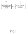
- FIG. 1 is a block diagram illustrating the structure of a step detection apparatus in a personal navigation system according to the present invention.
- the step detection apparatus includes an acceleration sensor 110 and a moving distance measurement device 120.
- the acceleration sensor 110 may include an MEMS (micro electro mechanical system) sensor, that is, a micro sensor which can be installed in a personal navigation terminal, such as a portable phone or a PDA.
- the acceleration sensor 110 can detect acceleration in at least two axial directions and outputs a corresponding acceleration signal.
- the acceleration sensor 110 may be implemented in the form of a tri-axial accelerometer or may include three single-axial accelerometers.
- the acceleration sensor 110 is installed in the personal navigation terminal in such a manner that an X-axis is positioned along a lateral side (left or right direction) of a user, a Y-axis is positioned in a movement direction of the user, and a Z-axis is positioned in a gravity direction.
- the acceleration component of a step i.e., acceleration in the y axis in the present example
- the movement direction i.e., movement in the y axis in the present example
- the acceleration sensor 110 installed in the personal navigation terminal detects a linear movement in the X, Y and Z-axis directions and then outputs an acceleration signal according to the detection result.
- the moving distance measurement device 120 may include a controller such as an 8-bit micro-controller (for example, an Atmega128 available from Atmel company).
- the moving distance measurement device 120 detects the step by using the acceleration signal output from the acceleration sensor 110.
- the moving distance measurement device 120 detects the step by adding the acceleration signal in the Y-axis direction to the acceleration signal in the Z-axis direction, because the acceleration signals in the Y and Z-axis directions can reflect a user's walking pattern. Since the phase of the acceleration signal in the Y-axis direction is similar to that of the acceleration signal in the Z-axis direction, when the above acceleration signals are added to each other, signal phases are overlapped with each other, so that substantial signal attenuation does not occur. Rather the signal value of each phase increases representing a distinct walking signal pattern
- the acceleration signal output from the acceleration sensor 110 may include various errors in addition to noise.
- noise, bias and errors such as a conversion coefficient error or a misalignment error, may become serious.
- the above parameters exert an influence upon the walk pattern, thereby disturbing the step detection.
- the moving distance measurement device 120 performs a sliding window summing relative to the acceleration signals generated from the acceleration sensor 110 in X, Y, and Z-axis directions, thereby smoothing the acceleration signals in each axial direction while removing noise contained in the acceleration signals.
- the moving distance measurement device 120 calculates the sum of sliding window summing data for the acceleration signals generated in the Y and Z-axis directions, thereby obtaining a distinct walking signal pattern.
- bias and various errors such as the conversion coefficient error or the misalignment error, are not easily removed.
- the bias and various error components may be presented even if the sliding window summing data are added to each other.
- the moving distance measurement device 120 differentiates the sum of the sliding window summing data for the acceleration signals of the Y and Z-axis directions so as to remove the bias and errors presented in the sum of the sliding window summing data.
- the differential sliding window summing data may have acceleration signal components only, without the noise, bias and errors. Accordingly, the sliding window summing data may be sufficiently processed for representing the walk pattern.
- the moving distance measurement device 120 detects a step by analyzing the pattern of the sliding window summing data. That is, the moving distance measurement device 120 detects a time when a signal of the sliding window summing data passes through a zero point by using a zero crossing method and then detects the step based on zero crossing detection.
- the zero crossing detection can also be obtained by means of chattering (e.g., vibration) of a human body in addition to the step of the user.
- chattering e.g., vibration
- the zero crossing detection is derived from the step of the user or chattering of the human body.
- vibration may be applied to the hand-held type personal navigation terminal through a hand or an arm of the user. Accordingly, in the case of the hand-held type personal navigation terminal having the acceleration sensor 110 therein, it is necessary to determine whether the zero crossing detection is derived from the step of the user or chattering of the human body.
- the moving distance measurement device 120 calculates a difference of a detection time between present zero crossing detection and previous zero crossing detection and compares the difference value with a threshold value, thereby detecting the step.
- the threshold value can be obtained through experimentation.
- the acceleration signals output from the acceleration sensor 110 are processed so as to obtain a distinct signal pattern for walk and then the step is detected based on the distinct signal pattern, so that the step of the user can be precisely detected.
- the step detection apparatus according to the present invention can distinguish zero crossing detection caused by chattering of the human body from zero crossing detection caused by the step of the user, so the step detection apparatus can more precisely detect the step of the user.
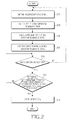
- FIG. 2 is a flowchart illustrating the procedure of step detection in the personal navigation system according to the present invention.
- the moving distance measurement apparatus 120 detects the acceleration signal generated from the acceleration sensor 110 in X, Y, and Z-axis directions (step 202).
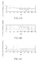
- the acceleration signals as shown in FIGs. 3A to 3C are generated from the acceleration sensor 110.
- FIG. 3A is a graph illustrating a waveform of an acceleration signal generated in the X-axis direction (the lateral direction of the user)
- FIG. 3B is a graph illustrating a waveform of an acceleration signal generated in the Y-axis direction (the movement direction of the user)
- FIG. 3C is a graph illustrating a waveform of an acceleration signal generated in the Z-axis direction (the gravity direction).
- a longitudinal axis represents acceleration and a transverse axis represents time.
- variation of the acceleration signal waveform according to walking is negligible.
- walking variation of the acceleration signal waveform is greater than that of the acceleration signal waveform shown in FIG. 3A. Accordingly, it can be understood that the walk pattern of the user is greatly reflected in the acceleration signals of the Y and Z-axis directions.
- the moving distance measurement device 120 preferably uses the acceleration signals of the Y and Z-axis directions representing greater variation of the waveforms.
- the moving distance measurement device 120 calculates sliding window summing data relative to the acceleration signals by using a sliding window summing scheme (step 204).
- the sliding window summing scheme refers to a signal processing scheme for adding acceleration values of a window period to each other while sliding a window relative to a time axis.
- the sliding window summing data for acceleration signals can be calculated according to Equation 1.
- Equation 1 t is time, N is a window size, a(k) is an acceleration signal value as a function of time (t), and SWS(t) is a value of sliding window summing.
- FIGs. 4A to 4C are graphs illustrating sliding window summing data relative to acceleration signals of X, Y, and Z-axis directions according to the present invention.
- the calculation results of the sliding window summing data are obtained by applying the acceleration signals of the acceleration sensor 110 to Equation 1.
- FIG. 4A is a graph illustrating the calculation result of the sliding window summing data obtained by applying the sliding window scheme to the waveform of the acceleration signal in the X-axis direction.
- FIG. 4B is a graph illustrating the calculation result of the sliding window summing data obtained by applying the sliding window scheme to the waveform of the acceleration signal in the Y-axis direction.
- FIG. 4C is a graph illustrating the calculation result of the sliding window summing data obtained by applying the sliding window summing scheme to the waveform of the acceleration signal in the Z-axis direction.
- a longitudinal axis represents sliding window summing and a transverse axis represents time.
- the moving distance measurement device 120 calculates the sum of sliding window summing data for the acceleration signals generated in the Y and Z-axis directions (step 206).
- the moving distance measurement device 120 differentiates the sliding window summing data for the acceleration signals generated in the Y and Z-axis directions according to Equation 2 (step 208).
- Equation 2 ⁇ SWS ( t ) is the differential sliding window summing data, SWS 0 ( t ) is the sliding window summing data for acceleration signals in which errors have been removed, and SWS ⁇ ( t ) is the sliding window summing data for error components contained in acceleration signals.
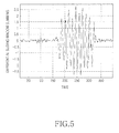
- differential sliding window summing data obtained according to Equation 2 is shown in FIG. 5.
- a longitudinal axis represents differential sliding window summing data and a transverse axis represents time.
- the waveform of the differential sliding window summing data represents an acceleration signal component in which noise, bias and errors have been removed, so that the distinct signal pattern for walk can be obtained. Accordingly, the above differential sliding window summing data signifies that the acceleration signals are sufficiently processed to represent the distinct signal pattern corresponding to a user's walk.
- the moving distance measurement device 120 detects a zero crossing point on the basis of the differential sliding window summing data by using the walk pattern in order to detect the step of the user (step 210). That is, the moving distance measurement device 120 detects a time when a signal of the sliding window summing data passes through the zero point by using the zero crossing method, thereby detecting the zero crossing point. As mentioned above, the zero crossing may occur caused by the step of the user or chattering of the human body.
- the moving distance measurement device 120 compares a difference value of a detection time between present zero crossing detection and previous zero crossing detection with a threshold value (step 212).
- the threshold value can be obtained through experimentation. According to the present invention, the threshold value is about 15 samples (0.3 second) based on a data rate of (50 Hz). If the difference value of the detection time between present zero crossing detection and previous zero crossing detection is equal to or less than the threshold value, the moving distance measurement device 120 determines that the zero crossing detection occurs caused by chattering of the human body, so the procedure returns to step 210. However, if the difference value of the detection time between present zero crossing detection and previous zero crossing detection is greater than the threshold value, the moving distance measurement device 120 determines that the zero crossing detection occurs caused by the step of the user (step 214).
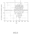
- FIG. 6 is a graph illustrating the step detection result according to the present invention.
- "a" is a waveform of differential sliding window summing data
- "b" is a point where the zero crossing detection occurs. It can be precisely detected that the user walks 10-steps by counting the point where the zero crossing detection occurs.
- the present invention has been described that the sum of the sliding window summing data for acceleration signals in the Y and Z-axis directions is calculated after the sliding window summing data for acceleration signals in the X, Y and Z-axis directions have been calculated, it is also possible to calculate the sum of the acceleration signals in the Y and Z-axis directions before the sliding window summing data have been calculated. In this case, the sliding window summing scheme is applied to the sum of the acceleration signals.
- the acceleration signals generated from the acceleration sensor are processed such that the distinct walking signal pattern can be obtained, thereby precisely detecting the step of the user based on the distinct signal pattern.
- the step detection apparatus can distinguish zero crossing detection caused by chattering of the human body from zero crossing detection caused by the step of the user, so the step detection apparatus can more precisely detect the step of the user.
- a hand-held type personal navigation system including a micro sensor module and a portable phone or a PDA.
Abstract
Description
- The present invention relates to a personal navigation system, and more particularly, to an apparatus and a method for detecting steps in a personal navigation system.
- Personal navigation systems are typically used for route guidance and position determination. Accordingly, personal navigation systems provide users with route information by detecting a user's present position.
- Personal navigation systems are typically included in portable terminals such as portable phones, personal digital assistants (PDAs), portable GPS receivers, and the like. These personal navigation systems typically include a Global positioning system (GPS) receiver, an accelerometer, and a geomagnetic sensor. Some personal navigation systems can determine a user's stride based on GPS information and generate a navigation solution according to the assumed stride so as to provide a navigation service. Thus, precise step information is necessary in order to provide a precise navigation service. That is, stride detection is a very important factor in the personal navigation system.
- An accelerometer held by or attached to a user can be used for step detection. As used herein, these "steps" correspond to a users steps and will hereinafter be referred to as "steps" or "step" unless context indicates otherwise. The accelerometer counts steps based on acceleration variation according to impacts generated when people walk or run. Accordingly, the acceleration variation must be precisely measured for the purpose of precise step detection.
- However, if the acceleration variation is directly measured based on an acceleration signal generated from an acceleration sensor, precision of the step detection will be degraded if the acceleration variation is not distinct. Accordingly, it is preferred to detect the steps when variation of the acceleration signal generated from the acceleration sensor is distinct and can be easily distinguished as will be explained below.
- Conventionally, the acceleration sensor is attached to an item of clothing worn by a user and/or to the user's shoe, waist, or leg which generally experience great impact when the user walks or runs, thereby obtaining distinct acceleration variation for step detection. However, in this case, a sensor module must be located separately from a personal navigation terminal and a communication module must be provided for the purpose of data communication between the sensor module and the personal navigation terminal which can increase hardware complexity of the personal navigation system.
- Although a method for detecting steps in a hand-held state in which an acceleration sensor is installed in the personal navigation terminal this method typically attempts to detect a user's step in a state in which a user holds the personal navigation terminal in his or her hand.
- If the acceleration sensor is installed in the personal navigation terminal, the sensor module may internally communicate with the personal navigation terminal. Accordingly, a separate communication module a user interface for interfacing the sensor module and the personal navigation terminal are not necessary. However, problems may occur because acceleration is measured in the hand-held state.
- That is, if the acceleration is measured in the hand-held state, a shoulder or an elbow may serve as a damper, so that impact, corresponding to a user's foot making contact with the ground, may not be precisely transferred to the acceleration sensor. In this case, acceleration variation corresponding to a user's stride cannot be accurately measured, causing an error in step detection. Therefore, it is necessary to provide a technique capable of accurately measuring variation of an acceleration signal generated from an acceleration sensor.
- Accordingly, the present invention has been made to solve the above-mentioned problems occurring in the prior art.
- The object of the present invention is to provide an apparatus and a method for precisely detecting steps in a personal navigation system by processing an acceleration signal output from an acceleration sensor such that variation of the acceleration signal can be distinctly obtained.
- This object is solved by the subject matter of the independent claims.
- Preferred embodiments are defined in the dependent claims.
- An aspect of the present invention is to provide an apparatus and a method for precisely detecting steps in a personal navigation system by processing an acceleration signal output from an acceleration sensor installed in a hand-held type personal navigation terminal such that variation of the acceleration signal can be distinctly obtained.
- In order to accomplish the above, according to one aspect of the present invention, there is provided an apparatus for step detection in a personal navigation system, the apparatus includes an acceleration sensor for detecting acceleration in a movement direction and a gravity direction relative to a user and then outputting acceleration signals according to the detection result; and a moving distance measurement device for calculating sliding window summing data for the acceleration signals output from the acceleration sensor in the movement direction and the gravity direction so as to calculate a sum of the sliding window summing data, and then detecting steps of the user by using differential sliding window summing data.
- According to another aspect of the present invention, there is provided a method for step detection in a personal navigation system, the method including obtaining acceleration signals from an acceleration sensor in a movement direction and a gravity direction relative to a user; calculating sliding window summing data corresponding to the acceleration signals of the acceleration sensor in the movement direction and the gravity direction; calculating a sum of the sliding window summing data, and differential sliding window summing data; and detecting steps of the user based on the differential sliding window summing data.
- The present invention will be more apparent from the following detailed description taken in conjunction with the accompanying drawings, in which:
- FIG. 1 is a block diagram illustrating the structure of a step detection apparatus in a personal navigation system according to an embodiment of the present invention;
- FIG. 2 is a flowchart illustrating the procedure of step detection in a personal navigation system according to the present invention;
- FIGs. 3A to 3C are graphs illustrating waveforms of acceleration signals generated from an acceleration sensor in X, Y, and Z-axis directions according to the present invention;
- FIGs. 4A to 4C are graphs illustrating sliding window summing data relative to acceleration signals of X, Y and Z-axis directions according to the present invention;
- FIG. 5 is a graph illustrating differential sliding window summing data according to the present invention; and
- FIG. 6 is a graph illustrating a step detection result according to the present invention.
- Hereinafter, preferred embodiments of the present invention will be described with reference to the accompanying drawings. Wherever possible, the same reference numbers will be used throughout the drawings to refer to the same or like parts. In addition, a detailed description of known functions and configurations incorporated herein will be omitted when it may make the subject matter of the present invention unclear. The terms used in the following description are defined by taking functions thereof into consideration, so the terms may vary depending on customs or intentions of a user/administrator. Thus, definitions of the terms used in this application should be construed in accordance with, and in conjunction with, the teachings of the present application.
- FIG. 1 is a block diagram illustrating the structure of a step detection apparatus in a personal navigation system according to the present invention. Referring to FIG. 1, the step detection apparatus includes an
acceleration sensor 110 and a movingdistance measurement device 120. - The
acceleration sensor 110 may include an MEMS (micro electro mechanical system) sensor, that is, a micro sensor which can be installed in a personal navigation terminal, such as a portable phone or a PDA. Theacceleration sensor 110 can detect acceleration in at least two axial directions and outputs a corresponding acceleration signal. According to the present invention, theacceleration sensor 110 may be implemented in the form of a tri-axial accelerometer or may include three single-axial accelerometers. On the assumption that the body of the personal navigation terminal is parallel to the ground in use, theacceleration sensor 110 is installed in the personal navigation terminal in such a manner that an X-axis is positioned along a lateral side (left or right direction) of a user, a Y-axis is positioned in a movement direction of the user, and a Z-axis is positioned in a gravity direction. At this time, although precise alignment of each axis is preferred in order to be consistent with the corresponding direction of the axis, since the acceleration component of a step (i.e., acceleration in the y axis in the present example) is more important than the movement direction (i.e., movement in the y axis in the present example) of the step in the present invention, the above axes can be slightly tilted in a predetermined range provided that the tilt does not exert a substantial influence upon acceleration signal detection. In addition, as mentioned above, theacceleration sensor 110 installed in the personal navigation terminal detects a linear movement in the X, Y and Z-axis directions and then outputs an acceleration signal according to the detection result. - The moving
distance measurement device 120 may include a controller such as an 8-bit micro-controller (for example, an Atmega128 available from Atmel company). The movingdistance measurement device 120 detects the step by using the acceleration signal output from theacceleration sensor 110. In particular, the movingdistance measurement device 120 detects the step by adding the acceleration signal in the Y-axis direction to the acceleration signal in the Z-axis direction, because the acceleration signals in the Y and Z-axis directions can reflect a user's walking pattern. Since the phase of the acceleration signal in the Y-axis direction is similar to that of the acceleration signal in the Z-axis direction, when the above acceleration signals are added to each other, signal phases are overlapped with each other, so that substantial signal attenuation does not occur. Rather the signal value of each phase increases representing a distinct walking signal pattern - However, the acceleration signal output from the
acceleration sensor 110 may include various errors in addition to noise. In particular, since each axis of theacceleration sensor 110 may be shaken when theacceleration sensor 110 is installed in the hand-held type personal navigation terminal, noise, bias and errors, such as a conversion coefficient error or a misalignment error, may become serious. The above parameters (noise, bias, conversion coefficient error, misalignment error, etc.) exert an influence upon the walk pattern, thereby disturbing the step detection. - Thus, the moving
distance measurement device 120 according to the present invention performs a sliding window summing relative to the acceleration signals generated from theacceleration sensor 110 in X, Y, and Z-axis directions, thereby smoothing the acceleration signals in each axial direction while removing noise contained in the acceleration signals. - In addition, the moving
distance measurement device 120 calculates the sum of sliding window summing data for the acceleration signals generated in the Y and Z-axis directions, thereby obtaining a distinct walking signal pattern. - However, although noise can be removed from the acceleration signal through the sliding window summing scheme, bias and various errors, such as the conversion coefficient error or the misalignment error, are not easily removed. Thus, the bias and various error components may be presented even if the sliding window summing data are added to each other.
- For this reason, the moving
distance measurement device 120 differentiates the sum of the sliding window summing data for the acceleration signals of the Y and Z-axis directions so as to remove the bias and errors presented in the sum of the sliding window summing data. As a result, the differential sliding window summing data may have acceleration signal components only, without the noise, bias and errors. Accordingly, the sliding window summing data may be sufficiently processed for representing the walk pattern. - Thus, the moving
distance measurement device 120 detects a step by analyzing the pattern of the sliding window summing data. That is, the movingdistance measurement device 120 detects a time when a signal of the sliding window summing data passes through a zero point by using a zero crossing method and then detects the step based on zero crossing detection. - However, the zero crossing detection can also be obtained by means of chattering (e.g., vibration) of a human body in addition to the step of the user. Thus, when it is detected that the signal of the sliding window summing data passes through the zero point, it must be determine whether the zero crossing detection is derived from the step of the user or chattering of the human body. In particular, since the user usually walks while holding the hand-held type personal navigation terminal having the
acceleration sensor 110 therein, vibration may be applied to the hand-held type personal navigation terminal through a hand or an arm of the user. Accordingly, in the case of the hand-held type personal navigation terminal having theacceleration sensor 110 therein, it is necessary to determine whether the zero crossing detection is derived from the step of the user or chattering of the human body. - However, since the user walks with a predetermined stride, the zero crossing detection caused by the step of the user is presented with a predetermined interval. In contrast, the zero crossing detection caused by the chattering of the human body is presented several times with a relatively short interval because the chattering of the human body refers to vibration of the human body. Thus, it is possible to determine whether the zero crossing detection is derived from the step of the user or chattering of the human body based on the interval of the zero crossing detection. Therefore, the moving
distance measurement device 120 according to the present invention calculates a difference of a detection time between present zero crossing detection and previous zero crossing detection and compares the difference value with a threshold value, thereby detecting the step. The threshold value can be obtained through experimentation. - According to the step detection apparatus having the above structure, the acceleration signals output from the
acceleration sensor 110 are processed so as to obtain a distinct signal pattern for walk and then the step is detected based on the distinct signal pattern, so that the step of the user can be precisely detected. In addition, the step detection apparatus according to the present invention can distinguish zero crossing detection caused by chattering of the human body from zero crossing detection caused by the step of the user, so the step detection apparatus can more precisely detect the step of the user. - Hereinafter, the method for step detection in the above personal navigation system will be described with reference to FIG. 2 which is a flowchart illustrating the procedure of step detection in the personal navigation system according to the present invention.
- Referring to FIG. 2, the moving
distance measurement apparatus 120 detects the acceleration signal generated from theacceleration sensor 110 in X, Y, and Z-axis directions (step 202). - For instance, when the user walks 10-steps while holding the personal navigation terminal having the
acceleration sensor 110 therein, the acceleration signals as shown in FIGs. 3A to 3C are generated from theacceleration sensor 110. - FIG. 3A is a graph illustrating a waveform of an acceleration signal generated in the X-axis direction (the lateral direction of the user), FIG. 3B is a graph illustrating a waveform of an acceleration signal generated in the Y-axis direction (the movement direction of the user), and FIG. 3C is a graph illustrating a waveform of an acceleration signal generated in the Z-axis direction (the gravity direction). In FIGS. 3A to 3C, a longitudinal axis represents acceleration and a transverse axis represents time.
- Referring to FIG. 3A, variation of the acceleration signal waveform according to walking is negligible. However, referring to FIGS. 3B and 3C, walking variation of the acceleration signal waveform is greater than that of the acceleration signal waveform shown in FIG. 3A. Accordingly, it can be understood that the walk pattern of the user is greatly reflected in the acceleration signals of the Y and Z-axis directions.
- Accordingly, the moving
distance measurement device 120 preferably uses the acceleration signals of the Y and Z-axis directions representing greater variation of the waveforms. - After detecting the acceleration signals output from the
acceleration sensor 110, the movingdistance measurement device 120 calculates sliding window summing data relative to the acceleration signals by using a sliding window summing scheme (step 204). The sliding window summing scheme refers to a signal processing scheme for adding acceleration values of a window period to each other while sliding a window relative to a time axis. - At this time, the sliding window summing data for acceleration signals can be calculated according to
Equation 1.
- In
Equation 1, t is time, N is a window size, a(k) is an acceleration signal value as a function of time (t), and SWS(t) is a value of sliding window summing. - FIGs. 4A to 4C are graphs illustrating sliding window summing data relative to acceleration signals of X, Y, and Z-axis directions according to the present invention. The calculation results of the sliding window summing data are obtained by applying the acceleration signals of the
acceleration sensor 110 toEquation 1. - FIG. 4A is a graph illustrating the calculation result of the sliding window summing data obtained by applying the sliding window scheme to the waveform of the acceleration signal in the X-axis direction. FIG. 4B is a graph illustrating the calculation result of the sliding window summing data obtained by applying the sliding window scheme to the waveform of the acceleration signal in the Y-axis direction. FIG. 4C is a graph illustrating the calculation result of the sliding window summing data obtained by applying the sliding window summing scheme to the waveform of the acceleration signal in the Z-axis direction. In FIGS. 4A to 4C, a longitudinal axis represents sliding window summing and a transverse axis represents time.
- When comparing FIGS. 4A to 4C with FIGS. 3A to 3C, it can be understood that noise is removed from the acceleration signals in the X, Y and Z-axis directions, if the sliding window summing scheme is applied to the waveforms of the acceleration signals.
- After removing noise from the acceleration signals generated from the
acceleration sensor 110, the movingdistance measurement device 120 calculates the sum of sliding window summing data for the acceleration signals generated in the Y and Z-axis directions (step 206). - In this manner, since the sliding window summing data for the acceleration signals generated in the Y and Z-axis directions, which reflect the walk pattern of the user, are added to each other, it is possible to obtain the distinct walking signal pattern.
- After that, the moving
distance measurement device 120 differentiates the sliding window summing data for the acceleration signals generated in the Y and Z-axis directions according to Equation 2 (step 208).
- In
Equation 2, ΔSWS(t) is the differential sliding window summing data, SWS 0(t) is the sliding window summing data for acceleration signals in which errors have been removed, and SWS ε(t) is the sliding window summing data for error components contained in acceleration signals. - The result of differential sliding window summing data obtained according to
Equation 2 is shown in FIG. 5. In FIG. 5, a longitudinal axis represents differential sliding window summing data and a transverse axis represents time. - Referring to FIG. 5, the waveform of the differential sliding window summing data represents an acceleration signal component in which noise, bias and errors have been removed, so that the distinct signal pattern for walk can be obtained. Accordingly, the above differential sliding window summing data signifies that the acceleration signals are sufficiently processed to represent the distinct signal pattern corresponding to a user's walk.
- After that, the moving
distance measurement device 120 detects a zero crossing point on the basis of the differential sliding window summing data by using the walk pattern in order to detect the step of the user (step 210). That is, the movingdistance measurement device 120 detects a time when a signal of the sliding window summing data passes through the zero point by using the zero crossing method, thereby detecting the zero crossing point. As mentioned above, the zero crossing may occur caused by the step of the user or chattering of the human body. - Accordingly, in order to determine whether the zero crossing detection is caused by the step of the user or chattering of the human body, the moving
distance measurement device 120 compares a difference value of a detection time between present zero crossing detection and previous zero crossing detection with a threshold value (step 212). The threshold value can be obtained through experimentation. According to the present invention, the threshold value is about 15 samples (0.3 second) based on a data rate of (50 Hz). If the difference value of the detection time between present zero crossing detection and previous zero crossing detection is equal to or less than the threshold value, the movingdistance measurement device 120 determines that the zero crossing detection occurs caused by chattering of the human body, so the procedure returns to step 210. However, if the difference value of the detection time between present zero crossing detection and previous zero crossing detection is greater than the threshold value, the movingdistance measurement device 120 determines that the zero crossing detection occurs caused by the step of the user (step 214). - For example, FIG. 6 is a graph illustrating the step detection result according to the present invention. Referring to FIG. 6, "a" is a waveform of differential sliding window summing data and "b" is a point where the zero crossing detection occurs. It can be precisely detected that the user walks 10-steps by counting the point where the zero crossing detection occurs.
- While the invention has been shown and described with reference to certain preferred embodiments thereof, it will be understood by those skilled in the art that various changes in form and details may be made therein without departing from the scope of the invention as defined by the appended claims.
- For example, although the present invention has been described that the sum of the sliding window summing data for acceleration signals in the Y and Z-axis directions is calculated after the sliding window summing data for acceleration signals in the X, Y and Z-axis directions have been calculated, it is also possible to calculate the sum of the acceleration signals in the Y and Z-axis directions before the sliding window summing data have been calculated. In this case, the sliding window summing scheme is applied to the sum of the acceleration signals.
- As described above, according to the present invention, the acceleration signals generated from the acceleration sensor are processed such that the distinct walking signal pattern can be obtained, thereby precisely detecting the step of the user based on the distinct signal pattern.
- In addition, the step detection apparatus according to the present invention can distinguish zero crossing detection caused by chattering of the human body from zero crossing detection caused by the step of the user, so the step detection apparatus can more precisely detect the step of the user.
- Furthermore, according to the algorithm of the present invention, it is possible to precisely detect the step of the user in a hand-held type personal navigation system including a micro sensor module and a portable phone or a PDA.
Claims (14)
- An apparatus for step detection in a personal navigation system, the apparatus comprising:an acceleration sensor for detecting acceleration in a movement direction and a gravity direction relative to a user and then outputting acceleration signals according to the detection result; anda moving distance measurement device for calculating sliding window summing data for the acceleration signals in the movement direction and the gravity direction to calculate a sum of the sliding window summing data, and then detecting steps of the user by using differential sliding window summing data.
- The apparatus as claimed in claim 1, wherein the moving distance measurement device detects a zero crossing point based on the differential sliding window summing data and then compares a difference of a detection time between a present zero crossing point and a previous zero crossing point with a threshold value, thereby detecting the steps of the user.
- The apparatus as claimed in claim 2, wherein the threshold value is a reference time for determining whether the zero crossing point is detected according to a step of the user or chattering of a human body.
- The apparatus as claimed in one of claims 1 to 3, wherein the personal navigation system includes a hand-held type personal navigation system having the acceleration sensor therein.
- The apparatus as claimed in claim 4, wherein the acceleration sensor generates acceleration signals in at least two axial directions.
- The apparatus as claimed in claim 5, wherein, in a state in which a body of the personal navigation system is parallel to a ground, the acceleration sensor is installed in the personal navigation system terminal in such a manner that at least two axes of the acceleration sensor are substantially aligned in the movement direction and the gravity direction relative to the user.
- A method for step detection in a personal navigation system, the method comprising:obtaining acceleration signals from an acceleration sensor in a movement direction and a gravity direction relative to a user;calculating sliding window summing data for the acceleration signals of the acceleration sensor in the movement direction and the gravity direction;calculating a sum of the sliding window summing data, and differential sliding window summing data; anddetecting steps of the user based on the differential sliding window summing data.
- The method as claimed in claim 7, further comprising:detecting a zero crossing point based on the differential sliding window summing data;comparing a difference of a detection time between a present zero crossing point and a previous zero crossing point with a threshold value; anddetecting steps of the user according to the comparison result.
- The method as claimed in claim 8, wherein the comparing step includes:obtaining the difference of the detection time between the present zero crossing point and the previous zero crossing point; anddetermining if the difference is greater than the threshold value.
- The method as claimed in claim 9, wherein it is determined as zero crossing detection caused by steps of the user when the difference is greater than threshold value, and it is determined as zero crossing detection caused by chattering when the difference is equal to or less than the threshold value.
- The method as claimed in one of claims 7 to 10, wherein the threshold value is a reference time for determining whether the zero crossing point is detected according to a step of the user or chattering of a human body.
- The method as claimed in one of claims 7 to 11, wherein the personal navigation system includes a hand-held type personal navigation system having the acceleration sensor therein.
- The method as claimed in claim 12, wherein the acceleration sensor generates acceleration signals in at least two axial directions.
- The method as claimed in claim 13, wherein, in a state in which a body of the personal navigation system is parallel to a ground, the acceleration sensor is installed in the personal navigation system terminal in such a manner that at least two axes of the acceleration sensor are substantially aligned in the movement direction and the gravity direction relative to the user, respectively.
Applications Claiming Priority (1)
| Application Number | Priority Date | Filing Date | Title |
|---|---|---|---|
| KR1020050087118A KR100703451B1 (en) | 2005-09-16 | 2005-09-16 | Appratus and method for detecting step in personal navigation terminal |
Publications (3)
| Publication Number | Publication Date |
|---|---|
| EP1764582A2 true EP1764582A2 (en) | 2007-03-21 |
| EP1764582A3 EP1764582A3 (en) | 2009-03-11 |
| EP1764582B1 EP1764582B1 (en) | 2017-08-23 |
Family
ID=37533250
Family Applications (1)
| Application Number | Title | Priority Date | Filing Date |
|---|---|---|---|
| EP06120837.7A Active EP1764582B1 (en) | 2005-09-16 | 2006-09-18 | Apparatus and method for detecting steps in a personal navigation system |
Country Status (4)
| Country | Link |
|---|---|
| US (1) | US20070067105A1 (en) |
| EP (1) | EP1764582B1 (en) |
| KR (1) | KR100703451B1 (en) |
| CN (1) | CN1940570B (en) |
Cited By (1)
| Publication number | Priority date | Publication date | Assignee | Title |
|---|---|---|---|---|
| GB2465043A (en) * | 2008-11-11 | 2010-05-12 | Northrop Grumman Systems Corp | Systems and methods for tracking a moving person including determining a body offset angle based on spectral analysis of acceleration data |
Families Citing this family (22)
| Publication number | Priority date | Publication date | Assignee | Title |
|---|---|---|---|---|
| KR100800874B1 (en) | 2006-10-31 | 2008-02-04 | 삼성전자주식회사 | Method for estimating step length and portable termianl therefore |
| FI121289B (en) * | 2007-04-13 | 2010-09-15 | Vti Technologies Oy | Method and apparatus for measuring a moving person's forward movement |
| FI122712B (en) * | 2007-07-11 | 2012-06-15 | Vti Technologies Oy | Method and apparatus for measuring the forward movement of a moving person |
| KR20090082711A (en) * | 2008-01-28 | 2009-07-31 | 삼성전자주식회사 | Method and system of step length estimation in the pedestrian navigation System |
| US8212661B2 (en) | 2008-05-22 | 2012-07-03 | Gary Stephen Shuster | Alert signal control using receiver velocity |
| FR2937423B1 (en) * | 2008-10-22 | 2012-05-25 | Commissariat Energie Atomique | DEVICE FOR DETERMINING A TRAJECTORY FORMED OF SUBSTANTIALLY COPLANARY SUCCESSIVE POSITIONS OF A SOLIDARITY-LINKED TRIAXIAL ACCELEROMETER TO A MOBILE ELEMENT |
| CN101399861B (en) * | 2008-10-31 | 2012-09-05 | 华为终端有限公司 | Vibration regulating device, method for a mobile communication terminal, and mobile communication terminal thereof |
| CN101894252B (en) * | 2010-03-29 | 2012-12-05 | 天津大学 | Walking movement classification method based on triaxial acceleration transducer signals |
| KR101689887B1 (en) * | 2010-07-09 | 2016-12-26 | 삼성전자주식회사 | Method for estimating step length of fedestrian and portable termianl therefor |
| KR101119667B1 (en) * | 2011-02-01 | 2012-06-12 | 한국과학기술원 | Mobile terminal with a reduced handoff delay time and a wireless network system comprising same |
| US20130131972A1 (en) * | 2011-11-18 | 2013-05-23 | Microsoft Corporation | Computing-device localization based on inertial sensors |
| US10359288B2 (en) | 2013-03-26 | 2019-07-23 | Google Llc | Signal processing to extract a pedestrian's moving direction |
| WO2014153727A1 (en) * | 2013-03-26 | 2014-10-02 | Google Inc. | Signal processing to extract a pedestrian's moving direction |
| KR102126506B1 (en) * | 2013-11-20 | 2020-06-25 | 삼성전자주식회사 | Method of estimating Pedestrian's Travel direction, Computer readable storage medium of recording the method and a Pedestrian's Travel direction estimation device. |
| CN103674053A (en) * | 2013-12-12 | 2014-03-26 | 苏州市峰之火数码科技有限公司 | Walking distance meter |
| CN104197952B (en) * | 2014-09-02 | 2017-06-30 | 百度在线网络技术(北京)有限公司 | A kind of user's walking step-recording method, device and mobile terminal |
| CN106153067A (en) * | 2015-03-30 | 2016-11-23 | 联想(北京)有限公司 | A kind of electronic equipment, distance-finding method and Operation Processing Unit |
| CN104913772B (en) * | 2015-06-05 | 2018-10-26 | 北京信息科技大学 | A kind of pedestrian movement's detection method based on leg posture information |
| CN106653058B (en) * | 2016-10-28 | 2020-03-17 | 中国科学院计算技术研究所 | Dual-track-based step detection method |
| CN106901444B (en) * | 2017-04-12 | 2018-09-25 | 佛山市丈量科技有限公司 | A kind of physiology monitor Intelligent insole |
| CN107091650A (en) * | 2017-04-27 | 2017-08-25 | 重庆邮电大学 | A kind of software step-recording method based on mobile phone acceleration and range sensor |
| CN109870172B (en) * | 2019-02-25 | 2020-12-18 | 广州市香港科大霍英东研究院 | Step counting detection method, device, equipment and storage medium |
Citations (1)
| Publication number | Priority date | Publication date | Assignee | Title |
|---|---|---|---|---|
| US5583776A (en) | 1995-03-16 | 1996-12-10 | Point Research Corporation | Dead reckoning navigational system using accelerometer to measure foot impacts |
Family Cites Families (12)
| Publication number | Priority date | Publication date | Assignee | Title |
|---|---|---|---|---|
| US3414215A (en) * | 1966-03-21 | 1968-12-03 | Martin Marietta Corp | Automatic seeker gain calibrator |
| US5692775A (en) * | 1994-12-22 | 1997-12-02 | Trw Inc. | Method and apparatus for controlling an occupant restraint system in response to selected criteria zone |
| WO1997010567A1 (en) * | 1995-09-12 | 1997-03-20 | Omron Corporation | Pedometer |
| CN1256752A (en) * | 1998-02-25 | 2000-06-14 | 皇家菲利浦电子有限公司 | Method of and system for measuring performance during exercise activity, and athletic shoe for use in the system |
| US6582380B2 (en) * | 2000-01-24 | 2003-06-24 | Ambulatory Monitoring, Inc. | System and method of monitoring and modifying human activity-based behavior |
| FR2804596B1 (en) * | 2000-02-04 | 2002-10-04 | Agronomique Inst Nat Rech | METHOD FOR THE ANALYSIS OF HUMAN LOCOMOTION IRREGULARITIES |
| US6434452B1 (en) * | 2000-10-31 | 2002-08-13 | General Electric Company | Track database integrity monitor for enhanced railroad safety distributed power |
| US6826477B2 (en) * | 2001-04-23 | 2004-11-30 | Ecole Polytechnique Federale De Lausanne (Epfl) | Pedestrian navigation method and apparatus operative in a dead reckoning mode |
| KR100422473B1 (en) * | 2001-12-17 | 2004-03-11 | 박찬국 | Measurement system of moving distance using inertial sensors and method thereof |
| US6813582B2 (en) * | 2002-07-31 | 2004-11-02 | Point Research Corporation | Navigation device for personnel on foot |
| JP3801163B2 (en) * | 2003-03-07 | 2006-07-26 | セイコーエプソン株式会社 | Body motion detection device, pitch meter, pedometer, wristwatch type information processing device, control method, and control program |
| US7797106B2 (en) * | 2005-06-30 | 2010-09-14 | Nokia Corporation | System and method for adjusting step detection based on motion information |
-
2005
- 2005-09-16 KR KR1020050087118A patent/KR100703451B1/en active IP Right Grant
-
2006
- 2006-09-18 US US11/523,322 patent/US20070067105A1/en not_active Abandoned
- 2006-09-18 CN CN2006101392104A patent/CN1940570B/en active Active
- 2006-09-18 EP EP06120837.7A patent/EP1764582B1/en active Active
Patent Citations (1)
| Publication number | Priority date | Publication date | Assignee | Title |
|---|---|---|---|---|
| US5583776A (en) | 1995-03-16 | 1996-12-10 | Point Research Corporation | Dead reckoning navigational system using accelerometer to measure foot impacts |
Cited By (3)
| Publication number | Priority date | Publication date | Assignee | Title |
|---|---|---|---|---|
| GB2465043A (en) * | 2008-11-11 | 2010-05-12 | Northrop Grumman Systems Corp | Systems and methods for tracking a moving person including determining a body offset angle based on spectral analysis of acceleration data |
| GB2465043B (en) * | 2008-11-11 | 2011-05-25 | Northrop Grumman Systems Corp | System and method for tracking a moving person |
| US8150624B2 (en) | 2008-11-11 | 2012-04-03 | Northrop Grumman Systems Corporation | System and method for tracking a moving person |
Also Published As
| Publication number | Publication date |
|---|---|
| EP1764582B1 (en) | 2017-08-23 |
| KR20070032170A (en) | 2007-03-21 |
| CN1940570B (en) | 2010-08-11 |
| KR100703451B1 (en) | 2007-04-03 |
| EP1764582A3 (en) | 2009-03-11 |
| US20070067105A1 (en) | 2007-03-22 |
| CN1940570A (en) | 2007-04-04 |
Similar Documents
| Publication | Publication Date | Title |
|---|---|---|
| EP1764582B1 (en) | Apparatus and method for detecting steps in a personal navigation system | |
| KR100827076B1 (en) | Appratus and method for measuring walking distance | |
| KR100630156B1 (en) | Appratus and method for detecting step in personal navigation terminal | |
| US8280678B2 (en) | Step length estimation method and portable terminal for the same | |
| EP2850392B1 (en) | Method for step detection and gait direction estimation | |
| EP1770368B1 (en) | Pedometer device and step detection method using an algorithm for self-adaptive computation of acceleration thresholds. | |
| US9163946B2 (en) | Methods and applications for motion mode detection for personal navigation systems | |
| US10302434B2 (en) | Method and apparatus for determining walking direction for a pedestrian dead reckoning process | |
| EP3816578A2 (en) | Hierarchical context detection method to determine location of a mobile device on a person's body | |
| KR101394984B1 (en) | In-door positioning apparatus and method based on inertial sensor | |
| US20120278024A1 (en) | Position estimation apparatus and method using acceleration sensor | |
| KR101610690B1 (en) | Personal navigation apparatus and method using mobile terminal's heading information | |
| KR102126506B1 (en) | Method of estimating Pedestrian's Travel direction, Computer readable storage medium of recording the method and a Pedestrian's Travel direction estimation device. | |
| KR101693629B1 (en) | Method for position estimation of pedestrian walking on loco-motion interface and apparatus thereof | |
| JP3775779B2 (en) | Walking navigation device and navigation system using the same | |
| US8812225B2 (en) | Electronic navigation device for a human and related methods | |
| KR20150084675A (en) | Estimation of direction of motion of users on mobile devices | |
| Chowdhury et al. | A novel approach to improve vehicle speed estimation using smartphone’s INS/GPS sensors | |
| KR20160020915A (en) | Apparatus and method for counting step in smartphone | |
| JP5652195B2 (en) | Turning detection device, terminal device and program | |
| KR101639351B1 (en) | Wearable input system and method for recognizing motion | |
| KR102026398B1 (en) | A method and system for estimating a user's walking direction and position in an indoor space | |
| EP2851652B1 (en) | Systems and methods for a limb strike detector | |
| Kusber et al. | Direction detection of users independent of smartphone orientations | |
| CN113375660A (en) | Heading direction determination device, portable terminal device, and heading direction determination method |
Legal Events
| Date | Code | Title | Description |
|---|---|---|---|
| PUAI | Public reference made under article 153(3) epc to a published international application that has entered the european phase |
Free format text: ORIGINAL CODE: 0009012 |
|
| 17P | Request for examination filed |
Effective date: 20060918 |
|
| AK | Designated contracting states |
Kind code of ref document: A2 Designated state(s): AT BE BG CH CY CZ DE DK EE ES FI FR GB GR HU IE IS IT LI LT LU LV MC NL PL PT RO SE SI SK TR |
|
| AX | Request for extension of the european patent |
Extension state: AL BA HR MK YU |
|
| PUAL | Search report despatched |
Free format text: ORIGINAL CODE: 0009013 |
|
| AK | Designated contracting states |
Kind code of ref document: A3 Designated state(s): AT BE BG CH CY CZ DE DK EE ES FI FR GB GR HU IE IS IT LI LT LU LV MC NL PL PT RO SE SI SK TR |
|
| AX | Request for extension of the european patent |
Extension state: AL BA HR MK RS |
|
| 17Q | First examination report despatched |
Effective date: 20090506 |
|
| AKX | Designation fees paid |
Designated state(s): DE FR GB |
|
| RAP1 | Party data changed (applicant data changed or rights of an application transferred) |
Owner name: SEOUL NATIONAL UNIVERSITY INDUSTRY FOUNDATION Owner name: SAMSUNG ELECTRONICS CO., LTD. |
|
| GRAP | Despatch of communication of intention to grant a patent |
Free format text: ORIGINAL CODE: EPIDOSNIGR1 |
|
| INTG | Intention to grant announced |
Effective date: 20170322 |
|
| GRAS | Grant fee paid |
Free format text: ORIGINAL CODE: EPIDOSNIGR3 |
|
| GRAA | (expected) grant |
Free format text: ORIGINAL CODE: 0009210 |
|
| AK | Designated contracting states |
Kind code of ref document: B1 Designated state(s): DE FR GB |
|
| REG | Reference to a national code |
Ref country code: GB Ref legal event code: FG4D |
|
| REG | Reference to a national code |
Ref country code: DE Ref legal event code: R096 Ref document number: 602006053380 Country of ref document: DE |
|
| REG | Reference to a national code |
Ref country code: DE Ref legal event code: R119 Ref document number: 602006053380 Country of ref document: DE |
|
| PLBE | No opposition filed within time limit |
Free format text: ORIGINAL CODE: 0009261 |
|
| REG | Reference to a national code |
Ref country code: FR Ref legal event code: ST Effective date: 20180531 |
|
| STAA | Information on the status of an ep patent application or granted ep patent |
Free format text: STATUS: NO OPPOSITION FILED WITHIN TIME LIMIT |
|
| PG25 | Lapsed in a contracting state [announced via postgrant information from national office to epo] |
Ref country code: DE Free format text: LAPSE BECAUSE OF NON-PAYMENT OF DUE FEES Effective date: 20180404 |
|
| 26N | No opposition filed |
Effective date: 20180524 |
|
| PG25 | Lapsed in a contracting state [announced via postgrant information from national office to epo] |
Ref country code: FR Free format text: LAPSE BECAUSE OF NON-PAYMENT OF DUE FEES Effective date: 20171023 |
|
| PGFP | Annual fee paid to national office [announced via postgrant information from national office to epo] |
Ref country code: GB Payment date: 20220822 Year of fee payment: 17 |