EP1767082A1 - Reel mower with adjustable bedknife having constant longitudinal location relative to reel - Google Patents
Reel mower with adjustable bedknife having constant longitudinal location relative to reel Download PDFInfo
- Publication number
- EP1767082A1 EP1767082A1 EP06124806A EP06124806A EP1767082A1 EP 1767082 A1 EP1767082 A1 EP 1767082A1 EP 06124806 A EP06124806 A EP 06124806A EP 06124806 A EP06124806 A EP 06124806A EP 1767082 A1 EP1767082 A1 EP 1767082A1
- Authority
- EP
- European Patent Office
- Prior art keywords
- reel
- cutting
- bedknife
- mower
- cutting unit
- Prior art date
- Legal status (The legal status is an assumption and is not a legal conclusion. Google has not performed a legal analysis and makes no representation as to the accuracy of the status listed.)
- Granted
Links
Images


Classifications
-
- A—HUMAN NECESSITIES
- A01—AGRICULTURE; FORESTRY; ANIMAL HUSBANDRY; HUNTING; TRAPPING; FISHING
- A01D—HARVESTING; MOWING
- A01D34/00—Mowers; Mowing apparatus of harvesters
- A01D34/01—Mowers; Mowing apparatus of harvesters characterised by features relating to the type of cutting apparatus
- A01D34/412—Mowers; Mowing apparatus of harvesters characterised by features relating to the type of cutting apparatus having rotating cutters
- A01D34/42—Mowers; Mowing apparatus of harvesters characterised by features relating to the type of cutting apparatus having rotating cutters having cutters rotating about a horizontal axis, e.g. cutting-cylinders
- A01D34/62—Other details
-
- A—HUMAN NECESSITIES
- A01—AGRICULTURE; FORESTRY; ANIMAL HUSBANDRY; HUNTING; TRAPPING; FISHING
- A01D—HARVESTING; MOWING
- A01D34/00—Mowers; Mowing apparatus of harvesters
- A01D34/01—Mowers; Mowing apparatus of harvesters characterised by features relating to the type of cutting apparatus
- A01D34/412—Mowers; Mowing apparatus of harvesters characterised by features relating to the type of cutting apparatus having rotating cutters
- A01D34/42—Mowers; Mowing apparatus of harvesters characterised by features relating to the type of cutting apparatus having rotating cutters having cutters rotating about a horizontal axis, e.g. cutting-cylinders
- A01D34/46—Mowers; Mowing apparatus of harvesters characterised by features relating to the type of cutting apparatus having rotating cutters having cutters rotating about a horizontal axis, e.g. cutting-cylinders hand-guided by a walking operator
- A01D34/47—Mowers; Mowing apparatus of harvesters characterised by features relating to the type of cutting apparatus having rotating cutters having cutters rotating about a horizontal axis, e.g. cutting-cylinders hand-guided by a walking operator with motor driven cutters or wheels
-
- B—PERFORMING OPERATIONS; TRANSPORTING
- B60—VEHICLES IN GENERAL
- B60L—PROPULSION OF ELECTRICALLY-PROPELLED VEHICLES; SUPPLYING ELECTRIC POWER FOR AUXILIARY EQUIPMENT OF ELECTRICALLY-PROPELLED VEHICLES; ELECTRODYNAMIC BRAKE SYSTEMS FOR VEHICLES IN GENERAL; MAGNETIC SUSPENSION OR LEVITATION FOR VEHICLES; MONITORING OPERATING VARIABLES OF ELECTRICALLY-PROPELLED VEHICLES; ELECTRIC SAFETY DEVICES FOR ELECTRICALLY-PROPELLED VEHICLES
- B60L50/00—Electric propulsion with power supplied within the vehicle
- B60L50/10—Electric propulsion with power supplied within the vehicle using propulsion power supplied by engine-driven generators, e.g. generators driven by combustion engines
- B60L50/16—Electric propulsion with power supplied within the vehicle using propulsion power supplied by engine-driven generators, e.g. generators driven by combustion engines with provision for separate direct mechanical propulsion
-
- A—HUMAN NECESSITIES
- A01—AGRICULTURE; FORESTRY; ANIMAL HUSBANDRY; HUNTING; TRAPPING; FISHING
- A01D—HARVESTING; MOWING
- A01D2101/00—Lawn-mowers
-
- B—PERFORMING OPERATIONS; TRANSPORTING
- B60—VEHICLES IN GENERAL
- B60L—PROPULSION OF ELECTRICALLY-PROPELLED VEHICLES; SUPPLYING ELECTRIC POWER FOR AUXILIARY EQUIPMENT OF ELECTRICALLY-PROPELLED VEHICLES; ELECTRODYNAMIC BRAKE SYSTEMS FOR VEHICLES IN GENERAL; MAGNETIC SUSPENSION OR LEVITATION FOR VEHICLES; MONITORING OPERATING VARIABLES OF ELECTRICALLY-PROPELLED VEHICLES; ELECTRIC SAFETY DEVICES FOR ELECTRICALLY-PROPELLED VEHICLES
- B60L2200/00—Type of vehicles
- B60L2200/40—Working vehicles
-
- B—PERFORMING OPERATIONS; TRANSPORTING
- B60—VEHICLES IN GENERAL
- B60L—PROPULSION OF ELECTRICALLY-PROPELLED VEHICLES; SUPPLYING ELECTRIC POWER FOR AUXILIARY EQUIPMENT OF ELECTRICALLY-PROPELLED VEHICLES; ELECTRODYNAMIC BRAKE SYSTEMS FOR VEHICLES IN GENERAL; MAGNETIC SUSPENSION OR LEVITATION FOR VEHICLES; MONITORING OPERATING VARIABLES OF ELECTRICALLY-PROPELLED VEHICLES; ELECTRIC SAFETY DEVICES FOR ELECTRICALLY-PROPELLED VEHICLES
- B60L2240/00—Control parameters of input or output; Target parameters
- B60L2240/10—Vehicle control parameters
- B60L2240/12—Speed
-
- B—PERFORMING OPERATIONS; TRANSPORTING
- B60—VEHICLES IN GENERAL
- B60L—PROPULSION OF ELECTRICALLY-PROPELLED VEHICLES; SUPPLYING ELECTRIC POWER FOR AUXILIARY EQUIPMENT OF ELECTRICALLY-PROPELLED VEHICLES; ELECTRODYNAMIC BRAKE SYSTEMS FOR VEHICLES IN GENERAL; MAGNETIC SUSPENSION OR LEVITATION FOR VEHICLES; MONITORING OPERATING VARIABLES OF ELECTRICALLY-PROPELLED VEHICLES; ELECTRIC SAFETY DEVICES FOR ELECTRICALLY-PROPELLED VEHICLES
- B60L2240/00—Control parameters of input or output; Target parameters
- B60L2240/40—Drive Train control parameters
- B60L2240/42—Drive Train control parameters related to electric machines
- B60L2240/421—Speed
-
- B—PERFORMING OPERATIONS; TRANSPORTING
- B60—VEHICLES IN GENERAL
- B60L—PROPULSION OF ELECTRICALLY-PROPELLED VEHICLES; SUPPLYING ELECTRIC POWER FOR AUXILIARY EQUIPMENT OF ELECTRICALLY-PROPELLED VEHICLES; ELECTRODYNAMIC BRAKE SYSTEMS FOR VEHICLES IN GENERAL; MAGNETIC SUSPENSION OR LEVITATION FOR VEHICLES; MONITORING OPERATING VARIABLES OF ELECTRICALLY-PROPELLED VEHICLES; ELECTRIC SAFETY DEVICES FOR ELECTRICALLY-PROPELLED VEHICLES
- B60L2250/00—Driver interactions
- B60L2250/24—Driver interactions by lever actuation
-
- B—PERFORMING OPERATIONS; TRANSPORTING
- B60—VEHICLES IN GENERAL
- B60L—PROPULSION OF ELECTRICALLY-PROPELLED VEHICLES; SUPPLYING ELECTRIC POWER FOR AUXILIARY EQUIPMENT OF ELECTRICALLY-PROPELLED VEHICLES; ELECTRODYNAMIC BRAKE SYSTEMS FOR VEHICLES IN GENERAL; MAGNETIC SUSPENSION OR LEVITATION FOR VEHICLES; MONITORING OPERATING VARIABLES OF ELECTRICALLY-PROPELLED VEHICLES; ELECTRIC SAFETY DEVICES FOR ELECTRICALLY-PROPELLED VEHICLES
- B60L2270/00—Problem solutions or means not otherwise provided for
- B60L2270/10—Emission reduction
- B60L2270/14—Emission reduction of noise
- B60L2270/145—Structure borne vibrations
-
- Y—GENERAL TAGGING OF NEW TECHNOLOGICAL DEVELOPMENTS; GENERAL TAGGING OF CROSS-SECTIONAL TECHNOLOGIES SPANNING OVER SEVERAL SECTIONS OF THE IPC; TECHNICAL SUBJECTS COVERED BY FORMER USPC CROSS-REFERENCE ART COLLECTIONS [XRACs] AND DIGESTS
- Y02—TECHNOLOGIES OR APPLICATIONS FOR MITIGATION OR ADAPTATION AGAINST CLIMATE CHANGE
- Y02T—CLIMATE CHANGE MITIGATION TECHNOLOGIES RELATED TO TRANSPORTATION
- Y02T10/00—Road transport of goods or passengers
- Y02T10/60—Other road transportation technologies with climate change mitigation effect
- Y02T10/64—Electric machine technologies in electromobility
-
- Y—GENERAL TAGGING OF NEW TECHNOLOGICAL DEVELOPMENTS; GENERAL TAGGING OF CROSS-SECTIONAL TECHNOLOGIES SPANNING OVER SEVERAL SECTIONS OF THE IPC; TECHNICAL SUBJECTS COVERED BY FORMER USPC CROSS-REFERENCE ART COLLECTIONS [XRACs] AND DIGESTS
- Y02—TECHNOLOGIES OR APPLICATIONS FOR MITIGATION OR ADAPTATION AGAINST CLIMATE CHANGE
- Y02T—CLIMATE CHANGE MITIGATION TECHNOLOGIES RELATED TO TRANSPORTATION
- Y02T10/00—Road transport of goods or passengers
- Y02T10/60—Other road transportation technologies with climate change mitigation effect
- Y02T10/70—Energy storage systems for electromobility, e.g. batteries
-
- Y—GENERAL TAGGING OF NEW TECHNOLOGICAL DEVELOPMENTS; GENERAL TAGGING OF CROSS-SECTIONAL TECHNOLOGIES SPANNING OVER SEVERAL SECTIONS OF THE IPC; TECHNICAL SUBJECTS COVERED BY FORMER USPC CROSS-REFERENCE ART COLLECTIONS [XRACs] AND DIGESTS
- Y02—TECHNOLOGIES OR APPLICATIONS FOR MITIGATION OR ADAPTATION AGAINST CLIMATE CHANGE
- Y02T—CLIMATE CHANGE MITIGATION TECHNOLOGIES RELATED TO TRANSPORTATION
- Y02T10/00—Road transport of goods or passengers
- Y02T10/60—Other road transportation technologies with climate change mitigation effect
- Y02T10/7072—Electromobility specific charging systems or methods for batteries, ultracapacitors, supercapacitors or double-layer capacitors
Definitions
- This invention relates to a reel cutting unit for a reel mower, which comprises:
- Walk reel mowers are known for precision cutting of grass and the like, such as the grass found on golf greens.
- Such reel mowers typically have a frame which carries a reel cutting unit.
- a handle assembly extends upwardly and rearwardly from the frame to allow an operator who walks behind the mower to guide and operate the mower.
- the handle assembly includes various controls for allowing the operator to selectively engage and disengage the traction drive of the mower as well as the reel cutting unit.
- a reel cutting unit for a reel mower which comprises a reel cutting unit frame comprising spaced side plates connected to an arcuate back plate.
- a helically bladed cutting reel is rotatably journalled between the side plates and positioned in front of the back plate.
- a bedknife extends between the side plates along the length of cutting reel for cooperating with the cutting reel to cut grass.
- the bedknife is pivotally adjustable relative to the side plates to compensate for wear in the cutting reel.
- the pivot axis of the bedknife is chosen such that the front edge of the bedknife stays in approximately the same longitudinal location relative to the cutting reel as the front edge of the bedknife rises upwardly to compensate for wear in the cutting reel.
- This invention relates to a walk reel mower 2 having a reel cutting unit for cutting grass.
- the term "walk reel mower” is used in this application to refer to a walk reel mower 2 in which the operator walks behind walk reel mower 2 as walk reel mower 2 is operated. The operator is not supported or carried by walk reel mower 2 as would be the case with a riding reel mower. More particularly, walk reel mower 2 is suited for mowing grass at low heights of cut where precision cutting is required, such as on the greens of a golf course.
- the various aspects of the invention disclosed herein are not limited for use on a walk reel mower for mowing only golf greens, but can be used on walk reel mowers for mowing other turf areas as well.
- Fig. 1 provides an overall view of one embodiment of a walk reel mower 2 according to this invention.
- Walk reel mower 2 includes a frame 4 on which a power source 6, such as an internal combustion engine, is carried.
- a power source 6 such as an internal combustion engine
- Other power sources 6 could be used in place of the internal combustion engine or in addition to the internal combustion engine.
- the internal combustion engine could be replaced by an electric motor driven by a rechargeable battery pack carried on reel mower frame 4 of walk reel mower 2.
- a hybrid internal combustion engine/battery pack power system could be used for supplying electrical power to an electric motor.
- the nature of power source 6 is not important to the various aspects of the invention disclosed herein as long as such a power source 6 has a rotating output shaft from which power can be drawn.
- Walk reel mower 2 includes a U-shaped, upwardly extending handle assembly 8 that is connected at its lower end to reel mower frame 4 of walk reel mower 2.
- Handle assembly 8 includes an upper cross bar 10 which the operator can grip to guide walk reel mower 2 during operation thereof.
- Various operational controls are provided on handle assembly 8 for allowing the operator to control the operation of the traction drive and cutting reel drive of walk reel mower 2.
- the embodiment of Fig. 1 discloses a first set of such controls while the embodiment of Fig. 14 discloses a second set of such controls.
- Walk reel mower 2 is propelled across the ground by a traction drive including a split traction drum 12 rotatably carried at the rear of reel mower frame 4.
- Traction drum 12 is split, as is conventional, into two halves, a left half 121 and a right half 12r.
- Traction drum halves 121 and 12r are independently driven by a differential to allow a difference in rotational speed between traction drum halves 121 and 12r when walk reel mower 2 is turning.
- the rotational shaft 141 and 14r for each traction drum half 121 or 12r is extended outwardly to mount a transport wheel 16 on each side of walk reel mower 2.
- Transport wheels 16 are used only when walk reel mower 2 is being driven from one site to another. When walk reel mower 2 is being used to cut grass, transport wheels 16 are removed. Walk reel mower 2 is then supported and driven solely by traction drum 12.
- traction drum halves 121 and 12r could be replaced by separate left and right drive wheels engaging the ground in the manner of transport wheels 16. In this case, such drive wheels would not be removed and would support walk reel mower 2 for movement over the ground at all times.
- a reel cutting unit 18 of generally conventional design is carried on the front of reel mower frame 4.
- Reel cutting unit 18 includes a reel cutting unit frame 19 comprising spaced side plates 20 connected to an arcuate back plate (not shown in Fig. 2).
- a helically bladed cutting reel 22 is rotatably journalled between side plates 20 and is positioned in front of the back plate. As cutting reel 22 rotates, the reel blades sweep standing grass against a sharpened bedknife 24 to thereby sever the grass.
- Bedknife 24 extends between side plates 20 along the length of cutting reel 22. Bedknife 24 is shown in Figs. 4, 5 and 19.
- Reel cutting unit 18 is self supporting for rolling over the ground or turf by front and rear rollers 26 and 28 extending between side plates 18.
- the height of cut can be adjusted in any conventional manner.
- front roller 26 can be moved up and down relative to side plates 18 by a threaded height adjusting mechanism 30 carried on each side plate 18.
- bedknife 24 can be adjusted relative to cutting reel 22 by bedknife adjusters 32 carried on the top of reel cutting unit 18.
- bedknife adjusters 32 are designed to maintain a constant spring force on bedknife 24 throughout the life of cutting reel 22.
- the Reel cutting Unit Suspension System The Reel cutting Unit Suspension System
- reel cutting unit 18 is supported on reel mower frame 4.
- Reel cutting unit 18 is allowed to float or move relative to reel mower frame 4 about two axes.
- reel cutting unit 18 can roll about a longitudinal axis, i.e. a fore-and-aft horizontal axis x.
- reel cutting unit 18 can pitch about a transverse axis, i.e. a side-to-side horizontal axis y which is coaxial with the axis of cutting reel 22.
- Motion of reel cutting unit 18 about the axes x and y allow reel cutting unit 18 to better conform to the contours of the ground being cut to avoid scalping. This is particularly important when cutting golf greens, especially those found on newer golf courses in which the greens often have pronounced undulations.
- Reel cutting unit 18 is supported in the above described manner by a generally U-shaped cutting unit carrier frame 34.
- Cutting unit carrier frame 34 includes a transverse cross member 36 having downwardly extending, vertical support arms 38 at either end thereof.
- Each vertical support arm 38 passes downwardly through a slot in a top wall of reel cutting unit 18 to lie adjacent one side plate 20.
- the lower end of each vertical arm 38 includes an inwardly protruding circular hub 40 which rotatably engages or journals the shaft of cutting reel 22.
- reel cutting unit 18 can pivot or rock back and forth in the direction of the arrows A in Fig. 7 by pivoting or rocking on the inwardly protruding hubs 40 of vertical support arms 38.
- Cutting unit carrier frame 34 is further suspended from reel mower frame 4 by at least one pair of inclined rigid links 42.
- the upper end of each link 42 is pivotally secured to reel mower frame 4 while the lower end of each link 42 is pivotally secured to cross member 36 of cutting unit carrier frame 34.
- Each link 42 is located offset from the longitudinal centerline of reel cutting unit 18 so that links 42 are on opposite sides of the centerline, i.e. one link 42 is offset to the left of the centerline while the other link 42 is offset to the right of the centerline.
- Links 42 are further inclined inwardly relative to one another and relative to a vertical line passing through the upper end of each link 42. In other words, the lower end of each link 42 is closer to the longitudinal centerline of reel cutting unit 18 than is the upper end of each link 42.
- focal point F lies along the longitudinal axis x about which the cutting unit rolls.
- focal point F at which the lines of action of links 42 intersect is selected to be at the center of bedknife 24, at least when reel cutting unit 18 is sitting on flat and level ground. This is achieved by controlling the placement and angle of inclination of links 42.
- Links 42 are provided in a first pair of links 42 which attach to the front of cress member 36, and in a duplicate second pair of links 42' which attach to the rear of cross member 36. See Fig. 6.
- Links 42 in the first pair of links are contained in a first transverse plane while links 42' in the second pair of links are contained in a second transverse plane that is offset from the first plane by the thickness of cross member 36.
- Using two pairs of duplicate links 42, 42' as disclosed herein suspends reel cutting unit 18 in an efficient and durable manner without putting undue stress on any single pair of links.
- FIG. 7 shows the pitching motion of reel cutting unit 18 about the transverse axis y, the phantom line positions illustrating the pitching motion.
- Figs. 8 and 9 illustrate the rolling motion of reel cutting unit 18 about the longitudinal axis x. The rolling motion is depicted by the arrows B in Figs. 8 and 9.
- Fig. 8 illustrates reel cutting unit 18 having rolled to one side while Fig. 9 illustrates reel cutting unit 18 having rolled to the opposite side. Note the pivoting of the pair of transverse links 42 which permits this rolling motion.
- the focal point F for the rigid suspension links 42 be located at the center of bedknife 24.
- other focal points F could also be used, such as a focal point F located at the surface of or slightly below the surface of the ground. It is desirable that the focal point F be low relative to reel cutting unit 18 and to the ground to minimize turf scalping or scuffing.
- Using a focal point F at the center of bedknife 24 accomplishes both keeping the focal point low as well as keeping the focal point F longitudinally centered relative to reel cutting unit 18.
- other focal points F could be used although such focal points are desirably kept relatively low with respect to reel cutting unit 18.
- gearbox 44 for providing a traction drive 46 for powering traction drum 12 as well as a reel drive 48 for powering cutting reel 22.
- the clutches used to initiate traction drive 46 and reel drive 48 are all contained within gearbox 44.
- a differential 54 and much of the speed reduction gearing required for traction drive 46 are contained in gearbox 44 as well.
- gearbox 44 includes a parking brake 56.
- the clutches required to actuate traction drive 46 and parking brake 56 are simple, tightenable band brakes.
- gearbox 44 shown in Fig. 1 includes a vent 45 which is not present in gearbox 44 shown in Fig. 14.
- gearboxes 44 shown in Figs. 1 and 14 are identical.
- Fig. 10 is a perspective view'of the improved gearbox 44 of this invention with gearbox 44 having been removed from walk reel mower 2.
- Fig. 11 is an exploded perspective view of the improved gearbox 44 of this invention. Gearbox 44 will be described primarily, though not exclusively, with reference to these figures, and mostly with reference to Fig. 11.
- gearbox 44 includes a traction drive shaft 58 extending across gearbox 44.
- a sun gear 60 is carried on traction drive shaft 58.
- a planetary gear carrier 62 having a plurality of planetary gears 64 (only one of which is shown in Fig. 11) is rotatably journalled on traction drive shaft 58 by needle bearings 66.
- Traction drive shaft 58 is driven from the output shaft of power source 6 by a power source gear (not shown) that extends into gearbox 44 through a housing opening 70.
- This power source gear is placed between and meshes with a first input gear 102 keyed to traction drive shaft 58 and a second input gear 100 carried on a reel drive shaft 98.
- traction drive shaft 58 is rotating, sun gear 60 is rotating, and planetary gears 64 are orbiting around sun gear 60 such that planetary gear carrier 62 is also continuously rotating.
- planetary gear carrier 62 One end of planetary gear carrier 62 includes a gear 72 that is engaged with an internal gear formed in the bore of a traction drive clutch drum 74.
- traction drive clutch drum 74 normally rotates with traction drive shaft 58, sun gear 60, planetary gears 64 and planetary gear carrier 62. However, when traction drive clutch drum 74 is rotating, no power is being supplied to traction drum 12.
- An internal ring gear 76 is concentrically received around planetary gear carrier 62 and is capable of independent rotation relative to planetary gear carrier 62 since ring gear 76 is supported on a bushing 78 interposed between planetary gear carrier 62 and ring gear 76. Again, when no traction drive is present on traction drum 12 but with power source 6 operating, planetary gears 64, will crawl around the inside of ring gear 76 as planetary gears 64 are rotated, but ring gear 76 will itself remain stationary.
- Ring gear 76 includes a parking brake clutch drum 80 and a traction drive gear 82 affixed thereto or made integral therewith. Traction drive gear 82 is connected to the input gear 84 of a generally conventional differential 54.
- Differential 54 includes first and second output shafts 861 and 86r which are adapted to independently drive traction drum halves 121 and 12r.
- Differential 54 can be a Peerless differential, Model No. 100-207.
- a traction band brake 88 is located around traction drive clutch drum 74. Normally, traction band brake 88 is in a loosened state. However, when various controls on handle assembly 8 are manipulated, as will be described hereafter, traction band brake 88 can be tightened around traction drive clutch drum 74 by rotating a lever arm 90, to which the ends of traction band brake 88 are connected as illustrated at 92. This rotating action of lever arm 90 moves one end of traction band brake 88 relative to the other end of traction band brake 88 to tighten traction band brake 88 around traction drive clutch drum 74.
- each differential output shaft 861 and 86r is located outside gearbox 44 where it is connected by an enclosed belt or chain drive 901 and 90r to one of the shafts 141 and 14r for one of traction drum halves 121 and 12r.
- belt or chain drive 901 and 90r to one of the shafts 141 and 14r for one of traction drum halves 121 and 12r.
- Much of the drive reduction needed for traction drum halves 121 and 12r is accomplished by the reduction provided within gearbox 44 itself. However, some reduction also occurs within the belt or chain drives 901 and 90r which connect the differential output shafts with the shafts for traction drum halves 121 and 12r. This reduction within the belt or chain drives 901 and 90r is provided by sizing the input and output pulleys or sprockets differently from one another to further reduce the speed of the differential output shafts. However, if so desired, a planetary gear drive could be provided within gearbox 44 having multiple planetary stages such that the planetary gear drive itself provides substantially all of the desired drive reduction.
- a parking brake 56 for walk reel mower 2 is conveniently and simply formed by the parking brake clutch drum 80 fixed to or formed with ring gear 76 along with a second, parking band brake 94 included within gearbox 44.
- Parking band brake 94 can be tightened in much the same manner as traction band brake 88, i.e. by pivoting a lever arm 96 to pull one end of the band brake relative to the other end of the band brake in a direction that tightens the band brake around the clutch drum. This is done by any suitable operational control provided on, walk reel mower 2 and any suitable linkage for providing rotation of lever arm 96.
- parking band brake 94 grips parking brake clutch drum 80 secured to ring gear 76 with sufficient force to hold ring gear 76 against rotation caused by walk reel mower 2 rolling down a typical incline found on a golf course or the like. This gripping force is chosen to hold walk reel mower 2 in place assuming traction drive 46 is not operating., If traction drive 46 is operating, parking band brake 94 will not provide sufficient force to hold ring gear 76 as the force provided by parking band brake 94 will be overpowered by the force of traction drive 46 on ring gear 76. However, parking brake 56 is only intended to be used when traction drive 46 is disengaged and no traction force is being transmitted to ring gear 76. In this case, the gripping force provided by parking band brake 94 is sufficient to hold ring gear 76 against any rotation which might be induced by walk reel mower 2 rolling down an incline, thus keeping walk reel mower 2 stationary against unintended movement.
- a reel drive shaft 98 is rotatably journalled in gearbox 44 and is parallel to traction drive shaft 58.
- Reel drive shaft 98 includes an input gear 100 which is continuously rotated whenever power source 6 is operating.
- This input gear 100 is continuously rotated by the same power source gear (not shown) that is driven by the engine, this power source gear mating with and driving both input gears 100 and 102.
- the engagement between this power source gear and input gear 100 on reel drive shaft 98 causes input gear 100 on reel drive shaft 98 to be continuously rotated.
- Input gear 100 on reel drive shaft 98 does not continuously rotate reel drive shaft 98 as it is supported on reel drive shaft 98 by a bearing 104.
- input gear 100 on reel drive shaft 98 can rotate while reel drive shaft 98 is stationary.
- the operator can selectively place reel drive shaft 98 into operation by operating a control on walk reel mower 2, which control will be described in more detail hereafter, to slide a cone clutch 106 into engagement with input gear 100 on reel drive shaft 98.
- Cone clutch 106 is slidably, but non-rotatably affixed, to reel drive shaft 98.
- cone clutch 106 when cone clutch 106 is slid along reel drive shaft 98 and into engagement with input gear 100, cone clutch 106 will transmit the drive from input gear 100 to reel drive shaft 98 to begin rotating reel drive shaft 98.
- Reel drive shaft 98 includes an output gear 108 on the other end thereof from which the drive for cutting reel 22 may be taken. This output gear 108 is not shown in Fig. 11, but is shown in Figs. 12 and 13.
- the integrated gearbox 44 disclosed herein has many advantages. It conveniently locates both the traction and reel drives 46 and 48 within a single gearbox. This avoids the cluttered look of prior art walk reel mowers many of which use separate gearboxes for these drives. It also locates the clutches 88 and 106 for controlling or actuating the traction and reel drives 46 and 48 within a single gearbox. Since gearbox 44 can be lubricated with oil, both the traction and reel drives 46 and 48 will be kept lubricated together, without having to keep separate gearboxes lubricated.
- the single gearbox 44 houses both a planetary gear reduction drive as well as differential 54. This avoids having to place differential 54 in traction drum 12 itself, as in older walk reel mower designs.
- the clutch 88 for initiating traction drive 46 is a simple band brake which is tightened around traction drive clutch drum 74 to cause the drive of planetary gears 64 to be transmitted up through ring gear 76 rather than to planetary gear carrier 62.
- traction drive 46 is compact, simple and durable. Accordingly, traction drive is transmitted to traction drum 12 in a highly efficient and easy to operate manner.
- a parking brake 56 is easily incorporated into the unit by forming another clutch drum 80 with ring gear 76 and using a second band brake 94 to grip this clutch drum. Again, this is a compact, simple and durable structure.
- the output gear 108 located on reel drive shaft 98 is coupled to cutting reel 22 through a first belt or chain drive 110 that extends downwardly from gearbox 44 to a point above reel cutting unit 18.
- This first belt or chain drive 110 is preferably arranged to provide a 1 to 1 drive, but other than a 1 to 1 drive could be used.
- This first belt or chain drive 110 is located generally over reel cutting unit 18 due to the location of gearbox 44. Thus, it is necessary to transfer drive from the lower end of first belt or chain drive 110 over to one side of reel cutting unit 18 and then down to the shaft of cutting reel 22. The drive must be transferred and kept in proper operation even though reel cutting unit 18 can float or move relative to reel mower frame 4 through motion with respect to two axes, i.e. the x and y axes described above.
- Drive shaft 112 comprises flexible joints 114 at either end, in the nature of universal couplings, which are formed from a solid piece of stainless steel material having a spiral slot or groove, formed therein. Similar joints are commercially available from Helical Products of Santa Maria, California. The joints are referred to by Helical Products as flexible helix beam couplers.
- a stub shaft 116 is secured to each joint and extends inwardly so that stub shafts 116 on the opposed joints 114 point towards one another, not away from one another.
- Each stub shaft 116 has a non-circular cross-sectional configuration. In other words, each stub shaft 116 has an outer periphery in the form of a square or hex shape or the like.
- Each stub shaft 116 is received within the interior bore 118 of an intermediate coupler 120. Bore 118 of intermediate coupler 120 is shaped to mate with the cross-sectional configuration of stub shafts 116. Thus, if stub shafts 116 have a hex head configuration, bore 18 will have a hex head configuration as well.
- each stub shaft 116 is slidably received within intermediate coupler 120 so that stub shafts 116 can move in and out relative to intermediate coupler 120 as reel cutting unit 18 rolls about the x axis.
- Stub shafts 116 and intermediate coupler 120 are designed so that stub shafts 116 never come out of intermediate coupler 120 as reel cutting unit 18 rolls during operation of walk reel mower 2 as this would disrupt the drive provided by drive shaft 112.
- Stub shafts 116 are merely able to slide back and forth within intermediate coupler 120 to accommodate the maximum permissible amount of rolling motion without ever disengaging intermediate coupler 120.
- intermediate coupler 120 and stub shaft 116 nearest the first belt or chain drive 110 from gearbox 44 rotate, this rotation will be transmitted through intermediate coupler 120 to stub shaft 116 adjacent the left side of reel cutting unit 18. From that point, the drive can be transferred to the shaft of cutting reel 22 by a second 1 to 1 belt or chain drive 122. See Fig. 5.
- joints 114 as well as intermediate coupler 120 are made from materials which do not require external lubrication.
- coupler 120 is made from a nylon material impregnated with a non-oil based lubricant, such as molybdenum disulfide. This, material provide its own lubrication without requiring the material to be immersed or bathed with oil.
- drive shaft 112 disclosed herein is an efficient and environmentally friendly structure for driving cutting reel 22 from gearbox 44, even though reel cutting unit 18 can itself pitch and roll relative to gearbox 44.
- Drive shaft 112 could also be used on reel mowers carried on or formed as part of riding mowers.
- a first pivotal control handle 124 is carried on handle assembly 8 of walk reel mower 2 on one of the handle tubes.
- This first control handle 124 actuates parking brake 56.
- a control linkage is pulled which causes the rotation of lever arm 96 for parking band brake 94.
- This causes parking band brake 94 to tighten on parking brake clutch drum 80 to prevent ring gear 76 from turning during non-powered, inadvertent movement of walk reel mower 2, such as when walk reel mower 2 might roll down an incline. Movement of first control handle 124 back to its normal position will loosen parking band brake 94 and release parking brake 56.
- first control handle 124 When first control handle 124 is pivoted downwardly and forwardly relative to handle assembly 8, parking brake 56 is not actuated. When first control handle 124 is pivoted rearwardly and upwardly relative to handle assembly 8, parking brake 56 is actuated.
- the position of first control handle 124 in Fig. 14 illustrates the position in which parking brake 56 is actuated.
- a single, second control handle 126 is provided for operating both traction drive 46 and cutting reel 22. This is particularly advantageous and an improvement over prior art walk reel mowers. Second control handle 126 is shown in detail in Figs. 15 and 16.
- a control housing 128 is secured to that handle tube which does not mount first control handle 124.
- a semi-circular sleeve 130 is provided for being received around the handle tube for attaching control housing 128 to the handle tube.
- a substantially horizontal, fixed pivot pin 132 extends through one side wall of control housing 128 and is received in an aligned bore 134 in an intermediate wall in control housing 128. This pivot pin - 132 serves as a fixed pivot axis for second control handle 126.
- Second control handle 126 is pivotally mounted on fixed pivot pin 132 so as to rotate around fixed pivot pin 132.
- the lower end of second control handle 126 has a yoke 134.
- yoke 134 has spaced legs 136 which have openings 138 for journalling second control handle 126 on fixed pivot pin 132.
- Yoke 134 includes a radially extending arm 140 that is attached to one end of a spring 142.
- the other end of spring 142 is attached to a cable or linkage 144 which actuates lever arm 90 on traction band brake 88 to actuate traction drive 46.
- Second control handle 126 further includes a selectively operable toggle member 146 on the top thereof for actuating cutting reel 22.
- toggle member 146 When toggle member 146 is located coaxially in line with second control handle 126, cutting reel 22 is stationary. However, if the user first toggles the toggle member 146 to one side of second control handle 126, so that toggle member 146 is now inclined relative to the axis of second control handle 126, cutting reel 22 will be placed in operation when second control handle 126 is pivoted in a direction that also engages traction drive 46.
- a reciprocal rod 148 is located inside second control handle 126 which rod 148 is moved up and down relative to second control handle 126 when toggle member 146 is toggled.
- the bottom of toggle member 146 is pivotally mounted to second control handle 126 by a toggle base 150 that rotates about a transversely offset pivot pin 152.
- Toggle base 150 is also pinned at 154 to the top of reciprocal rod 148.
- a pivotal coupling link 156 is pivotally mounted on fixed pivot pin 132 in control housing 128 between the spaced legs 136 of yoke 134 in a position underlying the lower end of second control handle 126.
- This pivotal coupling link 156 includes a notch 158 in one side that is sized to receive the lower end of reciprocal rod 148 in second control handle 126.
- Pivotal coupling link 156 is independently rotatable relative to second control handle 126, i.e. pivotal coupling link 156 does not necessarily rotate with second control handle 126 when second control handle 126 rotates. It only rotates with second control handle 126 when the lower end of reciprocal rod 148 in second control handle 126 is lowered into notch 158 on pivotal coupling link 156.
- Pivotal coupling link 156 is further secured to one end of a spring 160.
- the other end of this spring 160 is attached to a cable or linkage 162 which actuates cone clutch 106 on reel drive shaft 98 to actuate cutting reel 22.
- Pulling upwardly on this cable 162 rotates a bell crank linkage 164 on top of gearbox 44, which bell crank linkage 164 is connected in some fashion to cone clutch 106, to slide cone clutch 106 back and forth on reel drive shaft 98.
- the integrated traction drive/cutting reel control handle 126 is advantageous over prior art walk reel mowers in which two separate control handles are sometimes provided or in which the cutting reel control handle is located down on reel mower frame 4. In this latter situation, the operator must walk around from behind handle assembly 8 to actuate and deactuate cutting reel 22. This can be onerous and time-consuming to do. With the single second control handle 126 disclosed herein, the operator can separately engage and disengage cutting reel 22 from behind handle assembly 8 without leaving the normal operating position.
- the single control handle 126 of this invention allows the operator to disengage cutting reel 22 with the flick of a wrist and on the fly while traction drive 46 remains engaged. All the operator needs to do is to toggle the toggle member 146 back to its upright, in line position with second control handle 126 and reciprocal rod 148 will leave notch 158 in coupling link 156. The spring 160 will then cause coupling link 156 to return to its unactuated position and the actuating cable 162 will return to its position in which cone clutch 106 is disengaged. However, traction drive 46 remains engaged. Thus, at the end of one mowing operation, walk reel mower 2 of this invention can be easily driven to another location with cutting reel 22 being disengaged simply by flicking toggle member 146 to its upright position.
- both traction drive 46 and cutting reel can be easily re-engaged by first' toggling the toggle member 146 to one side to push reciprocal rod 148 into notch 158 in coupling link 156 and by then pivoting second control handle 126 downwardly and forwardly in the slot in which second control handle 126 is received. This can be done quickly and while the operator stays in the normal operational position in back of handle assembly 8.
- a pivotal throttle 166 can be pivotally supported on another pivot pin 168 carried on the same control housing 126 that mounts second control handle 126.
- This throttle 166 is connected by an actuating cable 170 to the throttle on power source 6 to allow the operator to increase or decrease the power provided by power source 6. Placing throttle 166 on this control housing so that throttle 166 is adjacent second control handle 126 groups all the controls together that relate to the actuation and control of the powered components on walk reel mower 2.
- the grass basket 172 is carried on reel mower frame 4 by upwardly and forwardly inclined cylindrical pins provided at two, transversely spaced locations on the front of reel mower frame 4.
- the grass basket includes a rearwardly and downwardly inclined seating groove on each side thereof for receiving one of these pins. The operator can pull the grass basket off reel mower frame 4 by pulling up and forwardly on the grass basket to remove the seating grooves from the pins.
- Each socket 174 is attached to the front of reel mower frame 4 generally overlying reel cutting unit 18.
- Each socket 174 is shaped as an upwardly facing trough 176 having spaced side walls 178 connected to each other at the bottom.
- trough 176 could have a channel shape with vertical side walls and a flat bottom, a V-shape, a U-shape, etc.
- Trough 176 of each socket 174 is open at the front but is closed at the rear by a top wall 180.
- socket 174 has an upwardly open front portion and an upwardly closed rear portion.
- trough 176 of each socket 174 is upwardly inclined as it extends forwardly. See Fig. 19.
- the grass basket 172 has two rearwardly extending seating pins 182 each having a downwardly inclined distal leg 184.
- the angle of inclination of distal leg 184 matches the angle of inclination of socket 174 allowing distal leg 184 to be inserted into socket 174 with leg 184 then being received in socket 174.
- Each leg 184 fits down into one socket 174 with leg 184 being long enough to fit down into the upwardly closed rear portion of socket 174 beneath top wall 180.
- the front portion of each socket 174 is open at the top and is not similarly constricted by a top wall 180.
- sockets 174 When the operator lifts up on the rear of walk reel mower 2, the front of walk reel mower 2 pivots downwardly about traction drum 12 so that sockets 174 begin pivoting downwardly as well.
- This downward pivoting motion of sockets 174 effectively causes distal legs 184 of pins 182 to pivot upwardly relative to sockets 174, i.e. distal legs 184 will actually pivot upwardly at least partially through the upwardly open front portion of sockets 174.
- the front portion of sockets 174 is upwardly open and is not enclosed by a top wall there is no camming force exerted on distal legs 184 by sockets 174 that is sufficient to cam pins 182 out of sockets 174.
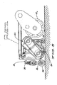
- bedknife 24 is typically mounted to the bottom of a triangular bedbar 186 that is itself attached to pivotal support arms 188 at either side of reel cutting unit 18.
- Support arms 188 pivot about a pivot axis identified as 190.
- Bedknife adjusters 32 work, in a known manner, by pivoting support arms 188 about pivot axis 190 in the direction of arrows C in Fig. 20.
- bedknife 24 As cutting reel 22 wears, the outside diameter of reel 22 shrinks and the distance between bedknife 24 and the outside diameter of reel 22 grows. When this distance becomes too large, the quality of cut is adversely affected. Thus, it is periodically necessary to rotate bedknife 24 in a direction (i.e. a counter-clockwise direction in Fig. 20) which moves bedknife 24 upwardly towards reel 22 to compensate for wear on reel 22. Again, this is the basic purpose of bedknife adjusters 32 and the use of such adjusters for this type of adjustment is well known in the art.
- prior art reel mowers of this type having a pivotal bedknife which pivots towards the cutting reel to compensate or adjust for reel wear
- the bedbar/bedknife combination would typically pivot about a pivot axis located generally at the rear of bedbar 186.
- This prior art pivot axis is shown in Fig. 20 as 192.
- the Applicants have discovered that the placement of prior art pivot axis 192 and the geometry of bedbar 186 relative to reel 22 causes the front edge of bedknife 24 to also move rearwardly relative to reel 22 as it moves upwardly.
- reel mowers of this type particularly those used for cutting greens on golf courses to very low height of cuts, it is important that the quality of cut remain consistent and not change over time. As just noted above, the quality of cut does change in prior art mowers when the bedknife is pivoted up towards the cutting reel to compensate for wear.
- This invention relates to a new location 190 for the pivot axis for the bedbar 186/bedknife 24 combination that is raised and slightly to the rear of the usual location 192 for this pivot axis.
- This new location has been selected, in conjunction with the geometry of the bedbar 186/bedknife 24 combination in relation to cutting reel 22, so that the rearward shifting of the line of contact between bedknife 24 and reel 22 does NOT occur.
- the new location 190 for the pivot axis of bedknife 24 ensures that the front edge of bedknife 24 now stays in approximately the same longitudinal location (within about 0.005 inches) relative to cutting reel 22 as the front edge of bedknife 24 rises. This ensures that the quality of cut remains much more consistent even as bedknife 24 is adjusted to compensate for reel wear.
- Bedknife 24 has been shown as a separate component on the bottom of bedbar 186 to allow ease cf removal of bedknife 24 for sharpening or replacement.
- bedbar 186 and bedknife 24 could be integrally formed with one another or bedkhife 24 could be supported in some other fashion for pivoting motion on reel cutting unit 18.
- the pivotal bedknife mounting disclosed herein could also be used on reel mowers carried on or formed as part of riding mowers.
- an improved back plate for a reel cutting unit is shown generally as 200.
- the back plate has an upper portion 202 and a lower lip 204 protruding forwardly and downwardly from upper portion 202.
- Upper portion 202 has a closed, tubular cross-sectional configuration in the form of a hollow beam to provide strength.
- Lower lip 204 is solid, rather than being hollow, and is relatively thin compared to the thickness of upper portion 202.
- back plate 200 can be extruded in one piece out of aluminum.
- back plate 200 is light, but yet strong because of the hollow beam configuration of upper portion 202.
- Back plate 200 can be made sufficiently strong so that it alone will provide sufficient strength to unite side plates 24 without having the usual additional crossmembers or stringers that normally are secured at each end to side plates 24 to provide strength.
- Back plate 200 as disclosed herein can be used on reel cutting units for walk reel mowers or for riding mowers.
Abstract
Description
- This invention relates to a reel cutting unit for a reel mower, which comprises:
- (a) a reel cutting unit frame comprising spaced side plates connected to an arcuate back plate;
- (b) a helically bladed cutting reel rotatably journal-led between the side plates and positioned in front of the back plate;
- (c) a bedknife extending between the side plates along the length of cutting reel for cooperating with the cutting reel to cut grass, the bedknife being pivotaliy adjustable relative to the side plates to compensate for wear in the cutting reel.
- Walk reel mowers are known for precision cutting of grass and the like, such as the grass found on golf greens. Such reel mowers typically have a frame which carries a reel cutting unit. A handle assembly extends upwardly and rearwardly from the frame to allow an operator who walks behind the mower to guide and operate the mower. The handle assembly includes various controls for allowing the operator to selectively engage and disengage the traction drive of the mower as well as the reel cutting unit.
- In many reel mowers, whether they be walk reel mowers or riding reel mowers, it is common to pivot the bedknife towards the cutting reel to compensate for wear in the cutting reel, note for example
US patent 2,329,952 to Speiser. This has the effect of longitudinally moving the front edge of the bedknife from the position it occupies when the cutting reel is not worn. For example, in a cutting reel with a relatively unworn reel, the front edge of the bedknife might typically be behind the center of the cutting reel by a certain amount. When the reel wears and the bedknife is pivoted up to maintain proper clearance to the cutting reel, this behind the center distance will change. - The Applicants have found that this change in the behind the center distance of the bedknife affects how aggressively the cutting reel cuts. Thus, after the reel becomes worn and the bedknife is adjusted in the manner just described, the cutting unit will cut differently than when the reel was new and the bedknife had not been adjusted from its initial orientation. This change in the quality of the cutting is not desirable. It would be best for the cutting unit to cut approximately the same regardless of how worn the cutting reel has become and whether or not the bedknife has been adjusted to compensate for this wear.
- In accordance with the invention as defined in independent claim 1, there is provided a reel cutting unit for a reel mower which comprises a reel cutting unit frame comprising spaced side plates connected to an arcuate back plate. A helically bladed cutting reel is rotatably journalled between the side plates and positioned in front of the back plate. A bedknife extends between the side plates along the length of cutting reel for cooperating with the cutting reel to cut grass. The bedknife is pivotally adjustable relative to the side plates to compensate for wear in the cutting reel. The pivot axis of the bedknife is chosen such that the front edge of the bedknife stays in approximately the same longitudinal location relative to the cutting reel as the front edge of the bedknife rises upwardly to compensate for wear in the cutting reel.
- This invention will be described hereafter in the Detailed Description, taken in conjunction with the following drawings, in which like reference numerals refer to like elements or parts throughout.
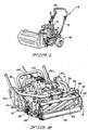
- Fig. 1 is a perspective view of a first embodiment of a walk reel mower according to this invention, with the grass collecting basket being shown on the reel cutting unit in this view but with such a basket not being shown in any of Figs. 2-9 for the purpose of clarity;
- Fig. 2 is a perspective view of a portion of the walk reel mower shown in Fig. 1, particularly illustrating the reel cutting unit and the pair of inclined rigid links that mount the cutting unit carrier frame for rolling motion relative to the reel mower frame;
- Fig. 3 is a front elevational view of a portion of the walk reel mower shown in Fig. 1, particularly illustrating the reel cutting unit and the focal point F of the rigid links that mount the cutting unit carrier frame to the reel mower frame;
- Fig. 4 is a right side elevational view of a portion of the walk reel mower shown in Fig. 1;
- Fig. 5 is a left side elevational view of a portion of the walk reel mower shown in Fig. 1;
- Fig. 6 is a top plan view of a portion of the walk reel mower shown in Fig. 1, particularly illustrating the self-lubricating drive shaft that transfers drive from the gearbox located on the reel mower frame to the cutting reel;
- Fig. 7 is a diagrammatic side elevational view of the walk reel mower shown in Fig. 1, particularly illustrating the pitching motion of the reel cutting unit about a substantially horizontal transverse axis;
- Figs. 8 and 9 are diagrammatic front elevational views of the walk reel mower shown in Fig. 1, particularly illustrating the rolling motion of the reel cutting unit about a substantially horizontal longitudinal axis;
- Fig. 10 is a perspective of an integrated gearbox that provides both the traction and reel drives for the walk reel mower shown in Figs. 1 and 14;
- Fig. 11 is an exploded perspective view of the gearbox shown in Fig. 10;
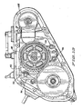
- Fig. 12 is an enlarged perspective view of the gearbox shown in Fig. 10, but with the side covers of the gearbox having been removed to illustrate the interior of the gearbox and particularly to illustrate the traction drive clutch drum, the drive gear interconnecting the ring gear and the input gear of the differential, the traction drive band brake surrounding the traction drive clutch drum, and the output gear on the cutting reel drive shaft;
- Fig. 13 is an enlarged side elevational view of the gearbox shown in Fig. 10, with Fig. 13 being similar to Fig. 12 in that the side covers of the gearbox have been removed to illustrate the interior of the gearbox to thereby illustrate the same components as are shown in Fig. 12;
- Fig. 14 a perspective view of a second embodiment of a walk reel mower according to this invention, with the grass collecting basket being shown detached from the reel cutting unit in this view and sitting on the ground in advance of the reel cutting unit, this embodiment of the walk reel mower having a single, integrated control handle for controlling both the reel and traction drives and another control handle for actuating the parking brake;
- Fig. 15 is a perspective view of the single, integrated control handle shown in Fig. 14 for controlling both the reel and traction drives;
- Fig. 16 is an exploded perspective view of the single, integrated control handle shown in Fig. 14 for controlling both the reel and traction drives;
- Fig. 17 is a perspective view of a portion of the walk reel mower shown in Fig. 14, particularly illustrating the mounting on the reel mower frame for supporting the grass collecting basket;
- Fig. 18 is a top plan view of that portion of the walk reel mower shown in Fig. 17;
- Fig. 19 is a side elevational view of that portion of the walk reel mower shown in Fig. 17;
- Fig. 20 is a side elevational view of the reel cutting unit used in the walk reel mower of this invention, particularly illustrating the pivotal mount for the bedknife; and
- Fig. 21 is a side elevational view of the reel cutting unit used in the reel mower of this invention with one of the side plates removed to show the cross-sectional shape of the back plate of the reel cutting unit frame.
- This invention relates to a
walk reel mower 2 having a reel cutting unit for cutting grass. The term "walk reel mower" is used in this application to refer to awalk reel mower 2 in which the operator walks behindwalk reel mower 2 aswalk reel mower 2 is operated. The operator is not supported or carried bywalk reel mower 2 as would be the case with a riding reel mower. More particularly, walkreel mower 2 is suited for mowing grass at low heights of cut where precision cutting is required, such as on the greens of a golf course. However, the various aspects of the invention disclosed herein are not limited for use on a walk reel mower for mowing only golf greens, but can be used on walk reel mowers for mowing other turf areas as well. - Fig. 1 provides an overall view of one embodiment of a
walk reel mower 2 according to this invention.Walk reel mower 2 includes aframe 4 on which apower source 6, such as an internal combustion engine, is carried.Other power sources 6 could be used in place of the internal combustion engine or in addition to the internal combustion engine. For example, the internal combustion engine could be replaced by an electric motor driven by a rechargeable battery pack carried onreel mower frame 4 ofwalk reel mower 2. Alternatively, a hybrid internal combustion engine/battery pack power system could be used for supplying electrical power to an electric motor. Thus, the nature ofpower source 6 is not important to the various aspects of the invention disclosed herein as long as such apower source 6 has a rotating output shaft from which power can be drawn. -
Walk reel mower 2 includes a U-shaped, upwardly extendinghandle assembly 8 that is connected at its lower end toreel mower frame 4 ofwalk reel mower 2.Handle assembly 8 includes an upper cross bar 10 which the operator can grip to guidewalk reel mower 2 during operation thereof. Various operational controls are provided onhandle assembly 8 for allowing the operator to control the operation of the traction drive and cutting reel drive ofwalk reel mower 2. The embodiment of Fig. 1 discloses a first set of such controls while the embodiment of Fig. 14 discloses a second set of such controls. -
Walk reel mower 2 is propelled across the ground by a traction drive including asplit traction drum 12 rotatably carried at the rear ofreel mower frame 4.Traction drum 12 is split, as is conventional, into two halves, a left half 121 and a right half 12r. Traction drum halves 121 and 12r are independently driven by a differential to allow a difference in rotational speed between traction drum halves 121 and 12r when walkreel mower 2 is turning. - The
rotational shaft 141 and 14r for each traction drum half 121 or 12r is extended outwardly to mount atransport wheel 16 on each side ofwalk reel mower 2.Transport wheels 16 are used only whenwalk reel mower 2 is being driven from one site to another. When walkreel mower 2 is being used to cut grass,transport wheels 16 are removed.Walk reel mower 2 is then supported and driven solely bytraction drum 12. - If desired, traction drum halves 121 and 12r could be replaced by separate left and right drive wheels engaging the ground in the manner of
transport wheels 16. In this case, such drive wheels would not be removed and would support walkreel mower 2 for movement over the ground at all times. - A
reel cutting unit 18 of generally conventional design is carried on the front ofreel mower frame 4. Reel cuttingunit 18 includes a reelcutting unit frame 19 comprising spacedside plates 20 connected to an arcuate back plate (not shown in Fig. 2). A helically bladed cuttingreel 22 is rotatably journalled betweenside plates 20 and is positioned in front of the back plate. As cuttingreel 22 rotates, the reel blades sweep standing grass against a sharpenedbedknife 24 to thereby sever the grass.Bedknife 24 extends betweenside plates 20 along the length of cuttingreel 22.Bedknife 24 is shown in Figs. 4, 5 and 19. - Reel cutting
unit 18 is self supporting for rolling over the ground or turf by front andrear rollers side plates 18. The height of cut can be adjusted in any conventional manner. For example,front roller 26 can be moved up and down relative toside plates 18 by a threadedheight adjusting mechanism 30 carried on eachside plate 18. In addition, bedknife 24 can be adjusted relative to cuttingreel 22 bybedknife adjusters 32 carried on the top ofreel cutting unit 18. Suchbedknife adjusters 32 are designed to maintain a constant spring force onbedknife 24 throughout the life of cuttingreel 22. - One aspect of this invention relates to how
reel cutting unit 18 is supported onreel mower frame 4. Reel cuttingunit 18 is allowed to float or move relative to reelmower frame 4 about two axes. First,reel cutting unit 18 can roll about a longitudinal axis, i.e. a fore-and-aft horizontal axis x. See Fig. 8. Second,reel cutting unit 18 can pitch about a transverse axis, i.e. a side-to-side horizontal axis y which is coaxial with the axis of cuttingreel 22. See Fig. 7. Motion ofreel cutting unit 18 about the axes x and y allowreel cutting unit 18 to better conform to the contours of the ground being cut to avoid scalping. This is particularly important when cutting golf greens, especially those found on newer golf courses in which the greens often have pronounced undulations. - Reel cutting
unit 18 is supported in the above described manner by a generally U-shaped cuttingunit carrier frame 34. Cuttingunit carrier frame 34 includes atransverse cross member 36 having downwardly extending,vertical support arms 38 at either end thereof. Eachvertical support arm 38 passes downwardly through a slot in a top wall ofreel cutting unit 18 to lie adjacent oneside plate 20. The lower end of eachvertical arm 38 includes an inwardly protrudingcircular hub 40 which rotatably engages or journals the shaft of cuttingreel 22. Thus, during operation ofwalk reel mower 2,reel cutting unit 18 can pivot or rock back and forth in the direction of the arrows A in Fig. 7 by pivoting or rocking on the inwardly protrudinghubs 40 ofvertical support arms 38. - Cutting
unit carrier frame 34 is further suspended fromreel mower frame 4 by at least one pair of inclinedrigid links 42. Referring to Fig. 3, the upper end of eachlink 42 is pivotally secured to reelmower frame 4 while the lower end of eachlink 42 is pivotally secured to crossmember 36 of cuttingunit carrier frame 34. Eachlink 42 is located offset from the longitudinal centerline ofreel cutting unit 18 so thatlinks 42 are on opposite sides of the centerline, i.e. onelink 42 is offset to the left of the centerline while theother link 42 is offset to the right of the centerline.Links 42 are further inclined inwardly relative to one another and relative to a vertical line passing through the upper end of eachlink 42. In other words, the lower end of eachlink 42 is closer to the longitudinal centerline ofreel cutting unit 18 than is the upper end of eachlink 42. - Accordingly, lines drawn through
links 42 will be inclined towards each other and will eventually intersect at a focal point F shown in Fig. 3. Focal point F lies along the longitudinal axis x about which the cutting unit rolls. In addition, focal point F at which the lines of action oflinks 42 intersect is selected to be at the center ofbedknife 24, at least whenreel cutting unit 18 is sitting on flat and level ground. This is achieved by controlling the placement and angle of inclination oflinks 42. -
Links 42 are provided in a first pair oflinks 42 which attach to the front ofcress member 36, and in a duplicate second pair of links 42' which attach to the rear ofcross member 36. See Fig. 6.Links 42 in the first pair of links are contained in a first transverse plane while links 42' in the second pair of links are contained in a second transverse plane that is offset from the first plane by the thickness ofcross member 36. Using two pairs ofduplicate links 42, 42' as disclosed herein suspendsreel cutting unit 18 in an efficient and durable manner without putting undue stress on any single pair of links. - While a suspension system for
reel cutting unit 18 has been shown which comprises a duplicate pair of inclined,rigid links 42, it would be possible to use only a single pair oflinks 42. In addition, four pivotal links could also be used in an arrangement where each link was located adjacent one corner ofreel cutting unit 18 and extended upwardly therefrom to some overlying portion ofreel mower frame 4. Each link would again be inclined inwardly to point towards a common focal point F located at the center ofbedknife 24. - Referring now to Figs. 7-9, the various permitted motions of
reel cutting unit 18 during operation ofwalk reel mower 2 are illustrated. Fig. 7 shows the pitching motion ofreel cutting unit 18 about the transverse axis y, the phantom line positions illustrating the pitching motion. Figs. 8 and 9 illustrate the rolling motion ofreel cutting unit 18 about the longitudinal axis x. The rolling motion is depicted by the arrows B in Figs. 8 and 9. Fig. 8 illustratesreel cutting unit 18 having rolled to one side while Fig. 9 illustratesreel cutting unit 18 having rolled to the opposite side. Note the pivoting of the pair oftransverse links 42 which permits this rolling motion. - The Applicants' have found the use of at least a pair of inwardly, inclined
rigid links 42 to supportreel cutting unit 18 for rolling motion to be particularly advantageous. Becauselinks 42 point towards a focal point F located at the center ofbedknife 24 whenreel cutting unit 18 is level, it is as if the entirereel cutting unit 18 is rolling about the longitudinal axis x containing focal point F. Accordingly, scalping or scuffing of the turf is minimized asreel cutting unit 18 rolls. - It is preferred that the focal point F for the
rigid suspension links 42 be located at the center ofbedknife 24. However, other focal points F could also be used, such as a focal point F located at the surface of or slightly below the surface of the ground. It is desirable that the focal point F be low relative to reel cuttingunit 18 and to the ground to minimize turf scalping or scuffing. Using a focal point F at the center ofbedknife 24 accomplishes both keeping the focal point low as well as keeping the focal point F longitudinally centered relative to reel cuttingunit 18. However, other focal points F could be used although such focal points are desirably kept relatively low with respect to reel cuttingunit 18. - One advantage of the suspension system described above is that all "floating movement" of
reel cutting unit 18 is achieved by a rigid suspension system, i.e. therigid links 42 as well as the rigid cuttingunit carrier frame 34. Thus, when the operator wishes to tipreel cutting unit 18 up off the ground by pushing downwardly onhandle assembly 8 to raise the front end ofwalk reel mower 2,reel cutting unit 18 will rise immediately without having to take up any slack in flexible chains or the like, as is required in more traditional mowers that often support the reel cutting unit with chains. Thus, the unevenness and jerkiness encountered in prior art walk reel mowers during this operation, i.e. relatively easy lifting until the chains tighten and then the need for a greatly increased force to raisereel cutting unit 18, is avoided. Thus, walkreel mower 2 of this invention has the solid feel and handling of a walk reel mower in which the entirereel cutting unit 18 is rigidly carried onwalk reel mower 2, but yet provides much of the floating motion permitted by a chain type suspension system forreel cutting unit 18. - Another aspect of this invention relates to a greatly simplified
gearbox 44 for providing atraction drive 46 for poweringtraction drum 12 as well as areel drive 48 for powering cuttingreel 22. The clutches used to initiate traction drive 46 andreel drive 48 are all contained withingearbox 44. A differential 54 and much of the speed reduction gearing required fortraction drive 46 are contained ingearbox 44 as well. Finally,gearbox 44 includes aparking brake 56. The clutches required to actuate traction drive 46 andparking brake 56 are simple, tightenable band brakes. - Both of the embodiments shown in Figs. 1 and 14 use this
gearbox 44 withgearbox 44 being generally identical in both embodiments.Gearbox 44 shown in Fig. 1 includes avent 45 which is not present ingearbox 44 shown in Fig. 14. Other than for this difference,gearboxes 44 shown in Figs. 1 and 14 are identical. - Fig. 10 is a perspective view'of the
improved gearbox 44 of this invention withgearbox 44 having been removed fromwalk reel mower 2. Fig. 11 is an exploded perspective view of theimproved gearbox 44 of this invention.Gearbox 44 will be described primarily, though not exclusively, with reference to these figures, and mostly with reference to Fig. 11. - Referring now to Fig. 11,
gearbox 44 includes atraction drive shaft 58 extending acrossgearbox 44. Asun gear 60 is carried ontraction drive shaft 58. In addition, aplanetary gear carrier 62 having a plurality of planetary gears 64 (only one of which is shown in Fig. 11) is rotatably journalled ontraction drive shaft 58 byneedle bearings 66. There are three planetary gears 64 and each planetary gear 64 is rotatably carried onplanetary gear carrier 62 by a pin ordowel 68. -
Traction drive shaft 58 is driven from the output shaft ofpower source 6 by a power source gear (not shown) that extends intogearbox 44 through ahousing opening 70. This power source gear is placed between and meshes with afirst input gear 102 keyed to traction driveshaft 58 and asecond input gear 100 carried on areel drive shaft 98. Thus, wheneverpower source 6 is operating,traction drive shaft 58 is rotating,sun gear 60 is rotating, and planetary gears 64 are orbiting aroundsun gear 60 such thatplanetary gear carrier 62 is also continuously rotating. - One end of
planetary gear carrier 62 includes agear 72 that is engaged with an internal gear formed in the bore of a traction driveclutch drum 74. Thus, wheneverpower source 6 is operating, traction driveclutch drum 74 normally rotates withtraction drive shaft 58,sun gear 60, planetary gears 64 andplanetary gear carrier 62. However, when traction driveclutch drum 74 is rotating, no power is being supplied totraction drum 12. - An
internal ring gear 76 is concentrically received aroundplanetary gear carrier 62 and is capable of independent rotation relative toplanetary gear carrier 62 sincering gear 76 is supported on abushing 78 interposed betweenplanetary gear carrier 62 andring gear 76. Again, when no traction drive is present ontraction drum 12 but withpower source 6 operating, planetary gears 64, will crawl around the inside ofring gear 76 as planetary gears 64 are rotated, butring gear 76 will itself remain stationary. -
Ring gear 76 includes a parking brakeclutch drum 80 and atraction drive gear 82 affixed thereto or made integral therewith.Traction drive gear 82 is connected to the input gear 84 of a generally conventional differential 54.Differential 54 includes first andsecond output shafts 861 and 86r which are adapted to independently drive traction drum halves 121 and 12r.Differential 54 can be a Peerless differential, Model No. 100-207. - In order to transmit drive to
traction drum 12, atraction band brake 88 is located around traction driveclutch drum 74. Normally,traction band brake 88 is in a loosened state. However, when various controls onhandle assembly 8 are manipulated, as will be described hereafter,traction band brake 88 can be tightened around traction driveclutch drum 74 by rotating alever arm 90, to which the ends oftraction band brake 88 are connected as illustrated at 92. This rotating action oflever arm 90 moves one end oftraction band brake 88 relative to the other end oftraction band brake 88 to tightentraction band brake 88 around traction driveclutch drum 74. - When
traction band brake 88 is so tightened, rotation of traction driveclutch drum 74 and ofplanetary gear carrier 62 is stopped. However,traction drive shaft 58,sun gear 60, and planetary gears 64 are all still rotating. The rotation of planetary gears 64 is now transmitted to ringgear 76 to rotatering gear 76 and hence rotatetraction drive gear 82 that is fixed toring gear 76. This, in turn, transmits the drive through differential 54 to theoutput shafts 861 and 86r of differential 54. - The outer end of each
differential output shaft 861 and 86r is located outsidegearbox 44 where it is connected by an enclosed belt orchain drive 901 and 90r to one of theshafts 141 and 14r for one of traction drum halves 121 and 12r. Thus, whenevertraction band brake 88 is selectively tightened by the operator whilepower source 6 ofwalk reel mower 2 is operating, drive frompower source 6 will be transmitted through the drive reduction provided by the planetary gearing and ring gear, through differential 54, and through the individual belt or chain drives 901, and 90r to theshafts 141 and 14r of traction drum halves 121 and 12r. - Much of the drive reduction needed for traction drum halves 121 and 12r is accomplished by the reduction provided within
gearbox 44 itself. However, some reduction also occurs within the belt or chain drives 901 and 90r which connect the differential output shafts with the shafts for traction drum halves 121 and 12r. This reduction within the belt or chain drives 901 and 90r is provided by sizing the input and output pulleys or sprockets differently from one another to further reduce the speed of the differential output shafts. However, if so desired, a planetary gear drive could be provided withingearbox 44 having multiple planetary stages such that the planetary gear drive itself provides substantially all of the desired drive reduction. - A
parking brake 56 forwalk reel mower 2 is conveniently and simply formed by the parking brakeclutch drum 80 fixed to or formed withring gear 76 along with a second,parking band brake 94 included withingearbox 44.Parking band brake 94 can be tightened in much the same manner astraction band brake 88, i.e. by pivoting alever arm 96 to pull one end of the band brake relative to the other end of the band brake in a direction that tightens the band brake around the clutch drum. This is done by any suitable operational control provided on, walkreel mower 2 and any suitable linkage for providing rotation oflever arm 96. - When the parking brake control is actuated and
parking band brake 94 is tightened,parking band brake 94 grips parking brakeclutch drum 80 secured to ringgear 76 with sufficient force to holdring gear 76 against rotation caused bywalk reel mower 2 rolling down a typical incline found on a golf course or the like. This gripping force is chosen to holdwalk reel mower 2 in place assumingtraction drive 46 is not operating., If traction drive 46 is operating,parking band brake 94 will not provide sufficient force to holdring gear 76 as the force provided byparking band brake 94 will be overpowered by the force of traction drive 46 onring gear 76. However,parking brake 56 is only intended to be used when traction drive 46 is disengaged and no traction force is being transmitted toring gear 76. In this case, the gripping force provided byparking band brake 94 is sufficient to holdring gear 76 against any rotation which might be induced bywalk reel mower 2 rolling down an incline, thus keepingwalk reel mower 2 stationary against unintended movement. - The
same gearbox 44 which provides atraction drive 46 fortraction drum 12 and aparking brake 56 forwalk reel mower 2 also provides areel drive 48 for cuttingreel 22. Thisreel drive 48 will now be described, again with reference to the exploded perspective view of Fig. 11. - A
reel drive shaft 98 is rotatably journalled ingearbox 44 and is parallel to traction driveshaft 58.Reel drive shaft 98 includes aninput gear 100 which is continuously rotated wheneverpower source 6 is operating. Thisinput gear 100 is continuously rotated by the same power source gear (not shown) that is driven by the engine, this power source gear mating with and driving both input gears 100 and 102. Thus, whenpower source 6 is operating and the power source gear (not shown) contained ingearbox 44 is rotating, the engagement between this power source gear andinput gear 100 onreel drive shaft 98 causesinput gear 100 onreel drive shaft 98 to be continuously rotated. -
Input gear 100 onreel drive shaft 98 does not continuously rotatereel drive shaft 98 as it is supported onreel drive shaft 98 by abearing 104. Thus,input gear 100 onreel drive shaft 98 can rotate whilereel drive shaft 98 is stationary. The operator can selectively placereel drive shaft 98 into operation by operating a control onwalk reel mower 2, which control will be described in more detail hereafter, to slide acone clutch 106 into engagement withinput gear 100 onreel drive shaft 98. Cone clutch 106 is slidably, but non-rotatably affixed, to reeldrive shaft 98. Thus, whencone clutch 106 is slid alongreel drive shaft 98 and into engagement withinput gear 100,cone clutch 106 will transmit the drive frominput gear 100 to reeldrive shaft 98 to begin rotatingreel drive shaft 98.Reel drive shaft 98 includes anoutput gear 108 on the other end thereof from which the drive for cuttingreel 22 may be taken. Thisoutput gear 108 is not shown in Fig. 11, but is shown in Figs. 12 and 13. - The
integrated gearbox 44 disclosed herein has many advantages. It conveniently locates both the traction and reel drives 46 and 48 within a single gearbox. This avoids the cluttered look of prior art walk reel mowers many of which use separate gearboxes for these drives. It also locates theclutches gearbox 44 can be lubricated with oil, both the traction and reel drives 46 and 48 will be kept lubricated together, without having to keep separate gearboxes lubricated. - In addition, considering just traction drive 46 alone, the
single gearbox 44 houses both a planetary gear reduction drive as well as differential 54. This avoids having to place differential 54 intraction drum 12 itself, as in older walk reel mower designs. In addition, the clutch 88 for initiatingtraction drive 46 is a simple band brake which is tightened around traction driveclutch drum 74 to cause the drive of planetary gears 64 to be transmitted up throughring gear 76 rather than toplanetary gear carrier 62. Thus, traction drive 46 is compact, simple and durable. Accordingly, traction drive is transmitted totraction drum 12 in a highly efficient and easy to operate manner. - Moreover, as previously described, a
parking brake 56 is easily incorporated into the unit by forming anotherclutch drum 80 withring gear 76 and using asecond band brake 94 to grip this clutch drum. Again, this is a compact, simple and durable structure. - The
output gear 108 located onreel drive shaft 98 is coupled to cuttingreel 22 through a first belt orchain drive 110 that extends downwardly fromgearbox 44 to a point abovereel cutting unit 18. This first belt orchain drive 110 is preferably arranged to provide a 1 to 1 drive, but other than a 1 to 1 drive could be used. This first belt orchain drive 110 is located generally overreel cutting unit 18 due to the location ofgearbox 44. Thus, it is necessary to transfer drive from the lower end of first belt orchain drive 110 over to one side ofreel cutting unit 18 and then down to the shaft of cuttingreel 22. The drive must be transferred and kept in proper operation even thoughreel cutting unit 18 can float or move relative to reelmower frame 4 through motion with respect to two axes, i.e. the x and y axes described above. - Referring now to Fig. 6, the drive is transferred from the first belt or
chain drive 110 that extends downwardly fromgearbox 44 by a transversely extendingdrive shaft 112 arranged abovereel cutting unit 18. Driveshaft 112 comprisesflexible joints 114 at either end, in the nature of universal couplings, which are formed from a solid piece of stainless steel material having a spiral slot or groove, formed therein. Similar joints are commercially available from Helical Products of Santa Maria, California. The joints are referred to by Helical Products as flexible helix beam couplers. - A stub shaft 116 is secured to each joint and extends inwardly so that stub shafts 116 on the
opposed joints 114 point towards one another, not away from one another. Each stub shaft 116 has a non-circular cross-sectional configuration. In other words, each stub shaft 116 has an outer periphery in the form of a square or hex shape or the like. Each stub shaft 116 is received within the interior bore 118 of anintermediate coupler 120. Bore 118 ofintermediate coupler 120 is shaped to mate with the cross-sectional configuration of stub shafts 116. Thus, if stub shafts 116 have a hex head configuration, bore 18 will have a hex head configuration as well. - As should be apparent, each stub shaft 116 is slidably received within
intermediate coupler 120 so that stub shafts 116 can move in and out relative tointermediate coupler 120 asreel cutting unit 18 rolls about the x axis. Stub shafts 116 andintermediate coupler 120 are designed so that stub shafts 116 never come out ofintermediate coupler 120 asreel cutting unit 18 rolls during operation ofwalk reel mower 2 as this would disrupt the drive provided bydrive shaft 112. Stub shafts 116 are merely able to slide back and forth withinintermediate coupler 120 to accommodate the maximum permissible amount of rolling motion without ever disengagingintermediate coupler 120. Asintermediate coupler 120 and stub shaft 116 nearest the first belt orchain drive 110 fromgearbox 44 rotate, this rotation will be transmitted throughintermediate coupler 120 to stub shaft 116 adjacent the left side ofreel cutting unit 18. From that point, the drive can be transferred to the shaft of cuttingreel 22 by a second 1 to 1 belt orchain drive 122. See Fig. 5. - Desirably, joints 114 as well as
intermediate coupler 120 are made from materials which do not require external lubrication. For example,coupler 120 is made from a nylon material impregnated with a non-oil based lubricant, such as molybdenum disulfide. This, material provide its own lubrication without requiring the material to be immersed or bathed with oil. Using such self-lubricating materials indrive shaft 112 is an advantage in a walk reel mower as there is no possibility of an oil leak that might damage the grass. Thus, driveshaft 112 disclosed herein is an efficient and environmentally friendly structure for driving cuttingreel 22 fromgearbox 44, even thoughreel cutting unit 18 can itself pitch and roll relative togearbox 44. - Drive
shaft 112 could also be used on reel mowers carried on or formed as part of riding mowers. - Another aspect of this invention relates to the operational controls for
walk reel mower 2. Referring to Fig. 14, a first pivotal control handle 124 is carried onhandle assembly 8 ofwalk reel mower 2 on one of the handle tubes. This first control handle 124 actuatesparking brake 56. Whenfirst control handle 124 is pivoted from one position to another, a control linkage is pulled which causes the rotation oflever arm 96 forparking band brake 94. This causesparking band brake 94 to tighten on parking brakeclutch drum 80 to preventring gear 76 from turning during non-powered, inadvertent movement ofwalk reel mower 2, such as whenwalk reel mower 2 might roll down an incline. Movement of first control handle 124 back to its normal position will loosenparking band brake 94 andrelease parking brake 56. - Normally, when
first control handle 124 is pivoted downwardly and forwardly relative to handleassembly 8,parking brake 56 is not actuated. Whenfirst control handle 124 is pivoted rearwardly and upwardly relative to handleassembly 8,parking brake 56 is actuated. The position of first control handle 124 in Fig. 14 illustrates the position in whichparking brake 56 is actuated. - A single, second control handle 126 is provided for operating both
traction drive 46 and cuttingreel 22. This is particularly advantageous and an improvement over prior art walk reel mowers. Second control handle 126 is shown in detail in Figs. 15 and 16. - A
control housing 128 is secured to that handle tube which does not mountfirst control handle 124. Asemi-circular sleeve 130 is provided for being received around the handle tube for attachingcontrol housing 128 to the handle tube. A substantially horizontal, fixedpivot pin 132 extends through one side wall ofcontrol housing 128 and is received in an alignedbore 134 in an intermediate wall incontrol housing 128. This pivot pin - 132 serves as a fixed pivot axis forsecond control handle 126. - Second control handle 126 is pivotally mounted on fixed
pivot pin 132 so as to rotate around fixedpivot pin 132. The lower end of second control handle 126 has ayoke 134. As shown in Fig. 16,yoke 134 has spacedlegs 136 which haveopenings 138 for journalling second control handle 126 on fixedpivot pin 132.Yoke 134 includes aradially extending arm 140 that is attached to one end of aspring 142. The other end ofspring 142 is attached to a cable orlinkage 144 which actuateslever arm 90 ontraction band brake 88 to actuatetraction drive 46. - Pivoting second control handle 126 downwardly about the pivot axis formed by fixed
pivot pin 132, i.e. in the direction of the arrow C in Fig. 14, pulls upwardly throughspring 142 oncable 144 that actuateslever arm 90 ontraction band brake 88. This causestraction band brake 88 to be tightened. Tighteningtraction band brake 88 stops or locks upplanetary gear carrier 62. In turn, this allows planetary gears 64 to rotatering gear 76. Thus, rotating second control handle 126 downwardly and forwardly places walkreel mower 2 into movement by actuatingtraction drive 46. second control handle 126 is shown in Fig. 14 in a position in which traction drive 46 is engaged. - Second control handle 126 further includes a selectively
operable toggle member 146 on the top thereof for actuating cuttingreel 22. Whentoggle member 146 is located coaxially in line withsecond control handle 126, cuttingreel 22 is stationary. However, if the user first toggles thetoggle member 146 to one side ofsecond control handle 126, so thattoggle member 146 is now inclined relative to the axis ofsecond control handle 126, cuttingreel 22 will be placed in operation when second control handle 126 is pivoted in a direction that also engagestraction drive 46. - A
reciprocal rod 148 is located inside second control handle 126 whichrod 148 is moved up and down relative to second control handle 126 whentoggle member 146 is toggled. The bottom oftoggle member 146 is pivotally mounted to second control handle 126 by atoggle base 150 that rotates about a transversely offsetpivot pin 152.Toggle base 150 is also pinned at 154 to the top ofreciprocal rod 148. Whentoggle member 146 is coaxially aligned withsecond control handle 126, the pinnedconnection 154 toreciprocal rod 148 is raised above the offsetpivot pin 152, thereby drawingreciprocal rod 148 upwardly relative tosecond control handle 126. Whentoggle member 146 is toggled to one side relative to second control handle 126 as shown in Figs. 14-16, so that the co-axial relationship betweentoggle member 146 and second control handle 126 is no longer present, the pinnedconnection 154 toreciprocal rod 148 is now lowered relative to the offsetpivot pin 152 to be at about the same level as the offsetpivot pin 152, thereby pushingreciprocal rod 148 downwardly relative tosecond control handle 126. - A
pivotal coupling link 156 is pivotally mounted on fixedpivot pin 132 incontrol housing 128 between the spacedlegs 136 ofyoke 134 in a position underlying the lower end ofsecond control handle 126. Thispivotal coupling link 156 includes anotch 158 in one side that is sized to receive the lower end ofreciprocal rod 148 insecond control handle 126.Pivotal coupling link 156 is independently rotatable relative tosecond control handle 126, i.e.pivotal coupling link 156 does not necessarily rotate with second control handle 126 when second control handle 126 rotates. It only rotates with second control handle 126 when the lower end ofreciprocal rod 148 in second control handle 126 is lowered intonotch 158 onpivotal coupling link 156. -
Pivotal coupling link 156 is further secured to one end of aspring 160. The other end of thisspring 160 is attached to a cable orlinkage 162 which actuatescone clutch 106 onreel drive shaft 98 to actuate cuttingreel 22. Pulling upwardly on thiscable 162 rotates a bell cranklinkage 164 on top ofgearbox 44, which bell cranklinkage 164 is connected in some fashion tocone clutch 106, to slidecone clutch 106 back and forth onreel drive shaft 98. - When
toggle member 146 is toggled to the side as shown in Figs. 14-16,reciprocal rod 148 is moved down such that the lower end ofreciprocal rod 148 enters intonotch 158 incoupling link 156. When the lower end ofreciprocal rod 148 enters intonotch 158,coupling link 156 is now coupled to second control handle 126 for joint rotation therewith. Thus, rotating second control handle 126 to actuate traction drive 46 will also cause cuttingreel 22 to be placed into operation. If the operator does not toggle thetoggle member 146 to the side before rotatingsecond control handle 126, such thatreciprocal rod 148 remains in a raised position relative to second control handle 126 with the lower end ofreciprocal rod 148 being out of engagement withnotch 158 incoupling link 156, then onlytraction drive 46 is engaged, with cuttingreel 22 remaining stationary. - The integrated traction drive/cutting reel control handle 126 is advantageous over prior art walk reel mowers in which two separate control handles are sometimes provided or in which the cutting reel control handle is located down on
reel mower frame 4. In this latter situation, the operator must walk around from behindhandle assembly 8 to actuate anddeactuate cutting reel 22. This can be onerous and time-consuming to do. With the single second control handle 126 disclosed herein, the operator can separately engage and disengage cuttingreel 22 from behindhandle assembly 8 without leaving the normal operating position. - The advantages in this are best explained in reference to the use of a walk reel mower of this type in cutting golf greens or the like. When cutting a number of such greens, the operator will first cut one green. Following the cutting of one green, the operator will the drive
walk reel mower 2 to the next green. When making the trip to the next green, it is desirable that cuttingreel 22 be disengaged and only traction drive 46 be engaged. - However, as a practical manner, many operators do not disengage cutting
reel 22 during such a trip because they have to leave the operator's position to reach the control handle or lever which controls cuttingreel 22, such control handle or lever normally being present onreel mower frame 4 in front ofhandle assembly 8. To disengage cuttingreel 22, the operator first has to disengage traction drive 46, walk around in front ofhandle assembly 8 to disengage cuttingreel 22, then walk back behindhandle assembly 8 to re-engage traction drive 46 to allowwalk reel mower 2 to be driven to the next green. When the next green is reached, this procedure has to be repeated. Namely, to now engage cuttingreel 22, the operator again has to disengage traction drive 46, walk around in front ofhandle assembly 8 to now re-engage cuttingreel 22, and then walk back behindhandle assembly 8 to re-engagetraction drive 46. - This procedure is so onerous and bothersome to many operators that such operators simply don't take the time to disengage cutting
reel 22 when drivingwalk reel mower 2 from one location to another. Instead, they simply let cutting reel 22 remain powered and tipwalk reel mower 2 back on itstraction drum 12 to keepreel cutting unit 18 raised during transport. This is disadvantageous as additional wear and tear is placed onreel cutting unit 18 because it is operating at times when it need not. In addition, it is tiring to the operator to keepreel cutting unit 18 elevated off the ground during transport. - By contrast,'the single control handle 126 of this invention allows the operator to disengage cutting
reel 22 with the flick of a wrist and on the fly while traction drive 46 remains engaged. All the operator needs to do is to toggle thetoggle member 146 back to its upright, in line position with second control handle 126 andreciprocal rod 148 will leave notch 158 incoupling link 156. Thespring 160 will then causecoupling link 156 to return to its unactuated position and theactuating cable 162 will return to its position in whichcone clutch 106 is disengaged. However, traction drive 46 remains engaged. Thus, at the end of one mowing operation, walkreel mower 2 of this invention can be easily driven to another location with cuttingreel 22 being disengaged simply by flickingtoggle member 146 to its upright position. - When a new mowing location is reached, the operator must disengage traction drive 46 before re-engaging cutting
reel 22. But, with the second control handle 126 disclosed herein, this is easily done simply by rotating second control handle 126 rearwardly and upwardly onhandle assembly 8 to its normal unactuated position. Then, bothtraction drive 46 and cutting reel can be easily re-engaged by first' toggling thetoggle member 146 to one side to pushreciprocal rod 148 intonotch 158 incoupling link 156 and by then pivoting second control handle 126 downwardly and forwardly in the slot in which second control handle 126 is received. This can be done quickly and while the operator stays in the normal operational position in back ofhandle assembly 8. - If desired, a
pivotal throttle 166 can be pivotally supported on anotherpivot pin 168 carried on thesame control housing 126 that mountssecond control handle 126. Thisthrottle 166 is connected by anactuating cable 170 to the throttle onpower source 6 to allow the operator to increase or decrease the power provided bypower source 6. Placingthrottle 166 on this control housing so thatthrottle 166 is adjacent second control handle 126 groups all the controls together that relate to the actuation and control of the powered components onwalk reel mower 2. - obviously, the actuated/not actuated positions of the first and second control handles 124 and 126 could be reversed if so desired.
- In many prior art walk reel mowers of this type, the
grass basket 172 is carried onreel mower frame 4 by upwardly and forwardly inclined cylindrical pins provided at two, transversely spaced locations on the front ofreel mower frame 4. The grass basket includes a rearwardly and downwardly inclined seating groove on each side thereof for receiving one of these pins. The operator can pull the grass basket offreel mower frame 4 by pulling up and forwardly on the grass basket to remove the seating grooves from the pins. - One difficulty with this known seating groove/pin arrangement is that certain manipulation of
walk reel mower 2 can cause the pins to inadvertently disengage the grooves. For example, this sometimes happens when the operator lifts upwardly on the rear of the reel mower. If the operator lifts high enough, and if the front of the grass basket is loaded with grass clippings, the pins can be forced out of the grooves and the grass basket will become disengaged. This forces the operator to walk around and reconnect the grass basket to reelmower frame 4. - To avoid this problem, the Applicants' disclose herein two transversely spaced
sockets 174 onreel mower frame 4 for receiving seating pins 182 ongrass basket 172. This subject matter is most clearly shown in Figs. 17-19. - Each
socket 174 is attached to the front ofreel mower frame 4 generally overlyingreel cutting unit 18. Eachsocket 174 is shaped as an upwardly facingtrough 176 having spacedside walls 178 connected to each other at the bottom. For example,trough 176 could have a channel shape with vertical side walls and a flat bottom, a V-shape, a U-shape, etc.Trough 176 of eachsocket 174 is open at the front but is closed at the rear by atop wall 180. Thus,socket 174 has an upwardly open front portion and an upwardly closed rear portion. In addition,trough 176 of eachsocket 174 is upwardly inclined as it extends forwardly. See Fig. 19. - The
grass basket 172 has two rearwardly extending seating pins 182 each having a downwardly inclineddistal leg 184. Whengrass basket 172 is flat and level, the angle of inclination ofdistal leg 184 matches the angle of inclination ofsocket 174 allowingdistal leg 184 to be inserted intosocket 174 withleg 184 then being received insocket 174. Eachleg 184 fits down into onesocket 174 withleg 184 being long enough to fit down into the upwardly closed rear portion ofsocket 174 beneathtop wall 180. However, the front portion of eachsocket 174 is open at the top and is not similarly constricted by atop wall 180. - When the operator lifts up on the rear of
walk reel mower 2, the front ofwalk reel mower 2 pivots downwardly abouttraction drum 12 so thatsockets 174 begin pivoting downwardly as well. This downward pivoting motion ofsockets 174 effectively causesdistal legs 184 ofpins 182 to pivot upwardly relative tosockets 174, i.e.distal legs 184 will actually pivot upwardly at least partially through the upwardly open front portion ofsockets 174. However, since the front portion ofsockets 174 is upwardly open and is not enclosed by a top wall there is no camming force exerted ondistal legs 184 bysockets 174 that is sufficient to cam pins 182 out ofsockets 174. This avoids inadvertently disengaginggrass basket 172 fromreel mower frame 4. Accordingly,grass basket 172 will more easily stay seated onreel mower frame 4 with thesocket 174/seating pin 182 configuration shown herein than with prior art configurations, even whengrass basket 172 is loaded with grass clippings. - Referring now to Fig. 20,
bedknife 24 is typically mounted to the bottom of atriangular bedbar 186 that is itself attached topivotal support arms 188 at either side ofreel cutting unit 18.Support arms 188 pivot about a pivot axis identified as 190.Bedknife adjusters 32 work, in a known manner, by pivotingsupport arms 188 aboutpivot axis 190 in the direction of arrows C in Fig. 20. - As cutting
reel 22 wears, the outside diameter ofreel 22 shrinks and the distance betweenbedknife 24 and the outside diameter ofreel 22 grows. When this distance becomes too large, the quality of cut is adversely affected. Thus, it is periodically necessary to rotatebedknife 24 in a direction (i.e. a counter-clockwise direction in Fig. 20) which movesbedknife 24 upwardly towardsreel 22 to compensate for wear onreel 22. Again, this is the basic purpose ofbedknife adjusters 32 and the use of such adjusters for this type of adjustment is well known in the art. - In prior art reel mowers of this type having a pivotal bedknife which pivots towards the cutting reel to compensate or adjust for reel wear, the bedbar/bedknife combination would typically pivot about a pivot axis located generally at the rear of
bedbar 186. This prior art pivot axis is shown in Fig. 20 as 192. The Applicants have discovered that the placement of priorart pivot axis 192 and the geometry ofbedbar 186 relative to reel 22 causes the front edge ofbedknife 24 to also move rearwardly relative to reel 22 as it moves upwardly. Thus, in prior art reel mowers, as the bedknife was progressively pivoted up to compensate for wear in the cutting reel, the line of contact between the bedknife and the cutting reel would progressively shift rearwardly. As this happens, the Applicants further discovered that the cutting reel would become more aggressive in its cutting action and the quality of the cut would change. - In reel mowers of this type, particularly those used for cutting greens on golf courses to very low height of cuts, it is important that the quality of cut remain consistent and not change over time. As just noted above, the quality of cut does change in prior art mowers when the bedknife is pivoted up towards the cutting reel to compensate for wear.
- This invention relates to a
new location 190 for the pivot axis for thebedbar 186/bedknife 24 combination that is raised and slightly to the rear of theusual location 192 for this pivot axis. This new location has been selected, in conjunction with the geometry of thebedbar 186/bedknife 24 combination in relation to cuttingreel 22, so that the rearward shifting of the line of contact betweenbedknife 24 and reel 22 does NOT occur. In other words, in a reel mower according to this invention, asbedknife 24 pivots aboutpivot axis 190, thenew location 190 for the pivot axis ofbedknife 24 ensures that the front edge ofbedknife 24 now stays in approximately the same longitudinal location (within about 0.005 inches) relative to cuttingreel 22 as the front edge ofbedknife 24 rises. This ensures that the quality of cut remains much more consistent even asbedknife 24 is adjusted to compensate for reel wear. -
Bedknife 24 has been shown as a separate component on the bottom ofbedbar 186 to allow ease cf removal ofbedknife 24 for sharpening or replacement. However, bedbar 186 andbedknife 24 could be integrally formed with one another orbedkhife 24 could be supported in some other fashion for pivoting motion onreel cutting unit 18. The pivotal bedknife mounting disclosed herein could also be used on reel mowers carried on or formed as part of riding mowers. - Referring now to Fig. 21, an improved back plate for a reel cutting unit is shown generally as 200. The back plate has an
upper portion 202 and alower lip 204 protruding forwardly and downwardly fromupper portion 202.Upper portion 202 has a closed, tubular cross-sectional configuration in the form of a hollow beam to provide strength.Lower lip 204 is solid, rather than being hollow, and is relatively thin compared to the thickness ofupper portion 202. - Preferably, back
plate 200 can be extruded in one piece out of aluminum. Thus, backplate 200 is light, but yet strong because of the hollow beam configuration ofupper portion 202.Back plate 200 can be made sufficiently strong so that it alone will provide sufficient strength to uniteside plates 24 without having the usual additional crossmembers or stringers that normally are secured at each end toside plates 24 to provide strength.Back plate 200 as disclosed herein can be used on reel cutting units for walk reel mowers or for riding mowers. - Various other modifications of this invention will be apparent to those skilled in the art. Accordingly, the invention is to be limited only by the appended claims.
Claims (1)
- A reel cutting unit for a reel mower, which comprises:(a) a reel cutting unit frame comprising spaced side plates connected to an arcuate back plate;(b) a helically bladed cutting reel rotatably journal-led between the side plates and positioned in front of the back plate;(c) a bedknife extending between the side plates along the length of cutting reel for cooperating with the cutting reel to cut grass, the bedknife being pivotaliy adjustable relative to the side plates to compensate for wear in the cutting reel; and(d) characterized in that the pivot axis of the bedknife is chosen such that the front edge of the bedknife stays in approximately the same longitudinal location relative to the cutting reel as the front edge of the bedknife rises upwardly to compensate for wear in the cutting reel.
Applications Claiming Priority (2)
| Application Number | Priority Date | Filing Date | Title |
|---|---|---|---|
| US21413300P | 2000-06-26 | 2000-06-26 | |
| EP01948728A EP1296549B1 (en) | 2000-06-26 | 2001-06-26 | Walk reel mower |
Related Parent Applications (2)
| Application Number | Title | Priority Date | Filing Date |
|---|---|---|---|
| EP01948728.9 Division | 2001-06-26 | ||
| EP01948728A Division EP1296549B1 (en) | 2000-06-26 | 2001-06-26 | Walk reel mower |
Publications (2)
| Publication Number | Publication Date |
|---|---|
| EP1767082A1 true EP1767082A1 (en) | 2007-03-28 |
| EP1767082B1 EP1767082B1 (en) | 2011-08-03 |
Family
ID=22797910
Family Applications (3)
| Application Number | Title | Priority Date | Filing Date |
|---|---|---|---|
| EP06124808A Expired - Lifetime EP1752034B1 (en) | 2000-06-26 | 2001-06-26 | Walk reel mower with single control handle for operating both traction and reel drives |
| EP06124806A Expired - Lifetime EP1767082B1 (en) | 2000-06-26 | 2001-06-26 | Reel mower with adjustable bedknife having constant longitudinal location relative to reel |
| EP01948728A Expired - Lifetime EP1296549B1 (en) | 2000-06-26 | 2001-06-26 | Walk reel mower |
Family Applications Before (1)
| Application Number | Title | Priority Date | Filing Date |
|---|---|---|---|
| EP06124808A Expired - Lifetime EP1752034B1 (en) | 2000-06-26 | 2001-06-26 | Walk reel mower with single control handle for operating both traction and reel drives |
Family Applications After (1)
| Application Number | Title | Priority Date | Filing Date |
|---|---|---|---|
| EP01948728A Expired - Lifetime EP1296549B1 (en) | 2000-06-26 | 2001-06-26 | Walk reel mower |
Country Status (7)
| Country | Link |
|---|---|
| US (5) | US6622464B2 (en) |
| EP (3) | EP1752034B1 (en) |
| AT (3) | ATE423452T1 (en) |
| AU (1) | AU2001270172A1 (en) |
| DE (2) | DE60137804D1 (en) |
| ES (2) | ES2283422T3 (en) |
| WO (1) | WO2002000007A2 (en) |
Families Citing this family (57)
| Publication number | Priority date | Publication date | Assignee | Title |
|---|---|---|---|---|
| DE60137804D1 (en) * | 2000-06-26 | 2009-04-09 | Toro Co | Spindle mower with a single handle for controlling the drives for the traction mechanism and the mowing spindle |
| US7669397B1 (en) * | 2002-03-20 | 2010-03-02 | The Toro Company | Reel mower with tuned mass damper |
| US7143835B2 (en) * | 2003-03-17 | 2006-12-05 | Honda Motor Co., Ltd. | Walk-behind electric working machine |
| US7114318B2 (en) * | 2003-04-30 | 2006-10-03 | Deere & Company | Height-of-cut adjustment system for reel mower |
| US7231757B2 (en) * | 2003-04-30 | 2007-06-19 | Deere & Company | Method and apparatus for setting and maintaining reel-to-bedknife clearance |
| US7121073B2 (en) * | 2003-04-30 | 2006-10-17 | Deere & Company | Cutting reel adjusting system |
| US7032333B2 (en) * | 2003-06-18 | 2006-04-25 | The Toro Company | Snowthrower chute and deflector control |
| US7788892B2 (en) * | 2003-07-10 | 2010-09-07 | Deere & Company | User interface and control for cutting reel system |
| US6946762B2 (en) * | 2003-08-26 | 2005-09-20 | Deere & Co. | Electric motor drive for a reel mower |
| US7237374B2 (en) | 2003-09-26 | 2007-07-03 | Scag Power Equipment, Inc. | Roller assembly for striping a lawn |
| US7350344B2 (en) * | 2003-11-18 | 2008-04-01 | Daniel Charles Heinz | Lawnmower rotary cutting apparatus and grass guide |
| US7168227B2 (en) * | 2004-05-21 | 2007-01-30 | Textron Inc. | Internal combustion engine traction drive with electric cutting unit drive for walking greens mower |
| US7194827B2 (en) * | 2004-10-26 | 2007-03-27 | Ariens Company | Snow thrower discharge chute |
| US7367173B2 (en) * | 2005-03-02 | 2008-05-06 | Textron Inc. | Greens mower data display and controller |
| US7677017B2 (en) * | 2005-06-28 | 2010-03-16 | Textron Innovations Inc. | Modular power source for walk-behind mower |
| JP3884055B1 (en) * | 2005-08-11 | 2007-02-21 | 株式会社太平洋クラブ | Lawn mower and water drop roller unit |
| US7775025B1 (en) * | 2005-10-28 | 2010-08-17 | The Toro Company | Height adjuster for grass grooming reel |
| US7347013B2 (en) * | 2006-01-31 | 2008-03-25 | Ariens Company | Chute rotation and locking mechanism for snow thrower |
| JP4255957B2 (en) * | 2006-04-27 | 2009-04-22 | 株式会社共栄社 | Driving operation device for walking lawn mower |
| US20070289802A1 (en) * | 2006-06-19 | 2007-12-20 | Deere & Company, A Delaware Corporation. | Recessed control panel |
| US7448193B2 (en) * | 2006-10-23 | 2008-11-11 | Textron Inc. | Reel locating system for lawnmower |
| WO2008068511A1 (en) * | 2006-12-08 | 2008-06-12 | Advanced Engineering Techniques Limited | Improvements to floating head mechanism for turf treatment apparatus |
| US7624521B2 (en) * | 2007-01-05 | 2009-12-01 | The Toro Company | Snowthrower chute control |
| US7631479B2 (en) * | 2007-10-23 | 2009-12-15 | Deere & Company | Adjustable pivot axis for bedknife assembly |
| US8407976B2 (en) | 2008-01-25 | 2013-04-02 | Deere & Company | Grass catcher mounting device for reel mower cutting unit |
| US7647757B2 (en) * | 2008-04-07 | 2010-01-19 | Deere & Company | Auxiliary drive shaft connection on reel mower cutting unit |
| US7530214B1 (en) * | 2008-04-07 | 2009-05-12 | Deere & Company | Auxiliary drive mounted to reel mower cutting unit |
| US8544251B2 (en) * | 2008-06-27 | 2013-10-01 | The Toro Company | Reel mower with cutting units suspended by double A arm suspensions |
| US7765779B2 (en) * | 2008-08-18 | 2010-08-03 | Deere & Company | Latch mechanism for retaining grass catcher on reel mower cutting unit |
| JP5270269B2 (en) * | 2008-09-05 | 2013-08-21 | 株式会社Ihiシバウラ | Power transmission mechanism of walking lawn mower |
| US7624560B1 (en) * | 2008-10-07 | 2009-12-01 | Humphrey John L | Depth/height adjuster for a grass treatment insert |
| US7845152B2 (en) * | 2008-10-30 | 2010-12-07 | Deere & Company | Grass catcher retaining device for reel mower cutting unit |
| US20100192533A1 (en) * | 2009-01-30 | 2010-08-05 | John Coleman | Turf treatment apparatus with floating head suspended from a frame |
| US7853373B2 (en) * | 2009-02-10 | 2010-12-14 | Precise Path Robotics, Inc. | System for steering a traction drum driven mobile object |
| US20110088366A1 (en) * | 2009-10-16 | 2011-04-21 | Alton Graetz | Rotary raking or sweeping implement |
| US8161720B1 (en) * | 2009-12-03 | 2012-04-24 | Humphrey John L | Grass treatment unit for walk behind greensmower |
| US8261523B2 (en) * | 2010-02-04 | 2012-09-11 | The Toro Company | Clip control system for walk reel mower |
| US8356465B2 (en) * | 2010-02-10 | 2013-01-22 | Deere & Company | Height of cut adjuster assembly for reel mower cutting unit with removable attachment |
| US8978796B2 (en) | 2012-01-06 | 2015-03-17 | Silvio Gallazzini | Tractor having dual hydrostatic drive with single hand control and attachment adapter for powered attachments |
| JP5736349B2 (en) * | 2012-02-07 | 2015-06-17 | 株式会社Ihiシバウラ | Reel lawn mower |
| US9027318B2 (en) * | 2012-02-07 | 2015-05-12 | IHI Shibaura Machinery Corporation | Reel lawn mower with main body, reel cutting unit, and connection structure for connecting reel cutting unit to main body such that reel cutting unit is rollable |
| US9027317B2 (en) | 2012-08-31 | 2015-05-12 | Deere & Company | Reel mower grass catcher carrier |
| US9119344B2 (en) * | 2013-02-05 | 2015-09-01 | The Toro Company | Reel mower having quick change grooming attachments |
| US9696749B2 (en) | 2013-05-24 | 2017-07-04 | Honda Motor Co., Ltd. | Control devices, systems, and methods for self-propelled machinery |
| US9204595B2 (en) * | 2014-01-29 | 2015-12-08 | Textron Inc. | Quick connect system for attaching motors to cylinder mowers |
| CN104472099A (en) * | 2014-11-20 | 2015-04-01 | 福建农林大学 | Differential type weeding machine |
| US9615510B2 (en) * | 2015-01-22 | 2017-04-11 | The Toro Company | Reel mower having bidirectional turf groomer capable of left or right hand drive |
| WO2016205495A1 (en) | 2015-06-16 | 2016-12-22 | Multicore Photonics, Inc. | System and method for determining one or more fluid concentrations in a fluid stream |
| US10959372B2 (en) * | 2015-10-14 | 2021-03-30 | The Toro Company | Fixed head walk reel mower with a pivotally adjustable traction drum having different mowing positions |
| US10595460B1 (en) | 2016-08-29 | 2020-03-24 | Briggs & Stratton Corporation | Power rake devices |
| CN106489416B (en) * | 2017-01-10 | 2023-09-19 | 重庆理工大学 | Weeding machine |
| US10390488B2 (en) | 2017-08-08 | 2019-08-27 | Deere & Company | Triplex greensmower lift system |
| US11297782B1 (en) | 2017-09-18 | 2022-04-12 | D.A.F., Inc. | Stump cutter and wood chipper with novel braking mechanism |
| CN109487775B (en) * | 2018-10-17 | 2023-06-23 | 甘肃省治沙研究所 | Hand-held single-wheel wheat straw sand barrier laying device |
| US11051450B2 (en) | 2018-11-09 | 2021-07-06 | The Toro Company | Walk reel mower with a telescopic handle assembly |
| US11910736B2 (en) * | 2019-10-21 | 2024-02-27 | BlueBird Turf Products LLLP | Electric power lawn aerator |
| CN114073198B (en) * | 2020-08-17 | 2024-01-02 | 苏州金莱克精密机械有限公司 | Garden tool convenient to use |
Citations (12)
| Publication number | Priority date | Publication date | Assignee | Title |
|---|---|---|---|---|
| GB517727A (en) * | 1937-06-18 | 1940-02-07 | Clemson Brothers Inc | Improvements in lawn mowers |
| GB520582A (en) * | 1938-10-20 | 1940-04-29 | Cooper Mfg Company | Lawn mower structure |
| US2329952A (en) * | 1941-04-28 | 1943-09-21 | Toro Mfg Corp Of Minnesota | Lawn mower |
| US2496973A (en) * | 1946-03-16 | 1950-02-07 | Edward H Worthington | Bed knife for lawn mowers |
| US2505879A (en) * | 1947-01-27 | 1950-05-02 | Moto Mower Company | Power lawn mower |
| US2786321A (en) * | 1955-03-29 | 1957-03-26 | Motor Wheel Corp | Knife bar for reel type lawn mower |
| AT280680B (en) * | 1967-01-16 | 1970-04-27 | Wolf Gmbh | mowing machine |
| GB2137063A (en) * | 1983-03-30 | 1984-10-03 | Birmid Qualcast | Cylinder Lawnmowers |
| US4479346A (en) * | 1981-03-31 | 1984-10-30 | Noel Chandler | Automatic electrical bed knife adjuster |
| GB2169181A (en) * | 1985-01-07 | 1986-07-09 | Ralph Winstanley | Mowing machines |
| EP0189619A1 (en) * | 1983-09-20 | 1986-08-06 | Brouwer Turf Equipment Limited | Mower |
| US5291724A (en) * | 1992-02-14 | 1994-03-08 | T.I. International, Inc. | Reel assembly for mower |
Family Cites Families (47)
| Publication number | Priority date | Publication date | Assignee | Title |
|---|---|---|---|---|
| US3097465A (en) * | 1963-07-16 | Riding lawn mower | ||
| US1947117A (en) | 1931-08-15 | 1934-02-13 | Locke Steel Chain Co | Power driven lawn mower |
| US2532733A (en) * | 1946-08-23 | 1950-12-05 | Worthington Mower Company | Lawn mower |
| US2746315A (en) * | 1954-09-23 | 1956-05-22 | Toro Mfg Corp Of Minnesota | Combined drive and throttle control |
| US2896390A (en) * | 1957-02-18 | 1959-07-28 | Cunningham Ira | Automatic equalizer adjustment mechanism for reel type lawn mowers |
| US2972218A (en) * | 1958-05-23 | 1961-02-21 | Toro Mfg Corp | Power mower with full floating cutting unit |
| US3187492A (en) * | 1962-08-31 | 1965-06-08 | O M Scott And Sons | Lawn mower bedknife adjustment |
| GB1273572A (en) * | 1968-09-05 | 1972-05-10 | Webb Lawnmowers Ltd | Improvements relating to power-driven lawn mowers |
| US3680293A (en) * | 1969-08-11 | 1972-08-01 | Toro Mfg Corp | Reel mower blade adjustment |
| AT368278B (en) | 1977-06-30 | 1982-09-27 | Rosenblad Corp | CASE FILM HEAT EXCHANGER |
| US4516388A (en) * | 1979-09-12 | 1985-05-14 | Chandler Noel W | Hydraulic bedknife adjuster for reel-type mowing equipment |
| US4335569A (en) * | 1980-10-22 | 1982-06-22 | The Toro Company | Reel to bedknife adjustment system |
| US4327539A (en) | 1980-12-16 | 1982-05-04 | The Toro Company | Control system for power equipment |
| US4481757A (en) | 1983-11-16 | 1984-11-13 | Bunton Company | Greensmower with powered, vertically adjustable lawn conditioning roller |
| US4606178A (en) * | 1984-12-24 | 1986-08-19 | Textron Inc. | Lawnmower reel-to-bedknife adjustment system |
| US4637204A (en) * | 1985-01-11 | 1987-01-20 | Textron Inc. | Lawn mower bedknife adjustment |
| US4667459A (en) * | 1985-03-14 | 1987-05-26 | Roper Corporation | Two action control for power mowers |
| US4663924A (en) * | 1985-09-27 | 1987-05-12 | Textron Inc. | Apparatus and method for establishing reel-to-bedknife clearance |
| US4769976A (en) * | 1987-02-11 | 1988-09-13 | The Toro Company | Method and apparatus for supporting a reel unit |
| US5193330A (en) * | 1988-03-14 | 1993-03-16 | Josef Nusser | Agricultural reaping or haying machine |
| US5020308A (en) * | 1990-03-12 | 1991-06-04 | Deere & Company | Self-propelled steerable walk behind mower linkage |
| US5389752A (en) | 1992-09-18 | 1995-02-14 | Hydro Electronic Devices, Inc. | Switch control lever |
| US5293729A (en) * | 1992-10-07 | 1994-03-15 | Deere & Company | Pivot mechanism for reel mower cutting units |
| US5477666A (en) * | 1993-08-20 | 1995-12-26 | T.I. International, Inc. | Reel assembly for mower |
| US5542241A (en) * | 1993-09-27 | 1996-08-06 | Garden Way Incoporated | Control for lawn mowers and the like and other wheeled walk behind powered apparatus |
| US5412932A (en) * | 1994-08-10 | 1995-05-09 | Textron Inc. | Motor-powered lawn mower |
| US5623817A (en) * | 1995-01-20 | 1997-04-29 | The Toro Company | Operating unit joint for turf maintenance equipment |
| US5628169A (en) * | 1995-01-20 | 1997-05-13 | Stiller; Daniel G. | Method and apparatus for supporting a turf mower cutting unit |
| US5509258A (en) * | 1995-01-30 | 1996-04-23 | Deere & Company | Operator presence control for reel mower |
| US5533326A (en) * | 1995-02-24 | 1996-07-09 | The Toro Company | Reel mower |
| US5678396A (en) * | 1995-08-23 | 1997-10-21 | Deere & Company | Sectioned grooved roller scraper |
| US5651241A (en) * | 1995-10-11 | 1997-07-29 | Ransomes America Corporation | Walk-behind mower controls with dual function control bracket |
| US6047530A (en) * | 1997-02-03 | 2000-04-11 | Textron, Inc. | Gang-type rotary lawn mower |
| US6098388A (en) * | 1997-12-23 | 2000-08-08 | Davies; Douglas N. | Mower coupling system |
| US6044637A (en) * | 1998-01-30 | 2000-04-04 | Deere & Company | Bedknife adjustment linkage |
| US6131379A (en) * | 1999-01-29 | 2000-10-17 | Textron Inc. | Reel-type lawn mower and tractor assembly and method for reducing lateral tilting moment on the mower |
| US6341478B1 (en) * | 1999-06-14 | 2002-01-29 | The Toro Company | Steerable cutting unit with steerable and level lift grass catcher |
| US6341479B1 (en) * | 1999-07-23 | 2002-01-29 | Great Dane Power Equipment, Inc. | Hydrostatic drive walk-behind lawn mower |
| US6237313B1 (en) * | 1999-08-13 | 2001-05-29 | Deere & Company | Grass catcher support assembly for reel mower cutting unit |
| DE60137804D1 (en) * | 2000-06-26 | 2009-04-09 | Toro Co | Spindle mower with a single handle for controlling the drives for the traction mechanism and the mowing spindle |
| US6412258B1 (en) * | 2000-08-31 | 2002-07-02 | Textron Inc. | Tractor-supported lawnmower having mowers movable up and down |
| IT251364Y1 (en) * | 2000-11-13 | 2003-11-19 | Rotomec Spa | MOWER WITH IMPROVED SYSTEM OF MOWING PLATES |
| US6487837B1 (en) * | 2001-06-05 | 2002-12-03 | Textron Inc. | Articularly mounted battery-powered walk-behind reel lawnmower |
| US7331166B2 (en) * | 2005-01-28 | 2008-02-19 | Deere & Company | Coupling mechanism for mower cutting units |
| US7478519B2 (en) * | 2005-10-13 | 2009-01-20 | Deere & Company | Mounting rotary cutting deck to lift arm |
| US7437864B2 (en) * | 2007-02-16 | 2008-10-21 | Deere & Company | Shift mechanism for trim mower cutting units |
| US7475530B2 (en) * | 2007-03-02 | 2009-01-13 | Textron Inc. | Articulating swing-out arm |
-
2001
- 2001-06-26 DE DE60137804T patent/DE60137804D1/en not_active Expired - Lifetime
- 2001-06-26 ES ES01948728T patent/ES2283422T3/en not_active Expired - Lifetime
- 2001-06-26 US US09/892,194 patent/US6622464B2/en not_active Expired - Lifetime
- 2001-06-26 AT AT06124808T patent/ATE423452T1/en not_active IP Right Cessation
- 2001-06-26 DE DE60127124T patent/DE60127124T2/en not_active Expired - Lifetime
- 2001-06-26 EP EP06124808A patent/EP1752034B1/en not_active Expired - Lifetime
- 2001-06-26 EP EP06124806A patent/EP1767082B1/en not_active Expired - Lifetime
- 2001-06-26 WO PCT/US2001/020309 patent/WO2002000007A2/en active IP Right Grant
- 2001-06-26 AT AT01948728T patent/ATE355731T1/en not_active IP Right Cessation
- 2001-06-26 AT AT06124806T patent/ATE518417T1/en not_active IP Right Cessation
- 2001-06-26 EP EP01948728A patent/EP1296549B1/en not_active Expired - Lifetime
- 2001-06-26 ES ES06124806T patent/ES2371391T3/en not_active Expired - Lifetime
- 2001-06-26 AU AU2001270172A patent/AU2001270172A1/en not_active Abandoned
-
2003
- 2003-07-15 US US10/620,328 patent/US7191584B2/en not_active Expired - Lifetime
-
2007
- 2007-02-27 US US11/711,470 patent/US7395652B2/en not_active Expired - Lifetime
-
2008
- 2008-07-08 US US12/217,761 patent/US7748204B2/en not_active Expired - Fee Related
-
2010
- 2010-07-05 US US12/830,391 patent/US7971421B2/en not_active Expired - Fee Related
Patent Citations (12)
| Publication number | Priority date | Publication date | Assignee | Title |
|---|---|---|---|---|
| GB517727A (en) * | 1937-06-18 | 1940-02-07 | Clemson Brothers Inc | Improvements in lawn mowers |
| GB520582A (en) * | 1938-10-20 | 1940-04-29 | Cooper Mfg Company | Lawn mower structure |
| US2329952A (en) * | 1941-04-28 | 1943-09-21 | Toro Mfg Corp Of Minnesota | Lawn mower |
| US2496973A (en) * | 1946-03-16 | 1950-02-07 | Edward H Worthington | Bed knife for lawn mowers |
| US2505879A (en) * | 1947-01-27 | 1950-05-02 | Moto Mower Company | Power lawn mower |
| US2786321A (en) * | 1955-03-29 | 1957-03-26 | Motor Wheel Corp | Knife bar for reel type lawn mower |
| AT280680B (en) * | 1967-01-16 | 1970-04-27 | Wolf Gmbh | mowing machine |
| US4479346A (en) * | 1981-03-31 | 1984-10-30 | Noel Chandler | Automatic electrical bed knife adjuster |
| GB2137063A (en) * | 1983-03-30 | 1984-10-03 | Birmid Qualcast | Cylinder Lawnmowers |
| EP0189619A1 (en) * | 1983-09-20 | 1986-08-06 | Brouwer Turf Equipment Limited | Mower |
| GB2169181A (en) * | 1985-01-07 | 1986-07-09 | Ralph Winstanley | Mowing machines |
| US5291724A (en) * | 1992-02-14 | 1994-03-08 | T.I. International, Inc. | Reel assembly for mower |
Also Published As
| Publication number | Publication date |
|---|---|
| US20070227112A1 (en) | 2007-10-04 |
| ATE355731T1 (en) | 2007-03-15 |
| WO2002000007A2 (en) | 2002-01-03 |
| US20100269476A1 (en) | 2010-10-28 |
| US20060123761A1 (en) | 2006-06-15 |
| ATE423452T1 (en) | 2009-03-15 |
| US7395652B2 (en) | 2008-07-08 |
| DE60137804D1 (en) | 2009-04-09 |
| EP1296549B1 (en) | 2007-03-07 |
| EP1752034A1 (en) | 2007-02-14 |
| AU2001270172A1 (en) | 2002-01-08 |
| ATE518417T1 (en) | 2011-08-15 |
| DE60127124T2 (en) | 2007-11-15 |
| US7191584B2 (en) | 2007-03-20 |
| WO2002000007A3 (en) | 2003-01-09 |
| EP1296549A2 (en) | 2003-04-02 |
| US6622464B2 (en) | 2003-09-23 |
| ES2283422T3 (en) | 2007-11-01 |
| US7971421B2 (en) | 2011-07-05 |
| US20090038284A1 (en) | 2009-02-12 |
| DE60127124D1 (en) | 2007-04-19 |
| EP1767082B1 (en) | 2011-08-03 |
| ES2371391T3 (en) | 2011-12-30 |
| US7748204B2 (en) | 2010-07-06 |
| EP1752034B1 (en) | 2009-02-25 |
| US20020095922A1 (en) | 2002-07-25 |
Similar Documents
| Publication | Publication Date | Title |
|---|---|---|
| EP1767082B1 (en) | Reel mower with adjustable bedknife having constant longitudinal location relative to reel | |
| EP1597955A1 (en) | Internal combustion engine traction drive with electric cutting unit drive for walk-behind greens mower | |
| US7263818B2 (en) | Apparatus for controlling self-propelled machines | |
| US3824772A (en) | Turf maintenance machine | |
| US8226508B2 (en) | Transmissions, drive systems and methods for using same | |
| US20010032447A1 (en) | Implement having engine and transaxle module | |
| JP2010239980A (en) | Combine harvester | |
| JP2010239980A5 (en) | ||
| JP2008263866A (en) | Combine harvester | |
| US4209964A (en) | Two-speed forward and reverse self-propel system for walk-behind mowers | |
| EP1597956A1 (en) | Walk behind mower with clutch | |
| JP2005137271A (en) | Walking type mower | |
| JP2009118830A (en) | Walking-type seedling transplanter | |
| JPH0713460Y2 (en) | Lifting device for rotating brush in lawn mower | |
| JP2009100660A (en) | Pulling working machine | |
| KR920001890B1 (en) | Reaper | |
| JPH0142436Y2 (en) | ||
| JP2004321122A (en) | Cutting blade adjusting mechanism of lawn mower | |
| JP2009118831A (en) | Walking type seedling transplanter | |
| JP2008283942A (en) | Device for transplanting seedling | |
| JP2008099705A (en) | Lawn mower | |
| JP2008118999A (en) | Lawn mower | |
| JPH071718U (en) | Power mower |
Legal Events
| Date | Code | Title | Description |
|---|---|---|---|
| PUAI | Public reference made under article 153(3) epc to a published international application that has entered the european phase |
Free format text: ORIGINAL CODE: 0009012 |
|
| AC | Divisional application: reference to earlier application |
Ref document number: 1296549 Country of ref document: EP Kind code of ref document: P |
|
| AK | Designated contracting states |
Kind code of ref document: A1 Designated state(s): AT BE CH CY DE DK ES FI FR GB GR IE IT LI LU MC NL PT SE TR |
|
| 17P | Request for examination filed |
Effective date: 20070614 |
|
| AKX | Designation fees paid |
Designated state(s): AT BE CH CY DE DK ES FI FR GB GR IE IT LI LU MC NL PT SE TR |
|
| GRAP | Despatch of communication of intention to grant a patent |
Free format text: ORIGINAL CODE: EPIDOSNIGR1 |
|
| GRAS | Grant fee paid |
Free format text: ORIGINAL CODE: EPIDOSNIGR3 |
|
| GRAA | (expected) grant |
Free format text: ORIGINAL CODE: 0009210 |
|
| AC | Divisional application: reference to earlier application |
Ref document number: 1296549 Country of ref document: EP Kind code of ref document: P |
|
| AK | Designated contracting states |
Kind code of ref document: B1 Designated state(s): AT BE CH CY DE DK ES FI FR GB GR IE IT LI LU MC NL PT SE TR |
|
| REG | Reference to a national code |
Ref country code: GB Ref legal event code: FG4D |
|
| REG | Reference to a national code |
Ref country code: CH Ref legal event code: EP |
|
| REG | Reference to a national code |
Ref country code: IE Ref legal event code: FG4D |
|
| REG | Reference to a national code |
Ref country code: DE Ref legal event code: R096 Ref document number: 60145091 Country of ref document: DE Effective date: 20110929 |
|
| REG | Reference to a national code |
Ref country code: NL Ref legal event code: VDEP Effective date: 20110803 |
|
| REG | Reference to a national code |
Ref country code: ES Ref legal event code: FG2A Ref document number: 2371391 Country of ref document: ES Kind code of ref document: T3 Effective date: 20111230 |
|
| PG25 | Lapsed in a contracting state [announced via postgrant information from national office to epo] |
Ref country code: FI Free format text: LAPSE BECAUSE OF FAILURE TO SUBMIT A TRANSLATION OF THE DESCRIPTION OR TO PAY THE FEE WITHIN THE PRESCRIBED TIME-LIMIT Effective date: 20110803 Ref country code: SE Free format text: LAPSE BECAUSE OF FAILURE TO SUBMIT A TRANSLATION OF THE DESCRIPTION OR TO PAY THE FEE WITHIN THE PRESCRIBED TIME-LIMIT Effective date: 20110803 Ref country code: PT Free format text: LAPSE BECAUSE OF FAILURE TO SUBMIT A TRANSLATION OF THE DESCRIPTION OR TO PAY THE FEE WITHIN THE PRESCRIBED TIME-LIMIT Effective date: 20111205 Ref country code: NL Free format text: LAPSE BECAUSE OF FAILURE TO SUBMIT A TRANSLATION OF THE DESCRIPTION OR TO PAY THE FEE WITHIN THE PRESCRIBED TIME-LIMIT Effective date: 20110803 |
|
| REG | Reference to a national code |
Ref country code: AT Ref legal event code: MK05 Ref document number: 518417 Country of ref document: AT Kind code of ref document: T Effective date: 20110803 |
|
| PG25 | Lapsed in a contracting state [announced via postgrant information from national office to epo] |
Ref country code: GR Free format text: LAPSE BECAUSE OF FAILURE TO SUBMIT A TRANSLATION OF THE DESCRIPTION OR TO PAY THE FEE WITHIN THE PRESCRIBED TIME-LIMIT Effective date: 20111104 Ref country code: CY Free format text: LAPSE BECAUSE OF FAILURE TO SUBMIT A TRANSLATION OF THE DESCRIPTION OR TO PAY THE FEE WITHIN THE PRESCRIBED TIME-LIMIT Effective date: 20110803 Ref country code: AT Free format text: LAPSE BECAUSE OF FAILURE TO SUBMIT A TRANSLATION OF THE DESCRIPTION OR TO PAY THE FEE WITHIN THE PRESCRIBED TIME-LIMIT Effective date: 20110803 |
|
| PG25 | Lapsed in a contracting state [announced via postgrant information from national office to epo] |
Ref country code: BE Free format text: LAPSE BECAUSE OF FAILURE TO SUBMIT A TRANSLATION OF THE DESCRIPTION OR TO PAY THE FEE WITHIN THE PRESCRIBED TIME-LIMIT Effective date: 20110803 |
|
| PG25 | Lapsed in a contracting state [announced via postgrant information from national office to epo] |
Ref country code: IT Free format text: LAPSE BECAUSE OF FAILURE TO SUBMIT A TRANSLATION OF THE DESCRIPTION OR TO PAY THE FEE WITHIN THE PRESCRIBED TIME-LIMIT Effective date: 20110803 |
|
| PLBE | No opposition filed within time limit |
Free format text: ORIGINAL CODE: 0009261 |
|
| STAA | Information on the status of an ep patent application or granted ep patent |
Free format text: STATUS: NO OPPOSITION FILED WITHIN TIME LIMIT |
|
| PG25 | Lapsed in a contracting state [announced via postgrant information from national office to epo] |
Ref country code: DK Free format text: LAPSE BECAUSE OF FAILURE TO SUBMIT A TRANSLATION OF THE DESCRIPTION OR TO PAY THE FEE WITHIN THE PRESCRIBED TIME-LIMIT Effective date: 20110803 |
|
| 26N | No opposition filed |
Effective date: 20120504 |
|
| REG | Reference to a national code |
Ref country code: DE Ref legal event code: R097 Ref document number: 60145091 Country of ref document: DE Effective date: 20120504 |
|
| REG | Reference to a national code |
Ref country code: CH Ref legal event code: PL |
|
| REG | Reference to a national code |
Ref country code: CH Ref legal event code: PL |
|
| REG | Reference to a national code |
Ref country code: IE Ref legal event code: MM4A |
|
| REG | Reference to a national code |
Ref country code: FR Ref legal event code: ST Effective date: 20130228 |
|
| PG25 | Lapsed in a contracting state [announced via postgrant information from national office to epo] |
Ref country code: IE Free format text: LAPSE BECAUSE OF NON-PAYMENT OF DUE FEES Effective date: 20120626 Ref country code: LI Free format text: LAPSE BECAUSE OF NON-PAYMENT OF DUE FEES Effective date: 20120630 Ref country code: FR Free format text: LAPSE BECAUSE OF NON-PAYMENT OF DUE FEES Effective date: 20120702 Ref country code: CH Free format text: LAPSE BECAUSE OF NON-PAYMENT OF DUE FEES Effective date: 20120630 |
|
| PG25 | Lapsed in a contracting state [announced via postgrant information from national office to epo] |
Ref country code: TR Free format text: LAPSE BECAUSE OF FAILURE TO SUBMIT A TRANSLATION OF THE DESCRIPTION OR TO PAY THE FEE WITHIN THE PRESCRIBED TIME-LIMIT Effective date: 20110803 |
|
| PG25 | Lapsed in a contracting state [announced via postgrant information from national office to epo] |
Ref country code: LU Free format text: LAPSE BECAUSE OF NON-PAYMENT OF DUE FEES Effective date: 20120626 |
|
| PG25 | Lapsed in a contracting state [announced via postgrant information from national office to epo] |
Ref country code: MC Free format text: LAPSE BECAUSE OF NON-PAYMENT OF DUE FEES Effective date: 20110803 |
|
| PGFP | Annual fee paid to national office [announced via postgrant information from national office to epo] |
Ref country code: DE Payment date: 20150619 Year of fee payment: 15 |
|
| REG | Reference to a national code |
Ref country code: DE Ref legal event code: R119 Ref document number: 60145091 Country of ref document: DE |
|
| PG25 | Lapsed in a contracting state [announced via postgrant information from national office to epo] |
Ref country code: DE Free format text: LAPSE BECAUSE OF NON-PAYMENT OF DUE FEES Effective date: 20170103 |
|
| PGFP | Annual fee paid to national office [announced via postgrant information from national office to epo] |
Ref country code: GB Payment date: 20190619 Year of fee payment: 19 |
|
| PGFP | Annual fee paid to national office [announced via postgrant information from national office to epo] |
Ref country code: ES Payment date: 20200824 Year of fee payment: 20 |
|
| GBPC | Gb: european patent ceased through non-payment of renewal fee |
Effective date: 20200626 |
|
| PG25 | Lapsed in a contracting state [announced via postgrant information from national office to epo] |
Ref country code: GB Free format text: LAPSE BECAUSE OF NON-PAYMENT OF DUE FEES Effective date: 20200626 |
|
| PG25 | Lapsed in a contracting state [announced via postgrant information from national office to epo] |
Ref country code: ES Free format text: LAPSE BECAUSE OF EXPIRATION OF PROTECTION Effective date: 20210627 |