EP1767265A2 - Fuel reforming apparatus heated by a burner - Google Patents
Fuel reforming apparatus heated by a burner Download PDFInfo
- Publication number
- EP1767265A2 EP1767265A2 EP06121363A EP06121363A EP1767265A2 EP 1767265 A2 EP1767265 A2 EP 1767265A2 EP 06121363 A EP06121363 A EP 06121363A EP 06121363 A EP06121363 A EP 06121363A EP 1767265 A2 EP1767265 A2 EP 1767265A2
- Authority
- EP
- European Patent Office
- Prior art keywords
- fuel
- pipe
- thermal insulation
- heat source
- insulation member
- Prior art date
- Legal status (The legal status is an assumption and is not a legal conclusion. Google has not performed a legal analysis and makes no representation as to the accuracy of the status listed.)
- Withdrawn
Links
Images


Classifications
-
- C—CHEMISTRY; METALLURGY
- C01—INORGANIC CHEMISTRY
- C01B—NON-METALLIC ELEMENTS; COMPOUNDS THEREOF; METALLOIDS OR COMPOUNDS THEREOF NOT COVERED BY SUBCLASS C01C
- C01B3/00—Hydrogen; Gaseous mixtures containing hydrogen; Separation of hydrogen from mixtures containing it; Purification of hydrogen
- C01B3/02—Production of hydrogen or of gaseous mixtures containing a substantial proportion of hydrogen
- C01B3/32—Production of hydrogen or of gaseous mixtures containing a substantial proportion of hydrogen by reaction of gaseous or liquid organic compounds with gasifying agents, e.g. water, carbon dioxide, air
- C01B3/323—Catalytic reaction of gaseous or liquid organic compounds other than hydrocarbons with gasifying agents
-
- B—PERFORMING OPERATIONS; TRANSPORTING
- B01—PHYSICAL OR CHEMICAL PROCESSES OR APPARATUS IN GENERAL
- B01J—CHEMICAL OR PHYSICAL PROCESSES, e.g. CATALYSIS OR COLLOID CHEMISTRY; THEIR RELEVANT APPARATUS
- B01J8/00—Chemical or physical processes in general, conducted in the presence of fluids and solid particles; Apparatus for such processes
- B01J8/02—Chemical or physical processes in general, conducted in the presence of fluids and solid particles; Apparatus for such processes with stationary particles, e.g. in fixed beds
- B01J8/0207—Chemical or physical processes in general, conducted in the presence of fluids and solid particles; Apparatus for such processes with stationary particles, e.g. in fixed beds the fluid flow within the bed being predominantly horizontal
- B01J8/0214—Chemical or physical processes in general, conducted in the presence of fluids and solid particles; Apparatus for such processes with stationary particles, e.g. in fixed beds the fluid flow within the bed being predominantly horizontal in a cylindrical annular shaped bed
-
- B—PERFORMING OPERATIONS; TRANSPORTING
- B01—PHYSICAL OR CHEMICAL PROCESSES OR APPARATUS IN GENERAL
- B01J—CHEMICAL OR PHYSICAL PROCESSES, e.g. CATALYSIS OR COLLOID CHEMISTRY; THEIR RELEVANT APPARATUS
- B01J8/00—Chemical or physical processes in general, conducted in the presence of fluids and solid particles; Apparatus for such processes
- B01J8/02—Chemical or physical processes in general, conducted in the presence of fluids and solid particles; Apparatus for such processes with stationary particles, e.g. in fixed beds
- B01J8/0242—Chemical or physical processes in general, conducted in the presence of fluids and solid particles; Apparatus for such processes with stationary particles, e.g. in fixed beds the fluid flow within the bed being predominantly vertical
- B01J8/0257—Chemical or physical processes in general, conducted in the presence of fluids and solid particles; Apparatus for such processes with stationary particles, e.g. in fixed beds the fluid flow within the bed being predominantly vertical in a cylindrical annular shaped bed
-
- B—PERFORMING OPERATIONS; TRANSPORTING
- B01—PHYSICAL OR CHEMICAL PROCESSES OR APPARATUS IN GENERAL
- B01J—CHEMICAL OR PHYSICAL PROCESSES, e.g. CATALYSIS OR COLLOID CHEMISTRY; THEIR RELEVANT APPARATUS
- B01J8/00—Chemical or physical processes in general, conducted in the presence of fluids and solid particles; Apparatus for such processes
- B01J8/02—Chemical or physical processes in general, conducted in the presence of fluids and solid particles; Apparatus for such processes with stationary particles, e.g. in fixed beds
- B01J8/0285—Heating or cooling the reactor
-
- C—CHEMISTRY; METALLURGY
- C01—INORGANIC CHEMISTRY
- C01B—NON-METALLIC ELEMENTS; COMPOUNDS THEREOF; METALLOIDS OR COMPOUNDS THEREOF NOT COVERED BY SUBCLASS C01C
- C01B3/00—Hydrogen; Gaseous mixtures containing hydrogen; Separation of hydrogen from mixtures containing it; Purification of hydrogen
- C01B3/02—Production of hydrogen or of gaseous mixtures containing a substantial proportion of hydrogen
- C01B3/32—Production of hydrogen or of gaseous mixtures containing a substantial proportion of hydrogen by reaction of gaseous or liquid organic compounds with gasifying agents, e.g. water, carbon dioxide, air
- C01B3/34—Production of hydrogen or of gaseous mixtures containing a substantial proportion of hydrogen by reaction of gaseous or liquid organic compounds with gasifying agents, e.g. water, carbon dioxide, air by reaction of hydrocarbons with gasifying agents
- C01B3/38—Production of hydrogen or of gaseous mixtures containing a substantial proportion of hydrogen by reaction of gaseous or liquid organic compounds with gasifying agents, e.g. water, carbon dioxide, air by reaction of hydrocarbons with gasifying agents using catalysts
- C01B3/384—Production of hydrogen or of gaseous mixtures containing a substantial proportion of hydrogen by reaction of gaseous or liquid organic compounds with gasifying agents, e.g. water, carbon dioxide, air by reaction of hydrocarbons with gasifying agents using catalysts the catalyst being continuously externally heated
-
- F—MECHANICAL ENGINEERING; LIGHTING; HEATING; WEAPONS; BLASTING
- F28—HEAT EXCHANGE IN GENERAL
- F28D—HEAT-EXCHANGE APPARATUS, NOT PROVIDED FOR IN ANOTHER SUBCLASS, IN WHICH THE HEAT-EXCHANGE MEDIA DO NOT COME INTO DIRECT CONTACT
- F28D7/00—Heat-exchange apparatus having stationary tubular conduit assemblies for both heat-exchange media, the media being in contact with different sides of a conduit wall
- F28D7/10—Heat-exchange apparatus having stationary tubular conduit assemblies for both heat-exchange media, the media being in contact with different sides of a conduit wall the conduits being arranged one within the other, e.g. concentrically
- F28D7/103—Heat-exchange apparatus having stationary tubular conduit assemblies for both heat-exchange media, the media being in contact with different sides of a conduit wall the conduits being arranged one within the other, e.g. concentrically consisting of more than two coaxial conduits or modules of more than two coaxial conduits
-
- F—MECHANICAL ENGINEERING; LIGHTING; HEATING; WEAPONS; BLASTING
- F28—HEAT EXCHANGE IN GENERAL
- F28D—HEAT-EXCHANGE APPARATUS, NOT PROVIDED FOR IN ANOTHER SUBCLASS, IN WHICH THE HEAT-EXCHANGE MEDIA DO NOT COME INTO DIRECT CONTACT
- F28D7/00—Heat-exchange apparatus having stationary tubular conduit assemblies for both heat-exchange media, the media being in contact with different sides of a conduit wall
- F28D7/10—Heat-exchange apparatus having stationary tubular conduit assemblies for both heat-exchange media, the media being in contact with different sides of a conduit wall the conduits being arranged one within the other, e.g. concentrically
- F28D7/12—Heat-exchange apparatus having stationary tubular conduit assemblies for both heat-exchange media, the media being in contact with different sides of a conduit wall the conduits being arranged one within the other, e.g. concentrically the surrounding tube being closed at one end, e.g. return type
-
- H—ELECTRICITY
- H01—ELECTRIC ELEMENTS
- H01M—PROCESSES OR MEANS, e.g. BATTERIES, FOR THE DIRECT CONVERSION OF CHEMICAL ENERGY INTO ELECTRICAL ENERGY
- H01M8/00—Fuel cells; Manufacture thereof
- H01M8/06—Combination of fuel cells with means for production of reactants or for treatment of residues
- H01M8/0606—Combination of fuel cells with means for production of reactants or for treatment of residues with means for production of gaseous reactants
- H01M8/0612—Combination of fuel cells with means for production of reactants or for treatment of residues with means for production of gaseous reactants from carbon-containing material
- H01M8/0618—Reforming processes, e.g. autothermal, partial oxidation or steam reforming
-
- B—PERFORMING OPERATIONS; TRANSPORTING
- B01—PHYSICAL OR CHEMICAL PROCESSES OR APPARATUS IN GENERAL
- B01J—CHEMICAL OR PHYSICAL PROCESSES, e.g. CATALYSIS OR COLLOID CHEMISTRY; THEIR RELEVANT APPARATUS
- B01J2208/00—Processes carried out in the presence of solid particles; Reactors therefor
- B01J2208/00008—Controlling the process
- B01J2208/00017—Controlling the temperature
- B01J2208/00106—Controlling the temperature by indirect heat exchange
- B01J2208/00309—Controlling the temperature by indirect heat exchange with two or more reactions in heat exchange with each other, such as an endothermic reaction in heat exchange with an exothermic reaction
-
- B—PERFORMING OPERATIONS; TRANSPORTING
- B01—PHYSICAL OR CHEMICAL PROCESSES OR APPARATUS IN GENERAL
- B01J—CHEMICAL OR PHYSICAL PROCESSES, e.g. CATALYSIS OR COLLOID CHEMISTRY; THEIR RELEVANT APPARATUS
- B01J2208/00—Processes carried out in the presence of solid particles; Reactors therefor
- B01J2208/00008—Controlling the process
- B01J2208/00017—Controlling the temperature
- B01J2208/00477—Controlling the temperature by thermal insulation means
- B01J2208/00495—Controlling the temperature by thermal insulation means using insulating materials or refractories
-
- B—PERFORMING OPERATIONS; TRANSPORTING
- B01—PHYSICAL OR CHEMICAL PROCESSES OR APPARATUS IN GENERAL
- B01J—CHEMICAL OR PHYSICAL PROCESSES, e.g. CATALYSIS OR COLLOID CHEMISTRY; THEIR RELEVANT APPARATUS
- B01J2208/00—Processes carried out in the presence of solid particles; Reactors therefor
- B01J2208/00008—Controlling the process
- B01J2208/00017—Controlling the temperature
- B01J2208/00504—Controlling the temperature by means of a burner
-
- B—PERFORMING OPERATIONS; TRANSPORTING
- B01—PHYSICAL OR CHEMICAL PROCESSES OR APPARATUS IN GENERAL
- B01J—CHEMICAL OR PHYSICAL PROCESSES, e.g. CATALYSIS OR COLLOID CHEMISTRY; THEIR RELEVANT APPARATUS
- B01J2208/00—Processes carried out in the presence of solid particles; Reactors therefor
- B01J2208/00008—Controlling the process
- B01J2208/00628—Controlling the composition of the reactive mixture
- B01J2208/00646—Means for starting up the reaction
-
- B—PERFORMING OPERATIONS; TRANSPORTING
- B01—PHYSICAL OR CHEMICAL PROCESSES OR APPARATUS IN GENERAL
- B01J—CHEMICAL OR PHYSICAL PROCESSES, e.g. CATALYSIS OR COLLOID CHEMISTRY; THEIR RELEVANT APPARATUS
- B01J2208/00—Processes carried out in the presence of solid particles; Reactors therefor
- B01J2208/00008—Controlling the process
- B01J2208/00716—Means for reactor start-up
-
- C—CHEMISTRY; METALLURGY
- C01—INORGANIC CHEMISTRY
- C01B—NON-METALLIC ELEMENTS; COMPOUNDS THEREOF; METALLOIDS OR COMPOUNDS THEREOF NOT COVERED BY SUBCLASS C01C
- C01B2203/00—Integrated processes for the production of hydrogen or synthesis gas
- C01B2203/02—Processes for making hydrogen or synthesis gas
- C01B2203/0205—Processes for making hydrogen or synthesis gas containing a reforming step
- C01B2203/0227—Processes for making hydrogen or synthesis gas containing a reforming step containing a catalytic reforming step
- C01B2203/0233—Processes for making hydrogen or synthesis gas containing a reforming step containing a catalytic reforming step the reforming step being a steam reforming step
-
- C—CHEMISTRY; METALLURGY
- C01—INORGANIC CHEMISTRY
- C01B—NON-METALLIC ELEMENTS; COMPOUNDS THEREOF; METALLOIDS OR COMPOUNDS THEREOF NOT COVERED BY SUBCLASS C01C
- C01B2203/00—Integrated processes for the production of hydrogen or synthesis gas
- C01B2203/06—Integration with other chemical processes
- C01B2203/066—Integration with other chemical processes with fuel cells
-
- C—CHEMISTRY; METALLURGY
- C01—INORGANIC CHEMISTRY
- C01B—NON-METALLIC ELEMENTS; COMPOUNDS THEREOF; METALLOIDS OR COMPOUNDS THEREOF NOT COVERED BY SUBCLASS C01C
- C01B2203/00—Integrated processes for the production of hydrogen or synthesis gas
- C01B2203/08—Methods of heating or cooling
- C01B2203/0805—Methods of heating the process for making hydrogen or synthesis gas
- C01B2203/0811—Methods of heating the process for making hydrogen or synthesis gas by combustion of fuel
- C01B2203/0816—Heating by flames
-
- C—CHEMISTRY; METALLURGY
- C01—INORGANIC CHEMISTRY
- C01B—NON-METALLIC ELEMENTS; COMPOUNDS THEREOF; METALLOIDS OR COMPOUNDS THEREOF NOT COVERED BY SUBCLASS C01C
- C01B2203/00—Integrated processes for the production of hydrogen or synthesis gas
- C01B2203/10—Catalysts for performing the hydrogen forming reactions
- C01B2203/1005—Arrangement or shape of catalyst
- C01B2203/1011—Packed bed of catalytic structures, e.g. particles, packing elements
-
- C—CHEMISTRY; METALLURGY
- C01—INORGANIC CHEMISTRY
- C01B—NON-METALLIC ELEMENTS; COMPOUNDS THEREOF; METALLOIDS OR COMPOUNDS THEREOF NOT COVERED BY SUBCLASS C01C
- C01B2203/00—Integrated processes for the production of hydrogen or synthesis gas
- C01B2203/10—Catalysts for performing the hydrogen forming reactions
- C01B2203/1041—Composition of the catalyst
- C01B2203/1047—Group VIII metal catalysts
- C01B2203/1052—Nickel or cobalt catalysts
- C01B2203/1058—Nickel catalysts
-
- C—CHEMISTRY; METALLURGY
- C01—INORGANIC CHEMISTRY
- C01B—NON-METALLIC ELEMENTS; COMPOUNDS THEREOF; METALLOIDS OR COMPOUNDS THEREOF NOT COVERED BY SUBCLASS C01C
- C01B2203/00—Integrated processes for the production of hydrogen or synthesis gas
- C01B2203/10—Catalysts for performing the hydrogen forming reactions
- C01B2203/1041—Composition of the catalyst
- C01B2203/1047—Group VIII metal catalysts
- C01B2203/1064—Platinum group metal catalysts
- C01B2203/107—Platinum catalysts
-
- C—CHEMISTRY; METALLURGY
- C01—INORGANIC CHEMISTRY
- C01B—NON-METALLIC ELEMENTS; COMPOUNDS THEREOF; METALLOIDS OR COMPOUNDS THEREOF NOT COVERED BY SUBCLASS C01C
- C01B2203/00—Integrated processes for the production of hydrogen or synthesis gas
- C01B2203/10—Catalysts for performing the hydrogen forming reactions
- C01B2203/1041—Composition of the catalyst
- C01B2203/1076—Copper or zinc-based catalysts
-
- F—MECHANICAL ENGINEERING; LIGHTING; HEATING; WEAPONS; BLASTING
- F28—HEAT EXCHANGE IN GENERAL
- F28D—HEAT-EXCHANGE APPARATUS, NOT PROVIDED FOR IN ANOTHER SUBCLASS, IN WHICH THE HEAT-EXCHANGE MEDIA DO NOT COME INTO DIRECT CONTACT
- F28D21/00—Heat-exchange apparatus not covered by any of the groups F28D1/00 - F28D20/00
- F28D2021/0019—Other heat exchangers for particular applications; Heat exchange systems not otherwise provided for
- F28D2021/0022—Other heat exchangers for particular applications; Heat exchange systems not otherwise provided for for chemical reactors
-
- F—MECHANICAL ENGINEERING; LIGHTING; HEATING; WEAPONS; BLASTING
- F28—HEAT EXCHANGE IN GENERAL
- F28D—HEAT-EXCHANGE APPARATUS, NOT PROVIDED FOR IN ANOTHER SUBCLASS, IN WHICH THE HEAT-EXCHANGE MEDIA DO NOT COME INTO DIRECT CONTACT
- F28D21/00—Heat-exchange apparatus not covered by any of the groups F28D1/00 - F28D20/00
- F28D2021/0019—Other heat exchangers for particular applications; Heat exchange systems not otherwise provided for
- F28D2021/0043—Other heat exchangers for particular applications; Heat exchange systems not otherwise provided for for fuel cells
-
- H—ELECTRICITY
- H01—ELECTRIC ELEMENTS
- H01M—PROCESSES OR MEANS, e.g. BATTERIES, FOR THE DIRECT CONVERSION OF CHEMICAL ENERGY INTO ELECTRICAL ENERGY
- H01M8/00—Fuel cells; Manufacture thereof
- H01M8/10—Fuel cells with solid electrolytes
- H01M2008/1095—Fuel cells with polymeric electrolytes
-
- Y—GENERAL TAGGING OF NEW TECHNOLOGICAL DEVELOPMENTS; GENERAL TAGGING OF CROSS-SECTIONAL TECHNOLOGIES SPANNING OVER SEVERAL SECTIONS OF THE IPC; TECHNICAL SUBJECTS COVERED BY FORMER USPC CROSS-REFERENCE ART COLLECTIONS [XRACs] AND DIGESTS
- Y02—TECHNOLOGIES OR APPLICATIONS FOR MITIGATION OR ADAPTATION AGAINST CLIMATE CHANGE
- Y02E—REDUCTION OF GREENHOUSE GAS [GHG] EMISSIONS, RELATED TO ENERGY GENERATION, TRANSMISSION OR DISTRIBUTION
- Y02E60/00—Enabling technologies; Technologies with a potential or indirect contribution to GHG emissions mitigation
- Y02E60/30—Hydrogen technology
- Y02E60/32—Hydrogen storage
-
- Y—GENERAL TAGGING OF NEW TECHNOLOGICAL DEVELOPMENTS; GENERAL TAGGING OF CROSS-SECTIONAL TECHNOLOGIES SPANNING OVER SEVERAL SECTIONS OF THE IPC; TECHNICAL SUBJECTS COVERED BY FORMER USPC CROSS-REFERENCE ART COLLECTIONS [XRACs] AND DIGESTS
- Y02—TECHNOLOGIES OR APPLICATIONS FOR MITIGATION OR ADAPTATION AGAINST CLIMATE CHANGE
- Y02E—REDUCTION OF GREENHOUSE GAS [GHG] EMISSIONS, RELATED TO ENERGY GENERATION, TRANSMISSION OR DISTRIBUTION
- Y02E60/00—Enabling technologies; Technologies with a potential or indirect contribution to GHG emissions mitigation
- Y02E60/30—Hydrogen technology
- Y02E60/50—Fuel cells
Definitions
- the present invention relates to a fuel reforming apparatus for a fuel cell system.
- a fuel cell is a system for generating electric energy using a fuel.
- a polymer electrolyte membrane fuel cell has an excellent output characteristic, a low operating temperature, and fast starting and response characteristics. Therefore, the polymer electrolyte fuel cell advantageously has a wide range of applications including a mobile power source for vehicles, a distributed power source for home or buildings, and a small-sized power source for electronic apparatuses.
- the fuel cell system employing the polymer electrolyte membrane fuel cell is constructed with a fuel cell main body (hereinafter, referred to as "stack"), a fuel reformer which reforms the fuel to generate a reformed gas containing hydrogen and supplies the reformed gas to the fuel cell main body, and an oxidizing gas supply unit which supplies an oxidizing gas to the stack.
- a fuel cell main body hereinafter, referred to as "stack”
- fuel reformer which reforms the fuel to generate a reformed gas containing hydrogen and supplies the reformed gas to the fuel cell main body
- an oxidizing gas supply unit which supplies an oxidizing gas to the stack.
- the polymer electrolyte membrane fuel cell system generates electric energy through an electro-chemical reaction between the reformed gas and oxidizing gas that are supplied to the stack.
- the fuel reformer may be constructed with a heat source that generates thermal energy by directly burning the fuel and a reforming reaction unit that generates the reformed gas through a reforming reaction of the fuel using the thermal energy.
- the housing since the high temperature combustion gas exhausted through an outlet of the heat source contacts locally a portion of the housing of the fuel reformer, which corresponds to the outlet of the heat source, the housing may be damaged or the thermal energy of the combustion gas may be discharged to an external space through the local portion of the housing, thereby causing the thermal insulation performance to deteriorate.
- the thermal energy generated from the heat source is discharged through the local portion of the housing and thus the startup time increases. This causes a deterioration of thermal efficiency and performance efficiency of the fuel system.
- the present invention provides a fuel reforming apparatus that is configured to additionally supply thermal energy of the combustion gas to a reforming reaction unit.
- the present invention provides a fuel reforming apparatus that is configured to improve a thermal insulation performance for thermal energy generated from a heat source.
- a fuel reforming apparatus is constructed with a main body including a first pipe and a second pipe disposed inside the first pipe, a heat source installed in the second pipe and adapted to generate thermal energy by burning fuel in the second pipe, a reforming reaction unit formed by filling a reforming catalyst in a space defined between the first and second pipes and adapted to generate a reformed gas containing hydrogen through a reforming reaction of the fuel, and a housing enclosing the main body and allowing a combustion gas generated from the heat source to flow along an outer circumference of the reforming reaction unit.
- a flow path along which the combustion gas flows may be formed between the housing and the first pipe.
- the housing may be provided with at least one discharging port for discharging the combustion gas flowing along the flow path.
- the housing may be made from a thermally insulating material.
- the heat source may be provided with a torch connected to a first end of the second pipe and igniting and burning the fuel together with the air.
- the heat source may be provided with a first injection port formed on the torch to inject the fuel and air into the second pipe and a first discharging port formed on a second end of the second pipe to discharge the combustion gas to a space defined between the first pipe and the housing.
- the heat source may be configured to generate the thermal energy through an oxidation reaction of the fuel and air by an oxidizing catalyst filled in the second pipe.
- the heat source may be provided with a first injection port formed on a first end of the second pipe to inject the fuel and air into the second pipe and a first discharging port formed on a second end of the second pipe to discharge the combustion gas to a space defined between the first pipe and the housing.
- the reforming reaction unit may be provided with a second injection port formed on a first end of the first pipe to inject the fuel into a space defined between the first and second pipes and a second discharging port formed on a second end of the first pipe to discharge the reformed gas.
- a fuel reforming apparatus is constructed with a heat source adapted to generate thermal energy by burning a fuel, a reforming reaction unit adapted to generate a reformed gas containing hydrogen through a reforming reaction of the fuel using the thermal energy, a main thermal insulation member enclosing the heat source and reforming reaction unit to prevent the thermal energy generated from the heat source from being dissipated to an external side, and an auxiliary thermal insulation member installed on a local portion of the main thermal insulation member, which locally contacts a combustion gas generated from the heat source.
- the main thermal insulation member may be provided in the form of a housing.
- the auxiliary thermal insulation member may be provided with at least one thermal insulation plate attached on the local portion of the main thermal insulation member.
- the main thermal insulation member and the auxiliary thermal insulation member may be made from a material selected from the group consisting of stainless steel, zirconium, aluminium, and ceramic.
- the main thermal insulation member may be provided with a receiving portion formed near the local portion and the auxiliary thermal insulation member is made from a thermally insulating material filled in the receiving portion.
- the thermally insulating material may be a glass fiber.
- a fuel reforming apparatus is constructed with a main body comprising a first pipe and a second pipe disposed in the first pipe, a heat source installed in the second pipe and adapted to generate thermal energy by burning fuel in the second pipe, a reforming reaction unit formed by filling a reforming catalyst in a space defined between the first and second pipes and adapted to generate a reformed gas containing hydrogen through a reforming reaction of the fuel, a main thermal insulation member enclosing the main body to allow a combustion gas generated from the heat source to flow along an outer circumference of the reforming reaction unit, and an auxiliary thermal insulation member installed on a local portion of the main thermal insulation member, which contacts locally a combustion gas generated from the heat source.
- the main thermal insulation member may be provided in the form of a housing having a cross section area greater than that of the first pipe and a flow path is formed between the first pipe and the housing.
- the auxiliary thermal insulation member may be provided with at least one thermal insulation plate attached on the local portion of the main thermal insulation member.
- the main thermal insulation member may be provided with a receiving portion formed near the local portion and the auxiliary thermal insulation member is made from a thermally insulating material filled in the receiving portion.
- the heat source may be provided with a torch connected to a first end of the second pipe and igniting and burning the fuel together with the air in the second pipe, a first injection port formed on the torch to inject the fuel and air into the second pipe, and a first discharging port formed on a second end of the second pipe to discharge the combustion gas to a space defined between the first pipe and the housing.
- the auxiliary thermal insulation member may be provided with at least one thermal insulation plate attached on an inner wall of the main thermal insulation member, which corresponds to the first discharging port.
- the main thermal insulation member may be provided with a receiving portion formed to correspond to the first discharging port and the auxiliary thermal insulation member is made from a thermally insulating material filling the receiving portion.
- the heat source may be configured to generate the thermal energy through an oxidation reaction of the fuel and air by an oxidizing catalyst filling in the second pipe.
- the heat source may be provided with a first injection port formed on a first end of the second pipe to inject the fuel and air into the second pipe and a first discharging port formed on a second end of the second pipe to discharge the combustion gas to a space defined between the first pipe and the housing.
- the reforming reaction unit be provided with a second injection port formed on a first end of the first pipe to inject the fuel into a space defined between the first and second pipes and a second discharging port formed on a second end of the first pipe to discharge the reformed gas.
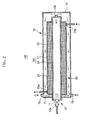
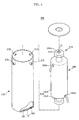
- Figure 1 is an assembly drawing of a fuel reforming apparatus constructed as an embodiment according to the principles of the present invention and Figure 2 is a cross-sectional view of the fuel reforming apparatus of Figure 1, when the fuel reforming apparatus is assembled.
- a fuel reforming apparatus 100 is configured to generate a reformed gas containing hydrogen by burning a fuel together with an oxidizing gas to generate thermal energy and performing a reforming reaction of the gaseous fuel using the thermal energy.
- Fuel reforming apparatus 100 is used for a polymer electrolyte membrane fuel cell system that generates electrical energy through an oxidation reaction of the reformed gas and a reduction reaction of an oxidizing gas. Therefore, the reformed gas generated from fuel reforming apparatus 100 is supplied to a stack of the polymer electrolyte membrane fuel cell system.
- the fuel used in fuel reforming apparatus 100 may be a liquid fuel containing hydrogen, such as methanol, ethanol, liquid petroleum gas (LPG), liquid natural gas (LNG) or gasoline, or a gaseous fuel containing hydrogen.
- a liquid fuel containing hydrogen such as methanol, ethanol, liquid petroleum gas (LPG), liquid natural gas (LNG) or gasoline, or a gaseous fuel containing hydrogen.
- oxygen stored in a storage unit or ambient air containing oxygen may be used as the oxidizing gas.
- ambient air containing the oxygen is used as oxidizing gas.
- Fuel reforming apparatus 100 is constructed with a heat source 10 for generating thermal energy by burning the fuel together with atmospheric air and a reforming reaction unit 30 for generating a reformed gas containing hydrogen through a reforming reaction of the fuel using the thermal energy generated by heat source 10.
- Fuel reforming apparatus 100 is also constructed with a main body 50 having a concentric dual-pipe structure. That is, main body 50 includes a first pipe 51 and a second pipe 52 disposed inside first pipe 51.
- First pipe 51 is in this example cylindrical, having opposite ends that are closed and a circular cross sectional area.
- Second pipe 52 is also cylindrical having a cross sectional area smaller than that of first pipe 51 and opposite ends that are closed.
- First and second pipes 51 and 52 are coaxially disposed so that an outer circumference of second pipe 52 is spaced apart from an inner circumference of first pipe 51 by an interval.
- heat source 10 functions to burn the fuel and supply the thermal energy generated by burning the fuel to reforming reaction unit 30.
- Heat source 10 is constructed with a torch 11 connected to a first end of second pipe 52.
- Torch 11 functions to ignite the gaseous fuel together with the air in second pipe 52.
- Torch 11 is constructed with an ignition plug (not shown) for igniting the gaseous fuel and the atmospheric air. Torch 11 is also constructed with a first injection port 13a for injecting the fuel and the atmospheric air into second pipe 52.
- a first discharging port 13b for discharging combustion gas generated during the burning of the fuel and air in second pipe 52 is formed on a second end of second pipe 52.
- reforming reaction unit 30 is constructed by filling the space between the first and second pipes 51 and 52 with a reforming catalyst 31, and accordingly, the reformed gas containing hydrogen is generated through a reforming reaction of the gaseous fuel using reforming catalyst 31.
- Reforming catalyst 31 may contain a pellet-type carrier made from alumina (Al 2 O 3 ), silica (SiO 2 ), or titania (TiO 2 ) and a catalytic material such as copper (Cu), nickel (Ni), or platinum (Pt) that is supported in the pellet-type carrier.
- a pellet-type carrier made from alumina (Al 2 O 3 ), silica (SiO 2 ), or titania (TiO 2 ) and a catalytic material such as copper (Cu), nickel (Ni), or platinum (Pt) that is supported in the pellet-type carrier.
- a third injection port 33a for injecting the fuel into the space between the first and second pipes 51 and 52 is formed on a first end of first pipe 51.
- a second discharging port 33b for discharging the reformed gas generated in the space between first and second pipes 51 and 52 through the reforming reaction between the fuel and reforming catalyst 31 is formed on a second end of first pipe 51.
- Fuel reforming apparatus 100 is constructed with a housing 70 enclosing main body 50.
- Housing 70 allows a relatively high temperature combustion gas discharged through first discharging port 13b of heat source 10 to flow along an outer circumference of reforming reaction unit 30. That is, housing 70 functions to additionally supply the thermal energy of the combustion gas to reforming reaction unit 30.
- housing 70 also functions as a thermal insulation case that can prevent the thermal energy acting on main body 50 from being dissipated to an external side.
- Housing 70 is formed in a cylindrical pipe-shape providing an internal space for receiving main body 50.
- Housing 70 has a first end 76 that is opened and a second end 78 that is closed.
- Housing 70 is constructed with a sealing cap 71 for sealing the opening first end 76.
- sealing cap 71 is formed in a flat donut-shaped disk so that one end of main body 50 received in housing 70 can protrude out of housing 70 through central hole 72 of sealing cap 71.
- Housing 70 is coaxially disposed around first pipe 51 such that an outer circumference of first pipe 51 is spaced apart from an inner circumference of housing 70. That is, the cross section area of housing 70 is greater than that of first pipe 51.
- a flow path 73 is defined between housing 70 and reforming reaction unit 30 along which the combustion gas discharged through first discharging port 13b can flow while contacting the outer circumference of reforming reaction unit 30 .
- housing 70 may be made from a metallic thermally insulating material such as stainless steel, zirconium, or aluminum or a non-metallic thermally insulating material such as ceramic.
- housing 70 is provided near the first end that is open with one or more discharging ports 75 for discharging the combustion gas circulating along flow path 73.
- discharging ports 75 may be formed at a portion near first end of the housing 70 and spaced apart from each at an interval of 90°.
- the fuel and atmospheric air are supplied into second pipe 52 through first injection port 13a of torch 11.
- the thermal energy is supplied to reforming catalyst 31 of reforming reacting unit 30 through the cylindrical wall of the second pipe 52.
- the combustion gas circulates along flow path 73 defined between first pipe 51 and housing 70 while contacting the outer circumference of reforming reaction unit 30.
- the thermal energy of the combustion gas in path 73 is additionally supplied to reforming reaction unit 30.
- reforming reaction unit 30 Since the reforming reaction unit 30 receives the thermal energy of the combustion gas as well as the thermal energy directly supplied from heat source 10, reforming reaction unit 30 can maintain a uniform temperature distribution within a reaction start temperature range required for the reforming reaction throughout the entire region of reforming reaction unit 30.
- the combustion gas circulating along flow path 73 is discharged to the external side through discharging ports 75 of housing 70.
- the fuel is supplied to a space defined between first and second pipes 51 and 52 through third injection port 33a of reforming reaction unit 30. Then, the reforming reaction of the fuel is promoted by reforming catalyst 31 in reforming reaction unit 30, thereby generating the reformed gas.
- the reformed gas is discharged through the second discharging port 33b of reforming reaction unit 30 and then supplied to the stack of the polymer electrolyte membrane fuel cell system. An oxidation reaction of hydrogen contained in the reformed gas and a reduction reaction of the separately supplied atmospheric air are performed in the stack to generate electrical energy.
- FIG 3 is a cross-sectional view of a modified example of the fuel reforming apparatus of Figure 1.
- a fuel reforming apparatus 200 of this modified example is identical to that of the foregoing embodiment of Figure 2 except that a heat source 110 is filled with an oxidizing catalyst 115 in a second pipe 152.
- heat source 110 is configured to generate the thermal energy through an oxidation reaction between oxidizing catalyst 115 and the fuel and atmospheric air. Therefore, in heat source 110, second pipe 152 is provided at a first end with a first injection port 113a through which the fuel and air are injected into second pipe 152. Second pipe 152 is further provided at a second end with a first discharging port 113b through which the combustion gas generated during the burning of the fuel and air by oxidizing catalyst 115 is discharged.
- Oxidizing catalyst 115 may contain a pellet-type carrier made from alumina (Al 2 O 3 ), silica (SiO 2 ), or titania (TiO 2 ) and a catalytic material such as platinum (Pt) or ruthenium (Ru) that is supported on the pellet-type carrier.
- a pellet-type carrier made from alumina (Al 2 O 3 ), silica (SiO 2 ), or titania (TiO 2 ) and a catalytic material such as platinum (Pt) or ruthenium (Ru) that is supported on the pellet-type carrier.
- the fuel and atmospheric air are supplied into second pipe 152 through first injection port 113a of heat source 110. Then, the thermal energy is generated in heat source 110 through the oxidation reaction of the fuel and atmospheric air by oxidizing catalyst 115. In addition, the combustion gas generated during the burning of the fuel and atmospheric air by oxidizing catalyst 115 is discharged through first discharging port 113b of heat source 110.
- Figure 4 is an assembly drawing of a fuel reforming apparatus according to another embodiment of the present invention and Figure 5 is a sectional view of the fuel reforming apparatus of Figure 4, when the fuel reforming apparatus is assembled.
- a housing 370 serves as a heat insulation case for preventing the thermal energy applied from a heat source 310 to a main body 350 from being dissipated to the external side.
- housing 370 will be referred to as "main thermal insulation member.”
- the combustion gas generated during the burning of the fuel in heat source 310 is discharged through a first discharging port 313b of heat source 310 and then circulated along a flow path 373 defined between first pipe 351 and main thermal insulation member 370.
- an auxiliary thermal insulation member 390 is provided on portion A of main auxiliary insulation member 370.
- Auxiliary thermal insulation member 390 prevents the thermal energy of the combustion gas from being locally discharged through portion A.
- Auxiliary thermal insulation member 390 is constructed with a thermal insulation plate 391 attached on an inner wall of the end (portion A) of main thermal insulation member 370.
- Thermal insulation plate 391 is formed in a shape corresponding to that of the portion A and made from a material identical to that of main thermal insulation member 370.
- thermal insulation plate 391 is formed in a disk-shape corresponding to a shape of the end of main thermal insulation member 370.
- thermal insulation plate 391 may be installed on portion A.
- thermal insulation plate 391 is attached on portion A through a welding process.
- thermal insulation plate 391 may be attached on portion A by an adhesive substance.
- the fuel and atmospheric air are supplied into second pipe 352 through first injection port 313a of torch 311.
- the relatively high temperature combustion gas generated by the burning of the fuel and atmospheric air in second pipe 352 is discharged through first discharging port 313b of heat source 310.
- the combustion gas circulates along the flow path 373 defined between first pipe 351 and main insulation member 370 while contacting the outer circumference of reforming reaction unit 330.
- the thermal energy of the combustion gas is additionally applied to reforming reaction unit 330.
- reforming reaction unit 330 receives the thermal energy of the combustion gas as well as the thermal energy directly supplied from heat source 310, reforming reaction unit 330 can maintain a uniform temperature distribution within a reaction start temperature range required for the reforming reaction throughout the entire region of reforming reaction unit 330.
- the combustion gas circulating along flow path 373 is discharged to the external side through discharging port 375 of main thermal insulation member 370.
- the thermal energy applied to reforming reaction unit 330 and flow path 373 by heat source 310 is inhibited from passing out of the reformer by the thermal insulation provided by the main thermal insulation member 370.
- thermal insulation plate 391 is installed on portion A of main thermal insulation member 370, dissipation of the thermal energy of the combustion gas locally acting on portion A of main thermal insulation member 370 through the portion A can be substantially prevented by thermal insulation plate 391.
- the combustion gas maintains its thermal energy and circulates along flow path 373 defined between first pipe 351 and main thermal insulation member 370, thereby additionally applying the thermal energy to reforming reaction unit 330.
- the fuel is supplied to a space defined between first and second pipes 351 and 352 through first injection port 333a of reforming reaction unit 330. Then, the reforming reaction of the fuel is promoted by reforming catalyst 31 in reforming reaction unit 30, thereby generating reformed gas containing hydrogen.
- the reformed gas is discharged through second discharging port 333b of reforming reaction unit 330 and then supplied to the stack of the polymer electrolyte membrane fuel cell system.
- An oxidation reaction of hydrogen contained in the reformed gas and a reduction reaction of the separately supplied atmospheric air are performed in the stack to generate predetermined electrical energy.
- FIG. 6 is a cross-sectional view of a modified example of the fuel reforming apparatus of Figure 5.
- an auxiliary thermal insulation member 490 is constructed with a thermally insulating material 491 that is buried near a portion A of a main thermal insulation member 470.
- a receiving space 471 is provided near portion A of main thermal insulation member 470 and filled with the thermally insulating material.
- Receiving space 471 is defined between an inner wall of portion A and a barrier 473 spaced apart from the inner wall of portion A.
- the thermally insulating material may be a glass fiber.
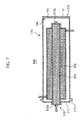
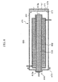
- Figures 7 and 8 are cross-sectional views of other modified examples of the fuel reforming apparatus of Figure 5.
- an oxidizing catalyst 515, 615 fills a second pipe 552, 652 of a heat source 510, 610.
- Heat source 510, 610 is configured to generate the thermal energy through the oxidation reaction of the fuel and atmospheric air by the oxidizing catalyst 515, 615.
- a first injection port 513a, 613a for injecting the fuel and atmospheric air into second pipe 552, 652 is formed on a first end of second pipe 552, 652.
- a first discharging port 513b, 613b for discharging the combustion gas generated during the burning of the fuel and atmospheric air by oxidizing catalyst 515 and 615 is formed on a second end of second pipe 552, 652.
- Oxidizing catalyst 515, 615 may contain a pellet-type carrier made from alumina (Al 2 O 3 ), silica (SiO 2 ), or titania (TiO 2 ) and a catalytic material such as platinum (Pt) or ruthenium (Ru) that is supported in the pellet-type carrier.
- a pellet-type carrier made from alumina (Al 2 O 3 ), silica (SiO 2 ), or titania (TiO 2 ) and a catalytic material such as platinum (Pt) or ruthenium (Ru) that is supported in the pellet-type carrier.
- auxiliary thermal insulation member 590 in fuel reforming apparatus 500 is constructed with a thermal insulation plate 591 attached on an inner wall of the end wall 578 (portion A) of main thermal insulation member 570.
- Thermal insulation plate 591 is formed in a shape corresponding to that of portion A and made from a material identical to that of main thermal insulation member 570.
- thermal insulation plate 591 is formed in a disk-shape corresponding to a shape of the end of main thermal insulation member 570.
- auxiliary thermal insulation member 690 in fuel reforming apparatus 600 is constructed with a thermally insulating material 691 that is buried near a portion A of main thermal insulation member 670.
- a receiving space 671 is provided near portion A of main thermal insulation member 670 and filled with the thermally insulating material.
- Receiving space 671 is defined between an inner wall of portion A and a barrier 673 spaced apart from the inner wall of portion A.
- the thermally insulating material may be a glass fiber.
- the fuel reforming apparatus further includes the housing enclosing the main body, the housing allows a relatively high temperature combustion gas discharged through the first discharging port of the heat source to flow along an outer circumference of the reforming reaction unit. As a result, the thermal energy of the combustion gas is additionally applied to the reforming reaction unit.
- the reforming reaction unit receives the thermal energy of the combustion gas as well as the thermal energy directly supplied from the heat source, it can maintain a uniform temperature distribution within a reaction start temperature range required for the reforming reaction throughout the entire region. As a result, the thermal efficiency and performance efficiency of the fuel cell system can be further improved.
- the auxiliary thermal insulation member is additionally installed on a local portion of the main thermal insulation member, which locally contacts the combustion gas discharged from the heat source, the dissipation of the thermal energy to the external side through the local portion of the main thermal insulation member can be prevented, thereby reducing the thermal energy loss and preventing the main thermal insulation member from being locally damaged.
Abstract
Description
- The present invention relates to a fuel reforming apparatus for a fuel cell system.
- As is well known, a fuel cell is a system for generating electric energy using a fuel. In the fuel cell, a polymer electrolyte membrane fuel cell has an excellent output characteristic, a low operating temperature, and fast starting and response characteristics. Therefore, the polymer electrolyte fuel cell advantageously has a wide range of applications including a mobile power source for vehicles, a distributed power source for home or buildings, and a small-sized power source for electronic apparatuses.
- The fuel cell system employing the polymer electrolyte membrane fuel cell is constructed with a fuel cell main body (hereinafter, referred to as "stack"), a fuel reformer which reforms the fuel to generate a reformed gas containing hydrogen and supplies the reformed gas to the fuel cell main body, and an oxidizing gas supply unit which supplies an oxidizing gas to the stack.
- Therefore, the polymer electrolyte membrane fuel cell system generates electric energy through an electro-chemical reaction between the reformed gas and oxidizing gas that are supplied to the stack. The fuel reformer may be constructed with a heat source that generates thermal energy by directly burning the fuel and a reforming reaction unit that generates the reformed gas through a reforming reaction of the fuel using the thermal energy.
- In the contemporary fuel reformer, a relatively high temperature combustion gas, which is generated while the fuel is burned in the heat source, is exhausted as it is. This causes the loss of the heat energy of the combustion gas and thus increases the startup time. As a result, the thermal efficiency and performance efficiency of the system are deteriorated.
- In addition, since the high temperature combustion gas exhausted through an outlet of the heat source contacts locally a portion of the housing of the fuel reformer, which corresponds to the outlet of the heat source, the housing may be damaged or the thermal energy of the combustion gas may be discharged to an external space through the local portion of the housing, thereby causing the thermal insulation performance to deteriorate.
- As described above, in the contemporary fuel reformer, the thermal energy generated from the heat source is discharged through the local portion of the housing and thus the startup time increases. This causes a deterioration of thermal efficiency and performance efficiency of the fuel system.
- It is therefore an object of the present invention to provide an improved fuel reforming apparatus.
- In one aspect the present invention provides a fuel reforming apparatus that is configured to additionally supply thermal energy of the combustion gas to a reforming reaction unit.
- In another aspect the present invention provides a fuel reforming apparatus that is configured to improve a thermal insulation performance for thermal energy generated from a heat source.
- In an exemplary embodiment of the present invention, a fuel reforming apparatus is constructed with a main body including a first pipe and a second pipe disposed inside the first pipe, a heat source installed in the second pipe and adapted to generate thermal energy by burning fuel in the second pipe, a reforming reaction unit formed by filling a reforming catalyst in a space defined between the first and second pipes and adapted to generate a reformed gas containing hydrogen through a reforming reaction of the fuel, and a housing enclosing the main body and allowing a combustion gas generated from the heat source to flow along an outer circumference of the reforming reaction unit.
- A flow path along which the combustion gas flows may be formed between the housing and the first pipe.
- The housing may be provided with at least one discharging port for discharging the combustion gas flowing along the flow path.
- The housing may be made from a thermally insulating material.
- The heat source may be provided with a torch connected to a first end of the second pipe and igniting and burning the fuel together with the air.
- The heat source may be provided with a first injection port formed on the torch to inject the fuel and air into the second pipe and a first discharging port formed on a second end of the second pipe to discharge the combustion gas to a space defined between the first pipe and the housing.
- The heat source may be configured to generate the thermal energy through an oxidation reaction of the fuel and air by an oxidizing catalyst filled in the second pipe.
- The heat source may be provided with a first injection port formed on a first end of the second pipe to inject the fuel and air into the second pipe and a first discharging port formed on a second end of the second pipe to discharge the combustion gas to a space defined between the first pipe and the housing. The reforming reaction unit may be provided with a second injection port formed on a first end of the first pipe to inject the fuel into a space defined between the first and second pipes and a second discharging port formed on a second end of the first pipe to discharge the reformed gas.
- In another exemplary embodiment of the present invention, a fuel reforming apparatus is constructed with a heat source adapted to generate thermal energy by burning a fuel, a reforming reaction unit adapted to generate a reformed gas containing hydrogen through a reforming reaction of the fuel using the thermal energy, a main thermal insulation member enclosing the heat source and reforming reaction unit to prevent the thermal energy generated from the heat source from being dissipated to an external side, and an auxiliary thermal insulation member installed on a local portion of the main thermal insulation member, which locally contacts a combustion gas generated from the heat source.
- The main thermal insulation member may be provided in the form of a housing.
- The auxiliary thermal insulation member may be provided with at least one thermal insulation plate attached on the local portion of the main thermal insulation member.
- The main thermal insulation member and the auxiliary thermal insulation member may be made from a material selected from the group consisting of stainless steel, zirconium, aluminium, and ceramic.
- The main thermal insulation member may be provided with a receiving portion formed near the local portion and the auxiliary thermal insulation member is made from a thermally insulating material filled in the receiving portion.
- The thermally insulating material may be a glass fiber.
- In still another exemplary embodiment of the present invention, a fuel reforming apparatus is constructed with a main body comprising a first pipe and a second pipe disposed in the first pipe, a heat source installed in the second pipe and adapted to generate thermal energy by burning fuel in the second pipe, a reforming reaction unit formed by filling a reforming catalyst in a space defined between the first and second pipes and adapted to generate a reformed gas containing hydrogen through a reforming reaction of the fuel, a main thermal insulation member enclosing the main body to allow a combustion gas generated from the heat source to flow along an outer circumference of the reforming reaction unit, and an auxiliary thermal insulation member installed on a local portion of the main thermal insulation member, which contacts locally a combustion gas generated from the heat source.
- The main thermal insulation member may be provided in the form of a housing having a cross section area greater than that of the first pipe and a flow path is formed between the first pipe and the housing.
- The auxiliary thermal insulation member may be provided with at least one thermal insulation plate attached on the local portion of the main thermal insulation member.
- The main thermal insulation member may be provided with a receiving portion formed near the local portion and the auxiliary thermal insulation member is made from a thermally insulating material filled in the receiving portion.
- The heat source may be provided with a torch connected to a first end of the second pipe and igniting and burning the fuel together with the air in the second pipe, a first injection port formed on the torch to inject the fuel and air into the second pipe, and a first discharging port formed on a second end of the second pipe to discharge the combustion gas to a space defined between the first pipe and the housing.
- The auxiliary thermal insulation member may be provided with at least one thermal insulation plate attached on an inner wall of the main thermal insulation member, which corresponds to the first discharging port.
- The main thermal insulation member may be provided with a receiving portion formed to correspond to the first discharging port and the auxiliary thermal insulation member is made from a thermally insulating material filling the receiving portion.
- The heat source may be configured to generate the thermal energy through an oxidation reaction of the fuel and air by an oxidizing catalyst filling in the second pipe.
- The heat source may be provided with a first injection port formed on a first end of the second pipe to inject the fuel and air into the second pipe and a first discharging port formed on a second end of the second pipe to discharge the combustion gas to a space defined between the first pipe and the housing. The reforming reaction unit be provided with a second injection port formed on a first end of the first pipe to inject the fuel into a space defined between the first and second pipes and a second discharging port formed on a second end of the first pipe to discharge the reformed gas.
- A more complete appreciation of the invention, and many of the attendant advantages thereof, will be readily apparent as the same becomes better understood by reference to the following detailed description when considered in conjunction with the accompanying drawings in which like reference symbols indicate the same or similar components, wherein:
- Figure 1 is an assembly drawing of a fuel reforming apparatus constructed as an embodiment in accordance with the present invention;
- Figure 2 is a cross-sectional view of the fuel reforming apparatus of Figure 1, when the fuel reforming apparatus is assembled;
- Figure 3 is a cross-sectional view of a modified example of the fuel reforming apparatus of Figure 1;
- Figure 4 is an assembly drawing of a fuel reforming apparatus constructed as another embodiment in accordance with the present invention;
- Figure 5 is a cross-sectional view of the fuel reforming apparatus of Figure 4, when the fuel reforming apparatus is assembled;
- Figure 6 is a cross-sectional view of a modified example of the fuel reforming apparatus of Figure 5;
- Figure 7 is a cross-sectional view of another modified example of the fuel reforming apparatus of Figure 5; and
- Figure 8 is a cross-sectional view of another modified example of the fuel reforming apparatus of Figure 5.
- The present invention will now be described more fully with reference to the accompanying drawings, in which exemplary embodiments of the invention are shown. The invention may, however, be embodied in many different forms and should not be construed as being limited to the embodiments set forth herein. Wherever possible, the same reference numbers will be used throughout the drawings to refer to the same or like parts.
- Figure 1 is an assembly drawing of a fuel reforming apparatus constructed as an embodiment according to the principles of the present invention and Figure 2 is a cross-sectional view of the fuel reforming apparatus of Figure 1, when the fuel reforming apparatus is assembled.
- Referring to Figures 1 and 2, a
fuel reforming apparatus 100 is configured to generate a reformed gas containing hydrogen by burning a fuel together with an oxidizing gas to generate thermal energy and performing a reforming reaction of the gaseous fuel using the thermal energy. -
Fuel reforming apparatus 100 is used for a polymer electrolyte membrane fuel cell system that generates electrical energy through an oxidation reaction of the reformed gas and a reduction reaction of an oxidizing gas. Therefore, the reformed gas generated fromfuel reforming apparatus 100 is supplied to a stack of the polymer electrolyte membrane fuel cell system. - The fuel used in
fuel reforming apparatus 100 may be a liquid fuel containing hydrogen, such as methanol, ethanol, liquid petroleum gas (LPG), liquid natural gas (LNG) or gasoline, or a gaseous fuel containing hydrogen. - In addition, oxygen stored in a storage unit or ambient air containing oxygen may be used as the oxidizing gas. In the present embodiment, the case where ambient air containing the oxygen is used as oxidizing gas is described.
-
Fuel reforming apparatus 100 is constructed with aheat source 10 for generating thermal energy by burning the fuel together with atmospheric air and a reformingreaction unit 30 for generating a reformed gas containing hydrogen through a reforming reaction of the fuel using the thermal energy generated byheat source 10. -
Fuel reforming apparatus 100 is also constructed with amain body 50 having a concentric dual-pipe structure. That is,main body 50 includes afirst pipe 51 and asecond pipe 52 disposed insidefirst pipe 51. -
First pipe 51 is in this example cylindrical, having opposite ends that are closed and a circular cross sectional area.Second pipe 52 is also cylindrical having a cross sectional area smaller than that offirst pipe 51 and opposite ends that are closed. First andsecond pipes second pipe 52 is spaced apart from an inner circumference offirst pipe 51 by an interval. - In
fuel reforming apparatus 100,heat source 10 functions to burn the fuel and supply the thermal energy generated by burning the fuel to reformingreaction unit 30. Heatsource 10 is constructed with atorch 11 connected to a first end ofsecond pipe 52.Torch 11 functions to ignite the gaseous fuel together with the air insecond pipe 52. -
Torch 11 is constructed with an ignition plug (not shown) for igniting the gaseous fuel and the atmospheric air.Torch 11 is also constructed with afirst injection port 13a for injecting the fuel and the atmospheric air intosecond pipe 52. - In addition, in
heat source 10, a first dischargingport 13b for discharging combustion gas generated during the burning of the fuel and air insecond pipe 52 is formed on a second end ofsecond pipe 52. - In the present embodiment, reforming
reaction unit 30 is constructed by filling the space between the first andsecond pipes catalyst 31, and accordingly, the reformed gas containing hydrogen is generated through a reforming reaction of the gaseous fuel using reformingcatalyst 31. - Reforming
catalyst 31 may contain a pellet-type carrier made from alumina (Al2O3), silica (SiO2), or titania (TiO2) and a catalytic material such as copper (Cu), nickel (Ni), or platinum (Pt) that is supported in the pellet-type carrier. - In addition, a
third injection port 33a for injecting the fuel into the space between the first andsecond pipes first pipe 51. A second dischargingport 33b for discharging the reformed gas generated in the space between first andsecond pipes catalyst 31 is formed on a second end offirst pipe 51. -
Fuel reforming apparatus 100 is constructed with ahousing 70 enclosingmain body 50.Housing 70 allows a relatively high temperature combustion gas discharged through first dischargingport 13b ofheat source 10 to flow along an outer circumference of reformingreaction unit 30. That is,housing 70 functions to additionally supply the thermal energy of the combustion gas to reformingreaction unit 30. - In addition,
housing 70 also functions as a thermal insulation case that can prevent the thermal energy acting onmain body 50 from being dissipated to an external side. -
Housing 70 is formed in a cylindrical pipe-shape providing an internal space for receivingmain body 50.Housing 70 has afirst end 76 that is opened and asecond end 78 that is closed.Housing 70 is constructed with a sealingcap 71 for sealing the openingfirst end 76. At this point, sealingcap 71 is formed in a flat donut-shaped disk so that one end ofmain body 50 received inhousing 70 can protrude out ofhousing 70 throughcentral hole 72 of sealingcap 71. -
Housing 70 is coaxially disposed aroundfirst pipe 51 such that an outer circumference offirst pipe 51 is spaced apart from an inner circumference ofhousing 70. That is, the cross section area ofhousing 70 is greater than that offirst pipe 51. - Therefore, a
flow path 73 is defined betweenhousing 70 and reformingreaction unit 30 along which the combustion gas discharged through first dischargingport 13b can flow while contacting the outer circumference of reformingreaction unit 30 . - In order to prevent the thermal energy, which is generated by
heat source 10 and acts onmain body 50, from being dissipated throughhousing 70,housing 70 may be made from a metallic thermally insulating material such as stainless steel, zirconium, or aluminum or a non-metallic thermally insulating material such as ceramic. - Furthermore,
housing 70 is provided near the first end that is open with one or more dischargingports 75 for discharging the combustion gas circulating alongflow path 73. Four dischargingports 75 may be formed at a portion near first end of thehousing 70 and spaced apart from each at an interval of 90°. - The operation of the above-described fuel reforming apparatus will now be described in detail.
- The fuel and atmospheric air are supplied into
second pipe 52 throughfirst injection port 13a oftorch 11. - In this state, when the ignition plug (not shown) is operated, the fuel and air sprayed into
second pipe 52 is ignited by the ignition plug in theheat source 10. Then, the fuel and air are burned to generate thermal energy insecond pipe 52. - Since the reforming
reaction unit 30 is formed externally of theheat source 10, the thermal energy is supplied to reformingcatalyst 31 of reforming reactingunit 30 through the cylindrical wall of thesecond pipe 52. - During the above-procedure, the relatively high temperature combustion gas generated by the burning of the fuel and air in
second pipe 52 is discharged through first dischargingport 13b ofheat source 10. - As indicated by arrows in Figure 2, the combustion gas circulates along
flow path 73 defined betweenfirst pipe 51 andhousing 70 while contacting the outer circumference of reformingreaction unit 30. As a result, the thermal energy of the combustion gas inpath 73 is additionally supplied to reformingreaction unit 30. - Since the reforming
reaction unit 30 receives the thermal energy of the combustion gas as well as the thermal energy directly supplied fromheat source 10, reformingreaction unit 30 can maintain a uniform temperature distribution within a reaction start temperature range required for the reforming reaction throughout the entire region of reformingreaction unit 30. The combustion gas circulating alongflow path 73 is discharged to the external side through dischargingports 75 ofhousing 70. - In this state, the fuel is supplied to a space defined between first and
second pipes third injection port 33a of reformingreaction unit 30. Then, the reforming reaction of the fuel is promoted by reformingcatalyst 31 in reformingreaction unit 30, thereby generating the reformed gas. The reformed gas is discharged through the second dischargingport 33b of reformingreaction unit 30 and then supplied to the stack of the polymer electrolyte membrane fuel cell system. An oxidation reaction of hydrogen contained in the reformed gas and a reduction reaction of the separately supplied atmospheric air are performed in the stack to generate electrical energy. - Figure 3 is a cross-sectional view of a modified example of the fuel reforming apparatus of Figure 1. Referring to Figure 3, a
fuel reforming apparatus 200 of this modified example is identical to that of the foregoing embodiment of Figure 2 except that aheat source 110 is filled with an oxidizingcatalyst 115 in asecond pipe 152. - That is,
heat source 110 is configured to generate the thermal energy through an oxidation reaction between oxidizingcatalyst 115 and the fuel and atmospheric air. Therefore, inheat source 110,second pipe 152 is provided at a first end with afirst injection port 113a through which the fuel and air are injected intosecond pipe 152.Second pipe 152 is further provided at a second end with a first dischargingport 113b through which the combustion gas generated during the burning of the fuel and air by oxidizingcatalyst 115 is discharged. - Oxidizing
catalyst 115 may contain a pellet-type carrier made from alumina (Al2O3), silica (SiO2), or titania (TiO2) and a catalytic material such as platinum (Pt) or ruthenium (Ru) that is supported on the pellet-type carrier. - When
fuel reforming apparatus 200 is operated, the fuel and atmospheric air are supplied intosecond pipe 152 throughfirst injection port 113a ofheat source 110. Then, the thermal energy is generated inheat source 110 through the oxidation reaction of the fuel and atmospheric air by oxidizingcatalyst 115. In addition, the combustion gas generated during the burning of the fuel and atmospheric air by oxidizingcatalyst 115 is discharged through first dischargingport 113b ofheat source 110. - Since other parts of
fuel reforming apparatus 200 according to this modified example and the operation thereof are identical to those of the foregoing embodiment of Figure 2, the detailed description offuel reforming apparatus 200 will be omitted herein. - Figure 4 is an assembly drawing of a fuel reforming apparatus according to another embodiment of the present invention and Figure 5 is a sectional view of the fuel reforming apparatus of Figure 4, when the fuel reforming apparatus is assembled.
- Since a basic structure of the fuel reforming apparatus of this embodiment is identical to that of the foregoing embodiment of Figures 1 and 2, only the different structure and operation from those of the foregoing embodiment will be described in the following description.
- In a
fuel reforming apparatus 300 of this embodiment, ahousing 370 serves as a heat insulation case for preventing the thermal energy applied from aheat source 310 to amain body 350 from being dissipated to the external side. For convenience,housing 370 will be referred to as "main thermal insulation member." - The combustion gas generated during the burning of the fuel in
heat source 310 is discharged through a first dischargingport 313b ofheat source 310 and then circulated along aflow path 373 defined betweenfirst pipe 351 and mainthermal insulation member 370. - During the above procedure, since the combustion gas discharged through first discharging
port 313b ofheat source 310 locally contacts an end (a portion A in Figures 4 and 5) of mainthermal insulation member 370, which corresponds to first dischargingport 313b, a temperature of the portion A increases locally and thus the thermal energy is dissipated through the portion A. As a result, the overall thermal insulation performance offuel reforming apparatus 300 deteriorates. - Therefore, in this embodiment, an auxiliary
thermal insulation member 390 is provided on portion A of mainauxiliary insulation member 370. Auxiliarythermal insulation member 390 prevents the thermal energy of the combustion gas from being locally discharged through portion A. - Auxiliary
thermal insulation member 390 is constructed with athermal insulation plate 391 attached on an inner wall of the end (portion A) of mainthermal insulation member 370.Thermal insulation plate 391 is formed in a shape corresponding to that of the portion A and made from a material identical to that of mainthermal insulation member 370. - That is, when main
thermal insulation member 370 is formed in a cylindrical shape having a circular section,thermal insulation plate 391 is formed in a disk-shape corresponding to a shape of the end of mainthermal insulation member 370. - Referring to Figures 4 and 5, although only one
thermal insulation plate 391 is provided on portion A, the present invention is not limited thereto. For example, a plurality ofthermal insulation plates 391 may be installed on portion A. - When main
thermal insulation member 370 is made from a metallic thermally insulating material,thermal insulation plate 391 is attached on portion A through a welding process. When mainthermal insulation member 370 is made from a non-metallic thermally insulating material,thermal insulation plate 391 may be attached on portion A by an adhesive substance. - The operation of
fuel reforming apparatus 300 constructed as this embodiment will now be described in detail. - First, the fuel and atmospheric air are supplied into
second pipe 352 throughfirst injection port 313a oftorch 311. - In this state, when the ignition plug (not shown) is operated, the fuel and atmospheric air are sprayed into
second pipe 352 and ignited by the ignition plug inheat source 310. Then, the fuel and atmospheric air are burned to generate the thermal energy insecond pipe 352. Since reformingreaction unit 330 is formed externally ofheat source 310, the thermal energy is supplied to reformingcatalyst 331 of reforming reactingunit 330 through the cylindrical wall ofsecond pipe 352. - During the above-procedure, the relatively high temperature combustion gas generated by the burning of the fuel and atmospheric air in
second pipe 352 is discharged through first dischargingport 313b ofheat source 310. - As indicated by arrows in Figure 5, the combustion gas circulates along the
flow path 373 defined betweenfirst pipe 351 andmain insulation member 370 while contacting the outer circumference of reformingreaction unit 330. As a result, the thermal energy of the combustion gas is additionally applied to reformingreaction unit 330. - Accordingly, since reforming
reaction unit 330 receives the thermal energy of the combustion gas as well as the thermal energy directly supplied fromheat source 310, reformingreaction unit 330 can maintain a uniform temperature distribution within a reaction start temperature range required for the reforming reaction throughout the entire region of reformingreaction unit 330. The combustion gas circulating alongflow path 373 is discharged to the external side through dischargingport 375 of mainthermal insulation member 370. - The thermal energy applied to reforming
reaction unit 330 and flowpath 373 byheat source 310 is inhibited from passing out of the reformer by the thermal insulation provided by the mainthermal insulation member 370. - During the above procedure, the high temperature combustion gas generated from
heat source 310 is locally directed to the end (portion A) of mainthermal insulation member 370 through first dischargingport 313b. At this point, sincethermal insulation plate 391 is installed on portion A of mainthermal insulation member 370, dissipation of the thermal energy of the combustion gas locally acting on portion A of mainthermal insulation member 370 through the portion A can be substantially prevented bythermal insulation plate 391. - Therefore, the combustion gas maintains its thermal energy and circulates along
flow path 373 defined betweenfirst pipe 351 and mainthermal insulation member 370, thereby additionally applying the thermal energy to reformingreaction unit 330. - In this state, the fuel is supplied to a space defined between first and
second pipes first injection port 333a of reformingreaction unit 330. Then, the reforming reaction of the fuel is promoted by reformingcatalyst 31 in reformingreaction unit 30, thereby generating reformed gas containing hydrogen. - The reformed gas is discharged through second discharging
port 333b of reformingreaction unit 330 and then supplied to the stack of the polymer electrolyte membrane fuel cell system. An oxidation reaction of hydrogen contained in the reformed gas and a reduction reaction of the separately supplied atmospheric air are performed in the stack to generate predetermined electrical energy. - Figure 6 is a cross-sectional view of a modified example of the fuel reforming apparatus of Figure 5. Referring to Figure 6, in a
fuel reforming apparatus 400 according to this modified example, an auxiliarythermal insulation member 490 is constructed with a thermally insulatingmaterial 491 that is buried near a portion A of a mainthermal insulation member 470. - That is, a receiving
space 471 is provided near portion A of mainthermal insulation member 470 and filled with the thermally insulating material. Receivingspace 471 is defined between an inner wall of portion A and abarrier 473 spaced apart from the inner wall of portion A. The thermally insulating material may be a glass fiber. - Since other parts of
fuel reforming apparatus 400 according to this modified example and the operation thereof are identical to those of the foregoing embodiment of Figures 4 and 5, the detailed description thereof will be omitted herein. - Figures 7 and 8 are cross-sectional views of other modified examples of the fuel reforming apparatus of Figure 5.
- Referring to Figures 7 and 8, in a
fuel reforming apparatus catalyst second pipe heat source source catalyst - In
heat source first injection port second pipe second pipe port catalyst second pipe - Oxidizing
catalyst - Therefore, when
fuel reforming apparatus second pipe first injection port heat source heat source catalyst catalyst port heat source - Referring to Figure 7, auxiliary
thermal insulation member 590 infuel reforming apparatus 500 is constructed with athermal insulation plate 591 attached on an inner wall of the end wall 578 (portion A) of mainthermal insulation member 570.Thermal insulation plate 591 is formed in a shape corresponding to that of portion A and made from a material identical to that of mainthermal insulation member 570. - That is, when main
thermal insulation member 570 is formed in a cylindrical shape having a circular section,thermal insulation plate 591 is formed in a disk-shape corresponding to a shape of the end of mainthermal insulation member 570. - Referring to Figure 8, auxiliary
thermal insulation member 690 infuel reforming apparatus 600 is constructed with a thermally insulating material 691 that is buried near a portion A of mainthermal insulation member 670. - That is, a receiving
space 671 is provided near portion A of mainthermal insulation member 670 and filled with the thermally insulating material. Receivingspace 671 is defined between an inner wall of portion A and abarrier 673 spaced apart from the inner wall of portion A. The thermally insulating material may be a glass fiber. - Since other parts of
fuel reforming apparatus - According to the present invention, since the fuel reforming apparatus further includes the housing enclosing the main body, the housing allows a relatively high temperature combustion gas discharged through the first discharging port of the heat source to flow along an outer circumference of the reforming reaction unit. As a result, the thermal energy of the combustion gas is additionally applied to the reforming reaction unit.
- Accordingly, since the reforming reaction unit receives the thermal energy of the combustion gas as well as the thermal energy directly supplied from the heat source, it can maintain a uniform temperature distribution within a reaction start temperature range required for the reforming reaction throughout the entire region. As a result, the thermal efficiency and performance efficiency of the fuel cell system can be further improved.
- Furthermore, since the auxiliary thermal insulation member is additionally installed on a local portion of the main thermal insulation member, which locally contacts the combustion gas discharged from the heat source, the dissipation of the thermal energy to the external side through the local portion of the main thermal insulation member can be prevented, thereby reducing the thermal energy loss and preventing the main thermal insulation member from being locally damaged.
- Although exemplary embodiments of the present invention have been described in detail hereinabove, it should be clearly understood that many variations and/or modifications of the basic inventive concept taught herein still fall within the scope of the present invention, as defined by the appended claims.
Claims (15)
- A fuel reforming apparatus, comprising:a main body comprising a first pipe and a second pipe disposed inside the first pipe;a heat source installed in the second pipe and adapted to generate thermal energy by consuming fuel and producing a heated effluent gas in the second pipe;a reforming reaction unit comprising a space between the first and second pipes that contains a reforming catalyst, said reforming reaction unit being adapted to be heated by the heat source and generate a reformed gas containing hydrogen through a reforming catalytic reaction of the fuel; anda housing encasing the main body such as to direct the effluent gas generated from the heat source to flow along and heat an outer circumference of the reforming reaction unit.
- The fuel reforming apparatus of claim 1, including a flow path along which the effluent gas flows between the housing and the first pipe.
- The fuel reforming apparatus of claim 2, including at least one discharging port in the housing for discharging the effluent gas flowing along the flow path.
- The fuel reforming apparatus of claim 2 or 3, wherein the housing is made at least in part from a thermally insulating material.
- The fuel reforming apparatus of any preceding claim, wherein the heat source comprises a torch connected to a first end of the second pipe for burning the fuel together with air.
- The fuel reforming apparatus of claim 5, including a first injection port formed on the torch to inject the fuel and air into the second pipe; and
a first discharging port formed on a second end of the second pipe to discharge the combustion gas to a space defined between the first pipe and the housing. - The fuel reforming apparatus of any one of claims 1 to 4, wherein the heat source is configured to generate the thermal energy through an oxidation reaction of the fuel and air utilising an oxidizing catalyst in the second pipe.
- The fuel reforming apparatus of claim 7, including
a first injection port formed on a first end of the second pipe to inject the fuel and air into the second pipe; and
a first discharging port formed on a second end of the second pipe to discharge the combustion gas to a space defined between the first pipe and the housing. - The fuel reforming apparatus of any preceding claim, including a second injection port formed on a first end of the first pipe to inject the fuel into a space defined between the first and second pipes and a second discharging port formed on a second end of the first pipe to discharge the reformed gas.
- A fuel reforming apparatus, comprising:a heat source adapted to generate thermal energy by consuming a fuel;a reforming reaction unit adapted to generate a reformed gas containing hydrogen through a reforming reaction of the fuel using the thermal energy;a main thermal insulation member enclosing the heat source and reforming reaction unit to prevent the thermal energy generated from the heat source from being dissipated externally; andan auxiliary thermal insulation member installed on a local portion of the main thermal insulation member, which contacts locally a combustion gas generated from the heat source.
- A fuel reforming apparatus as claimed in any one of claims 1 to 9, including a main thermal insulation member that provides said housing encasing the main body; and
an auxiliary thermal insulation member installed on a local portion of the main thermal insulation member, which contacts locally a combustion gas generated from the heat source. - The fuel reforming apparatus of claim 10 or 11, wherein the auxiliary thermal insulation member comprises at least one thermal insulation plate attached to the local portion of the main thermal insulation member.
- The fuel reforming apparatus of claim 10, 11 or 12, wherein the main thermal insulation member comprises a receiving portion formed near the local portion and the auxiliary thermal insulation member is made from a thermally insulating material filled in the receiving portion.
- The fuel reforming apparatus of claim 13, wherein the thermally insulating material is a glass fiber.
- The fuel reforming apparatus of any one of claims 10 to 14, wherein the main thermal insulation member and the auxiliary thermal insulation member are made of stainless steel, zirconium, aluminium or ceramic material.
Applications Claiming Priority (2)
| Application Number | Priority Date | Filing Date | Title |
|---|---|---|---|
| KR1020050089817A KR101265198B1 (en) | 2005-09-27 | 2005-09-27 | Apparatus for reforming fuel |
| KR1020050098516A KR20070042657A (en) | 2005-10-19 | 2005-10-19 | Apparatus for reforming fuel |
Publications (2)
| Publication Number | Publication Date |
|---|---|
| EP1767265A2 true EP1767265A2 (en) | 2007-03-28 |
| EP1767265A3 EP1767265A3 (en) | 2007-07-25 |
Family
ID=37605799
Family Applications (1)
| Application Number | Title | Priority Date | Filing Date |
|---|---|---|---|
| EP06121363A Withdrawn EP1767265A3 (en) | 2005-09-27 | 2006-09-27 | Fuel reforming apparatus heated by a burner |
Country Status (3)
| Country | Link |
|---|---|
| US (1) | US7662350B2 (en) |
| EP (1) | EP1767265A3 (en) |
| JP (1) | JP2007091584A (en) |
Cited By (6)
| Publication number | Priority date | Publication date | Assignee | Title |
|---|---|---|---|---|
| GR1006128B (en) * | 2007-05-25 | 2008-11-03 | . | Higly thermally integrated reformer for hydrogen production. |
| EP2354088A1 (en) * | 2010-02-09 | 2011-08-10 | SK Innovation Co. Ltd. | Hydrogen generator using steam-reforming reaction |
| WO2013117948A1 (en) * | 2012-02-06 | 2013-08-15 | Helbio Societé Anonyme Hydrogen And Energy Production Systems | Heat integrated reformer with catalytic combustion for hydrogen production |
| US10960372B2 (en) | 2012-03-08 | 2021-03-30 | Helbio S.A. | Catalytically heated fuel processor with replaceable structured supports bearing catalyst for fuel cell |
| CN112968198A (en) * | 2021-02-25 | 2021-06-15 | 福州大学 | High-temperature solid oxide electrochemical reaction device |
| US11607657B2 (en) | 2012-02-06 | 2023-03-21 | Helbio S.A. | Heat integrated reformer with catalytic combustion for hydrogen production |
Families Citing this family (4)
| Publication number | Priority date | Publication date | Assignee | Title |
|---|---|---|---|---|
| US8394154B2 (en) * | 2007-12-28 | 2013-03-12 | Texaco Inc. | Counter-current oxidation and steam methane reforming process and reactor therefor |
| KR101001395B1 (en) * | 2009-03-03 | 2010-12-14 | 삼성에스디아이 주식회사 | Fuel Reformer |
| JP5163549B2 (en) * | 2009-03-10 | 2013-03-13 | 株式会社富士通ゼネラル | Inter-refrigerant heat exchanger and refrigerant circuit using the same |
| US10139167B1 (en) * | 2018-05-17 | 2018-11-27 | Michael W. Courson | Heat exchanger |
Citations (10)
| Publication number | Priority date | Publication date | Assignee | Title |
|---|---|---|---|---|
| US5032365A (en) * | 1988-06-14 | 1991-07-16 | Mitsubishi Denki Kabushiki Kaisha | Reaction apparatus |
| WO2000022690A1 (en) * | 1998-10-14 | 2000-04-20 | Northwest Power Systems, Llc | Fuel processing system |
| US20030054213A1 (en) * | 2001-09-11 | 2003-03-20 | Aisin Seiki Kabushiki Kaisha | Reforming device and fuel cell system |
| US20030192251A1 (en) * | 2002-04-12 | 2003-10-16 | Edlund David J. | Steam reforming fuel processor |
| US20040126288A1 (en) * | 2002-11-21 | 2004-07-01 | Akira Fuju | Hydrogen generator for fuel cell |
| WO2005000737A1 (en) * | 2003-06-27 | 2005-01-06 | Ebara Ballard Corporation | Fuel reformer |
| EP1538126A1 (en) * | 2003-12-05 | 2005-06-08 | Matsushita Electric Industrial Co., Ltd. | Hydrogen generator, method of shutting down operation of hydrogen generator, and fuel cell system |
| WO2005077823A1 (en) * | 2004-02-17 | 2005-08-25 | Matsushita Electric Industrial Co., Ltd. | Hydrogen producing device and fuel cell system with the same |
| WO2005084771A2 (en) * | 2004-03-06 | 2005-09-15 | Ws Reformer | Compact steam reformer |
| EP1619166A1 (en) * | 2004-06-29 | 2006-01-25 | Samsung SDI Co., Ltd. | Fuel cell reformer and system |
Family Cites Families (19)
| Publication number | Priority date | Publication date | Assignee | Title |
|---|---|---|---|---|
| JPH01264903A (en) * | 1988-04-15 | 1989-10-23 | Kobe Steel Ltd | Apparatus for reforming hydrocarbon |
| JPH01315332A (en) * | 1988-06-14 | 1989-12-20 | Mitsubishi Electric Corp | Reaction device |
| JPH0688761B2 (en) * | 1988-09-19 | 1994-11-09 | 株式会社神戸製鋼所 | Hydrocarbon reformer |
| JPH0328620A (en) * | 1989-06-27 | 1991-02-06 | Kobe Steel Ltd | Hydrocarbon modifying device for fuel cell |
| JPH0648701A (en) | 1992-07-24 | 1994-02-22 | Mitsubishi Heavy Ind Ltd | Steam-reforming reactor |
| JP3306430B2 (en) * | 1993-07-27 | 2002-07-24 | 株式会社日立製作所 | Reformer |
| IT1261857B (en) | 1993-10-29 | 1996-06-03 | Kinetics Technology | IMPROVEMENT IN CATALYTIC REACTORS FOR ENDOTHERMAL REACTIONS, IN PARTICULAR FOR THE PRODUCTION OF HYDROGEN. |
| JPH08301602A (en) * | 1995-05-10 | 1996-11-19 | Fuji Electric Co Ltd | Fuel reformer |
| JPH092801A (en) * | 1995-06-20 | 1997-01-07 | Tokyo Gas Co Ltd | Hydrogen manufacturing apparatus |
| US6783741B2 (en) * | 1996-10-30 | 2004-08-31 | Idatech, Llc | Fuel processing system |
| KR100209989B1 (en) * | 1996-12-23 | 1999-07-15 | 남창우 | Apparatus for generation of hydrogen |
| EA003626B1 (en) * | 1997-10-08 | 2003-08-28 | Шелл Интернэшнл Рисерч Маатсхаппий Б.В. | Endothermic reaction process heater |
| CA2335483C (en) * | 1999-04-20 | 2005-03-29 | Tokyo Gas Co., Ltd. | Single-pipe cylindrical reformer and operation method therefor |
| US6527980B1 (en) * | 2000-10-12 | 2003-03-04 | Air Products And Chemicals, Inc. | Reforming with intermediate reactant injection |
| US20030118489A1 (en) * | 2001-12-21 | 2003-06-26 | Hagan Mark R. | Fuel processor modules integration into common housing |
| JP4212312B2 (en) * | 2002-07-25 | 2009-01-21 | 株式会社ジーエス・ユアサコーポレーション | Hydrogen production equipment |
| US6936238B2 (en) * | 2002-09-06 | 2005-08-30 | General Motors Corporation | Compact partial oxidation/steam reactor with integrated air preheater, fuel and water vaporizer |
| JP4520100B2 (en) * | 2003-03-20 | 2010-08-04 | 新日本石油株式会社 | Hydrogen production apparatus and fuel cell system |
| KR100599685B1 (en) * | 2004-06-30 | 2006-07-13 | 삼성에스디아이 주식회사 | Reformer for fuel cell system and fuel cell system having the same |
-
2006
- 2006-09-25 JP JP2006259480A patent/JP2007091584A/en active Pending
- 2006-09-27 EP EP06121363A patent/EP1767265A3/en not_active Withdrawn
- 2006-09-27 US US11/527,588 patent/US7662350B2/en not_active Expired - Fee Related
Patent Citations (10)
| Publication number | Priority date | Publication date | Assignee | Title |
|---|---|---|---|---|
| US5032365A (en) * | 1988-06-14 | 1991-07-16 | Mitsubishi Denki Kabushiki Kaisha | Reaction apparatus |
| WO2000022690A1 (en) * | 1998-10-14 | 2000-04-20 | Northwest Power Systems, Llc | Fuel processing system |
| US20030054213A1 (en) * | 2001-09-11 | 2003-03-20 | Aisin Seiki Kabushiki Kaisha | Reforming device and fuel cell system |
| US20030192251A1 (en) * | 2002-04-12 | 2003-10-16 | Edlund David J. | Steam reforming fuel processor |
| US20040126288A1 (en) * | 2002-11-21 | 2004-07-01 | Akira Fuju | Hydrogen generator for fuel cell |
| WO2005000737A1 (en) * | 2003-06-27 | 2005-01-06 | Ebara Ballard Corporation | Fuel reformer |
| EP1538126A1 (en) * | 2003-12-05 | 2005-06-08 | Matsushita Electric Industrial Co., Ltd. | Hydrogen generator, method of shutting down operation of hydrogen generator, and fuel cell system |
| WO2005077823A1 (en) * | 2004-02-17 | 2005-08-25 | Matsushita Electric Industrial Co., Ltd. | Hydrogen producing device and fuel cell system with the same |
| WO2005084771A2 (en) * | 2004-03-06 | 2005-09-15 | Ws Reformer | Compact steam reformer |
| EP1619166A1 (en) * | 2004-06-29 | 2006-01-25 | Samsung SDI Co., Ltd. | Fuel cell reformer and system |
Cited By (13)
| Publication number | Priority date | Publication date | Assignee | Title |
|---|---|---|---|---|
| WO2008146052A1 (en) * | 2007-05-25 | 2008-12-04 | Helbio S.A. Hydrogen And Energy Production Systems | Highly heat integrated reformer for hydrogen production |
| GR1006128B (en) * | 2007-05-25 | 2008-11-03 | . | Higly thermally integrated reformer for hydrogen production. |
| US8936656B2 (en) | 2010-02-09 | 2015-01-20 | Sk Innovation Co., Ltd. | Hydrogen generator using steam-reforming reaction |
| EP2354088A1 (en) * | 2010-02-09 | 2011-08-10 | SK Innovation Co. Ltd. | Hydrogen generator using steam-reforming reaction |
| US10961122B2 (en) | 2012-02-06 | 2021-03-30 | Helbio S.A. | Heat integrated reformer with catalytic combustion for hydrogen production |
| WO2013117948A1 (en) * | 2012-02-06 | 2013-08-15 | Helbio Societé Anonyme Hydrogen And Energy Production Systems | Heat integrated reformer with catalytic combustion for hydrogen production |
| US11383978B2 (en) | 2012-02-06 | 2022-07-12 | Helbio S.A. | Heat integrated reformer with catalytic combustion for hydrogen production |
| US11607657B2 (en) | 2012-02-06 | 2023-03-21 | Helbio S.A. | Heat integrated reformer with catalytic combustion for hydrogen production |
| US10960372B2 (en) | 2012-03-08 | 2021-03-30 | Helbio S.A. | Catalytically heated fuel processor with replaceable structured supports bearing catalyst for fuel cell |
| US11253831B2 (en) | 2012-03-08 | 2022-02-22 | Helbio S.A. | Catalytically heated fuel processor with replaceable structured supports bearing catalyst for fuel cell |
| US11305250B2 (en) | 2012-03-08 | 2022-04-19 | Helbio S.A. | Catalytically heated fuel processor with replaceable structured supports bearing catalyst for fuel cell |
| CN112968198A (en) * | 2021-02-25 | 2021-06-15 | 福州大学 | High-temperature solid oxide electrochemical reaction device |
| CN112968198B (en) * | 2021-02-25 | 2022-05-27 | 福州大学 | High-temperature solid oxide electrochemical reaction device |
Also Published As
| Publication number | Publication date |
|---|---|
| JP2007091584A (en) | 2007-04-12 |
| US20070071663A1 (en) | 2007-03-29 |
| EP1767265A3 (en) | 2007-07-25 |
| US7662350B2 (en) | 2010-02-16 |
Similar Documents
| Publication | Publication Date | Title |
|---|---|---|
| EP1767265A2 (en) | Fuel reforming apparatus heated by a burner | |
| EP1661854B1 (en) | Reformer of fuel cell system | |
| EP1679758B1 (en) | Burner assembly for a reformer of a fuel cell system | |
| US7846594B2 (en) | Reformer and fuel cell system having the same | |
| US7771881B2 (en) | Fuel supply unit for reformer and fuel cell system with the same | |
| JP2008266125A (en) | Fuel reforming apparatus, method of driving the apparatus and fuel cell system | |
| WO2013061575A1 (en) | Fuel cell power generation device, fuel cell system and support structure | |
| KR101265198B1 (en) | Apparatus for reforming fuel | |
| US7758662B2 (en) | Reformer for fuel cell system and fuel cell system having the same | |
| US8017088B2 (en) | Fuel reformer | |
| US8012635B2 (en) | Fuel reforming apparatus and fuel cell system with the same | |
| KR100684771B1 (en) | Apparatus for reforming fuel and driving method of the same | |
| JP2007080761A (en) | Fuel cell and its starting method | |
| JP5090656B2 (en) | Solid oxide fuel cell system | |
| US9212057B2 (en) | Method for controlling fuel reformer | |
| JP4588309B2 (en) | Combustion device for fuel reformer | |
| KR101173858B1 (en) | Reformer for fuel cell system and fuel cell system having thereof | |
| KR100667953B1 (en) | Reformer and fuel cell system with the same | |
| KR100846715B1 (en) | Apparatus for reforming fuel | |
| KR20070042657A (en) | Apparatus for reforming fuel | |
| KR20070035218A (en) | Fuel cell system | |
| KR20070038649A (en) | Reformer and fuel cell system with the same | |
| KR20070014682A (en) | Fuel cell system | |
| KR20070042660A (en) | Apparatus for reforming fuel |
Legal Events
| Date | Code | Title | Description |
|---|---|---|---|
| PUAI | Public reference made under article 153(3) epc to a published international application that has entered the european phase |
Free format text: ORIGINAL CODE: 0009012 |
|
| 17P | Request for examination filed |
Effective date: 20060927 |
|
| AK | Designated contracting states |
Kind code of ref document: A2 Designated state(s): AT BE BG CH CY CZ DE DK EE ES FI FR GB GR HU IE IS IT LI LT LU LV MC NL PL PT RO SE SI SK TR |
|
| AX | Request for extension of the european patent |
Extension state: AL BA HR MK YU |
|
| PUAL | Search report despatched |
Free format text: ORIGINAL CODE: 0009013 |
|
| AK | Designated contracting states |
Kind code of ref document: A3 Designated state(s): AT BE BG CH CY CZ DE DK EE ES FI FR GB GR HU IE IS IT LI LT LU LV MC NL PL PT RO SE SI SK TR |
|
| AX | Request for extension of the european patent |
Extension state: AL BA HR MK YU |
|
| AKX | Designation fees paid |
Designated state(s): DE FR GB |
|
| RAP1 | Party data changed (applicant data changed or rights of an application transferred) |
Owner name: SAMSUNG SDI CO., LTD. |
|
| 17Q | First examination report despatched |
Effective date: 20090508 |
|
| STAA | Information on the status of an ep patent application or granted ep patent |
Free format text: STATUS: THE APPLICATION IS DEEMED TO BE WITHDRAWN |
|
| 18D | Application deemed to be withdrawn |
Effective date: 20170401 |