EP1773226B1 - Energy devices for treatment of anatomic defects - Google Patents
Energy devices for treatment of anatomic defects Download PDFInfo
- Publication number
- EP1773226B1 EP1773226B1 EP05762195A EP05762195A EP1773226B1 EP 1773226 B1 EP1773226 B1 EP 1773226B1 EP 05762195 A EP05762195 A EP 05762195A EP 05762195 A EP05762195 A EP 05762195A EP 1773226 B1 EP1773226 B1 EP 1773226B1
- Authority
- EP
- European Patent Office
- Prior art keywords
- housing
- electrode
- tissue
- tissues
- catheter
- Prior art date
- Legal status (The legal status is an assumption and is not a legal conclusion. Google has not performed a legal analysis and makes no representation as to the accuracy of the status listed.)
- Active
Links
- 230000007547 defect Effects 0.000 title claims description 176
- 238000011282 treatment Methods 0.000 title description 33
- 230000005540 biological transmission Effects 0.000 claims description 76
- 239000012530 fluid Substances 0.000 claims description 44
- 239000000463 material Substances 0.000 claims description 36
- 230000008859 change Effects 0.000 claims description 6
- 238000004891 communication Methods 0.000 claims description 4
- 230000002401 inhibitory effect Effects 0.000 claims 1
- 210000001519 tissue Anatomy 0.000 description 334
- 208000008883 Patent Foramen Ovale Diseases 0.000 description 111
- 238000000034 method Methods 0.000 description 55
- 210000004369 blood Anatomy 0.000 description 19
- 239000008280 blood Substances 0.000 description 19
- 210000005246 left atrium Anatomy 0.000 description 15
- 210000005248 left atrial appendage Anatomy 0.000 description 14
- 238000003466 welding Methods 0.000 description 13
- 230000002262 irrigation Effects 0.000 description 12
- 238000003973 irrigation Methods 0.000 description 12
- 210000005245 right atrium Anatomy 0.000 description 11
- 208000035478 Interatrial communication Diseases 0.000 description 10
- 206010003664 atrial septal defect Diseases 0.000 description 10
- 208000003278 patent ductus arteriosus Diseases 0.000 description 10
- 230000001746 atrial effect Effects 0.000 description 9
- 208000013914 atrial heart septal defect Diseases 0.000 description 8
- 238000002955 isolation Methods 0.000 description 8
- 239000003550 marker Substances 0.000 description 8
- 229920000291 Poly(9,9-dioctylfluorene) Polymers 0.000 description 7
- PPTYJKAXVCCBDU-UHFFFAOYSA-N Rohypnol Chemical compound N=1CC(=O)N(C)C2=CC=C([N+]([O-])=O)C=C2C=1C1=CC=CC=C1F PPTYJKAXVCCBDU-UHFFFAOYSA-N 0.000 description 7
- 208000006011 Stroke Diseases 0.000 description 7
- 208000001910 Ventricular Heart Septal Defects Diseases 0.000 description 7
- 238000001802 infusion Methods 0.000 description 7
- 102000008186 Collagen Human genes 0.000 description 6
- 108010035532 Collagen Proteins 0.000 description 6
- 230000004087 circulation Effects 0.000 description 6
- 229920001436 collagen Polymers 0.000 description 6
- 238000010586 diagram Methods 0.000 description 5
- 238000004519 manufacturing process Methods 0.000 description 5
- 210000001631 vena cava inferior Anatomy 0.000 description 5
- 241000251468 Actinopterygii Species 0.000 description 4
- 230000036772 blood pressure Effects 0.000 description 4
- 230000002708 enhancing effect Effects 0.000 description 4
- 210000004491 foramen ovale Anatomy 0.000 description 4
- 230000035876 healing Effects 0.000 description 4
- 229910052751 metal Inorganic materials 0.000 description 4
- 239000002184 metal Substances 0.000 description 4
- 229910001000 nickel titanium Inorganic materials 0.000 description 4
- HLXZNVUGXRDIFK-UHFFFAOYSA-N nickel titanium Chemical compound [Ti].[Ti].[Ti].[Ti].[Ti].[Ti].[Ti].[Ti].[Ti].[Ti].[Ti].[Ni].[Ni].[Ni].[Ni].[Ni].[Ni].[Ni].[Ni].[Ni].[Ni].[Ni].[Ni].[Ni].[Ni] HLXZNVUGXRDIFK-UHFFFAOYSA-N 0.000 description 4
- BASFCYQUMIYNBI-UHFFFAOYSA-N platinum Chemical compound [Pt] BASFCYQUMIYNBI-UHFFFAOYSA-N 0.000 description 4
- 229910000679 solder Inorganic materials 0.000 description 4
- 239000010935 stainless steel Substances 0.000 description 4
- 229910001220 stainless steel Inorganic materials 0.000 description 4
- 238000012546 transfer Methods 0.000 description 4
- 238000002604 ultrasonography Methods 0.000 description 4
- 201000003130 ventricular septal defect Diseases 0.000 description 4
- FAPWRFPIFSIZLT-UHFFFAOYSA-M Sodium chloride Chemical compound [Na+].[Cl-] FAPWRFPIFSIZLT-UHFFFAOYSA-M 0.000 description 3
- 208000007536 Thrombosis Diseases 0.000 description 3
- 239000000853 adhesive Substances 0.000 description 3
- 230000001070 adhesive effect Effects 0.000 description 3
- 208000033571 alveolar capillary dysplasia with misalignment of pulmonary veins Diseases 0.000 description 3
- 238000013459 approach Methods 0.000 description 3
- 210000003157 atrial septum Anatomy 0.000 description 3
- 210000004204 blood vessel Anatomy 0.000 description 3
- 230000008878 coupling Effects 0.000 description 3
- 238000010168 coupling process Methods 0.000 description 3
- 238000005859 coupling reaction Methods 0.000 description 3
- 238000013461 design Methods 0.000 description 3
- 230000000694 effects Effects 0.000 description 3
- 238000005516 engineering process Methods 0.000 description 3
- 238000000605 extraction Methods 0.000 description 3
- 210000004700 fetal blood Anatomy 0.000 description 3
- 230000006870 function Effects 0.000 description 3
- 239000003292 glue Substances 0.000 description 3
- 238000010438 heat treatment Methods 0.000 description 3
- 230000001976 improved effect Effects 0.000 description 3
- 208000014674 injury Diseases 0.000 description 3
- 210000004072 lung Anatomy 0.000 description 3
- 230000007246 mechanism Effects 0.000 description 3
- 206010027599 migraine Diseases 0.000 description 3
- 238000012544 monitoring process Methods 0.000 description 3
- 208000004594 persistent fetal circulation syndrome Diseases 0.000 description 3
- 238000007747 plating Methods 0.000 description 3
- 230000001737 promoting effect Effects 0.000 description 3
- 230000037390 scarring Effects 0.000 description 3
- 239000012781 shape memory material Substances 0.000 description 3
- 239000011780 sodium chloride Substances 0.000 description 3
- 238000001356 surgical procedure Methods 0.000 description 3
- 230000008733 trauma Effects 0.000 description 3
- 238000012800 visualization Methods 0.000 description 3
- 206010003658 Atrial Fibrillation Diseases 0.000 description 2
- 206010003662 Atrial flutter Diseases 0.000 description 2
- 206010053567 Coagulopathies Diseases 0.000 description 2
- 229920004934 Dacron® Polymers 0.000 description 2
- 208000019695 Migraine disease Diseases 0.000 description 2
- 201000008803 Wolff-Parkinson-white syndrome Diseases 0.000 description 2
- 238000002679 ablation Methods 0.000 description 2
- 230000002411 adverse Effects 0.000 description 2
- 210000000709 aorta Anatomy 0.000 description 2
- 210000001008 atrial appendage Anatomy 0.000 description 2
- 210000001992 atrioventricular node Anatomy 0.000 description 2
- TZCXTZWJZNENPQ-UHFFFAOYSA-L barium sulfate Chemical compound [Ba+2].[O-]S([O-])(=O)=O TZCXTZWJZNENPQ-UHFFFAOYSA-L 0.000 description 2
- 230000015572 biosynthetic process Effects 0.000 description 2
- 230000000903 blocking effect Effects 0.000 description 2
- 230000035602 clotting Effects 0.000 description 2
- 238000000576 coating method Methods 0.000 description 2
- 238000010276 construction Methods 0.000 description 2
- 238000004925 denaturation Methods 0.000 description 2
- 230000036425 denaturation Effects 0.000 description 2
- 201000010099 disease Diseases 0.000 description 2
- 208000037265 diseases, disorders, signs and symptoms Diseases 0.000 description 2
- 229920000295 expanded polytetrafluoroethylene Polymers 0.000 description 2
- 230000001605 fetal effect Effects 0.000 description 2
- 230000004927 fusion Effects 0.000 description 2
- 230000036541 health Effects 0.000 description 2
- 238000011221 initial treatment Methods 0.000 description 2
- 210000004971 interatrial septum Anatomy 0.000 description 2
- 229910052697 platinum Inorganic materials 0.000 description 2
- 239000005020 polyethylene terephthalate Substances 0.000 description 2
- 229920000642 polymer Polymers 0.000 description 2
- -1 polypropylene Polymers 0.000 description 2
- 229920001296 polysiloxane Polymers 0.000 description 2
- 230000000069 prophylactic effect Effects 0.000 description 2
- 238000011321 prophylaxis Methods 0.000 description 2
- 210000001147 pulmonary artery Anatomy 0.000 description 2
- 238000011160 research Methods 0.000 description 2
- 239000012858 resilient material Substances 0.000 description 2
- 231100000241 scar Toxicity 0.000 description 2
- 238000007789 sealing Methods 0.000 description 2
- 238000005476 soldering Methods 0.000 description 2
- 210000005166 vasculature Anatomy 0.000 description 2
- 102000009027 Albumins Human genes 0.000 description 1
- 108010088751 Albumins Proteins 0.000 description 1
- 206010002329 Aneurysm Diseases 0.000 description 1
- 0 C*(N***)=C Chemical compound C*(N***)=C 0.000 description 1
- 229910000684 Cobalt-chrome Inorganic materials 0.000 description 1
- 229920001651 Cyanoacrylate Polymers 0.000 description 1
- 208000032767 Device breakage Diseases 0.000 description 1
- JOYRKODLDBILNP-UHFFFAOYSA-N Ethyl urethane Chemical compound CCOC(N)=O JOYRKODLDBILNP-UHFFFAOYSA-N 0.000 description 1
- 102000009123 Fibrin Human genes 0.000 description 1
- 108010073385 Fibrin Proteins 0.000 description 1
- BWGVNKXGVNDBDI-UHFFFAOYSA-N Fibrin monomer Chemical compound CNC(=O)CNC(=O)CN BWGVNKXGVNDBDI-UHFFFAOYSA-N 0.000 description 1
- 206010019233 Headaches Diseases 0.000 description 1
- 239000004831 Hot glue Substances 0.000 description 1
- 208000032382 Ischaemic stroke Diseases 0.000 description 1
- 206010027603 Migraine headaches Diseases 0.000 description 1
- 241000237536 Mytilus edulis Species 0.000 description 1
- 239000004677 Nylon Substances 0.000 description 1
- 241001111421 Pannus Species 0.000 description 1
- 239000004696 Poly ether ether ketone Substances 0.000 description 1
- 239000004698 Polyethylene Substances 0.000 description 1
- 239000004743 Polypropylene Substances 0.000 description 1
- 229910000639 Spring steel Inorganic materials 0.000 description 1
- RTAQQCXQSZGOHL-UHFFFAOYSA-N Titanium Chemical compound [Ti] RTAQQCXQSZGOHL-UHFFFAOYSA-N 0.000 description 1
- 241001147416 Ursus maritimus Species 0.000 description 1
- WAIPAZQMEIHHTJ-UHFFFAOYSA-N [Cr].[Co] Chemical compound [Cr].[Co] WAIPAZQMEIHHTJ-UHFFFAOYSA-N 0.000 description 1
- 238000005299 abrasion Methods 0.000 description 1
- 238000009825 accumulation Methods 0.000 description 1
- 230000001154 acute effect Effects 0.000 description 1
- 238000007792 addition Methods 0.000 description 1
- 230000003466 anti-cipated effect Effects 0.000 description 1
- 210000001367 artery Anatomy 0.000 description 1
- 230000006399 behavior Effects 0.000 description 1
- JUPQTSLXMOCDHR-UHFFFAOYSA-N benzene-1,4-diol;bis(4-fluorophenyl)methanone Chemical compound OC1=CC=C(O)C=C1.C1=CC(F)=CC=C1C(=O)C1=CC=C(F)C=C1 JUPQTSLXMOCDHR-UHFFFAOYSA-N 0.000 description 1
- 239000012620 biological material Substances 0.000 description 1
- 230000017531 blood circulation Effects 0.000 description 1
- 230000036760 body temperature Effects 0.000 description 1
- 210000004556 brain Anatomy 0.000 description 1
- 210000005242 cardiac chamber Anatomy 0.000 description 1
- 239000011248 coating agent Substances 0.000 description 1
- 239000010952 cobalt-chrome Substances 0.000 description 1
- 230000000295 complement effect Effects 0.000 description 1
- 239000002872 contrast media Substances 0.000 description 1
- NLCKLZIHJQEMCU-UHFFFAOYSA-N cyano prop-2-enoate Chemical class C=CC(=O)OC#N NLCKLZIHJQEMCU-UHFFFAOYSA-N 0.000 description 1
- 230000003111 delayed effect Effects 0.000 description 1
- 238000012217 deletion Methods 0.000 description 1
- 230000037430 deletion Effects 0.000 description 1
- 210000003017 ductus arteriosus Anatomy 0.000 description 1
- 229910000701 elgiloys (Co-Cr-Ni Alloy) Inorganic materials 0.000 description 1
- 230000010102 embolization Effects 0.000 description 1
- 238000010336 energy treatment Methods 0.000 description 1
- 238000001125 extrusion Methods 0.000 description 1
- 239000004744 fabric Substances 0.000 description 1
- 210000003754 fetus Anatomy 0.000 description 1
- 229950003499 fibrin Drugs 0.000 description 1
- 229920005570 flexible polymer Polymers 0.000 description 1
- 238000002594 fluoroscopy Methods 0.000 description 1
- 238000011010 flushing procedure Methods 0.000 description 1
- 231100000869 headache Toxicity 0.000 description 1
- 230000008821 health effect Effects 0.000 description 1
- 230000005802 health problem Effects 0.000 description 1
- 210000005003 heart tissue Anatomy 0.000 description 1
- 210000003709 heart valve Anatomy 0.000 description 1
- 238000003384 imaging method Methods 0.000 description 1
- 230000006872 improvement Effects 0.000 description 1
- 230000001939 inductive effect Effects 0.000 description 1
- 238000003780 insertion Methods 0.000 description 1
- 230000037431 insertion Effects 0.000 description 1
- 239000011810 insulating material Substances 0.000 description 1
- 238000013152 interventional procedure Methods 0.000 description 1
- 230000004807 localization Effects 0.000 description 1
- 230000007774 longterm Effects 0.000 description 1
- 239000007769 metal material Substances 0.000 description 1
- 239000000203 mixture Substances 0.000 description 1
- 238000012986 modification Methods 0.000 description 1
- 230000004048 modification Effects 0.000 description 1
- 235000020638 mussel Nutrition 0.000 description 1
- 230000017074 necrotic cell death Effects 0.000 description 1
- 210000005036 nerve Anatomy 0.000 description 1
- 229920001778 nylon Polymers 0.000 description 1
- 230000003287 optical effect Effects 0.000 description 1
- 230000002093 peripheral effect Effects 0.000 description 1
- 210000002826 placenta Anatomy 0.000 description 1
- 229920000728 polyester Polymers 0.000 description 1
- 229920002530 polyetherether ketone Polymers 0.000 description 1
- 229920000573 polyethylene Polymers 0.000 description 1
- 229920000139 polyethylene terephthalate Polymers 0.000 description 1
- 229920001155 polypropylene Polymers 0.000 description 1
- 229920001343 polytetrafluoroethylene Polymers 0.000 description 1
- 239000004810 polytetrafluoroethylene Substances 0.000 description 1
- 229920002635 polyurethane Polymers 0.000 description 1
- 239000004814 polyurethane Substances 0.000 description 1
- 238000004382 potting Methods 0.000 description 1
- 230000008569 process Effects 0.000 description 1
- 238000009877 rendering Methods 0.000 description 1
- 230000029058 respiratory gaseous exchange Effects 0.000 description 1
- 230000004044 response Effects 0.000 description 1
- 238000005096 rolling process Methods 0.000 description 1
- 239000007787 solid Substances 0.000 description 1
- 210000005070 sphincter Anatomy 0.000 description 1
- 239000000126 substance Substances 0.000 description 1
- 230000003319 supportive effect Effects 0.000 description 1
- 229910052715 tantalum Inorganic materials 0.000 description 1
- GUVRBAGPIYLISA-UHFFFAOYSA-N tantalum atom Chemical compound [Ta] GUVRBAGPIYLISA-UHFFFAOYSA-N 0.000 description 1
- 238000012360 testing method Methods 0.000 description 1
- 238000002560 therapeutic procedure Methods 0.000 description 1
- 230000000451 tissue damage Effects 0.000 description 1
- 231100000827 tissue damage Toxicity 0.000 description 1
- 230000009772 tissue formation Effects 0.000 description 1
- 229910052719 titanium Inorganic materials 0.000 description 1
- 239000010936 titanium Substances 0.000 description 1
- 230000002792 vascular Effects 0.000 description 1
- 230000035899 viability Effects 0.000 description 1
- 230000000007 visual effect Effects 0.000 description 1
Images


Classifications
-
- A—HUMAN NECESSITIES
- A61—MEDICAL OR VETERINARY SCIENCE; HYGIENE
- A61B—DIAGNOSIS; SURGERY; IDENTIFICATION
- A61B18/00—Surgical instruments, devices or methods for transferring non-mechanical forms of energy to or from the body
- A61B18/04—Surgical instruments, devices or methods for transferring non-mechanical forms of energy to or from the body by heating
- A61B18/12—Surgical instruments, devices or methods for transferring non-mechanical forms of energy to or from the body by heating by passing a current through the tissue to be heated, e.g. high-frequency current
- A61B18/14—Probes or electrodes therefor
- A61B18/1492—Probes or electrodes therefor having a flexible, catheter-like structure, e.g. for heart ablation
-
- A—HUMAN NECESSITIES
- A61—MEDICAL OR VETERINARY SCIENCE; HYGIENE
- A61B—DIAGNOSIS; SURGERY; IDENTIFICATION
- A61B17/00—Surgical instruments, devices or methods, e.g. tourniquets
- A61B17/0057—Implements for plugging an opening in the wall of a hollow or tubular organ, e.g. for sealing a vessel puncture or closing a cardiac septal defect
- A61B2017/00575—Implements for plugging an opening in the wall of a hollow or tubular organ, e.g. for sealing a vessel puncture or closing a cardiac septal defect for closure at remote site, e.g. closing atrial septum defects
-
- A—HUMAN NECESSITIES
- A61—MEDICAL OR VETERINARY SCIENCE; HYGIENE
- A61B—DIAGNOSIS; SURGERY; IDENTIFICATION
- A61B18/00—Surgical instruments, devices or methods for transferring non-mechanical forms of energy to or from the body
- A61B2018/00053—Mechanical features of the instrument of device
- A61B2018/00214—Expandable means emitting energy, e.g. by elements carried thereon
-
- A—HUMAN NECESSITIES
- A61—MEDICAL OR VETERINARY SCIENCE; HYGIENE
- A61B—DIAGNOSIS; SURGERY; IDENTIFICATION
- A61B18/00—Surgical instruments, devices or methods for transferring non-mechanical forms of energy to or from the body
- A61B2018/00053—Mechanical features of the instrument of device
- A61B2018/00273—Anchoring means for temporary attachment of a device to tissue
- A61B2018/00291—Anchoring means for temporary attachment of a device to tissue using suction
-
- A—HUMAN NECESSITIES
- A61—MEDICAL OR VETERINARY SCIENCE; HYGIENE
- A61B—DIAGNOSIS; SURGERY; IDENTIFICATION
- A61B18/00—Surgical instruments, devices or methods for transferring non-mechanical forms of energy to or from the body
- A61B2018/00315—Surgical instruments, devices or methods for transferring non-mechanical forms of energy to or from the body for treatment of particular body parts
- A61B2018/00345—Vascular system
- A61B2018/00351—Heart
-
- A—HUMAN NECESSITIES
- A61—MEDICAL OR VETERINARY SCIENCE; HYGIENE
- A61M—DEVICES FOR INTRODUCING MEDIA INTO, OR ONTO, THE BODY; DEVICES FOR TRANSDUCING BODY MEDIA OR FOR TAKING MEDIA FROM THE BODY; DEVICES FOR PRODUCING OR ENDING SLEEP OR STUPOR
- A61M25/00—Catheters; Hollow probes
- A61M25/0067—Catheters; Hollow probes characterised by the distal end, e.g. tips
- A61M25/0068—Static characteristics of the catheter tip, e.g. shape, atraumatic tip, curved tip or tip structure
Definitions
- the invention generally relates to apparatus for treatment of an anatomic defect in a heart, such as patent foramen ovale (PFO), atrial septal defect (ASD), ventricular septal defect (VSD), patent ductus arteriosis (PDA), left atrial appendages (LAA), blood vessel wall defects and certain electrophysiological defects.
- PFO patent foramen ovale
- ASD atrial septal defect
- VSD ventricular septal defect
- PDA patent ductus arteriosis
- LAA left atrial appendages
- blood vessel wall defects and certain electrophysiological defects.
- Fetal blood circulation is very different from adult circulation. Because fetal blood is oxygenated by the placenta, rather than the fetal lungs, blood is generally shunted past the lungs to the peripheral tissues through a number of vessels and foramens that remain patent (i.e., open) during fetal life and typically close shortly after birth. For example, fetal blood passes directly from the right atrium through the foramen ovale into the left atrium, and a portion of blood circulating through the pulmonary artery trunk passes through the ductus arteriosus to the aorta. This fetal circulation is shown in attached Figure 1 .
- a patent foramen ovale PFO
- PDA patent ductus arteriosis
- Patent foramen ovale has long been considered a relatively benign condition, since it typically has little effect on the body's circulation. More recently, however, it has been found that a significant number of strokes may be caused at least in part by PFOs. In some cases, a stroke may occur because a PFO allows blood containing small thrombi to flow directly from the venous circulation to the arterial circulation and into the brain, rather than flowing to the lungs where the thrombi can become trapped and gradually dissolved. In other cases, a thrombus might form in the patent channel of the PFO itself and become dislodged when the pressures cause blood to flow from the right atrium to the left atrium. It has been estimated that patients with PFOs who have already had cryptogenic strokes may have a risk of having another stroke.
- a number of interventional devices for closing defects percutaneously have also been proposed and developed. Most of these devices are the same as or similar to ASD closure devices. They are typically “clamshell” or “double umbrella” shaped devices which deploy an area of biocompatible metal mesh or fabric (ePTFE or Dacron, for example) on each side of the atrial septum, held together with a central axial element, to cover the defect. This umbrella then heals into the atrial septum, with the healing response forming a uniform layer of tissue or "pannus” over the device.
- Such devices have been developed, for example, by companies such as Nitinol Medical Technologies, Inc. (Boston, MA) and AGA Medical, Inc. (White Bear Lake, MN).
- U.S. Patent No. 6,401,720 describes a method and apparatus for thoracoscopic intracardiac procedures which may be used for treatment of PFO.
- such devices may also be employed for treating certain electrophysiological defects, such as atrial fibrillation, supraventricular tachacardia (SVT), atrial flutter, A-V node re-entry, and Wolf Parkinson White syndrome. At least some of these objectives will be met by the present invention.
- WO 2004/086950 (which published after the priority date of the present application and can therefore be considered for novelty but not inventive step under Article 54(3) EPC) describes an energy based device for treating patent foramen ovale which includes a catheter device having at least one energy transmission member at or near its distal end configured to apply energy to PFO tissues to acutely, substantially close the PFO.
- the catheter device may include one or more tissue apposition members near the distal end for helping bring PFO tissues together such as a PFO covering member, a vacuum applying member and/or the like.
- US-A-6,325,798 describes a vacuum assisted system for treating sphincters and adjoining tissue regions which has a carrier carrying an electrode that can be advanced to penetrate tissue and in which negative pressure is applied through a suction port on the carrier near the electrode to draw tissue in the tissue region inward toward the carrier.
- apparatus as set out in claim 1.
- devices and methods for treating anatomic defects in human tissues such as patent foramen ovale (PFO), atrial septal defect, ventricular septal defect, patent ductus arteriosis, left atrial appendages, and blood vessel wall defects, are described.
- the energy transmission member has at least one substantially planar surface
- the housing is adapted to apply vacuum to the tissues to bring them together and position them against the energy transmission member.
- the anatomic defect may be any suitable tissue defect, such as but not limited to those listed above. The following description will often focus on PFO treatment, but various embodiments may be employed for treating any other suitable tissue defect.
- the apparatus also includes a sheath disposed over at least part of the catheter body and having a proximal end and a distal end.
- the energy transmission member and the housing are collapsible and axially movable relative to the sheath, from a collapsed position within the sheath to an expanded position beyond the distal end of the sheath.
- the sheath may include a bend, closer to its distal end than its proximal end.
- the catheter body also includes a bend, closer to its distal end than a proximal end of the sheath.
- the catheter body bend and the sheath bend allow a user to change an angle of orientation of the energy transmission member and the housing by moving the catheter body relative to the sheath.
- the sheath may also include a stretchable distal end for facilitating movement of the housing and the energy transmission member from the expanded configuration to the collapsed configuration within the sheath.
- tissue adjacent an anatomic defect means any tissues in, around or in the vicinity of an anatomic defect which may be used or manipulated to help close the anatomic defect, or decrease viability of tissue conduction, such as in ablation for electrophysiological defects.
- tissues adjacent a PFO include septum primum tissue, septum secundum tissue, atrial septal tissue lateral to the septum primum or septum secundum, tissue within the tunnel of the PFO, tissue on the right atrial surface or the left atrial surface of the atrial septum and the like.
- any of a number of energy transfer devices and forms of energy may be used to provide energy transfer.
- Types of energy used may include, for example, radiofrequency energy, cryogenic energy, laser energy, ultrasound energy, resistive heat energy, microwave energy and the like.
- Application of energy to tissues to substantially close the anatomic defect acutely may sometimes be referred to as "tissue welding."
- tissue welding methods of the present invention will be performed without using tissue soldering material or other foreign material. In some embodiments, however, it may be advantageous to use one or more solder materials.
- tissue solders and other tissue soldering matrices are described more fully in U.S. Patent Application No. 10/665,974 , which was previously incorporated by reference. Examples of tissue solders or adhesives which may be used include, but are not limited to, autologous blood, albumin, collagen, fibrin, cyanoacrylates, mussel byssus adhesives, polymer hot melt adhesives and the like.
- Tissues may be brought together (or "apposed") before, during and/or after application or removal of energy to the tissues.
- energy application or removal will act to denature collagen in the anatomic defect tissues. If the tissues are apposed before and/or during denaturation and/or after denaturation, the collagen in once-separated tissues binds together to bring the tissues together. Therefore, various embodiments of the invention include one or more devices for bringing (and possibly holding) tissues together before, during and/or after energy application or removal.
- Such devices include, for example, tissue covering members, which may also be suction or vacuum application members, expandable members for insertion and expansion within an anatomic defect, distal tip members for contacting a left atrial surface of PFO tissue and the like.
- the housing includes a narrow proximal end coupled with the distal end of the catheter body and a flared distal end.
- the flexible foot is cylindrical and extends from the flared distal end for contacting the tissues.
- the housing and the flexible foot comprise different materials, while in others they are made of the same material.
- the flexible foot extends laterally from the flared distal end to have a larger diameter than a diameter of the flared distal end.
- the electrode is movable relative to the housing to allow for a lower profile device, and alternatively to apply energy to the tissues at multiple locations within the larger diameter of the flexible foot without re-acquiring the targeted region.
- the flared distal end of the housing may have any suitable shape, such as but not limited to circular, ovoid, elliptical, rectangular, triangular, pentagonal, hexagonal, octagonal, crescent-shaped or fan-shaped.
- the housing may comprise any suitable material or combination of materials, typically selected to give the housing a degree of resiliency, to allow it to collapse for housing within a catheter sheath and to expand when exposed out of the distal end of the sheath.
- materials used to manufacture the housing may include but are not limited to PET, DACRON®, other polyesters, polypropylene, PTFE, ePTFE, PEEK, nylon, polyurethane, polyethylene, silicone, urethane or metal.
- the housing further comprises a lubricious coating over at least part of its outer surface.
- the housing may further include at least one supportive strut for preventing complete collapse of the housing when vacuum is applied to the tissues.
- the housing and the strut(s) comprise the same material, while in others they are made of different materials.
- the housing may also optionally include at least one radiopaque marker or radiopaque material.
- the catheter device further includes an irrigation tube extending through the catheter body and having a distal aperture disposed within the housing and a vacuum tube extending through the catheter body and having a distal aperture disposed within the housing.
- an inner surface of the housing includes a plurality of ridges and valleys forming channels to direct irrigation fluid from the irrigation tube distal aperture toward the tissues and subsequently toward the vacuum tube distal aperture.
- the inner surface may optionally further include an irrigation fluid blocking surface feature to help direct fluid forward and away from the irrigation tube distal aperture.
- the irrigation tube is adapted to allow passage of a guidewire therethrough.
- the at least one energy transmission member comprises a planar radiofrequency energy electrode disposed adjacent the distal end of the housing.
- the electrode is axially movable in and out of the distal end of the housing.
- the electrode may be directly attached to the housing.
- the planar surface electrode may have any suitable shape, such as but not limited to circular, ovoid, elliptical, rectangular, triangular, pentagonal, hexagonal, octagonal, crescent-shaped or fan-shaped.
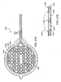
- the planar surface electrode includes an outer rim extending at least partially around an outer circumference of the electrode and a plurality of metallic struts formed in a pattern within the outer rim.
- the rim is discontinuous, thus enhancing collapsibility of the electrode.
- the rim includes one or more inward bends directed toward the struts, the inward bends adapted to promote collapsibility of the electrode.
- some of the struts are attached to other struts as well as to the outer rim. In other embodiments, the struts are attached only to the outer rim and not to one another.
- the struts are not attached at all to the outer rim, and may be attached to the housing through the material of the housing or other structure.
- the pattern of struts may include at least one area of more closely positioned struts relative to another area of less closely positioned struts, such that different areas of the electrode provide different amounts of energy transmission to the tissues.
- the pattern of struts may include at least one area of thicker struts relative to another area of thinner struts, such that different areas of the electrode provide different amounts of energy transmission to the tissues.
- the pattern of struts includes at least one fold line along which the electrode folds to allow the electrode to collapse.
- the struts are attached asymmetrically to the outer rim such that a first half of the housing and electrode folds into a second half of the housing and electrode when the housing and electrode assume their collapsed configurations.
- the struts are attached to the outer rim at between 8 and 16 attachment points to enhance collapsibility of the electrode.
- the device further includes a plurality of metallic attachment members extending from the outer rim for attaching the electrode to the housing.
- the plurality of attachment members may include an inferior attachment member for attaching proximally to an inferior portion of the housing and multiple superior attachment members for attaching proximally to a superior portion of the housing.
- the inferior attachment member extends onto an inferior portion of the catheter body, and the superior attachment members extend onto a superior portion of the catheter body.
- the inferior attachment member divides before attaching to the outer rim at two attachment points.
- the inferior attachment member curves asymmetrically before attaching to the outer rim.
- the struts are attached to the outer rim at locations apart from attachment points of the attachment members to the outer rim. Alternatively, the struts may be attached to the outer rim at attachment points of the attachment members to the outer rim.
- an electrode may include any of a number of additional features.
- the electrode further comprises at least one guidewire aperture to allow passage of a guidewire through the electrode.
- the guidewire aperture may be disposed along the electrode in an offset position to facilitate positioning of the electrode over the anatomic defect.
- Some embodiments include two offset guidewire apertures for facilitating positioning of the electrode over the anatomic defect.
- Some embodiments further include a thermocouple attached to the electrode.
- the energy transmission member comprises a radiofrequency electrode having multiple planar surfaces connected by one or more bends, such as a "stepped" electrode.
- a radiofrequency electrode having multiple planar surfaces connected by one or more bends, such as a "stepped" electrode.
- such an electrode may have a first planar surface, a bend, and a second planar surface.
- the housing may also have such a stepped, or "multiplanar,” configuration that matches that of the electrode.
- the energy transmission member may comprise a planar, expandable, braided wire electrode.
- a method of treating an anatomic defect in human tissue involves: positioning a distal end of an elongate catheter device at the site of the anatomic defect; exposing an expandable housing and energy transmission member out of the distal end of the catheter device; engaging the housing with tissues at the site of the anatomic defect; applying suction to the tissues via the housing to bring the tissues together; and applying energy to the tissues with the energy transmission member to substantially close the anatomic defect acutely.
- the method further involves repositioning the housing and the energy transmission member within the catheter device and removing the catheter device from the site of the anatomic defect.
- substantially it is meant that a stable tissue bridge will be formed across the anatomic defect, which will withstand physiologic pressures.
- a substantially closed anatomic defect may still have one or more small gaps or openings, which will in at least some cases close over time via the healing process.
- acute closure it is meant that the anatomic defect is substantially closed when the closure procedure is completed.
- acute closure distinguishes devices and methods of the present invention from prior protocols, which rely on delayed anatomic defect closure via tissue healing and scarring.
- acutely does not mean temporarily, apparatus embodying of the present invention and the described methods will typically provide for permanent (or at least long-term) anatomic defect closure.
- exposing and repositioning the housing and the energy transmission member involve moving a sheath of the catheter device relative to a catheter body of the catheter device.
- repositioning the housing and the energy transmission member may involve advancing the sheath and/or retracting the catheter body to cause the housing and the energy transmission member to collapse as they enter the sheath.
- the housing and energy transmission member collapse along one or more lines of structural weakness adapted to promote collapsibility.
- collapsing of the housing and energy transmission member comprises one lateral side of the housing and energy transmission member folding over an opposite lateral side.
- the method may further involve passing fluid out of an irrigation fluid aperture in the housing and suctioning the fluid back into a suction aperture in the housing.
- the method may further comprise directing the fluid, via multiple channels on an inner surface of the housing, away from the irrigation fluid aperture and toward the suction aperture.
- the multiple channels could be used to direct the irrigation fluid away from the fluid aperture and over targeted areas of the electrode to cool the electrode, wholly or in selected regions, to prevent the electrode from adhering to the tissue.
- Some examples also include monitoring the suctioned fluid to determine the blood content of the fluid. Alternatively or additionally, a flow rate of fluid from a fluid supply reservoir into the catheter may be monitored to determine whether a seal has been formed.
- engaging the housing with the tissues automatically engages the energy transmission member with the tissues.
- applying suction to the tissues automatically engages the energy transmission member with the tissues.
- Still other examples further involve moving the energy transmission member relative to the housing to engage the energy transmission member with the tissues. These latter examples may optionally also involve repositioning the energy transmission member relative to the housing to engage the tissues at a different location.
- the energy applied to the tissues may include, but is not limited to, radiofrequency, microwave, ultrasound, laser, heat and/or cryogenic energy.
- the energy is applied at different levels to different areas of tissue via the energy transmission member.
- the different levels of energy may be applied via different densities of material comprising the energy transmission member.
- the different levels of energy are applied via multiple energy delivery devices coupled with the energy transmission member at different regions of the ETM.
- FIG. 1 is a diagram of the fetal circulation
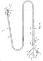
- FIG. 1A is a perspective view of a catheter device for treating an anatomic tissue defect according to one embodiment of the present invention
- FIG. 2 is a diagram of a catheter device for treating an anatomic tissue defect (exemplified as a PFO), the catheter passing through the inferior vena cava and into the right atrium, with a guidewire extending through the defect;
- an anatomic tissue defect illustrated as a PFO
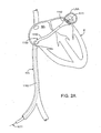
- FIG 2A is a diagram of a catheter device for treating an anatomic tissue defect (exemplified as a left atrial appendage (LAA)), the catheter passing through the inferior vena cava, across the interatrial septum, and into the left atrium to the mouth of the LAA;
- LAA left atrial appendage
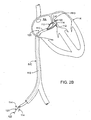
- FIG. 2B is a diagram of a catheter device for treating an anatomic tissue defect (exemplified as a PFO), the catheter passing through the inferior vena cava and into the right atrium, with a guidewire extending through the defect;
- an anatomic tissue defect illustrated as a PFO
- FIG. 2C is a perspective view of a distal end of a catheter device for treating an anatomic tissue defect
- FIG. 2D is a perspective view of a distal end of a catheter device for treating an anatomic tissue defect according to another embodiment of the present invention.
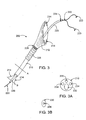
- FIG. 2E is a side view of a distal end of a catheter device for treating an anatomic tissue defect, including a curved reinforced catheter shaft according to one embodiment of the present invention
- FIG. 2F is a side view of a distal end of a catheter device for treating an anatomic tissue defect according to an embodiment of the present invention, including an electrode and an electrode housing with struts according to one embodiment of the present invention;
- FIG 2G ', 2G" and 2G"A are inferior, superior and end-on views, respectively, of an electrode housing of a catheter device according to one embodiment of the present invention
- FIG. 3 is a perspective view of a distal end of a catheter device for treating an anatomic tissue defect
- FIG. 3A and 3B are cross-sectional views of the catheter device in FIG. 3 ;
- FIG. 4 is a perspective view of a distal end of a catheter device for treating an anatomic tissue defect
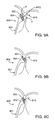
- FIGS. 5A and 5B are perspective views of a distal end of a catheter device for treating an anatomic tissue defect
- FIG. 6 is a perspective view of a distal end of a catheter device for treating an anatomic tissue defect
- FIG. 7 is a perspective view of a distal end of a catheter device for treating an anatomic tissue defect
- FIGS. 8A-8C demonstrate a method for treating an anatomic tissue defect (exemplified by a PFO) using a catheter apparatus;
- FIGS. 9A-9E demonstrate another method for treating a PFO using a catheter apparatus
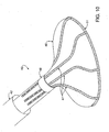
- FIG. 10 is a perspective view of the distal-most end of a catheter device for treating an anatomic tissue defect
- FIG. 11 is an inferior view of the distal-most end of the catheter device in FIG. 10 ;
- FIG. 12 is a cross-sectional side view of the distal-most end of a catheter device for treating an anatomic tissue defect according to one embodiment of the present invention.
- FIG. 12A is a cross-sectional side view of the distal-most end of a catheter device for treating an anatomic tissue defect, including a stepped housing and electrode, according to another embodiment of the present invention.
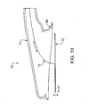
- FIG. 13 is a cross-sectional side view of the distal-most end a catheter device for treating an anatomic tissue defect, including a movable electrode according to another embodiment of the present invention
- FIG. 14 is an inferior view of a distal housing of a catheter device for treating an anatomic tissue defect, showing irrigation fluid circulation through the housing according to one embodiment of the present invention
- FIG. 15 is an inferior view of a distal housing of a catheter device for treating an anatomic tissue defect, showing an electrode with a discontinuous rim to enhance collapsibility;
- FIG. 15A is an inferior view of a distal end of a catheter device for treating an anatomic tissue defect, having a fan-shaped, laterally collapsible electrode with a discontinuous rim and fan-shaped housing to enhance collapsibility;
- FIG. 15B is an inferior view of a distal end of a catheter device for treating an anatomic tissue defect, having a fan-shaped, laterally collapsible electrode with no outer rim and a fan-shaped housing to enhance collapsibility;
- FIG. 15C is an inferior view of a distal end of a catheter device for treating an anatomic tissue defect, having a fan-shaped, laterally collapsible electrode with no outer rim and a circular housing to enhance collapsibility;
- FIGS. 15D and 15E are bottom and side views, respectively, of a distal portion of a catheter device for treating an anatomic tissue defect, including a fan-shaped housing to enhance collapsibility according to one embodiment of the present invention
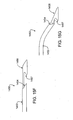
- FIGS. 15F and 15G are side views of a distal portion of a catheter device for treating an anatomic tissue defect, having a sheath with a slanted distal end;
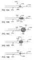
- FIGS. 16A-16E are diagrammatic illustrations of a distal end of a catheter device, demonstrating a method for exposing and retracting a distal housing and electrode of the device;
- FIG. 17 is a top view of an electrode with attachment members for use in a catheter device for treating an anatomic tissue defect
- FIG. 18 is a top view of an electrode with attachment members for use in a catheter device for treating an anatomic tissue defect; ;
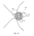
- FIG. 19 is a top view of an electrode with attachment members for use in a catheter device for treating an anatomic tissue defect
- FIG. 20 is an electrode pattern for use in a catheter device for treating an anatomic tissue defect
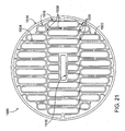
- FIG. 21 is an electrode pattern for use in a catheter device for treating an anatomic tissue defect
- FIG. 21A is a layered PCB electrode with encapsulated, disconnected electrode surfaces
- FIG. 21B is a cross-section of a layered PCB electrode with encapsulated, disconnected electrode surfaces
- FIG. 22 is an electrode pattern for use in a catheter device for treating an anatomic tissue defect.
- FIG. 23 is an electrode pattern for use in a catheter device for treating an anatomic tissue defect.
- FIGS. 24A-24C are electrode patterns according to various alternative examples. .
- the present invention provides apparatus as set out in claim 1.
- Devices and methods are described that generally provide for treatment of anatomic defects in human tissue, such as patent foramen ovale (PFO), atrial septal defect, ventricular septal defect, left atrial appendage (LAA), patent ductus arteriosis, vessel wall defects and/or the like through application of energy.
- electrophysiological defects such as atrial fibrillation, supraventricular tachacardia (SVT), atrial flutter, A-V node re-entry, and Wolf Parkinson White syndrome, may be treated using various embodiments of the present invention. Therefore, although the following descriptions and the referenced drawing figures focus primarily on treatment of PFO, any other suitable tissue defects, such as but not limited to those just listed, may be treated in various embodiments.
- Figure 1 is a diagram of the fetal circulation.
- the foramen ovale is shown, with an arrow demonstrating that blood passes from the right atrium to the left atrium in the fetus.
- the foramen ovale fails to close (thus becoming a PFO)
- blood may travel from the right atrium to the left atrium or vice versa, causing increased risk of stroke, migraine and possibly other adverse health conditions, as discussed above.
- a catheter device 10 for treating an anatomic tissue defect includes an elongate catheter shaft 12 having a proximal end 12b and a distal end 12a, a sheath 14 (or “sleeve") disposed over at least part of shaft 12, a handle 24 coupled with a proximal end of sheath 14, and a collapsible housing 16 coupled with catheter shaft distal end 12a.
- Coupled with housing 16 are a distal flexible foot 20 for contacting tissue, an electrode 19 (or other suitable energy transmission member in alternative embodiments) for transmitting radiofrequency (RF) energy to tissues, attachment members 17 (or “struts”) for coupling electrode 19 with housing 16 and for providing support to housing 16, and a radiopaque marker 18 for coupling attachment members 17 with housing 16 and/or catheter body distal end 12a and for facilitating visualization of device 10.
- a guidewire 22 is passed through catheter 10 from the proximal end through the distal end.
- catheter body proximal end 12b includes an electrical coupling arm 26, a guidewire port 32 in communication with a guidewire lumen (not shown), a fluid infusion arm 34 in fluid communication with the guidewire lumen, and a suction arm 29 including a suction port 27, a fluid drip port 28, a valve switch 30 for turning suction on and off.
- Fluid drip port 28 allows fluid to be passed into a suction lumen to clear the lumen, while the suction is turned off.
- a flush port 36 is coupled with sheath 14 and extends through an opening 37 in handle 24. Flush port 36 allows fluid to be introduced between sheath 14 and catheter body 12, to flush that area, and its connection to sheath 14 and passage through opening 37 prevents rotation of sheath 14 relative to catheter body 12.
- catheter device 10 Many of the above-mentioned features are described in further detail below. In alternative embodiments, additional features or fewer features may be included on catheter device 10. For example, a number of modifications may be made to catheter body proximal end 12b without departing from the scope of the invention. Therefore, the following description is intended to be primarily exemplary in nature and should not be interpreted to limit the scope of the invention as it is described in the claims.
- catheter device 1100 for treating an anatomic tissue defect is shown within a cross-section of a heart H, in position to treat a PFO.
- catheter device 1100 may be advanced through the inferior vena cava IVC into the right atrium RA of the heart H.
- Catheter device 1100 generally includes a sheath 1110, a collapsible housing 1112 extending from the distal end of sheath 1110, and an electrode 1113 (or one or more other energy transmission members, in alternative embodiments) coupled with housing 1112.
- catheter device 1100 may be advanced over a guidewire 1111 extending through a PFO or other tissue defect.
- Electrode 1113 comprises a planar, metallic electrode disposed within or near the distal end of housing 1112, as will be described in further detail below in reference to Figures 2C through 2G .
- Housing 1112 acts as a vacuum application member to contact and apply vacuum to tissues to bring them together. For example, vacuum may be applied via housing 1112 to septum primum and septum secundum tissues of the PFO to bring those tissues together. RF energy is then transmitted to the tissues via electrode 1113 to close the PFO, as will be described further below.
- FIG. 2A shows catheter device 1100 from Figure 2 , advanced over a guidewire 1111 and to the mouth of a left atrial appendage (LAA) defect.
- Vacuum is applied via housing 1112 to approximate the tissue at the mouth of the LAA, seal or flatten the defect (shown in dotted lines), and trap any clot residing in the defect, to prevent it from embolizing.
- the vacuum may cause the mouth of the LAA to close, or it may cause the LAA to empty and lay flat, approximating one edge of the mouth to the tissue on the opposite inner wall of the LAA (also shown in dotted lines), or it may approximate tissue in some other geometry.
- FIG. 2B depicts a catheter device 100 for treating an anatomical tissue defect.
- This catheter device 100 includes an elongate sheath 110, one or more tissue apposition members 112 extendable out of the distal end of sheath 110, and one or more energy transmission members 114 coupled with tissue apposition members 112.
- Catheter device 110 may be slidably disposed over a guide member 120, such as a guide catheter, a guidewire, or the like.
- Guide member 120 may include, for example, an inner guidewire 122 with an expanding or split distal end or other similar features for deploying within the PFO to help appose the adjacent tissues.
- the split and/or expandable distal end of guidewire 122 may comprise (or be coupled with) one or more energy transmission members 114.
- catheter device 100 is generally used to bring together tissues surrounding and/or adjacent the PFO or other anatomical tissue defect and transmit energy to the tissues to close or treat the defect.
- treatment device 1200 includes a catheter body, having a flexible neck 1228 to allow for deflection and/or active steering, and a radiopaque marker 1226.
- Figure 2D depicts a neck 1328 that has a preformed bend.
- a planar electrode 1213 for transmitting RF energy is disposed.
- the embodiment shown in Figure 2D demonstrates several additional optional features of a tissue treatment device 1300, and in particular a tissue apposition member.
- a tissue apposition member may include a vacuum application housing 1312, for example, may include multiple ribs 1322 or ridges, grooves or the like, to provide support to vacuum housing, thus preventing its collapse when vacuum is applied.
- Vacuum housing 1312 itself may be made of any suitable material or combination of materials, such as but not limited to any suitable polymers.
- Ribs 1322 may be made of the same or different material as the rest of housing 1312, and are generally thickened or heightened portions of material.
- multiple struts 1317 ( Figure 2F ) may be embedded within or attached to the wall of housing 1312 for providing similar support. Struts 1317 may also be separate from the housing and attached to the catheter shaft and electrode to allow for torque of the electrode itself.
- guidewire lumen 1315 as detailed below may serve a similar function, eliminating the need for strut elements.
- Grooves or valleys on the inner surface of housing 1312 between ribs 1322 may also enhance flow of substances, such as blood or infused fluid.
- tissue apposition member of tissue treatment device 1300 includes a flexible foot 1316 at the distal end of vacuum housing 1312.
- flexible foot 1316 may comprise simply an extension of the material of housing 1312, or in other embodiments it may comprise a different material.
- foot 1316 is formed by recessing electrode 1313 within vacuum housing 1312.
- foot 1316 comprises an asymmetric cylinder including a taller side 1316a and a sorter side 1316b. Such an asymmetric foot 1316 may facilitate creation of a seal between foot 1316 and tissues that are being brought together.
- foot 1316 is made of a flexible polymer such as those set forth above in this specification, or other material so as to promote engagement of foot 1316 with tissues while preventing unwanted tissue damage. Foot 1316 is also adapted to not roll in on itself when engaged with tissue, but to be conformable to the tissue to accommodate and seal over the geometry of the tissue defect which may include varying tissue depth or elevations, oddly shaped or sized perimeter, or multiple defects (such as in multiple flaps found in PFOs, or inhomogeneous tissue (e.g. thin and thicker). Foot 1316 may be formed of a material such as silicone that can be molded such that the periphery of the foot cylinder may be thinner than the main body. Given the variability of certain defects and the desirability of having a catheter design that accommodates varying tissue geometry, it may be desirable to design the foot 1316 to expand or contract distance D as shown in Figure 2F .
- Figure 2E further depicts the catheter 1300 and housing 1312.
- Catheter shaft 1310 may be formed of a braided construction to allow for kink resistance, pushability and torqueability of catheter shaft 1310 to the desired placement. To further facilitate placement and positioning of catheter shaft 1310, it may sometimes be desirable to torque the catheter from side to side and/or to advance the device over more than one guidewire.
- Figure 2G ' shows such an embodiment of a housing 1312 having multiple, asymmetric guidewire apertures 1314.
- neck portion 1328 ( Figure 2E ) may be preformed to have a radius of curvature ( ⁇ between a range of 0 to 90 degrees) to facilitate positioning of catheter 1300 over a tissue defect.
- One or more structural elements such as a struts 1317, a resilient mesh embedded in the housing and/or a torque cable or rod attached to the electrode may be incorporated to allow the electrode and housing 1312 to be torqued and maneuvered.
- One such housing 1312 is further detailed in Figures 2F-2G ", showing struts 1317 optionally embedded into housing material to provide control and rigidity to housing 1312 when shaft 1310 is torqued.
- Struts may extend the length of the catheter, or be terminated at the point of the radiopaque marker (RO) on the catheter shaft.
- struts may be truncated to only run a partial length of the housing as shown in Figure 2G " 1350.
- strut may be a single element that is rigidly coupled to the electrode to assist in lowering the profile of the housing while still allowing torque of the electrode.
- Struts may further incorporate radiopaque markings 1340 to assist in visual orientation of the catheter under fluoroscopy, ultrasound, or other imaging modalities.
- markings 1340 as shown in Figure 2G " may include an asymmetric component 1341 on the housing to assist the user in differentiating the right side from the left side of the catheter housing.
- Markings may be formed from techniques known in the art such as plating, use of metal markers such as tantalum, platinum, stainless steel, or imbuing contrast agents into the catheter material such as barium sulfate and the like.
- the electrode and housing 1312 may be retracted into catheter sheath 1351 for introduction and removal of the device in a percutaneous manner.
- a housing measuring about 0.50 inch in diameter may be retracted into or deployed from a shaft opening having a diameter of about 0.10 inch.
- the housing may measure about 1.0 inch and be capable of collapsing into a catheter shaft with a diameter of about 0.18 inch.
- Apparatus 200 includes a catheter device 210 coupled with a tissue apposition member 212 at its distal end.
- One or more energy transmission members 214 may be disposed through or within catheter device 210 and/or coupled with tissue apposition member 212.
- Catheter device 210 may be slidably disposed over a guide catheter 220.
- Guide catheter 220 may contain one or more expandable elements 222, such as a guide wire or the like.
- One or more radiopaque markers 224, 226 may be included on catheter device 210, guide catheter 220 or both.
- Catheter device 210 may also include an isolation portion 228 for helping to stabilize tissue apposition member 212 during use, so that it is not caused to move due to the flexibility of catheter device 210.
- FIG. 3A show cross-sectional views of apparatus 200 from the perspective of lines A and B in Figure 3 , respectively.
- catheter device 210 is shown, having a guide catheter lumen 232, two energy transmission member lumens 234 and a vacuum lumen 236.
- guide catheter 220 includes an expandable element lumen 238.
- Guide catheter lumen 232 may sometimes be configured with an inner diameter (or "profile") that is shaped (or "keyed”) to allow.guide catheter 220 to pass easily through lumen 232. This feature is demonstrated in Figures 3A and 3B , where guide catheter 220 and guide catheter lumen 232 each have an ovoid shape.
- catheter device 210 comprises an elongate, flexible catheter which may be advanced through the vasculature of a patient to a position in the heart for treating a defect.
- catheter device 210 may have any suitable length, diameter, cross-sectional profile and the like, and may be constructed of any suitable material.
- Tissue apposition member 212 (or multiple tissue apposition members in some embodiments) is disposed at or near the distal end of catheter device 210. Although many different types of devices may beused to bring tissues of the defect together, in one embodiment (shown in Figure 2 ) tissue apposition member 212 comprises a defect covering member.
- tissue apposition member 212 may be positioned to contact adjacent PFO tissues to fully cover, or block, the opening of the defect. In the case of treating a PFO, this blocking of the PFO may prevent right-to-left shunting of blood and may allow blood pressure in the left atrium to bring the septum primum and septum secundum at least partially together to close the PFO. Therefore, simply by forming a seal or blockage over the PFO, tissue apposition member 212 may help bring the PFO tissues together to assist in PFO closure.
- tissue apposition member 212 especially when configured as a PFO-covering member, may be collapsible/expandable to facilitate advancement and delivery of catheter device 210.
- tissue apposition member 212 may comprise a collapsible polymeric cover disposed over an expandable/collapsible frame.
- tissue apposition member 212 may be constructed of a shape memory material, such as nitinol or another shape memory metal, spring stainless steel or the like, to allow catheter device 210 to be delivered through vasculature and then allow tissue apposition member 212 to expand to contact and appose the PFO tissues.
- catheter device 210 and tissue apposition member 212 may be delivered to a location for PFO treatment through an introducer sheath.
- an angle between catheter device 210 and tissue apposition member 212 may be selected to approximate a convenient angle for delivery and/or deployment.
- the angle between catheter device 210 and tissue apposition member 212 may approximate the angle between the inferior vena cava and the interatrial septum. Any other configuration, combination of angles and the like is contemplated, however.
- direct steering of the angle of tissue apposition member 212 relative to catheter device 210 may be employed to enhance delivery of catheter device 210 to a treatment site.
- tissue apposition member 212 may also include one or more vacuum members for applying vacuum to the defect tissues or those surrounding the defect.
- suction lumen 236 ( Figure 3A ) may extend from the proximal end to the distal end of catheter device 210, opening into one or more vacuum-application apertures at the distal end of tissue apposition member 212.
- the vacuum-application aperture(s) may have any suitable configuration, such as a continuous aperture encircling tissue apposition member 212, multiple apertures encircling tissue apposition member 212 or in any other suitable configuration at or near its distal end, or the like.
- vacuum may be applied via a large, central lumen in tissue apposition member 212. In any case, vacuum force may be used to bring tissues together and/or to secure tissue apposition member 212 and thus catheter device 210 to the tissues.
- catheter device 210 may include one or more radiopaque markers 226 for facilitating visualization of the device 210.
- Catheter device 210 may also include a "flexible isolation portion" 228, which may comprise a rigid but shapeable portion disposed toward the distal end of catheter device 210, between tissue apposition member 212 and the generally flexible proximal portion of catheter device 210.
- Flexible isolation portion 228 may help to isolate tissue apposition member 212 from some or all movement experienced by the more flexible, proximal portion of catheter device 210, thus allowing a PFO treatment procedure to be performed without significant movement of tissue apposition member 212.
- flexible isolation portion 228 may be more flexible than the more proximal portion of catheter device 210, thus enhancing maneuverability, shapability or the like of the position of tissue apposition member 212 relative to the more proximal portion.
- Guide catheter 220 is generally a flexible catheter along which catheter device 210 may be slidably advanced to a position for defect treatment.
- Guide catheter 210 is configured to fit at least partially within or against the defect, and optionally through the defect such as into the left atrium of the heart when treating a PFO.
- one or more radiopaque markers 224 may be included on guide catheter.
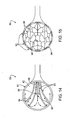
- Guide catheter 220 may contain one or more expandable members 222 or other similar devices for expanding within the defect to help bring the defect tissues together, anchor catheter device to the defect tissues, or both. As shown in Figure 3 , for example, a "fish mouth" or two-prong expandable member 222 may be deployed within a PFO.
- expandable members 222 may assist in PFO tissue apposition either while extending into the left atrium, while in other examples expandable members 22 do not extend into the left atrium.
- Expandable member 222 may have any suitable configuration and may be constructed from any suitable materials.
- expandable member 222 may be spring loaded, made of shape memory material, such as nitinol or spring stainless steel or the like.
- expandable member 222 may be expanded mechanically by one or more expansion members coupled with expandable member 222 and controlled via an actuator at the proximal end of guide catheter 220.
- expandable member 222 reside within guide catheter 220.
- Guide catheter 220 may then be withdrawn to deploy expandable member 222 either within the defect or in the case of a PFO treatment, within the left atrium to be drawn back into the PFO.
- expandable member 222 has one or more pre-shaped or shapeable distal tips 223.
- Tips 223 may be used, for example, to help locate and cross the defect. In the case of treating a PFO for example, tips 223 may also be used to contact a left atrial surface of the septum primum or other PFO tissue, so that when the expandable member 222 is pulled proximally tips 223 help bring the PFO tissues together and/or anchor apparatus 200.
- one or more expandable members 222 may include or be coupled with one or more energy transmission members.
- expandable member 222 may include one or more radiofrequency transmission members for monopolar or bipolar RF transmission.
- a fish mouth expandable member 222 may include a bipolar RF transmission member on each prong of the fish mouth.
- energy transmission members may be included in or coupled with both expandable member 222 and tissue apposition member 212.
- some portions of the energy transmission member(s) may be insulated, to prevent unwanted energy transmission to tissues.
- a distal tip extending to contact a left atrial surface of PFO tissues may be insulated to prevent energy transmission from the tip.
- an alternative example of a PFO-treatment apparatus 300 suitably includes a catheter device 310 having a tissue apposition member 312, radiopaque marker 326 and flexible isolation portion 328.
- a catheter device 310 having a tissue apposition member 312, radiopaque marker 326 and flexible isolation portion 328.
- apparatus 300 may also include a guidewire 320, over which catheter device 310 may be advanced.
- Guidewire 320 includes a split, expandable portion 322, which may be released from catheter device 310 to expand within a PFO to bring PFO tissues together.
- Guidewire 320 also suitably includes a distal tip 323 for locating and crossing a PFO and/or for contacting a left atrial surface of the septum primum or other PFO tissue.
- Apparatus 300 may include any of the features described above in relation to Figure 3 .
- apparatus 300 does not include a guide catheter, but instead includes guidewire 320.
- Guidewire 320 may serve many or all of the functions of the guide catheter and expanding member described above in reference to Figure 3 .
- Split portion 322 of guidewire 320 may be constructed of shape memory material or other suitable materials to allow it to expand when released from catheter device 310. Additionally, split portion 322 may include or be coupled with one or more energy transmission members instead of or in addition for energy transmission member(s) 314 coupled with tissue apposition member 312.
- Guidewire 320 may also include one or more distal tips 323, which again may be used to locate and cross a defect and/or to help appose defect tissues. Tip 323 may also include or be coupled with one or more energy transmission members.
- a defect-treatment apparatus 400 suitably includes a catheter device 410 having a tissue apposition member 412, radiopaque markers 426 and flexible isolation portion 428.
- apparatus 400 may also include a guidewire 420, over which catheter device 410 may be advanced.
- Guidewire 420 includes a split, expandable portion 422, which may be released from catheter device 410 to expand within a defect to bring defect tissues together.
- Guidewire 420 also suitably includes a distal tip 423 for helping locate and cross the defect and/or for contacting a left atrial surface of the septum primum or other defect tissue to help bring the defect tissues together.
- catheter device 410 also includes a braided portion 430 which includes the proximally-disposed tissue apposition member 412 and a more distal energy transmission portion 432, the latter of which is coupled with energy transmission members 414.
- Tissue apposition member 412 and energy transmission portion 432 may be a unitary braided member, with tissue apposition member 412 configured to cover energy transmission portion 432 in a retracted position and to provide vacuum force application.
- catheter device 410 is typically advanced over guidewire 420 to a treatment location.
- Split portion 422 and optionally distal tip 423 are then used to help appose the tissues adjacent the defect.
- energy transmission portion 432 is retracted into tissue apposition member 412. Defect tissue is then brought together using tissue apposition member 412, and energy is transmitted to the tissues using energy transmission portion 432.
- tissue apposition member 412 provides for application of vacuum energy to the tissues to suction the tissues at least partially into tissue apposition member 412, thus enhancing contact of the tissues with energy transmission portion 432.
- Energy transmission portion 432 may comprise, for example an electrode mesh material, while tissue apposition member 412 may comprise an elastic coated mesh or other material. Again, any features described above in reference to other embodiments may be applied to the examples shown in Figures 5A and 5B .
- tissue apposition member 512 includes ribs or "bellows" 540 to facilitate placement and/or alignment of tissue apposition member 512 relative to the septal wall tissues to be treated and/or to enhance adherence of apparatus 500 to the septal wall.
- ribs 540 may allow catheter device 510 to move relatively freely relative to tissue apposition member 512, without displacing tissue apposition member 512 from the defect tissues.
- tissue apposition member 612 includes multiple struts 650 covered by a covering 652, which may comprise a polymeric covering or any other suitable material.
- Struts 650 may be self-expanding or may open via a mechanical opening actuator coupled with struts 650, such as opening apparatus used to open an umbrella.
- Energy transmission members 614 are coupled with self-expanding struts 650 on the internal surface of tissue apposition member 612, so as to contact defect tissue that is pulled within tissue apposition member 612, such as by applied vacuum force and/or by blood pressure from the left atrium.
- devices of the invention apply energy tissues using one or more energy transmission members (ETM).
- ETMs are typically described as electrodes, such as RF electrodes, for example as electrodes 214, 313, 314, 1213, 1313.
- an ETM may comprise any of a number of devices and may transmit any suitable type of energy for closing a n anatomic defect.
- Some types of energy which may be used include radiofrequency, cryogenic, resistive heat, ultrasound, microwave and laser energy.
- Radiofrequency ETMs may be either monopolar or bipolar, with monopolar catheter devices also including a grounding member.
- Energy transmission members may have any suitable configuration.
- ETM may have a curved shape to approximate a radius of curvature of the defect, as shown in Figure 3 , or they may be configured as points for spot-welding the defect tissues, as a circular member for welding around the circumference of defect tissues, as one or more mesh or braided members disposed within the orifice of tissue apposition member 212 or the like.
- ETM may take the form of a planar electrode such as those shown in Figures 2D-2G ".
- ETMs are fixedly coupled with tissue apposition member 212, while in other examples ETMs are movable within tissue apposition member, for example to move about the circumference of the defect to weld defect tissues at multiple locations.
- ETM comprises a planar electrode 1313, which may have any suitable configuration and be made of any suitable material(s) in various examples and embodiments. Electrode 1313 may also be attached to vacuum housing 1312 by any suitable means, such as adhesives, welding or the like. In one example, electrode 1313 may include one or more attachment members, such as prongs or the like, which extend from the planar surface of electrode 1313 and are embedded in or attached to a surface of housing 1312.
- Planar electrode 1213 may comprise any suitable metallic material such as Nitinol, Elgiloy®, titanium, platinum, cobalt chromium, stainless steel or spring steel or other resilient material and be a wire mesh, a flexible circuit, a patterned metallic surface, or the like. Planar electrode 1213 may be formed from a single sheet, by being laser cut, photochemically etched, electron-discharge machined (EDM) or other useful processes known in the art. Furthermore, planar electrode 1213 may be plated or surface treated to be radiopaque and/or echogenic. Such plating may also allow for improved current conduction, and may be useful to create variable thickness electrodes that provide different current conductivity along the surface of one electrode. Platings or coatings may also serve as a "non-stick" surface to minimize tissue or blood debris from accumulating on the electrode.
- EDM electron-discharge machined
- Electrode 1213 also includes a guidewire port or ports 1214 for passage of a guidewire 1211.
- Guidewire port 1214 may be centrally located on the electrode face, or offset depending on the desired approach to the defect.
- the outlet of guidewire port 1214 may have a counter-bored, chamfered or rounded leading edge to provide for smooth guidewire passage.
- electrode 1313 may have one or more than one guidewire port 1314. Is some cases, guidewire port 1314 is centered on electrode 1313, while in other embodiments, one or more guidewire ports 1314 may be located off-center on electrode 1313 as in Figure 2C .
- Off-center or eccentric guide ports 1314 may facilitate localization and/or positioning of housing 1312 relative to a tissue defect such as a PFO, and may assist in the collapsibility of the housing 1312 for deployment purposes.
- Guidewire port 1314 may be an aperture in the electrode face, and may be further formed of a lumen or hypotube 1315 that extends into the catheter body to allow the operator to easily exchange guidewires, or insert guidewires at separate points during the procedure as desired. It may be desirable to form the guidewire port 1314 to include a ramp 1314a to predetermine the angle of outlet of the guidewire so that it exits at the desired trajectory.
- a guidewire 1311 with an expandable balloon may be used to inflated within a tissue defect or beyond in the heart chamber (e.g. right atrium) to bias vacuum housing 1312 in a desired direction.
- a balloon may be incorporated on the catheter shaft or guide to achieve a similar purpose.
- FIG. 2G further depicts a thermocouple (TC) and the electrical connection wire (EC) that can be fixed to the face of electrode 1313.
- TC thermocouple
- EC electrical connection wire
- catheter shaft 1310 includes one or more guidewire lumens 1342, an electrode lumen 1343, a thermocouple lumen, and an infusion port 1344. Vacuum may be applied through a separate lumen (not shown) or the annular space 1345 within the catheter body.
- tissue welding herein is used to mean application of energy to (or removal of energy from) defect tissues to substantially and acutely close the defect.
- Energy transmission members generally provide for transfer of energy to or from PFO tissues to denature collagen in the tissues, and when the collagen is allowed to renature, with the tissues apposed, the once separated tissues bind together to form a stable tissue bridge. This stable tissue bridge substantially and acutely closes the PFO, preferably permanently.
- PFO tissues may be brought and held together by one or more tissue apposition members 212.
- Energy transmission members provide sufficient energy transfer, for a sufficient time, to weld the tissues.
- the time span of energy transmission may be, for example, from about 0.5 seconds to about 15 minutes, and more preferably from about 30 seconds to about 5 minutes.
- Energy transmission may be from about 0.5 Watts to about 100 Watts, and more preferably from about 2 Watts to about 40 Watts. Any other suitable energy and timing combination may also be used.
- a PFO in a section of pig heart tissue used ex-vivo in a flowing saline test fixture was closed by applying suction to appose the PFO tissues and applying RF energy at approximately 25 watts for 7minutes. RF energy application was then discontinued, but suction was continued for an additional 1 minute to keep tissues in apposition while the tissue cooled, to allow collagen in the tissues to reorganize and bind together to form a stable tissue bridge.
- Many other energy amounts, energy application times, tissue apposition times and the like are contemplated, however.
- a variety of temperature, power and time combinations may be used.
- ETMs Although any type of energy may be transmitted by ETMs, some will make use of monopolar or bipolar RF energy.
- Devices may use monopolar radiofrequency energy, for example, wherein energy is applied simultaneously to all conductive elements, completing the circuit through an external ground pad affixed to the skin of the patient.
- bipolar energy may be applied to all conductive elements simultaneously, and the circuit completed through a ground element incorporated elsewhere on apparatus 200. Further examples and embodiments may include applying bipolar energy between two or more ETMs, which are electrically isolated from one another within catheter device 210.
- Control systems coupled with ETM or tissue apposition member 212, or otherwise disposed within apparatus 200 may sense an amount of energy delivered to PFO tissues and, optionally, may automatically stop energy delivery upon detecting a change in condition of energy delivery, for instance an increase in electrical resistance or impedance or rate of change in impedence, in PFO tissues or in apparatus 200, an increased energy draw from the treatment apparatus, and/or the like.
- Energy delivery may be automatically stopped when an amount of delivered energy reaches a desired level, such as an amount of energy sufficient to substantially close the PFO.
- the amount of delivered energy may be monitored by any suitable method, such as monitoring temperature or impedance in PFO tissues or the like.
- One or more sensors coupled with tissue apposition member 212, ETMs, or any other part of apparatus 200 may be used for monitoring such indicia.
- sensor devices include but are not limited to infrared sensing devices, thermistors and thermocouples.
- a control system may also include a microprocessor coupled with the sensors to determine when a desired amount of energy has been delivered and/or to automatically stop energy transmission.
- a microprocessor may be included in apparatus 200 which can sense, monitor and control energy delivery, thus not requiring separate sensors.
- Figures 8A-8C demonstrate a method for treating a PFO. It should be emphasized that this is merely one possible exemplary method, and that many alternative methods are contemplated. For example, steps may be modified, repeated, added or deleted from the method, the order of steps may be changed, and/or the like. Therefore, the foregoing description should not be interpreted as in any way limiting the claimed invention.
- a PFO treatment method includes advancing a guide catheter 720 through the PFO, between tissues T adjacent the PFO, the guide catheter 720 containing an expandable member ( Figure 8A ).
- Guide catheter 720 is then retracted (proximally pointing arrow) to expose expanding member 722 ( Figure 8B ).
- Expanding member 722 may be exposed/expanded within the PFO, or may alternatively be exposed/expanded within the left atrium and pulled back into the tunnel of the PFO. Expanding member 722 may also include one or more distal tips 723, which may help to locate the PFO, cross the PFO, appose the tissues T and/or to anchor guide catheter 720 to the tissues T.
- catheter device 710 may be advanced over guide catheter 720 to a position for treatment of the PFO ( Figure 8C ).
- Catheter device 710 typically includes a tissue apposition member 712 (shown here in cross-section for clarity) and one or more energy transmission members 714. Suction may be applied using tissue apposition member 712, left atrial pressure may be used, or both, to bring tissues T adjacent the PFO together. Once tissue apposition member 712 is placed and/or activated, guide catheter 720 and expandable member 722 may be removed through catheter device 710, leaving the tissues T apposed and catheter device in place.
- guide catheter 720 and expandable member 722 may be left in place during a first welding to close the majority of the PFO and then removed.
- the small patent portions of the PFO remaining after the guide catheter 720 and expandable member 722 are removed may then be closed by a second weld or may be left open and allowed to close via healing or scarring.
- Tissue apposition member 712 may be used to hold tissues T together before, during and/or after energy transmission members 714 weld the tissues T together. Such holding of the tissues together and application of energy to weld the tissues may be performed for any suitable time, such as for less than one second to many minutes. Once a sufficient amount of energy has been applied to the tissues T to acutely close the PFO, catheter device 710 is removed, leaving a closed PFO.
- FIGS 9A-9E demonstrate another example of a method for treating a PFO. Such a method may also be used to treat other anatomic defects in human tissue, as discussed previously.
- a tissue treatment device 800 including a catheter body 801, a vacuum application member 804 and an electrode 802 is advanced along a guidewire 810 to a position near tissues T adjacent the PFO.
- a tissue treatment device 800 including a catheter body 801, a vacuum application member 804 and an electrode 802 is advanced along a guidewire 810 to a position near tissues T adjacent the PFO.
- advancing device 800 over an eccentrically positioned guidewire 810 actively steering a distal end of device 800, visualizing device 800 using radiopaque markers and flouroscopy or endoscopic devices such as flexible scopes, and/or the like, device 800 is generally positioned over the PFO.
- tissue T is held flat against the surface of the electrode. While such a presentation may not be exactly “flat” or “planar,” to account for various tissue imperfections or the fact that tissue may protrude into the interstices of the electrode face, the design of the electrode catheter facilitates an approach to the tissue T "en face,” or leading with the face of the electrode.
- an "en face” presentation may be advantageous not only because it presents the defect in a closed manner (e.g. in the case of a PFO the flap is flattened against the electrode surface), but also because it allows for efficient energy transmission to the tissue T (flat application surface can work to produce a more uniform surface thickness), thereby closing or treating the defect in a desirable treatment time.
- vacuum force may first be stored in a reservoir and may then be applied to the tissues T as an impulse of vacuum to quickly form a seal and thereby minimize loss of blood from the patient.
- the vacuum force applied ensures that the flap of the defect furthest from the vacuum application member is snugly apposed with the flap nearest thereto.
- applied vacuum force is typically sufficient to bring the tissues to be sealed in contact with each other.
- a number of PFO defects are accompanied by aneursysmal disease.
- a method may also tighten or reinforce the septum of the heart, thus also treating the aneurysmal disease.
- irrigation fluid may be circulated through device 800 to irrigate the area of energy application to the tissues T.
- Such irrigation fluid may be circulated within vacuum housing 804, for example, by introducing fluid through a lumen of device 800 and then using the vacuum force to bring the fluid back into the lumen.
- fluid flushing is used to prevent clotting and/or blood accumulation in housing 804.
- a nonconductive fluid such as heparinized D5W may be used.
- saline may be used to prevent clotting within the patient and/or device 800 (e.g., electrode housing, catheter lumen(s), or the like). Saline may also be employed to affect the heating characteristics of the desired treatment. Infusion may also act to cool the tissue interface, thereby preventing rapid tissue necrosis.
- the procedure may be monitored in several ways.
- the fluid brought back through device is monitored for color, to determine when there is little or no blood in the fluid, thus helping to determine when a seal has been acquired and/or the PFO is closed. It may also be desirable to measure the impedance of the treatment region to determine if a seal is being maintained (impedance of blood is lower than tissue, so a change may indicate the presence of blood (leak) or lack of seal).
- an optical detector may be employed to control vacuum and shut off the force if blood is detected in the evacuated fluid.
- the rate of extraction of fluid may be monitored and calculated to ensure that the rate of extraction equals that of infusion.
- infuse fluid "passively" from an IV fluid bag
- a suction lock apparatus as is known in the art, may be employed on the proximal end of the catheter to ensure that fluid is not inadvertently extracted from the patient.
- the rate of extraction of the fluid from the supply reservoir e.g. an IV bag
- the rate of extraction of the fluid from the supply reservoir may be monitored to detect whether or not a seal against the tissue has been achieved. If a seal is achieved, the flow rate from the reservoir will increase. If a seal has not been achieved, or has been lost, passage of blood into the housing will predominate, slowing the flow rate from the reservoir.
- the PFO has been closed and guidewire 810 has been withdrawn.
- guidewire 810 is withdrawn after energy is applied and the PFO is closed, thus leaving a small hole in the closed PFO where guidewire 810 used to reside. Nevertheless, the PFO is still substantially closed, and the small hole left by guidewire 810 will typically close naturally, due to scarring.
- device 800 is removed, leaving a substantially closed PFO. After the defect is closed, it may be desirable to maintain apposition of the defect tissue while tissue cools back down to body temperature, although this is not necessarily required for effective tissue bonding. In addition, it is within the scope of this disclosure to perform multiple applications of the energy device to treat the defect.
- the device multiple times, or re-treating a defect that may re-cannulate following the initial treatment at a time period separate from the initial treatment.
- the balloon could be positioned in the defect and inflated until the balloon diameter is as large as the defect, while the clip and tines are proximal to the defect.
- the balloon and clip could then be advanced through the defect until the tines of the clip pierce the tissue surrounding the defect.
- the balloon could then be deflated, causing the clip to also contract radially, gathering the tissues together.
- Energy would then be applied to the tissue, either using the clip itself as the electrode, or an electrode on the surface of the balloon, or an entirely separate electrode. This energy would serve to weld the tissues in their gathered state.
- the balloon and clip could be withdrawn from the tissue, leaving the welded defect with little or no residual opening.
- a PDA might also be closed using the balloon device described in the material incorporated immediately above, which would gather the tissue of the walls of the PDA together before applying energy.
- tissues adjacent the defect are brought at least partially together and energy is applied to the tissues to acutely close the defect with fewer steps and/or fewer device components than just described.
- energy is applied to the tissues to acutely close the defect with fewer steps and/or fewer device components than just described.
- suction to appose tissues is not required in all examples.
- a variety of different types of energy may be applied to the tissues from a variety of differently configured energy transmission devices.
- one or more of the steps described above may be repeated one or more times, such as by repeating a tissue welding step. The above description, therefore, is provided for exemplary purposes only.
- a distal end of a catheter device 40 for treating anatomical tissue defects includes a housing 46, an electrode 51 coupled with housing 46, multiple struts 47 (or “attachment members") for attaching electrode 51 to housing 46 and providing support, a radiopaque marker 48 for attaching struts 47 to housing 46 and promoting visualization, and a sheath 42 through which housing 46 and electrode 51 are delivered to a location for performing a procedure.
- housing 46 and electrode 51 are typically collapsible, so as to fit within and be passable through sheath 42. Both housing 46 and electrode 51 may be given any of a number of different features to provide for collapsibility. For example, resilient materials may be used, some portions of housing 46 and electrode 51 may be structurally weaker than other portions to promote folding or collapsing along the weaker portions, or the like.
- FIG 11 shows an inferior view of housing 46 and electrode 51.
- Housing 46 generally includes a proximal neck portion 55 and a distal collapsible portion S6.
- Collapsible portion 56 may have any of a number of shapes, such as circular (as shown), ellipsoid, ovoid, rectangular, square, triangular, hexagonal, octagonal or the like.
- Neck 55 typically attaches proximally to a catheter body (not shown). The catheter body may simply extend into housing 46, with the body and housing 46 being a single piece or extrusion.
- Electrode 51 generally includes an outer rim 53, multiple electrode struts 52 (or wires) extending from one side of rim 53 to the other, and a guidewire opening 54 within electrode struts 52 to allow for passage of a guidewire. Electrode 51 may have any of a number of configurations, and electrode struts 52 may be disposed in any suitable pattern, some of which are described in further detail below. Attachment member struts 47 are also shown. One example includes five struts 47, four of which extend over the top of housing 46, and one strut 47' extending proximally along the inferior surface of neck 55. Inferior surface strut 47' thus typically is shorter and may have a different shape than other struts. In alternative examples, any number, shape and size of attachment struts 47 may be used.
- a cross-sectional side view of a distal end of a catheter device 60 shows a housing 61, an electrode 62 housed within housing 61, and a flexible foot 58 extending from housing 61 and configured to contact tissues adjacent a tissue defect.
- Foot. 58 has a distal side 58a with shorter height than a proximal side 58b, this configuration facilitating tissue contact and formation of a vacuum seal on the tissue.
- a guidewire 64 may be passed through housing 61 and electrode 62 for guiding the catheter device to a location for performing a treatment procedure.
- a catheter device 70 includes a housing 71 with a flexible foot 68 and a movable electrode 72 coupled with a movable energy delivery device 73.
- Movable electrode 72 is a planar, collapsible electrode that is free to move relative to housing 71.
- electrode 72 may be moved proximally, distally, superiorly and inferiorly (solid and hollow doubled-tipped arrows).
- a movable electrode 72 a user may achieve a suction seal on tissue with housing 71, contact electrode 72 with tissue, apply energy to the tissue, and then move electrode 72 to another location within flexible foot 68 and apply more energy, without breaking the seal.
- foot 68 may be substantially wider than electrode 72, allowing energy to be applied to multiple different sites using the same seal.
- a catheter device 80 includes a distal housing 81 (shown here with electrode removed for clarity) and a fluid infusion tube 88 coupled with an inner surface 82 of housing 81.
- Inner surface 82 includes multiple surface features 83, 84, 86 for directing fluid around housing 81 during a procedure.
- surface features include multiple ridges 83, depressions 84 (or channels) between ridges 83, and one or more fluid backstops 86.
- Backstop 86 prevents fluid exiting infusion tube 88 from backing up into infusion tube 88, and ridges 83 and depressions 84 help guide fluid around the inner cavity of housing 81 (see solid-tipped arrows).
- infused fluid flows out of tube 88, around interior of housing 81, and back into a suction lumen 85 toward the proximal side of housing 81.
- ridges 83, channels 84 and backstop 86 may have any of a number of suitable shapes, sizes and numbers for directing fluid in a desired direction.
- FIG. 15 shows an alternative example of a catheter device 90 for treating anatomical tissue defects.
- catheter device 90 includes a housing 94 and an electrode having multiple, discontinuous rim segments 92 and electrode struts 96 coupled with segments 92 and forming a guidewire opening 98.
- rim segments 92 instead of a continuous rim promotes collapsibility of both housing 94 and the electrode.
- an electrode may generally have a fan shape and may be adapted to laterally collapse.
- laterally collapsible it is meant that the electrode is adapted to collapse by having two opposite side draw closer to one another, similar to a collapsible, hand-held fan.
- the electrode typically folds in on itself, with one lateral side of the electrode rolling or folding within the other side to allow the electrode and housing to fit within a sheath. Lateral collapsibility provides an alternative mechanism for collapsing the device.
- a laterally collapsible electrode 1460 includes electrode struts 1467, collapsible connecting elements 1466 disposed between struts 1467, and an outer rim 1463.
- outer rim 1463 may be discontinuous, leaving one or more gaps 1464, which promote collapsibility of electrode 1460.
- outer rim 1463 may be continuous.
- a housing 1461 in this example, is also fan-shaped. The laterally collapsible electrode 1460 may be retracted into (and deployed from) a sheath 1462.
- a laterally collapsible electrode 1470 may include only a plurality of branching electrode struts 1477, housed in a housing 1471. This example does not include an outer rim or connecting elements, thus further promoting lateral collapsibility. On the other hand, electrode 1470 may not be as stable as the electrode 1460 in Figure 15A .
- a laterally collapsible, fan-shaped electrode 1480 may be housed in a circular housing 1481. Electrode 1480 includes electrode struts 1487 and connecting elements 1486. In alternative embodiments, electrode 1480 may also include a continuous or partial outer rim.
- a distal end of a catheter device 1430 may include a fan-shaped distal housing 1434 for promoting collapsibility.
- Fan-shaped housing 1434 is generally connected to a catheter shaft 1440 via a neck portion 1435.
- neck portion 1435 may have one or more curves or bends 1437, which may in turn correspond to complementary curves or bends in a sheath 1442 of catheter device 1430. Bends 1437 generally facilitate placement, positioning, orientation and/or adjustment of housing 1434 before and/or during treatment.
- housing 1434 includes a flexible skirt 1432 for enhancing contact with tissue, multiple longitudinal electrode struts 1436 along which housing 1434 folds to collapse down into a convenient size for retracting into sheath 1442, a collapsible mesh 1438 disposed between struts 1436 and also allowing for lateral collapsibility, and a guidewire opening 1433.
- electrode struts 1436 can collapse laterally, thereby facilitating collapse of the structure by reducing it volumetrically, instead of folding the electrode on itself.
- a distal end of a catheter device 1450 includes a sheath 1452 having an angled distal end 1454.
- Such an angled distal end 1454 may have any suitable angle, such as any angle less than 90°, and in some embodiments between about 30°and 60°.
- Angled distal end 1454 facilitates pushing a skirt 1457 of a housing 1456 of catheter device 1450 forward (see solid-tipped arrow in Figure 15D ). Angled distal end 1454 may also promote collapsing or folding of housing 1456, when housing 1456 is retracted back into sheath 1452, as will be described further below.
- catheter device 1400 includes a sheath 1410 and a catheter body (not shown) movably disposed within sheath 1410. Coupled with (or extending from) the distal end of the catheter body is housing 1412, which is coupled with an electrode 1418 (or other energy transmission member).
- housing 1412 is disposed within sheath 1410.
- housing 1412 When the distal end of catheter device 1400 is in a desired location, housing 1412 is exposed from sheath 1410, the procedure is performed, and housing 1412 is retracted into sheath 1410 for removal of device 1400 from the patient. Exposure and retraction of housing 1412 is typically accomplished by moving the catheter body axially relative to sheath 1410 and/or by moving sheath 1410 relative to the catheter body.
- housing 1412 is disposed in sheath 1410 in a folded (or collapsed) configuration and is exposed from sheath 1410 by advancing distally (solid-tipped arrow) along a guidewire 1414.
- a flexible/expandable distal tip 1420 of sheath 1410 provides some amount of flexibility so that housing 1412 can begin to expand as it passes through tip 1420.
- housing 1412 and electrode 1416 (with guidewire opening 1418) have been further exposed.
- housing 1412 and electrode 1416 are fully exposed and ready to perform a procedure. After the procedure, housing 1412 is retracted, as shown in Figures 16D and 16E .
- expandable tip 1420 helps to allow housing to fold or collapse as it is pulled proximally into sheath 1410.
- tip 1420 may be angled or slanted to facilitate collapsing of housing 1412.
- Tip 1420 may also be given a laterally-angled bias as well, so as to bias collapsing of housing 1412. For example, angling tip 1420 proximally from it left side to its right side may cause housing 1412 to fold first on its left side and then on its right side--i.e., the left side would fold into the right side. Such biased folding may allow for a smaller profile of housing 1412 when collapsed.
- Figures 17-23 illustrate a number of different patterns and configurations for various examples of electrodes for use in a catheter device. These are by no means all the possible patterns and configurations and are offered primarily for exemplary purposes.
- one example of an electrode 1500 includes an outer rim 1510, electrode struts 1508 disposed within rim 1510, two guidewire openings 1512, and multiple attachment struts 1520.
- an inferior-side attachment strut 1520' may be shorter and have a different configuration than other attachment struts 1520.
- Electrode struts 1508 are attached to rim 1510 at one or more attachment points 1514. In some examples, the number of attachment points 1514 is minimized, to enhance collapsibility of electrode 1500.
- attachment points 1514 are positioned either at the same positions along rim 1510 as attachment struts 1520 or at positions as far away as possible from attachment struts 1520. This positioning helps reduce torque forces at attachment points 1514.
- Optional multiple guidewire openings 1512, with one off center opening 1512a, allows a user to select or change orientations of electrode 1500 relative to tissues during a procedure.
- Other examples may include only one guidewire opening 1512, which may enhance collapsibility/flexibility of electrode 1500.
- Yet other examples may not include any guidewire opening 1512, such as is a device used to treat anatomical tissue defects that do not have openings through which a guidewire would be passed.
- an electrode 1600 also includes an outer rim 1610, electrode struts 1608 disposed within rim 1610, two guidewire openings 1612, and multiple attachment struts 1620.
- inferior-side attachment strut 1620' includes a divided portion 1621 where it attaches to rim 1610, which promotes collapsibility of electrode 1600 along its longitudinal centerline.
- An additional feature is a pair of matching bends 1622 in rim 1610, which also promote collapsibility of electrode 1600 along its longitudinal centerline.
- Figure 19 shows a similar example of an electrode 1700, with an outer rim 1710, electrode struts 1708, two guidewire openings 1712, multiple attachment struts 1720, and a pair of bends 1722.
- inferior-side attachment strut 1720' is asymmetric rather than divided. This asymmetric strut 1720' also promotes collapsibility.
- variable energy levels may be provided by any of a number of mechanisms or combinations thereof.
- the configuration or pattern of the electrode may provide for variable energy delivery, as will be described further in reference to the embodiment shown in Figure 20 .
- struts that form the electrode may be made of varying thickness along different portions of the electrode.
- two or more energy delivery members may be coupled with one electrode, the energy delivery members being adapted to deliver different amounts of energy. In some examples, combinations of these mechanisms may be used.
- Variable energy delivery may be advantageous in treating various anatomical tissue defects, some of which will be asymmetrical, of varying thicknesses, and the like.
- Electrode 1800 includes a rim 1810 and electrode struts 1808, without connecting elements between struts 1808, so as to promote collapsibility.
- electrodes struts 1808 are formed generally as S-shaped members disposed longitudinally between opposite sides of rim 1810. Struts 1808 are not attached directly to one another, thus leaving spaces, forming lines of collapsibility 1824.
- some S-shaped struts 1808 may be smaller 1826 and thus pack in more closely together (higher density), while larger struts 1828 may be less closely packed (lower density). Higher density 1826 and lower density 1828 areas on electrode 1800 may provide for energy transmission to tissues at different levels via the same electrode 1800, which may be advantageous in some embodiments, as discussed above.
- Electrode 1900 includes a rim 1910, electrode struts 1908, multiple connection points 1918 between struts 1908, and a guidewire opening 1916. Additionally, electrode struts 1908 are divided into two zones of energy delivery via multiple insulating members 1920. In an alternative example, struts 1908 may instead be divided into energy delivery zones via gaps between the struts 1908. In the examples shown, a first energy delivery connection 1922 provides for delivery to one zone, and a second energy delivery connection 1924 provides for delivery to the other zone. Two separate energy delivery devices, such as wires, may be coupled with the connections 1922, 1924 to provide two different energy levels to the two zones. Again, this may be advantageous for applying energy to asymmetric, oddly shaped or varying thickness tissue.
- a PCB layered electrode 1930 is constructed by encapsulating disconnected electrode surfaces by either heat sealing them between two insulating layers and then exposing the desired electrode surface, or potting them together with glue in the desired configuration.
- Electrode 1930 is coupled with multiple power wires 1932, for providing multiple different energy levels to various portions of electrode 1930.
- Disconnected electrode surfaces 1934, 1936, 1938 are encapsulated, with each surface being attached to a different wire 1932. In this way, variable power may be provided at different areas of electrode 1930.
- Surface 1934, 1936, 1938 are insulated from one another by encapsulating with insulating material.
- glue may be used to isolate surfaces 1934, 1936, 1938.
- FIG. 21B shows a cross-section of a portion of an electrode 1940.
- Various electrode elements 1942 are separated either by heat sealing 1948 or glue 1950.
- Two power wires 1946,1952 are shown, illustrating that different energy levels may be delivered to different regions of electrode.
- Surfaces 1934, 1936, 1938 of electrode 1930 may have any suitable shape or configuration.
- surfaces 1934,1936,1938 have a pattern generally radiating out from the center of electrode 1930, which may be advantageous due to the behavior of the current, which generates in a radial pattern.
- the electrodes struts used to form surfaces 1934, 1936, 1938 may have any suitable thickness (short, solid-tipped arrows), and may have variable thicknesses. Any suitable combination of features for providing variable energy delivery is contemplated.
- an electrode 2000 includes a rim 2010, struts 2008 connected at connection points 2018, a guidewire opening 2016, and multiple bends 2012 in rim 2010 to promote collapsibility.
- Figure 23 shows another example of an electrode 2100, having densely packed electrode struts 2108 within a rim 2110, and a guidewire opening 2116.
- any of a number of suitable electrodes may be included.
- FIGS 24A-24C show various examples of electrodes 2200,2300,2400 similar to that illustrated in Figure 23 , but with different shapes.
- Each electrode 2200, 2300, 2400 includes a plurality of separate, unconnected electrode struts 2208, 2308, 2408 and a central guidewire opening 2216, 2316, 2416.
- electrodes 2200, 2300, 2400 may have any of a number of suitable shapes.
Description
- The invention generally relates to apparatus for treatment of an anatomic defect in a heart, such as patent foramen ovale (PFO), atrial septal defect (ASD), ventricular septal defect (VSD), patent ductus arteriosis (PDA), left atrial appendages (LAA), blood vessel wall defects and certain electrophysiological defects.
- The following is an example of how one particular type of anatomical defect--a PFO--is formed. Fetal blood circulation is very different from adult circulation. Because fetal blood is oxygenated by the placenta, rather than the fetal lungs, blood is generally shunted past the lungs to the peripheral tissues through a number of vessels and foramens that remain patent (i.e., open) during fetal life and typically close shortly after birth. For example, fetal blood passes directly from the right atrium through the foramen ovale into the left atrium, and a portion of blood circulating through the pulmonary artery trunk passes through the ductus arteriosus to the aorta. This fetal circulation is shown in attached
Figure 1 . - At birth, as a newborn begins breathing, blood pressure in the left atrium rises above the pressure in the right atrium. In most newborns, a flap of tissue closes the foramen ovale and heals together. In approximately 20,000 babies born each year in the US, the flap of tissue is missing, and the hole remains open as an atrial septal defect (ASD). In a much more significant percentage of the population (estimates range from 5% to 20% of the entire population), the flap is present but does not heal together. This condition is known as a patent foramen ovale (PFO). Whenever the pressure in the right atrium rises above that in the left atrium, blood pressure can push this patent channel open, allowing blood to flow from the right atrium to the left atrium. A patent ductus arteriosis (PDA) is a tubular communication between the pulmonary artery and the aorta, which typically closes shortly after birth.
- Patent foramen ovale has long been considered a relatively benign condition, since it typically has little effect on the body's circulation. More recently, however, it has been found that a significant number of strokes may be caused at least in part by PFOs. In some cases, a stroke may occur because a PFO allows blood containing small thrombi to flow directly from the venous circulation to the arterial circulation and into the brain, rather than flowing to the lungs where the thrombi can become trapped and gradually dissolved. In other cases, a thrombus might form in the patent channel of the PFO itself and become dislodged when the pressures cause blood to flow from the right atrium to the left atrium. It has been estimated that patients with PFOs who have already had cryptogenic strokes may have a risk of having another stroke.
- Further research is currently being conducted into the link between PFO and stroke. At the present time, if someone with a PFO has two or more strokes, the healthcare system in the U.S. may reimburse a surgical or other interventional procedure to definitively close the PFO. It is likely, however, that a more prophylactic approach would be warranted to close PFOs to prevent the prospective occurrence of a stroke. The cost and potential side-effects and complications of such a procedure must be low, however, since the event rate due to PFOs is relatively low. In younger patients, for example, PFOs sometimes close by themselves over time without any adverse health effects.
- Another highly prevalent and debilitating condition--chronic migraine headachehas also been linked with PFO. Although the exact link has not yet been explained, PFO closure has been shown to eliminate or significantly reduce migraine headaches in many patients. Again, prophylactic PFO closure to treat chronic migraine headaches might be warranted if a relatively non-invasive procedure were available.
- Currently available interventional therapies for defect closure are generally fairly invasive and/or have potential drawbacks. One strategy is simply to close a defect during open heart surgery for another purpose, such as heart valve surgery. This can typically be achieved via a simple procedure such as placing a stitch or two across the defect with vascular suture. Performing open heart surgery purely to close an asymptomatic PFO or even a very small ASD, however, would be very hard to justify.
- A number of interventional devices for closing defects percutaneously have also been proposed and developed. Most of these devices are the same as or similar to ASD closure devices. They are typically "clamshell" or "double umbrella" shaped devices which deploy an area of biocompatible metal mesh or fabric (ePTFE or Dacron, for example) on each side of the atrial septum, held together with a central axial element, to cover the defect. This umbrella then heals into the atrial septum, with the healing response forming a uniform layer of tissue or "pannus" over the device. Such devices have been developed, for example, by companies such as Nitinol Medical Technologies, Inc. (Boston, MA) and AGA Medical, Inc. (White Bear Lake, MN).
U.S. Patent No. 6,401,720 describes a method and apparatus for thoracoscopic intracardiac procedures which may be used for treatment of PFO. - Although available devices may work well in some cases, they also face a number of challenges. Relatively frequent causes of complications include, for example, improper deployment, device embolization into the circulation and device breakage. In some instances, a deployed device does not heal into the septal wall completely, leaving an exposed tissue which may itself be a nidus for thrombus formation. Furthermore, currently available devices are generally complex and expensive to manufacture, making their use for prophylactic treatment of PFO and other defects impractical. Additionally, currently available devices typically close a PFO by placing material on either side of the tunnel of the PFO, compressing and opening the tunnel acutely, until blood clots on the devices and causes flow to stop.
- Research into methods and compositions for tissue welding has been underway for many years. Of particular interest are technologies developed by McNally et.al., (as shown in
U.S. Patent No. 6,391,049 ) and Fusion Medical (as shown inU.S. Patents Nos. 5,156,613 ,5,669,934 ,5,824,015 and5,931,165 ). These technologies all disclose energy delivery to tissue solders and patches to join tissue and form anastamoses between arteries, bowel, nerves, etc. Also of interest are a number of patents by inventor Sinofsky, relating to laser suturing of biological materials (e.g.,U.S.Patent Nos. 5,725, 522 ,5,569,239 ,5,540,677 and5,071,417 ). None of these disclosures, however, show methods or apparatus suitable for positioning the tissues of an anatomic defect for welding or for delivering the energy to an anatomic defect to be welded. - Causing thermal trauma to a patent ovale has been described in two patent applications by Stambaugh et al. (
PCT Publication Nos. WO 99/18870 WO 99/18871 US2003/0208232 ), further describes causing trauma, or abrading, and holding the abraded tissue in apposition to allow the tissue to heal together. Using such devices and methods, the PFO typically remains patent immediately after the procedure, or abrasion, and only closes sometime later, or is treated and then held together to heal over time. Frequently, scar tissue may fail to form or may form incompletely, resulting in a still patent PFO. - In addition to PFO, a number of other anatomic tissue defects, such as other ASDs, ventricular septal defects (VSDs), patent ductus arteriosis (PDA), aneurysms and other blood vessel wall defects, atrial appendages and other naturally occurring cavities within which clot can form, and the like cause a number of different health problems (note that the term "defect" may include a naturally occurring structure that results a potential health risk such as the clot forming in the atrial appendage).
U.S. Patent Application No. 2004/0098031 (Van der Burg ), andU.S. Patents 6,375,668 (Gifford ) and6,730,108 (Van Tassel et al. ) disclose a variety of techniques and devices for treating anatomic defects. In addition, the inventors of the present invention have described a number of improved devices, methods and systems for treating PFO, many of which may be adapted for treating other anatomic tissue defects as well. For example, related patent applications assigned to the assignee of the present invention includeU.S. Patent Application Nos.: 10/665974 (Attorney Docket No. 022128-000300US), filed onSeptember 16, 2003, publication no. US 2004-019347 ;10/679245 10/787532 US 2004-0230185 ; and10/811,228 US 2004-0267191 . - Despite improvements made thus far, it would be advantageous to have even further improved methods and apparatus for treating anatomic tissue defects such as PFOs and the other anatomic structures mentioned above. Ideally, such methods and apparatus would help seal an anatomic tissue defect during, immediately after or soon after performing a treatment procedure. Also, such devices and methods would leave no foreign material (or very little material) in a patient's heart. Furthermore, such methods and apparatus would preferably be relatively simple to manufacture and use, thus rendering prophylactic treatment of PFO and other tissue defects a viable option. In addition, based upon the unique characteristics of the devices of the present invention, such devices may also be employed for treating certain electrophysiological defects, such as atrial fibrillation, supraventricular tachacardia (SVT), atrial flutter, A-V node re-entry, and Wolf Parkinson White syndrome. At least some of these objectives will be met by the present invention.
-
WO 2004/086950 (which published after the priority date of the present application and can therefore be considered for novelty but not inventive step under Article 54(3) EPC) describes an energy based device for treating patent foramen ovale which includes a catheter device having at least one energy transmission member at or near its distal end configured to apply energy to PFO tissues to acutely, substantially close the PFO. The catheter device may include one or more tissue apposition members near the distal end for helping bring PFO tissues together such as a PFO covering member, a vacuum applying member and/or the like. -
US-A-6,325,798 describes a vacuum assisted system for treating sphincters and adjoining tissue regions which has a carrier carrying an electrode that can be advanced to penetrate tissue and in which negative pressure is applied through a suction port on the carrier near the electrode to draw tissue in the tissue region inward toward the carrier. - According to the present invention, there is provided apparatus as set out in
claim 1. Devices and methods for treating anatomic defects in human tissues, such as patent foramen ovale (PFO), atrial septal defect, ventricular septal defect, patent ductus arteriosis, left atrial appendages, and blood vessel wall defects, are described. In an embodiment, the energy transmission member has at least one substantially planar surface, and the housing is adapted to apply vacuum to the tissues to bring them together and position them against the energy transmission member. In various embodiments, the anatomic defect may be any suitable tissue defect, such as but not limited to those listed above. The following description will often focus on PFO treatment, but various embodiments may be employed for treating any other suitable tissue defect. - In some embodiments, the apparatus also includes a sheath disposed over at least part of the catheter body and having a proximal end and a distal end. In such embodiments, the energy transmission member and the housing are collapsible and axially movable relative to the sheath, from a collapsed position within the sheath to an expanded position beyond the distal end of the sheath. Optionally, the sheath may include a bend, closer to its distal end than its proximal end. In some embodiments, the catheter body also includes a bend, closer to its distal end than a proximal end of the sheath. In such embodiments, the catheter body bend and the sheath bend allow a user to change an angle of orientation of the energy transmission member and the housing by moving the catheter body relative to the sheath. Optionally, the sheath may also include a stretchable distal end for facilitating movement of the housing and the energy transmission member from the expanded configuration to the collapsed configuration within the sheath.
- The phrase "tissues adjacent an anatomic defect," for the purposes of this application, means any tissues in, around or in the vicinity of an anatomic defect which may be used or manipulated to help close the anatomic defect, or decrease viability of tissue conduction, such as in ablation for electrophysiological defects. For example, tissues adjacent a PFO include septum primum tissue, septum secundum tissue, atrial septal tissue lateral to the septum primum or septum secundum, tissue within the tunnel of the PFO, tissue on the right atrial surface or the left atrial surface of the atrial septum and the like.
- In various embodiments, any of a number of energy transfer devices and forms of energy may be used to provide energy transfer. Types of energy used may include, for example, radiofrequency energy, cryogenic energy, laser energy, ultrasound energy, resistive heat energy, microwave energy and the like. Application of energy to tissues to substantially close the anatomic defect acutely may sometimes be referred to as "tissue welding." Preferably, tissue welding methods of the present invention will be performed without using tissue soldering material or other foreign material. In some embodiments, however, it may be advantageous to use one or more solder materials. Various solders and other tissue soldering matrices are described more fully in
U.S. Patent Application No. 10/665,974 , which was previously incorporated by reference. Examples of tissue solders or adhesives which may be used include, but are not limited to, autologous blood, albumin, collagen, fibrin, cyanoacrylates, mussel byssus adhesives, polymer hot melt adhesives and the like. - Tissues may be brought together (or "apposed") before, during and/or after application or removal of energy to the tissues. Generally, energy application or removal will act to denature collagen in the anatomic defect tissues. If the tissues are apposed before and/or during denaturation and/or after denaturation, the collagen in once-separated tissues binds together to bring the tissues together. Therefore, various embodiments of the invention include one or more devices for bringing (and possibly holding) tissues together before, during and/or after energy application or removal. Such devices include, for example, tissue covering members, which may also be suction or vacuum application members, expandable members for insertion and expansion within an anatomic defect, distal tip members for contacting a left atrial surface of PFO tissue and the like.
- In some embodiments, the housing includes a narrow proximal end coupled with the distal end of the catheter body and a flared distal end. In an embodiment, the flexible foot is cylindrical and extends from the flared distal end for contacting the tissues. In some embodiments, the housing and the flexible foot comprise different materials, while in others they are made of the same material. In one embodiment, the flexible foot extends laterally from the flared distal end to have a larger diameter than a diameter of the flared distal end. In some embodiments, the electrode is movable relative to the housing to allow for a lower profile device, and alternatively to apply energy to the tissues at multiple locations within the larger diameter of the flexible foot without re-acquiring the targeted region. The flared distal end of the housing may have any suitable shape, such as but not limited to circular, ovoid, elliptical, rectangular, triangular, pentagonal, hexagonal, octagonal, crescent-shaped or fan-shaped.
- In various embodiments, the housing may comprise any suitable material or combination of materials, typically selected to give the housing a degree of resiliency, to allow it to collapse for housing within a catheter sheath and to expand when exposed out of the distal end of the sheath. For example, materials used to manufacture the housing may include but are not limited to PET, DACRON®, other polyesters, polypropylene, PTFE, ePTFE, PEEK, nylon, polyurethane, polyethylene, silicone, urethane or metal. In some embodiments, the housing further comprises a lubricious coating over at least part of its outer surface. Optionally, the housing may further include at least one supportive strut for preventing complete collapse of the housing when vacuum is applied to the tissues. In some embodiments, the housing and the strut(s) comprise the same material, while in others they are made of different materials. The housing may also optionally include at least one radiopaque marker or radiopaque material.
- In some embodiments, the catheter device further includes an irrigation tube extending through the catheter body and having a distal aperture disposed within the housing and a vacuum tube extending through the catheter body and having a distal aperture disposed within the housing. In one embodiment, an inner surface of the housing includes a plurality of ridges and valleys forming channels to direct irrigation fluid from the irrigation tube distal aperture toward the tissues and subsequently toward the vacuum tube distal aperture. The inner surface may optionally further include an irrigation fluid blocking surface feature to help direct fluid forward and away from the irrigation tube distal aperture. In some embodiments, the irrigation tube is adapted to allow passage of a guidewire therethrough.
- In some embodiments, the at least one energy transmission member comprises a planar radiofrequency energy electrode disposed adjacent the distal end of the housing. In one embodiment, the electrode is axially movable in and out of the distal end of the housing. Alternatively, the electrode may be directly attached to the housing. In various embodiments, the planar surface electrode may have any suitable shape, such as but not limited to circular, ovoid, elliptical, rectangular, triangular, pentagonal, hexagonal, octagonal, crescent-shaped or fan-shaped.
- In some embodiments, the planar surface electrode includes an outer rim extending at least partially around an outer circumference of the electrode and a plurality of metallic struts formed in a pattern within the outer rim. In one embodiment, the rim is discontinuous, thus enhancing collapsibility of the electrode. In other embodiments, the rim includes one or more inward bends directed toward the struts, the inward bends adapted to promote collapsibility of the electrode. In some embodiments, some of the struts are attached to other struts as well as to the outer rim. In other embodiments, the struts are attached only to the outer rim and not to one another. In other embodiments, the struts are not attached at all to the outer rim, and may be attached to the housing through the material of the housing or other structure. The pattern of struts may include at least one area of more closely positioned struts relative to another area of less closely positioned struts, such that different areas of the electrode provide different amounts of energy transmission to the tissues. Alternatively or additionally, the pattern of struts may include at least one area of thicker struts relative to another area of thinner struts, such that different areas of the electrode provide different amounts of energy transmission to the tissues.
- In some embodiments, the pattern of struts includes at least one fold line along which the electrode folds to allow the electrode to collapse. In some embodiments, the struts are attached asymmetrically to the outer rim such that a first half of the housing and electrode folds into a second half of the housing and electrode when the housing and electrode assume their collapsed configurations. For example, in some embodiments, the struts are attached to the outer rim at between 8 and 16 attachment points to enhance collapsibility of the electrode.
- In some embodiments, the device further includes a plurality of metallic attachment members extending from the outer rim for attaching the electrode to the housing. For example, the plurality of attachment members may include an inferior attachment member for attaching proximally to an inferior portion of the housing and multiple superior attachment members for attaching proximally to a superior portion of the housing. In one embodiment, the inferior attachment member extends onto an inferior portion of the catheter body, and the superior attachment members extend onto a superior portion of the catheter body. In one embodiment, the inferior attachment member divides before attaching to the outer rim at two attachment points. In an alternative embodiment, the inferior attachment member curves asymmetrically before attaching to the outer rim. In some embodiments, the struts are attached to the outer rim at locations apart from attachment points of the attachment members to the outer rim. Alternatively, the struts may be attached to the outer rim at attachment points of the attachment members to the outer rim.
- In various embodiments, an electrode may include any of a number of additional features. For example, in some embodiments, the electrode further comprises at least one guidewire aperture to allow passage of a guidewire through the electrode. The guidewire aperture may be disposed along the electrode in an offset position to facilitate positioning of the electrode over the anatomic defect. Some embodiments include two offset guidewire apertures for facilitating positioning of the electrode over the anatomic defect. Some embodiments further include a thermocouple attached to the electrode.
- In some embodiments, the energy transmission member comprises a radiofrequency electrode having multiple planar surfaces connected by one or more bends, such as a "stepped" electrode. For example, such an electrode may have a first planar surface, a bend, and a second planar surface. Such configuration may help promote contact of the electrode with asymmetrical anatomic tissues and tissue defects. Optionally, the housing may also have such a stepped, or "multiplanar," configuration that matches that of the electrode. In yet another embodiment, the energy transmission member may comprise a planar, expandable, braided wire electrode.
- A method of treating an anatomic defect in human tissue is described which involves: positioning a distal end of an elongate catheter device at the site of the anatomic defect; exposing an expandable housing and energy transmission member out of the distal end of the catheter device; engaging the housing with tissues at the site of the anatomic defect; applying suction to the tissues via the housing to bring the tissues together; and applying energy to the tissues with the energy transmission member to substantially close the anatomic defect acutely. In one described example, the method further involves repositioning the housing and the energy transmission member within the catheter device and removing the catheter device from the site of the anatomic defect.
- By "substantially," it is meant that a stable tissue bridge will be formed across the anatomic defect, which will withstand physiologic pressures. A substantially closed anatomic defect, however, may still have one or more small gaps or openings, which will in at least some cases close over time via the healing process. By "acutely," it is meant that the anatomic defect is substantially closed when the closure procedure is completed. Thus, acute closure distinguishes devices and methods of the present invention from prior protocols, which rely on delayed anatomic defect closure via tissue healing and scarring. "Acutely," for purposes of this application, does not mean temporarily, apparatus embodying of the present invention and the described methods will typically provide for permanent (or at least long-term) anatomic defect closure.
- In some examples, exposing and repositioning the housing and the energy transmission member involve moving a sheath of the catheter device relative to a catheter body of the catheter device. For example, repositioning the housing and the energy transmission member may involve advancing the sheath and/or retracting the catheter body to cause the housing and the energy transmission member to collapse as they enter the sheath. In some examples, the housing and energy transmission member collapse along one or more lines of structural weakness adapted to promote collapsibility. In some embodiments, collapsing of the housing and energy transmission member comprises one lateral side of the housing and energy transmission member folding over an opposite lateral side.
- Optionally, the method may further involve passing fluid out of an irrigation fluid aperture in the housing and suctioning the fluid back into a suction aperture in the housing. In some examples, the method may further comprise directing the fluid, via multiple channels on an inner surface of the housing, away from the irrigation fluid aperture and toward the suction aperture. Alternatively, the multiple channels could be used to direct the irrigation fluid away from the fluid aperture and over targeted areas of the electrode to cool the electrode, wholly or in selected regions, to prevent the electrode from adhering to the tissue. Some examples also include monitoring the suctioned fluid to determine the blood content of the fluid. Alternatively or additionally, a flow rate of fluid from a fluid supply reservoir into the catheter may be monitored to determine whether a seal has been formed.
- In some examples, engaging the housing with the tissues automatically engages the energy transmission member with the tissues. In other examples, applying suction to the tissues automatically engages the energy transmission member with the tissues. Still other examples further involve moving the energy transmission member relative to the housing to engage the energy transmission member with the tissues. These latter examples may optionally also involve repositioning the energy transmission member relative to the housing to engage the tissues at a different location.
- The energy applied to the tissues may include, but is not limited to, radiofrequency, microwave, ultrasound, laser, heat and/or cryogenic energy. In some examples, the energy is applied at different levels to different areas of tissue via the energy transmission member. For example, the different levels of energy may be applied via different densities of material comprising the energy transmission member. In other examples, the different levels of energy are applied via multiple energy delivery devices coupled with the energy transmission member at different regions of the ETM. In addition, in some embodiments it may be advantageous to heat the electrode prior to applying it to tissue, to facilitate the application of higher temperatures to the surface of the defect to be treated, as in direct heating versus use of RF, which relies on conductive or inductive heating of tissue at some depth below the surface.
- These and other embodiments are described in further detail in the following description related to the appended drawing figures.
-
FIG. 1 is a diagram of the fetal circulation; -
FIG. 1A is a perspective view of a catheter device for treating an anatomic tissue defect according to one embodiment of the present invention; -
FIG. 2 is a diagram of a catheter device for treating an anatomic tissue defect (exemplified as a PFO), the catheter passing through the inferior vena cava and into the right atrium, with a guidewire extending through the defect; -
FIG 2A is a diagram of a catheter device for treating an anatomic tissue defect (exemplified as a left atrial appendage (LAA)), the catheter passing through the inferior vena cava, across the interatrial septum, and into the left atrium to the mouth of the LAA; -
FIG. 2B is a diagram of a catheter device for treating an anatomic tissue defect (exemplified as a PFO), the catheter passing through the inferior vena cava and into the right atrium, with a guidewire extending through the defect; -
FIG. 2C is a perspective view of a distal end of a catheter device for treating an anatomic tissue defect; -
FIG. 2D is a perspective view of a distal end of a catheter device for treating an anatomic tissue defect according to another embodiment of the present invention; -
FIG. 2E is a side view of a distal end of a catheter device for treating an anatomic tissue defect, including a curved reinforced catheter shaft according to one embodiment of the present invention; -
FIG. 2F is a side view of a distal end of a catheter device for treating an anatomic tissue defect according to an embodiment of the present invention, including an electrode and an electrode housing with struts according to one embodiment of the present invention; -
FIG 2G ', 2G" and 2G"A are inferior, superior and end-on views, respectively, of an electrode housing of a catheter device according to one embodiment of the present invention; -
FIG. 3 is a perspective view of a distal end of a catheter device for treating an anatomic tissue defect; -
FIG. 3A and 3B are cross-sectional views of the catheter device inFIG. 3 ; -
FIG. 4 is a perspective view of a distal end of a catheter device for treating an anatomic tissue defect; -
FIGS. 5A and 5B are perspective views of a distal end of a catheter device for treating an anatomic tissue defect; -
FIG. 6 is a perspective view of a distal end of a catheter device for treating an anatomic tissue defect; -
FIG. 7 is a perspective view of a distal end of a catheter device for treating an anatomic tissue defect; -
FIGS. 8A-8C demonstrate a method for treating an anatomic tissue defect (exemplified by a PFO) using a catheter apparatus; -
FIGS. 9A-9E demonstrate another method for treating a PFO using a catheter apparatus; -
FIG. 10 is a perspective view of the distal-most end of a catheter device for treating an anatomic tissue defect; -
FIG. 11 is an inferior view of the distal-most end of the catheter device inFIG. 10 ; -
FIG. 12 is a cross-sectional side view of the distal-most end of a catheter device for treating an anatomic tissue defect according to one embodiment of the present invention; -
FIG. 12A is a cross-sectional side view of the distal-most end of a catheter device for treating an anatomic tissue defect, including a stepped housing and electrode, according to another embodiment of the present invention; -
FIG. 13 is a cross-sectional side view of the distal-most end a catheter device for treating an anatomic tissue defect, including a movable electrode according to another embodiment of the present invention; -
FIG. 14 is an inferior view of a distal housing of a catheter device for treating an anatomic tissue defect, showing irrigation fluid circulation through the housing according to one embodiment of the present invention; -
FIG. 15 is an inferior view of a distal housing of a catheter device for treating an anatomic tissue defect, showing an electrode with a discontinuous rim to enhance collapsibility; -
FIG. 15A is an inferior view of a distal end of a catheter device for treating an anatomic tissue defect, having a fan-shaped, laterally collapsible electrode with a discontinuous rim and fan-shaped housing to enhance collapsibility; -
FIG. 15B is an inferior view of a distal end of a catheter device for treating an anatomic tissue defect, having a fan-shaped, laterally collapsible electrode with no outer rim and a fan-shaped housing to enhance collapsibility; -
FIG. 15C is an inferior view of a distal end of a catheter device for treating an anatomic tissue defect, having a fan-shaped, laterally collapsible electrode with no outer rim and a circular housing to enhance collapsibility; -
FIGS. 15D and 15E are bottom and side views, respectively, of a distal portion of a catheter device for treating an anatomic tissue defect, including a fan-shaped housing to enhance collapsibility according to one embodiment of the present invention; -
FIGS. 15F and 15G are side views of a distal portion of a catheter device for treating an anatomic tissue defect, having a sheath with a slanted distal end; -
FIGS. 16A-16E are diagrammatic illustrations of a distal end of a catheter device, demonstrating a method for exposing and retracting a distal housing and electrode of the device; -
FIG. 17 is a top view of an electrode with attachment members for use in a catheter device for treating an anatomic tissue defect; -
FIG. 18 is a top view of an electrode with attachment members for use in a catheter device for treating an anatomic tissue defect; ; -
FIG. 19 is a top view of an electrode with attachment members for use in a catheter device for treating an anatomic tissue defect; -
FIG. 20 is an electrode pattern for use in a catheter device for treating an anatomic tissue defect; -
FIG. 21 is an electrode pattern for use in a catheter device for treating an anatomic tissue defect; -
FIG. 21A is a layered PCB electrode with encapsulated, disconnected electrode surfaces; -
FIG. 21B is a cross-section of a layered PCB electrode with encapsulated, disconnected electrode surfaces; -
FIG. 22 is an electrode pattern for use in a catheter device for treating an anatomic tissue defect; and -
FIG. 23 is an electrode pattern for use in a catheter device for treating an anatomic tissue defect. -
FIGS. 24A-24C are electrode patterns according to various alternative examples. . - The present invention provides apparatus as set out in
claim 1. Devices and methods are described that generally provide for treatment of anatomic defects in human tissue, such as patent foramen ovale (PFO), atrial septal defect, ventricular septal defect, left atrial appendage (LAA), patent ductus arteriosis, vessel wall defects and/or the like through application of energy. In addition, electrophysiological defects, such as atrial fibrillation, supraventricular tachacardia (SVT), atrial flutter, A-V node re-entry, and Wolf Parkinson White syndrome, may be treated using various embodiments of the present invention. Therefore, although the following descriptions and the referenced drawing figures focus primarily on treatment of PFO, any other suitable tissue defects, such as but not limited to those just listed, may be treated in various embodiments. - As mentioned in the background section above,
Figure 1 is a diagram of the fetal circulation. The foramen ovale is shown, with an arrow demonstrating that blood passes from the right atrium to the left atrium in the fetus. After birth, if the foramen ovale fails to close (thus becoming a PFO), blood may travel from the right atrium to the left atrium or vice versa, causing increased risk of stroke, migraine and possibly other adverse health conditions, as discussed above. - Referring now to
Figure 1A , in one embodiment acatheter device 10 for treating an anatomic tissue defect according to one embodiment includes anelongate catheter shaft 12 having aproximal end 12b and adistal end 12a, a sheath 14 (or "sleeve") disposed over at least part ofshaft 12, ahandle 24 coupled with a proximal end ofsheath 14, and acollapsible housing 16 coupled with catheter shaftdistal end 12a. Coupled withhousing 16 are a distalflexible foot 20 for contacting tissue, an electrode 19 (or other suitable energy transmission member in alternative embodiments) for transmitting radiofrequency (RF) energy to tissues, attachment members 17 (or "struts") forcoupling electrode 19 withhousing 16 and for providing support tohousing 16, and aradiopaque marker 18 forcoupling attachment members 17 withhousing 16 and/or catheter bodydistal end 12a and for facilitating visualization ofdevice 10. Aguidewire 22 is passed throughcatheter 10 from the proximal end through the distal end. In the embodiment shown, catheter bodyproximal end 12b includes anelectrical coupling arm 26, aguidewire port 32 in communication with a guidewire lumen (not shown), afluid infusion arm 34 in fluid communication with the guidewire lumen, and asuction arm 29 including asuction port 27, afluid drip port 28, avalve switch 30 for turning suction on and off.Fluid drip port 28 allows fluid to be passed into a suction lumen to clear the lumen, while the suction is turned off. Aflush port 36 is coupled withsheath 14 and extends through anopening 37 inhandle 24.Flush port 36 allows fluid to be introduced betweensheath 14 andcatheter body 12, to flush that area, and its connection tosheath 14 and passage throughopening 37 prevents rotation ofsheath 14 relative tocatheter body 12. - Many of the above-mentioned features are described in further detail below. In alternative embodiments, additional features or fewer features may be included on
catheter device 10. For example, a number of modifications may be made to catheter bodyproximal end 12b without departing from the scope of the invention. Therefore, the following description is intended to be primarily exemplary in nature and should not be interpreted to limit the scope of the invention as it is described in the claims. - That being said, and with reference now to
Figure 2 , a distal portion of acatheter device 1100 for treating an anatomic tissue defect is shown within a cross-section of a heart H, in position to treat a PFO. In one embodiment,catheter device 1100 may be advanced through the inferior vena cava IVC into the right atrium RA of the heartH. Catheter device 1100 generally includes asheath 1110, acollapsible housing 1112 extending from the distal end ofsheath 1110, and an electrode 1113 (or one or more other energy transmission members, in alternative embodiments) coupled withhousing 1112.Catheter device 1100 may be advanced over aguidewire 1111 extending through a PFO or other tissue defect.Electrode 1113 comprises a planar, metallic electrode disposed within or near the distal end ofhousing 1112, as will be described in further detail below in reference toFigures 2C through 2G .Housing 1112 acts as a vacuum application member to contact and apply vacuum to tissues to bring them together. For example, vacuum may be applied viahousing 1112 to septum primum and septum secundum tissues of the PFO to bring those tissues together. RF energy is then transmitted to the tissues viaelectrode 1113 to close the PFO, as will be described further below. -
Figure 2A showscatheter device 1100 fromFigure 2 , advanced over aguidewire 1111 and to the mouth of a left atrial appendage (LAA) defect. Vacuum is applied viahousing 1112 to approximate the tissue at the mouth of the LAA, seal or flatten the defect (shown in dotted lines), and trap any clot residing in the defect, to prevent it from embolizing. The vacuum may cause the mouth of the LAA to close, or it may cause the LAA to empty and lay flat, approximating one edge of the mouth to the tissue on the opposite inner wall of the LAA (also shown in dotted lines), or it may approximate tissue in some other geometry. -
Figure 2B depicts acatheter device 100 for treating an anatomical tissue defect. Thiscatheter device 100 includes anelongate sheath 110, one or moretissue apposition members 112 extendable out of the distal end ofsheath 110, and one or moreenergy transmission members 114 coupled withtissue apposition members 112.Catheter device 110 may be slidably disposed over aguide member 120, such as a guide catheter, a guidewire, or the like.Guide member 120 may include, for example, aninner guidewire 122 with an expanding or split distal end or other similar features for deploying within the PFO to help appose the adjacent tissues. In some embodiments, as described further below, the split and/or expandable distal end ofguidewire 122 may comprise (or be coupled with) one or moreenergy transmission members 114. As discussed above and described further below,catheter device 100 is generally used to bring together tissues surrounding and/or adjacent the PFO or other anatomical tissue defect and transmit energy to the tissues to close or treat the defect. - Referring now to
Figures 2C and 2D , distal portions of twotissue treatment devices Figure 2C ,treatment device 1200 includes a catheter body, having aflexible neck 1228 to allow for deflection and/or active steering, and aradiopaque marker 1226.Figure 2D depicts aneck 1328 that has a preformed bend. At the distal end ofcatheter body 1210 is attached a vacuum application member orhousing 1212. At the distal end ofhousing 1212, aplanar electrode 1213 for transmitting RF energy is disposed. The embodiment shown inFigure 2D demonstrates several additional optional features of atissue treatment device 1300, and in particular a tissue apposition member. In such an embodiment, a tissue apposition member may include avacuum application housing 1312, for example, may includemultiple ribs 1322 or ridges, grooves or the like, to provide support to vacuum housing, thus preventing its collapse when vacuum is applied.Vacuum housing 1312 itself may be made of any suitable material or combination of materials, such as but not limited to any suitable polymers.Ribs 1322 may be made of the same or different material as the rest ofhousing 1312, and are generally thickened or heightened portions of material. Additionally or alternatively, multiple struts 1317 (Figure 2F ) may be embedded within or attached to the wall ofhousing 1312 for providing similar support.Struts 1317 may also be separate from the housing and attached to the catheter shaft and electrode to allow for torque of the electrode itself. Alternatively,guidewire lumen 1315 as detailed below may serve a similar function, eliminating the need for strut elements. Grooves or valleys on the inner surface ofhousing 1312 betweenribs 1322 may also enhance flow of substances, such as blood or infused fluid. - Referring to
Figures 2D-2F , tissue apposition member oftissue treatment device 1300 includes aflexible foot 1316 at the distal end ofvacuum housing 1312. In various embodiments,flexible foot 1316 may comprise simply an extension of the material ofhousing 1312, or in other embodiments it may comprise a different material. In some embodiments,foot 1316 is formed by recessingelectrode 1313 withinvacuum housing 1312. In one embodiment,foot 1316 comprises an asymmetric cylinder including ataller side 1316a and asorter side 1316b. Such anasymmetric foot 1316 may facilitate creation of a seal betweenfoot 1316 and tissues that are being brought together. Generally,foot 1316 is made of a flexible polymer such as those set forth above in this specification, or other material so as to promote engagement offoot 1316 with tissues while preventing unwanted tissue damage.Foot 1316 is also adapted to not roll in on itself when engaged with tissue, but to be conformable to the tissue to accommodate and seal over the geometry of the tissue defect which may include varying tissue depth or elevations, oddly shaped or sized perimeter, or multiple defects (such as in multiple flaps found in PFOs, or inhomogeneous tissue (e.g. thin and thicker).Foot 1316 may be formed of a material such as silicone that can be molded such that the periphery of the foot cylinder may be thinner than the main body. Given the variability of certain defects and the desirability of having a catheter design that accommodates varying tissue geometry, it may be desirable to design thefoot 1316 to expand or contract distance D as shown inFigure 2F . -
Figure 2E further depicts thecatheter 1300 andhousing 1312.Catheter shaft 1310 may be formed of a braided construction to allow for kink resistance, pushability and torqueability ofcatheter shaft 1310 to the desired placement. To further facilitate placement and positioning ofcatheter shaft 1310, it may sometimes be desirable to torque the catheter from side to side and/or to advance the device over more than one guidewire.Figure 2G ' shows such an embodiment of ahousing 1312 having multiple,asymmetric guidewire apertures 1314. Further, neck portion 1328 (Figure 2E ) may be preformed to have a radius of curvature (θ between a range of 0 to 90 degrees) to facilitate positioning ofcatheter 1300 over a tissue defect. - One or more structural elements, such as a
struts 1317, a resilient mesh embedded in the housing and/or a torque cable or rod attached to the electrode may be incorporated to allow the electrode andhousing 1312 to be torqued and maneuvered. Onesuch housing 1312 is further detailed inFigures 2F-2G ", showingstruts 1317 optionally embedded into housing material to provide control and rigidity tohousing 1312 whenshaft 1310 is torqued. Struts may extend the length of the catheter, or be terminated at the point of the radiopaque marker (RO) on the catheter shaft. In addition, struts may be truncated to only run a partial length of the housing as shown inFigure 2G " 1350. In a further embodiment, strut may be a single element that is rigidly coupled to the electrode to assist in lowering the profile of the housing while still allowing torque of the electrode. In some embodiments it may be advantageous to fabricate the struts and the electrode as a one piece construction. Struts may further incorporateradiopaque markings 1340 to assist in visual orientation of the catheter under fluoroscopy, ultrasound, or other imaging modalities.Such markings 1340 as shown inFigure 2G " may include anasymmetric component 1341 on the housing to assist the user in differentiating the right side from the left side of the catheter housing. Markings may be formed from techniques known in the art such as plating, use of metal markers such as tantalum, platinum, stainless steel, or imbuing contrast agents into the catheter material such as barium sulfate and the like. In some embodiments, the electrode andhousing 1312 may be retracted intocatheter sheath 1351 for introduction and removal of the device in a percutaneous manner. For example, in one embodiment a housing measuring about 0.50 inch in diameter may be retracted into or deployed from a shaft opening having a diameter of about 0.10 inch. In another embodiment for treating larger defects, the housing may measure about 1.0 inch and be capable of collapsing into a catheter shaft with a diameter of about 0.18 inch. - Referring now to
Figure 3 , a distal portion of atreatment apparatus 200 for treating an anatomical tissue defect is shown.Apparatus 200 includes acatheter device 210 coupled with atissue apposition member 212 at its distal end. One or moreenergy transmission members 214 may be disposed through or withincatheter device 210 and/or coupled withtissue apposition member 212.Catheter device 210 may be slidably disposed over aguide catheter 220.Guide catheter 220 may contain one or moreexpandable elements 222, such as a guide wire or the like. One or moreradiopaque markers catheter device 210, guidecatheter 220 or both.Catheter device 210 may also include anisolation portion 228 for helping to stabilizetissue apposition member 212 during use, so that it is not caused to move due to the flexibility ofcatheter device 210. - X show cross-sectional views of
apparatus 200 from the perspective of lines A and B inFigure 3 , respectively. InFigure 3A ,catheter device 210 is shown, having aguide catheter lumen 232, two energytransmission member lumens 234 and avacuum lumen 236. As shown inFigure 3B , guidecatheter 220 includes anexpandable element lumen 238.Guide catheter lumen 232 may sometimes be configured with an inner diameter (or "profile") that is shaped (or "keyed") to allow.guidecatheter 220 to pass easily throughlumen 232. This feature is demonstrated inFigures 3A and 3B , whereguide catheter 220 and guidecatheter lumen 232 each have an ovoid shape. - In general,
catheter device 210 comprises an elongate, flexible catheter which may be advanced through the vasculature of a patient to a position in the heart for treating a defect. Thus,catheter device 210 may have any suitable length, diameter, cross-sectional profile and the like, and may be constructed of any suitable material. Tissue apposition member 212 (or multiple tissue apposition members in some embodiments) is disposed at or near the distal end ofcatheter device 210. Although many different types of devices may beused to bring tissues of the defect together, in one embodiment (shown inFigure 2 )tissue apposition member 212 comprises a defect covering member. defect-coveringtissue apposition member 212 may be positioned to contact adjacent PFO tissues to fully cover, or block, the opening of the defect. In the case of treating a PFO, this blocking of the PFO may prevent right-to-left shunting of blood and may allow blood pressure in the left atrium to bring the septum primum and septum secundum at least partially together to close the PFO. Therefore, simply by forming a seal or blockage over the PFO,tissue apposition member 212 may help bring the PFO tissues together to assist in PFO closure. - To optimize use, the apparatus or device is typically positioned so as to best treat the defect tissue. In addition, the device typically apposes or approximates the tissue to be treated to allow a "weld" or fusion to occur. Such positioning and tissue apposition may be achieved in a variety of ways, including those described herein. In the example shown in
Figure 3 ,tissue apposition member 212, especially when configured as a PFO-covering member, may be collapsible/expandable to facilitate advancement and delivery ofcatheter device 210. For example,tissue apposition member 212 may comprise a collapsible polymeric cover disposed over an expandable/collapsible frame. In other embodiments,tissue apposition member 212 may be constructed of a shape memory material, such as nitinol or another shape memory metal, spring stainless steel or the like, to allowcatheter device 210 to be delivered through vasculature and then allowtissue apposition member 212 to expand to contact and appose the PFO tissues. In some examples,catheter device 210 andtissue apposition member 212 may be delivered to a location for PFO treatment through an introducer sheath. To further enhance the use ofapparatus 200, an angle betweencatheter device 210 andtissue apposition member 212 may be selected to approximate a convenient angle for delivery and/or deployment. For example, the angle betweencatheter device 210 andtissue apposition member 212 may approximate the angle between the inferior vena cava and the interatrial septum. Any other configuration, combination of angles and the like is contemplated, however. For example, direct steering of the angle oftissue apposition member 212 relative tocatheter device 210 may be employed to enhance delivery ofcatheter device 210 to a treatment site. - In this and other examples
tissue apposition member 212 may also include one or more vacuum members for applying vacuum to the defect tissues or those surrounding the defect. For example, suction lumen 236 (Figure 3A ) may extend from the proximal end to the distal end ofcatheter device 210, opening into one or more vacuum-application apertures at the distal end oftissue apposition member 212. The vacuum-application aperture(s) may have any suitable configuration, such as a continuous aperture encirclingtissue apposition member 212, multiple apertures encirclingtissue apposition member 212 or in any other suitable configuration at or near its distal end, or the like. In still another example vacuum may be applied via a large, central lumen intissue apposition member 212. In any case, vacuum force may be used to bring tissues together and/or to securetissue apposition member 212 and thuscatheter device 210 to the tissues. - To further facilitate use and positioning of
apparatus 200,catheter device 210 may include one or moreradiopaque markers 226 for facilitating visualization of thedevice 210.Catheter device 210 may also include a "flexible isolation portion" 228, which may comprise a rigid but shapeable portion disposed toward the distal end ofcatheter device 210, betweentissue apposition member 212 and the generally flexible proximal portion ofcatheter device 210.Flexible isolation portion 228 may help to isolatetissue apposition member 212 from some or all movement experienced by the more flexible, proximal portion ofcatheter device 210, thus allowing a PFO treatment procedure to be performed without significant movement oftissue apposition member 212. In other embodiments,flexible isolation portion 228 may be more flexible than the more proximal portion ofcatheter device 210, thus enhancing maneuverability, shapability or the like of the position oftissue apposition member 212 relative to the more proximal portion. -
Guide catheter 220 is generally a flexible catheter along whichcatheter device 210 may be slidably advanced to a position for defect treatment.Guide catheter 210 is configured to fit at least partially within or against the defect, and optionally through the defect such as into the left atrium of the heart when treating a PFO. Optionally, one or moreradiopaque markers 224 may be included on guide catheter.Guide catheter 220 may contain one or moreexpandable members 222 or other similar devices for expanding within the defect to help bring the defect tissues together, anchor catheter device to the defect tissues, or both. As shown inFigure 3 , for example, a "fish mouth" or two-prongexpandable member 222 may be deployed within a PFO. When the two arms of the fish mouth separate, PFO-adjacent tissues are stretched laterally such that they tend to come together in the middle. In some embodiments,expandable members 222 may assist in PFO tissue apposition either while extending into the left atrium, while in other examplesexpandable members 22 do not extend into the left atrium. -
Expandable member 222 may have any suitable configuration and may be constructed from any suitable materials. For example,expandable member 222 may be spring loaded, made of shape memory material, such as nitinol or spring stainless steel or the like. Alternatively,expandable member 222 may be expanded mechanically by one or more expansion members coupled withexpandable member 222 and controlled via an actuator at the proximal end ofguide catheter 220. During delivery ofguide catheter 220,expandable member 222 reside withinguide catheter 220.Guide catheter 220 may then be withdrawn to deployexpandable member 222 either within the defect or in the case of a PFO treatment, within the left atrium to be drawn back into the PFO. In some examples,expandable member 222 has one or more pre-shaped or shapeabledistal tips 223.Tips 223 may be used, for example, to help locate and cross the defect. In the case of treating a PFO for example,tips 223 may also be used to contact a left atrial surface of the septum primum or other PFO tissue, so that when theexpandable member 222 is pulledproximally tips 223 help bring the PFO tissues together and/oranchor apparatus 200. - In some examples, one or more
expandable members 222 may include or be coupled with one or more energy transmission members. For example,expandable member 222 may include one or more radiofrequency transmission members for monopolar or bipolar RF transmission. A fish mouthexpandable member 222, for example, may include a bipolar RF transmission member on each prong of the fish mouth. In some examples, energy transmission members may be included in or coupled with bothexpandable member 222 andtissue apposition member 212. In any such examples, some portions of the energy transmission member(s) may be insulated, to prevent unwanted energy transmission to tissues. For example, in some examples a distal tip extending to contact a left atrial surface of PFO tissues may be insulated to prevent energy transmission from the tip. - Referring now to
Figure 4 , an alternative example of a PFO-treatment apparatus 300 suitably includes acatheter device 310 having atissue apposition member 312,radiopaque marker 326 andflexible isolation portion 328. For exemplary purposes only, this example is shown having oneenergy transmission member 314, such as a monopolar RF transmission member. As shown,apparatus 300 may also include aguidewire 320, over whichcatheter device 310 may be advanced.Guidewire 320 includes a split,expandable portion 322, which may be released fromcatheter device 310 to expand within a PFO to bring PFO tissues together.Guidewire 320 also suitably includes adistal tip 323 for locating and crossing a PFO and/or for contacting a left atrial surface of the septum primum or other PFO tissue. -
Apparatus 300 may include any of the features described above in relation toFigure 3 . In the example inFigure 4 ,apparatus 300 does not include a guide catheter, but instead includesguidewire 320.Guidewire 320 may serve many or all of the functions of the guide catheter and expanding member described above in reference toFigure 3 .Split portion 322 ofguidewire 320 may be constructed of shape memory material or other suitable materials to allow it to expand when released fromcatheter device 310. Additionally, splitportion 322 may include or be coupled with one or more energy transmission members instead of or in addition for energy transmission member(s) 314 coupled withtissue apposition member 312.Guidewire 320 may also include one or moredistal tips 323, which again may be used to locate and cross a defect and/or to help appose defect tissues.Tip 323 may also include or be coupled with one or more energy transmission members. - Referring now to
Figures 5A and 5B , another example of a defect-treatment apparatus 400 suitably includes acatheter device 410 having atissue apposition member 412,radiopaque markers 426 andflexible isolation portion 428. As shown,apparatus 400 may also include aguidewire 420, over whichcatheter device 410 may be advanced.Guidewire 420 includes a split,expandable portion 422, which may be released fromcatheter device 410 to expand within a defect to bring defect tissues together.Guidewire 420 also suitably includes adistal tip 423 for helping locate and cross the defect and/or for contacting a left atrial surface of the septum primum or other defect tissue to help bring the defect tissues together. In this example,catheter device 410 also includes abraided portion 430 which includes the proximally-disposedtissue apposition member 412 and a more distalenergy transmission portion 432, the latter of which is coupled withenergy transmission members 414.Tissue apposition member 412 andenergy transmission portion 432 may be a unitary braided member, withtissue apposition member 412 configured to coverenergy transmission portion 432 in a retracted position and to provide vacuum force application. - In use,
catheter device 410 is typically advanced overguidewire 420 to a treatment location.Split portion 422 and optionallydistal tip 423 are then used to help appose the tissues adjacent the defect. Before, during or after retraction ofguidewire 420,energy transmission portion 432 is retracted intotissue apposition member 412. Defect tissue is then brought together usingtissue apposition member 412, and energy is transmitted to the tissues usingenergy transmission portion 432. In some examples,tissue apposition member 412 provides for application of vacuum energy to the tissues to suction the tissues at least partially intotissue apposition member 412, thus enhancing contact of the tissues withenergy transmission portion 432.Energy transmission portion 432 may comprise, for example an electrode mesh material, whiletissue apposition member 412 may comprise an elastic coated mesh or other material. Again, any features described above in reference to other embodiments may be applied to the examples shown inFigures 5A and 5B . - With reference now to
Figure 6 , another example of a defect-treatment apparatus 500 suitably includes acatheter device 510 having atissue apposition member 512,energy transmission members 514,radiopaque marker 526 andflexible isolation portion 528. For simplicity,apparatus 500 is shown without a guide catheter or guidewire, though either may be included. In this example,tissue apposition member 512 includes ribs or "bellows" 540 to facilitate placement and/or alignment oftissue apposition member 512 relative to the septal wall tissues to be treated and/or to enhance adherence ofapparatus 500 to the septal wall. For example,ribs 540 may allowcatheter device 510 to move relatively freely relative totissue apposition member 512, without displacingtissue apposition member 512 from the defect tissues. - Referring now to
Figure 7 , another example of a defect-treatment apparatus 600 suitably includes acatheter device 610 having atissue apposition member 612,energy transmission members 614,radiopaque marker 626 andflexible isolation portion 628.Apparatus 600 is shown without a guide catheter or guidewire, though either may be included. In this example,tissue apposition member 612 includesmultiple struts 650 covered by a covering 652, which may comprise a polymeric covering or any other suitable material.Struts 650 may be self-expanding or may open via a mechanical opening actuator coupled withstruts 650, such as opening apparatus used to open an umbrella.Energy transmission members 614 are coupled with self-expandingstruts 650 on the internal surface oftissue apposition member 612, so as to contact defect tissue that is pulled withintissue apposition member 612, such as by applied vacuum force and/or by blood pressure from the left atrium. - Generally, devices of the invention apply energy tissues using one or more energy transmission members (ETM). Such ETMs are typically described as electrodes, such as RF electrodes, for example as
electrodes Figure 3 , or they may be configured as points for spot-welding the defect tissues, as a circular member for welding around the circumference of defect tissues, as one or more mesh or braided members disposed within the orifice oftissue apposition member 212 or the like. Furthermore, ETM may take the form of a planar electrode such as those shown inFigures 2D-2G ". In some examples, ETMs are fixedly coupled withtissue apposition member 212, while in other examples ETMs are movable within tissue apposition member, for example to move about the circumference of the defect to weld defect tissues at multiple locations. - Referring again to
Figures 2C and 2D , one form of ETM comprises aplanar electrode 1313, which may have any suitable configuration and be made of any suitable material(s) in various examples and embodiments.Electrode 1313 may also be attached tovacuum housing 1312 by any suitable means, such as adhesives, welding or the like. In one example,electrode 1313 may include one or more attachment members, such as prongs or the like, which extend from the planar surface ofelectrode 1313 and are embedded in or attached to a surface ofhousing 1312.Planar electrode 1213 may comprise any suitable metallic material such as Nitinol, Elgiloy®, titanium, platinum, cobalt chromium, stainless steel or spring steel or other resilient material and be a wire mesh, a flexible circuit, a patterned metallic surface, or the like.Planar electrode 1213 may be formed from a single sheet, by being laser cut, photochemically etched, electron-discharge machined (EDM) or other useful processes known in the art. Furthermore,planar electrode 1213 may be plated or surface treated to be radiopaque and/or echogenic. Such plating may also allow for improved current conduction, and may be useful to create variable thickness electrodes that provide different current conductivity along the surface of one electrode. Platings or coatings may also serve as a "non-stick" surface to minimize tissue or blood debris from accumulating on the electrode. -
Electrode 1213 also includes a guidewire port orports 1214 for passage of aguidewire 1211.Guidewire port 1214 may be centrally located on the electrode face, or offset depending on the desired approach to the defect. The outlet ofguidewire port 1214 may have a counter-bored, chamfered or rounded leading edge to provide for smooth guidewire passage. In various examples,electrode 1313 may have one or more than oneguidewire port 1314. Is some cases,guidewire port 1314 is centered onelectrode 1313, while in other embodiments, one or moreguidewire ports 1314 may be located off-center onelectrode 1313 as inFigure 2C . Off-center oreccentric guide ports 1314 may facilitate localization and/or positioning ofhousing 1312 relative to a tissue defect such as a PFO, and may assist in the collapsibility of thehousing 1312 for deployment purposes.Guidewire port 1314 may be an aperture in the electrode face, and may be further formed of a lumen orhypotube 1315 that extends into the catheter body to allow the operator to easily exchange guidewires, or insert guidewires at separate points during the procedure as desired. It may be desirable to form theguidewire port 1314 to include aramp 1314a to predetermine the angle of outlet of the guidewire so that it exits at the desired trajectory. Alternatively, aguidewire 1311 with an expandable balloon may be used to inflated within a tissue defect or beyond in the heart chamber (e.g. right atrium) tobias vacuum housing 1312 in a desired direction.
A balloon may be incorporated on the catheter shaft or guide to achieve a similar purpose. -
Figure 2G ' further depicts a thermocouple (TC) and the electrical connection wire (EC) that can be fixed to the face ofelectrode 1313. Such connection may be integrally formed as part of the electrode fabrication (e.g. leaving material to form a landing site for the wires to be connected during electrode fabrication.) To accommodate all the functions described herein,catheter shaft 1310 includes one or moreguidewire lumens 1342, anelectrode lumen 1343, a thermocouple lumen, and aninfusion port 1344. Vacuum may be applied through a separate lumen (not shown) or theannular space 1345 within the catheter body. - As mentioned earlier, the phrase "tissue welding" herein is used to mean application of energy to (or removal of energy from) defect tissues to substantially and acutely close the defect. Energy transmission members generally provide for transfer of energy to or from PFO tissues to denature collagen in the tissues, and when the collagen is allowed to renature, with the tissues apposed, the once separated tissues bind together to form a stable tissue bridge. This stable tissue bridge substantially and acutely closes the PFO, preferably permanently. PFO tissues may be brought and held together by one or more
tissue apposition members 212. Energy transmission members provide sufficient energy transfer, for a sufficient time, to weld the tissues. The time span of energy transmission may be, for example, from about 0.5 seconds to about 15 minutes, and more preferably from about 30 seconds to about 5 minutes. Energy transmission, may be from about 0.5 Watts to about 100 Watts, and more preferably from about 2 Watts to about 40 Watts. Any other suitable energy and timing combination may also be used. In one experimental example, a PFO in a section of pig heart tissue used ex-vivo in a flowing saline test fixture was closed by applying suction to appose the PFO tissues and applying RF energy at approximately 25 watts for 7minutes. RF energy application was then discontinued, but suction was continued for an additional 1 minute to keep tissues in apposition while the tissue cooled, to allow collagen in the tissues to reorganize and bind together to form a stable tissue bridge. Many other energy amounts, energy application times, tissue apposition times and the like are contemplated, however. Similarly, in the event that the apparatus or devices are employed for ablation of EP defects, a variety of temperature, power and time combinations may be used. - Although any type of energy may be transmitted by ETMs, some will make use of monopolar or bipolar RF energy. Devices may use monopolar radiofrequency energy, for example, wherein energy is applied simultaneously to all conductive elements, completing the circuit through an external ground pad affixed to the skin of the patient. Alternatively, bipolar energy may be applied to all conductive elements simultaneously, and the circuit completed through a ground element incorporated elsewhere on
apparatus 200. Further examples and embodiments may include applying bipolar energy between two or more ETMs, which are electrically isolated from one another withincatheter device 210. - Control systems coupled with ETM or
tissue apposition member 212, or otherwise disposed withinapparatus 200, may sense an amount of energy delivered to PFO tissues and, optionally, may automatically stop energy delivery upon detecting a change in condition of energy delivery, for instance an increase in electrical resistance or impedance or rate of change in impedence, in PFO tissues or inapparatus 200, an increased energy draw from the treatment apparatus, and/or the like. Energy delivery may be automatically stopped when an amount of delivered energy reaches a desired level, such as an amount of energy sufficient to substantially close the PFO. The amount of delivered energy may be monitored by any suitable method, such as monitoring temperature or impedance in PFO tissues or the like. One or more sensors coupled withtissue apposition member 212, ETMs, or any other part ofapparatus 200 may be used for monitoring such indicia. Examples of sensor devices include but are not limited to infrared sensing devices, thermistors and thermocouples. A control system may also include a microprocessor coupled with the sensors to determine when a desired amount of energy has been delivered and/or to automatically stop energy transmission.
A microprocessor may be included inapparatus 200 which can sense, monitor and control energy delivery, thus not requiring separate sensors. -
Figures 8A-8C demonstrate a method for treating a PFO. It should be emphasized that this is merely one possible exemplary method, and that many alternative methods are contemplated. For example, steps may be modified, repeated, added or deleted from the method, the order of steps may be changed, and/or the like. Therefore, the foregoing description should not be interpreted as in any way limiting the claimed invention. - That being said, in one example, a PFO treatment method includes advancing a
guide catheter 720 through the PFO, between tissues T adjacent the PFO, theguide catheter 720 containing an expandable member (Figure 8A ).Guide catheter 720 is then retracted (proximally pointing arrow) to expose expanding member 722 (Figure 8B ). Expandingmember 722 may be exposed/expanded within the PFO, or may alternatively be exposed/expanded within the left atrium and pulled back into the tunnel of the PFO. Expandingmember 722 may also include one or moredistal tips 723, which may help to locate the PFO, cross the PFO, appose the tissues T and/or to anchorguide catheter 720 to the tissues T. - Once
guide catheter 720 is in place andexpandable member 722 is deployed,catheter device 710 may be advanced overguide catheter 720 to a position for treatment of the PFO (Figure 8C ).Catheter device 710 typically includes a tissue apposition member 712 (shown here in cross-section for clarity) and one or moreenergy transmission members 714. Suction may be applied usingtissue apposition member 712, left atrial pressure may be used, or both, to bring tissues T adjacent the PFO together. Oncetissue apposition member 712 is placed and/or activated, guidecatheter 720 andexpandable member 722 may be removed throughcatheter device 710, leaving the tissues T apposed and catheter device in place. Alternatively, guidecatheter 720 andexpandable member 722 may be left in place during a first welding to close the majority of the PFO and then removed. The small patent portions of the PFO remaining after theguide catheter 720 andexpandable member 722 are removed may then be closed by a second weld or may be left open and allowed to close via healing or scarring.Tissue apposition member 712 may be used to hold tissues T together before, during and/or afterenergy transmission members 714 weld the tissues T together. Such holding of the tissues together and application of energy to weld the tissues may be performed for any suitable time, such as for less than one second to many minutes. Once a sufficient amount of energy has been applied to the tissues T to acutely close the PFO,catheter device 710 is removed, leaving a closed PFO. -
Figures 9A-9E demonstrate another example of a method for treating a PFO. Such a method may also be used to treat other anatomic defects in human tissue, as discussed previously. InFigure 9A , atissue treatment device 800 including acatheter body 801, avacuum application member 804 and anelectrode 802 is advanced along aguidewire 810 to a position near tissues T adjacent the PFO. Using any of a number of different techniques, such as advancingdevice 800 over an eccentrically positionedguidewire 810, actively steering a distal end ofdevice 800, visualizingdevice 800 using radiopaque markers and flouroscopy or endoscopic devices such as flexible scopes, and/or the like,device 800 is generally positioned over the PFO. - Next, as shown in
Figure 9B ,device 800 is engaged with the PFO adjacent tissues T. A seal may be formed at this point between the distal end ofdevice 800 and the tissues T. As shown inFigure 9C , vacuum force may then be applied viavacuum application member 804 to present the tissue to be treated up against the electrode face such that the tissue T and the face of the electrode have a substantially common plane. For purposes of this disclosure, the phrase "substantially common plane" means that the tissue T is held flat against the surface of the electrode. While such a presentation may not be exactly "flat" or "planar," to account for various tissue imperfections or the fact that tissue may protrude into the interstices of the electrode face, the design of the electrode catheter facilitates an approach to the tissue T "en face," or leading with the face of the electrode. Although other presentations are anticipated, such an "en face" presentation may be advantageous not only because it presents the defect in a closed manner (e.g. in the case of a PFO the flap is flattened against the electrode surface), but also because it allows for efficient energy transmission to the tissue T (flat application surface can work to produce a more uniform surface thickness), thereby closing or treating the defect in a desirable treatment time. - Once the tissues T are contacted with the electrode, energy may be applied to the tissues T via
electrode 802. In some examples, vacuum force may first be stored in a reservoir and may then be applied to the tissues T as an impulse of vacuum to quickly form a seal and thereby minimize loss of blood from the patient. The vacuum force applied ensures that the flap of the defect furthest from the vacuum application member is snugly apposed with the flap nearest thereto. In addition, in cases where the defect is an opening and not a flap, applied vacuum force is typically sufficient to bring the tissues to be sealed in contact with each other. A number of PFO defects are accompanied by aneursysmal disease. In some examples, in addition to treating a PFO a method may also tighten or reinforce the septum of the heart, thus also treating the aneurysmal disease. - In some examples, irrigation fluid may be circulated through
device 800 to irrigate the area of energy application to the tissues T. Such irrigation fluid may be circulated withinvacuum housing 804, for example, by introducing fluid through a lumen ofdevice 800 and then using the vacuum force to bring the fluid back into the lumen. In some instances, fluid flushing is used to prevent clotting and/or blood accumulation inhousing 804. For this purpose a nonconductive fluid such as heparinized D5W may be used. In addition or alternatively, saline may be used to prevent clotting within the patient and/or device 800 (e.g., electrode housing, catheter lumen(s), or the like). Saline may also be employed to affect the heating characteristics of the desired treatment. Infusion may also act to cool the tissue interface, thereby preventing rapid tissue necrosis. - The procedure may be monitored in several ways. In some examples, the fluid brought back through device is monitored for color, to determine when there is little or no blood in the fluid, thus helping to determine when a seal has been acquired and/or the PFO is closed. It may also be desirable to measure the impedance of the treatment region to determine if a seal is being maintained (impedance of blood is lower than tissue, so a change may indicate the presence of blood (leak) or lack of seal). Alternatively, an optical detector may be employed to control vacuum and shut off the force if blood is detected in the evacuated fluid. Similarly, the rate of extraction of fluid may be monitored and calculated to ensure that the rate of extraction equals that of infusion. In many cases, it may be sufficient to infuse fluid "passively" (from an IV fluid bag), e.g. gated by the rate of vacuum, to form a "closed loop" system where the rate of suction and aspiration maintain a seal on the defect site to allow the thermal energy treatment of the site. For safety purposes, a suction lock apparatus as is known in the art, may be employed on the proximal end of the catheter to ensure that fluid is not inadvertently extracted from the patient. Alternatively, the rate of extraction of the fluid from the supply reservoir (e.g. an IV bag) may be monitored to detect whether or not a seal against the tissue has been achieved. If a seal is achieved, the flow rate from the reservoir will increase. If a seal has not been achieved, or has been lost, passage of blood into the housing will predominate, slowing the flow rate from the reservoir.
- In
Figure 9D , the PFO has been closed andguidewire 810 has been withdrawn. In some examples, guidewire 810 is withdrawn after energy is applied and the PFO is closed, thus leaving a small hole in the closed PFO whereguidewire 810 used to reside. Nevertheless, the PFO is still substantially closed, and the small hole left byguidewire 810 will typically close naturally, due to scarring. Finally, inFigure 9E ,device 800 is removed, leaving a substantially closed PFO. After the defect is closed, it may be desirable to maintain apposition of the defect tissue while tissue cools back down to body temperature, although this is not necessarily required for effective tissue bonding. In addition, it is within the scope of this disclosure to perform multiple applications of the energy device to treat the defect. This can be particularly advantageous with larger defects, or defects that present varied tissue thicknesses. Also contemplated is the use of the device multiple times, or re-treating a defect that may re-cannulate following the initial treatment at a time period separate from the initial treatment. - The foregoing devices are particularly appropriate for welding of tissues where a device can be applied against two layers of tissue with or without suction as described above. However, some tissue defects, such as ASDs, VSDs, and similar defects, have a hole which must be closed. This means that the tissue must first be drawn into apposition either by vacuum or mechanical approximation before applying energy to weld those tissues together. One device which would be effective in drawing the tissues surrounding such an opening together was described in
US patent application No. 10/811.228 US 2004-0267191 .
This device described a tubular expandable clip with multiple distal-facing tines, mounted around an expandable tubular balloon. The balloon could be positioned in the defect and inflated until the balloon diameter is as large as the defect, while the clip and tines are proximal to the defect. The balloon and clip could then be advanced through the defect until the tines of the clip pierce the tissue surrounding the defect. The balloon could then be deflated, causing the clip to also contract radially, gathering the tissues together. Energy would then be applied to the tissue, either using the clip itself as the electrode, or an electrode on the surface of the balloon, or an entirely separate electrode. This energy would serve to weld the tissues in their gathered state. After welding, the balloon and clip could be withdrawn from the tissue, leaving the welded defect with little or no residual opening. This is only one exemplary device which could be used to draw the tissue surrounding an opening in a tissue structure together in order for the purpose of welding the tissue together. A PDA might also be closed using the balloon device described in the material incorporated immediately above, which would gather the tissue of the walls of the PDA together before applying energy. - As mentioned above, the foregoing method maybe altered in any number of ways For example, tissues adjacent the defect are brought at least partially together and energy is applied to the tissues to acutely close the defect with fewer steps and/or fewer device components than just described. For example, application of suction to appose tissues is not required in all examples. Furthermore, a variety of different types of energy may be applied to the tissues from a variety of differently configured energy transmission devices. In some examples, one or more of the steps described above may be repeated one or more times, such as by repeating a tissue welding step. The above description, therefore, is provided for exemplary purposes only.
- As is described above, and with reference now to
Figure 10 , on one example, a distal end of acatheter device 40 for treating anatomical tissue defects includes ahousing 46, anelectrode 51 coupled withhousing 46, multiple struts 47 (or "attachment members") for attachingelectrode 51 tohousing 46 and providing support, aradiopaque marker 48 for attachingstruts 47 tohousing 46 and promoting visualization, and asheath 42 through whichhousing 46 andelectrode 51 are delivered to a location for performing a procedure. As will be described further below,housing 46 andelectrode 51 are typically collapsible, so as to fit within and be passable throughsheath 42. Bothhousing 46 andelectrode 51 may be given any of a number of different features to provide for collapsibility. For example, resilient materials may be used, some portions ofhousing 46 andelectrode 51 may be structurally weaker than other portions to promote folding or collapsing along the weaker portions, or the like. -
Figure 11 shows an inferior view ofhousing 46 andelectrode 51.Housing 46 generally includes aproximal neck portion 55 and a distal collapsible portion S6.Collapsible portion 56 may have any of a number of shapes, such as circular (as shown), ellipsoid, ovoid, rectangular, square, triangular, hexagonal, octagonal or the like.Neck 55 typically attaches proximally to a catheter body (not shown). The catheter body may simply extend intohousing 46, with the body andhousing 46 being a single piece or extrusion.Electrode 51 generally includes anouter rim 53, multiple electrode struts 52 (or wires) extending from one side ofrim 53 to the other, and aguidewire opening 54 within electrode struts 52 to allow for passage of a guidewire.Electrode 51 may have any of a number of configurations, and electrode struts 52 may be disposed in any suitable pattern, some of which are described in further detail below. Attachment member struts 47 are also shown. One example includes fivestruts 47, four of which extend over the top ofhousing 46, and one strut 47' extending proximally along the inferior surface ofneck 55. Inferior surface strut 47' thus typically is shorter and may have a different shape than other struts. In alternative examples, any number, shape and size of attachment struts 47 may be used. - Referring to
Figure 12 , a cross-sectional side view of a distal end of acatheter device 60 shows ahousing 61, anelectrode 62 housed withinhousing 61, and a flexible foot 58 extending fromhousing 61 and configured to contact tissues adjacent a tissue defect. Foot. 58 has adistal side 58a with shorter height than aproximal side 58b, this configuration facilitating tissue contact and formation of a vacuum seal on the tissue. Aguidewire 64 may be passed throughhousing 61 andelectrode 62 for guiding the catheter device to a location for performing a treatment procedure. - With reference now to
Figure 13 , in another embodiment acatheter device 70 includes ahousing 71 with aflexible foot 68 and amovable electrode 72 coupled with a movableenergy delivery device 73.Movable electrode 72 is a planar, collapsible electrode that is free to move relative tohousing 71. By movingenergy delivery device 73,electrode 72 may be moved proximally, distally, superiorly and inferiorly (solid and hollow doubled-tipped arrows). Using such amovable electrode 72, a user may achieve a suction seal on tissue withhousing 71,contact electrode 72 with tissue, apply energy to the tissue, and then moveelectrode 72 to another location withinflexible foot 68 and apply more energy, without breaking the seal. In some embodiments,foot 68 may be substantially wider thanelectrode 72, allowing energy to be applied to multiple different sites using the same seal. - Referring to
Figure 14 , in some examples acatheter device 80 includes a distal housing 81 (shown here with electrode removed for clarity) and afluid infusion tube 88 coupled with aninner surface 82 ofhousing 81.Inner surface 82 includes multiple surface features 83, 84, 86 for directing fluid aroundhousing 81 during a procedure. Generally, surface features includemultiple ridges 83, depressions 84 (or channels) betweenridges 83, and one or more fluid backstops 86.Backstop 86 prevents fluid exitinginfusion tube 88 from backing up intoinfusion tube 88, andridges 83 anddepressions 84 help guide fluid around the inner cavity of housing 81 (see solid-tipped arrows). Ideally, infused fluid flows out oftube 88, around interior ofhousing 81, and back into asuction lumen 85 toward the proximal side ofhousing 81. Of course,ridges 83,channels 84 and backstop 86 may have any of a number of suitable shapes, sizes and numbers for directing fluid in a desired direction. -
Figure 15 shows an alternative example of acatheter device 90 for treating anatomical tissue defects. In this example,catheter device 90 includes ahousing 94 and an electrode having multiple,discontinuous rim segments 92 and electrode struts 96 coupled withsegments 92 and forming aguidewire opening 98. Usingrim segments 92 instead of a continuous rim promotes collapsibility of bothhousing 94 and the electrode. - In other examples, and with reference to
Figures 15A-15C , an electrode may generally have a fan shape and may be adapted to laterally collapse. By "laterally collapsible," it is meant that the electrode is adapted to collapse by having two opposite side draw closer to one another, similar to a collapsible, hand-held fan. In contrast, in examples of the device that do not laterally collapse, the electrode typically folds in on itself, with one lateral side of the electrode rolling or folding within the other side to allow the electrode and housing to fit within a sheath. Lateral collapsibility provides an alternative mechanism for collapsing the device. - Referring to
Figure 15A , in one example, a laterallycollapsible electrode 1460 includes electrode struts 1467, collapsible connectingelements 1466 disposed betweenstruts 1467, and anouter rim 1463. In some examples,outer rim 1463 may be discontinuous, leaving one ormore gaps 1464, which promote collapsibility ofelectrode 1460. In other examples,outer rim 1463 may be continuous. Ahousing 1461, in this example, is also fan-shaped. The laterallycollapsible electrode 1460 may be retracted into (and deployed from) asheath 1462. - In an alternative example, with reference to
Figure 15B , a laterallycollapsible electrode 1470 may include only a plurality of branching electrode struts 1477, housed in ahousing 1471. This example does not include an outer rim or connecting elements, thus further promoting lateral collapsibility. On the other hand,electrode 1470 may not be as stable as theelectrode 1460 inFigure 15A . In another example, shown inFigure 15C , a laterally collapsible, fan-shapedelectrode 1480 may be housed in acircular housing 1481.Electrode 1480 includes electrode struts 1487 and connectingelements 1486. In alternative embodiments,electrode 1480 may also include a continuous or partial outer rim. - In yet another embodiment, shown in
Figures 15D (bottom/inferior view) and 15E (side view), a distal end of acatheter device 1430 may include a fan-shapeddistal housing 1434 for promoting collapsibility. Fan-shapedhousing 1434 is generally connected to acatheter shaft 1440 via aneck portion 1435. In some embodiments, as shown inFigure 15B ,neck portion 1435 may have one or more curves or bends 1437, which may in turn correspond to complementary curves or bends in asheath 1442 ofcatheter device 1430.Bends 1437 generally facilitate placement, positioning, orientation and/or adjustment ofhousing 1434 before and/or during treatment. Included inhousing 1434 are aflexible skirt 1432 for enhancing contact with tissue, multiple longitudinal electrode struts 1436 along whichhousing 1434 folds to collapse down into a convenient size for retracting intosheath 1442, acollapsible mesh 1438 disposed betweenstruts 1436 and also allowing for lateral collapsibility, and aguidewire opening 1433. Again, in such a fan-shapedhousing 1434, electrode struts 1436 can collapse laterally, thereby facilitating collapse of the structure by reducing it volumetrically, instead of folding the electrode on itself. - In one example, and with reference now to
Figures 15F and 15G , a distal end of acatheter device 1450 includes asheath 1452 having an angleddistal end 1454. Such an angleddistal end 1454 may have any suitable angle, such as any angle less than 90°, and in some embodiments between about 30°and 60°. Angleddistal end 1454 facilitates pushing askirt 1457 of ahousing 1456 ofcatheter device 1450 forward (see solid-tipped arrow inFigure 15D ). Angleddistal end 1454 may also promote collapsing or folding ofhousing 1456, whenhousing 1456 is retracted back intosheath 1452, as will be described further below. - Referring now to
Figures 16A-16E , a method for exposing and retracting ahousing 1412 of acatheter device 1400 is demonstrated. As has been mentioned above, in oneembodiment catheter device 1400 includes asheath 1410 and a catheter body (not shown) movably disposed withinsheath 1410. Coupled with (or extending from) the distal end of the catheter body is housing 1412, which is coupled with an electrode 1418 (or other energy transmission member). Whencatheter device 1400 is advanced intravascularly to a treatment location,housing 1412 is disposed withinsheath 1410. When the distal end ofcatheter device 1400 is in a desired location,housing 1412 is exposed fromsheath 1410, the procedure is performed, andhousing 1412 is retracted intosheath 1410 for removal ofdevice 1400 from the patient. Exposure and retraction ofhousing 1412 is typically accomplished by moving the catheter body axially relative tosheath 1410 and/or by movingsheath 1410 relative to the catheter body. - As shown in
Figure 16A ,housing 1412 is disposed insheath 1410 in a folded (or collapsed) configuration and is exposed fromsheath 1410 by advancing distally (solid-tipped arrow) along aguidewire 1414. A flexible/expandabledistal tip 1420 ofsheath 1410 provides some amount of flexibility so thathousing 1412 can begin to expand as it passes throughtip 1420. InFigure 16B ,housing 1412 and electrode 1416 (with guidewire opening 1418) have been further exposed. InFigure 16C ,housing 1412 andelectrode 1416 are fully exposed and ready to perform a procedure. After the procedure,housing 1412 is retracted, as shown inFigures 16D and 16E . Again,expandable tip 1420 helps to allow housing to fold or collapse as it is pulled proximally intosheath 1410. As described above,tip 1420 may be angled or slanted to facilitate collapsing ofhousing 1412.Tip 1420, may also be given a laterally-angled bias as well, so as to bias collapsing ofhousing 1412. For example, anglingtip 1420 proximally from it left side to its right side may causehousing 1412 to fold first on its left side and then on its right side--i.e., the left side would fold into the right side. Such biased folding may allow for a smaller profile ofhousing 1412 when collapsed. -
Figures 17-23 illustrate a number of different patterns and configurations for various examples of electrodes for use in a catheter device. These are by no means all the possible patterns and configurations and are offered primarily for exemplary purposes. InFigure 17 , for example, one example of anelectrode 1500 includes anouter rim 1510, electrode struts 1508 disposed withinrim 1510, two guidewire openings 1512, and multiple attachment struts 1520. As mentioned above, an inferior-side attachment strut 1520' may be shorter and have a different configuration than other attachment struts 1520. Electrode struts 1508 are attached torim 1510 at one or more attachment points 1514. In some examples, the number ofattachment points 1514 is minimized, to enhance collapsibility ofelectrode 1500. Also in some examples, attachment points 1514 are positioned either at the same positions alongrim 1510 as attachment struts 1520 or at positions as far away as possible from attachment struts 1520. This positioning helps reduce torque forces at attachment points 1514. Optional multiple guidewire openings 1512, with one offcenter opening 1512a, allows a user to select or change orientations ofelectrode 1500 relative to tissues during a procedure. Other examples may include only one guidewire opening 1512, which may enhance collapsibility/flexibility ofelectrode 1500. Yet other examples may not include any guidewire opening 1512, such as is a device used to treat anatomical tissue defects that do not have openings through which a guidewire would be passed. - Referring to
Figure 18 , another example of anelectrode 1600 also includes anouter rim 1610, electrode struts 1608 disposed withinrim 1610, two guidewire openings 1612, and multiple attachment struts 1620. In this example, inferior-side attachment strut 1620' includes a dividedportion 1621 where it attaches torim 1610, which promotes collapsibility ofelectrode 1600 along its longitudinal centerline.. An additional feature is a pair of matching bends 1622 inrim 1610, which also promote collapsibility ofelectrode 1600 along its longitudinal centerline. -
Figure 19 shows a similar example of anelectrode 1700, with anouter rim 1710, electrode struts 1708, two guidewire openings 1712, multiple attachment struts 1720, and a pair ofbends 1722. In this example, however, inferior-side attachment strut 1720' is asymmetric rather than divided. This asymmetric strut 1720' also promotes collapsibility. - In some examples, and with reference now to
Figure 20 , it may be advantageous to provide for delivery of different levels of energy at different areas along anelectrode 1800. In various examples, variable energy levels may be provided by any of a number of mechanisms or combinations thereof. For example, in some examples the configuration or pattern of the electrode may provide for variable energy delivery, as will be described further in reference to the embodiment shown inFigure 20 . In other examples, struts that form the electrode may be made of varying thickness along different portions of the
electrode. In yet other examples, two or more energy delivery members may be coupled with one electrode, the energy delivery members being adapted to deliver different amounts of energy. In some examples, combinations of these mechanisms may be used. Variable energy delivery may be advantageous in treating various anatomical tissue defects, some of which will be asymmetrical, of varying thicknesses, and the like. - As already mentioned,
Figure 20 illustrates one example of anelectrode 1800 adapted for delivering variable amounts of energy to different areas of a defect.Electrode 1800 includes arim 1810 and electrode struts 1808, without connecting elements betweenstruts 1808, so as to promote collapsibility. In this example, electrodes struts 1808 are formed generally as S-shaped members disposed longitudinally between opposite sides ofrim 1810.Struts 1808 are not attached directly to one another, thus leaving spaces, forming lines ofcollapsibility 1824. At various points withinelectrode 1800, some S-shapedstruts 1808 may be smaller 1826 and thus pack in more closely together (higher density), while larger struts 1828 may be less closely packed (lower density).Higher density 1826 and lower density 1828 areas onelectrode 1800 may provide for energy transmission to tissues at different levels via thesame electrode 1800, which may be advantageous in some embodiments, as discussed above. - Referring to
Figure 21 , an alternative example of anelectrode 1900 providing variable energy delivery is shown.Electrode 1900 includes arim 1910, electrode struts 1908,multiple connection points 1918 betweenstruts 1908, and aguidewire opening 1916. Additionally, electrode struts 1908 are divided into two zones of energy delivery via multiple insulatingmembers 1920. In an alternative example, struts 1908 may instead be divided into energy delivery zones via gaps between thestruts 1908. In the examples shown, a firstenergy delivery connection 1922 provides for delivery to one zone, and a secondenergy delivery connection 1924 provides for delivery to the other zone. Two separate energy delivery devices, such as wires, may be coupled with theconnections - In another example, and with reference now to
Figures 21A and 21B , a PCB layeredelectrode 1930 is constructed by encapsulating disconnected electrode surfaces by either heat sealing them between two insulating layers and then exposing the desired electrode surface, or potting them together with glue in the desired configuration.Electrode 1930 is coupled withmultiple power wires 1932, for providing multiple different energy levels to various portions ofelectrode 1930.Disconnected electrode surfaces different wire 1932. In this way, variable power may be provided at different areas ofelectrode 1930.Surface surfaces Figure 21B , which shows a cross-section of a portion of anelectrode 1940.Various electrode elements 1942 are separated either by heat sealing 1948 orglue 1950. Twopower wires -
Surfaces electrode 1930 may have any suitable shape or configuration. In the examples shown, surfaces 1934,1936,1938 have a pattern generally radiating out from the center ofelectrode 1930, which may be advantageous due to the behavior of the current, which generates in a radial pattern. Additionally, the electrodes struts used to formsurfaces - Referring now to
Figure 22 , another example of anelectrode 2000 includes arim 2010, struts 2008 connected atconnection points 2018, aguidewire opening 2016, andmultiple bends 2012 inrim 2010 to promote collapsibility. -
Figure 23 shows another example of anelectrode 2100, having densely packed electrode struts 2108 within arim 2110, and aguidewire opening 2116. As is evident from this and the foregoing drawing figures, any of a number of suitable electrodes may be included. -
Figures 24A-24C show various examples ofelectrodes Figure 23 , but with different shapes. Eachelectrode central guidewire opening electrodes - Although the foregoing description is complete and accurate, it has described only exemplary embodiments of the invention. Various changes, additions, deletions and the like may be made to one or more embodiments of the invention without departing from the scope of the invention. Additionally, different elements of the invention could be combined to achieve any of the effects described above. Thus, the description above is provided for exemplary purposes only and should not be interpreted to limit the scope of the invention as set forth in the following claims.
Claims (15)
- Apparatus for treating an anatomic defect in a heart, the apparatus comprising: an elongate catheter (12b) having a proximal end (12b) and a distal end (12a);a vacuum application member coupled with the distal end for engaging tissues at the site of the anatomic defect and applying vacuum to the tissues to bring them together; andat least one energy transmission member (19) coupled with the vacuum application member for applying energy to tissues at the site of the anatomic defect to substantially close the anatomic defect acutely, wherein the vacuum application member (19) comprises a housing (16) coupled with the distal end of the elongate catheter and the housing (16) includes a flexible foot (20) at its distal-most end for contacting the tissues.
- Apparatus as in claim 1, wherein a distal portion of the catheter (12) has a curve adapted to facilitate positioning of the vacuum application member over the anatomic defect.
- Apparatus as in claim 1, wherein the vacuum application member (19) has a curve adapted to facilitate its positioning over the anatomic defect.
- Apparatus as in claim 1, wherein the housing (16) is coupled asymmetrically with the distal end.
- Apparatus as in claim 1, wherein the housing (16) comprises at least one strut for inhibiting collapse of the housing when vacuum is applied to the tissues.
- Apparatus as in claim 1, wherein the housing (16) has integral ridges for preventing collapse of the housing when vacuum force is applied.
- Apparatus as in claim 6, wherein the ridges are separated by valleys to facilitate folding of the housing (16) when the housing is retracted into the distal end of the elongate catheter.
- Apparatus as in claim 1, wherein the flexible foot (20) is larger on one side of the housing (16) than on an opposite of the housing.
- Apparatus as in claim 1, further comprising a vacuum reservoir coupled with the proximal end of the catheter (12) and in fluid communication with the vacuum application member for accumulating vacuum force.
- Apparatus as in claim 1, further comprising a sheath (14) disposed over at least part of the catheter (12) body and having a proximal end and a distal end, wherein the energy transmission member (19) and the housing (16) are collapsible and axially movable relative to the sheath (14) from a collapsed position within the sheath to an expanded position beyond the distal end of the sheath.
- Apparatus as in claim 10, wherein the sheath (14) includes a bend, closer to its distal end than its proximal end, and wherein the catheter body includes a bend, closer to its distal end than a proximal end of the sheath, and wherein the catheter body bend and the sheath bend allow a user to change an angle of orientation of the energy transmission member (19) and the housing (16) by moving the catheter body relative to the sheath.
- Apparatus as in claim 1, wherein the energy transmission member (19) is movable relative to the housing (16) to apply energy to the tissues at multiple locations within the housing.
- Apparatus as in claim 1, wherein the energy transmission member comprises an electrode (19) axially movable relative to the vacuum application member.
- Apparatus as in any preceding claim, wherein the housing (16) has a narrow proximal end coupled with the distal end of a catheter body and a flared distal end, said foot extending from the flared distal end for contacting the tissues, the flexible foot extending laterally from the flared distal end and having a larger diameter than the diameter of the flared distal end.
- Apparatus according to any preceding claim, wherein the housing and the flexible foot comprise different materials.
Applications Claiming Priority (3)
| Application Number | Priority Date | Filing Date | Title |
|---|---|---|---|
| US10/873,348 US7293562B2 (en) | 2003-03-27 | 2004-06-21 | Energy based devices and methods for treatment of anatomic tissue defects |
| US10/952,492 US7367975B2 (en) | 2004-06-21 | 2004-09-27 | Energy based devices and methods for treatment of anatomic tissue defects |
| PCT/US2005/021484 WO2006009856A1 (en) | 2004-06-21 | 2005-06-17 | Energy devices for treatment of anatomic defects |
Publications (3)
| Publication Number | Publication Date |
|---|---|
| EP1773226A1 EP1773226A1 (en) | 2007-04-18 |
| EP1773226A4 EP1773226A4 (en) | 2008-03-26 |
| EP1773226B1 true EP1773226B1 (en) | 2009-11-11 |
Family
ID=35785558
Family Applications (1)
| Application Number | Title | Priority Date | Filing Date |
|---|---|---|---|
| EP05762195A Active EP1773226B1 (en) | 2004-06-21 | 2005-06-17 | Energy devices for treatment of anatomic defects |
Country Status (5)
| Country | Link |
|---|---|
| US (2) | US7367975B2 (en) |
| EP (1) | EP1773226B1 (en) |
| JP (1) | JP4980897B2 (en) |
| AU (1) | AU2005265118B2 (en) |
| WO (1) | WO2006009856A1 (en) |
Families Citing this family (218)
| Publication number | Priority date | Publication date | Assignee | Title |
|---|---|---|---|---|
| US7713190B2 (en) | 1998-02-24 | 2010-05-11 | Hansen Medical, Inc. | Flexible instrument |
| US8285393B2 (en) * | 1999-04-16 | 2012-10-09 | Laufer Michael D | Device for shaping infarcted heart tissue and method of using the device |
| US6306132B1 (en) | 1999-06-17 | 2001-10-23 | Vivant Medical | Modular biopsy and microwave ablation needle delivery apparatus adapted to in situ assembly and method of use |
| US6626899B2 (en) | 1999-06-25 | 2003-09-30 | Nidus Medical, Llc | Apparatus and methods for treating tissue |
| US8961541B2 (en) | 2007-12-03 | 2015-02-24 | Cardio Vascular Technologies Inc. | Vascular closure devices, systems, and methods of use |
| US8992567B1 (en) | 2001-04-24 | 2015-03-31 | Cardiovascular Technologies Inc. | Compressible, deformable, or deflectable tissue closure devices and method of manufacture |
| US20080109030A1 (en) | 2001-04-24 | 2008-05-08 | Houser Russell A | Arteriotomy closure devices and techniques |
| US8347891B2 (en) | 2002-04-08 | 2013-01-08 | Medtronic Ardian Luxembourg S.A.R.L. | Methods and apparatus for performing a non-continuous circumferential treatment of a body lumen |
| US7756583B2 (en) | 2002-04-08 | 2010-07-13 | Ardian, Inc. | Methods and apparatus for intravascularly-induced neuromodulation |
| US6752767B2 (en) | 2002-04-16 | 2004-06-22 | Vivant Medical, Inc. | Localization element with energized tip |
| US7197363B2 (en) | 2002-04-16 | 2007-03-27 | Vivant Medical, Inc. | Microwave antenna having a curved configuration |
| US7063698B2 (en) | 2002-06-14 | 2006-06-20 | Ncontact Surgical, Inc. | Vacuum coagulation probes |
| US9439714B2 (en) | 2003-04-29 | 2016-09-13 | Atricure, Inc. | Vacuum coagulation probes |
| US6893442B2 (en) | 2002-06-14 | 2005-05-17 | Ablatrics, Inc. | Vacuum coagulation probe for atrial fibrillation treatment |
| US7572257B2 (en) | 2002-06-14 | 2009-08-11 | Ncontact Surgical, Inc. | Vacuum coagulation and dissection probes |
| US8235990B2 (en) | 2002-06-14 | 2012-08-07 | Ncontact Surgical, Inc. | Vacuum coagulation probes |
| US20040092973A1 (en) * | 2002-09-23 | 2004-05-13 | Nmt Medical, Inc. | Septal puncture device |
| US8021359B2 (en) | 2003-02-13 | 2011-09-20 | Coaptus Medical Corporation | Transseptal closure of a patent foramen ovale and other cardiac defects |
| US7257450B2 (en) * | 2003-02-13 | 2007-08-14 | Coaptus Medical Corporation | Systems and methods for securing cardiovascular tissue |
| US7658747B2 (en) | 2003-03-12 | 2010-02-09 | Nmt Medical, Inc. | Medical device for manipulation of a medical implant |
| US7186251B2 (en) | 2003-03-27 | 2007-03-06 | Cierra, Inc. | Energy based devices and methods for treatment of patent foramen ovale |
| US8007511B2 (en) | 2003-06-06 | 2011-08-30 | Hansen Medical, Inc. | Surgical instrument design |
| US7311703B2 (en) | 2003-07-18 | 2007-12-25 | Vivant Medical, Inc. | Devices and methods for cooling microwave antennas |
| US20120289859A9 (en) * | 2003-08-27 | 2012-11-15 | Nicoson Zachary R | System and method for minimally invasive disease therapy |
| JP2007504885A (en) | 2003-09-11 | 2007-03-08 | エヌエムティー メディカル, インコーポレイティッド | Devices, systems and methods for suturing tissue |
| DE202004021944U1 (en) | 2003-09-12 | 2013-07-16 | Vessix Vascular, Inc. | Selectable eccentric remodeling and / or ablation of atherosclerotic material |
| JP4496223B2 (en) | 2003-11-06 | 2010-07-07 | エヌエムティー メディカル, インコーポレイティッド | Septal penetration device |
| US8292910B2 (en) | 2003-11-06 | 2012-10-23 | Pressure Products Medical Supplies, Inc. | Transseptal puncture apparatus |
| US7988690B2 (en) | 2004-01-30 | 2011-08-02 | W.L. Gore & Associates, Inc. | Welding systems useful for closure of cardiac openings |
| US20050192626A1 (en) * | 2004-01-30 | 2005-09-01 | Nmt Medical, Inc. | Devices, systems, and methods for closure of cardiac openings |
| EP1720480A1 (en) | 2004-03-05 | 2006-11-15 | Hansen Medical, Inc. | Robotic catheter system |
| US7976539B2 (en) | 2004-03-05 | 2011-07-12 | Hansen Medical, Inc. | System and method for denaturing and fixing collagenous tissue |
| US7367975B2 (en) * | 2004-06-21 | 2008-05-06 | Cierra, Inc. | Energy based devices and methods for treatment of anatomic tissue defects |
| US8396548B2 (en) | 2008-11-14 | 2013-03-12 | Vessix Vascular, Inc. | Selective drug delivery in a lumen |
| US9974607B2 (en) | 2006-10-18 | 2018-05-22 | Vessix Vascular, Inc. | Inducing desirable temperature effects on body tissue |
| US9713730B2 (en) | 2004-09-10 | 2017-07-25 | Boston Scientific Scimed, Inc. | Apparatus and method for treatment of in-stent restenosis |
| US7473252B2 (en) * | 2004-10-07 | 2009-01-06 | Coaptus Medical Corporation | Systems and methods for shrinking and/or securing cardiovascular tissue |
| US7776035B2 (en) * | 2004-10-08 | 2010-08-17 | Covidien Ag | Cool-tip combined electrode introducer |
| US7553309B2 (en) * | 2004-10-08 | 2009-06-30 | Covidien Ag | Electrosurgical system employing multiple electrodes and method thereof |
| US7282049B2 (en) | 2004-10-08 | 2007-10-16 | Sherwood Services Ag | Electrosurgical system employing multiple electrodes and method thereof |
| US7455670B2 (en) * | 2005-01-14 | 2008-11-25 | Co-Repair, Inc. | System and method for the treatment of heart tissue |
| US20070156210A1 (en) * | 2005-01-14 | 2007-07-05 | Co-Repair, Inc., A California Corporation | Method for the treatment of heart tissue |
| CA2599310C (en) * | 2005-04-11 | 2013-12-10 | Cierra, Inc. | Methods and apparatus to achieve a closure of a layered tissue defect |
| WO2007005976A1 (en) | 2005-07-01 | 2007-01-11 | Hansen Medical, Inc. | Robotic catheter system |
| US20070055229A1 (en) * | 2005-09-06 | 2007-03-08 | Kladakis Stephanie M | In tunnel electrode for sealing intracardiac defects |
| US9259267B2 (en) | 2005-09-06 | 2016-02-16 | W.L. Gore & Associates, Inc. | Devices and methods for treating cardiac tissue |
| US7797056B2 (en) * | 2005-09-06 | 2010-09-14 | Nmt Medical, Inc. | Removable intracardiac RF device |
| US20070088388A1 (en) * | 2005-09-19 | 2007-04-19 | Opolski Steven W | Delivery device for implant with dual attachment sites |
| US20070066971A1 (en) * | 2005-09-21 | 2007-03-22 | Podhajsky Ronald J | Method and system for treating pain during an electrosurgical procedure |
| US7799023B2 (en) * | 2005-09-26 | 2010-09-21 | Coherex Medical, Inc. | Compliant electrode for patent foramen ovale closure device |
| US7879031B2 (en) * | 2005-09-27 | 2011-02-01 | Covidien Ag | Cooled RF ablation needle |
| US20070078454A1 (en) * | 2005-09-30 | 2007-04-05 | Mcpherson James W | System and method for creating lesions using bipolar electrodes |
| US20070078453A1 (en) * | 2005-10-04 | 2007-04-05 | Johnson Kristin D | System and method for performing cardiac ablation |
| US20070093805A1 (en) * | 2005-10-17 | 2007-04-26 | Coaptus Medical Corporation | Systems and methods for securing cardiovascular tissue, including via asymmetric electrodes |
| US8221405B2 (en) * | 2006-02-06 | 2012-07-17 | Coherex Medical, Inc. | Patent foramen ovale closure device and methods for determining RF dose for patent foramen ovale closure |
| JP5059770B2 (en) | 2006-02-24 | 2012-10-31 | テルモ株式会社 | PFO closure device |
| US9005220B2 (en) * | 2006-04-04 | 2015-04-14 | C.R. Bard, Inc. | Suturing devices and methods with energy emitting elements |
| US8019435B2 (en) | 2006-05-02 | 2011-09-13 | Boston Scientific Scimed, Inc. | Control of arterial smooth muscle tone |
| US20070258838A1 (en) * | 2006-05-03 | 2007-11-08 | Sherwood Services Ag | Peristaltic cooling pump system |
| US20070260240A1 (en) | 2006-05-05 | 2007-11-08 | Sherwood Services Ag | Soft tissue RF transection and resection device |
| US20070265615A1 (en) * | 2006-05-09 | 2007-11-15 | Haim Ben-Simhon | Electrosurgical instrument with suction, irrigation and means to collect blood |
| US7938826B2 (en) * | 2006-05-30 | 2011-05-10 | Coherex Medical, Inc. | Methods, systems, and devices for closing a patent foramen ovale using mechanical structures |
| US8402974B2 (en) * | 2006-05-30 | 2013-03-26 | Coherex Medical, Inc. | Methods, systems, and devices for sensing, measuring, and controlling closure of a patent foramen ovale |
| US7763018B2 (en) * | 2006-07-28 | 2010-07-27 | Covidien Ag | Cool-tip thermocouple including two-piece hub |
| US8075576B2 (en) * | 2006-08-24 | 2011-12-13 | Boston Scientific Scimed, Inc. | Closure device, system, and method |
| US8068921B2 (en) | 2006-09-29 | 2011-11-29 | Vivant Medical, Inc. | Microwave antenna assembly and method of using the same |
| CA2666663C (en) | 2006-10-18 | 2016-02-09 | Minnow Medical, Inc. | System for inducing desirable temperature effects on body tissue |
| EP2455036B1 (en) | 2006-10-18 | 2015-07-15 | Vessix Vascular, Inc. | Tuned RF energy and electrical tissue characterization for selective treatment of target tissues |
| US20080114355A1 (en) * | 2006-11-09 | 2008-05-15 | Ncontact Surgical, Inc. | Vacuum coagulation probes |
| US20080140113A1 (en) * | 2006-12-07 | 2008-06-12 | Cierra, Inc. | Method for sealing a pfo using an energy delivery device |
| US8226648B2 (en) * | 2007-12-31 | 2012-07-24 | St. Jude Medical, Atrial Fibrillation Division, Inc. | Pressure-sensitive flexible polymer bipolar electrode |
| US10085798B2 (en) * | 2006-12-29 | 2018-10-02 | St. Jude Medical, Atrial Fibrillation Division, Inc. | Ablation electrode with tactile sensor |
| US8211099B2 (en) | 2007-01-31 | 2012-07-03 | Tyco Healthcare Group Lp | Thermal feedback systems and methods of using the same |
| EP2155036B1 (en) * | 2007-05-11 | 2016-02-24 | Intuitive Surgical Operations, Inc. | Visual electrode ablation systems |
| US9486269B2 (en) * | 2007-06-22 | 2016-11-08 | Covidien Lp | Electrosurgical systems and cartridges for use therewith |
| ATE481936T1 (en) * | 2007-06-25 | 2010-10-15 | Terumo Corp | MEDICAL DEVICE |
| US8394090B2 (en) | 2007-06-25 | 2013-03-12 | Terumo Kabushiki Kaisha | Medical device |
| EP2184019B1 (en) * | 2007-08-28 | 2015-12-09 | Terumo Kabushiki Kaisha | Device for opening/closing biological tissue |
| JP2009050588A (en) * | 2007-08-28 | 2009-03-12 | Terumo Corp | Pfo closing device |
| JP2009050589A (en) * | 2007-08-28 | 2009-03-12 | Terumo Corp | Pfo closing device |
| US8181995B2 (en) | 2007-09-07 | 2012-05-22 | Tyco Healthcare Group Lp | Cool tip junction |
| JP2010540198A (en) * | 2007-10-05 | 2010-12-24 | コアプタス メディカル コーポレイション | System and method for transseptal heart treatment |
| WO2009048652A1 (en) * | 2007-10-11 | 2009-04-16 | Rentendo Corporation | Reduction of rf induced tissue heating using discrete winding patterns |
| US20090099555A1 (en) * | 2007-10-11 | 2009-04-16 | Ingmar Viohl | Reduction of rf induced tissue heating using conductive surface pattern |
| US8292880B2 (en) | 2007-11-27 | 2012-10-23 | Vivant Medical, Inc. | Targeted cooling of deployable microwave antenna |
| US20090171386A1 (en) | 2007-12-28 | 2009-07-02 | Aga Medical Corporation | Percutaneous catheter directed intravascular occlusion devices |
| PT2656823E (en) * | 2008-05-15 | 2015-09-03 | Mynosys Cellular Devices Inc | Ophthalmic surgical device for capsulotomy |
| US8192427B2 (en) * | 2008-06-09 | 2012-06-05 | Tyco Healthcare Group Lp | Surface ablation process with electrode cooling methods |
| US8608739B2 (en) | 2008-07-22 | 2013-12-17 | Covidien Lp | Electrosurgical devices, systems and methods of using the same |
| US9795442B2 (en) | 2008-11-11 | 2017-10-24 | Shifamed Holdings, Llc | Ablation catheters |
| WO2010056745A1 (en) | 2008-11-17 | 2010-05-20 | Minnow Medical, Inc. | Selective accumulation of energy with or without knowledge of tissue topography |
| US8326437B2 (en) * | 2009-03-04 | 2012-12-04 | W. L. Gore & Associates, Inc. | Atraumatic lead removal sheath |
| TW201039875A (en) * | 2009-03-31 | 2010-11-16 | Toray Industries | Guide wire and ablation catheter with balloon having the same |
| ITMI20090106U1 (en) * | 2009-04-02 | 2010-10-03 | Finella Medical S P A | DEVICE WITH ELECTRO-CATHETER TO INDIFY A REVERSIBLE EPIDURAL NEUROLESION |
| US20100256735A1 (en) * | 2009-04-03 | 2010-10-07 | Board Of Regents, The University Of Texas System | Intraluminal stent with seam |
| SG175143A1 (en) | 2009-04-09 | 2011-11-28 | Cardiovascular Technologies Inc | Tissue closure devices, device and systems for delivery, kits and methods therefor |
| US9254123B2 (en) | 2009-04-29 | 2016-02-09 | Hansen Medical, Inc. | Flexible and steerable elongate instruments with shape control and support elements |
| US8282633B2 (en) | 2009-06-15 | 2012-10-09 | Olympus Medical Systems Corp. | High-frequency surgical apparatus and high-frequency surgical method for closure of patent foramen ovale |
| US8545531B2 (en) * | 2009-06-26 | 2013-10-01 | Safe Wire Holding, Llc | Guidewire and method for surgical procedures |
| AU2010265936B2 (en) | 2009-06-26 | 2015-08-27 | Orthovita Inc. | K-wire and method for surgical procedures |
| US10828100B2 (en) * | 2009-08-25 | 2020-11-10 | Covidien Lp | Microwave ablation with tissue temperature monitoring |
| US20110208180A1 (en) * | 2010-02-25 | 2011-08-25 | Vivant Medical, Inc. | System and Method for Monitoring Ablation Size |
| US8728067B2 (en) | 2010-03-08 | 2014-05-20 | Covidien Lp | Microwave antenna probe having a deployable ground plane |
| US9023032B2 (en) | 2010-03-25 | 2015-05-05 | Covidien Lp | Shaped circuit boards suitable for use in electrosurgical devices and rotatable assemblies including same |
| KR20130108067A (en) | 2010-04-09 | 2013-10-02 | 베식스 바스큘라 인코포레이티드 | Power generating and control apparatus for the treatment of tissue |
| US9192790B2 (en) | 2010-04-14 | 2015-11-24 | Boston Scientific Scimed, Inc. | Focused ultrasonic renal denervation |
| US9655677B2 (en) | 2010-05-12 | 2017-05-23 | Shifamed Holdings, Llc | Ablation catheters including a balloon and electrodes |
| CN105105844B (en) | 2010-05-12 | 2017-12-15 | 施菲姆德控股有限责任公司 | The electrode assemblie of little profile |
| EP3275409B1 (en) * | 2010-06-07 | 2020-12-23 | Centricity Vision, Inc. | Ophthalmic surgical device for accessing tissue and for performing a capsulotomy |
| US8473067B2 (en) | 2010-06-11 | 2013-06-25 | Boston Scientific Scimed, Inc. | Renal denervation and stimulation employing wireless vascular energy transfer arrangement |
| US9474881B2 (en) * | 2010-06-14 | 2016-10-25 | Mehdi Razavi | Sheath and method of use |
| US9408661B2 (en) | 2010-07-30 | 2016-08-09 | Patrick A. Haverkost | RF electrodes on multiple flexible wires for renal nerve ablation |
| US9358365B2 (en) | 2010-07-30 | 2016-06-07 | Boston Scientific Scimed, Inc. | Precision electrode movement control for renal nerve ablation |
| US20120029505A1 (en) * | 2010-07-30 | 2012-02-02 | Jenson Mark L | Self-Leveling Electrode Sets for Renal Nerve Ablation |
| US9084609B2 (en) | 2010-07-30 | 2015-07-21 | Boston Scientific Scime, Inc. | Spiral balloon catheter for renal nerve ablation |
| US9155589B2 (en) | 2010-07-30 | 2015-10-13 | Boston Scientific Scimed, Inc. | Sequential activation RF electrode set for renal nerve ablation |
| US9463062B2 (en) | 2010-07-30 | 2016-10-11 | Boston Scientific Scimed, Inc. | Cooled conductive balloon RF catheter for renal nerve ablation |
| US9498278B2 (en) | 2010-09-08 | 2016-11-22 | Covidien Lp | Asymmetrical electrodes for bipolar vessel sealing |
| US8974451B2 (en) | 2010-10-25 | 2015-03-10 | Boston Scientific Scimed, Inc. | Renal nerve ablation using conductive fluid jet and RF energy |
| US9220558B2 (en) | 2010-10-27 | 2015-12-29 | Boston Scientific Scimed, Inc. | RF renal denervation catheter with multiple independent electrodes |
| US9028485B2 (en) | 2010-11-15 | 2015-05-12 | Boston Scientific Scimed, Inc. | Self-expanding cooling electrode for renal nerve ablation |
| US9668811B2 (en) | 2010-11-16 | 2017-06-06 | Boston Scientific Scimed, Inc. | Minimally invasive access for renal nerve ablation |
| US9089350B2 (en) * | 2010-11-16 | 2015-07-28 | Boston Scientific Scimed, Inc. | Renal denervation catheter with RF electrode and integral contrast dye injection arrangement |
| US9326751B2 (en) | 2010-11-17 | 2016-05-03 | Boston Scientific Scimed, Inc. | Catheter guidance of external energy for renal denervation |
| US9060761B2 (en) | 2010-11-18 | 2015-06-23 | Boston Scientific Scime, Inc. | Catheter-focused magnetic field induced renal nerve ablation |
| US9192435B2 (en) | 2010-11-22 | 2015-11-24 | Boston Scientific Scimed, Inc. | Renal denervation catheter with cooled RF electrode |
| US9023034B2 (en) | 2010-11-22 | 2015-05-05 | Boston Scientific Scimed, Inc. | Renal ablation electrode with force-activatable conduction apparatus |
| US20120157993A1 (en) | 2010-12-15 | 2012-06-21 | Jenson Mark L | Bipolar Off-Wall Electrode Device for Renal Nerve Ablation |
| US9220561B2 (en) | 2011-01-19 | 2015-12-29 | Boston Scientific Scimed, Inc. | Guide-compatible large-electrode catheter for renal nerve ablation with reduced arterial injury |
| WO2012100211A2 (en) | 2011-01-20 | 2012-07-26 | Hansen Medical, Inc. | System and method for endoluminal and transluminal therapy |
| WO2012161875A1 (en) | 2011-04-08 | 2012-11-29 | Tyco Healthcare Group Lp | Iontophoresis drug delivery system and method for denervation of the renal sympathetic nerve and iontophoretic drug delivery |
| WO2012148969A2 (en) | 2011-04-25 | 2012-11-01 | Brian Kelly | Apparatus and methods related to constrained deployment of cryogenic balloons for limited cryogenic ablation of vessel walls |
| WO2013013156A2 (en) | 2011-07-20 | 2013-01-24 | Boston Scientific Scimed, Inc. | Percutaneous devices and methods to visualize, target and ablate nerves |
| JP6106669B2 (en) | 2011-07-22 | 2017-04-05 | ボストン サイエンティフィック サイムド,インコーポレイテッドBoston Scientific Scimed,Inc. | A neuromodulation system having a neuromodulation element that can be placed in a helical guide |
| US20130030363A1 (en) | 2011-07-29 | 2013-01-31 | Hansen Medical, Inc. | Systems and methods utilizing shape sensing fibers |
| KR101497458B1 (en) * | 2011-08-25 | 2015-03-02 | 코비디엔 엘피 | Systems, devices, and methods for treatment of luminal tissue |
| EP2765942B1 (en) | 2011-10-10 | 2016-02-24 | Boston Scientific Scimed, Inc. | Medical devices including ablation electrodes |
| US9420955B2 (en) | 2011-10-11 | 2016-08-23 | Boston Scientific Scimed, Inc. | Intravascular temperature monitoring system and method |
| EP2765940B1 (en) | 2011-10-11 | 2015-08-26 | Boston Scientific Scimed, Inc. | Off-wall electrode device for nerve modulation |
| US9364284B2 (en) | 2011-10-12 | 2016-06-14 | Boston Scientific Scimed, Inc. | Method of making an off-wall spacer cage |
| EP2768563B1 (en) | 2011-10-18 | 2016-11-09 | Boston Scientific Scimed, Inc. | Deflectable medical devices |
| EP2768568B1 (en) | 2011-10-18 | 2020-05-06 | Boston Scientific Scimed, Inc. | Integrated crossing balloon catheter |
| WO2013070724A1 (en) | 2011-11-08 | 2013-05-16 | Boston Scientific Scimed, Inc. | Ostial renal nerve ablation |
| EP2779929A1 (en) | 2011-11-15 | 2014-09-24 | Boston Scientific Scimed, Inc. | Device and methods for renal nerve modulation monitoring |
| US9119632B2 (en) | 2011-11-21 | 2015-09-01 | Boston Scientific Scimed, Inc. | Deflectable renal nerve ablation catheter |
| US9265969B2 (en) | 2011-12-21 | 2016-02-23 | Cardiac Pacemakers, Inc. | Methods for modulating cell function |
| WO2013096920A1 (en) | 2011-12-23 | 2013-06-27 | Vessix Vascular, Inc. | Methods and apparatuses for remodeling tissue of or adjacent to a body passage |
| WO2013101452A1 (en) | 2011-12-28 | 2013-07-04 | Boston Scientific Scimed, Inc. | Device and methods for nerve modulation using a novel ablation catheter with polymeric ablative elements |
| US9050106B2 (en) | 2011-12-29 | 2015-06-09 | Boston Scientific Scimed, Inc. | Off-wall electrode device and methods for nerve modulation |
| US9821145B2 (en) | 2012-03-23 | 2017-11-21 | Pressure Products Medical Supplies Inc. | Transseptal puncture apparatus and method for using the same |
| US10660703B2 (en) | 2012-05-08 | 2020-05-26 | Boston Scientific Scimed, Inc. | Renal nerve modulation devices |
| US10321946B2 (en) | 2012-08-24 | 2019-06-18 | Boston Scientific Scimed, Inc. | Renal nerve modulation devices with weeping RF ablation balloons |
| CN104780859B (en) | 2012-09-17 | 2017-07-25 | 波士顿科学西美德公司 | Self-positioning electrode system and method for renal regulation |
| EP2897546B1 (en) | 2012-09-20 | 2017-08-16 | Mynosys Cellular Devices, Inc. | Device for automated capsulotomy |
| US10398464B2 (en) | 2012-09-21 | 2019-09-03 | Boston Scientific Scimed, Inc. | System for nerve modulation and innocuous thermal gradient nerve block |
| US10549127B2 (en) | 2012-09-21 | 2020-02-04 | Boston Scientific Scimed, Inc. | Self-cooling ultrasound ablation catheter |
| US9743975B2 (en) * | 2012-10-02 | 2017-08-29 | Covidien Lp | Thermal ablation probe for a medical device |
| CN104869930B (en) | 2012-10-10 | 2020-12-25 | 波士顿科学国际有限公司 | Renal neuromodulation apparatus and methods |
| US9358061B2 (en) * | 2012-11-16 | 2016-06-07 | Biosense Webster (Israel) Ltd. | Irrigated catheter with fluid evacuation |
| US20140148673A1 (en) | 2012-11-28 | 2014-05-29 | Hansen Medical, Inc. | Method of anchoring pullwire directly articulatable region in catheter |
| WO2014096275A1 (en) * | 2012-12-21 | 2014-06-26 | University College Cork - National University Of Ireland, Cork | A thoracoscopic electroporation device with a suction head and with needle electrodes |
| US9693821B2 (en) | 2013-03-11 | 2017-07-04 | Boston Scientific Scimed, Inc. | Medical devices for modulating nerves |
| WO2014163987A1 (en) | 2013-03-11 | 2014-10-09 | Boston Scientific Scimed, Inc. | Medical devices for modulating nerves |
| WO2014164847A1 (en) * | 2013-03-12 | 2014-10-09 | Boston Scientific Scimed, Inc. | Retrieval device and related methods of use |
| US9808311B2 (en) | 2013-03-13 | 2017-11-07 | Boston Scientific Scimed, Inc. | Deflectable medical devices |
| US20140277334A1 (en) | 2013-03-14 | 2014-09-18 | Hansen Medical, Inc. | Active drives for robotic catheter manipulators |
| US9326822B2 (en) | 2013-03-14 | 2016-05-03 | Hansen Medical, Inc. | Active drives for robotic catheter manipulators |
| US20140276936A1 (en) | 2013-03-15 | 2014-09-18 | Hansen Medical, Inc. | Active drive mechanism for simultaneous rotation and translation |
| WO2014149690A2 (en) | 2013-03-15 | 2014-09-25 | Boston Scientific Scimed, Inc. | Medical devices and methods for treatment of hypertension that utilize impedance compensation |
| US9408669B2 (en) | 2013-03-15 | 2016-08-09 | Hansen Medical, Inc. | Active drive mechanism with finite range of motion |
| EP2967734B1 (en) | 2013-03-15 | 2019-05-15 | Boston Scientific Scimed, Inc. | Methods and apparatuses for remodeling tissue of or adjacent to a body passage |
| US10265122B2 (en) | 2013-03-15 | 2019-04-23 | Boston Scientific Scimed, Inc. | Nerve ablation devices and related methods of use |
| CA2908517A1 (en) | 2013-04-08 | 2014-10-16 | Apama Medical, Inc. | Cardiac ablation catheters and methods of use thereof |
| US10349824B2 (en) | 2013-04-08 | 2019-07-16 | Apama Medical, Inc. | Tissue mapping and visualization systems |
| US10098694B2 (en) | 2013-04-08 | 2018-10-16 | Apama Medical, Inc. | Tissue ablation and monitoring thereof |
| EP3666227A1 (en) | 2013-06-14 | 2020-06-17 | Avantec Vascular Corporation | Inferior vena cava filter and retrieval systems |
| JP2016523147A (en) | 2013-06-21 | 2016-08-08 | ボストン サイエンティフィック サイムド,インコーポレイテッドBoston Scientific Scimed,Inc. | Renal denervation balloon catheter with a riding-type electrode support |
| CN105473092B (en) | 2013-06-21 | 2019-05-17 | 波士顿科学国际有限公司 | The medical instrument for renal nerve ablation with rotatable shaft |
| US9707036B2 (en) | 2013-06-25 | 2017-07-18 | Boston Scientific Scimed, Inc. | Devices and methods for nerve modulation using localized indifferent electrodes |
| AU2014284558B2 (en) | 2013-07-01 | 2017-08-17 | Boston Scientific Scimed, Inc. | Medical devices for renal nerve ablation |
| US10660698B2 (en) | 2013-07-11 | 2020-05-26 | Boston Scientific Scimed, Inc. | Devices and methods for nerve modulation |
| WO2015006573A1 (en) | 2013-07-11 | 2015-01-15 | Boston Scientific Scimed, Inc. | Medical device with stretchable electrode assemblies |
| CN105682594B (en) | 2013-07-19 | 2018-06-22 | 波士顿科学国际有限公司 | Helical bipolar electrodes renal denervation dominates air bag |
| JP6122217B2 (en) | 2013-07-22 | 2017-04-26 | ボストン サイエンティフィック サイムド,インコーポレイテッドBoston Scientific Scimed,Inc. | Renal nerve ablation medical device |
| EP3024406B1 (en) | 2013-07-22 | 2019-06-19 | Boston Scientific Scimed, Inc. | Medical devices for renal nerve ablation |
| US10722300B2 (en) | 2013-08-22 | 2020-07-28 | Boston Scientific Scimed, Inc. | Flexible circuit having improved adhesion to a renal nerve modulation balloon |
| EP3041425B1 (en) | 2013-09-04 | 2022-04-13 | Boston Scientific Scimed, Inc. | Radio frequency (rf) balloon catheter having flushing and cooling capability |
| WO2015038947A1 (en) | 2013-09-13 | 2015-03-19 | Boston Scientific Scimed, Inc. | Ablation balloon with vapor deposited cover layer |
| US11246654B2 (en) | 2013-10-14 | 2022-02-15 | Boston Scientific Scimed, Inc. | Flexible renal nerve ablation devices and related methods of use and manufacture |
| CN105592778B (en) | 2013-10-14 | 2019-07-23 | 波士顿科学医学有限公司 | High-resolution cardiac mapping electrod-array conduit |
| CN105636537B (en) | 2013-10-15 | 2018-08-17 | 波士顿科学国际有限公司 | Medical instrument sacculus |
| US9770606B2 (en) | 2013-10-15 | 2017-09-26 | Boston Scientific Scimed, Inc. | Ultrasound ablation catheter with cooling infusion and centering basket |
| WO2015057961A1 (en) | 2013-10-18 | 2015-04-23 | Boston Scientific Scimed, Inc. | Balloon catheters with flexible conducting wires and related methods of use and manufacture |
| WO2015061457A1 (en) | 2013-10-25 | 2015-04-30 | Boston Scientific Scimed, Inc. | Embedded thermocouple in denervation flex circuit |
| JP6382989B2 (en) | 2014-01-06 | 2018-08-29 | ボストン サイエンティフィック サイムド,インコーポレイテッドBoston Scientific Scimed,Inc. | Medical device with tear resistant flexible circuit assembly |
| US10070989B2 (en) | 2014-02-03 | 2018-09-11 | Mynosys Cellular Devices, Inc. | Capsulotomy cartridge |
| CN106572881B (en) | 2014-02-04 | 2019-07-26 | 波士顿科学国际有限公司 | Substitution of the heat sensor on bipolar electrode is placed |
| US11000679B2 (en) | 2014-02-04 | 2021-05-11 | Boston Scientific Scimed, Inc. | Balloon protection and rewrapping devices and related methods of use |
| US10046140B2 (en) | 2014-04-21 | 2018-08-14 | Hansen Medical, Inc. | Devices, systems, and methods for controlling active drive systems |
| US10709490B2 (en) | 2014-05-07 | 2020-07-14 | Medtronic Ardian Luxembourg S.A.R.L. | Catheter assemblies comprising a direct heating element for renal neuromodulation and associated systems and methods |
| JP6775507B2 (en) | 2014-12-12 | 2020-10-28 | アバンテック バスキュラー コーポレイション | IVC recovery system with intervening support members |
| US10080600B2 (en) | 2015-01-21 | 2018-09-25 | Covidien Lp | Monopolar electrode with suction ability for CABG surgery |
| US11160569B2 (en) * | 2015-09-17 | 2021-11-02 | Texas Heart Institute | Esophageal probes and methods |
| EP3376936B1 (en) | 2015-11-16 | 2024-01-03 | Boston Scientific Scimed, Inc. | Energy delivery devices |
| WO2017100563A1 (en) * | 2015-12-10 | 2017-06-15 | Avantec Vascular Corporation | Ivc filter retrieval system sheath improvements |
| US10463439B2 (en) | 2016-08-26 | 2019-11-05 | Auris Health, Inc. | Steerable catheter with shaft load distributions |
| US11241559B2 (en) | 2016-08-29 | 2022-02-08 | Auris Health, Inc. | Active drive for guidewire manipulation |
| CN110167482A (en) | 2016-12-22 | 2019-08-23 | 阿万泰血管公司 | The systems, devices and methods for being used to fetch system with tether |
| EP3459469A1 (en) | 2017-09-23 | 2019-03-27 | Universität Zürich | Medical occluder device |
| US10993807B2 (en) | 2017-11-16 | 2021-05-04 | Medtronic Vascular, Inc. | Systems and methods for percutaneously supporting and manipulating a septal wall |
| CN112584799A (en) | 2018-06-29 | 2021-03-30 | 阿万泰血管公司 | Systems and methods for implants and deployment devices |
| US20210401459A1 (en) * | 2018-11-01 | 2021-12-30 | Shaare Zedek Scientific Ltd. | Surgical devide for implant removal |
| WO2020210818A1 (en) * | 2019-04-12 | 2020-10-15 | The Trustees Of Columbia University In The City Of New York | Transcatheter closure of patent foramen ovale with bipolar rf application |
| US20220265311A1 (en) * | 2019-07-09 | 2022-08-25 | Amx Clip Management, Llc | Method And Apparatus For Removing Heart Valve Therapy |
| WO2021059273A2 (en) | 2019-09-26 | 2021-04-01 | Universitat Zurich | Left atrial appendage occlusion devices |
| EP4061460A4 (en) * | 2019-11-20 | 2023-08-23 | Clph, Llc | Isolation and attachment catheters and methods for using them |
| WO2021225717A1 (en) * | 2020-05-08 | 2021-11-11 | St. Jude Medical, Cardiology Division, Inc. | Methods for forming a spline using a flexible circuit assembly and electrode assemblies including same |
| US11918281B2 (en) | 2020-10-07 | 2024-03-05 | Biosense Webster (Israel) Ltd. | Folding fan catheter with electrodes |
Family Cites Families (261)
| Publication number | Priority date | Publication date | Assignee | Title |
|---|---|---|---|---|
| US2275167A (en) * | 1939-04-26 | 1942-03-03 | Bierman William | Electrosurgical instrument |
| US2580628A (en) * | 1950-07-12 | 1952-01-01 | Bowen & Company Inc | Suction electrode |
| US2888928A (en) | 1957-04-15 | 1959-06-02 | Seiger Harry Wright | Coagulating surgical instrument |
| US3490442A (en) | 1966-02-09 | 1970-01-20 | Hellige & Co Gmbh F | Electrode with contact-forming suction cup means |
| US3490422A (en) * | 1968-05-08 | 1970-01-20 | Lloyd Z Bullis | Water injector for internal combustion engines |
| GB1260919A (en) | 1969-02-21 | 1972-01-19 | Spitalul Clinic De Obstetrica | Device for collecting biocurrents of the foetal heart |
| US3874388A (en) * | 1973-02-12 | 1975-04-01 | Ochsner Med Found Alton | Shunt defect closure system |
| US3862627A (en) * | 1973-08-16 | 1975-01-28 | Sr Wendel J Hans | Suction electrode |
| US3906955A (en) | 1974-05-06 | 1975-09-23 | Richard R Roberts | Surgical cauterizing tool having suction means |
| GB1550676A (en) | 1976-07-07 | 1979-08-15 | Vickers Ltd | Sensing probe for attachment to a body |
| US4326529A (en) * | 1978-05-26 | 1982-04-27 | The United States Of America As Represented By The United States Department Of Energy | Corneal-shaping electrode |
| US4307720A (en) | 1979-07-26 | 1981-12-29 | Weber Jr Jaroy | Electrocautery apparatus and method and means for cleaning the same |
| WO1981003271A1 (en) | 1980-05-13 | 1981-11-26 | American Hospital Supply Corp | A multipolar electrosurgical device |
| US4562838A (en) * | 1981-01-23 | 1986-01-07 | Walker William S | Electrosurgery instrument |
| US4485817A (en) | 1982-05-28 | 1984-12-04 | United States Surgical Corporation | Surgical stapler apparatus with flexible shaft |
| US4473077A (en) | 1982-05-28 | 1984-09-25 | United States Surgical Corporation | Surgical stapler apparatus with flexible shaft |
| US5370675A (en) | 1992-08-12 | 1994-12-06 | Vidamed, Inc. | Medical probe device and method |
| DE3300765C1 (en) | 1983-01-12 | 1983-10-20 | Ingeborg Nieß Elektromedizinische Apparate, 7906 Blaustein | Electrode device for the reduction of electro-physiological voltages |
| US4590934A (en) * | 1983-05-18 | 1986-05-27 | Jerry L. Malis | Bipolar cutter/coagulator |
| GB8316194D0 (en) | 1983-06-14 | 1983-07-20 | Medeci Developments Ltd | Electrode holders for current therapy |
| US4938218A (en) | 1983-08-30 | 1990-07-03 | Nellcor Incorporated | Perinatal pulse oximetry sensor |
| US5409479A (en) * | 1983-10-06 | 1995-04-25 | Premier Laser Systems, Inc. | Method for closing tissue wounds using radiative energy beams |
| USRE33925E (en) * | 1984-05-22 | 1992-05-12 | Cordis Corporation | Electrosurgical catheter aned method for vascular applications |
| US4682596A (en) * | 1984-05-22 | 1987-07-28 | Cordis Corporation | Electrosurgical catheter and method for vascular applications |
| HU194499B (en) | 1986-01-08 | 1988-02-29 | Peter Polgar | Electrode-catheter for ablation of his fascicle |
| EP0265532B1 (en) | 1986-10-22 | 1990-07-04 | Fukuda Denshi Co., Ltd. | Electrocardiographic electrode pad |
| US4895565A (en) * | 1987-09-21 | 1990-01-23 | Cordis Corporation | Medical instrument valve |
| US4798594A (en) * | 1987-09-21 | 1989-01-17 | Cordis Corporation | Medical instrument valve |
| US4832048A (en) * | 1987-10-29 | 1989-05-23 | Cordis Corporation | Suction ablation catheter |
| US4788975B1 (en) | 1987-11-05 | 1999-03-02 | Trimedyne Inc | Control system and method for improved laser angioplasty |
| US4919129A (en) * | 1987-11-30 | 1990-04-24 | Celebration Medical Products, Inc. | Extendable electrocautery surgery apparatus and method |
| US4884567A (en) | 1987-12-03 | 1989-12-05 | Dimed Inc. | Method for transvenous implantation of objects into the pericardial space of patients |
| US4929246A (en) * | 1988-10-27 | 1990-05-29 | C. R. Bard, Inc. | Method for closing and sealing an artery after removing a catheter |
| US4911159A (en) * | 1988-11-21 | 1990-03-27 | Johnson Jeffrey W | Electrosurgical instrument with electrical contacts between the probe and the probe holder |
| FR2641003B1 (en) * | 1988-12-23 | 1991-04-05 | Tech Milieu Ionisant | |
| US4976711A (en) | 1989-04-13 | 1990-12-11 | Everest Medical Corporation | Ablation catheter with selectively deployable electrodes |
| US5057107A (en) | 1989-04-13 | 1991-10-15 | Everest Medical Corporation | Ablation catheter with selectively deployable electrodes |
| US5125928A (en) | 1989-04-13 | 1992-06-30 | Everest Medical Corporation | Ablation catheter with selectively deployable electrodes |
| US5078717A (en) * | 1989-04-13 | 1992-01-07 | Everest Medical Corporation | Ablation catheter with selectively deployable electrodes |
| US5055100A (en) | 1989-06-19 | 1991-10-08 | Eugene Olsen | Suction attachment for electrosurgical instruments or the like |
| US5056517A (en) | 1989-07-24 | 1991-10-15 | Consiglio Nazionale Delle Ricerche | Biomagnetically localizable multipurpose catheter and method for magnetocardiographic guided intracardiac mapping, biopsy and ablation of cardiac arrhythmias |
| GB8924806D0 (en) * | 1989-11-03 | 1989-12-20 | Neoligaments Ltd | Prosthectic ligament system |
| DE3941108C1 (en) * | 1989-12-13 | 1991-06-27 | Richard Wolf Gmbh, 7134 Knittlingen, De | |
| US5041095A (en) | 1989-12-22 | 1991-08-20 | Cordis Corporation | Hemostasis valve |
| GB9008764D0 (en) | 1990-04-19 | 1990-06-13 | Egnell Ameda Ltd | A resilient suction cup |
| US5171311A (en) | 1990-04-30 | 1992-12-15 | Everest Medical Corporation | Percutaneous laparoscopic cholecystectomy instrument |
| US5071418A (en) | 1990-05-16 | 1991-12-10 | Joseph Rosenbaum | Electrocautery surgical scalpel |
| US5540677A (en) | 1990-06-15 | 1996-07-30 | Rare Earth Medical, Inc. | Endoscopic systems for photoreactive suturing of biological materials |
| US5725522A (en) * | 1990-06-15 | 1998-03-10 | Rare Earth Medical, Inc. | Laser suturing of biological materials |
| US5071417A (en) * | 1990-06-15 | 1991-12-10 | Rare Earth Medical Lasers, Inc. | Laser fusion of biological materials |
| US5292362A (en) * | 1990-07-27 | 1994-03-08 | The Trustees Of Columbia University In The City Of New York | Tissue bonding and sealing composition and method of using the same |
| DE4024106C1 (en) | 1990-07-30 | 1992-04-23 | Ethicon Gmbh & Co Kg, 2000 Norderstedt, De | |
| WO1992004864A1 (en) | 1990-09-26 | 1992-04-02 | Merwe Marius V D | Monitoring device |
| US5611794A (en) * | 1990-10-11 | 1997-03-18 | Lasersurge, Inc. | Clamp for approximating tissue sections |
| US5042707A (en) | 1990-10-16 | 1991-08-27 | Taheri Syde A | Intravascular stapler, and method of operating same |
| US5156613A (en) | 1991-02-13 | 1992-10-20 | Interface Biomedical Laboratories Corp. | Collagen welding rod material for use in tissue welding |
| US5669934A (en) | 1991-02-13 | 1997-09-23 | Fusion Medical Technologies, Inc. | Methods for joining tissue by applying radiofrequency energy to performed collagen films and sheets |
| US5749895A (en) * | 1991-02-13 | 1998-05-12 | Fusion Medical Technologies, Inc. | Method for bonding or fusion of biological tissue and material |
| CA2103727A1 (en) | 1991-02-13 | 1992-08-14 | Philip N. Sawyer | Filler material for use in tissue welding |
| US5195959A (en) * | 1991-05-31 | 1993-03-23 | Paul C. Smith | Electrosurgical device with suction and irrigation |
| US5196007A (en) * | 1991-06-07 | 1993-03-23 | Alan Ellman | Electrosurgical handpiece with activator |
| US20010051803A1 (en) | 1991-07-05 | 2001-12-13 | Desai Jawahar M. | Device and method for multi-phase radio-frequency ablation |
| US5620481A (en) * | 1991-07-05 | 1997-04-15 | Desai; Jawahar M. | Device for multi-phase radio-frequency ablation |
| US5383917A (en) | 1991-07-05 | 1995-01-24 | Jawahar M. Desai | Device and method for multi-phase radio-frequency ablation |
| US5380304A (en) * | 1991-08-07 | 1995-01-10 | Cook Incorporated | Flexible, kink-resistant, introducer sheath and method of manufacture |
| WO1993005705A1 (en) | 1991-09-19 | 1993-04-01 | Surgicraft Limited | A device for use in monitoring electric signals generated by the human body |
| US5197963A (en) * | 1991-12-02 | 1993-03-30 | Everest Medical Corporation | Electrosurgical instrument with extendable sheath for irrigation and aspiration |
| WO1993015791A1 (en) | 1992-02-12 | 1993-08-19 | Dimed, Incorporated | System for access to pericardial space |
| US5295955A (en) * | 1992-02-14 | 1994-03-22 | Amt, Inc. | Method and apparatus for microwave aided liposuction |
| JPH07506991A (en) * | 1992-04-23 | 1995-08-03 | シメッド ライフ システムズ インコーポレイテッド | Apparatus and method for sealing vascular punctures |
| US6063085A (en) * | 1992-04-23 | 2000-05-16 | Scimed Life Systems, Inc. | Apparatus and method for sealing vascular punctures |
| US5562720A (en) * | 1992-05-01 | 1996-10-08 | Vesta Medical, Inc. | Bipolar/monopolar endometrial ablation device and method |
| US5334191A (en) * | 1992-05-21 | 1994-08-02 | Dix Phillip Poppas | Laser tissue welding control system |
| SE9201600L (en) | 1992-05-21 | 1993-11-22 | Siemens Elema Ab | The electrode device |
| US5324284A (en) | 1992-06-05 | 1994-06-28 | Cardiac Pathways, Inc. | Endocardial mapping and ablation system utilizing a separately controlled ablation catheter and method |
| US5336252A (en) | 1992-06-22 | 1994-08-09 | Cohen Donald M | System and method for implanting cardiac electrical leads |
| WO1994000178A1 (en) | 1992-06-26 | 1994-01-06 | Schneider (Usa) Inc. | Catheter with expandable wire mesh tip |
| WO1994002077A2 (en) * | 1992-07-15 | 1994-02-03 | Angelase, Inc. | Ablation catheter system |
| US5309910A (en) * | 1992-09-25 | 1994-05-10 | Ep Technologies, Inc. | Cardiac mapping and ablation systems |
| US6398782B1 (en) | 1992-10-13 | 2002-06-04 | Edwards Lifesciences Corporation | Bipolar vascular sealing apparatus and methods |
| US5336221A (en) | 1992-10-14 | 1994-08-09 | Premier Laser Systems, Inc. | Method and apparatus for applying thermal energy to tissue using a clamp |
| US5290278A (en) * | 1992-10-20 | 1994-03-01 | Proclosure Inc. | Method and apparatus for applying thermal energy to luminal tissue |
| US5300065A (en) * | 1992-11-06 | 1994-04-05 | Proclosure Inc. | Method and apparatus for simultaneously holding and sealing tissue |
| DE4338758C2 (en) * | 1992-11-13 | 2001-08-09 | Scimed Life Systems Inc | Catheter assembly |
| US6036699A (en) * | 1992-12-10 | 2000-03-14 | Perclose, Inc. | Device and method for suturing tissue |
| US5797960A (en) | 1993-02-22 | 1998-08-25 | Stevens; John H. | Method and apparatus for thoracoscopic intracardiac procedures |
| US6161543A (en) * | 1993-02-22 | 2000-12-19 | Epicor, Inc. | Methods of epicardial ablation for creating a lesion around the pulmonary veins |
| US6832996B2 (en) | 1995-06-07 | 2004-12-21 | Arthrocare Corporation | Electrosurgical systems and methods for treating tissue |
| US6254600B1 (en) * | 1993-05-10 | 2001-07-03 | Arthrocare Corporation | Systems for tissue ablation and aspiration |
| US5571088A (en) | 1993-07-01 | 1996-11-05 | Boston Scientific Corporation | Ablation catheters |
| US5405322A (en) * | 1993-08-12 | 1995-04-11 | Boston Scientific Corporation | Method for treating aneurysms with a thermal source |
| US5571216A (en) | 1994-01-19 | 1996-11-05 | The General Hospital Corporation | Methods and apparatus for joining collagen-containing materials |
| CA2141522A1 (en) * | 1994-02-16 | 1995-08-17 | Thomas D. Weldon | Electrophysiology positioning catheter |
| US6092528A (en) * | 1994-06-24 | 2000-07-25 | Edwards; Stuart D. | Method to treat esophageal sphincters |
| US6302898B1 (en) | 1994-06-24 | 2001-10-16 | Advanced Closure Systems, Inc. | Devices for sealing punctures in body vessels |
| US5505730A (en) * | 1994-06-24 | 1996-04-09 | Stuart D. Edwards | Thin layer ablation apparatus |
| US6123715A (en) * | 1994-07-08 | 2000-09-26 | Amplatz; Curtis | Method of forming medical devices; intravascular occlusion devices |
| US5730742A (en) * | 1994-08-04 | 1998-03-24 | Alto Development Corporation | Inclined, flared, thermally-insulated, anti-clog tip for electrocautery suction tubes |
| US5972023A (en) | 1994-08-15 | 1999-10-26 | Eva Corporation | Implantation device for an aortic graft method of treating aortic aneurysm |
| US5931165A (en) | 1994-09-06 | 1999-08-03 | Fusion Medical Technologies, Inc. | Films having improved characteristics and methods for their preparation and use |
| US5662643A (en) | 1994-09-28 | 1997-09-02 | Abiomed R & D, Inc. | Laser welding system |
| JP3492697B2 (en) * | 1994-10-07 | 2004-02-03 | セントルイス ユニバーシティー | Surgical guidance device with reference and localization frame |
| US6087552A (en) | 1994-11-15 | 2000-07-11 | Sisters Of Providence Of Oregon | Method of producing fused biomaterials and tissue |
| US5665109A (en) | 1994-12-29 | 1997-09-09 | Yoon; Inbae | Methods and apparatus for suturing tissue |
| AUPN066795A0 (en) * | 1995-01-20 | 1995-02-16 | Macquarie Research Limited | Method of repair |
| US6409722B1 (en) | 1998-07-07 | 2002-06-25 | Medtronic, Inc. | Apparatus and method for creating, maintaining, and controlling a virtual electrode used for the ablation of tissue |
| US6063081A (en) * | 1995-02-22 | 2000-05-16 | Medtronic, Inc. | Fluid-assisted electrocautery device |
| US5626607A (en) * | 1995-04-03 | 1997-05-06 | Heartport, Inc. | Clamp assembly and method of use |
| US5713891A (en) * | 1995-06-02 | 1998-02-03 | Children's Medical Center Corporation | Modified solder for delivery of bioactive substances and methods of use thereof |
| US5709224A (en) * | 1995-06-07 | 1998-01-20 | Radiotherapeutics Corporation | Method and device for permanent vessel occlusion |
| US6456865B2 (en) | 1995-06-08 | 2002-09-24 | Ilan Zadik Samson | Non-invasive medical probe |
| NL1001890C2 (en) | 1995-12-13 | 1997-06-17 | Cordis Europ | Catheter with plate-shaped electrode array. |
| US6475213B1 (en) | 1996-01-19 | 2002-11-05 | Ep Technologies, Inc. | Method of ablating body tissue |
| US5827265A (en) | 1996-02-07 | 1998-10-27 | Regents Of The University Of California | Intraluminal tissue welding for anastomosis |
| US5814065A (en) | 1996-02-09 | 1998-09-29 | Cordis Corporation | Suture delivery tool |
| US6149660A (en) | 1996-04-22 | 2000-11-21 | Vnus Medical Technologies, Inc. | Method and apparatus for delivery of an appliance in a vessel |
| AUPN957296A0 (en) | 1996-04-30 | 1996-05-23 | Cardiac Crc Nominees Pty Limited | A system for simultaneous unipolar multi-electrode ablation |
| US5728133A (en) | 1996-07-09 | 1998-03-17 | Cardiologics, L.L.C. | Anchoring device and method for sealing percutaneous punctures in vessels |
| US6620155B2 (en) * | 1996-07-16 | 2003-09-16 | Arthrocare Corp. | System and methods for electrosurgical tissue contraction within the spine |
| US5855312A (en) * | 1996-07-25 | 1999-01-05 | Toledano; Haviv | Flexible annular stapler for closed surgery of hollow organs |
| US6482224B1 (en) | 1996-08-22 | 2002-11-19 | The Trustees Of Columbia University In The City Of New York | Endovascular flexible stapling device |
| US5827268A (en) | 1996-10-30 | 1998-10-27 | Hearten Medical, Inc. | Device for the treatment of patent ductus arteriosus and method of using the device |
| US5899915A (en) * | 1996-12-02 | 1999-05-04 | Angiotrax, Inc. | Apparatus and method for intraoperatively performing surgery |
| US5972024A (en) | 1996-12-24 | 1999-10-26 | Metacardia, Inc. | Suture-staple apparatus and method |
| JP3134288B2 (en) * | 1997-01-30 | 2001-02-13 | 株式会社ニッショー | Endocardial suture surgery tool |
| US6012457A (en) * | 1997-07-08 | 2000-01-11 | The Regents Of The University Of California | Device and method for forming a circumferential conduction block in a pulmonary vein |
| US6083223A (en) | 1997-08-28 | 2000-07-04 | Baker; James A. | Methods and apparatus for welding blood vessels |
| US6358246B1 (en) * | 1999-06-25 | 2002-03-19 | Radiotherapeutics Corporation | Method and system for heating solid tissue |
| US7094215B2 (en) | 1997-10-02 | 2006-08-22 | Arthrocare Corporation | Systems and methods for electrosurgical tissue contraction |
| AU9693198A (en) | 1997-10-10 | 1999-05-03 | Hearten Medical, Inc. | A catheter device for abrading a patent foramen ovale and method of using the device |
| WO1999018864A1 (en) | 1997-10-10 | 1999-04-22 | Hearten Medical, Inc. | A balloon catheter for abrading a patent foramen ovale and method of using the balloon catheter |
| WO1999018870A1 (en) | 1997-10-10 | 1999-04-22 | Hearten Medical, Inc. | A balloon catheter for causing thermal trauma to a patent foramen ovale and method of using the balloon catheter |
| WO1999018871A1 (en) | 1997-10-10 | 1999-04-22 | Hearten Medical, Inc. | A catheter for causing thermal trauma to a patent foramen ovale and method of using the catheter |
| US6187003B1 (en) | 1997-11-12 | 2001-02-13 | Sherwood Services Ag | Bipolar electrosurgical instrument for sealing vessels |
| US6221068B1 (en) * | 1998-01-15 | 2001-04-24 | Northwestern University | Method for welding tissue |
| US5944738A (en) | 1998-02-06 | 1999-08-31 | Aga Medical Corporation | Percutaneous catheter directed constricting occlusion device |
| US6562037B2 (en) | 1998-02-12 | 2003-05-13 | Boris E. Paton | Bonding of soft biological tissues by passing high frequency electric current therethrough |
| US6352543B1 (en) * | 2000-04-29 | 2002-03-05 | Ventrica, Inc. | Methods for forming anastomoses using magnetic force |
| US6132429A (en) | 1998-02-17 | 2000-10-17 | Baker; James A. | Radiofrequency medical instrument and methods for luminal welding |
| US6325798B1 (en) | 1998-02-19 | 2001-12-04 | Curon Medical, Inc. | Vacuum-assisted systems and methods for treating sphincters and adjoining tissue regions |
| US6258087B1 (en) * | 1998-02-19 | 2001-07-10 | Curon Medical, Inc. | Expandable electrode assemblies for forming lesions to treat dysfunction in sphincters and adjoining tissue regions |
| JP3799810B2 (en) | 1998-03-30 | 2006-07-19 | ニプロ株式会社 | Transcatheter surgery closure plug and catheter assembly |
| US6323037B1 (en) | 1998-04-06 | 2001-11-27 | Cornell Research Foundation, Inc. | Composition for tissue welding and method of use |
| US6050994A (en) * | 1998-05-05 | 2000-04-18 | Cardiac Pacemakers, Inc. | RF ablation apparatus and method using controllable duty cycle with alternate phasing |
| EP1100381B1 (en) | 1998-08-03 | 2005-08-31 | Anson Medical Limited | Devices for the repair of arteries |
| US7435247B2 (en) * | 1998-08-11 | 2008-10-14 | Arthrocare Corporation | Systems and methods for electrosurgical tissue treatment |
| WO2000009027A1 (en) | 1998-08-13 | 2000-02-24 | Keravision, Inc. | Corneal electrosurgical probe with a variable-height active site |
| US6086586A (en) | 1998-09-14 | 2000-07-11 | Enable Medical Corporation | Bipolar tissue grasping apparatus and tissue welding method |
| US6355030B1 (en) * | 1998-09-25 | 2002-03-12 | Cardiothoracic Systems, Inc. | Instruments and methods employing thermal energy for the repair and replacement of cardiac valves |
| US6086570A (en) | 1998-09-29 | 2000-07-11 | A-Med Systems, Inc. | Hemostasis valve with membranes having offset apertures |
| US6156032A (en) | 1998-09-30 | 2000-12-05 | Scimed Life Systems, Inc. | Method for causing a stricture of a body passageway |
| AU1442500A (en) | 1998-10-05 | 2000-04-26 | Scimed Life Systems, Inc. | Large area thermal ablation |
| US5919200A (en) | 1998-10-09 | 1999-07-06 | Hearten Medical, Inc. | Balloon catheter for abrading a patent foramen ovale and method of using the balloon catheter |
| US6398779B1 (en) | 1998-10-23 | 2002-06-04 | Sherwood Services Ag | Vessel sealing system |
| US6245062B1 (en) * | 1998-10-23 | 2001-06-12 | Afx, Inc. | Directional reflector shield assembly for a microwave ablation instrument |
| US7128073B1 (en) | 1998-11-06 | 2006-10-31 | Ev3 Endovascular, Inc. | Method and device for left atrial appendage occlusion |
| US6423057B1 (en) | 1999-01-25 | 2002-07-23 | The Arizona Board Of Regents On Behalf Of The University Of Arizona | Method and apparatus for monitoring and controlling tissue temperature and lesion formation in radio-frequency ablation procedures |
| US6248124B1 (en) * | 1999-02-22 | 2001-06-19 | Tyco Healthcare Group | Arterial hole closure apparatus |
| US6257241B1 (en) | 1999-03-31 | 2001-07-10 | Ethicon Endo-Surgery, Inc. | Method for repairing tissue defects using ultrasonic radio frequency energy |
| US6606523B1 (en) | 1999-04-14 | 2003-08-12 | Transneuronix Inc. | Gastric stimulator apparatus and method for installing |
| US6712836B1 (en) * | 1999-05-13 | 2004-03-30 | St. Jude Medical Atg, Inc. | Apparatus and methods for closing septal defects and occluding blood flow |
| US6375668B1 (en) * | 1999-06-02 | 2002-04-23 | Hanson S. Gifford | Devices and methods for treating vascular malformations |
| EP1207788A4 (en) | 1999-07-19 | 2009-12-09 | St Jude Medical Atrial Fibrill | Apparatus and method for ablating tissue |
| US6391038B2 (en) | 1999-07-28 | 2002-05-21 | Cardica, Inc. | Anastomosis system and method for controlling a tissue site |
| US6235044B1 (en) * | 1999-08-04 | 2001-05-22 | Scimed Life Systems, Inc. | Percutaneous catheter and guidewire for filtering during ablation of mycardial or vascular tissue |
| US7526342B2 (en) | 1999-08-10 | 2009-04-28 | Maquet Cardiovascular Llc | Apparatus for endoscopic cardiac mapping and lead placement |
| WO2001013810A1 (en) | 1999-08-20 | 2001-03-01 | Miracle Medical/Surgical Technologies Inc. | Method and system for laser tissue welding |
| EP1210014A1 (en) * | 1999-09-07 | 2002-06-05 | Microvena Corporation | Retrievable septal defect closure device |
| US6231561B1 (en) * | 1999-09-20 | 2001-05-15 | Appriva Medical, Inc. | Method and apparatus for closing a body lumen |
| AU7735200A (en) * | 1999-09-28 | 2001-04-30 | Novasys Medical, Inc. | Treatment of tissue by application of energy and drugs |
| US20030069570A1 (en) * | 1999-10-02 | 2003-04-10 | Witzel Thomas H. | Methods for repairing mitral valve annulus percutaneously |
| US6379350B1 (en) * | 1999-10-05 | 2002-04-30 | Oratec Interventions, Inc. | Surgical instrument for ablation and aspiration |
| US6391049B1 (en) * | 1999-10-06 | 2002-05-21 | Board Of Regents The University Of Texas System | Solid biodegradable device for use in tissue repair |
| US6551303B1 (en) | 1999-10-27 | 2003-04-22 | Atritech, Inc. | Barrier device for ostium of left atrial appendage |
| US6383198B1 (en) * | 1999-12-07 | 2002-05-07 | Scimed Life System, Inc. | Flexible vacuum grabber for holding lesions |
| US6726718B1 (en) * | 1999-12-13 | 2004-04-27 | St. Jude Medical, Inc. | Medical articles prepared for cell adhesion |
| IL133592A0 (en) * | 1999-12-19 | 2001-04-30 | Impulse Dynamics Ltd | Fluid phase electrode lead |
| US6790218B2 (en) | 1999-12-23 | 2004-09-14 | Swaminathan Jayaraman | Occlusive coil manufacture and delivery |
| US6391048B1 (en) * | 2000-01-05 | 2002-05-21 | Integrated Vascular Systems, Inc. | Integrated vascular device with puncture site closure component and sealant and methods of use |
| US6413254B1 (en) | 2000-01-19 | 2002-07-02 | Medtronic Xomed, Inc. | Method of tongue reduction by thermal ablation using high intensity focused ultrasound |
| US6409720B1 (en) | 2000-01-19 | 2002-06-25 | Medtronic Xomed, Inc. | Methods of tongue reduction using high intensity focused ultrasound to form an ablated tissue area containing a plurality of lesions |
| US6692450B1 (en) * | 2000-01-19 | 2004-02-17 | Medtronic Xomed, Inc. | Focused ultrasound ablation devices having selectively actuatable ultrasound emitting elements and methods of using the same |
| US6451013B1 (en) | 2000-01-19 | 2002-09-17 | Medtronic Xomed, Inc. | Methods of tonsil reduction using high intensity focused ultrasound to form an ablated tissue area containing a plurality of lesions |
| GB2359024A (en) | 2000-02-09 | 2001-08-15 | Anson Medical Ltd | Fixator for arteries |
| US6558314B1 (en) * | 2000-02-11 | 2003-05-06 | Iotek, Inc. | Devices and method for manipulation of organ tissue |
| US6641604B1 (en) | 2000-02-11 | 2003-11-04 | Iotek, Inc. | Devices and method for manipulation of organ tissue |
| US6946134B1 (en) | 2000-04-12 | 2005-09-20 | Human Genome Sciences, Inc. | Albumin fusion proteins |
| US6650923B1 (en) | 2000-04-13 | 2003-11-18 | Ev3 Sunnyvale, Inc. | Method for accessing the left atrium of the heart by locating the fossa ovalis |
| US6551344B2 (en) | 2000-04-26 | 2003-04-22 | Ev3 Inc. | Septal defect occluder |
| US6514250B1 (en) * | 2000-04-27 | 2003-02-04 | Medtronic, Inc. | Suction stabilized epicardial ablation devices |
| WO2001082811A1 (en) * | 2000-04-27 | 2001-11-08 | Medtronic, Inc. | System and method for assessing transmurality of ablation lesions |
| US6558382B2 (en) * | 2000-04-27 | 2003-05-06 | Medtronic, Inc. | Suction stabilized epicardial ablation devices |
| US8486065B2 (en) | 2000-06-07 | 2013-07-16 | Wisconsin Alumni Research Foundation | Radio-frequency ablation system and method using multiple electrodes |
| US6645225B1 (en) | 2000-11-01 | 2003-11-11 | Alvan W. Atkinson | Method and apparatus for plugging a patent foramen ovale formed in the heart |
| US6695867B2 (en) | 2002-02-21 | 2004-02-24 | Integrated Vascular Systems, Inc. | Plunger apparatus and methods for delivering a closure device |
| US6846319B2 (en) * | 2000-12-14 | 2005-01-25 | Core Medical, Inc. | Devices for sealing openings through tissue and apparatus and methods for delivering them |
| US6837848B2 (en) * | 2003-01-15 | 2005-01-04 | Medtronic, Inc. | Methods and apparatus for accessing and stabilizing an area of the heart |
| US20020143322A1 (en) | 2001-01-23 | 2002-10-03 | Haghighi Ali Z. | Apparatus and method for shrinking collagen |
| US6699245B2 (en) | 2001-02-05 | 2004-03-02 | A-Med Systems, Inc. | Anastomosis system and related methods |
| US20030032898A1 (en) * | 2001-05-29 | 2003-02-13 | Inder Raj. S. Makin | Method for aiming ultrasound for medical treatment |
| WO2003022344A2 (en) * | 2001-09-06 | 2003-03-20 | Nmt Medical, Inc. | Flexible delivery system |
| US6776784B2 (en) | 2001-09-06 | 2004-08-17 | Core Medical, Inc. | Clip apparatus for closing septal defects and methods of use |
| US6702835B2 (en) | 2001-09-07 | 2004-03-09 | Core Medical, Inc. | Needle apparatus for closing septal defects and methods for using such apparatus |
| US20060052821A1 (en) * | 2001-09-06 | 2006-03-09 | Ovalis, Inc. | Systems and methods for treating septal defects |
| US20050267495A1 (en) | 2004-05-17 | 2005-12-01 | Gateway Medical, Inc. | Systems and methods for closing internal tissue defects |
| US6652518B2 (en) | 2001-09-28 | 2003-11-25 | Ethicon, Inc. | Transmural ablation tool and method |
| US6907297B2 (en) * | 2001-09-28 | 2005-06-14 | Ethicon, Inc. | Expandable intracardiac return electrode and method of use |
| US6893431B2 (en) | 2001-10-15 | 2005-05-17 | Scimed Life Systems, Inc. | Medical device for delivering patches |
| US6929644B2 (en) | 2001-10-22 | 2005-08-16 | Surgrx Inc. | Electrosurgical jaw structure for controlled energy delivery |
| US6770072B1 (en) | 2001-10-22 | 2004-08-03 | Surgrx, Inc. | Electrosurgical jaw structure for controlled energy delivery |
| US6926716B2 (en) | 2001-11-09 | 2005-08-09 | Surgrx Inc. | Electrosurgical instrument |
| US7083619B2 (en) * | 2001-10-22 | 2006-08-01 | Surgrx, Inc. | Electrosurgical instrument and method of use |
| US6669693B2 (en) | 2001-11-13 | 2003-12-30 | Mayo Foundation For Medical Education And Research | Tissue ablation device and methods of using |
| US6575971B2 (en) * | 2001-11-15 | 2003-06-10 | Quantum Cor, Inc. | Cardiac valve leaflet stapler device and methods thereof |
| US6849075B2 (en) | 2001-12-04 | 2005-02-01 | Estech, Inc. | Cardiac ablation devices and methods |
| EP1467661A4 (en) | 2001-12-19 | 2008-11-05 | Nmt Medical Inc | Septal occluder and associated methods |
| AU2003210510A1 (en) | 2002-01-14 | 2003-07-30 | Nmt Medical, Inc. | Patent foramen ovale (pfo) closure method and device |
| US6733498B2 (en) | 2002-02-19 | 2004-05-11 | Live Tissue Connect, Inc. | System and method for control of tissue welding |
| AU2003220502A1 (en) | 2002-03-25 | 2003-10-13 | Nmt Medical, Inc. | Patent foramen ovale (pfo) closure clips |
| US7976564B2 (en) * | 2002-05-06 | 2011-07-12 | St. Jude Medical, Cardiology Division, Inc. | PFO closure devices and related methods of use |
| WO2003101312A1 (en) | 2002-06-03 | 2003-12-11 | Nmt Medical, Inc. | Device with biological tissue scaffold for intracardiac defect closure |
| US7063698B2 (en) | 2002-06-14 | 2006-06-20 | Ncontact Surgical, Inc. | Vacuum coagulation probes |
| US6893442B2 (en) * | 2002-06-14 | 2005-05-17 | Ablatrics, Inc. | Vacuum coagulation probe for atrial fibrillation treatment |
| US20040044391A1 (en) | 2002-08-29 | 2004-03-04 | Stephen Porter | Device for closure of a vascular defect and method of treating the same |
| US20040092973A1 (en) | 2002-09-23 | 2004-05-13 | Nmt Medical, Inc. | Septal puncture device |
| US6755790B2 (en) | 2002-10-14 | 2004-06-29 | Medtronic, Inc. | Transseptal access tissue thickness sensing dilator devices and methods for fabricating and using same |
| DE60325880D1 (en) | 2002-11-07 | 2009-03-05 | Nmt Medical Inc | AGNETIC POWER |
| US7172562B2 (en) | 2002-11-22 | 2007-02-06 | Mckinley Laurence M | System, method and apparatus for locating, measuring and evaluating the enlargement of a foramen |
| ES2626981T3 (en) | 2002-12-09 | 2017-07-26 | W.L. Gore & Associates, Inc. | Septal closure device |
| US6960224B2 (en) | 2003-01-22 | 2005-11-01 | Cardia, Inc. | Laminated sheets for use in a fully retrievable occlusion device |
| WO2004069055A2 (en) | 2003-02-04 | 2004-08-19 | Ev3 Sunnyvale Inc. | Patent foramen ovale closure system |
| US8021359B2 (en) | 2003-02-13 | 2011-09-20 | Coaptus Medical Corporation | Transseptal closure of a patent foramen ovale and other cardiac defects |
| ATE416717T1 (en) | 2003-03-17 | 2008-12-15 | Ev3 Endovascular Inc | STENT WITH LAMINATED THIN FILM COMPOSITE |
| US7165552B2 (en) * | 2003-03-27 | 2007-01-23 | Cierra, Inc. | Methods and apparatus for treatment of patent foramen ovale |
| US6939348B2 (en) * | 2003-03-27 | 2005-09-06 | Cierra, Inc. | Energy based devices and methods for treatment of patent foramen ovale |
| US7293562B2 (en) | 2003-03-27 | 2007-11-13 | Cierra, Inc. | Energy based devices and methods for treatment of anatomic tissue defects |
| US20040267306A1 (en) | 2003-04-11 | 2004-12-30 | Velocimed, L.L.C. | Closure devices, related delivery methods, and related methods of use |
| US7238182B2 (en) * | 2003-04-25 | 2007-07-03 | Medtronic, Inc. | Device and method for transurethral prostate treatment |
| WO2005006990A2 (en) | 2003-07-14 | 2005-01-27 | Nmt Medical, Inc. | Tubular patent foramen ovale (pfo) closure device with catch system |
| US20050055050A1 (en) * | 2003-07-24 | 2005-03-10 | Alfaro Arthur A. | Intravascular occlusion device |
| US7438714B2 (en) * | 2003-09-12 | 2008-10-21 | Boston Scientific Scimed, Inc. | Vacuum-based catheter stabilizer |
| US8114123B2 (en) * | 2003-09-19 | 2012-02-14 | St. Jude Medical, Inc. | Apparatus and methods for tissue gathering and securing |
| US20050065509A1 (en) * | 2003-09-22 | 2005-03-24 | Scimed Life Systems, Inc. | Flat electrode arrays for generating flat lesions |
| US7462188B2 (en) * | 2003-09-26 | 2008-12-09 | Abbott Laboratories | Device and method for suturing intracardiac defects |
| US20050192627A1 (en) | 2003-10-10 | 2005-09-01 | Whisenant Brian K. | Patent foramen ovale closure devices, delivery apparatus and related methods and systems |
| WO2005034738A2 (en) | 2003-10-10 | 2005-04-21 | Proximare, Inc. | Patent foramen ovale (pfo) closure devices, delivery apparatus and related methods and systems |
| US8190248B2 (en) | 2003-10-16 | 2012-05-29 | Louisiana Tech University Foundation, Inc. | Medical devices for the detection, prevention and/or treatment of neurological disorders, and methods related thereto |
| EP1867287B8 (en) | 2003-10-24 | 2011-10-05 | Tyco Healthcare Group LP | Patent foramen ovale closure system |
| JP4496223B2 (en) | 2003-11-06 | 2010-07-07 | エヌエムティー メディカル, インコーポレイティッド | Septal penetration device |
| US7988690B2 (en) | 2004-01-30 | 2011-08-02 | W.L. Gore & Associates, Inc. | Welding systems useful for closure of cardiac openings |
| US20050192626A1 (en) | 2004-01-30 | 2005-09-01 | Nmt Medical, Inc. | Devices, systems, and methods for closure of cardiac openings |
| US7282051B2 (en) | 2004-02-04 | 2007-10-16 | Boston Scientific Scimed, Inc. | Ablation probe for delivering fluid through porous structure |
| US20050187568A1 (en) | 2004-02-20 | 2005-08-25 | Klenk Alan R. | Devices and methods for closing a patent foramen ovale with a coil-shaped closure device |
| US8361110B2 (en) | 2004-04-26 | 2013-01-29 | W.L. Gore & Associates, Inc. | Heart-shaped PFO closure device |
| US20050256532A1 (en) | 2004-05-12 | 2005-11-17 | Asha Nayak | Cardiovascular defect patch device and method |
| US7367975B2 (en) * | 2004-06-21 | 2008-05-06 | Cierra, Inc. | Energy based devices and methods for treatment of anatomic tissue defects |
| US7886344B2 (en) * | 2004-09-13 | 2011-02-08 | Cisco Technology, Inc. | Secure fallback network device |
| JP4418785B2 (en) * | 2004-09-29 | 2010-02-24 | テルモ株式会社 | Patent application for patent foramen ovale and instrument for patent foramen ovale |
| US7473252B2 (en) * | 2004-10-07 | 2009-01-06 | Coaptus Medical Corporation | Systems and methods for shrinking and/or securing cardiovascular tissue |
| US7553309B2 (en) * | 2004-10-08 | 2009-06-30 | Covidien Ag | Electrosurgical system employing multiple electrodes and method thereof |
| CA2599310C (en) | 2005-04-11 | 2013-12-10 | Cierra, Inc. | Methods and apparatus to achieve a closure of a layered tissue defect |
-
2004
- 2004-09-27 US US10/952,492 patent/US7367975B2/en active Active
-
2005
- 2005-06-17 AU AU2005265118A patent/AU2005265118B2/en not_active Ceased
- 2005-06-17 WO PCT/US2005/021484 patent/WO2006009856A1/en active Application Filing
- 2005-06-17 EP EP05762195A patent/EP1773226B1/en active Active
- 2005-06-17 JP JP2007516782A patent/JP4980897B2/en not_active Expired - Fee Related
-
2007
- 2007-06-29 US US11/771,528 patent/US8133221B2/en active Active
Also Published As
| Publication number | Publication date |
|---|---|
| US7367975B2 (en) | 2008-05-06 |
| AU2005265118A1 (en) | 2006-01-26 |
| EP1773226A4 (en) | 2008-03-26 |
| US20070287999A1 (en) | 2007-12-13 |
| JP4980897B2 (en) | 2012-07-18 |
| US8133221B2 (en) | 2012-03-13 |
| WO2006009856A1 (en) | 2006-01-26 |
| EP1773226A1 (en) | 2007-04-18 |
| JP2008503269A (en) | 2008-02-07 |
| US20060074410A1 (en) | 2006-04-06 |
| AU2005265118B2 (en) | 2010-11-18 |
Similar Documents
| Publication | Publication Date | Title |
|---|---|---|
| EP1773226B1 (en) | Energy devices for treatment of anatomic defects | |
| US8852181B2 (en) | Energy based devices and methods for treatment of anatomic tissue defects | |
| CA2519559C (en) | Energy based devices and methods for treatment of patent foramen ovale | |
| US8038672B2 (en) | Energy based devices and methods for treatment of patent foramen ovale | |
| US7972330B2 (en) | Methods and apparatus for closing a layered tissue defect | |
| CA2519785A1 (en) | Energy based devices and methods for treatment of patent foramen ovale |
Legal Events
| Date | Code | Title | Description |
|---|---|---|---|
| PUAI | Public reference made under article 153(3) epc to a published international application that has entered the european phase |
Free format text: ORIGINAL CODE: 0009012 |
|
| 17P | Request for examination filed |
Effective date: 20070117 |
|
| AK | Designated contracting states |
Kind code of ref document: A1 Designated state(s): AT BE BG CH CY CZ DE DK EE ES FI FR GB GR HU IE IS IT LI LT LU MC NL PL PT RO SE SI SK TR |
|
| RIN1 | Information on inventor provided before grant (corrected) |
Inventor name: ALEJANDRO, JOSE Inventor name: GIFFORD, HANSON Inventor name: DEEM, MARK, E. Inventor name: HORNE, KENNETH Inventor name: MALECKI, WILLIAM Inventor name: FRANCIS, DAN |
|
| DAX | Request for extension of the european patent (deleted) | ||
| A4 | Supplementary search report drawn up and despatched |
Effective date: 20080225 |
|
| RIC1 | Information provided on ipc code assigned before grant |
Ipc: A61B 18/18 20060101ALI20080219BHEP Ipc: A61B 18/14 20060101AFI20080219BHEP |
|
| RAP1 | Party data changed (applicant data changed or rights of an application transferred) |
Owner name: TERUMO KABUSHIKI KAISHA |
|
| 17Q | First examination report despatched |
Effective date: 20080716 |
|
| GRAP | Despatch of communication of intention to grant a patent |
Free format text: ORIGINAL CODE: EPIDOSNIGR1 |
|
| GRAS | Grant fee paid |
Free format text: ORIGINAL CODE: EPIDOSNIGR3 |
|
| GRAA | (expected) grant |
Free format text: ORIGINAL CODE: 0009210 |
|
| AK | Designated contracting states |
Kind code of ref document: B1 Designated state(s): AT BE BG CH CY CZ DE DK EE ES FI FR GB GR HU IE IS IT LI LT LU MC NL PL PT RO SE SI SK TR |
|
| REG | Reference to a national code |
Ref country code: GB Ref legal event code: FG4D |
|
| REG | Reference to a national code |
Ref country code: CH Ref legal event code: EP |
|
| REG | Reference to a national code |
Ref country code: IE Ref legal event code: FG4D |
|
| REF | Corresponds to: |
Ref document number: 602005017632 Country of ref document: DE Date of ref document: 20091224 Kind code of ref document: P |
|
| NLV1 | Nl: lapsed or annulled due to failure to fulfill the requirements of art. 29p and 29m of the patents act | ||
| LTIE | Lt: invalidation of european patent or patent extension |
Effective date: 20091111 |
|
| PG25 | Lapsed in a contracting state [announced via postgrant information from national office to epo] |
Ref country code: LT Free format text: LAPSE BECAUSE OF FAILURE TO SUBMIT A TRANSLATION OF THE DESCRIPTION OR TO PAY THE FEE WITHIN THE PRESCRIBED TIME-LIMIT Effective date: 20091111 Ref country code: FI Free format text: LAPSE BECAUSE OF FAILURE TO SUBMIT A TRANSLATION OF THE DESCRIPTION OR TO PAY THE FEE WITHIN THE PRESCRIBED TIME-LIMIT Effective date: 20091111 Ref country code: IS Free format text: LAPSE BECAUSE OF FAILURE TO SUBMIT A TRANSLATION OF THE DESCRIPTION OR TO PAY THE FEE WITHIN THE PRESCRIBED TIME-LIMIT Effective date: 20100311 Ref country code: SE Free format text: LAPSE BECAUSE OF FAILURE TO SUBMIT A TRANSLATION OF THE DESCRIPTION OR TO PAY THE FEE WITHIN THE PRESCRIBED TIME-LIMIT Effective date: 20091111 Ref country code: ES Free format text: LAPSE BECAUSE OF FAILURE TO SUBMIT A TRANSLATION OF THE DESCRIPTION OR TO PAY THE FEE WITHIN THE PRESCRIBED TIME-LIMIT Effective date: 20100222 Ref country code: PT Free format text: LAPSE BECAUSE OF FAILURE TO SUBMIT A TRANSLATION OF THE DESCRIPTION OR TO PAY THE FEE WITHIN THE PRESCRIBED TIME-LIMIT Effective date: 20100311 |
|
| PG25 | Lapsed in a contracting state [announced via postgrant information from national office to epo] |
Ref country code: CY Free format text: LAPSE BECAUSE OF FAILURE TO SUBMIT A TRANSLATION OF THE DESCRIPTION OR TO PAY THE FEE WITHIN THE PRESCRIBED TIME-LIMIT Effective date: 20091111 Ref country code: SI Free format text: LAPSE BECAUSE OF FAILURE TO SUBMIT A TRANSLATION OF THE DESCRIPTION OR TO PAY THE FEE WITHIN THE PRESCRIBED TIME-LIMIT Effective date: 20091111 Ref country code: PL Free format text: LAPSE BECAUSE OF FAILURE TO SUBMIT A TRANSLATION OF THE DESCRIPTION OR TO PAY THE FEE WITHIN THE PRESCRIBED TIME-LIMIT Effective date: 20091111 |
|
| PG25 | Lapsed in a contracting state [announced via postgrant information from national office to epo] |
Ref country code: AT Free format text: LAPSE BECAUSE OF FAILURE TO SUBMIT A TRANSLATION OF THE DESCRIPTION OR TO PAY THE FEE WITHIN THE PRESCRIBED TIME-LIMIT Effective date: 20091111 Ref country code: BE Free format text: LAPSE BECAUSE OF FAILURE TO SUBMIT A TRANSLATION OF THE DESCRIPTION OR TO PAY THE FEE WITHIN THE PRESCRIBED TIME-LIMIT Effective date: 20091111 |
|
| PG25 | Lapsed in a contracting state [announced via postgrant information from national office to epo] |
Ref country code: BG Free format text: LAPSE BECAUSE OF FAILURE TO SUBMIT A TRANSLATION OF THE DESCRIPTION OR TO PAY THE FEE WITHIN THE PRESCRIBED TIME-LIMIT Effective date: 20100211 Ref country code: EE Free format text: LAPSE BECAUSE OF FAILURE TO SUBMIT A TRANSLATION OF THE DESCRIPTION OR TO PAY THE FEE WITHIN THE PRESCRIBED TIME-LIMIT Effective date: 20091111 Ref country code: DK Free format text: LAPSE BECAUSE OF FAILURE TO SUBMIT A TRANSLATION OF THE DESCRIPTION OR TO PAY THE FEE WITHIN THE PRESCRIBED TIME-LIMIT Effective date: 20091111 Ref country code: RO Free format text: LAPSE BECAUSE OF FAILURE TO SUBMIT A TRANSLATION OF THE DESCRIPTION OR TO PAY THE FEE WITHIN THE PRESCRIBED TIME-LIMIT Effective date: 20091111 |
|
| PG25 | Lapsed in a contracting state [announced via postgrant information from national office to epo] |
Ref country code: SK Free format text: LAPSE BECAUSE OF FAILURE TO SUBMIT A TRANSLATION OF THE DESCRIPTION OR TO PAY THE FEE WITHIN THE PRESCRIBED TIME-LIMIT Effective date: 20091111 Ref country code: CZ Free format text: LAPSE BECAUSE OF FAILURE TO SUBMIT A TRANSLATION OF THE DESCRIPTION OR TO PAY THE FEE WITHIN THE PRESCRIBED TIME-LIMIT Effective date: 20091111 |
|
| PLBE | No opposition filed within time limit |
Free format text: ORIGINAL CODE: 0009261 |
|
| STAA | Information on the status of an ep patent application or granted ep patent |
Free format text: STATUS: NO OPPOSITION FILED WITHIN TIME LIMIT |
|
| 26N | No opposition filed |
Effective date: 20100812 |
|
| PG25 | Lapsed in a contracting state [announced via postgrant information from national office to epo] |
Ref country code: GR Free format text: LAPSE BECAUSE OF FAILURE TO SUBMIT A TRANSLATION OF THE DESCRIPTION OR TO PAY THE FEE WITHIN THE PRESCRIBED TIME-LIMIT Effective date: 20100212 |
|
| PG25 | Lapsed in a contracting state [announced via postgrant information from national office to epo] |
Ref country code: MC Free format text: LAPSE BECAUSE OF NON-PAYMENT OF DUE FEES Effective date: 20100630 |
|
| REG | Reference to a national code |
Ref country code: CH Ref legal event code: PL |
|
| PG25 | Lapsed in a contracting state [announced via postgrant information from national office to epo] |
Ref country code: IT Free format text: LAPSE BECAUSE OF FAILURE TO SUBMIT A TRANSLATION OF THE DESCRIPTION OR TO PAY THE FEE WITHIN THE PRESCRIBED TIME-LIMIT Effective date: 20091111 |
|
| PG25 | Lapsed in a contracting state [announced via postgrant information from national office to epo] |
Ref country code: LI Free format text: LAPSE BECAUSE OF NON-PAYMENT OF DUE FEES Effective date: 20100630 Ref country code: CH Free format text: LAPSE BECAUSE OF NON-PAYMENT OF DUE FEES Effective date: 20100630 Ref country code: IE Free format text: LAPSE BECAUSE OF NON-PAYMENT OF DUE FEES Effective date: 20100617 |
|
| PG25 | Lapsed in a contracting state [announced via postgrant information from national office to epo] |
Ref country code: NL Free format text: LAPSE BECAUSE OF FAILURE TO SUBMIT A TRANSLATION OF THE DESCRIPTION OR TO PAY THE FEE WITHIN THE PRESCRIBED TIME-LIMIT Effective date: 20091111 Ref country code: HU Free format text: LAPSE BECAUSE OF FAILURE TO SUBMIT A TRANSLATION OF THE DESCRIPTION OR TO PAY THE FEE WITHIN THE PRESCRIBED TIME-LIMIT Effective date: 20100512 Ref country code: LU Free format text: LAPSE BECAUSE OF NON-PAYMENT OF DUE FEES Effective date: 20100617 |
|
| PG25 | Lapsed in a contracting state [announced via postgrant information from national office to epo] |
Ref country code: TR Free format text: LAPSE BECAUSE OF FAILURE TO SUBMIT A TRANSLATION OF THE DESCRIPTION OR TO PAY THE FEE WITHIN THE PRESCRIBED TIME-LIMIT Effective date: 20091111 |
|
| REG | Reference to a national code |
Ref country code: FR Ref legal event code: PLFP Year of fee payment: 12 |
|
| REG | Reference to a national code |
Ref country code: FR Ref legal event code: PLFP Year of fee payment: 13 |
|
| REG | Reference to a national code |
Ref country code: FR Ref legal event code: PLFP Year of fee payment: 14 |
|
| PGFP | Annual fee paid to national office [announced via postgrant information from national office to epo] |
Ref country code: GB Payment date: 20220428 Year of fee payment: 18 Ref country code: FR Payment date: 20220510 Year of fee payment: 18 Ref country code: DE Payment date: 20220505 Year of fee payment: 18 |
|
| REG | Reference to a national code |
Ref country code: DE Ref legal event code: R119 Ref document number: 602005017632 Country of ref document: DE |
|
| GBPC | Gb: european patent ceased through non-payment of renewal fee |
Effective date: 20230617 |