EP1773587B1 - Recyclable composite plastic and related manufacturing methods - Google Patents
Recyclable composite plastic and related manufacturing methods Download PDFInfo
- Publication number
- EP1773587B1 EP1773587B1 EP05767925A EP05767925A EP1773587B1 EP 1773587 B1 EP1773587 B1 EP 1773587B1 EP 05767925 A EP05767925 A EP 05767925A EP 05767925 A EP05767925 A EP 05767925A EP 1773587 B1 EP1773587 B1 EP 1773587B1
- Authority
- EP
- European Patent Office
- Prior art keywords
- layers
- layer
- panel
- panel according
- polymer
- Prior art date
- Legal status (The legal status is an assumption and is not a legal conclusion. Google has not performed a legal analysis and makes no representation as to the accuracy of the status listed.)
- Not-in-force
Links
- 239000002131 composite material Substances 0.000 title claims description 17
- 238000004519 manufacturing process Methods 0.000 title claims description 10
- 239000004033 plastic Substances 0.000 title description 20
- 229920003023 plastic Polymers 0.000 title description 20
- 239000010410 layer Substances 0.000 claims abstract description 143
- 238000000034 method Methods 0.000 claims abstract description 59
- 229920000642 polymer Polymers 0.000 claims abstract description 50
- 239000000835 fiber Substances 0.000 claims abstract description 38
- 239000012792 core layer Substances 0.000 claims abstract description 31
- 229920001169 thermoplastic Polymers 0.000 claims abstract description 29
- 239000004416 thermosoftening plastic Substances 0.000 claims abstract description 29
- 238000010438 heat treatment Methods 0.000 claims abstract description 11
- 238000002844 melting Methods 0.000 claims abstract description 9
- 230000008018 melting Effects 0.000 claims abstract description 9
- 239000000463 material Substances 0.000 claims description 41
- 230000003014 reinforcing effect Effects 0.000 claims description 12
- 238000007596 consolidation process Methods 0.000 claims description 10
- 229920000891 common polymer Polymers 0.000 claims description 7
- 238000001816 cooling Methods 0.000 claims description 6
- 238000000465 moulding Methods 0.000 claims description 4
- 229920001431 Long-fiber-reinforced thermoplastic Polymers 0.000 claims description 2
- 238000004064 recycling Methods 0.000 claims description 2
- 238000009941 weaving Methods 0.000 claims description 2
- 239000003973 paint Substances 0.000 description 20
- 239000011162 core material Substances 0.000 description 15
- 239000004743 Polypropylene Substances 0.000 description 9
- -1 polypropylene Polymers 0.000 description 9
- 229920001155 polypropylene Polymers 0.000 description 9
- 239000000047 product Substances 0.000 description 7
- 210000003660 reticulum Anatomy 0.000 description 6
- 229920001187 thermosetting polymer Polymers 0.000 description 6
- 229910000831 Steel Inorganic materials 0.000 description 4
- 239000011521 glass Substances 0.000 description 4
- 238000003825 pressing Methods 0.000 description 4
- 230000002787 reinforcement Effects 0.000 description 4
- 239000010959 steel Substances 0.000 description 4
- 239000012809 cooling fluid Substances 0.000 description 3
- 238000013461 design Methods 0.000 description 3
- 230000007613 environmental effect Effects 0.000 description 3
- 239000012535 impurity Substances 0.000 description 3
- 239000011159 matrix material Substances 0.000 description 3
- OKTJSMMVPCPJKN-UHFFFAOYSA-N Carbon Chemical compound [C] OKTJSMMVPCPJKN-UHFFFAOYSA-N 0.000 description 2
- 239000004411 aluminium Substances 0.000 description 2
- 229910052782 aluminium Inorganic materials 0.000 description 2
- XAGFODPZIPBFFR-UHFFFAOYSA-N aluminium Chemical compound [Al] XAGFODPZIPBFFR-UHFFFAOYSA-N 0.000 description 2
- 229910052799 carbon Inorganic materials 0.000 description 2
- 239000011248 coating agent Substances 0.000 description 2
- 238000000576 coating method Methods 0.000 description 2
- 230000008602 contraction Effects 0.000 description 2
- 230000000694 effects Effects 0.000 description 2
- 239000004744 fabric Substances 0.000 description 2
- 239000000945 filler Substances 0.000 description 2
- 238000007373 indentation Methods 0.000 description 2
- 238000010422 painting Methods 0.000 description 2
- 239000000843 powder Substances 0.000 description 2
- 238000009747 press moulding Methods 0.000 description 2
- 238000012360 testing method Methods 0.000 description 2
- 229920002430 Fibre-reinforced plastic Polymers 0.000 description 1
- 230000009286 beneficial effect Effects 0.000 description 1
- 239000013065 commercial product Substances 0.000 description 1
- 239000011151 fibre-reinforced plastic Substances 0.000 description 1
- 239000012530 fluid Substances 0.000 description 1
- 239000011888 foil Substances 0.000 description 1
- 238000005470 impregnation Methods 0.000 description 1
- 230000001939 inductive effect Effects 0.000 description 1
- 238000002347 injection Methods 0.000 description 1
- 239000007924 injection Substances 0.000 description 1
- 239000004922 lacquer Substances 0.000 description 1
- 239000000155 melt Substances 0.000 description 1
- 238000010309 melting process Methods 0.000 description 1
- 229910052751 metal Inorganic materials 0.000 description 1
- 239000002184 metal Substances 0.000 description 1
- 238000004806 packaging method and process Methods 0.000 description 1
- 239000002245 particle Substances 0.000 description 1
- QQONPFPTGQHPMA-UHFFFAOYSA-N propylene Natural products CC=C QQONPFPTGQHPMA-UHFFFAOYSA-N 0.000 description 1
- 125000004805 propylene group Chemical group [H]C([H])([H])C([H])([*:1])C([H])([H])[*:2] 0.000 description 1
- 239000012779 reinforcing material Substances 0.000 description 1
- 238000000926 separation method Methods 0.000 description 1
- 239000007858 starting material Substances 0.000 description 1
- 239000000758 substrate Substances 0.000 description 1
- 229920003051 synthetic elastomer Polymers 0.000 description 1
- 229920002994 synthetic fiber Polymers 0.000 description 1
- 239000005061 synthetic rubber Substances 0.000 description 1
- 239000012815 thermoplastic material Substances 0.000 description 1
- 230000009974 thixotropic effect Effects 0.000 description 1
- 238000012546 transfer Methods 0.000 description 1
- 239000011800 void material Substances 0.000 description 1
- 239000002023 wood Substances 0.000 description 1
Images
Classifications
-
- B—PERFORMING OPERATIONS; TRANSPORTING
- B29—WORKING OF PLASTICS; WORKING OF SUBSTANCES IN A PLASTIC STATE IN GENERAL
- B29C—SHAPING OR JOINING OF PLASTICS; SHAPING OF MATERIAL IN A PLASTIC STATE, NOT OTHERWISE PROVIDED FOR; AFTER-TREATMENT OF THE SHAPED PRODUCTS, e.g. REPAIRING
- B29C70/00—Shaping composites, i.e. plastics material comprising reinforcements, fillers or preformed parts, e.g. inserts
- B29C70/04—Shaping composites, i.e. plastics material comprising reinforcements, fillers or preformed parts, e.g. inserts comprising reinforcements only, e.g. self-reinforcing plastics
- B29C70/28—Shaping operations therefor
- B29C70/40—Shaping or impregnating by compression not applied
- B29C70/42—Shaping or impregnating by compression not applied for producing articles of definite length, i.e. discrete articles
- B29C70/46—Shaping or impregnating by compression not applied for producing articles of definite length, i.e. discrete articles using matched moulds, e.g. for deforming sheet moulding compounds [SMC] or prepregs
-
- B—PERFORMING OPERATIONS; TRANSPORTING
- B32—LAYERED PRODUCTS
- B32B—LAYERED PRODUCTS, i.e. PRODUCTS BUILT-UP OF STRATA OF FLAT OR NON-FLAT, e.g. CELLULAR OR HONEYCOMB, FORM
- B32B27/00—Layered products comprising a layer of synthetic resin
- B32B27/04—Layered products comprising a layer of synthetic resin as impregnant, bonding, or embedding substance
-
- B—PERFORMING OPERATIONS; TRANSPORTING
- B32—LAYERED PRODUCTS
- B32B—LAYERED PRODUCTS, i.e. PRODUCTS BUILT-UP OF STRATA OF FLAT OR NON-FLAT, e.g. CELLULAR OR HONEYCOMB, FORM
- B32B27/00—Layered products comprising a layer of synthetic resin
- B32B27/06—Layered products comprising a layer of synthetic resin as the main or only constituent of a layer, which is next to another layer of the same or of a different material
- B32B27/08—Layered products comprising a layer of synthetic resin as the main or only constituent of a layer, which is next to another layer of the same or of a different material of synthetic resin
-
- B—PERFORMING OPERATIONS; TRANSPORTING
- B32—LAYERED PRODUCTS
- B32B—LAYERED PRODUCTS, i.e. PRODUCTS BUILT-UP OF STRATA OF FLAT OR NON-FLAT, e.g. CELLULAR OR HONEYCOMB, FORM
- B32B27/00—Layered products comprising a layer of synthetic resin
- B32B27/32—Layered products comprising a layer of synthetic resin comprising polyolefins
-
- B—PERFORMING OPERATIONS; TRANSPORTING
- B32—LAYERED PRODUCTS
- B32B—LAYERED PRODUCTS, i.e. PRODUCTS BUILT-UP OF STRATA OF FLAT OR NON-FLAT, e.g. CELLULAR OR HONEYCOMB, FORM
- B32B2305/00—Condition, form or state of the layers or laminate
- B32B2305/08—Reinforcements
-
- B—PERFORMING OPERATIONS; TRANSPORTING
- B32—LAYERED PRODUCTS
- B32B—LAYERED PRODUCTS, i.e. PRODUCTS BUILT-UP OF STRATA OF FLAT OR NON-FLAT, e.g. CELLULAR OR HONEYCOMB, FORM
- B32B2305/00—Condition, form or state of the layers or laminate
- B32B2305/70—Scrap or recycled material
-
- B—PERFORMING OPERATIONS; TRANSPORTING
- B32—LAYERED PRODUCTS
- B32B—LAYERED PRODUCTS, i.e. PRODUCTS BUILT-UP OF STRATA OF FLAT OR NON-FLAT, e.g. CELLULAR OR HONEYCOMB, FORM
- B32B2605/00—Vehicles
- B32B2605/003—Interior finishings
-
- Y—GENERAL TAGGING OF NEW TECHNOLOGICAL DEVELOPMENTS; GENERAL TAGGING OF CROSS-SECTIONAL TECHNOLOGIES SPANNING OVER SEVERAL SECTIONS OF THE IPC; TECHNICAL SUBJECTS COVERED BY FORMER USPC CROSS-REFERENCE ART COLLECTIONS [XRACs] AND DIGESTS
- Y10—TECHNICAL SUBJECTS COVERED BY FORMER USPC
- Y10T—TECHNICAL SUBJECTS COVERED BY FORMER US CLASSIFICATION
- Y10T428/00—Stock material or miscellaneous articles
- Y10T428/24—Structurally defined web or sheet [e.g., overall dimension, etc.]
- Y10T428/24058—Structurally defined web or sheet [e.g., overall dimension, etc.] including grain, strips, or filamentary elements in respective layers or components in angular relation
- Y10T428/24124—Fibers
-
- Y—GENERAL TAGGING OF NEW TECHNOLOGICAL DEVELOPMENTS; GENERAL TAGGING OF CROSS-SECTIONAL TECHNOLOGIES SPANNING OVER SEVERAL SECTIONS OF THE IPC; TECHNICAL SUBJECTS COVERED BY FORMER USPC CROSS-REFERENCE ART COLLECTIONS [XRACs] AND DIGESTS
- Y10—TECHNICAL SUBJECTS COVERED BY FORMER USPC
- Y10T—TECHNICAL SUBJECTS COVERED BY FORMER US CLASSIFICATION
- Y10T428/00—Stock material or miscellaneous articles
- Y10T428/24—Structurally defined web or sheet [e.g., overall dimension, etc.]
- Y10T428/24132—Structurally defined web or sheet [e.g., overall dimension, etc.] including grain, strips, or filamentary elements in different layers or components parallel
Definitions
- the present invention relates to the field of composite plastics and related manufacturing methods.
- Plastics provide a versatile, convenient material for many products and has, in a great range of applications, replaced materials such as metal or wood. The convenience arises from the malleability of plastics, the fact that it can take on complex shapes, and the durability compared with previously used materials. Further, there is a great range of plastics available, with different characteristics such as melting point, stiffness, density, etc, and as such a suitable plastic can be found for a vast range of applications.
- thermo-plastics which can be re-melted, than to thermosetting plastics. This is particularly beneficial as environmental issues have become important to consumers as well as the subject of considerable legislation. There now exist in various countries incentives to use or produce recyclable products in industry.
- Fibre reinforced sheets are well known in order to provide plastics material with improved mechanical properties.
- the fabrication of such materials is known from documents such as US 5 194 462 which describes a method of making a glass matt thermoplastic material in which the reinforcing fibres are arranged in a continuous gradient layer structure wherein the density of fibres is continuously varied through the material from a high density layer to a lower density layer. This process is commonly referred to as a 'film stack' process.
- Other methods of producing a random fibre matrix in a thermoplastic include the 'The ICI hot tube process', Flexline', 'Bay Mills / Spiflex', 'Radlite' and powder impregnation .
- US 5 866 051 shows a method for making continuous fiber-reinforced plastic composites in which layers are extruded through a die.
- a method of producing a panel having at least one feature comprising a discontinuation in curvature of surface in the surface comprising the steps of:
- the parallel fibres in a layer may run in one direction or more than one direction, for example in woven fibre reinforced material.
- 'compatible' in the sense used above means that the plastic layers melt together. It is likely that compatible polymers have the same polymer base. It will be appreciated that with thermosetting plastics melting of the core and reinforced layers would not occur in the same manner and so thermosetting plastics materials would not be suitable for this method.
- a discontinuity in the curvature of the surface may comprise rounding, for example at the edges of the panel, or may comprise an indentation.
- the panel is a car body panel and the indentation may comprise a hollow for a car company's badge or a particular design feature, such as a fin, a vent, ridge, undulation, or the like.
- the material may also exhibit qualities of resilience which improve pedestrian safety.
- the reinforcing fibres act to limit the thermal expansion of the panels, which can therefore be used in part with a high thermal load, such as car roofs or bonnets, which are heated by the sun. Further, the process of heating the mould can result in a smooth surface which can readily be painted.
- the core provides a polymer rich layer and polymer from this layer can penetrate the reinforced layers in particular in sharp concave corners of a mould to fill voids left between the reinforcing layers and these corners.
- the resulting panel will better follow the shape of the mould. Further, heating the mould allows a low pressure to be used in the moulding process, which means that delicate 'in-mould' processes, such as laying a circuit board, can be performed.
- the method proposed by the application brings together a first reinforced layer of long or continuous parallel fibre reinforced thermoplastic of a first polymer, a core layer and a second reinforced layer of long or continuous parallel fibre reinforced thermoplastic of a first polymer.
- Each of the layers may be constituted by a commercial product but the hybrid structure produced by the method has advantageous properties as outlined herein which are not achievable from any of the starting materials.
- the core layer may be provided by any suitable material examples of which include random glass reinforced thermoplastic such as 'Azdel' produced by GE Azdel, Southfield MI 48076, USA, or a similar product from Quadrant Composites of Lenzburg, Switzerland.
- random glass reinforced thermoplastic such as 'Azdel' produced by GE Azdel, Southfield MI 48076, USA, or a similar product from Quadrant Composites of Lenzburg, Switzerland.
- the first and second reinforced layers may be provided by a continuous unidirectional fibre reinforced material. Examples of such materials are provided under the trade name Plytron' from Gurit Suprem, CH-8247 Flurlingen, Switzerland, or similar products from Mitsui, Japan. Similar products can be used from a variety of sources. Alternative embodiments may use continuous fibres with a powder coated product, but it is believe that the properties of the finished hybrid structure are not as good.
- the core layer has at least roughly 70% by volume of the second polymer (i.e. there may be up to roughly 30% of other material in the core layer which would generally be a reinforcing material). Provision of a core layer having generally 70% by volume of the second polymer generally equates to providing a structure in which the volume of the core material is roughly equal to the volume of the material in the reinforced layers.
- Provision of the second polymer to greater than 50% of the sum of the skin materials by volume is thought to be advantageous because it generally provides a core layer which is roughly equal in thickness to the combined thickness of the two reinforced layers. This allows stiffness and dimensional stability to be maintained, whilst improving processability and reducing cost.
- the method further comprises treating the moulded panel with a flame treatment, corona discharge or a plasma gun.
- a flame treatment corona discharge or a plasma gun.
- treating a polymer in this way increases the surface tension which can improve paint adhesion.
- 'long-fibre' reinforced thermoplastics are impregnated with fibres- which are commonly glass, carbon, synthetic or natural materials- such that they maintain their shape under varying environmental conditions.
- fibres- which are commonly glass, carbon, synthetic or natural materials- such that they maintain their shape under varying environmental conditions.
- long has a meaning of a fibre having a length of between roughly 1mm and roughly 10mm and that a continuous fibre has a length of any thing over roughly 10mm up to the length of the product in which the fibre is used.
- Short fibres are recognized as having a length of under roughly 1mm.
- the fibres are continuous and therefore may be anywhere between 10mm in length and up to roughly the length of the panel being produced.
- the first and second polymers may be the same, or substantially the same polymer. This is advantageous as such a panel may be readily melted and recycled- a panel incorporating more than one polymer may have unpredictable qualities and therefore its re-use may be limited or prevented.
- the moulding may be performed in a vacuum consolidation mould, a stamp-press mould or any other suitable mould. These provide convenient moulds which are in use in the art.
- the tooling surface i.e. the surface in contact with the panel
- the tooling surface is heated. This may save energy when compared to heating the mould as a whole.
- heat is applied to at least the tooling surface intended to mould a side of the panel to be painted. This is advantageous as the heating process allows the plastic to melt and form a smooth, readily paintable surface.
- the method may further comprise cooling the mould. This may allow the panel to be cooled and therefore processed more quickly than would be possible if the mould was left to cool.
- the mould may be cooled using a cooling fluid or in some other way. In some embodiments, particularly where only the tooling surface of the mould is heated, only the cooling surface may be cooled. This may reduce the amount of cool fluid required.
- the method may comprise providing the core layer such that it comprises approximately 50% of the depth of the panel. This is convenient as it allows the reinforced layers to be separated by a reasonable amount (as a rule, the greater their separation, the greater the stiffness of the panel). However, in alternative embodiments, the core layer may comprise roughly any of the following: 25%, 40%, 60%, 80% or some value in between.
- the method may comprise providing more than two reinforced layers.
- the reinforcing layer(s) to one side of the core layer may be arranged to substantially 'mirror' the reinforcing layer(s) to the other side of the core.
- This is intended to mean both that the layers are balanced in number either side of the core and also that the orientation of the fibres are mirrored, for example in a 5-layer structure, the outermost layers may comprise longitudinally oriented fibres and the inner reinforced layers may comprise transversely orientated fibres (see Figure 1 for an example of a 'mirrored' arrangement). This arrangement is advantageous as it prevents distortion. It should be noted that further finish- for example a paint layer or fabric layer- does not upset the balance of the panel.
- the method may comprise providing the reinforced layer(s) with fibres lying in two roughly orthogonal directions.
- layers in the first and second reinforced layers may normally be laid in what is termed a 0° 90° matrix, mirror imaged from the centre/core.
- the layer(s) may additionally or alternatively, comprise fibres lying across the diagonal in what is termed in the art a 'Quasi isotropic' arrangement.
- the method may comprise weaving together the fibres before incorporating them into a layer. This may restrict the thermal expansion in various directions with just two layers of reinforced material.
- the method may comprise providing the reinforced layer(s) with fibres laying at angles to one another other than at 90°.
- fibres are oriented at roughly 37° to one another. This, in the case of a polypropylene matrix, has been found to be particularly advantageous since it will gives the resultant plastics material thermal expansion properties roughly equal to those of steel.
- the thermal properties of the resultant plastics material may be matched to other materials by orienting the fibres at other directions to one another.
- the method may comprise providing the core layer with reinforcing fibres. Suitable fibres may be randomly orientated fibres. This may improve the strength of the panel. Alternatively, the core may be provided as a natural, or un-reinforced, material. This may be advantageous as it may improve the malleability of the panel.
- the core may be made up of recycled material, for example ground-up plastic parts.
- a bumper may be recycled.
- bumper material does not generally include fibre reinforcement, but there is a 'filler', normally a synthetic rubber that improves impact performance and paint adhesion).
- the bumper may also be painted.
- the ground bumper may be regarded as a filled grade with paint particles also acting as a filler in the ground material. It has previously been considered that such recycled material cannot be used in manufacturing panel which are required to be strong. This is because the impurities such as paint flecks cause discontinuities in the structure, which is then prone to fracture about those points. However, under the present arrangement, the strength is provided by the reinforced layers and the recycled material may be used without the need to strip the part of paint or remove other impurities first.
- the core layer could also be formed from industrial regrind (e.g. from a fibre manufacturer) or end of use recycling (e.g. packaging).
- the method may comprise using the panel in the manufacture of a vehicle.
- the panel may for example provide the bonnet, roof or boot of a car. Alternatively, it may provide a panel for an aircraft door or body part.
- a panel formed of laminate composite material having at least one feature comprising a discontinuation in curvature of surface in the surface and further comprising a core of thermoplastic which comprises a first polymer and the panel further comprising cover layers comprising long fibre reinforced thermoplastic of a second polymer, wherein the long fibres are oriented parallel to the surface of the cover layers and the core layer is at least partly covered on each surface by one of the cover layers, wherein the layers are consolidated in a heated mould.
- the material is arranged such that when heat is applied to the cover layer, polymer from the core will be drawn towards the surface(s) of the cover layers.
- This may be advantageous as it provides a smooth surface which is easy to paint.
- first and second polymers are the same or substantially the same.
- the stack comprises at least three layers, the two outer layers comprising continuous fibre reinforced thermoplastic of the common polymer and at least one inner layer comprising an unreinforced or random fibre reinforced thermoplastic of the common polymer.
- the layers may have been consolidated in a vacuum consolidation mould or by stamping. These are convenient methods of forming a panel which are in use in the art.
- the panel may provide a composite plastic comprising at least one inner layer of thermoplastic of a predetermined polymer and further comprising at least two cover layers of long or continuous fibre reinforced thermoplastic of the predetermined polymer, wherein the long or continuous fibres are oriented substantially parallel to the surface of the cover layers and the inner layer is generally covered on each surface by a cover layer.
- Such a composite plastic may be advantageous as the cover layers may enable a sample of the composite to maintain its shape under different environmental conditions and the inner layer may provide increased malleability.
- the fibres in the cover layers are continuous.
- the panel may be painted by applying a first layer of primer paint which is thixotropic, allowing the first layer to form a rigid coating and applying a second layer of paint.
- composite laminate plastic panels may comprise outer layers reinforced with fibres, which may be glass, carbon, natural or synthetic fibres.
- fibres which may be glass, carbon, natural or synthetic fibres.
- Such panels will, when subjected to changes in temperature due, for example, to standing in the sun, be subject to changes in thickness under thermal expansion and contraction. On expansion, a paint layer may be pushed up and may remain in that position following contraction. This can result in 'witness marks', in particular of the fibres, being left in the paint finish over time.
- the plastic may comprise a composite plastic.
- the composite may comprise at least three layers, the two outer layers comprising a long and/or continuous fibre reinforced thermoplastic of the common polymer and at least one inner layer comprising an unreinforced or random fibre reinforced thermoplastic of the common polymer.
- This method may be particularly advantageous in the case of a panel formed from a stack of at least three layers, the two outer layers comprising a long and/or continuous fibre reinforced thermoplastic of the common polymer and at least one core layer comprising a thermoplastic of the common polymer.
- a panel formed from a stack of at least three layers, the two outer layers comprising a long and/or continuous fibre reinforced thermoplastic of the common polymer and at least one core layer comprising a thermoplastic of the common polymer.
- the long fibres may be particularly prone to leaving witness marks.
- Such a primer layer can help to seal the surface such that changes in thickness may not be perceptible by the naked eye.
- the method may further comprise providing the second layer of paint as a coloured layer. This is convenient as it allows a coloured panel to be produced.
- the method may further comprise providing a layer of clear gloss coat. This may be advantageous as it provides a high quality finish which is durable an visually pleasing.
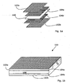
- Figure 1a shows the layers that make up a laminate blank 100 (a 'blank' is an item to be moulded) of Figure 1b according to the present invention.
- the layers comprise two outermost layers 102a, 102b of continuous-fibre unidirectional reinforced polypropylene, an example of what is known in the art as a 'thermoplastic prepreg', wherein the fibres are orientated in a first direction.
- a 'long' fibre in this context, generally means a fibre with a length greater than around 1cm, distinguishing from 'short' fibres of around 0.4mm in length, such as are used to reinforce plastics to be injection moulded.
- fibres of at least four to ten centimetres are suitable (i.e. what would be termed continuous fibres) and the fibres run roughly parallel to the surface of the layers 102a, 102b.
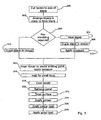
- the layers 102a, 104a, 106, 104b, 102b may generally be provided on rolls and can be pulled out to and cut to the size of the blank 100 in step 300 of the process described in the flowchart of Figure 3 .
- the layers 102a, 104a, 106, 104b, 102b are then placed in a stack to form the blank 100 in step 302.
- each of the outermost fibre reinforced layer 102a, 102b is an inner layer 104a, 104b of continuous-fibre unidirectional reinforced polypropylene, wherein the fibres are orientated in a second direction, roughly orthogonal to the first direction.
- a substrate or core layer 106 comprising 'natural' polypropylene (i.e., the propylene is not reinforced with fibres). This provides a polymer rich core.
- the lay-up of the blank 100 is balanced, in that there are the same number of layers either side of the core and that the layers are organised to form a mirror image in the sense that the order of the layer moving out from the core it the same on both sides (e.g. a layer with fibres in the first direction followed by a layer of fibres in the second direction).
- the next step is to mould the panel.
- the skilled person will appreciate that there are various ways of moulding a panel, of which vacuum consolidation and pressing are briefly discussed below, following some discussion of the prior art.
- the blank 100 is laid into a mould 200a, 200b, 200c allowing sufficient 'drape' to fill the mould 200a, 200b, 200c.
- the blank 100 is heated before being placed in the mould 200a, both so that the layers combine and so that the blank 100 is malleable and will take on the shape of the mould 200a.
- the material will cool slightly in transfer into the mould 200a. The material may not conform entirely to the shape of the mould and a pitted surface may result. This creates a surface which is hard to paint and which may not produce an aesthetically pleasing result.
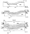
- FIG. 2a A further problem is that fibre reinforced materials tend to 'hold off' in concave corners of moulds.
- An example of this is shown in Figure 2a .
- the material will not readily take the shape of the mould 200a and voids 202, 204 are left between the draped material and the mould 200a. This means that sharp corners in a mould 200a are not reproduced in the moulded panel.
- Figure 2a also illustrates that, the sharper the corner (i.e. the smaller the radius of curvature), the more of a void 202, 204 can be seen.
- step 304 is to consider whether pre-forming is required.
- Pre-forming is generally required when the shape required from the blank 100 is complex or convoluted.
- Pre-forming comprises the steps of heating the blank 100 (generally to less than the melting point of the material) (step 306) (Step 306) draping the blank 100 into a mould 200a (Step 308), 200b, 200c and pressing the blank 100 into the extremities of the mould (step 310). Such pressing can be done with a hand-held tool.
- the blank is laid into the mould at substantially the ambient temperature (step 312).
- the layers are laid up to create the blank 100, the layers are not bonded, or 'consolidated', together and, at approximately the ambient temperature, the blank 100 is placed in a heated mould 200b, 200c as shown in Figures 2b, 2c , in which the outermost layers 102a are shown but the remaining layers are not shown for the sake of clarity.
- a suitable mould 200b, 200c is manufactured by Roctool, of BP341 Savoie Technolac, 73377 Le Bourget You Lac, France.
- the heated vacuum mould 200b of Figure 2b comprises a channel 206 for the introduction of heating or cooling fluids.
- a mould may be heated by electromagnetic inductive process.
- the heated mould 200b has only one surface to which heat is applied.
- a panel is formed when pressed into the mould 200b by a vacuum applied to a vacuum bag.
- the vacuum bag is sealed, a vacuum is applied and the surface of the mould 200b is heated in step 314.
- the material softens and melts to the face of the mould 200b.
- the mould 200b is heated to above the melting point of the material 100.
- the melting point of polypropylene is 170°C
- the mould 200b is heated to 180°C, although in other examples, this may be increase by 30°C to speed the melting process.
- the layers 102a, 104a, 106, 104b, 102a become fully consolidated.
- the tool is heated for around ten minutes to reach the temperature required.
- the composite is then allowed a few minutes (typically five minutes) 'dwell' time within the mould 200b temperature (step 316), where the mould 200b is maintained at 180°C, before cooling for around ten minutes (Step 318) before being removed in step 320), giving an overall cycle time of around thirty minutes for the complete cycle including loading and removal.
- press moulding A faster alternative to vacuum consolidation is press moulding, but as will be appreciated by the skilled person, the tooling-up costs are high as it requires the investment in 'matched' tooling.
- An example of a press mould 200c is shown in Figure 2c .
- the press mould 200c comprises a female part 200ci and a male part 200cii, which are brought together to press a part.
- both the female 200ci and the male 200cii parts incorporate cooling channels 206i, 206ii for the introduction of heating or cooling fluids near the surfaces in contact with the part to me machined.
- a slip frame controls the way that the continuous fibres are allowed to 'slip' into the profile of the mould 200b.
- a slip frame comprises a substantially rectangular frame which holds the edges of a rectangle of material to be pressed, clamping with a predetermined tension provided by springs. The tension is set so that the material is allowed to 'slip' though the frame and into the mould 200c with a predetermined tension.
- a suitable slip frame can be supplied by Elkington Brothers of Birmingham, UK.
- the heating on the mould 200c brings the material up above its melting point (step 306) as described above in relation to vacuum consolidation).
- the blank 100 has a 'dwell' time before the heat on the mould 200c removed (step 316) and the mould 200c cooled.
- the part is then cooled (step 318) to a temperature at which it can safely be removed from the mould 200c (step 320).
- the overall cycle time can be under two minutes.
- the presence of heat at the surface means that the polymer tends to melt and run into any voids between the mould 200b, 200c and the fibres of the outermost layers 102a, 102b.
- Both processes operate at a 'low' pressure of around one bar to ensure that there is minimal fibre movement in the outermost 102a,b and inner layers 104a, b.
- pressures of between roughly one to ten bars may be appropriate.
- the panel is taken from the mould 200b and trimmed as necessary.
- polypropylene if it is to be painted, some pretreatment is required.
- the surface of panel is prepared with flame treatment or plasma gun (step 322) and tested to ensure a surface tension in excess of 40 Dynes/cm, as is required for paint adhesion for a high quality finish.
- Other polymers may not require this treatment or may require another treatment.
- a primer finish is also applied (step 324) to the panel such that a layer of less flexible skin that does not move with the panel forms.
- the primer according to one embodiment of the present invention incorporates a hardening lacquer.
- the resulting primed panel is left to dry before being painted with a coloured paint (step 326). Once this has dried, a topcoat comprising a clear gloss overcoat is applied (step 328).
- the outer layers comprising woven fibre, bi-direction fibre or 'quasi-isotropic' (fibres which run lengthwise, across and on the diagonal) fibre reinforcement, with the core layer as described above.
- the core layer may not comprise natural polypropylene but may instead comprise 'random fibre' reinforced polypropylene or may be a recycled material, (for example, a ground-up car part such as a bumper) with impurities such as paint flecks.
- the layers of the composite may comprise a thermoplastic other than polypropylene, although the skilled person will appreciate that the choice of polymer will have an affect on the process as a whole- treatment temperatures will be different, some of the method steps (in particular, treating the panel prior to painting) will not be necessary.
- pre-treating a moulded part before painting may not be essential for some polymers.
- the method may comprise additional 'in-mould' processes, such as coating with a decorative foil, a facing fabric or an electric circuit.
- the panel has a feature comprising a discontinuation in curvature of the surface may be an optional feature to the invention.
Abstract
Description
- The present invention relates to the field of composite plastics and related manufacturing methods.
- Plastics provide a versatile, convenient material for many products and has, in a great range of applications, replaced materials such as metal or wood. The convenience arises from the malleability of plastics, the fact that it can take on complex shapes, and the durability compared with previously used materials. Further, there is a great range of plastics available, with different characteristics such as melting point, stiffness, density, etc, and as such a suitable plastic can be found for a vast range of applications.
- It will also be appreciated that many types of plastic are recyclable (this applies more to so-called thermo-plastics, which can be re-melted, than to thermosetting plastics). This is particularly beneficial as environmental issues have become important to consumers as well as the subject of considerable legislation. There now exist in various countries incentives to use or produce recyclable products in industry.
- However, it will be appreciated that existing plastics cannot always replicate the properties of other materials. Considering the example of a bonnet of a car, this is required to be strong (to protect the occupants of the car in the event of a collision), resilient (to protect a pedestrian hit in a collision), and also to have a low heat expansion factor (it will be appreciated that the bonnet will be heated by the engine and simply by standing in the sun; it is important that the part does not change shape and size significantly). There are further manufacturing preferences- the part must be paintable, and produced at reasonable cost. It is preferably fairly light-weight (lighter cars are either cheaper to run or better performers than a heavier car of the same design) and easy to mould, both in terms of taking the required shape and in taking the required design details, such as an inset area for a car company's badge.
- In the past, steel, aluminium or thermosetting plastic has been used to manufacture car bonnets, roofs and other like parts. However, the tooling-up costs associated with this method make steel and aluminium undesirable and unsuitable for limited production runs. Thermosetting plastics are not generally recyclable.
- Fibre reinforced sheets are well known in order to provide plastics material with improved mechanical properties. The fabrication of such materials is known from documents such as
US 5 194 462 which describes a method of making a glass matt thermoplastic material in which the reinforcing fibres are arranged in a continuous gradient layer structure wherein the density of fibres is continuously varied through the material from a high density layer to a lower density layer. This process is commonly referred to as a 'film stack' process. Other methods of producing a random fibre matrix in a thermoplastic include the 'The ICI hot tube process', Flexline', 'Bay Mills / Spiflex', 'Radlite' and powder impregnation . -
US 5 866 051 shows a method for making continuous fiber-reinforced plastic composites in which layers are extruded through a die. - According to a first aspect of the invention there is provided a method of producing a panel having at least one feature comprising a discontinuation in curvature of surface in the surface, the method comprising the steps of:
- providing a first reinforced layer of long or continuous parallel fibre reinforced thermoplastic of a first polymer;
- providing a core layer of thermoplastic of a second polymer which is compatible with the first polymer;
- providing a second reinforced layer of long or continuous parallel fibre reinforced thermoplastic of the first polymer;
- stacking the layers such that the reinforced layers are separated by the core layer;
- introducing the stack into a panel mould and heating the mould to at least the melting point of the predetermined polymer to consolidate the layers and form the panel.
- The skilled person will appreciate that the parallel fibres in a layer may run in one direction or more than one direction, for example in woven fibre reinforced material. Further, it should be appreciated that 'compatible' in the sense used above means that the plastic layers melt together. It is likely that compatible polymers have the same polymer base. It will be appreciated that with thermosetting plastics melting of the core and reinforced layers would not occur in the same manner and so thermosetting plastics materials would not be suitable for this method.
- Further, a discontinuity in the curvature of the surface may comprise rounding, for example at the edges of the panel, or may comprise an indentation. In one embodiment, the panel is a car body panel and the indentation may comprise a hollow for a car company's badge or a particular design feature, such as a fin, a vent, ridge, undulation, or the like.
- This may be advantageous as separating the two reinforced layers adds stiffness and strength to the panel which allow the panel to be used in place of steel panels (which are expensive) and thermosetting plastic panels (which cannot easily be recycled). The material may also exhibit qualities of resilience which improve pedestrian safety. The reinforcing fibres act to limit the thermal expansion of the panels, which can therefore be used in part with a high thermal load, such as car roofs or bonnets, which are heated by the sun. Further, the process of heating the mould can result in a smooth surface which can readily be painted. The core provides a polymer rich layer and polymer from this layer can penetrate the reinforced layers in particular in sharp concave corners of a mould to fill voids left between the reinforcing layers and these corners. The skilled person will appreciate that the resulting panel will better follow the shape of the mould. Further, heating the mould allows a low pressure to be used in the moulding process, which means that delicate 'in-mould' processes, such as laying a circuit board, can be performed.
- It will be seen that the method proposed by the application brings together a first reinforced layer of long or continuous parallel fibre reinforced thermoplastic of a first polymer, a core layer and a second reinforced layer of long or continuous parallel fibre reinforced thermoplastic of a first polymer. Each of the layers may be constituted by a commercial product but the hybrid structure produced by the method has advantageous properties as outlined herein which are not achievable from any of the starting materials.
- The core layer may be provided by any suitable material examples of which include random glass reinforced thermoplastic such as 'Azdel' produced by GE Azdel, Southfield MI 48076, USA, or a similar product from Quadrant Composites of Lenzburg, Switzerland.
- The first and second reinforced layers may be provided by a continuous unidirectional fibre reinforced material. Examples of such materials are provided under the trade name Plytron' from Gurit Suprem, CH-8247 Flurlingen, Switzerland, or similar products from Mitsui, Japan. Similar products can be used from a variety of sources. Alternative embodiments may use continuous fibres with a powder coated product, but it is believe that the properties of the finished hybrid structure are not as good.
- Preferably the core layer has at least roughly 70% by volume of the second polymer (i.e. there may be up to roughly 30% of other material in the core layer which would generally be a reinforcing material). Provision of a core layer having generally 70% by volume of the second polymer generally equates to providing a structure in which the volume of the core material is roughly equal to the volume of the material in the reinforced layers.
- Provision of the second polymer to greater than 50% of the sum of the skin materials by volume is thought to be advantageous because it generally provides a core layer which is roughly equal in thickness to the combined thickness of the two reinforced layers. This allows stiffness and dimensional stability to be maintained, whilst improving processability and reducing cost.
- In some embodiments (and depending upon the polymer used), the method further comprises treating the moulded panel with a flame treatment, corona discharge or a plasma gun. As will be familiar to the man skilled in the art, treating a polymer in this way increases the surface tension which can improve paint adhesion.
- As will be understood by the person skilled in the art, 'long-fibre' reinforced thermoplastics are impregnated with fibres- which are commonly glass, carbon, synthetic or natural materials- such that they maintain their shape under varying environmental conditions. The skilled person will appreciate that within the art the term long has a meaning of a fibre having a length of between roughly 1mm and roughly 10mm and that a continuous fibre has a length of any thing over roughly 10mm up to the length of the product in which the fibre is used. Short fibres are recognized as having a length of under roughly 1mm. In a particularly preferred embodiment, the fibres are continuous and therefore may be anywhere between 10mm in length and up to roughly the length of the panel being produced.
- The first and second polymers may be the same, or substantially the same polymer. This is advantageous as such a panel may be readily melted and recycled- a panel incorporating more than one polymer may have unpredictable qualities and therefore its re-use may be limited or prevented.
- The moulding may be performed in a vacuum consolidation mould, a stamp-press mould or any other suitable mould. These provide convenient moulds which are in use in the art.
- In preferred embodiments, the tooling surface (i.e. the surface in contact with the panel) is heated. This may save energy when compared to heating the mould as a whole.
- Further, in preferred embodiments, heat is applied to at least the tooling surface intended to mould a side of the panel to be painted. This is advantageous as the heating process allows the plastic to melt and form a smooth, readily paintable surface.
- The method may further comprise cooling the mould. This may allow the panel to be cooled and therefore processed more quickly than would be possible if the mould was left to cool. The mould may be cooled using a cooling fluid or in some other way. In some embodiments, particularly where only the tooling surface of the mould is heated, only the cooling surface may be cooled. This may reduce the amount of cool fluid required.
- The method may comprise providing the core layer such that it comprises approximately 50% of the depth of the panel. This is convenient as it allows the reinforced layers to be separated by a reasonable amount (as a rule, the greater their separation, the greater the stiffness of the panel). However, in alternative embodiments, the core layer may comprise roughly any of the following: 25%, 40%, 60%, 80% or some value in between.
- In some embodiments, the method may comprise providing more than two reinforced layers. In what is perhaps a preferred embodiment, there are two reinforced layers either side of the core layer, wherein the outermost layers incorporate fibres in a first direction and the inner reinforced layers incorporated fibres in a second direction, orthogonal to the first and the core is disposed between the inner reinforced layers. This may be advantageous as the fibres act to limit thermal expansion in two directions.
- In preferred embodiments, the reinforcing layer(s) to one side of the core layer may be arranged to substantially 'mirror' the reinforcing layer(s) to the other side of the core. This is intended to mean both that the layers are balanced in number either side of the core and also that the orientation of the fibres are mirrored, for example in a 5-layer structure, the outermost layers may comprise longitudinally oriented fibres and the inner reinforced layers may comprise transversely orientated fibres (see
Figure 1 for an example of a 'mirrored' arrangement). This arrangement is advantageous as it prevents distortion. It should be noted that further finish- for example a paint layer or fabric layer- does not upset the balance of the panel. - In further alternative embodiments, the method may comprise providing the reinforced layer(s) with fibres lying in two roughly orthogonal directions. For example layers in the first and second reinforced layers may normally be laid in what is termed a 0° 90° matrix, mirror imaged from the centre/core.
- The layer(s) may additionally or alternatively, comprise fibres lying across the diagonal in what is termed in the art a 'Quasi isotropic' arrangement. In such embodiments, the method may comprise weaving together the fibres before incorporating them into a layer. This may restrict the thermal expansion in various directions with just two layers of reinforced material.
- Additionally, or in alternative embodiments, the method may comprise providing the reinforced layer(s) with fibres laying at angles to one another other than at 90°. In one particularly advantageous embodiment fibres are oriented at roughly 37° to one another. This, in the case of a polypropylene matrix, has been found to be particularly advantageous since it will gives the resultant plastics material thermal expansion properties roughly equal to those of steel. The thermal properties of the resultant plastics material may be matched to other materials by orienting the fibres at other directions to one another.
- The method may comprise providing the core layer with reinforcing fibres. Suitable fibres may be randomly orientated fibres. This may improve the strength of the panel. Alternatively, the core may be provided as a natural, or un-reinforced, material. This may be advantageous as it may improve the malleability of the panel.
- The core may be made up of recycled material, for example ground-up plastic parts. In one example, a bumper may be recycled. As will be appreciated by the person skilled in the art, bumper material does not generally include fibre reinforcement, but there is a 'filler', normally a synthetic rubber that improves impact performance and paint adhesion). The bumper may also be painted. The ground bumper may be regarded as a filled grade with paint particles also acting as a filler in the ground material. It has previously been considered that such recycled material cannot be used in manufacturing panel which are required to be strong. This is because the impurities such as paint flecks cause discontinuities in the structure, which is then prone to fracture about those points. However, under the present arrangement, the strength is provided by the reinforced layers and the recycled material may be used without the need to strip the part of paint or remove other impurities first.
- The core layer could also be formed from industrial regrind (e.g. from a fibre manufacturer) or end of use recycling (e.g. packaging).
- The method may comprise using the panel in the manufacture of a vehicle. The panel may for example provide the bonnet, roof or boot of a car. Alternatively, it may provide a panel for an aircraft door or body part.
- According to a second aspect of the invention there is provided a panel formed of laminate composite material having at least one feature comprising a discontinuation in curvature of surface in the surface and further comprising a core of thermoplastic which comprises a first polymer and the panel further comprising cover layers comprising long fibre reinforced thermoplastic of a second polymer, wherein the long fibres are oriented parallel to the surface of the cover layers and the core layer is at least partly covered on each surface by one of the cover layers, wherein the layers are consolidated in a heated mould.
- Preferably, the material is arranged such that when heat is applied to the cover layer, polymer from the core will be drawn towards the surface(s) of the cover layers.
- This may be advantageous as it provides a smooth surface which is easy to paint.
- In some embodiments the first and second polymers are the same or substantially the same.
- Preferably, the stack comprises at least three layers, the two outer layers comprising continuous fibre reinforced thermoplastic of the common polymer and at least one inner layer comprising an unreinforced or random fibre reinforced thermoplastic of the common polymer.
- The layers may have been consolidated in a vacuum consolidation mould or by stamping. These are convenient methods of forming a panel which are in use in the art.
- Thus, the panel may provide a composite plastic comprising at least one inner layer of thermoplastic of a predetermined polymer and further comprising at least two cover layers of long or continuous fibre reinforced thermoplastic of the predetermined polymer, wherein the long or continuous fibres are oriented substantially parallel to the surface of the cover layers and the inner layer is generally covered on each surface by a cover layer.
- Such a composite plastic may be advantageous as the cover layers may enable a sample of the composite to maintain its shape under different environmental conditions and the inner layer may provide increased malleability.
- In a particularly preferred embodiment the fibres in the cover layers are continuous.
- The panel may be painted by applying a first layer of primer paint which is thixotropic, allowing the first layer to form a rigid coating and applying a second layer of paint.
- This may be advantageous as composite laminate plastic panels may comprise outer layers reinforced with fibres, which may be glass, carbon, natural or synthetic fibres. Such panels will, when subjected to changes in temperature due, for example, to standing in the sun, be subject to changes in thickness under thermal expansion and contraction. On expansion, a paint layer may be pushed up and may remain in that position following contraction. This can result in 'witness marks', in particular of the fibres, being left in the paint finish over time.
- In some embodiments, the plastic may comprise a composite plastic. In such embodiments, the composite may comprise at least three layers, the two outer layers comprising a long and/or continuous fibre reinforced thermoplastic of the common polymer and at least one inner layer comprising an unreinforced or random fibre reinforced thermoplastic of the common polymer.
- This method may be particularly advantageous in the case of a panel formed from a stack of at least three layers, the two outer layers comprising a long and/or continuous fibre reinforced thermoplastic of the common polymer and at least one core layer comprising a thermoplastic of the common polymer. Although such a panel may have desirable strength and heat expansion properties, the long fibres may be particularly prone to leaving witness marks. Such a primer layer can help to seal the surface such that changes in thickness may not be perceptible by the naked eye.
- The method may further comprise providing the second layer of paint as a coloured layer. This is convenient as it allows a coloured panel to be produced.
- The method may further comprise providing a layer of clear gloss coat. This may be advantageous as it provides a high quality finish which is durable an visually pleasing.
- As will be appreciated by the man skilled in the art, features described in relation to one of the aspects of invention described above may equally apply to other aspects.
- Embodiments of the invention are now described by way of example only and with reference to the accompanying Figures of which:
-
Figure 1a shows a five layer composite before the layers are bonded; -
Figure 1b shows a 'blank' formed from the five layer composite ofFigure 1a ; -
Figure 2a shows a panel being formed in a mould according to a prior art process; -
Figure 2b shows a panel being formed in a vacuum mould according to one embodiment of the present invention; -
Figure 2c shows a panel being formed in a press mould according to one embodiment of the present invention; -
Figure 3 shows a flow chart of a process according to one embodiment of the present invention; - The present example relates to providing a car panel with a high quality painted finish.
Figure 1a shows the layers that make up a laminate blank 100 (a 'blank' is an item to be moulded) ofFigure 1b according to the present invention. The layers comprise twooutermost layers layers - The
layers step 300 of the process described in the flowchart ofFigure 3 . Thelayers step 302. - Inside each of the outermost fibre reinforced
layer inner layer - Between the
inner layers core layer 106 comprising 'natural' polypropylene (i.e., the propylene is not reinforced with fibres). This provides a polymer rich core. - The lay-up of the blank 100 is balanced, in that there are the same number of layers either side of the core and that the layers are organised to form a mirror image in the sense that the order of the layer moving out from the core it the same on both sides (e.g. a layer with fibres in the first direction followed by a layer of fibres in the second direction).
- The next step is to mould the panel. The skilled person will appreciate that there are various ways of moulding a panel, of which vacuum consolidation and pressing are briefly discussed below, following some discussion of the prior art.
- The blank 100 is laid into a
mould mould mould 200a, both so that the layers combine and so that the blank 100 is malleable and will take on the shape of themould 200a. However, the material will cool slightly in transfer into themould 200a. The material may not conform entirely to the shape of the mould and a pitted surface may result. This creates a surface which is hard to paint and which may not produce an aesthetically pleasing result. - A further problem is that fibre reinforced materials tend to 'hold off' in concave corners of moulds. An example of this is shown in
Figure 2a . The material will not readily take the shape of themould 200a and voids 202, 204 are left between the draped material and themould 200a. This means that sharp corners in amould 200a are not reproduced in the moulded panel.Figure 2a also illustrates that, the sharper the corner (i.e. the smaller the radius of curvature), the more of a void 202, 204 can be seen. - The next stage in the process according to one embodiment of the present invention,
step 304, is to consider whether pre-forming is required. Pre-forming is generally required when the shape required from the blank 100 is complex or convoluted. Pre-forming comprises the steps of heating the blank 100 (generally to less than the melting point of the material) (step 306) (Step 306) draping the blank 100 into amould 200a (Step 308), 200b, 200c and pressing the blank 100 into the extremities of the mould (step 310). Such pressing can be done with a hand-held tool. - Alternatively, where no performing is required, the blank is laid into the mould at substantially the ambient temperature (step 312).
- According to this embodiment of the present example although the layers are laid up to create the blank 100, the layers are not bonded, or 'consolidated', together and, at approximately the ambient temperature, the blank 100 is placed in a
heated mould 200b, 200c as shown inFigures 2b, 2c , in which theoutermost layers 102a are shown but the remaining layers are not shown for the sake of clarity. Asuitable mould 200b, 200c is manufactured by Roctool, of BP341 Savoie Technolac, 73377 Le Bourget You Lac, France. - The case of vacuum consolidation is considered first. The
heated vacuum mould 200b ofFigure 2b comprises achannel 206 for the introduction of heating or cooling fluids. In alternative embodiments, a mould may be heated by electromagnetic inductive process. - Where vacuum consolidation is used, the
heated mould 200b has only one surface to which heat is applied. As will be familiar to the person skilled in the art, a panel is formed when pressed into themould 200b by a vacuum applied to a vacuum bag. - In vacuum consolidation, once the blank 100 has been draped into the mould 100b, the vacuum bag is sealed, a vacuum is applied and the surface of the
mould 200b is heated instep 314. The material softens and melts to the face of themould 200b. Themould 200b is heated to above the melting point of thematerial 100. Under the present example, as the melting point of polypropylene is 170°C, themould 200b is heated to 180°C, although in other examples, this may be increase by 30°C to speed the melting process. - Once the composite has reached 180°C through to the core, the
layers mould 200b temperature (step 316), where themould 200b is maintained at 180°C, before cooling for around ten minutes (Step 318) before being removed in step 320), giving an overall cycle time of around thirty minutes for the complete cycle including loading and removal. - A faster alternative to vacuum consolidation is press moulding, but as will be appreciated by the skilled person, the tooling-up costs are high as it requires the investment in 'matched' tooling. An example of a press mould 200c is shown in
Figure 2c . - The press mould 200c comprises a female part 200ci and a male part 200cii, which are brought together to press a part. In the embodiment here described, both the female 200ci and the male 200cii parts incorporate
cooling channels 206i, 206ii for the introduction of heating or cooling fluids near the surfaces in contact with the part to me machined. - In press moulding, once the blank 100 has been loaded into the mould 200c, which is sometimes referred to as a 'tool' in this context, and the mould 200c is heated and closed in
step 314. A slip frame controls the way that the continuous fibres are allowed to 'slip' into the profile of themould 200b. As will be understood by those skilled in the art, a slip frame comprises a substantially rectangular frame which holds the edges of a rectangle of material to be pressed, clamping with a predetermined tension provided by springs. The tension is set so that the material is allowed to 'slip' though the frame and into the mould 200c with a predetermined tension. A suitable slip frame can be supplied by Elkington Brothers of Birmingham, UK. Once the blank has been laid into the mould 200c, and as the mould 200c closes, the heating on the mould 200c brings the material up above its melting point (step 306) as described above in relation to vacuum consolidation). The blank 100 has a 'dwell' time before the heat on the mould 200c removed (step 316) and the mould 200c cooled. The part is then cooled (step 318) to a temperature at which it can safely be removed from the mould 200c (step 320). The overall cycle time can be under two minutes. - In both pressing and vacuum consolidation, the presence of heat at the surface means that the polymer tends to melt and run into any voids between the
mould 200b, 200c and the fibres of theoutermost layers - Both processes operate at a 'low' pressure of around one bar to ensure that there is minimal fibre movement in the outermost 102a,b and
inner layers 104a, b. In alternative embodiments, pressures of between roughly one to ten bars may be appropriate. - The panel is taken from the
mould 200b and trimmed as necessary. In the present example of polypropylene, if it is to be painted, some pretreatment is required. The surface of panel is prepared with flame treatment or plasma gun (step 322) and tested to ensure a surface tension in excess of 40 Dynes/cm, as is required for paint adhesion for a high quality finish. Other polymers may not require this treatment or may require another treatment. - Whilst it will be understood that the thermal expansion of the panel has been reduced by the inclusion of fibre reinforcement, there is still thermal expansion in the thickness of the panel described caused by changed in the temperature of the environment, which remains unrestricted by fibres. Thermal expansion does also occur but to a much lesser degree compared to the same polymer but with not reinforcing. Unless preventative action is taken, this movement is however sufficient to allow a so-called 'witness' of the fibre reinforcement to show in the surface aspect. A 'witness' is seen when the panel has expanded and the paint moved with it, but the paint returns to it original position on cooling. This effect can leave a 'witless' of the fibres in the paint finish. It will be appreciate by the man skilled in the art that a paint finish for a car will be subjected to standard climatic cycle tests before it is used on a car and such test will demonstrate this effect.
- However, under the present example, a primer finish is also applied (step 324) to the panel such that a layer of less flexible skin that does not move with the panel forms. The primer according to one embodiment of the present invention incorporates a hardening lacquer.
- The resulting primed panel is left to dry before being painted with a coloured paint (step 326). Once this has dried, a topcoat comprising a clear gloss overcoat is applied (step 328).
- It will be appreciated the example described herein has particular application where large horizontal panels such as bonnets, roofs and boots as these are subjected to a high thermal load from the sun.
- In alternative embodiments, which are to be considered within the scope of the present invention, there may be only three layers- the outer layers comprising woven fibre, bi-direction fibre or 'quasi-isotropic' (fibres which run lengthwise, across and on the diagonal) fibre reinforcement, with the core layer as described above. Alternatively, the core layer may not comprise natural polypropylene but may instead comprise 'random fibre' reinforced polypropylene or may be a recycled material, (for example, a ground-up car part such as a bumper) with impurities such as paint flecks. Indeed, the layers of the composite may comprise a thermoplastic other than polypropylene, although the skilled person will appreciate that the choice of polymer will have an affect on the process as a whole- treatment temperatures will be different, some of the method steps (in particular, treating the panel prior to painting) will not be necessary.
- Further, pre-treating a moulded part before painting may not be essential for some polymers.
- The method may comprise additional 'in-mould' processes, such as coating with a decorative foil, a facing fabric or an electric circuit.
- The fact that the panel has a feature comprising a discontinuation in curvature of the surface may be an optional feature to the invention.
Claims (25)
- A method of producing a panel having at least one feature comprising a discontinuation in curvature of surface in the surface, the method comprising the steps of:providing a first reinforced layer (102a) of long and/or continuous parallel fibre reinforced thermoplastic of a first polymer;providing a core layer (106) of thermoplastic of a second polymer which is compatible with the first polymer;providing a second reinforced layer (102b) of long or continuous parallel fibre reinforced thermoplastic of the first polymer;stacking the layers such that the reinforced layers are separated by the core layer (106);introducing the stack into a panel mould and heating the mould to at least the melting point of the predetermined polymer to consolidate the layers and form the panel.
- A method according to claim 1 in which the core (106) material has at least one of the following: i. roughly 70% by volume of the second polymer and ii. roughly an equal volume as the two reinforced layers.
- A method of producing a panel according to claim 1 or 2 which further comprises treating the moulded panel with a flame treatment, corona discharge or a plasma gun.
- A method of producing a panel according to any preceding claim in which are the first and second polymers are the same, or substantially the same polymer.
- A method of producing a panel according to any preceding claim in which the moulding is performed in a vacuum consolidation mould or a stamp-press mould.
- A method of producing a panel according to any preceding claim in which at least a portion of the mould (200a, b, c) is heated.
- A method of producing a panel according to claim 6 in which at least a tooling surface intended to mould a side of the panel to be painted is heated.
- A method of producing a panel according to any preceding claim which further comprises cooling at least a portion of the mould.
- A method of producing a panel according to claim 8 in which only the tooling surface is cooled.
- A method of producing a panel according to any preceding claim which comprises providing the core layer (106) such that it comprises approximately 50% of the depth of the panel.
- A method of producing a panel according to any preceding claim comprises providing more than two reinforced layers (102a, b).
- A method of producing a panel according to claim 11 which comprises providing two reinforced layers (102a,b, 104a,b) either side of the core layer (106), wherein the outermost layers incorporate fibres (102ab) in a first direction and the inner reinforced layers (104a,b) incorporated fibres in a second direction, orthogonal to the first or lying across the diagonal in a quasi-isotropic arrangement and the core (106) is disposed between the inner reinforced layers.
- A method of producing a panel according to any preceding claim in which the reinforcing layer(s) (102a, 104a) to one side of the core layer are arranged to substantially mirror the reinforcing layer(s) to the other side (102b, 104b) of the core (106).
- A method of producing a panel according to any preceding claim which comprises providing the reinforced layer(s) with fibres lying in two orthogonal directions and/or the layer(s) additionally comprise fibres lying across the diagonal in a Quasi isotropic arrangement.
- A method of producing a panel according to claim 14 which comprises weaving together the fibres before incorporating them into a layer.
- A method of producing a panel according to any preceding claim which comprises providing the core (106) layer with reinforcing fibres.
- A method of producing a panel according to any preceding claim in which the core (106) includes recycled material, industrial regrind or end of use recycling.
- A method of producing a panel according to any preceding claim which comprises using the panel in the manufacture of a vehicle.
- A panel formed of laminate composite material having at least one feature comprising a discontinuation in curvature of surface in the surface and further comprising a core (106) of thermoplastic which comprises a first polymer and the panel further comprising cover layers (102a, 102b) comprising long fibre reinforced thermoplastic of a second polymer, wherein the long fibres are oriented parallel to the surface of the cover layers (102a, 102b) and the core layer (106) is at least partly covered on each surface by one of the cover layers (102a, 102b), wherein the layers are consolidated in a heated mould.
- A panel according to claim 19 where the first and second polymers are the same, or substantially the same polymer.
- A panel according to claim 20 in which the stack comprises at least three layers, the two outer layers (102a, 102b) comprising a long or continuous fibre reinforced thermoplastic of the common polymer and at least one core layer (106) comprising an unreinforced thermoplastic of the predetermined polymer.
- A panel according to any of claims 19 to 21 in which the core layer (106) comprises at least one of 70% by volume of the first polymer and 50% by volume of the panel.
- A panel according to any of claims 19 to 22 comprising two additional reinforced layers, the layers (102a,b, 104a,b) being arranged such that two reinforced layers are on either side of the core layer (106) wherein the outermost layers (102a,b) incorporate fibres in a first direction and the inner reinforced layers (104a,b) incorporate fibres in a second direction, orthogonal to the first or lying across the diagonal in a quasi-isotropic arrangement and the core is disposed between the inner reinforced layers.
- A panel according to any of claims 19-23 where the reinforcing layer(s) to one side of the core layer substantially mirror the reinforcing layer(s) to the other side of the core (106).
- A panel according to any of claims 19-24 where the reinforced layer(s) have fibres lying in two orthogonal directions and/or the layer(s) additionally comprise fibres lying across the diagonal in a quasi-isotropic arrangement wherein the fibres in a layer may be woven together.
Applications Claiming Priority (3)
| Application Number | Priority Date | Filing Date | Title |
|---|---|---|---|
| GB0416197A GB0416197D0 (en) | 2004-07-20 | 2004-07-20 | Composite plastic and related manufacturing methods |
| GB0416198A GB0416198D0 (en) | 2004-07-20 | 2004-07-20 | Composite plastic and related manufacturing methods |
| PCT/GB2005/002857 WO2006008529A1 (en) | 2004-07-20 | 2005-07-20 | Recyclable composite plastic for automotive headliner |
Publications (2)
| Publication Number | Publication Date |
|---|---|
| EP1773587A1 EP1773587A1 (en) | 2007-04-18 |
| EP1773587B1 true EP1773587B1 (en) | 2012-04-04 |
Family
ID=34975229
Family Applications (1)
| Application Number | Title | Priority Date | Filing Date |
|---|---|---|---|
| EP05767925A Not-in-force EP1773587B1 (en) | 2004-07-20 | 2005-07-20 | Recyclable composite plastic and related manufacturing methods |
Country Status (5)
| Country | Link |
|---|---|
| US (2) | US8021595B2 (en) |
| EP (1) | EP1773587B1 (en) |
| JP (1) | JP4812760B2 (en) |
| AT (1) | ATE552109T1 (en) |
| WO (1) | WO2006008529A1 (en) |
Families Citing this family (24)
| Publication number | Priority date | Publication date | Assignee | Title |
|---|---|---|---|---|
| USRE44893E1 (en) | 2004-03-26 | 2014-05-13 | Hanwha Azdel, Inc. | Fiber reinforced thermoplastic sheets with surface coverings |
| US8597562B2 (en) | 2006-03-30 | 2013-12-03 | GM Global Technology Operations LLC | Composite products and methods of making the same |
| US8568853B2 (en) * | 2007-12-14 | 2013-10-29 | Hanwha Azdel, Inc. | Lightweight thermoplastic composite including bi-directional fiber tapes |
| DE102009020190B3 (en) * | 2009-05-07 | 2010-09-09 | Eads Deutschland Gmbh | Device for shaping a workpiece |
| US10000026B2 (en) * | 2011-04-08 | 2018-06-19 | The Boeing Company | Composite induction consolidation apparatus and method |
| JP5712857B2 (en) * | 2011-08-09 | 2015-05-07 | トヨタ自動車株式会社 | Manufacturing method of fiber reinforced resin material |
| CN103568396A (en) * | 2012-08-02 | 2014-02-12 | 上海杰事杰新材料(集团)股份有限公司 | Light-weight and high-strength thermoplastic composite material sandwich board and production method thereof |
| CN103726608A (en) * | 2012-10-12 | 2014-04-16 | 辽宁辽杰科技有限公司 | Sandwich sheet and making method thereof |
| KR102197486B1 (en) * | 2012-12-07 | 2020-12-31 | 한화 아즈델 인코포레이티드 | Articles including untwisted fibers and methods of using them |
| US9375893B2 (en) | 2013-03-14 | 2016-06-28 | Basf Se | Automotive panels |
| CN103410308B (en) * | 2013-06-28 | 2017-02-08 | 句容市百事特复合材料有限公司 | Plastic formwork of LFT material strip fabric reinforcing core layer and producing method thereof |
| DE102013213711A1 (en) * | 2013-07-12 | 2015-01-15 | Brose Fahrzeugteile Gmbh & Co. Kommanditgesellschaft, Hallstadt | Method for producing a structural component for motor vehicles from an organic sheet |
| FR3020777B1 (en) * | 2014-05-09 | 2017-01-20 | Plastic Omnium Cie | STACKING OF REINFORCED PLASTIC MATERIAL LAYERS FOR MOLDING WORKPIECES |
| US10647084B2 (en) * | 2014-11-25 | 2020-05-12 | The Boeing Company | Multi-layer plies for improved composite performance |
| DE102016221481B4 (en) * | 2016-11-02 | 2021-09-16 | Siemens Healthcare Gmbh | Radiation detector with an intermediate layer |
| JP2018162383A (en) * | 2017-03-27 | 2018-10-18 | 三菱ケミカル株式会社 | Fiber-reinforced resin material for use in impact resistant automotive outer panel |
| JP6836489B2 (en) | 2017-09-27 | 2021-03-03 | 本田技研工業株式会社 | Fiber reinforced resin molded product and its manufacturing method, and mold equipment for obtaining it |
| KR102340130B1 (en) * | 2017-12-20 | 2021-12-15 | (주)엘엑스하우시스 | Sandwich panel comprising a fiber reinforced composite material as surface layers |
| EP3802074B1 (en) * | 2018-06-07 | 2021-12-29 | Teijin Carbon Europe GmbH | Multiaxial product having at least two 0° layers |
| JP7030622B2 (en) * | 2018-06-11 | 2022-03-07 | 日産自動車株式会社 | Composite material structure and its formation method |
| AT521251B1 (en) | 2018-11-15 | 2019-12-15 | Raiffeisenlandesbank Oberoesterreich Ag | Cooling device for battery cells assembled into a module |
| KR102470704B1 (en) * | 2018-12-19 | 2022-11-28 | (주)엘엑스하우시스 | Sheet |
| JP2023520592A (en) * | 2020-04-06 | 2023-05-17 | 帝人株式会社 | Vehicle component unit and method for manufacturing vehicle component unit |
| CN114083811A (en) * | 2021-10-20 | 2022-02-25 | 山东非金属材料研究所 | Integrated forming method for multi-surface complex composite shell containing boss |
Citations (1)
| Publication number | Priority date | Publication date | Assignee | Title |
|---|---|---|---|---|
| US5104718A (en) * | 1989-02-28 | 1992-04-14 | Mitsubishi Rayon Co., Ltd. | Prepreg and process for producing the same |
Family Cites Families (40)
| Publication number | Priority date | Publication date | Assignee | Title |
|---|---|---|---|---|
| US1444478A (en) | 1923-02-06 | Calculating machine | ||
| US3179782A (en) * | 1962-02-07 | 1965-04-20 | Matvay Leo | Plasma flame jet spray gun with a controlled arc region |
| DE1454988A1 (en) | 1965-05-03 | 1969-05-08 | Basf Ag | Process for the production of molded articles made of thermoplastics reinforced with fibrous substances |
| DE2534188C2 (en) | 1975-07-31 | 1990-08-23 | Basf Ag, 6700 Ludwigshafen | Molded parts with smooth surfaces made of glass fiber reinforced plastics |
| JPS55113470A (en) | 1979-02-22 | 1980-09-02 | Hasegawa Kagaku Kogyo Kk | Preparation of frp sheet for reinforcing racket frame |
| ATE179358T1 (en) | 1981-01-21 | 1999-05-15 | Kawasaki Chem Holding | GRANULES MADE OF FIBER REINFORCED COMPOSITES AND THEIR PRODUCTION PROCESS |
| IE56901B1 (en) | 1982-03-09 | 1992-01-29 | Wiggins Teape Group Ltd | Method of providing a moulded or mouldable fibre reinforced thermoplastics material |
| GB8400290D0 (en) | 1984-01-06 | 1984-02-08 | Wiggins Teape Group Ltd | Fibre reinforced plastics structures |
| DE3535272C2 (en) | 1985-10-03 | 1995-04-13 | Basf Ag | Semi-finished product made of a textile fabric impregnated with a thermoplastic |
| JPS6360743A (en) | 1986-09-02 | 1988-03-16 | 東レ株式会社 | Light-weight composite material |
| JPS63212517A (en) | 1987-03-02 | 1988-09-05 | Teijin Ltd | Manufacture of composite material |
| US4729917A (en) | 1986-10-24 | 1988-03-08 | Sackner Products Inc. | Method and laminate for thermoforming automobile headliners and like three dimensional objects |
| JPH071837B2 (en) * | 1987-09-04 | 1995-01-11 | 宇部興産株式会社 | Electromagnetic wave absorber |
| US4851167A (en) * | 1987-09-14 | 1989-07-25 | Clint, Inc. | Molding process and apparatus |
| DE3741669A1 (en) | 1987-12-09 | 1989-06-22 | Basf Ag | FIBER REINFORCED, THERMOPLASTIC SEMI-FINISHED PRODUCTS |
| WO1991000796A1 (en) | 1989-07-10 | 1991-01-24 | Ube-Nitto Kasei Co., Ltd. | Stampable sheet made of fiber-reinforced thermoplastic resin and molded article thereof |
| JPH03127668A (en) | 1989-10-13 | 1991-05-30 | Nissan Motor Co Ltd | Method for applying sheeny coating |
| JPH0531811A (en) | 1991-07-26 | 1993-02-09 | Sekisui Chem Co Ltd | Manufacture of fiber-reinforeced resin molded product |
| KR970010445B1 (en) | 1992-05-08 | 1997-06-26 | 게이츠 폼드-파이버 프로덕츠, 인코오포레이티드 | Improved nonwoven moldable composite and method of manufacture |
| US5536532A (en) | 1992-11-13 | 1996-07-16 | Oaks; Robert E. | Painted polyvinyl chloride articles and process for producing the same |
| AU7574694A (en) | 1993-10-15 | 1995-05-04 | Hoover Universal Inc. | Composite fiber material member utilizing reclaimed plastic |
| CA2135322C (en) * | 1993-11-10 | 2001-02-06 | Hiroshi Sugahara | Method for producing a fiber-reinforced thermoplastic resin foamed product |
| JPH08101A (en) | 1994-06-16 | 1996-01-09 | Kubota Corp | Rush seedling raising equipment |
| JPH081081A (en) | 1994-06-20 | 1996-01-09 | Kanto Auto Works Ltd | Coating method of resin bumper |
| TW354280B (en) | 1994-08-04 | 1999-03-11 | Teijin Ltd | Material of a composite molded article of a fiber-reinforced resin of foamed core sandwichded layer and preparation thereof |
| DE4429599A1 (en) | 1994-08-20 | 1996-02-22 | Basf Ag | Rigid fiber composite |
| DE69612798T2 (en) | 1995-03-01 | 2001-08-30 | Kawasaki Steel Co | COMPRESSIBLE FILM PRODUCED BY PAPER PRODUCTION TECHNOLOGY AND METHOD FOR PRODUCING COMPRESSED FILMS WITH A LOW WEIGHT |
| DE19520477A1 (en) | 1995-06-03 | 1996-12-19 | Danubia Petrochem Deutschland | Fibre-reinforced, thermally expanded thermoplastic sheet |
| DE19540950A1 (en) * | 1995-11-03 | 1997-05-07 | Bayer Ag | Polyurethane moldings produced using recycled polyols, a process for their production and their use |
| US5868890A (en) | 1996-11-22 | 1999-02-09 | Eften, Inc. | Process for bonding a cover to a substrate |
| US5866051A (en) * | 1997-04-23 | 1999-02-02 | Industrial Technology Research Institute | Method of making continuous glass fiber-reinforced thermoplastic foam sandwich composites |
| DE19914327A1 (en) | 1998-03-30 | 1999-10-14 | Menzolit Fibron Gmbh | Sandwich board for the construction and vehicle and shipbuilding industries |
| AU4429599A (en) | 1998-06-12 | 1999-12-30 | Avery Dennison Corporation | Multilayered thermoplastic film and sign cutting method using the same |
| CN1120775C (en) | 1998-10-12 | 2003-09-10 | 日东纺绩株式会社 | Reinforcing fiber base for composite material |
| GB2364957B (en) | 1998-11-06 | 2003-06-04 | Structural Polymer Systems Ltd | Moulding materials |
| DE10114553A1 (en) | 2001-03-24 | 2002-09-26 | Quadrant Plastic Composites Ag | Continuous production of glass mat reinforced thermoplastic sheet for molding automotive components involves laying down thermoplastic and reinforcing fibers to a fleece, heating and consolidating |
| DE60208358T2 (en) | 2001-05-09 | 2006-09-28 | Structural Polymer Systems Ltd., Newport | MOLDING WITH VENTILATION STRUCTURE FOR INCLUDED GASES |
| US20030175520A1 (en) * | 2002-03-13 | 2003-09-18 | Grutta James T. | Formed composite structural members and methods and apparatus for making the same |
| DE10237694A1 (en) | 2002-08-15 | 2004-03-04 | Sai Automotive Sal Gmbh | To shape fiber mats, as cladding for automobile interiors, layers of mats together with a polymer film are shaped with heat in a press so that the film melts and impregnates the mat layers |
| US20050153120A1 (en) | 2004-01-14 | 2005-07-14 | General Electric Company | Multilayer product made out of a substrate and on either side at least one cover layer; process for the manufacture of a multilayer product and painted multilayer product and process for painting a multilayer product |
-
2005
- 2005-07-20 JP JP2007522022A patent/JP4812760B2/en not_active Expired - Fee Related
- 2005-07-20 US US11/572,297 patent/US8021595B2/en not_active Expired - Fee Related
- 2005-07-20 WO PCT/GB2005/002857 patent/WO2006008529A1/en active Application Filing
- 2005-07-20 AT AT05767925T patent/ATE552109T1/en active
- 2005-07-20 EP EP05767925A patent/EP1773587B1/en not_active Not-in-force
-
2011
- 2011-08-12 US US13/208,701 patent/US20120021166A1/en not_active Abandoned
Patent Citations (1)
| Publication number | Priority date | Publication date | Assignee | Title |
|---|---|---|---|---|
| US5104718A (en) * | 1989-02-28 | 1992-04-14 | Mitsubishi Rayon Co., Ltd. | Prepreg and process for producing the same |
Also Published As
| Publication number | Publication date |
|---|---|
| US8021595B2 (en) | 2011-09-20 |
| ATE552109T1 (en) | 2012-04-15 |
| JP2008506562A (en) | 2008-03-06 |
| US20120021166A1 (en) | 2012-01-26 |
| WO2006008529A1 (en) | 2006-01-26 |
| JP4812760B2 (en) | 2011-11-09 |
| US20080233342A1 (en) | 2008-09-25 |
| EP1773587A1 (en) | 2007-04-18 |
Similar Documents
| Publication | Publication Date | Title |
|---|---|---|
| EP1773587B1 (en) | Recyclable composite plastic and related manufacturing methods | |
| US9770849B2 (en) | Method of making a sandwich-type, compression-molded, composite component having improved surface appearance | |
| US9707725B2 (en) | Method of making a sandwich-type, compression-molded, composite component having a cellulose-based core and improved surface appearance | |
| EP2855123B1 (en) | Press moulding method | |
| CN112969575B (en) | High strength low heat release composite | |
| DE102011118980A1 (en) | Method for manufacturing outer module having outer planking for modularly constructed housing component, particularly door or casing component of motor vehicle, involves providing thermoplastic fiber reinforced plastic inner shell | |
| EP1015297B1 (en) | Exterior autobody part of reinforced plastic, and arrangement and method for its forming | |
| EP1507646B1 (en) | A method of producing a three-dimensional article having a sandwich structure | |
| Weager et al. | Development of recyclable self-reinforced polypropylene parts for automotive applications | |
| Schmachtenberg et al. | In-mould decorating of continuous-fibre reinforced thermoplastics |
Legal Events
| Date | Code | Title | Description |
|---|---|---|---|
| PUAI | Public reference made under article 153(3) epc to a published international application that has entered the european phase |
Free format text: ORIGINAL CODE: 0009012 |
|
| 17P | Request for examination filed |
Effective date: 20070214 |
|
| AK | Designated contracting states |
Kind code of ref document: A1 Designated state(s): AT BE BG CH CY CZ DE DK EE ES FI FR GB GR HU IE IS IT LI LT LU LV MC NL PL PT RO SE SI SK TR |
|
| DAX | Request for extension of the european patent (deleted) | ||
| 17Q | First examination report despatched |
Effective date: 20090420 |
|
| GRAP | Despatch of communication of intention to grant a patent |
Free format text: ORIGINAL CODE: EPIDOSNIGR1 |
|
| GRAC | Information related to communication of intention to grant a patent modified |
Free format text: ORIGINAL CODE: EPIDOSCIGR1 |
|
| GRAJ | Information related to disapproval of communication of intention to grant by the applicant or resumption of examination proceedings by the epo deleted |
Free format text: ORIGINAL CODE: EPIDOSDIGR1 |
|
| GRAP | Despatch of communication of intention to grant a patent |
Free format text: ORIGINAL CODE: EPIDOSNIGR1 |
|
| GRAS | Grant fee paid |
Free format text: ORIGINAL CODE: EPIDOSNIGR3 |
|
| GRAA | (expected) grant |
Free format text: ORIGINAL CODE: 0009210 |
|
| AK | Designated contracting states |
Kind code of ref document: B1 Designated state(s): AT BE BG CH CY CZ DE DK EE ES FI FR GB GR HU IE IS IT LI LT LU LV MC NL PL PT RO SE SI SK TR |
|
| REG | Reference to a national code |
Ref country code: GB Ref legal event code: FG4D |
|
| REG | Reference to a national code |
Ref country code: CH Ref legal event code: EP |
|
| REG | Reference to a national code |
Ref country code: AT Ref legal event code: REF Ref document number: 552109 Country of ref document: AT Kind code of ref document: T Effective date: 20120415 |
|
| REG | Reference to a national code |
Ref country code: IE Ref legal event code: FG4D |
|
| REG | Reference to a national code |
Ref country code: DE Ref legal event code: R096 Ref document number: 602005033506 Country of ref document: DE Effective date: 20120531 |
|
| REG | Reference to a national code |
Ref country code: NL Ref legal event code: VDEP Effective date: 20120404 |
|
| REG | Reference to a national code |
Ref country code: AT Ref legal event code: MK05 Ref document number: 552109 Country of ref document: AT Kind code of ref document: T Effective date: 20120404 |
|
| LTIE | Lt: invalidation of european patent or patent extension |
Effective date: 20120404 |
|
| PG25 | Lapsed in a contracting state [announced via postgrant information from national office to epo] |
Ref country code: LT Free format text: LAPSE BECAUSE OF FAILURE TO SUBMIT A TRANSLATION OF THE DESCRIPTION OR TO PAY THE FEE WITHIN THE PRESCRIBED TIME-LIMIT Effective date: 20120404 Ref country code: FI Free format text: LAPSE BECAUSE OF FAILURE TO SUBMIT A TRANSLATION OF THE DESCRIPTION OR TO PAY THE FEE WITHIN THE PRESCRIBED TIME-LIMIT Effective date: 20120404 Ref country code: PL Free format text: LAPSE BECAUSE OF FAILURE TO SUBMIT A TRANSLATION OF THE DESCRIPTION OR TO PAY THE FEE WITHIN THE PRESCRIBED TIME-LIMIT Effective date: 20120404 Ref country code: SI Free format text: LAPSE BECAUSE OF FAILURE TO SUBMIT A TRANSLATION OF THE DESCRIPTION OR TO PAY THE FEE WITHIN THE PRESCRIBED TIME-LIMIT Effective date: 20120404 Ref country code: IS Free format text: LAPSE BECAUSE OF FAILURE TO SUBMIT A TRANSLATION OF THE DESCRIPTION OR TO PAY THE FEE WITHIN THE PRESCRIBED TIME-LIMIT Effective date: 20120804 Ref country code: SE Free format text: LAPSE BECAUSE OF FAILURE TO SUBMIT A TRANSLATION OF THE DESCRIPTION OR TO PAY THE FEE WITHIN THE PRESCRIBED TIME-LIMIT Effective date: 20120404 Ref country code: CY Free format text: LAPSE BECAUSE OF FAILURE TO SUBMIT A TRANSLATION OF THE DESCRIPTION OR TO PAY THE FEE WITHIN THE PRESCRIBED TIME-LIMIT Effective date: 20120404 |
|
| PG25 | Lapsed in a contracting state [announced via postgrant information from national office to epo] |
Ref country code: GR Free format text: LAPSE BECAUSE OF FAILURE TO SUBMIT A TRANSLATION OF THE DESCRIPTION OR TO PAY THE FEE WITHIN THE PRESCRIBED TIME-LIMIT Effective date: 20120705 Ref country code: PT Free format text: LAPSE BECAUSE OF FAILURE TO SUBMIT A TRANSLATION OF THE DESCRIPTION OR TO PAY THE FEE WITHIN THE PRESCRIBED TIME-LIMIT Effective date: 20120806 Ref country code: LV Free format text: LAPSE BECAUSE OF FAILURE TO SUBMIT A TRANSLATION OF THE DESCRIPTION OR TO PAY THE FEE WITHIN THE PRESCRIBED TIME-LIMIT Effective date: 20120404 |
|
| PLBI | Opposition filed |
Free format text: ORIGINAL CODE: 0009260 |
|
| PG25 | Lapsed in a contracting state [announced via postgrant information from national office to epo] |
Ref country code: BE Free format text: LAPSE BECAUSE OF FAILURE TO SUBMIT A TRANSLATION OF THE DESCRIPTION OR TO PAY THE FEE WITHIN THE PRESCRIBED TIME-LIMIT Effective date: 20120404 |
|
| 26 | Opposition filed |
Opponent name: QUADRANT PLASTIC COMPOSITES AG Effective date: 20121220 |
|
| PG25 | Lapsed in a contracting state [announced via postgrant information from national office to epo] |
Ref country code: DK Free format text: LAPSE BECAUSE OF FAILURE TO SUBMIT A TRANSLATION OF THE DESCRIPTION OR TO PAY THE FEE WITHIN THE PRESCRIBED TIME-LIMIT Effective date: 20120404 Ref country code: EE Free format text: LAPSE BECAUSE OF FAILURE TO SUBMIT A TRANSLATION OF THE DESCRIPTION OR TO PAY THE FEE WITHIN THE PRESCRIBED TIME-LIMIT Effective date: 20120404 Ref country code: CZ Free format text: LAPSE BECAUSE OF FAILURE TO SUBMIT A TRANSLATION OF THE DESCRIPTION OR TO PAY THE FEE WITHIN THE PRESCRIBED TIME-LIMIT Effective date: 20120404 Ref country code: AT Free format text: LAPSE BECAUSE OF FAILURE TO SUBMIT A TRANSLATION OF THE DESCRIPTION OR TO PAY THE FEE WITHIN THE PRESCRIBED TIME-LIMIT Effective date: 20120404 Ref country code: RO Free format text: LAPSE BECAUSE OF FAILURE TO SUBMIT A TRANSLATION OF THE DESCRIPTION OR TO PAY THE FEE WITHIN THE PRESCRIBED TIME-LIMIT Effective date: 20120404 Ref country code: NL Free format text: LAPSE BECAUSE OF FAILURE TO SUBMIT A TRANSLATION OF THE DESCRIPTION OR TO PAY THE FEE WITHIN THE PRESCRIBED TIME-LIMIT Effective date: 20120404 Ref country code: SK Free format text: LAPSE BECAUSE OF FAILURE TO SUBMIT A TRANSLATION OF THE DESCRIPTION OR TO PAY THE FEE WITHIN THE PRESCRIBED TIME-LIMIT Effective date: 20120404 |
|
| PLAX | Notice of opposition and request to file observation + time limit sent |
Free format text: ORIGINAL CODE: EPIDOSNOBS2 |
|
| PG25 | Lapsed in a contracting state [announced via postgrant information from national office to epo] |
Ref country code: MC Free format text: LAPSE BECAUSE OF NON-PAYMENT OF DUE FEES Effective date: 20120731 |
|
| REG | Reference to a national code |
Ref country code: CH Ref legal event code: PL |
|
| REG | Reference to a national code |
Ref country code: DE Ref legal event code: R026 Ref document number: 602005033506 Country of ref document: DE Effective date: 20121220 |
|
| PG25 | Lapsed in a contracting state [announced via postgrant information from national office to epo] |
Ref country code: CH Free format text: LAPSE BECAUSE OF NON-PAYMENT OF DUE FEES Effective date: 20120731 Ref country code: LI Free format text: LAPSE BECAUSE OF NON-PAYMENT OF DUE FEES Effective date: 20120731 Ref country code: ES Free format text: LAPSE BECAUSE OF FAILURE TO SUBMIT A TRANSLATION OF THE DESCRIPTION OR TO PAY THE FEE WITHIN THE PRESCRIBED TIME-LIMIT Effective date: 20120715 |
|
| REG | Reference to a national code |
Ref country code: IE Ref legal event code: MM4A |
|
| PLAF | Information modified related to communication of a notice of opposition and request to file observations + time limit |
Free format text: ORIGINAL CODE: EPIDOSCOBS2 |
|
| PG25 | Lapsed in a contracting state [announced via postgrant information from national office to epo] |
Ref country code: BG Free format text: LAPSE BECAUSE OF FAILURE TO SUBMIT A TRANSLATION OF THE DESCRIPTION OR TO PAY THE FEE WITHIN THE PRESCRIBED TIME-LIMIT Effective date: 20120704 Ref country code: IE Free format text: LAPSE BECAUSE OF NON-PAYMENT OF DUE FEES Effective date: 20120720 |
|
| PLBB | Reply of patent proprietor to notice(s) of opposition received |
Free format text: ORIGINAL CODE: EPIDOSNOBS3 |
|
| PG25 | Lapsed in a contracting state [announced via postgrant information from national office to epo] |
Ref country code: TR Free format text: LAPSE BECAUSE OF FAILURE TO SUBMIT A TRANSLATION OF THE DESCRIPTION OR TO PAY THE FEE WITHIN THE PRESCRIBED TIME-LIMIT Effective date: 20120404 |
|
| PG25 | Lapsed in a contracting state [announced via postgrant information from national office to epo] |
Ref country code: LU Free format text: LAPSE BECAUSE OF NON-PAYMENT OF DUE FEES Effective date: 20120720 |
|
| PG25 | Lapsed in a contracting state [announced via postgrant information from national office to epo] |
Ref country code: HU Free format text: LAPSE BECAUSE OF FAILURE TO SUBMIT A TRANSLATION OF THE DESCRIPTION OR TO PAY THE FEE WITHIN THE PRESCRIBED TIME-LIMIT Effective date: 20050720 |
|
| REG | Reference to a national code |
Ref country code: DE Ref legal event code: R100 Ref document number: 602005033506 Country of ref document: DE |
|
| PLCK | Communication despatched that opposition was rejected |
Free format text: ORIGINAL CODE: EPIDOSNREJ1 |
|
| PLBN | Opposition rejected |
Free format text: ORIGINAL CODE: 0009273 |
|
| STAA | Information on the status of an ep patent application or granted ep patent |
Free format text: STATUS: OPPOSITION REJECTED |
|
| 27O | Opposition rejected |
Effective date: 20150225 |
|
| REG | Reference to a national code |
Ref country code: FR Ref legal event code: PLFP Year of fee payment: 12 |
|
| REG | Reference to a national code |
Ref country code: FR Ref legal event code: PLFP Year of fee payment: 13 |
|
| REG | Reference to a national code |
Ref country code: FR Ref legal event code: PLFP Year of fee payment: 14 |
|
| PGFP | Annual fee paid to national office [announced via postgrant information from national office to epo] |
Ref country code: FR Payment date: 20200728 Year of fee payment: 16 |
|
| PGFP | Annual fee paid to national office [announced via postgrant information from national office to epo] |
Ref country code: IT Payment date: 20200727 Year of fee payment: 16 |
|
| PG25 | Lapsed in a contracting state [announced via postgrant information from national office to epo] |
Ref country code: FR Free format text: LAPSE BECAUSE OF NON-PAYMENT OF DUE FEES Effective date: 20210731 |
|
| PG25 | Lapsed in a contracting state [announced via postgrant information from national office to epo] |
Ref country code: IT Free format text: LAPSE BECAUSE OF NON-PAYMENT OF DUE FEES Effective date: 20210720 |
|
| PGFP | Annual fee paid to national office [announced via postgrant information from national office to epo] |
Ref country code: GB Payment date: 20220729 Year of fee payment: 18 Ref country code: DE Payment date: 20220808 Year of fee payment: 18 |
|
| REG | Reference to a national code |
Ref country code: DE Ref legal event code: R119 Ref document number: 602005033506 Country of ref document: DE |
|
| GBPC | Gb: european patent ceased through non-payment of renewal fee |
Effective date: 20230720 |