EP1780491A1 - Radiator, in particular multi-column radiator - Google Patents
Radiator, in particular multi-column radiator Download PDFInfo
- Publication number
- EP1780491A1 EP1780491A1 EP05023205A EP05023205A EP1780491A1 EP 1780491 A1 EP1780491 A1 EP 1780491A1 EP 05023205 A EP05023205 A EP 05023205A EP 05023205 A EP05023205 A EP 05023205A EP 1780491 A1 EP1780491 A1 EP 1780491A1
- Authority
- EP
- European Patent Office
- Prior art keywords
- round
- round tube
- pipe connection
- diameter
- outer diameter
- Prior art date
- Legal status (The legal status is an assumption and is not a legal conclusion. Google has not performed a legal analysis and makes no representation as to the accuracy of the status listed.)
- Granted
Links
- 238000010438 heat treatment Methods 0.000 claims abstract description 17
- 230000007704 transition Effects 0.000 claims description 3
- 238000007789 sealing Methods 0.000 abstract 1
- 229910000679 solder Inorganic materials 0.000 description 11
- 238000005476 soldering Methods 0.000 description 8
- 238000010276 construction Methods 0.000 description 3
- 238000004519 manufacturing process Methods 0.000 description 3
- 230000015572 biosynthetic process Effects 0.000 description 2
- 238000000034 method Methods 0.000 description 2
- 230000000694 effects Effects 0.000 description 1
- 230000002093 peripheral effect Effects 0.000 description 1
- 230000000452 restraining effect Effects 0.000 description 1
- XLYOFNOQVPJJNP-UHFFFAOYSA-N water Substances O XLYOFNOQVPJJNP-UHFFFAOYSA-N 0.000 description 1
Images


Classifications
-
- F—MECHANICAL ENGINEERING; LIGHTING; HEATING; WEAPONS; BLASTING
- F28—HEAT EXCHANGE IN GENERAL
- F28F—DETAILS OF HEAT-EXCHANGE AND HEAT-TRANSFER APPARATUS, OF GENERAL APPLICATION
- F28F9/00—Casings; Header boxes; Auxiliary supports for elements; Auxiliary members within casings
- F28F9/02—Header boxes; End plates
- F28F9/04—Arrangements for sealing elements into header boxes or end plates
- F28F9/16—Arrangements for sealing elements into header boxes or end plates by permanent joints, e.g. by rolling
- F28F9/18—Arrangements for sealing elements into header boxes or end plates by permanent joints, e.g. by rolling by welding
- F28F9/182—Arrangements for sealing elements into header boxes or end plates by permanent joints, e.g. by rolling by welding the heat-exchange conduits having ends with a particular shape, e.g. deformed; the heat-exchange conduits or end plates having supplementary joining means, e.g. abutments
-
- F—MECHANICAL ENGINEERING; LIGHTING; HEATING; WEAPONS; BLASTING
- F28—HEAT EXCHANGE IN GENERAL
- F28D—HEAT-EXCHANGE APPARATUS, NOT PROVIDED FOR IN ANOTHER SUBCLASS, IN WHICH THE HEAT-EXCHANGE MEDIA DO NOT COME INTO DIRECT CONTACT
- F28D1/00—Heat-exchange apparatus having stationary conduit assemblies for one heat-exchange medium only, the media being in contact with different sides of the conduit wall, in which the other heat-exchange medium is a large body of fluid, e.g. domestic or motor car radiators
- F28D1/02—Heat-exchange apparatus having stationary conduit assemblies for one heat-exchange medium only, the media being in contact with different sides of the conduit wall, in which the other heat-exchange medium is a large body of fluid, e.g. domestic or motor car radiators with heat-exchange conduits immersed in the body of fluid
- F28D1/04—Heat-exchange apparatus having stationary conduit assemblies for one heat-exchange medium only, the media being in contact with different sides of the conduit wall, in which the other heat-exchange medium is a large body of fluid, e.g. domestic or motor car radiators with heat-exchange conduits immersed in the body of fluid with tubular conduits
- F28D1/053—Heat-exchange apparatus having stationary conduit assemblies for one heat-exchange medium only, the media being in contact with different sides of the conduit wall, in which the other heat-exchange medium is a large body of fluid, e.g. domestic or motor car radiators with heat-exchange conduits immersed in the body of fluid with tubular conduits the conduits being straight
- F28D1/05316—Assemblies of conduits connected to common headers, e.g. core type radiators
-
- F—MECHANICAL ENGINEERING; LIGHTING; HEATING; WEAPONS; BLASTING
- F28—HEAT EXCHANGE IN GENERAL
- F28D—HEAT-EXCHANGE APPARATUS, NOT PROVIDED FOR IN ANOTHER SUBCLASS, IN WHICH THE HEAT-EXCHANGE MEDIA DO NOT COME INTO DIRECT CONTACT
- F28D21/00—Heat-exchange apparatus not covered by any of the groups F28D1/00 - F28D20/00
- F28D2021/0019—Other heat exchangers for particular applications; Heat exchange systems not otherwise provided for
- F28D2021/0035—Other heat exchangers for particular applications; Heat exchange systems not otherwise provided for for domestic or space heating, e.g. heating radiators
-
- F—MECHANICAL ENGINEERING; LIGHTING; HEATING; WEAPONS; BLASTING
- F28—HEAT EXCHANGE IN GENERAL
- F28F—DETAILS OF HEAT-EXCHANGE AND HEAT-TRANSFER APPARATUS, OF GENERAL APPLICATION
- F28F2275/00—Fastening; Joining
- F28F2275/04—Fastening; Joining by brazing
Definitions
- the invention relates to a radiator, in particular a MehrLiteler radiator, with a plurality of through-flow of a heating medium round tubes and on the other end side of the round tubes arranged head pieces, by means of which the round tubes are fluidically connected to each other.
- the round tubes are each welded or soldered at the ends with the associated head, in particular, the soldering has proven in practice.
- the object of the invention is to provide a radiator while avoiding the aforementioned disadvantages, which provides a heating medium-tight connection between the round tubes on the one hand and the headers on the other hand in a structurally simple manner.
- each round tube has a circumferential head end, with respect to the inner wall of the respective circular tube radially offset inwardly and pointing in the direction of the respective headpiece extension.
- This inventive headpiece side provided on the respective round tube extension serves as remindströmbarriere for when connecting the round tube with the head piece to the joint between the round tube and head piece to be brought solder.
- each arranged extension provides for the Lotgut a kind of cage for holding the forming in the region of the joint solder ring, so that it can not jump off in an undesirable manner.
- the end of the round tubes respectively arranged extension ensures in the already described manner that liquefied Lotgut remains at the desired joint and not, as in the known from the prior art arrangements, escapes in an undesirable manner.
- a heating medium-tight connection between the round tubes and the headers is guaranteed.
- the radiator is characterized in that the respective end portion of a round tube to which the Lotgut restraining extension preferably integrally connects, having a reduced outer diameter tube wall and that of a round tube facing end portion of each pipe connection an expanded Inner diameter has.
- the extension arranged on the respective round tube cooperates with the shoulder formed in the transition region between the extended and non-expanded inner diameter of the respectively associated pipe connection piece to form a circumferential groove open on the side of the pipe connection.
- the provided by this groove volume space is located in the region of the joint between the round tube on the one hand and pipe connection piece on the other hand and takes on the still soldering during the soldering process. Due to the circumferential configuration of the extension or the groove creates a round tube with the pipe connection piece heating medium tightly connected solder ring, which is caught by the groove in the manner of a cage for holding the same, which reliably prevents unwanted escape of Lotgutes.
- the respective end portion of a round tube with reduced outer diameter tube wall in the longitudinal direction of the round tube over a length thereof from 1 cm to 4 cm, preferably from 2 cm to 3 cm extends.
- the end portion of a pipe fitting having an enlarged diameter inside diameter extends longitudinally of the pipe fitting over a length thereof that exceeds the longitudinal extent of the end portion having the reduced diameter outer diameter of the associated round pipe.
- the thickness of the pipe wall in the region of the pipe connection side end portion of the round tube, which has a reduced outer diameter tube wall is to be dimensioned so that a sufficient stability of the end portion of the round tube is ensured.
- the respective end regions of the round tubes may have a tube wall reduced in outside diameter by 1 cm to 3 cm, preferably 1.5 cm to 2.5 cm, depending on the thickness of the tube wall of the round tube in the tube wall region which is not reduced in diameter.
- the outer diameter of a round tube with 25 cm. In the headpiece-side end of the round tube this then has, for example, an outer diameter of 23.6 cm, that is, the round tube is reduced in this area in the outer diameter by 1.4 cm.
- each round tube substantially corresponds to the diameter-expanded inner diameter of the associated pipe connection piece.
- the Pipe connection piece have a diameter not reduced outside diameter of the round tubes corresponding outer diameter.
- Fig. 1 shows a radiator 1 according to the invention in a purely schematic representation. Pipe connections for the radiator 1, control valves, supply and discharge lines for the heating medium and the like are not shown for the sake of clarity in Fig. 1.
- the radiator 1 according to the invention of round tubes 2 on the one hand and head pieces 3 on the other hand is formed.
- the round tubes 2 are each fluidly connected by means of a head piece 3.
- the round tubes 2 extend between the two head pieces 3 in the longitudinal direction 9, wherein the round tubes 2 are arranged side by side in a direction transverse to the longitudinal direction 9 direction.
- the round tubes 2 are in an operation of the radiator 1 by a heating medium, which may be, for example, water, flows through.
- a heating medium which may be, for example, water
- the round tubes 2 are fluidly coupled together so that a closed flow circuit for the radiator. 1 flowing through heating medium arises.
- the round tubes 2 and the head pieces 3 are connected to each other in a heat-resistant medium.
- the heating medium-tight connection between the round tubes 2 and the head pieces 3, which is designed according to the invention in particular, is shown in FIGS. 2 and 3 shown.
- Each head piece 3 of the radiator 1 has the number of round tubes 2 correspondingly many pipe connection pieces 4, wherein each pipe connection piece 4 of a head piece 3 is assigned to the connection region of a round tube 2.
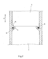
- Such a pipe connection piece 4 is shown in FIGS. 2 and 3 are shown by way of example, in which Fig. 2 shows a first embodiment and Fig. 3 shows a second and preferred embodiment of the invention.
- each round tube 2 respectively headpiece side, that is, a peripheral circumferential, with respect to the inner wall of the respective round tube 2 arranged radially inwardly offset and towards the respective head piece 3, that is the respective pipe connection piece 4 facing extension 5 respectively as shown in FIGS. 1 and 2 can be seen.
- This extension 5 forms in the embodiment of FIG. 2, a radially circumferential groove 14, which provides a volume space between extension 5 on the one hand and the inner wall of the pipe connection piece 4 on the other.
- this provided by the groove 14 volume space in the course of forming a solder joint with solder is at least partially filled.
- a soldering ring is formed, which connects the round tube 2 with the pipe connection piece 4 heating medium tight.
- the pipe connection piece side arranged on the round tube 2 extension 5 ensures that the introduced into the groove 14 Lotgut during the soldering process does not unintentionally drip or flow away, that can escape. With the embodiment according to the invention, therefore, the formation of a proper and heating medium-tight solder joint is ensured.
- Fig. 3 shows a further and preferred embodiment of the invention.
- the round tube 2 has an outer diameter D AR .
- the end region 7 of the round tube 2 has a pipe wall 13 reduced in its outer diameter.
- the pipe connection piece 4 has an outer diameter DAS, which corresponds to the outer diameter D AR of the round tube 2. In this way an externally virtually seamless tube header connection is provided.
- the inner diameter D IS of the pipe connection piece 4 corresponds to the inner diameter D IR of the round tube 2.
- This inner diameter of the pipe connection 4 is in the opposite end of the round tube 2 6 of the pipe connection 4 formed extended, that is, the inner diameter D ISe in the end portion 6 of the pipe connection 4 is opposite the inner diameter D IS of the pipe connection 4 increases.
- the above-described outer and inner diameter configuration of the round tube 2 on the one hand and the pipe connection 4 on the other hand advantageously has the effect that the round tube 2 can be inserted into the pipe connection piece 4, which helps to form a safer connection between the round tube 2 and pipe connection piece 4, as For example, in the embodiment of FIG. 2, after which the round tube 2 and the pipe connection piece 4 are frontally adjacent to each other.
- the end portion 6 of the pipe connection piece 4 with the diameter-expanded inner diameter D ISe in the longitudinal direction 9 of the pipe connection piece 4 extends over a length L SÜ same, the longitudinal extent L RÜ of the end portion 7 of the Round tube 2 with a diameter reduced outside diameter D ARr exceeds.
- this groove 14 provides a volume space, wherein this volume space in the embodiment of FIG. 3 is created by the extension 5 arranged on the round tube 2 having the extension 11 between the expanded and non-expanded inner diameter D lS or D ISe of the pipe connection 4 formed shoulder 12 cooperates.
- the longitudinal extent L SÜ of the pipe connection 4 and the longitudinal extension L RÜ of the round tube 2 in the coverage area of round tube 2 and pipe connection 4 are coordinated such that the round tube 2 over a defined length in the longitudinal direction 9 in the Pipe connection 4 can be inserted, wherein in this defined position of the round tube 2 to the pipe connection piece 4, as shown in Fig. 3, a groove 14 is formed, which creates a defined volume space for receiving Lotgut.
- the peculiarity of the construction according to the invention is to provide an end 5 arranged on the round tube 2, which creates in cooperation with the inner wall of the pipe connection 4 a volumizing providing groove 14, which is ensured as a result of this configuration that in the groove 14 introduced Lotgut can not escape unintentionally, so that a heating medium-tight solder joint between round tube 2 and pipe connection piece 4 is ensured.
Abstract
Description
Die Erfindung betrifft einen Heizkörper, insbesondere einen Mehrsäuler-Heizkörper, mit einer Mehrzahl von von einem Heizmedium durchströmbaren Rundrohren und ein- wie anderendseitig der Rundrohre angeordneten Kopfstücken, mittels derer die Rundrohre strömungstechnisch miteinander verbunden sind.The invention relates to a radiator, in particular a Mehrsäuler radiator, with a plurality of through-flow of a heating medium round tubes and on the other end side of the round tubes arranged head pieces, by means of which the round tubes are fluidically connected to each other.
Die vorbeschriebene Heizkörperkonstruktion, bestehend aus Rundrohren einerseits und die Rundrohre strömungstechnisch miteinander verbindenden Kopfstücken andererseits, welche beispielsweise als Einzelglied zur Herstellung von Mehrsäuler-Heizkörpern Verwendung finden kann, ist aus dem Stand der Technik an sich bekannt, weshalb es eines gesonderten druckschriftlichen Nachweises an dieser Stelle nicht bedarf.The above-described radiator construction, consisting of round tubes on the one hand and the round tubes fluidly interconnecting headers on the other hand, which can be used for example as a single member for the production of Mehrsäuler radiators, is known from the prior art, which is why a separate printed evidence at this point not needed.
Zur strömungstechnischen Verbindung der einzelnen Rundrohre mit den Kopfstücken tragen die Kopfstücke eine der Anzahl der Rundrohre entsprechende Anzahl an Rohranschlußstutzen, in die die Rundrohre im montierten Zustand des Heizkörpers endbereichsseitig eingeführt sind. Auf diese Weise entsteht ein geschlossener Strömungskreislauf für das Heizmedium, welches im Betriebsfall durch die Rundrohre und die die Rundrohre strömungstechnisch miteinander verbindenden Kopfstücke geführt wird.For aerodynamic connection of the individual round tubes with the head pieces carry the head pieces one of the number of round tubes corresponding number of pipe connection piece, in which the round tubes are inserted endbereichsseitig in the assembled state of the radiator. In this way, a closed flow circuit for the heating medium, which is guided in operation by the round tubes and the round tubes fluidly interconnecting headers.
Für einen heizmediumdichten Anschluß der Rundrohre an die Kopfstücke werden die Rundrohre jeweils endseitig mit dem zugehörigen Kopfstück verschweißt oder verlötet, wobei sich insbesondere das Verlöten in der Praxis bewährt hat.For a heating medium-tight connection of the round tubes to the headers, the round tubes are each welded or soldered at the ends with the associated head, in particular, the soldering has proven in practice.
Aus fertigungstechnischen Gründen erfolgt das Verlöten der Rundrohre mit den Kopfstücken in liegender Ausrichtung der Einzelkomponenten. Hierbei entsteht das Problem, daß sich beim Verflüssigen des Lotes Teilmengen des Lotgutes lösen, die infolge der hohen Eigenspannung des Lotgutes wegfließen können. Dies hat in nachteiliger Weise zur Konsequenz, daß an den Fügestellen zwischen Rundrohren einerseits und Kopfstücken andererseits zu wenig Lot vorhanden sein kann, was dazu führt, daß die Rundrohre und die Kopfstücke nicht heizmediumdicht miteinander verbunden sind, so daß es im Betriebsfall des Heizkörpers zu ungewollten Leckagen kommen kann.For manufacturing reasons, the soldering of the round tubes with the headers in a horizontal orientation of the individual components. This creates the problem that solve during liquefaction of the solder subsets of Lotgutes, which can flow away due to the high residual stress of the Lotgutes. This has the disadvantage that at the joints between round tubes on the one hand and headers on the other hand too little solder can be present, which leads to the fact that the round tubes and the headers are not connected to each other so that they are heat-resistant in the operating case of the radiator Leaks can come.
Die Aufgabe der Erfindung ist es, unter Vermeidung der vorgenannten Nachteile einen Heizkörper bereitzustellen, der auf konstruktiv einfache Weise eine heizmediumdichte Verbindung zwischen den Rundrohren einerseits und den Kopfstücken andererseits bereitstellt.The object of the invention is to provide a radiator while avoiding the aforementioned disadvantages, which provides a heating medium-tight connection between the round tubes on the one hand and the headers on the other hand in a structurally simple manner.
Zur Lösung dieser Aufgabe wird mit der Erfindung vorgeschlagen, daß ein jedes Rundrohr jeweils kopfstückseitig einen umlaufenden, mit Bezug auf die Innenwandung des jeweiligen Rundrohres radial nach innen versetzt angeordneten und in Richtung auf das jeweilige Kopfstück weisenden Fortsatz aufweist.To achieve this object, it is proposed with the invention that each round tube has a circumferential head end, with respect to the inner wall of the respective circular tube radially offset inwardly and pointing in the direction of the respective headpiece extension.
Dieser erfindungsgemäß kopfstückseitig am jeweiligen Rundrohr vorgesehene Fortsatz dient als Rückströmbarriere für das beim Verbinden des Rundrohres mit dem Kopfstück an die Fügestelle zwischen Rundrohr und Kopfstück zu bringende Lotgut. Mit der erfindungsgemäßen Konstruktion wird also sichergestellt, daß sich beim Verflüssigen des Lotes nicht Teilmengen des Lotgutes lösen und in unerwünschter Weise wegfließen können. Damit gewährleistet die erfindungsgemäße Ausgestaltung auf einfache Weise die Ausbildung einer heizmediumdichten Verbindung zwischen den Rundrohren einerseits und den Kopfstücken andererseits, weil der kopfstückseitig an den Rundrohren jeweils angeordnete Fortsatz sicherstellt, daß das im Zuge des Lötvorganges verflüssigte Lotgut an der vorgesehenen Fügestelle verbleibt. Der endseitig an den Rundrohren jeweils angeordnete Fortsatz stellt für das Lotgut eine Art Käfig zur Halterung des sich im Bereich der Fügestelle ausbildenden Lötrings dar, so daß dieser nicht in unerwünschter Weise abspringen kann. Die aus fertigungstechnischen Gründen beim Verlöten der Rundrohre mit den Kopfstücken bevorzugte liegende Ausrichtung der miteinander zu verbindenden Komponenten kann auch bei einer Ausgestaltung nach der Erfindung in vorteilhafter Weise beibehalten werden, wobei der endseitig an den Rundrohren jeweils angeordnete Fortsatz in der schon vorbeschriebenen Weise sicherstellt, daß verflüssigtes Lotgut an der gewünschten Fügestelle verbleibt und nicht, wie bei den aus dem Stand der Technik bekannten Anordnungen, in unerwünschter Weise entweicht. Eine heizmediumdichte Verbindung zwischen den Rundrohren und den Kopfstücken ist so gewährleistet.This inventive headpiece side provided on the respective round tube extension serves as Rückströmbarriere for when connecting the round tube with the head piece to the joint between the round tube and head piece to be brought solder. With the construction according to the invention is thus ensured that do not dissolve subsets of the Lotgutes during liquefaction of the solder and can flow away in an undesirable manner. In order to ensure the inventive design in a simple manner the formation of a heating medium-tight connection between the round tubes on the one hand and the head pieces on the other hand, because the headpiece side of each of the round tubes arranged extension ensures that the liquefied in the course of soldering Lotgut remains at the intended joint. The end at the round tubes each arranged extension provides for the Lotgut a kind of cage for holding the forming in the region of the joint solder ring, so that it can not jump off in an undesirable manner. The preferred for manufacturing reasons when soldering the round tubes with the headers lying orientation of the components to be joined together can be maintained in an embodiment of the invention in an advantageous manner, the end of the round tubes respectively arranged extension ensures in the already described manner that liquefied Lotgut remains at the desired joint and not, as in the known from the prior art arrangements, escapes in an undesirable manner. A heating medium-tight connection between the round tubes and the headers is guaranteed.
Um eine äußerlich praktisch übergangslose Rohr-Kopfstückverbindung zu schaffen, werden gemäß einer besonderen und bevorzugten Ausgestaltungsform der Erfindung einerseits die in die Kopfstücke einzuschiebenden Rundrohre am jeweiligen Rohrende bezüglich ihres äußeren Durchmessers abgedreht und andererseits jeweils die zugehörigen Rohranschlußstücke der Kopfstücke hinsichtlich ihres Innendurchmessers ausgedreht. Nach dieser besonderen Ausgestaltung der Erfindung zeichnet sich der Heizkörper dadurch aus, daß der jeweilige Endbereich eines Rundrohres, an den sich der das Lotgut zurückhaltende Fortsatz vorzugsweise einstückig anschließt, eine im Außendurchmesser reduzierte Rohrwandung aufweist und daß der einem Rundrohr zugewandte Endbereich eines jeden Rohranschlußstutzens einen erweiterten Innendurchmesser aufweist. Dabei wirkt der am jeweiligen Rundrohr angeordnete Fortsatz mit dem im Übergangsbereich zwischen erweitertem und nicht erweitertem Innendurchmesser des jeweils zugehörigen Rohranschlußstutzens ausgebildeten Absatz unter Ausbildung einer umlaufenden und rohranschlußstutzenseitig offenen Nut zusammen. Der von dieser Nut bereitgestellte Volumenraum befindet sich im Bereich der Fügestelle zwischen Rundrohr einerseits und Rohranschlußstutzen andererseits und nimmt das während des Verlötvorganges noch flüssige Lötgut auf. Aufgrund der umlaufenden Ausgestaltung des Fortsatzes bzw. der Nut entsteht ein das Rundrohr mit dem Rohranschlußstutzen heizmediumdicht verbindender Lötring, der von der Nut nach Art eines Käfigs zur Halterung desselben gefangen ist, was ein unerwünschtes Entweichen des Lotgutes sicher verhindert.In order to provide an externally virtually seamless tube-head joint, according to a particular and preferred embodiment of the invention, on the one hand to be inserted into the head pieces round tubes at the respective tube end turned off with respect to its outer diameter and on the other hand in each case turned off the corresponding pipe fittings of the head pieces in terms of their inner diameter. According to this particular embodiment of the invention, the radiator is characterized in that the respective end portion of a round tube to which the Lotgut restraining extension preferably integrally connects, having a reduced outer diameter tube wall and that of a round tube facing end portion of each pipe connection an expanded Inner diameter has. In this case, the extension arranged on the respective round tube cooperates with the shoulder formed in the transition region between the extended and non-expanded inner diameter of the respectively associated pipe connection piece to form a circumferential groove open on the side of the pipe connection. The provided by this groove volume space is located in the region of the joint between the round tube on the one hand and pipe connection piece on the other hand and takes on the still soldering during the soldering process. Due to the circumferential configuration of the extension or the groove creates a round tube with the pipe connection piece heating medium tightly connected solder ring, which is caught by the groove in the manner of a cage for holding the same, which reliably prevents unwanted escape of Lotgutes.
Gemäß einem weiteren Merkmal der Erfindung ist bei der nach der Erfindung bevorzugten Ausführungsform vorgesehen, daß sich der jeweilige Endbereich eines Rundrohres mit im Außendurchmesser reduzierter Rohrwandung in Längsrichtung des Rundrohres über eine Länge desselben von 1 cm bis 4 cm, vorzugsweise von 2 cm bis 3 cm erstreckt. Der Endbereich eines Rohranschlußstutzens mit im Durchmesser erweitertem Innendurchmesser erstreckt sich in Längsrichtung des Rohranschlußstutzens indes über eine Länge desselben, die die Längserstreckung des Endbereichs mit im Durchmesser reduziertem Außendurchmesser des zugehörigen Rundrohres übersteigt. Auf diese Weise wird sichergestellt, daß der rohranschlußstutzenseitig am Rundrohr angeordnete Fortsatz mit dem Rundrohr zugewandten Endbereich des Rohranschlußstutzens unter Ausbildung einer einen Volumenraum bereitstellenden Nut - wie vorstehend erläutert - zusammenwirkt.According to a further feature of the invention, it is provided in the embodiment preferred according to the invention that the respective end portion of a round tube with reduced outer diameter tube wall in the longitudinal direction of the round tube over a length thereof from 1 cm to 4 cm, preferably from 2 cm to 3 cm extends. However, the end portion of a pipe fitting having an enlarged diameter inside diameter extends longitudinally of the pipe fitting over a length thereof that exceeds the longitudinal extent of the end portion having the reduced diameter outer diameter of the associated round pipe. In this way it is ensured that the pipe connection piece side arranged on the round tube extension with the round tube facing end portion of the pipe connection piece to form a groove providing a volume space - as explained above - cooperates.
Generell gilt, daß die Dicke der Rohrwandung im Bereich des rohranschlußstutzenseitigen Endbereiches des Rundrohres, der eine im Außendurchmesser reduzierte Rohrwandung aufweist, so zu bemessen ist, daß eine hinreichende Stabilität des Endbereiches des Rundrohres sichergestellt ist. Beispielsweise können die jeweiligen Endbereiche der Rundrohre eine im Außendurchmesser um 1 cm bis 3 cm, vorzugsweise 1,5 cm bis 2,5 cm reduzierte Rohrwandung aufweisen, je nach Dicke der Rohrwandung des Rundrohres im nicht im Durchmesser reduzierten Rohrwandbereich. Nach einer möglichen Ausgestaltungsform der Erfindung kann beispielsweise vorgesehen sein, den Außendurchmesser eines Rundrohres mit 25 cm auszulegen. Im kopfstückseitigen Endbereich des Rundrohres verfügt dieses dann beispielsweise über einen Außendurchmesser von 23,6 cm, das heißt das Rundrohr ist in diesem Bereich im Außendurchmesser um 1,4 cm reduziert.In general, that the thickness of the pipe wall in the region of the pipe connection side end portion of the round tube, which has a reduced outer diameter tube wall, is to be dimensioned so that a sufficient stability of the end portion of the round tube is ensured. For example, the respective end regions of the round tubes may have a tube wall reduced in outside diameter by 1 cm to 3 cm, preferably 1.5 cm to 2.5 cm, depending on the thickness of the tube wall of the round tube in the tube wall region which is not reduced in diameter. According to a possible embodiment of the invention, for example, be provided to interpret the outer diameter of a round tube with 25 cm. In the headpiece-side end of the round tube this then has, for example, an outer diameter of 23.6 cm, that is, the round tube is reduced in this area in the outer diameter by 1.4 cm.
Um die Rundrohre endbereichsseitig in die dafür vorgesehenen Rohranschlußstutzen der Kopfstücke sicher einführen zu können, ist gemäß einem weiteren Merkmal der Erfindung vorgesehen, daß der im Durchmesser reduzierte Außendurchmesser eines jeden Rundrohres im wesentlichen dem im Durchmesser erweiterten Innendurchmesser des zugehörigen Rohranschlußstutzens entspricht. Um darüber hinaus eine äußerlich übergangslose Rohr-Kopfstückverbindung zu schaffen, ist gemäß einem weiteren Merkmal der Erfindung vorgesehen, daß die Rohranschlußstutzen einen dem im Durchmesser nicht reduzierten Außendurchmesser der Rundrohre entsprechenden Außendurchmesser aufweisen.In order to introduce the round tubes endbereichsseitig in the space provided pipe connection piece of the head pieces is provided according to a further feature of the invention that the reduced diameter outer diameter of each round tube substantially corresponds to the diameter-expanded inner diameter of the associated pipe connection piece. In addition, to provide an externally seamless tube header connection, it is provided according to a further feature of the invention that the Pipe connection piece have a diameter not reduced outside diameter of the round tubes corresponding outer diameter.
Weitere Merkmale und Vorteile der Erfindung ergeben sich aus der nachfolgenden Beschreibung anhand der Fign. Dabei zeigen:
- Fig. 1
- in einer schematischen Darstellung einen erfindungsgemäßen Heizkörper;
- Fig. 2
- schematisch in einer geschnittenen Seitenansicht die Verbindungsstelle zwischen einem Rundrohr und einem Rohranschlußstutzen gemäß einer ersten Ausführungsform und
- Fig. 3
- schematisch in einer geschnittenen Seitenansicht die Verbindungsstelle zwischen einem Rundrohr und einem Rohranschlußstutzen gemäß einer zweiten Ausführungsform.
- Fig. 1
- in a schematic representation of a radiator according to the invention;
- Fig. 2
- schematically in a sectional side view of the joint between a round tube and a pipe connection piece according to a first embodiment and
- Fig. 3
- schematically in a sectional side view of the joint between a round tube and a pipe connection piece according to a second embodiment.
Fig. 1 zeigt einen erfindungsgemäßen Heizkörper 1 in rein schematischer Darstellung. Rohranschlüsse für den Heizkörper 1, Regelventile, Zu- und Abführungsleitungen für das Heizmedium und dergleichen sind der besseren Übersicht wegen in Fig. 1 nicht dargestellt.Fig. 1 shows a
Aus Fig. 1 ist zu erkennen, daß der erfindungsgemäße Heizkörper 1 aus Rundrohren 2 einerseits und Kopfstücken 3 andererseits gebildet ist. Ein- wie anderendseitig sind die Rundrohre 2 jeweils mittels eines Kopfstückes 3 strömungstechnisch miteinander verbunden. Wie aus Fig. 1 zu erkennen ist, erstrecken sich die Rundrohre 2 zwischen den beiden Kopfstücken 3 in Längsrichtung 9, wobei die Rundrohre 2 in einer quer zur Längsrichtung 9 liegenden Richtung nebeneinander angeordnet sind.From Fig. 1 it can be seen that the
Die Rundrohre 2 werden bei einem Betrieb des Heizkörpers 1 von einem Heizmedium, welches beispielsweise Wasser sein kann, durchströmt. Über die Kopfstücke 3 sind die Rundrohre 2 strömungstechnisch miteinander verkoppelt, so daß ein geschlossener Strömungskreislauf für das den Heizkörper 1 durchströmende Heizmedium entsteht. Um ungewollte Leckagen zu vermeiden, sind die Rundrohre 2 und die Kopfstücke 3 heizmediumdicht miteinander verbunden. Die nach der Erfindung im besonderen ausgestaltete heizmediumdichte Verbindung zwischen den Rundrohren 2 und den Kopfstücken 3 ist in den Fign. 2 und 3 dargestellt.The
Ein jedes Kopfstück 3 des Heizkörpers 1 verfügt über der Anzahl der Rundrohre 2 entsprechend viele Rohranschlußstutzen 4, wobei ein jeder Rohranschlußstutzen 4 eines Kopfstückes 3 dem Anschlußbereich eines Rundrohres 2 zugeordnet ist. Ein solcher Rohranschlußstutzen 4 ist in den Fign. 2 und 3 beispielhaft gezeigt, wobei Fig. 2 eine erste Ausführungsform und Fig. 3 eine zweite und bevorzugte Ausführungsform der Erfindung zeigt.Each
Erfindungsgemäß ist vorgesehen, daß ein jedes Rundrohr 2 jeweils kopfstückseitig, das heißt rohranschlußstutzenseitig einen umlaufenden, mit Bezug auf die Innenwandung des jeweiligen Rundrohres 2 radial nach innen versetzt angeordneten und in Richtung auf das jeweilige Kopfstück 3, das heißt den jeweiligen Rohranschlußstutzen 4 weisenden Fortsatz 5 aufweist, wie in den Fign. 1 und 2 zu erkennen ist. Dieser Fortsatz 5 bildet in dem Ausführungsbeispiel nach Fig. 2 eine radial umlaufende Nut 14 aus, die einen Volumenraum zwischen Fortsatz 5 einerseits und Innenwandung des Rohranschlußstutzens 4 andererseits bereitstellt. Für ein heizmediumdichtes Verbinden von Rohranschlußstutzen 4 und Rundrohr 2 wird dieser von der Nut 14 bereitgestellte Volumenraum im Zuge der Ausbildung einer Lötverbindung mit Lötgut zumindest teilweise befüllt. Aufgrund der radial umlaufenden Nut 14 bildet sich ein Lötgutring aus, der das Rundrohr 2 mit dem Rohranschlußstutzen 4 heizmediumdicht verbindet. Dabei sorgt der rohranschlußstutzenseitig am Rundrohr 2 angeordnete Fortsatz 5 dafür, daß das in die Nut 14 eingebrachte Lotgut während des Lötvorganges nicht ungewollt abtropfen oder wegströmen, das heißt entweichen kann. Mit der erfindungsgemäßen Ausgestaltung wird also die Ausbildung einer ordnungsgemäßen und heizmediumdichten Lötverbindung sichergestellt.According to the invention it is provided that each
Fig. 3 zeigt ein weiteres und bevorzugtes Ausführungsbeispiel der Erfindung. Nach dieser Ausgestaltung besitzt das Rundrohr 2 einen Außendurchmesser DAR. Der Endbereich 7 des Rundrohres 2, der dem Rohranschlußstutzen 4 gegenüber liegt, verfügt indes über einen Außendurchmesser DARr, der gegenüber dem Außendurchmesser DAR des Rundrohres 2 reduziert ist. Mit anderen Worten: Der Endbereich 7 des Rundrohres 2 weist eine im Außendurchmesser reduzierte Rohrwandung 13 auf.Fig. 3 shows a further and preferred embodiment of the invention. According to this embodiment, the
An die im Durchmesser reduzierte Rohrwandung 13 des Rundrohres 2 schließt sich der am Rundrohr 2 angeordnete Fortsatz 5 an, und zwar vorzugsweise einstückig, wie in Fig. 3 dargestellt.At the reduced in
Der Rohranschlußstutzen 4 verfügt über einen Außendurchmesser DAS, der dem Außendurchmesser DAR des Rundrohres 2 entspricht. Auf diese Weise wird eine äußerlich praktisch übergangslose Rohr-Kopfstückverbindung geschaffen.The
Der Innendurchmesser DIS des Rohranschlußstutzens 4 entspricht dem Innendurchmesser DIR des Rundrohres 2. Dieser Innendurchmesser des Rohranschlußstutzens 4 ist in dem dem Rundrohr 2 gegenüberliegenden Endbereich 6 des Rohranschlußstutzens 4 erweitert ausgebildet, das heißt der Innendurchmesser DISe im Endbereich 6 des Rohranschlußstutzens 4 ist gegenüber dem Innendurchmesser DIS des Rohranschlußstutzens 4 vergrößert.The inner diameter D IS of the
Die vorbeschriebene Außen- und Innendurchmesserausgestaltung des Rundrohres 2 einerseits und des Rohranschlußstutzens 4 andererseits hat in vorteilhafter Weise die Wirkung, daß das Rundrohr 2 in den Rohranschlußstutzen 4 eingeführt werden kann, was dazu beiträgt, eine sicherere Verbindung zwischen Rundrohr 2 und Rohranschlußstutzen 4 auszubilden, als beispielsweise in der Ausgestaltungsform nach Fig. 2, wonach das Rundrohr 2 und der Rohranschlußstutzen 4 stirnseitig aneinander liegen.The above-described outer and inner diameter configuration of the
Bevorzugterweise ist vorgesehen, daß sich - wie in Fig. 3 gezeigt - der Endbereich 6 des Rohranschlußstutzens 4 mit im Durchmesser erweitertem Innendurchmesser DISe in Längsrichtung 9 des Rohranschlußstutzens 4 über eine Länge LSÜ desselben erstreckt, die die Längserstreckung LRÜ des Endbereichs 7 des Rundrohres 2 mit im Durchmesser reduziertem Außendurchmesser DARr übersteigt. Durch diese konstruktive Ausgestaltung bildet sich im montierten Zustand von Rundrohr 2 und Rohranschlußstutzen 4 eine Nut 14 zwischen am Rundrohr 2 endseitig angeordnetem Fortsatz 5 und Innenwandung des Rohranschlußstutzens 4 aus. In der schon anhand von Fig. 2 vorbeschriebenen Weise stellt diese Nut 14 einen Volumenraum bereit, wobei dieser Volumenraum bei der Ausführungsform nach Fig. 3 dadurch entsteht, daß der am Rundrohr 2 angeordnete Fortsatz 5 mit dem im Übergangsbereich 11 zwischen erweitertem und nicht erweitertem Innendurchmesser DlS bzw. DISe des Rohranschlußstutzens 4 ausgebildeten Absatz 12 zusammenwirkt.Preferably, it is provided that - as shown in Fig. 3 - the
Wie Fig. 3 des weiteren erkennen läßt, sind die Längserstreckung LSÜ des Rohranschlußstutzens 4 und die Längserstreckung LRÜ des Rundrohres 2 im Überdeckungsbereich von Rundrohr 2 und Rohranschlußstutzen 4 derart aufeinander abgestimmt, daß das Rundrohr 2 über eine definierte Länge in Längsrichtung 9 in den Rohranschlußstutzen 4 eingeschoben werden kann, wobei in dieser definierten Lage des Rundrohres 2 zum Rohranschlußstutzen 4, wie sie in Fig. 3 gezeigt ist, eine Nut 14 entsteht, die einen definiert großen Volumenraum zur Aufnahme von Lotgut schafft.As can be seen Fig. 3 of the further, the longitudinal extent L SÜ of the
Wie aus den vorstehend erläuterten Fign. hervorgeht, besteht die Besonderheit der erfindungsgemäßen Konstruktion darin, einen endseitig am Rundrohr 2 angeordneten Fortsatz 5 bereitzustellen, der in Zusammenwirkung mit der Innenwandung des Rohranschlußstutzens 4 eine einen Volumenraum bereitstellende Nut 14 schafft, wobei infolge dieser Ausgestaltung sichergestellt ist, daß in die Nut 14 eingebrachtes Lotgut nicht ungewollt entweichen kann, so daß eine heizmediumdichte Lötverbindung zwischen Rundrohr 2 und Rohranschlußstutzen 4 sichergestellt ist.As is apparent from the above-explained Figs. It is apparent that the peculiarity of the construction according to the invention is to provide an
- 11
- Heizkörperradiator
- 22
- Rundrohrround tube
- 33
- Kopfstückheadpiece
- 44
- RohranschlußstutzenPipe connection
- 55
- Fortsatzextension
- 66
- Endbereich RohranschlußstutzenEnd area of pipe connection piece
- 77
- Endbereich RundrohrEnd area round tube
- 88th
- Lotringsolder ring
- 99
- Längsrichtunglongitudinal direction
- 1010
- Verbindungsbereichconnecting area
- 1111
- ÜbergangsbereichTransition area
- 1212
- Absatzparagraph
- 1313
- Rohrwandungpipe wall
- 1414
- Nutgroove
- DAR D AR
- Außendurchmesser RundrohrOuter diameter round tube
- DlR D lR
- Innendurchmesser RundrohrInner diameter round tube
- DASTHE
- Außendurchmesser RohranschlußstutzenOuter diameter pipe connection piece
- DIS D IS
- Innendurchmesser RohranschlußstutzenInner diameter pipe connection piece
- DARr DARr
- Außendurchmesser Rundrohr, reduziertOuter diameter round tube, reduced
- DlSe D lSe
- Innendurchmesser Rohranschlußstutzen, erweitertInner diameter pipe connection, extended
- LSÜ L SÜ
- Längserstreckung des Rohranschlußstutzens im ÜberdeckungsbereichLongitudinal extension of the pipe connection in the covering area
- LRÜ L RÜ
- Längserstreckung des Rundrohres im ÜberdeckungsbereichLongitudinal extent of the round tube in the covering area
Claims (10)
dadurch gekennzeichnet,
daß ein jedes Rundrohr (2) jeweils kopfstückseitig einen umlaufenden, mit Bezug auf die Innenwandung des jeweiligen Rundrohres (2) radial nach innen versetzt angeordneten und in Richtung auf das jeweilige Kopfstück (3) weisenden Fortsatz (5) aufweist.Radiator, in particular Mehrsäuler radiator, with a plurality of through-flow of a heating medium round tubes (2) and on the other end of the round tubes (2) arranged head pieces (3), by means of which the round tubes (2) are fluidically connected to each other,
characterized,
that each round tube (2) each headpiece side has a circumferential, with respect to the inner wall of the respective round tube (2) radially inwardly arranged and pointing in the direction of the respective head piece (3) extension (5).
Priority Applications (4)
| Application Number | Priority Date | Filing Date | Title |
|---|---|---|---|
| EP05023205A EP1780491B1 (en) | 2005-10-25 | 2005-10-25 | Radiator, in particular multi-column radiator |
| PL05023205T PL1780491T3 (en) | 2005-10-25 | 2005-10-25 | Radiator, in particular multi-column radiator |
| AT05023205T ATE401544T1 (en) | 2005-10-25 | 2005-10-25 | RADIATORS, ESPECIALLY MULTI-COLUMN RADIATORS |
| DE502005004744T DE502005004744D1 (en) | 2005-10-25 | 2005-10-25 | Radiator, in particular Mehrsäuler radiator |
Applications Claiming Priority (1)
| Application Number | Priority Date | Filing Date | Title |
|---|---|---|---|
| EP05023205A EP1780491B1 (en) | 2005-10-25 | 2005-10-25 | Radiator, in particular multi-column radiator |
Publications (2)
| Publication Number | Publication Date |
|---|---|
| EP1780491A1 true EP1780491A1 (en) | 2007-05-02 |
| EP1780491B1 EP1780491B1 (en) | 2008-07-16 |
Family
ID=35788986
Family Applications (1)
| Application Number | Title | Priority Date | Filing Date |
|---|---|---|---|
| EP05023205A Active EP1780491B1 (en) | 2005-10-25 | 2005-10-25 | Radiator, in particular multi-column radiator |
Country Status (4)
| Country | Link |
|---|---|
| EP (1) | EP1780491B1 (en) |
| AT (1) | ATE401544T1 (en) |
| DE (1) | DE502005004744D1 (en) |
| PL (1) | PL1780491T3 (en) |
Citations (10)
| Publication number | Priority date | Publication date | Assignee | Title |
|---|---|---|---|---|
| BE413610A (en) * | 1900-01-01 | |||
| FR1425677A (en) * | 1965-02-16 | 1966-01-24 | Buderus Eisenwerk | Tubular radiator |
| US3830262A (en) * | 1972-04-20 | 1974-08-20 | Aeroquip Corp | Article for soldering aluminum to copper |
| DE4404928A1 (en) * | 1993-03-12 | 1994-09-15 | Silvano Becchi | Heater of metal tubes intimately connected to one another, and method of producing it |
| EP0622601A1 (en) * | 1993-04-26 | 1994-11-02 | Sanden Corporation | Heat exchanger |
| DE19823635A1 (en) * | 1998-05-27 | 1999-12-02 | Thermo Technik Holding Ag Reut | Fabrication of radiator for bathrooms |
| EP1179723A2 (en) * | 2000-08-09 | 2002-02-13 | Deltacalor S.r.L. | Heating device |
| US6446857B1 (en) * | 2001-05-31 | 2002-09-10 | Delphi Technologies, Inc. | Method for brazing fittings to pipes |
| WO2004090449A1 (en) * | 2003-04-08 | 2004-10-21 | Laminox S.R.L. | Production process for bathroom hot water radiators |
| WO2005014199A1 (en) * | 2003-08-12 | 2005-02-17 | Alberto Sacristani | Method and machinery for manufacturing a radiator element, radiator element and radiator |
-
2005
- 2005-10-25 PL PL05023205T patent/PL1780491T3/en unknown
- 2005-10-25 DE DE502005004744T patent/DE502005004744D1/en active Active
- 2005-10-25 EP EP05023205A patent/EP1780491B1/en active Active
- 2005-10-25 AT AT05023205T patent/ATE401544T1/en active
Patent Citations (10)
| Publication number | Priority date | Publication date | Assignee | Title |
|---|---|---|---|---|
| BE413610A (en) * | 1900-01-01 | |||
| FR1425677A (en) * | 1965-02-16 | 1966-01-24 | Buderus Eisenwerk | Tubular radiator |
| US3830262A (en) * | 1972-04-20 | 1974-08-20 | Aeroquip Corp | Article for soldering aluminum to copper |
| DE4404928A1 (en) * | 1993-03-12 | 1994-09-15 | Silvano Becchi | Heater of metal tubes intimately connected to one another, and method of producing it |
| EP0622601A1 (en) * | 1993-04-26 | 1994-11-02 | Sanden Corporation | Heat exchanger |
| DE19823635A1 (en) * | 1998-05-27 | 1999-12-02 | Thermo Technik Holding Ag Reut | Fabrication of radiator for bathrooms |
| EP1179723A2 (en) * | 2000-08-09 | 2002-02-13 | Deltacalor S.r.L. | Heating device |
| US6446857B1 (en) * | 2001-05-31 | 2002-09-10 | Delphi Technologies, Inc. | Method for brazing fittings to pipes |
| WO2004090449A1 (en) * | 2003-04-08 | 2004-10-21 | Laminox S.R.L. | Production process for bathroom hot water radiators |
| WO2005014199A1 (en) * | 2003-08-12 | 2005-02-17 | Alberto Sacristani | Method and machinery for manufacturing a radiator element, radiator element and radiator |
Also Published As
| Publication number | Publication date |
|---|---|
| DE502005004744D1 (en) | 2008-08-28 |
| PL1780491T3 (en) | 2008-11-28 |
| EP1780491B1 (en) | 2008-07-16 |
| ATE401544T1 (en) | 2008-08-15 |
Similar Documents
| Publication | Publication Date | Title |
|---|---|---|
| WO2004025196A1 (en) | Cooling agent condenser, mainly for a vehicle air-conditioning device | |
| DE102007020627B3 (en) | Connection element for a radiator | |
| DE3133756A1 (en) | Double-pipe (tube-in-tube) cooler | |
| DE3132602A1 (en) | RADIATOR | |
| DE10348141B3 (en) | Inner heat exchanger for high pressure cooling medium providing dual function as accumulator and cooling medium collector | |
| EP2927632A1 (en) | Heat exchanger | |
| EP1780491B1 (en) | Radiator, in particular multi-column radiator | |
| EP1488185B1 (en) | Heat exchanger | |
| DE102004003325A1 (en) | Coaxial heat exchanger, in particular, for a vehicle heating/ventilating and/or air-conditioning plant comprises at least one structure whose wall thickness with respect to at least one of its other structures is reduced | |
| DE102013202790A1 (en) | Heat exchanger | |
| DE202014002477U1 (en) | heat exchangers | |
| DE1205564B (en) | Tube-tube sheet connection for both tube ends in a tube bundle heat exchanger with a shell space, two tube sheets and the distribution chambers behind | |
| DE102007016940B4 (en) | manifold | |
| DE3521378A1 (en) | Heat exchangers in the form of finned tubes | |
| DE102015010289A1 (en) | Plate heat exchanger | |
| DE102016105902B4 (en) | Process for the production of a tube made of metal with different wall thicknesses | |
| EP3870814A1 (en) | Internally cooled valve having a coolant conducting system | |
| DE102014225159A1 (en) | Heat exchanger | |
| DE10106510B4 (en) | Aluminum heat exchangers | |
| EP3367035A1 (en) | Heat exchanger tube helix and storage container with a heat exchanger tube helix | |
| DE102017210086A1 (en) | connection device | |
| AT506991B1 (en) | CONNECTOR | |
| DE2702542A1 (en) | HEAT RESET, HOLLOW METALLIC COUPLING | |
| DE102009011151A1 (en) | Ribbed radiator separative element for ribbed radiator, has annular sealing element and insert arbor, where sealing element has internal space and insert arbor is inserted in internal space | |
| DE102008052550A1 (en) | Connection device for an internal heat exchanger |
Legal Events
| Date | Code | Title | Description |
|---|---|---|---|
| PUAI | Public reference made under article 153(3) epc to a published international application that has entered the european phase |
Free format text: ORIGINAL CODE: 0009012 |
|
| 17P | Request for examination filed |
Effective date: 20060608 |
|
| AK | Designated contracting states |
Kind code of ref document: A1 Designated state(s): AT BE BG CH CY CZ DE DK EE ES FI FR GB GR HU IE IS IT LI LT LU LV MC NL PL PT RO SE SI SK TR |
|
| AX | Request for extension of the european patent |
Extension state: AL BA HR MK YU |
|
| GRAP | Despatch of communication of intention to grant a patent |
Free format text: ORIGINAL CODE: EPIDOSNIGR1 |
|
| AKX | Designation fees paid |
Designated state(s): AT CH CZ DE IT LI |
|
| GRAS | Grant fee paid |
Free format text: ORIGINAL CODE: EPIDOSNIGR3 |
|
| RBV | Designated contracting states (corrected) |
Designated state(s): AT BE BG CH CY CZ DE DK EE ES FI FR GB GR HU IE IS IT LI LT LU LV MC NL PL PT RO SE SI SK TR |
|
| GRAA | (expected) grant |
Free format text: ORIGINAL CODE: 0009210 |
|
| AK | Designated contracting states |
Kind code of ref document: B1 Designated state(s): AT BE BG CH CY CZ DE DK EE ES FI FR GB GR HU IE IS IT LI LT LU LV MC NL PL PT RO SE SI SK TR |
|
| REG | Reference to a national code |
Ref country code: GB Ref legal event code: FG4D Free format text: NOT ENGLISH |
|
| REG | Reference to a national code |
Ref country code: CH Ref legal event code: EP |
|
| REG | Reference to a national code |
Ref country code: CH Ref legal event code: NV Representative=s name: E. BLUM & CO. AG PATENT- UND MARKENANWAELTE VSP |
|
| REF | Corresponds to: |
Ref document number: 502005004744 Country of ref document: DE Date of ref document: 20080828 Kind code of ref document: P |
|
| REG | Reference to a national code |
Ref country code: IE Ref legal event code: FG4D Free format text: LANGUAGE OF EP DOCUMENT: GERMAN |
|
| REG | Reference to a national code |
Ref country code: PL Ref legal event code: T3 |
|
| NLV1 | Nl: lapsed or annulled due to failure to fulfill the requirements of art. 29p and 29m of the patents act | ||
| PG25 | Lapsed in a contracting state [announced via postgrant information from national office to epo] |
Ref country code: NL Free format text: LAPSE BECAUSE OF FAILURE TO SUBMIT A TRANSLATION OF THE DESCRIPTION OR TO PAY THE FEE WITHIN THE PRESCRIBED TIME-LIMIT Effective date: 20080716 Ref country code: ES Free format text: LAPSE BECAUSE OF FAILURE TO SUBMIT A TRANSLATION OF THE DESCRIPTION OR TO PAY THE FEE WITHIN THE PRESCRIBED TIME-LIMIT Effective date: 20081027 Ref country code: LT Free format text: LAPSE BECAUSE OF FAILURE TO SUBMIT A TRANSLATION OF THE DESCRIPTION OR TO PAY THE FEE WITHIN THE PRESCRIBED TIME-LIMIT Effective date: 20080716 Ref country code: IS Free format text: LAPSE BECAUSE OF FAILURE TO SUBMIT A TRANSLATION OF THE DESCRIPTION OR TO PAY THE FEE WITHIN THE PRESCRIBED TIME-LIMIT Effective date: 20081116 Ref country code: PT Free format text: LAPSE BECAUSE OF FAILURE TO SUBMIT A TRANSLATION OF THE DESCRIPTION OR TO PAY THE FEE WITHIN THE PRESCRIBED TIME-LIMIT Effective date: 20081216 |
|
| PG25 | Lapsed in a contracting state [announced via postgrant information from national office to epo] |
Ref country code: LV Free format text: LAPSE BECAUSE OF FAILURE TO SUBMIT A TRANSLATION OF THE DESCRIPTION OR TO PAY THE FEE WITHIN THE PRESCRIBED TIME-LIMIT Effective date: 20080716 Ref country code: FI Free format text: LAPSE BECAUSE OF FAILURE TO SUBMIT A TRANSLATION OF THE DESCRIPTION OR TO PAY THE FEE WITHIN THE PRESCRIBED TIME-LIMIT Effective date: 20080716 Ref country code: SI Free format text: LAPSE BECAUSE OF FAILURE TO SUBMIT A TRANSLATION OF THE DESCRIPTION OR TO PAY THE FEE WITHIN THE PRESCRIBED TIME-LIMIT Effective date: 20080716 Ref country code: BG Free format text: LAPSE BECAUSE OF FAILURE TO SUBMIT A TRANSLATION OF THE DESCRIPTION OR TO PAY THE FEE WITHIN THE PRESCRIBED TIME-LIMIT Effective date: 20081016 |
|
| REG | Reference to a national code |
Ref country code: IE Ref legal event code: FD4D |
|
| BERE | Be: lapsed |
Owner name: ZEHNDER VERKAUFS- UND VERWALTUNGS A.G. Effective date: 20081031 |
|
| PG25 | Lapsed in a contracting state [announced via postgrant information from national office to epo] |
Ref country code: EE Free format text: LAPSE BECAUSE OF FAILURE TO SUBMIT A TRANSLATION OF THE DESCRIPTION OR TO PAY THE FEE WITHIN THE PRESCRIBED TIME-LIMIT Effective date: 20080716 Ref country code: IE Free format text: LAPSE BECAUSE OF FAILURE TO SUBMIT A TRANSLATION OF THE DESCRIPTION OR TO PAY THE FEE WITHIN THE PRESCRIBED TIME-LIMIT Effective date: 20080716 Ref country code: DK Free format text: LAPSE BECAUSE OF FAILURE TO SUBMIT A TRANSLATION OF THE DESCRIPTION OR TO PAY THE FEE WITHIN THE PRESCRIBED TIME-LIMIT Effective date: 20080716 |
|
| PLBE | No opposition filed within time limit |
Free format text: ORIGINAL CODE: 0009261 |
|
| STAA | Information on the status of an ep patent application or granted ep patent |
Free format text: STATUS: NO OPPOSITION FILED WITHIN TIME LIMIT |
|
| PG25 | Lapsed in a contracting state [announced via postgrant information from national office to epo] |
Ref country code: RO Free format text: LAPSE BECAUSE OF FAILURE TO SUBMIT A TRANSLATION OF THE DESCRIPTION OR TO PAY THE FEE WITHIN THE PRESCRIBED TIME-LIMIT Effective date: 20080716 Ref country code: SK Free format text: LAPSE BECAUSE OF FAILURE TO SUBMIT A TRANSLATION OF THE DESCRIPTION OR TO PAY THE FEE WITHIN THE PRESCRIBED TIME-LIMIT Effective date: 20080716 Ref country code: MC Free format text: LAPSE BECAUSE OF NON-PAYMENT OF DUE FEES Effective date: 20081031 |
|
| 26N | No opposition filed |
Effective date: 20090417 |
|
| REG | Reference to a national code |
Ref country code: FR Ref legal event code: ST Effective date: 20090630 |
|
| PG25 | Lapsed in a contracting state [announced via postgrant information from national office to epo] |
Ref country code: BE Free format text: LAPSE BECAUSE OF NON-PAYMENT OF DUE FEES Effective date: 20081031 |
|
| PG25 | Lapsed in a contracting state [announced via postgrant information from national office to epo] |
Ref country code: FR Free format text: LAPSE BECAUSE OF NON-PAYMENT OF DUE FEES Effective date: 20081031 |
|
| PG25 | Lapsed in a contracting state [announced via postgrant information from national office to epo] |
Ref country code: SE Free format text: LAPSE BECAUSE OF FAILURE TO SUBMIT A TRANSLATION OF THE DESCRIPTION OR TO PAY THE FEE WITHIN THE PRESCRIBED TIME-LIMIT Effective date: 20081016 |
|
| PG25 | Lapsed in a contracting state [announced via postgrant information from national office to epo] |
Ref country code: CY Free format text: LAPSE BECAUSE OF FAILURE TO SUBMIT A TRANSLATION OF THE DESCRIPTION OR TO PAY THE FEE WITHIN THE PRESCRIBED TIME-LIMIT Effective date: 20080716 Ref country code: LU Free format text: LAPSE BECAUSE OF NON-PAYMENT OF DUE FEES Effective date: 20081025 Ref country code: HU Free format text: LAPSE BECAUSE OF FAILURE TO SUBMIT A TRANSLATION OF THE DESCRIPTION OR TO PAY THE FEE WITHIN THE PRESCRIBED TIME-LIMIT Effective date: 20090117 |
|
| PG25 | Lapsed in a contracting state [announced via postgrant information from national office to epo] |
Ref country code: TR Free format text: LAPSE BECAUSE OF FAILURE TO SUBMIT A TRANSLATION OF THE DESCRIPTION OR TO PAY THE FEE WITHIN THE PRESCRIBED TIME-LIMIT Effective date: 20080716 |
|
| PG25 | Lapsed in a contracting state [announced via postgrant information from national office to epo] |
Ref country code: GR Free format text: LAPSE BECAUSE OF FAILURE TO SUBMIT A TRANSLATION OF THE DESCRIPTION OR TO PAY THE FEE WITHIN THE PRESCRIBED TIME-LIMIT Effective date: 20081017 |
|
| PGFP | Annual fee paid to national office [announced via postgrant information from national office to epo] |
Ref country code: IT Payment date: 20101022 Year of fee payment: 6 |
|
| PG25 | Lapsed in a contracting state [announced via postgrant information from national office to epo] |
Ref country code: IT Free format text: LAPSE BECAUSE OF NON-PAYMENT OF DUE FEES Effective date: 20121025 |
|
| REG | Reference to a national code |
Ref country code: CH Ref legal event code: PFUS Owner name: ZEHNDER GROUP INTERNATIONAL AG, CH Free format text: FORMER OWNER: ZEHNDER VERKAUFS- UND VERWALTUNGS AG, CH |
|
| REG | Reference to a national code |
Ref country code: GB Ref legal event code: 732E Free format text: REGISTERED BETWEEN 20170817 AND 20170823 |
|
| REG | Reference to a national code |
Ref country code: DE Ref legal event code: R082 Ref document number: 502005004744 Country of ref document: DE Representative=s name: BRINKMANN & PARTNER PATENTANWAELTE PARTNERSCHA, DE Ref country code: DE Ref legal event code: R082 Ref document number: 502005004744 Country of ref document: DE Representative=s name: STENGER WATZKE RING INTELLECTUAL PROPERTY, DE Ref country code: DE Ref legal event code: R081 Ref document number: 502005004744 Country of ref document: DE Owner name: ZEHNDER GROUP INTERNATIONAL AG, CH Free format text: FORMER OWNER: ZEHNDER VERKAUFS- UND VERWALTUNGS-AG, GRAENICHEN, CH Ref country code: DE Ref legal event code: R082 Ref document number: 502005004744 Country of ref document: DE Representative=s name: RAUSCH WANISCHECK-BERGMANN BRINKMANN PARTNERSC, DE |
|
| REG | Reference to a national code |
Ref country code: AT Ref legal event code: PC Ref document number: 401544 Country of ref document: AT Kind code of ref document: T Owner name: ZEHNDER GROUP INTERNATIONAL AG, CH Effective date: 20171213 |
|
| REG | Reference to a national code |
Ref country code: DE Ref legal event code: R082 Ref document number: 502005004744 Country of ref document: DE Representative=s name: BRINKMANN & PARTNER PATENTANWAELTE PARTNERSCHA, DE Ref country code: DE Ref legal event code: R082 Ref document number: 502005004744 Country of ref document: DE Representative=s name: RAUSCH WANISCHECK-BERGMANN BRINKMANN PARTNERSC, DE |
|
| PGFP | Annual fee paid to national office [announced via postgrant information from national office to epo] |
Ref country code: AT Payment date: 20221020 Year of fee payment: 18 |
|
| PGFP | Annual fee paid to national office [announced via postgrant information from national office to epo] |
Ref country code: PL Payment date: 20221013 Year of fee payment: 18 |
|
| P01 | Opt-out of the competence of the unified patent court (upc) registered |
Effective date: 20230418 |
|
| PGFP | Annual fee paid to national office [announced via postgrant information from national office to epo] |
Ref country code: GB Payment date: 20231020 Year of fee payment: 19 |
|
| PGFP | Annual fee paid to national office [announced via postgrant information from national office to epo] |
Ref country code: DE Payment date: 20231020 Year of fee payment: 19 Ref country code: CZ Payment date: 20231016 Year of fee payment: 19 Ref country code: CH Payment date: 20231102 Year of fee payment: 19 |
|
| PGFP | Annual fee paid to national office [announced via postgrant information from national office to epo] |
Ref country code: PL Payment date: 20231012 Year of fee payment: 19 |