EP1783169A2 - Thermally conductive phase change materials - Google Patents
Thermally conductive phase change materials Download PDFInfo
- Publication number
- EP1783169A2 EP1783169A2 EP06076876A EP06076876A EP1783169A2 EP 1783169 A2 EP1783169 A2 EP 1783169A2 EP 06076876 A EP06076876 A EP 06076876A EP 06076876 A EP06076876 A EP 06076876A EP 1783169 A2 EP1783169 A2 EP 1783169A2
- Authority
- EP
- European Patent Office
- Prior art keywords
- silicone
- block copolymer
- composition
- pcc
- component
- Prior art date
- Legal status (The legal status is an assumption and is not a legal conclusion. Google has not performed a legal analysis and makes no representation as to the accuracy of the status listed.)
- Withdrawn
Links
Images

Classifications
-
- C—CHEMISTRY; METALLURGY
- C08—ORGANIC MACROMOLECULAR COMPOUNDS; THEIR PREPARATION OR CHEMICAL WORKING-UP; COMPOSITIONS BASED THEREON
- C08L—COMPOSITIONS OF MACROMOLECULAR COMPOUNDS
- C08L53/00—Compositions of block copolymers containing at least one sequence of a polymer obtained by reactions only involving carbon-to-carbon unsaturated bonds; Compositions of derivatives of such polymers
-
- C—CHEMISTRY; METALLURGY
- C08—ORGANIC MACROMOLECULAR COMPOUNDS; THEIR PREPARATION OR CHEMICAL WORKING-UP; COMPOSITIONS BASED THEREON
- C08F—MACROMOLECULAR COMPOUNDS OBTAINED BY REACTIONS ONLY INVOLVING CARBON-TO-CARBON UNSATURATED BONDS
- C08F299/00—Macromolecular compounds obtained by interreacting polymers involving only carbon-to-carbon unsaturated bond reactions, in the absence of non-macromolecular monomers
- C08F299/02—Macromolecular compounds obtained by interreacting polymers involving only carbon-to-carbon unsaturated bond reactions, in the absence of non-macromolecular monomers from unsaturated polycondensates
- C08F299/08—Macromolecular compounds obtained by interreacting polymers involving only carbon-to-carbon unsaturated bond reactions, in the absence of non-macromolecular monomers from unsaturated polycondensates from polysiloxanes
-
- C—CHEMISTRY; METALLURGY
- C08—ORGANIC MACROMOLECULAR COMPOUNDS; THEIR PREPARATION OR CHEMICAL WORKING-UP; COMPOSITIONS BASED THEREON
- C08K—Use of inorganic or non-macromolecular organic substances as compounding ingredients
- C08K3/00—Use of inorganic substances as compounding ingredients
-
- C—CHEMISTRY; METALLURGY
- C08—ORGANIC MACROMOLECULAR COMPOUNDS; THEIR PREPARATION OR CHEMICAL WORKING-UP; COMPOSITIONS BASED THEREON
- C08L—COMPOSITIONS OF MACROMOLECULAR COMPOUNDS
- C08L53/00—Compositions of block copolymers containing at least one sequence of a polymer obtained by reactions only involving carbon-to-carbon unsaturated bonds; Compositions of derivatives of such polymers
- C08L53/005—Modified block copolymers
-
- H—ELECTRICITY
- H01—ELECTRIC ELEMENTS
- H01L—SEMICONDUCTOR DEVICES NOT COVERED BY CLASS H10
- H01L23/00—Details of semiconductor or other solid state devices
- H01L23/34—Arrangements for cooling, heating, ventilating or temperature compensation ; Temperature sensing arrangements
- H01L23/42—Fillings or auxiliary members in containers or encapsulations selected or arranged to facilitate heating or cooling
-
- H—ELECTRICITY
- H01—ELECTRIC ELEMENTS
- H01L—SEMICONDUCTOR DEVICES NOT COVERED BY CLASS H10
- H01L2224/00—Indexing scheme for arrangements for connecting or disconnecting semiconductor or solid-state bodies and methods related thereto as covered by H01L24/00
- H01L2224/01—Means for bonding being attached to, or being formed on, the surface to be connected, e.g. chip-to-package, die-attach, "first-level" interconnects; Manufacturing methods related thereto
- H01L2224/10—Bump connectors; Manufacturing methods related thereto
- H01L2224/15—Structure, shape, material or disposition of the bump connectors after the connecting process
- H01L2224/16—Structure, shape, material or disposition of the bump connectors after the connecting process of an individual bump connector
- H01L2224/161—Disposition
- H01L2224/16151—Disposition the bump connector connecting between a semiconductor or solid-state body and an item not being a semiconductor or solid-state body, e.g. chip-to-substrate, chip-to-passive
- H01L2224/16221—Disposition the bump connector connecting between a semiconductor or solid-state body and an item not being a semiconductor or solid-state body, e.g. chip-to-substrate, chip-to-passive the body and the item being stacked
- H01L2224/16225—Disposition the bump connector connecting between a semiconductor or solid-state body and an item not being a semiconductor or solid-state body, e.g. chip-to-substrate, chip-to-passive the body and the item being stacked the item being non-metallic, e.g. insulating substrate with or without metallisation
-
- H—ELECTRICITY
- H01—ELECTRIC ELEMENTS
- H01L—SEMICONDUCTOR DEVICES NOT COVERED BY CLASS H10
- H01L2224/00—Indexing scheme for arrangements for connecting or disconnecting semiconductor or solid-state bodies and methods related thereto as covered by H01L24/00
- H01L2224/01—Means for bonding being attached to, or being formed on, the surface to be connected, e.g. chip-to-package, die-attach, "first-level" interconnects; Manufacturing methods related thereto
- H01L2224/26—Layer connectors, e.g. plate connectors, solder or adhesive layers; Manufacturing methods related thereto
- H01L2224/31—Structure, shape, material or disposition of the layer connectors after the connecting process
- H01L2224/32—Structure, shape, material or disposition of the layer connectors after the connecting process of an individual layer connector
- H01L2224/321—Disposition
- H01L2224/32151—Disposition the layer connector connecting between a semiconductor or solid-state body and an item not being a semiconductor or solid-state body, e.g. chip-to-substrate, chip-to-passive
- H01L2224/32221—Disposition the layer connector connecting between a semiconductor or solid-state body and an item not being a semiconductor or solid-state body, e.g. chip-to-substrate, chip-to-passive the body and the item being stacked
- H01L2224/32225—Disposition the layer connector connecting between a semiconductor or solid-state body and an item not being a semiconductor or solid-state body, e.g. chip-to-substrate, chip-to-passive the body and the item being stacked the item being non-metallic, e.g. insulating substrate with or without metallisation
-
- H—ELECTRICITY
- H01—ELECTRIC ELEMENTS
- H01L—SEMICONDUCTOR DEVICES NOT COVERED BY CLASS H10
- H01L2224/00—Indexing scheme for arrangements for connecting or disconnecting semiconductor or solid-state bodies and methods related thereto as covered by H01L24/00
- H01L2224/73—Means for bonding being of different types provided for in two or more of groups H01L2224/10, H01L2224/18, H01L2224/26, H01L2224/34, H01L2224/42, H01L2224/50, H01L2224/63, H01L2224/71
- H01L2224/732—Location after the connecting process
- H01L2224/73201—Location after the connecting process on the same surface
- H01L2224/73203—Bump and layer connectors
- H01L2224/73204—Bump and layer connectors the bump connector being embedded into the layer connector
-
- H—ELECTRICITY
- H01—ELECTRIC ELEMENTS
- H01L—SEMICONDUCTOR DEVICES NOT COVERED BY CLASS H10
- H01L2224/00—Indexing scheme for arrangements for connecting or disconnecting semiconductor or solid-state bodies and methods related thereto as covered by H01L24/00
- H01L2224/73—Means for bonding being of different types provided for in two or more of groups H01L2224/10, H01L2224/18, H01L2224/26, H01L2224/34, H01L2224/42, H01L2224/50, H01L2224/63, H01L2224/71
- H01L2224/732—Location after the connecting process
- H01L2224/73251—Location after the connecting process on different surfaces
- H01L2224/73253—Bump and layer connectors
-
- H—ELECTRICITY
- H01—ELECTRIC ELEMENTS
- H01L—SEMICONDUCTOR DEVICES NOT COVERED BY CLASS H10
- H01L2924/00—Indexing scheme for arrangements or methods for connecting or disconnecting semiconductor or solid-state bodies as covered by H01L24/00
- H01L2924/15—Details of package parts other than the semiconductor or other solid state devices to be connected
- H01L2924/151—Die mounting substrate
- H01L2924/153—Connection portion
- H01L2924/1531—Connection portion the connection portion being formed only on the surface of the substrate opposite to the die mounting surface
- H01L2924/15311—Connection portion the connection portion being formed only on the surface of the substrate opposite to the die mounting surface being a ball array, e.g. BGA
-
- Y—GENERAL TAGGING OF NEW TECHNOLOGICAL DEVELOPMENTS; GENERAL TAGGING OF CROSS-SECTIONAL TECHNOLOGIES SPANNING OVER SEVERAL SECTIONS OF THE IPC; TECHNICAL SUBJECTS COVERED BY FORMER USPC CROSS-REFERENCE ART COLLECTIONS [XRACs] AND DIGESTS
- Y10—TECHNICAL SUBJECTS COVERED BY FORMER USPC
- Y10T—TECHNICAL SUBJECTS COVERED BY FORMER US CLASSIFICATION
- Y10T428/00—Stock material or miscellaneous articles
- Y10T428/24—Structurally defined web or sheet [e.g., overall dimension, etc.]
- Y10T428/24628—Nonplanar uniform thickness material
Definitions
- This invention relates to a thermally conductive phase change composition (PCC) and methods for preparation and use of the PCC. More particularly, this invention relates to a PCC comprising an silicone-organic block copolymer and a thermally conductive filler.
- the PCC can be used as a thermal interface material (TIM).
- Electronic components such as semiconductors, transistors, integrated circuits (ICs), discrete devices, and others known in the art are designed to operate at a normal operating temperature or within a normal operating temperature range. However, the operation of an electronic component generates heat. If sufficient heat is not removed, the electronic component will operate at a temperature significantly above its normal operating temperature. Excessive temperatures can adversely affect performance of the electronic component and operation of the device associated therewith and negatively impact mean time between failures.
- heat can be removed by thermal conduction from the electronic component to a heat sink.
- the heat sink can then be cooled by any convenient means such as convection or radiation techniques.
- heat can be transferred from the electronic component to the heat sink by surface contact between the electronic component and the heat sink or by contact of the electronic component and heat sink with a TIM. The lower the thermal impedance of the medium, the greater the flow of heat from the electronic component to the heat sink.
- Air spaces which are poor thermal conductors, appear between the surfaces and increase impedance. These spaces can be filled by inserting a TIM between the surfaces.
- TIMs are organic polymers or elastomers filled with thermally conductive fillers.
- elastomers suffer from the drawbacks that they may be difficult to apply in an uncured state, and they may not fully adhere or mesh with the surfaces if cured before application.
- Polymers suffer from the drawback that they can flow out of the spaces after application.
- Some polymers may also suffer from the drawback that they lack sufficient thermal conductivity.
- Silicone greases with conductive fillers have also been proposed as TIMs.
- greases suffer from the drawbacks that they can be messy to apply and can flow out of the spaces after application.
- PCCs have been proposed for use as TIMs.
- PCCs are advantageous in solving the above problems because they can be formulated to be a solid at low temperatures and deformable at a phase change temperature.
- the phase change temperature can be equal to or above the normal operating temperature of the electronic component.
- PCCs can comprise organic materials such as waxes, and conductive fillers.
- organic waxes suffer from the drawback that they can flow out of the spaces after application, during operation of the electronic component.
- Organic waxes may also be brittle at room temperature.
- the PCC comprises a matrix and a thermally conductive filler.
- the matrix comprises a silicone-organic block copolymer.
- Figure 1 is an interface material according to this invention.
- Figure 2 is a device according to this invention.
- Alkyl means a saturated hydrocarbon group.
- Copolymer means a polymer made from at least two distinct monomers. Copolymer includes, but is not limited to, polymers made from only two distinct monomers.
- Phase change temperature means a temperature or temperature range evidencing a transition from a solid, crystalline, or glassy phase to a semi-solid phase, which can be characterized as exhibiting intermolecular chain rotation.
- Silicon-organic block copolymer means a material having at least one Si-O-SiR-Si linkage in its backbone, where R represents an organic group.
- Substituted means one or more hydrogen atoms bonded to a carbon atom has been replaced with another substituent.
- “Surface treated” means that all, or a portion of, reactive groups on a filler particle have been rendered less reactive by any convenient chemical or unreactive means.
- the PCC comprises:
- Component A) is a matrix that binds the components in the PCC.
- Component A) comprises a silicone-organic block copolymer.
- the PCC can comprise at least 4%, alternatively at least 5% of component A).
- the PCC can comprise up to 60% of component A), alternatively up to 50%, alternatively up to 20%, alternatively up to 10%.
- Silicone-organic block copolymers are known in the art and commercially available.
- Suitable silicone-organic block copolymers include silicone acrylate block copolymers, silicone-amide block copolymers, silicone-epoxy block copolymers, silicone-ether block copolymers, silicone-imide block copolymers, silicone-styrene block copolymers, silicone-urethane block copolymers, silicone-urea block copolymers, silicone-vinylether block copolymers, combinations thereof, and others. Silicone-organic block copolymers and methods for their preparation are known in the art, see for example, Bogdan C. Simionescu,Valeria Harabagiu and Cristofor I.
- Silicone-organic block copolymers and methods for their preparation can also be found in U.S. Patents Re.33,141 ; 4,558,110 ; 4,631,329 ; and 4,793,555 .
- Silicone-urethane block copolymers and silicone-amide block copolymers and methods for their preparation are disclosed in U.S. Patents 4,501,861 ; 4,604,442 ; 5,981,680 ; and 6,051,216 .
- Silicone-amide block copolymers are exemplified by those comprising units of
- Subscript n represents an average value for degree of polymerization of the siloxane units as shown in Formula I with this average being a number average based on all the siloxane segments in all units in Formula I. Variation in individual n values is possible. Subscript n is at least 1, alternatively at least 10, alternatively at least 12, alternatively at least 15. Subscript n is up to 700, alternatively up to 500, alternatively up to 50, alternatively up to 45, alternatively up to 30, alternatively up to 18.
- Subscript m is at least 1, alternatively at least 4, alternatively at least 45, alternatively at least 55, alternatively at least 60.
- Subscript m can be up to 300, alternatively up to 200, alternatively up to 125, alternatively up to 80. Without wishing to be bound by theory, it is thought that increasing the value of m increases the melt viscosity of the silicone-organic block copolymer, and consequently the melt viscosity of the PCC (the viscosity of the PCC when heated above its phase change temperature).
- the upper limit of m may be limited to a value that provides a melt viscosity that allows the PCC to comply and wet-out the substrate on which the PCC will be applied under operating temperature and pressure conditions.
- X is a divalent hydrocarbon group.
- X may be branched or linear.
- X may be saturated.
- X has at least 1 carbon atom, alternatively at least 3 carbon atoms.
- X can have up to 30 carbon atoms, alternatively up to 10 carbon atoms.
- X 1 is a divalent organic group.
- X 1 can be a divalent hydrocarbon group.
- Divalent hydrocarbon groups for X 1 can be branched or linear.
- Divalent hydrocarbon groups for X 1 have at least 1 carbon atom, alternatively at least 2 carbon atoms.
- Divalent hydrocarbon groups for X 1 have up to 40 carbon atoms, alternatively up to 20 carbon atoms, alternatively up to 10 carbon atoms, alternatively up to 6 carbon atoms.
- Divalent hydrocarbon groups for X 1 may be unsubstituted or substituted. Divalent hydrocarbon groups for X 1 may be substituted by, for example, at least one of (i) hydroxy; (ii) a cycloalkyl group of 3 to 8 carbon atoms; (iii) 1 to 3 members each independently selected from alkyl groups of 1 to 3 carbon atoms, unsubstituted phenyl groups, and phenyl groups substituted by 1 to 3 members each independently selected from alkyl groups of 1 to 3 carbon atoms; (iv) a hydroxyalkyl group of 1 to 3 carbon atoms; and (v) an alkyl amino group of 1 to 6 carbon atoms.
- Divalent organic groups for X 1 may comprise a hydrocarbon chain containing at least one of (i) 1 to 3 amide linkages; (ii) a cyclic, divalent, saturated hydrocarbon group of 5 or 6 carbon atoms; and (iii) a phenylene optionally substituted by 1 to 3 members selected each independently from alkyl groups of 1 to 3 carbon atoms.
- X 1 can be a group of the formula R 20 T(R 21 )R 22 , where R 20 and R 22 are divalent hydrocarbon groups of 1 to 10 carbon atoms and R 21 is a monovalent or divalent hydrocarbon group of 1 to 10 carbon atoms, such groups being independent of one another, and T is C(R), where R can be hydrogen, R 1 , R 2 , R 3 , R 4 , or a trivalent N, P or Al; the divalencies and trivalencies herein should be understood and taken to allow for branching, cross linking or the like in certain instances and as appropriate.
- Each of R 1 , R 2 , R 3 , and R 4 is independently methyl, ethyl, propyl, isopropyl, a halogenated alkyl group such as trifluoropropyl, a chain comprising siloxane (such as a polydimethylsiloxane or a siloxane based polyamide), and phenyl, wherein the phenyl may optionally be substituted by 1 to 3 members independently selected from methyl and ethyl.
- each of R 1 , R 2 , R 3 , and R 4 is selected from methyl and ethyl.
- each of R 1 , R 2 , R 3 , and R 4 is methyl.
- the individual values for X, X 1 , n, R 1 , R 2 , R 3 , and R 4 may be the same or different for each unit of the silicone-amide block copolymer (which may include those between any of the m units of Formula I). Such variation may or may not also exist for the X groups within each of the m units of Formula I. Individual X 1 groups may be aliphatic, aromatic or both.
- siloxane group refers to a group having siloxane units such as: where, R 30 and R 31 are each independently selected from organic moieties, and each of R 30 and R 31 are connected to the silicon by a carbon-silicon bond. Further, in Formula I, the carbon numbers in X and X 1 do not include the carbons in any optional segments or substitutions. Also, the silicone-amide block copolymers have a siloxane portion in the backbone and optionally may have a siloxane portion in a pendant or branched portion.
- Acceptable variations of the Formula I include: (1) silicone-amide block copolymers in which multiple values of n, X, X 1 , R 1 , R 2 , R 3 , and R 4 occur in one polymeric molecule (which may include variation between the m units of Formula I and even within X groups), wherein the sequencing of these units may be alternating, random or block; (2) silicone-amide block copolymers in which an organic triamine or higher amine such as tris(2-aminoethyl)amine replaces the organic diamine in part, to produce a branched or cross linked molecule; and (3) physical blends of any of (1) and (2) or alternating block copolymers, or combinations thereof.
- Formula I represents an alternating block copolymer or (AB) m type copolymer. Depending on how the copolymer of Formula I is endblocked, Formula I can represent a B(AB) m or a A(BA) m type copolymer. Formula I may be endblocked with an amide group, a tri-substituted silicone group, or both.
- Suitable silicone-amide block copolymers for use in this invention may also comprise units of Formula II: where X, X 1 , R 1 , R 2 , R 3 , R 4 , n, and m are as defined above for Formula I.
- the molar ratio of a/m is at least 0.1.
- Subscript a represents an average value for degree of chain extension by condensation chemistry of the amide segment. If subscript a is 0 then the structure of Formula II reverts to Formula I.
- Subscript a is at least 1, alternatively at least 2, alternatively at least 10.
- Subscript a is up to 60, alternatively up to 55. Variation in individual a values is possible.
- Formula II represents an alternating block copolymer or (AB) m type copolymer.
- Formula II can represent a B(AB) m or a A(BA) m type copolymer.
- Formula II may be endblocked with an amide group, a tri-substituted silicone group, or both.
- the silicone-amide block copolymers of Formula II can be prepared by modifying a diamide first using the condensation chemistry as described in JP 63230781 , WO 2001/68363 , and U.S. Patent 4,282,346 ; followed by the processes described above in U.S. Patents 5,981,680 and 6,051,216 . Silicone-amide block copolymers of Formula II can be prepared by one of ordinary skill in the art without undue experimentation using the method set forth in Example 7, below by varying appropriate starting materials.
- ranges herein should be taken not only to disclose the range itself but also anything subsumed therein, as well as endpoints.
- disclosure of a range of 1 to 10 should be understood to disclose not only the range of 1 to 10, but also 1, 2.7, 9 and 10 individually, as well as any other number subsumed in the range.
- disclosure of a range of hydrocarbons of 1 to 5 carbon atoms should be understood to disclose not only hydrocarbons of 1 to 5 carbon atoms as a class, but also hydrocarbons of 1 carbon atom, hydrocarbons of 2 carbon atoms, hydrocarbons of 3 carbon atoms, hydrocarbons of 4 carbon atoms and hydrocarbons of 5 carbon atoms individually.
- the silicone-organic block copolymers essentially form "thermoplastic gels.”
- the organic (“hard”) segments essentially serve as thermoplastic (reversible) crosslink sites and dictate the softening point or phase change temperature of the silicone-organic block copolymer, while the silicone (“soft”) segments impart flexibility and elasticity.
- the ratios of hard and soft segments can be deliberately chosen such that the silicone-organic block copolymer is soft and more gel-like in character at room temperature as compared to a traditional thermoplastic elastomer.
- the architecture of the silicone-organic block copolymer chain, the chemical nature and length of the hard segments and the length of the soft segments affect the phase change temperature, the melt viscosity, and the room temperature modulus. It is also understood that other hard segments such as acrylates, epoxy, ester, ether, and others can be used in conjunction with the soft segments to form silicone-organic block copolymers with similar "thermoplastic gel" properties.
- Component B) is a thermally conductive filler. Component B) is dispersed in component A).
- the amount of component B) in the PCC depends various factors including the material selected for component A), the material selected for component B), and the desired phase change temperature of the PCC.
- the amount of component B) can be at least 40% of the PCC, alternatively at least 50% of the PCC, alternatively at least 85% of the PCC.
- the amount of component B) can be up to 96%, alternatively up to 95% of the PCC. If the amount of component B) is too low, the PCC may have insufficient thermal conductivity for some applications.
- the exact amount of thermally conductive filler for component B) will depend on various factors including the density and thermal conductivity of the thermally conductive filler selected.
- Component B) can be thermally conductive, electrically conductive, or both.
- component B) can be thermally conductive and electrically insulating.
- Suitable thermally conductive fillers for component B) include metal particles, metal oxide particles, and a combination thereof.
- Suitable thermally conductive fillers for component B) are exemplified by aluminum nitride; aluminum oxide; barium titinate; beryllium oxide; boron nitride; diamond; graphite; magnesium oxide; metal particulate such as copper, gold, nickel, or silver; silicon carbide; tungsten carbide; zinc oxide, a combination thereof, and others.
- Thermally conductive fillers are known in the art and commercially available, see for example, U.S. Patent 6,169,142 (col. 4, lines 7-33).
- CB-A20S and Al-43-Me are aluminum oxide fillers of differing particle sizes commercially available from Showa-Denko, and AA-04, AA-2, and AA18 are aluminum oxide fillers commercially available from Sumitomo Chemical Company.
- Silver filler is commercially available from Metalor Technologies U.S.A. Corp. of Attleboro, Massachusetts, U.S.A. Boron nitride filler is commercially available from Advanced Ceramics Corporation, Cleveland, Ohio, U.S.A.
- the shape of the filler particles is not specifically restricted, however, rounded or spherical particles may prevent viscosity increase to an undesirable level upon high loading of the filler in the PCC.
- a combination of fillers having differing particle sizes and different particle size distributions may be used as component B). For example, it may be desirable to combine a first aluminum oxide having a larger average particle size with a second aluminum oxide having a smaller average particle size in a proportion meeting the closest packing theory distribution curve. This improves packing efficiency and may reduce viscosity and enhance heat transfer.
- the average particle size of the filler will depend on various factors including the type of filler selected for component B) and the exact amount added to the PCC, however, the filler can have an average particle size of at least 0.2 micrometers, alternatively at least 2 micrometers. The filler can have an average particle size of up to 80 micrometers, alternatively up to 50 micrometers.
- the filler for component B) may optionally be surface treated with component C) a treating agent.
- Treating agents and treating methods are known in the art, see for example, U.S. Patent 6,169,142 (col. 4, line 42 to col. 5, line 2).
- the PCC may comprise at least 0.05% of component C).
- the PCC may comprise up to 5%, alternatively up to 0.5%, of component C).
- the treating agent can be an alkoxysilane having the formula: R 5 x Si(OR 6 ) (4-x) , where x is 1, 2, or 3; alternatively x is 3.
- R 5 is a substituted or unsubstituted monovalent hydrocarbon group of at least 1 carbon atom, alternatively at least 8 carbon atoms.
- R 5 has up to 50 carbon atoms, alternatively up to 30 carbon atoms, alternatively up to 18 carbon atoms.
- R 5 is exemplified by alkyl groups such as hexyl, octyl, dodecyl, tetradecyl, hexadecyl, and octadecyl; and aromatic groups such as benzyl, phenyl and phenylethyl.
- R 5 can be saturated or unsaturated, branched or unbranched, and unsubstituted.
- R 5 can be saturated, unbranched, and unsubstituted.
- R 6 is an unsubstituted, saturated hydrocarbon group of at least 1 carbon atom.
- R 6 may have up to 4 carbon atoms, alternatively up to 2 carbon atoms.
- Component C) is exemplified by hexyltrimethoxysilane, octyltriethoxysilane, decyltrimethoxysilane, dodecyltrimethyoxysilane, tetradecyltrimethoxysilane, phenyltrimethoxysilane, phenylethyltrimethoxysilane, octadecyltrimethoxysilane, octadecyltriethoxysilane, a combination thereof, and others.
- Alkoxy-functional oligosiloxanes can also be used as treatment agents. Alkoxy-functional oligosiloxanes and methods for their preparation are known in the art, see for example, EP 1 101 167 A2 .
- suitable alkoxy-functional oligosiloxanes include those of the formula (R 9 O) d Si(OSiR 7 2 R 8 ) 4-d . In this formula, d is 1, 2, or 3, alternatively d is 3.
- Each R 7 is can be independently selected from saturated and unsaturated monovalent hydrocarbon groups of 1 to 10 carbon atoms.
- Each R 8 can be a saturated or unsaturated monovalent hydrocarbon group having at least 11 carbon atoms.
- Each R 9 can be an alkyl group.
- Metal fillers can be treated with alkylthiols such as octadecyl mercaptan and others, and fatty acids such as oleic acid, stearic acid, titanates, titanate coupling agents, zirconate coupling agents, a combination thereof, and others.
- alkylthiols such as octadecyl mercaptan and others
- fatty acids such as oleic acid, stearic acid, titanates, titanate coupling agents, zirconate coupling agents, a combination thereof, and others.
- Treatment agents for alumina or passivated aluminum nitride could include alkoxysilyl functional alkylmethyl polysiloxanes (e.g., partial hydrolysis condensate of R 10 b R 11 c Si(OR 12 ) (4-b-c) or cohydrolysis condensates or mixtures), similar materials where the hydrolyzable group would be silazane, acyloxy or oximo.
- a group tethered to Si such as R 10 in the formula above, is a long chain unsaturated monovalent hydrocarbon or monovalent aromatic-functional hydrocarbon.
- R 11 is a monovalent hydrocarbon group
- R 12 is a monovalent hydrocarbon group of 1 to 4 carbon atoms.
- b is 1, 2, or 3 and c is 0, 1, or 2, with the proviso that b + c is 1, 2, or 3.
- One skilled in the art could optimize a specific treatment to aid dispersion of the filler without undue experimentation.
- Component B) the thermally conductive filler
- the reinforcing filler can be a chopped fiber, such as chopped KEVLAR®. Without wishing to be bound by theory, it is thought that chopped KEVLAR® improves strength and coefficient of thermal expansion (CTE). Reinforcing fillers may also be treated with component C).
- Optional component D) is an antioxidant. Without wishing to be bound by theory, it is thought that component D) prevents chain cleavage of the silicone-organic block copolymer typically by scavenging free radicals.
- Component D) can comprise any antioxidant commonly used in plastics.
- Component D) can be added to the PCC in an amount of at least 0.001 %, alternatively at least 0.05% up to 1 %.
- Suitable antioxidants are known in the art and are commercially available. Suitable antioxidants include phenolic antioxidants and combinations of phenolic antioxidants with stabilizers. Phenolic antioxidants include fully sterically hindered phenols and partially hindered phenols. Stabilizers include organophosphorous derivatives such as trivalent organophosphorous compound, phosphites, phosphonates, and a combination thereof; thiosynergists such as organosulfur compounds including sulfides, dialkyldithiocarbamate, dithiodipropionates, and a combination thereof; and sterically hindered amines such as tetramethyl-piperidine derivatives.
- organophosphorous derivatives such as trivalent organophosphorous compound, phosphites, phosphonates, and a combination thereof
- thiosynergists such as organosulfur compounds including sulfides, dialkyldithiocarbamate, dithiodiprop
- Suitable antioxidants and stabilizers are disclosed in Zweifel, Hans, "Effect of Stabilization of Polypropylene During Processing and Its Influence on Long-Term Behavior under Thermal Stress," Polymer Durability, Ciba-Geigy AG, Additives Division, CH-4002, Basel, Switzerland, American Chemical Society, vol. 25, pp. 375-396, 1996 .
- Suitable phenolic antioxidants include vitamin E and IRGANOX® 1010 from Ciba Specialty Chemicals, U.S.A.
- IRGANOX® 1010 comprises pentaerythriol tetrakis(3-(3,5-di-t-butyl-4-hydroxyphenyl)propionate).
- Optional component E) is a catalyst inhibitor.
- Component E) can be an addition reaction catalyst inhibitor.
- Addition reaction catalyst inhibitors are known in the art and commercially available, see for example, U.S. Patent 5,929,164 (col. 1, line 65 to col. 3, line 65).
- Component E) can be a phosphine, a diphosphine, an amine, a diamine, a triamine, an organic sulfide, an alkenyl-functional compound, an alkynyl-functional compound, a hydroxy-functional compound, a combination thereof, or any other transition metal catalyst poison.
- Suitable phosphines include trialkyl phosphines and triaryl phosphines such as triphenyl phosphine.
- Suitable diphosphines include tetraphenylethylene diphosphine.
- Suitable amines include n-butyl amine and triethanolamine.
- Suitable diamines include tetramethylenediamine.
- Suitable organic sulfides include ethyl phenyl sulfide.
- Suitable alkenyl-functional compounds can be organic, organosilicones, or organosilanes. Suitable alkenyl-functional compounds include vinylsiloxanes and vinylsilanes.
- Suitable alkynyl functional compounds can be organic, such as acetylene, propyne, 1-butyne, 1-pentyne, 4,4-dimethyl-1-pentyne, 1-hexyne, 5-methyl-1-hexyne, and 1-decyne.
- Component E) is added in an amount sufficient to provide mechanical and chemical stability to the PCC for a period of at least 7 years when the PCC is to be used in a central processing unit (CPU) device.
- the amount of component E) can be at least 0.001 %.
- the amount of component E) can be up to 1%.
- Component F) is an optional matrix material that can be added in addition to component A) or instead of a portion of component A).
- Component F) can comprise a silicone resin. Without wishing to be bound by theory, it is thought that addition of a silicone resin would provide room temperature tack to the PCC, which may be advantageous for ease of application.
- Component F) can comprise a wax such as an organofunctional silicone wax that is compatible to some degree with the silicone-organic block copolymer.
- Component G) is a vehicle such as a solvent or diluent.
- Component G) can be added during preparation of the PCC, for example, to aid mixing and delivery. All or a portion of component G) may optionally be removed after the PCC is prepared.
- Component H) is a wetting agent.
- Component I) is an antifoaming agent.
- Component J) is a pigment.
- Component K) is a flame retardant.
- Component L) is a spacer.
- Spacers can comprise organic particles, inorganic particles, or a combination thereof. Spacers can be thermally conductive, electrically conductive, or both. Spacers can have a particle size of at least 25 micrometers up to 250 micrometers. Spacers can comprise monodisperse beads.
- the amount of component L) depends on various factors including the distribution of particles, pressure to be applied during placement, temperature of placement, and others.
- the PCC can contain up to 15%, alternatively up to 5% of component L) added in addition to, or instead of, a portion of component B).
- Component M) is a low melting metal filler.
- the low melting metal filler can comprise In, Sn, or an alloy thereof.
- the low melting metal filler may optionally further comprise Ag, Bi, Cd, Cu, Ga, Pb, Sb, Zn, or a combination thereof.
- suitable low melting metal fillers include In-Bi-Sn alloys, Sn-In-Zn alloys, Sn-In-Ag alloys, Sn-Ag-Bi alloys, Sn-Bi-Cu-Ag alloys, Sn-Ag-Cu-Sb alloys, Sn-Ag-Cu alloys, Sn-Ag alloys, Sn-Ag-Cu-Zn alloys, and combinations thereof.
- the low melting metal filler can have a melting point higher than the melting point of the matrix.
- the low melting metal filler can have a melting point of up to 250 °C, alternatively up to 225 °C.
- the low melting metal filler can have a melting point of at least 50 °C, alternatively at least 150 °C.
- the low melting metal filler can be a eutectic alloy, a non-eutectic alloy, or a pure metal. Low melting metal fillers are known in the art and commercially available.
- Component M) can be added in addition to, or instead of, all or a portion of component B).
- the PCC may contain up to 96 % of component M).
- Component A) is selected such that the PCC will be solid below its phase change temperature and deformable at or above the phase change temperature.
- the phase change temperature can be selected depending on various factors including the use of the PCC.
- the PCC can be used as a TIM in an electronic device.
- the phase change temperature can be equal to or slightly less than the normal operating temperature for some electronic devices, e.g., at least 40 °C, alternatively at least 45 °C, alternatively at least 50 °C, alternatively at least 55 °C, alternatively at least 60 °C.
- the normal operating temperature can be up to 80 °C, alternatively up to 90 °C, alternatively up to 100 °C.
- the phase change temperature can be the maximum temperature the electronic devices can withstand, e.g., at least 150 °C up to 250 °C for some electronic devices.
- the PCC can be formulated to have a thermal conductivity of at least 1 Watts per meter Kelvin (W/mK), alternatively at least 3 W/mK, alternatively at least 5 W/mK. Thermal conductivity depends on various factors including the amount and type of filler selected for component B).
- the PCC can be prepared by any convenient means, such as mixing all components at a temperature higher than the phase change temperature. For example, for PCCs having a phase change temperature of up to 90 °C, the PCC can be prepared by mixing all components at 100 °C.
- the PCC may optionally be prepared by surface treating component B) with component C) and thereafter mixing the PCC at a temperature above the phase change temperature.
- component C) may be mixed with some or all of the other components simultaneously at a temperature above the phase change temperature.
- the PCC can be prepared by mixing all components at ambient or elevated temperature.
- the PCC described above can be used as an interface material, such as a thermal interface material (TIM).
- the interface material may have any convenient configuration, and one skilled in the art would be able to control the configuration by appropriate selection of component A), and other components.
- the PCC can be formulated to be form stable under ambient conditions.
- the PCC can be formulated to be self-supporting under ambient conditions.
- the PCC may optionally be provided as a flat member, such as a pad, tablet, sheet, or tape.
- the PCC may be provided as a hemispherical nubbin, a convex member, a pyramid, or a cone.
- the PCC may be formulated to be a tacky or tack-free solid under ambient conditions.
- the PCC may optionally have a removable release sheet over a surface of the PCC.
- a release sheet can be used when the PCC is tacky at ambient conditions.
- the release sheet can be, for example, a wax- or silicone-coated paper or plastic sheet having a relatively low surface energy.
- the PCC may be applied to a face stock, liner, or other release sheet by any conventional means such as a direct process, e.g., spray-coating, knife-coating, roller coating, casting, drum coating, dipping or the like or an indirect transfer process using a release sheet.
- a solvent, diluent, or other vehicle may be added to the PCC before application, and thereafter the vehicle is removed to leave an adherent film, coating, or residue of the PCC on the release sheet.
- the PCC may optionally be coated on a substrate, for example, when the PCC lacks sufficient form stability during processing.
- the substrate can be a thermally conductive material, an electrically conductive material, or both.
- the substrate can be, for example, a metal foil or perforated metal foil, such as gold, silver, copper, or aluminum foil; polyimide; polyamide; KAPTON® from E. I. Du Pont de Nemours and Company, Inc., of Wilmington, Delaware, U.S.A.; or polyethylene terephthalate polyester (MYLAR® from E. I. Du Pont de Nemours and Company, Inc., of Wilmington, Delaware, U.S.A.).
- the PCC can be coated on one or more surfaces of the substrate.
- Release sheets may be used on both sides of the coated substrate.
- This interface material is shown in figure 1.
- the interface material 100 comprises a substrate 101, and layers of the PCC described above 102 formed on opposing sides of the substrate 101. Release liners 103 are applied over the exposed surfaces of the PCC 102.
- interface materials comprising the PCC described above can be prepared.
- the PCC described above can be used to prepare interface materials by various methods, including those disclosed in U.S. Patents 4,299,715 and 5,904,796 .
- the PCC can be interposed along a thermal path between a heat source a heat spreader.
- the PCC can be interposed by any convenient means, such as applying a form stable PCC or interface material comprising the PCC between the heat source and the heat spreader with or without an adhesive or primer, hot-melt dispensing the PCC, or solvent casting the PCC.
- the heat source can comprise an electronic component such as a semiconductor, a transistor, an integrated circuit, or a discrete device.
- the heat spreader can comprise a heat sink, a thermally conductive plate, a thermally conductive cover, a fan, a circulating coolant system, a combination thereof, or others.
- the PCC can be used in direct contact with the electronic component and the heat sink.
- the PCC can be applied either to the electronic component and thereafter the heat sink, or the PCC can be applied to the heat sink and thereafter to the electronic component.
- the PCC can be heated to a temperature equal to or greater than the phase change temperature. Pressure may be applied. The PCC can then be cooled.
- This invention further relates to a product comprising:
- This invention further relates to a product comprising:
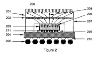
- FIG. 2 shows a device 200 according to this invention.
- the device 200 comprises an electronic component (shown as an integrated circuit (IC) chip) 203 mounted to a substrate 204 through a die attach adhesive 209 containing spacers 211.
- the substrate 204 has solder balls 205 attached thereto through pads 210.
- a first interface material (TIM1) 206 is interposed between the IC chip 203 and a metal cover 207.
- the metal cover 207 acts as a heat spreader.
- a second interface material (TIM2) 202 is interposed between the metal cover 207 and a heat sink 201. Heat moves along a thermal path represented by arrows 208 when the device is operated.
- Products and devices may be prepared including the PCC described above.
- the PCC described above may be used as the thermally conductive interface materials in the devices disclosed in U.S. Patents 5,912,805 ; 5,930,893 ; 5,950,066 ; 6,054,198 ; and 6,286,212 in addition to, or instead of, the interface materials described therein.
- the silicone-organic block copolymer may provide more than one phase change temperature to the PCC.
- PCCs with multiple phase change temperatures can be advantageous in providing resistance to pump-out at operating temperature of an electronic device in which the PCC is used as a TIM.
- a silicone-organic block copolymer can be selected with at least two phase change temperatures, with two of the phase change temperatures being such that the operating temperature of an electronic component, such as an integrated circuit, is between the two phase change temperatures.
- a device as described above can be assembled at a temperature above the higher phase change temperature, where viscosity of the PCC is lowest and the PCC is most compliant.
- Example 6 shows a silicone-organic block copolymer having more than one phase change temperature.
- Undecylenic acid (Cashem Corporation) is purified by vacuum distillation at 180-210°C.
- a 1000 milliliter (ml) round bottom flask equipped with a thermometer, electrical stirrer, nitrogen sweep, and a condenser is charged with 153.5 grams (g) of a solution of 70% hexamethylene diamine and 30% water (E. I. Du Pont de Nemours and Company, Inc., of Wilmington, Delaware, U.S.A.) and 346.5 g of the purified undecylenic acid.
- the flask is heated to 120°C and is maintained at this temperature for about 1 hour.
- the flask is heated to 160°C to form the amide, with water generated as the reaction by-product.
- the reaction is allowed to continue at this temperature for 1 hour or until water is no longer detected in the condenser trap, indicating the reaction is complete.
- the flask is then heated to 220°C for 1 hour and is further heated to 240°C for 2 hours under vacuum with a low nitrogen purge to strip out impurities.
- the reaction mixture is then cooled and collected in an aluminum foil lined pan.
- a 5000 ml three neck flask equipped with a thermometer, electrical stirrer and a condenser is charged with 2978.4 g of dimethylcyclosiloxanes, 21.52 g of tetramethyldihydrogen disiloxane and 1.4 g of trifluoromethane sulfonic acid.
- the flask is heated to 90°C and is kept at this temperature for 4 hours. After 4 hours, 70 g of sodium bicarbonate is added. The heat is turned off, and the content of the flask is allowed to cool to room temperature and is mixed for 12 hours.
- the reaction mixture is filtered and transferred to a clean 5000 ml three neck flask equipped with a thermometer, electrical stirrer and a condenser.
- the flask is heated to 150°C and is vacuum stripped.
- the level of functional SiH in the siloxane is then measured by infrared spectroscopy.
- the resulting product is 250 DP dimethylhydrogen endblocked polydimethylsiloxane. (DP means degree of polymerization.)
- a 1000 ml, three neck, round bottom flask equipped with a temperature probe, an electrical stirrer, and a condenser is charged with 10 g of the amide formed as described above, 300 g xylene, and 0.107 g of 1,3-diethenyl-1,1,3,3-tetramethyldisiloxane platinum complex in dimethyl siloxane.
- the flask is heated to 115°C, and 294.93 g of 250 DP dimethylhydrogen endblocked polydimethyl siloxane is then added dropwise via an addition funnel. Following the addition, the reactants are mixed for 1 hour.
- the flask is then heated to 150°C and is vacuum stripped to ensure removal of all residual solvent.
- the resulting copolymer has number average molecular weight (M n ) of 50981 and weight average molecular weight (M w ) of 129,900 as measured by Gel Permeation Chromatography GPC (calibrated against polystyrene standards). Measurement of dynamic storage modulus (G'), dynamic loss modulus (G"), and complex viscosity (Eta*) as a function of temperature are obtained on an Advanced Rheometric Expansion System (ARES) Rheometer from Rheometric Scientific. At 30°C the copolymer is a soft flexible solid with a G' and G" of 1.05 ⁇ 10 6 and 1.23 ⁇ 10 5 dynes/cm 2 , respectively. The copolymer exhibits a phase transition temperature at 95°C, and the complex viscosity is measured in the melt state (120°C) at 368 Poise.
- G n number average molecular weight
- M w weight average molecular weight
- GPC Gel Permeation Chromatography G
- Example 2 Forming a PCC with the Silicone-organic Block Copolymer of Example 1
- the copolymer of Example 1 is combined with Al 2 O 3 filler (1:1 mixture of CB-A20S and A1-43-Me aluminum oxide fillers from Showa-Denko K.K.) by heating the copolymer and filler above 100°C and centrifugal mixing.
- a PCC is prepared with 88.2 weight % filler loading. Measurement on an ARES rheometer of the PCC indicates a softening transition temperature at about 85°C.
- the PCC is fabricated between 2 release liner films in hot press at 150°C to provide a flexible coherent film with a thickness of approximately 150 micrometers (6 mil).
- the change in bondline thickness is measured as a function of pressure between 2 silicon wafer substrates at 100°C.
- PCCs are prepared as in Example 2, except that different filler loadings are used. Thermal conductivity is measured as a function of filler loading on the Mathis Hot Disk equipment according to the method of Reference Example 1. The results are in Table 2 below. Table 2 Example 3 Example 4 Temperature Thermal Conductivity (W/m°K) (°C) 60 vol% filler 65 vol% filler 25 2.14 2.46 40 1.97 2.53 60 1.88 2.40 80 1.92 2.10 100 1.75 2.02 120 1.64 2.01 60 and 65 vol.% correspond to 85.6 and 88.1 weight % filler loading, respectively. W/m °K means Watts per meter-Kelvin.
- Undecylenic acid (Cashem Corporation) is purified by vacuum distillation at 180-210°C.
- a 500 milliliter (ml) round bottom flask equipped with a thermometer, electrical stirrer, nitrogen sweep, and a condenser is charged with 46.8 grams (g) of 2-methyl-1,5 pentane diamine (Dupont Dytec A Amine purchased through Aldrich) and 150.1 g of purified undecylenic acid.
- the flask is heated to 120°C and is maintained at this temperature for about 1 hour. Next, the material is heated to 180°C, and the amide is produced with water as the reaction by-product.
- the reaction is allowed to continue at this temperature for 1 hour or until water is no longer detected in the condenser trap indicating the reaction is complete.
- the flask is then heated to 220°C for 2 hours and is further heated to 240°C for 2 hours under vacuum with a low nitrogen purge to strip out impurities.
- the reaction mixture is then cooled and is collected in an aluminum foil lined pan.
- a 500 ml, three neck, round bottom flask equipped with a temperature probe, an electrical stirrer, and a condenser is charged with 10 g of the amide formed as described above, 200 g toluene, and 0.2 g 1,3-diethenyl-1,1,3,3-tetramethyldisiloxane platinum complex in dimethyl siloxane.
- the flask is heated to 115°C and 176.3 g of 250 DP dimethylhydrogen endblocked polydimethylsiloxane (as in Example 1) is then added drop-wise via an addition funnel. Following the addition, the reactants are further allowed to mix for 1 hour.
- the flask is then heated to 150°C and vacuum stripped to ensure removal of all residual solvent
- the resulting copolymer has M n of 17380 and M w of 56970 as measured by gel permeation chromatograph (GPC).
- GPC gel permeation chromatograph
- a dynamic temperature ramp test of the copolymer on an ARES Rheometer reveals a phase transition temperature of about 45°C.
- the copolymer is a flexible solid with a G' and G" of 3.23 ⁇ 10 6 and 5.78 ⁇ 10 5 dynes/cm 2 , respectively.
- the melt viscosity at 120°C is 19 Poise.
- a 1000 ml, three neck, round bottom flask equipped with a temperature probe, an electrical stirrer, and a condenser is charged with 1.26 g of the amide described in Example 1 and 3.76 g of amide described in Example 5, 100 g toluene, and 0.24 g 1,3-diethenyl-1,1,3,3-tetramethyldisiloxane platinum complex in dimethyl siloxane.
- the flask is heated to 115°C and 88.28 g 250 DP dimethylhydrogen endblocked polydimethylsiloxane (as in Example 1) is added drop-wise via an addition funnel. Following the addition, the reactants are further allowed to mix for 1 hour.
- the flask is then heated to 150°C and vacuum stripped to ensure removal of all residual solvent.
- the resulting polymer has M n of 20080 and M w of 51190 as measured by GPC (calibrated against polystyrene standards).
- a temperature-viscosity sweep of the copolymer on an ARES Rheometer provides two phase transition temperature at 45 and 85°C. At 30°C the copolymer is a flexible solid with a measured G' and G" of 3.93 ⁇ 10 6 and 6.58 ⁇ 10 5 dynes/cm 2 , respectively. Above the phase transition temperature, the melt viscosity at 120°C is 29 Poise.
- Undecylenic acid (Cashem Corporation) is purified by vacuum distillation at 180-210°C.
- a 500 milliliter (ml) round bottom flask equipped with a thermometer, electrical stirrer, nitrogen sweep, and a condenser is charged with 40 grams (g) of 2-methyl-1,5 pentane diamine (Dupont Dytec A Amine purchased through Aldrich) and is purged for about 5 minutes to remove any oxygen in the headspace. With the stirring off, 10.10 g of adipic acid (Dupont, Adipure Grade) is added. The electrical stirrer is then turned on, and the mixture turns to a light yellow color. Next, 101.53 g of the purified undecylenic acid is slowly added to the reaction mixture.
- the flask is heated to 135°C and is maintained at this temperature for about 1 hour.
- the material is heated to 170°C, and the amide is produced with water as the reaction by-product.
- the flask is then heated to 220°C for 2 hours and is further heated to 240°C for 2 hours under vacuum with a low nitrogen purge to strip out impurities.
- the reaction mixture is then cooled and is collected in an aluminum foil lined pan.
- a 1000 ml, three neck, round bottom flask equipped with a temperature probe, an electrical stirrer, and a condenser is charged with 5.09 g of the amide formed as described above, 100.75 g toluene, and 0.4 g 1,3-diethenyl-1,1,3,3-tetramethyldisiloxane platinum complex in dimethyl siloxane.
- the flask is heated to 115°C and 96.46 g of 250 DP dimethylhydrogen endblocked polydimethylsiloxane (as in Example 1) is then added drop-wise via an addition funnel. Following the addition, the reactants are mixed for 1 hour. The flask is then heated to 150°C and vacuum stripped to ensure removal of all residual solvent.
- the resulting silicone-amide block copolymer has M n of 21,270 and M w of 64,360 as measured by gel permeation chromatograph (GPC).
- GPC gel permeation chromatograph
- a dynamic temperature ramp test of the copolymer on an ARES Rheometer reveals a phase change temperature of 67°C.
- the copolymer is a flexible solid with a G' and G" of 1.63 ⁇ 10 6 and 5.30 ⁇ 10 5 dynes/cm 2 , respectively.
- the melt viscosity at 120°C is 63 Poise.
Abstract
Description
- This invention relates to a thermally conductive phase change composition (PCC) and methods for preparation and use of the PCC. More particularly, this invention relates to a PCC comprising an silicone-organic block copolymer and a thermally conductive filler. The PCC can be used as a thermal interface material (TIM).
- Electronic components such as semiconductors, transistors, integrated circuits (ICs), discrete devices, and others known in the art are designed to operate at a normal operating temperature or within a normal operating temperature range. However, the operation of an electronic component generates heat. If sufficient heat is not removed, the electronic component will operate at a temperature significantly above its normal operating temperature. Excessive temperatures can adversely affect performance of the electronic component and operation of the device associated therewith and negatively impact mean time between failures.
- To avoid these problems, heat can be removed by thermal conduction from the electronic component to a heat sink. The heat sink can then be cooled by any convenient means such as convection or radiation techniques. During thermal conduction, heat can be transferred from the electronic component to the heat sink by surface contact between the electronic component and the heat sink or by contact of the electronic component and heat sink with a TIM. The lower the thermal impedance of the medium, the greater the flow of heat from the electronic component to the heat sink.
- Surfaces of the electronic component and the heat sink are typically not completely smooth, therefore, it is difficult to achieve full contact between the surfaces. Air spaces, which are poor thermal conductors, appear between the surfaces and increase impedance. These spaces can be filled by inserting a TIM between the surfaces.
- Some commercially available TIMs are organic polymers or elastomers filled with thermally conductive fillers. However, elastomers suffer from the drawbacks that they may be difficult to apply in an uncured state, and they may not fully adhere or mesh with the surfaces if cured before application. Polymers suffer from the drawback that they can flow out of the spaces after application. Some polymers may also suffer from the drawback that they lack sufficient thermal conductivity.
- Silicone greases with conductive fillers have also been proposed as TIMs. However, greases suffer from the drawbacks that they can be messy to apply and can flow out of the spaces after application.
- PCCs have been proposed for use as TIMs. PCCs are advantageous in solving the above problems because they can be formulated to be a solid at low temperatures and deformable at a phase change temperature. The phase change temperature can be equal to or above the normal operating temperature of the electronic component.
- PCCs can comprise organic materials such as waxes, and conductive fillers. However, organic waxes suffer from the drawback that they can flow out of the spaces after application, during operation of the electronic component. Organic waxes may also be brittle at room temperature.
- This invention relates to a phase change composition (PCC) and methods for its preparation and use. The PCC comprises a matrix and a thermally conductive filler. The matrix comprises a silicone-organic block copolymer.
- Figure 1 is an interface material according to this invention.
- Figure 2 is a device according to this invention.
-
- 100
- interface material
- 101
- substrate
- 102
- layers of PCC
- 103
- release liners
- 200
- device
- 203
- electronic component (shown as an integrated circuit chip)
- 204
- substrate
- 209
- die attach adhesive
- 211
- spacers
- 205
- solder balls
- 210
- pads
- 206
- first interface material (TIM1)
- 207
- metal cover acting as a heat spreader
- 202
- second interface material (TIM2)
- 208
- thermal path represented by arrows
- All amounts, ratios, and percentages are by weight unless otherwise indicated. The following is a list of definitions, as used herein.
- "A" and "an" each mean one or more.
- "Alkyl" means a saturated hydrocarbon group.
- "Combination" means two or more items put together by any method.
- "Copolymer" means a polymer made from at least two distinct monomers. Copolymer includes, but is not limited to, polymers made from only two distinct monomers.
- "Phase change temperature" means a temperature or temperature range evidencing a transition from a solid, crystalline, or glassy phase to a semi-solid phase, which can be characterized as exhibiting intermolecular chain rotation.
- "Silicone-organic block copolymer" means a material having at least one Si-O-SiR-Si linkage in its backbone, where R represents an organic group.
- "Substituted" means one or more hydrogen atoms bonded to a carbon atom has been replaced with another substituent.
- "Surface treated" means that all, or a portion of, reactive groups on a filler particle have been rendered less reactive by any convenient chemical or unreactive means.
- This invention relates to a phase change composition (PCC). The PCC comprises:
- A) a matrix comprising a silicone-organic block copolymer,
- B) a thermally conductive filler,
- optionally C) a treating agent, and
- optionally D) an antioxidant.
- Component A) is a matrix that binds the components in the PCC. Component A) comprises a silicone-organic block copolymer. The PCC can comprise at least 4%, alternatively at least 5% of component A). The PCC can comprise up to 60% of component A), alternatively up to 50%, alternatively up to 20%, alternatively up to 10%. Silicone-organic block copolymers are known in the art and commercially available.
- Suitable silicone-organic block copolymers include silicone acrylate block copolymers, silicone-amide block copolymers, silicone-epoxy block copolymers, silicone-ether block copolymers, silicone-imide block copolymers, silicone-styrene block copolymers, silicone-urethane block copolymers, silicone-urea block copolymers, silicone-vinylether block copolymers, combinations thereof, and others. Silicone-organic block copolymers and methods for their preparation are known in the art, see for example, Bogdan C. Simionescu,Valeria Harabagiu and Cristofor I. Simionescu, "Siloxane-Containing Polymers" in The Polymeric Materials Encyclopedia, CRC Press, Inc., 1996; James E. McGrath, "Research on Thermoplastic Elastomers" in Thermoplastic Elastomers, A Comprehensive Review, Edited by N.R. Legge, G. Holden, H.E. Schroeder, Hanser Publishers, 1987; Bruce Hardman and Arnold Torkelson, "Silicones" in Encyclopedia of Polymer Science and Engineering, Edited by H.F. Mark, N.M. Bikales, C.G. Overberger, G. Menges, J.I. Kroschwitz, John Wiley & Sons, 1989, vol. 15, page 243; and I. Yilgor, J. S. Riffle, G. L. Wilkes and J. E. McGrath, "Polymer Bulletin", 8, 535-542 (1982). Silicone-organic block copolymers and methods for their preparation can also be found in
U.S. Patents Re.33,141 ;4,558,110 ;4,631,329 ; and4,793,555 . Silicone-urethane block copolymers and silicone-amide block copolymers and methods for their preparation are disclosed inU.S. Patents 4,501,861 ;4,604,442 ;5,981,680 ; and6,051,216 . - Silicone-amide block copolymers are exemplified by those comprising units of

- Subscript n represents an average value for degree of polymerization of the siloxane units as shown in Formula I with this average being a number average based on all the siloxane segments in all units in Formula I. Variation in individual n values is possible. Subscript n is at least 1, alternatively at least 10, alternatively at least 12, alternatively at least 15. Subscript n is up to 700, alternatively up to 500, alternatively up to 50, alternatively up to 45, alternatively up to 30, alternatively up to 18.
- Subscript m is at least 1, alternatively at least 4, alternatively at least 45, alternatively at least 55, alternatively at least 60. Subscript m can be up to 300, alternatively up to 200, alternatively up to 125, alternatively up to 80. Without wishing to be bound by theory, it is thought that increasing the value of m increases the melt viscosity of the silicone-organic block copolymer, and consequently the melt viscosity of the PCC (the viscosity of the PCC when heated above its phase change temperature). The upper limit of m may be limited to a value that provides a melt viscosity that allows the PCC to comply and wet-out the substrate on which the PCC will be applied under operating temperature and pressure conditions.
- X is a divalent hydrocarbon group. X may be branched or linear. X may be saturated. X has at least 1 carbon atom, alternatively at least 3 carbon atoms. X can have up to 30 carbon atoms, alternatively up to 10 carbon atoms.
- X1 is a divalent organic group. X1 can be a divalent hydrocarbon group. Divalent hydrocarbon groups for X1 can be branched or linear. Divalent hydrocarbon groups for X1 have at least 1 carbon atom, alternatively at least 2 carbon atoms. Divalent hydrocarbon groups for X1 have up to 40 carbon atoms, alternatively up to 20 carbon atoms, alternatively up to 10 carbon atoms, alternatively up to 6 carbon atoms.
- Divalent hydrocarbon groups for X1 may be unsubstituted or substituted. Divalent hydrocarbon groups for X1 may be substituted by, for example, at least one of (i) hydroxy; (ii) a cycloalkyl group of 3 to 8 carbon atoms; (iii) 1 to 3 members each independently selected from alkyl groups of 1 to 3 carbon atoms, unsubstituted phenyl groups, and phenyl groups substituted by 1 to 3 members each independently selected from alkyl groups of 1 to 3 carbon atoms; (iv) a hydroxyalkyl group of 1 to 3 carbon atoms; and (v) an alkyl amino group of 1 to 6 carbon atoms.
- Divalent organic groups for X1 may comprise a hydrocarbon chain containing at least one of (i) 1 to 3 amide linkages; (ii) a cyclic, divalent, saturated hydrocarbon group of 5 or 6 carbon atoms; and (iii) a phenylene optionally substituted by 1 to 3 members selected each independently from alkyl groups of 1 to 3 carbon atoms.
- X1 can be a group of the formula R20T(R21)R22, where R20 and R22 are divalent hydrocarbon groups of 1 to 10 carbon atoms and R21 is a monovalent or divalent hydrocarbon group of 1 to 10 carbon atoms, such groups being independent of one another, and T is C(R), where R can be hydrogen, R1, R2, R3, R4, or a trivalent N, P or Al; the divalencies and trivalencies herein should be understood and taken to allow for branching, cross linking or the like in certain instances and as appropriate.
- Each of R1, R2, R3, and R4 is independently methyl, ethyl, propyl, isopropyl, a halogenated alkyl group such as trifluoropropyl, a chain comprising siloxane (such as a polydimethylsiloxane or a siloxane based polyamide), and phenyl, wherein the phenyl may optionally be substituted by 1 to 3 members independently selected from methyl and ethyl. Alternatively, each of R1, R2, R3, and R4 is selected from methyl and ethyl. Alternatively, each of R1, R2, R3, and R4 is methyl.
- The individual values for X, X1, n, R1, R2, R3, and R4 may be the same or different for each unit of the silicone-amide block copolymer (which may include those between any of the m units of Formula I). Such variation may or may not also exist for the X groups within each of the m units of Formula I. Individual X1 groups may be aliphatic, aromatic or both.
- When used in reference to Formula I, and unless otherwise indicated, the term "siloxane group" refers to a group having siloxane units such as:

- Acceptable variations of the Formula I include: (1) silicone-amide block copolymers in which multiple values of n, X, X1, R1, R2, R3, and R4 occur in one polymeric molecule (which may include variation between the m units of Formula I and even within X groups), wherein the sequencing of these units may be alternating, random or block; (2) silicone-amide block copolymers in which an organic triamine or higher amine such as tris(2-aminoethyl)amine replaces the organic diamine in part, to produce a branched or cross linked molecule; and (3) physical blends of any of (1) and (2) or alternating block copolymers, or combinations thereof.
- Formula I represents an alternating block copolymer or (AB)m type copolymer. Depending on how the copolymer of Formula I is endblocked, Formula I can represent a B(AB)m or a A(BA)m type copolymer. Formula I may be endblocked with an amide group, a tri-substituted silicone group, or both.
- Suitable silicone-amide block copolymers for use in this invention may also comprise units of Formula II:

- The silicone-amide block copolymers of Formula II can be prepared by modifying a diamide first using the condensation chemistry as described in
JP 63230781 WO 2001/68363 U.S. Patent 4,282,346 ; followed by the processes described above inU.S. Patents 5,981,680 and6,051,216 . Silicone-amide block copolymers of Formula II can be prepared by one of ordinary skill in the art without undue experimentation using the method set forth in Example 7, below by varying appropriate starting materials. - It should be understood that the disclosure of ranges herein should be taken not only to disclose the range itself but also anything subsumed therein, as well as endpoints. For example, disclosure of a range of 1 to 10 should be understood to disclose not only the range of 1 to 10, but also 1, 2.7, 9 and 10 individually, as well as any other number subsumed in the range. Similarly, disclosure of a range of hydrocarbons of 1 to 5 carbon atoms should be understood to disclose not only hydrocarbons of 1 to 5 carbon atoms as a class, but also hydrocarbons of 1 carbon atom, hydrocarbons of 2 carbon atoms, hydrocarbons of 3 carbon atoms, hydrocarbons of 4 carbon atoms and hydrocarbons of 5 carbon atoms individually.
- Without wishing to be bound by theory, it is thought that the silicone-organic block copolymers essentially form "thermoplastic gels." The organic ("hard") segments essentially serve as thermoplastic (reversible) crosslink sites and dictate the softening point or phase change temperature of the silicone-organic block copolymer, while the silicone ("soft") segments impart flexibility and elasticity. The ratios of hard and soft segments can be deliberately chosen such that the silicone-organic block copolymer is soft and more gel-like in character at room temperature as compared to a traditional thermoplastic elastomer. The architecture of the silicone-organic block copolymer chain, the chemical nature and length of the hard segments and the length of the soft segments affect the phase change temperature, the melt viscosity, and the room temperature modulus. It is also understood that other hard segments such as acrylates, epoxy, ester, ether, and others can be used in conjunction with the soft segments to form silicone-organic block copolymers with similar "thermoplastic gel" properties.
- Component B) is a thermally conductive filler. Component B) is dispersed in component A). The amount of component B) in the PCC depends various factors including the material selected for component A), the material selected for component B), and the desired phase change temperature of the PCC. The amount of component B) can be at least 40% of the PCC, alternatively at least 50% of the PCC, alternatively at least 85% of the PCC. The amount of component B) can be up to 96%, alternatively up to 95% of the PCC. If the amount of component B) is too low, the PCC may have insufficient thermal conductivity for some applications. The exact amount of thermally conductive filler for component B) will depend on various factors including the density and thermal conductivity of the thermally conductive filler selected.
- Component B) can be thermally conductive, electrically conductive, or both. Alternatively, component B) can be thermally conductive and electrically insulating. Suitable thermally conductive fillers for component B) include metal particles, metal oxide particles, and a combination thereof. Suitable thermally conductive fillers for component B) are exemplified by aluminum nitride; aluminum oxide; barium titinate; beryllium oxide; boron nitride; diamond; graphite; magnesium oxide; metal particulate such as copper, gold, nickel, or silver; silicon carbide; tungsten carbide; zinc oxide, a combination thereof, and others.
- Thermally conductive fillers are known in the art and commercially available, see for example,
U.S. Patent 6,169,142 (col. 4, lines 7-33). For example, CB-A20S and Al-43-Me are aluminum oxide fillers of differing particle sizes commercially available from Showa-Denko, and AA-04, AA-2, and AA18 are aluminum oxide fillers commercially available from Sumitomo Chemical Company. - Silver filler is commercially available from Metalor Technologies U.S.A. Corp. of Attleboro, Massachusetts, U.S.A. Boron nitride filler is commercially available from Advanced Ceramics Corporation, Cleveland, Ohio, U.S.A.
- The shape of the filler particles is not specifically restricted, however, rounded or spherical particles may prevent viscosity increase to an undesirable level upon high loading of the filler in the PCC.
- A combination of fillers having differing particle sizes and different particle size distributions may be used as component B). For example, it may be desirable to combine a first aluminum oxide having a larger average particle size with a second aluminum oxide having a smaller average particle size in a proportion meeting the closest packing theory distribution curve. This improves packing efficiency and may reduce viscosity and enhance heat transfer.
- The average particle size of the filler will depend on various factors including the type of filler selected for component B) and the exact amount added to the PCC, however, the filler can have an average particle size of at least 0.2 micrometers, alternatively at least 2 micrometers. The filler can have an average particle size of up to 80 micrometers, alternatively up to 50 micrometers.
- The filler for component B) may optionally be surface treated with component C) a treating agent. Treating agents and treating methods are known in the art, see for example,
U.S. Patent 6,169,142 (col. 4, line 42 to col. 5, line 2). - The PCC may comprise at least 0.05% of component C). The PCC may comprise up to 5%, alternatively up to 0.5%, of component C).
- The treating agent can be an alkoxysilane having the formula: R5 xSi(OR6)(4-x), where x is 1, 2, or 3; alternatively x is 3. R5 is a substituted or unsubstituted monovalent hydrocarbon group of at least 1 carbon atom, alternatively at least 8 carbon atoms. R5 has up to 50 carbon atoms, alternatively up to 30 carbon atoms, alternatively up to 18 carbon atoms. R5 is exemplified by alkyl groups such as hexyl, octyl, dodecyl, tetradecyl, hexadecyl, and octadecyl; and aromatic groups such as benzyl, phenyl and phenylethyl. R5 can be saturated or unsaturated, branched or unbranched, and unsubstituted. R5 can be saturated, unbranched, and unsubstituted.
- R6 is an unsubstituted, saturated hydrocarbon group of at least 1 carbon atom. R6 may have up to 4 carbon atoms, alternatively up to 2 carbon atoms. Component C) is exemplified by hexyltrimethoxysilane, octyltriethoxysilane, decyltrimethoxysilane, dodecyltrimethyoxysilane, tetradecyltrimethoxysilane, phenyltrimethoxysilane, phenylethyltrimethoxysilane, octadecyltrimethoxysilane, octadecyltriethoxysilane, a combination thereof, and others.
- Alkoxy-functional oligosiloxanes can also be used as treatment agents. Alkoxy-functional oligosiloxanes and methods for their preparation are known in the art, see for example,
EP 1 101 167 A2 . For example, suitable alkoxy-functional oligosiloxanes include those of the formula (R9O)dSi(OSiR7 2R8)4-d. In this formula, d is 1, 2, or 3, alternatively d is 3. Each R7 is can be independently selected from saturated and unsaturated monovalent hydrocarbon groups of 1 to 10 carbon atoms. Each R8 can be a saturated or unsaturated monovalent hydrocarbon group having at least 11 carbon atoms. Each R9 can be an alkyl group. - Metal fillers can be treated with alkylthiols such as octadecyl mercaptan and others, and fatty acids such as oleic acid, stearic acid, titanates, titanate coupling agents, zirconate coupling agents, a combination thereof, and others.
- Treatment agents for alumina or passivated aluminum nitride could include alkoxysilyl functional alkylmethyl polysiloxanes (e.g., partial hydrolysis condensate of R10 bR11 cSi(OR12)(4-b-c) or cohydrolysis condensates or mixtures), similar materials where the hydrolyzable group would be silazane, acyloxy or oximo. In all of these, a group tethered to Si, such as R10 in the formula above, is a long chain unsaturated monovalent hydrocarbon or monovalent aromatic-functional hydrocarbon. R11 is a monovalent hydrocarbon group, and R12 is a monovalent hydrocarbon group of 1 to 4 carbon atoms. In the formula above, b is 1, 2, or 3 and c is 0, 1, or 2, with the proviso that b + c is 1, 2, or 3. One skilled in the art could optimize a specific treatment to aid dispersion of the filler without undue experimentation.
- Component B), the thermally conductive filler, may optionally comprise a reinforcing filler in addition to the thermally conductive filler, or instead of a portion of the thermally conductive filler. The reinforcing filler can be a chopped fiber, such as chopped KEVLAR®. Without wishing to be bound by theory, it is thought that chopped KEVLAR® improves strength and coefficient of thermal expansion (CTE). Reinforcing fillers may also be treated with component C).
- Optional component D) is an antioxidant. Without wishing to be bound by theory, it is thought that component D) prevents chain cleavage of the silicone-organic block copolymer typically by scavenging free radicals. Component D) can comprise any antioxidant commonly used in plastics. Component D) can be added to the PCC in an amount of at least 0.001 %, alternatively at least 0.05% up to 1 %.
- Suitable antioxidants are known in the art and are commercially available. Suitable antioxidants include phenolic antioxidants and combinations of phenolic antioxidants with stabilizers. Phenolic antioxidants include fully sterically hindered phenols and partially hindered phenols. Stabilizers include organophosphorous derivatives such as trivalent organophosphorous compound, phosphites, phosphonates, and a combination thereof; thiosynergists such as organosulfur compounds including sulfides, dialkyldithiocarbamate, dithiodipropionates, and a combination thereof; and sterically hindered amines such as tetramethyl-piperidine derivatives. Suitable antioxidants and stabilizers are disclosed in Zweifel, Hans, "Effect of Stabilization of Polypropylene During Processing and Its Influence on Long-Term Behavior under Thermal Stress," Polymer Durability, Ciba-Geigy AG, Additives Division, CH-4002, Basel, Switzerland, American Chemical Society, vol. 25, pp. 375-396, 1996.
- Suitable phenolic antioxidants include vitamin E and IRGANOX® 1010 from Ciba Specialty Chemicals, U.S.A. IRGANOX® 1010 comprises pentaerythriol tetrakis(3-(3,5-di-t-butyl-4-hydroxyphenyl)propionate).
- Optional component E) is a catalyst inhibitor. Component E) can be an addition reaction catalyst inhibitor. Addition reaction catalyst inhibitors are known in the art and commercially available, see for example,
U.S. Patent 5,929,164 (col. 1, line 65 to col. 3, line 65). - Component E) can be a phosphine, a diphosphine, an amine, a diamine, a triamine, an organic sulfide, an alkenyl-functional compound, an alkynyl-functional compound, a hydroxy-functional compound, a combination thereof, or any other transition metal catalyst poison.
- Suitable phosphines include trialkyl phosphines and triaryl phosphines such as triphenyl phosphine. Suitable diphosphines include tetraphenylethylene diphosphine. Suitable amines include n-butyl amine and triethanolamine. Suitable diamines include tetramethylenediamine. Suitable organic sulfides include ethyl phenyl sulfide. Suitable alkenyl-functional compounds can be organic, organosilicones, or organosilanes. Suitable alkenyl-functional compounds include vinylsiloxanes and vinylsilanes. Suitable alkynyl functional compounds can be organic, such as acetylene, propyne, 1-butyne, 1-pentyne, 4,4-dimethyl-1-pentyne, 1-hexyne, 5-methyl-1-hexyne, and 1-decyne.
- Component E) is added in an amount sufficient to provide mechanical and chemical stability to the PCC for a period of at least 7 years when the PCC is to be used in a central processing unit (CPU) device. The amount of component E) can be at least 0.001 %. The amount of component E) can be up to 1%.
- Component F) is an optional matrix material that can be added in addition to component A) or instead of a portion of component A). Component F) can comprise a silicone resin. Without wishing to be bound by theory, it is thought that addition of a silicone resin would provide room temperature tack to the PCC, which may be advantageous for ease of application. Component F) can comprise a wax such as an organofunctional silicone wax that is compatible to some degree with the silicone-organic block copolymer.
- Component G) is a vehicle such as a solvent or diluent. Component G) can be added during preparation of the PCC, for example, to aid mixing and delivery. All or a portion of component G) may optionally be removed after the PCC is prepared.
- Component H) is a wetting agent.
- Component I) is an antifoaming agent.
- Component J) is a pigment.
- Component K) is a flame retardant.
- Component L) is a spacer. Spacers can comprise organic particles, inorganic particles, or a combination thereof. Spacers can be thermally conductive, electrically conductive, or both. Spacers can have a particle size of at least 25 micrometers up to 250 micrometers. Spacers can comprise monodisperse beads. The amount of component L) depends on various factors including the distribution of particles, pressure to be applied during placement, temperature of placement, and others. The PCC can contain up to 15%, alternatively up to 5% of component L) added in addition to, or instead of, a portion of component B).
- Component M) is a low melting metal filler. The low melting metal filler can comprise In, Sn, or an alloy thereof. The low melting metal filler may optionally further comprise Ag, Bi, Cd, Cu, Ga, Pb, Sb, Zn, or a combination thereof. Examples of suitable low melting metal fillers include In-Bi-Sn alloys, Sn-In-Zn alloys, Sn-In-Ag alloys, Sn-Ag-Bi alloys, Sn-Bi-Cu-Ag alloys, Sn-Ag-Cu-Sb alloys, Sn-Ag-Cu alloys, Sn-Ag alloys, Sn-Ag-Cu-Zn alloys, and combinations thereof. The low melting metal filler can have a melting point higher than the melting point of the matrix. The low melting metal filler can have a melting point of up to 250 °C, alternatively up to 225 °C. The low melting metal filler can have a melting point of at least 50 °C, alternatively at least 150 °C. The low melting metal filler can be a eutectic alloy, a non-eutectic alloy, or a pure metal. Low melting metal fillers are known in the art and commercially available. Component M) can be added in addition to, or instead of, all or a portion of component B). The PCC may contain up to 96 % of component M).
- Component A) is selected such that the PCC will be solid below its phase change temperature and deformable at or above the phase change temperature. The phase change temperature can be selected depending on various factors including the use of the PCC.
- For example, the PCC can be used as a TIM in an electronic device. In this instance, the phase change temperature can be equal to or slightly less than the normal operating temperature for some electronic devices, e.g., at least 40 °C, alternatively at least 45 °C, alternatively at least 50 °C, alternatively at least 55 °C, alternatively at least 60 °C. The normal operating temperature can be up to 80 °C, alternatively up to 90 °C, alternatively up to 100 °C. Alternatively, the phase change temperature can be the maximum temperature the electronic devices can withstand, e.g., at least 150 °C up to 250 °C for some electronic devices.
- The PCC can be formulated to have a thermal conductivity of at least 1 Watts per meter Kelvin (W/mK), alternatively at least 3 W/mK, alternatively at least 5 W/mK. Thermal conductivity depends on various factors including the amount and type of filler selected for component B).
- The PCC can be prepared by any convenient means, such as mixing all components at a temperature higher than the phase change temperature. For example, for PCCs having a phase change temperature of up to 90 °C, the PCC can be prepared by mixing all components at 100 °C.
- When component C) is present, the PCC may optionally be prepared by surface treating component B) with component C) and thereafter mixing the PCC at a temperature above the phase change temperature. Alternatively, component C) may be mixed with some or all of the other components simultaneously at a temperature above the phase change temperature.
- When component G) is present, the PCC can be prepared by mixing all components at ambient or elevated temperature.
- The PCC described above can be used as an interface material, such as a thermal interface material (TIM). The interface material may have any convenient configuration, and one skilled in the art would be able to control the configuration by appropriate selection of component A), and other components. The PCC can be formulated to be form stable under ambient conditions. The PCC can be formulated to be self-supporting under ambient conditions. The PCC may optionally be provided as a flat member, such as a pad, tablet, sheet, or tape. Alternatively, the PCC may be provided as a hemispherical nubbin, a convex member, a pyramid, or a cone. The PCC may be formulated to be a tacky or tack-free solid under ambient conditions.
- The PCC may optionally have a removable release sheet over a surface of the PCC. A release sheet can be used when the PCC is tacky at ambient conditions. The release sheet can be, for example, a wax- or silicone-coated paper or plastic sheet having a relatively low surface energy. The PCC may be applied to a face stock, liner, or other release sheet by any conventional means such as a direct process, e.g., spray-coating, knife-coating, roller coating, casting, drum coating, dipping or the like or an indirect transfer process using a release sheet. A solvent, diluent, or other vehicle may be added to the PCC before application, and thereafter the vehicle is removed to leave an adherent film, coating, or residue of the PCC on the release sheet.
- The PCC may optionally be coated on a substrate, for example, when the PCC lacks sufficient form stability during processing. The substrate can be a thermally conductive material, an electrically conductive material, or both. The substrate can be, for example, a metal foil or perforated metal foil, such as gold, silver, copper, or aluminum foil; polyimide; polyamide; KAPTON® from E. I. Du Pont de Nemours and Company, Inc., of Wilmington, Delaware, U.S.A.; or polyethylene terephthalate polyester (MYLAR® from E. I. Du Pont de Nemours and Company, Inc., of Wilmington, Delaware, U.S.A.). The PCC can be coated on one or more surfaces of the substrate. Release sheets may be used on both sides of the coated substrate. This interface material is shown in figure 1. In figure 1, the
interface material 100 comprises asubstrate 101, and layers of the PCC described above 102 formed on opposing sides of thesubstrate 101.Release liners 103 are applied over the exposed surfaces of thePCC 102. - Various interface materials comprising the PCC described above can be prepared. The PCC described above can be used to prepare interface materials by various methods, including those disclosed in
U.S. Patents 4,299,715 and5,904,796 . - The PCC can be interposed along a thermal path between a heat source a heat spreader. The PCC can be interposed by any convenient means, such as applying a form stable PCC or interface material comprising the PCC between the heat source and the heat spreader with or without an adhesive or primer, hot-melt dispensing the PCC, or solvent casting the PCC.
- The heat source can comprise an electronic component such as a semiconductor, a transistor, an integrated circuit, or a discrete device.
- The heat spreader can comprise a heat sink, a thermally conductive plate, a thermally conductive cover, a fan, a circulating coolant system, a combination thereof, or others. The PCC can be used in direct contact with the electronic component and the heat sink. The PCC can be applied either to the electronic component and thereafter the heat sink, or the PCC can be applied to the heat sink and thereafter to the electronic component.
- During or after interposing the PCC along the thermal path, the PCC can be heated to a temperature equal to or greater than the phase change temperature. Pressure may be applied. The PCC can then be cooled.
- This invention further relates to a product comprising:
- a) an electronic component,
- b) an interface material, and
- c) a heat sink;
- This invention further relates to a product comprising:
- a) a heat spreader, and
- b) an interface material on a surface of the heat spreader,
- Figure 2 shows a
device 200 according to this invention. Thedevice 200 comprises an electronic component (shown as an integrated circuit (IC) chip) 203 mounted to asubstrate 204 through a die attach adhesive 209 containingspacers 211. Thesubstrate 204 hassolder balls 205 attached thereto throughpads 210. A first interface material (TIM1) 206 is interposed between theIC chip 203 and ametal cover 207. Themetal cover 207 acts as a heat spreader. A second interface material (TIM2) 202 is interposed between themetal cover 207 and aheat sink 201. Heat moves along a thermal path represented byarrows 208 when the device is operated. - Products and devices may be prepared including the PCC described above. For example, the PCC described above may be used as the thermally conductive interface materials in the devices disclosed in
U.S. Patents 5,912,805 ;5,930,893 ;5,950,066 ;6,054,198 ; and6,286,212 in addition to, or instead of, the interface materials described therein. - Depending the chemical nature of the organic groups and the architecture of the silicone-organic block copolymer chain, the silicone-organic block copolymer may provide more than one phase change temperature to the PCC. PCCs with multiple phase change temperatures can be advantageous in providing resistance to pump-out at operating temperature of an electronic device in which the PCC is used as a TIM. For example, a silicone-organic block copolymer can be selected with at least two phase change temperatures, with two of the phase change temperatures being such that the operating temperature of an electronic component, such as an integrated circuit, is between the two phase change temperatures. A device as described above can be assembled at a temperature above the higher phase change temperature, where viscosity of the PCC is lowest and the PCC is most compliant. At the operating temperature, the PCC would be deemed semi-solid, thereby providing some degree of compliancy so that the PCC does not crack, delaminate, or transfer compressive pressure on the integrated circuit, but the PCC would still have stability against pump-out. Example 6 shows a silicone-organic block copolymer having more than one phase change temperature.
- These examples are intended to illustrate the invention to one skilled in the art and should not be interpreted as limiting the scope of the invention set forth in the claims.
- Thermal conductivity measurement of the phase change materials is carried out on the Mathis Hotdisk equipment. Technical details of the method can be found in the instrument menu from the Mathis Instrument LTD. The technique can also be found in a publication by Craig Dixon, Michael Strong, and S. Mark Zhang, Thermal Trends, Vol. 7, No. 5, page 1.
- Undecylenic acid (Cashem Corporation) is purified by vacuum distillation at 180-210°C. A 1000 milliliter (ml) round bottom flask equipped with a thermometer, electrical stirrer, nitrogen sweep, and a condenser is charged with 153.5 grams (g) of a solution of 70% hexamethylene diamine and 30% water (E. I. Du Pont de Nemours and Company, Inc., of Wilmington, Delaware, U.S.A.) and 346.5 g of the purified undecylenic acid. The flask is heated to 120°C and is maintained at this temperature for about 1 hour. Next, the flask is heated to 160°C to form the amide, with water generated as the reaction by-product. The reaction is allowed to continue at this temperature for 1 hour or until water is no longer detected in the condenser trap, indicating the reaction is complete. The flask is then heated to 220°C for 1 hour and is further heated to 240°C for 2 hours under vacuum with a low nitrogen purge to strip out impurities. The reaction mixture is then cooled and collected in an aluminum foil lined pan.
- A 5000 ml three neck flask equipped with a thermometer, electrical stirrer and a condenser is charged with 2978.4 g of dimethylcyclosiloxanes, 21.52 g of tetramethyldihydrogen disiloxane and 1.4 g of trifluoromethane sulfonic acid. The flask is heated to 90°C and is kept at this temperature for 4 hours. After 4 hours, 70 g of sodium bicarbonate is added. The heat is turned off, and the content of the flask is allowed to cool to room temperature and is mixed for 12 hours. The reaction mixture is filtered and transferred to a clean 5000 ml three neck flask equipped with a thermometer, electrical stirrer and a condenser. The flask is heated to 150°C and is vacuum stripped. The level of functional SiH in the siloxane is then measured by infrared spectroscopy. The resulting product is 250 DP dimethylhydrogen endblocked polydimethylsiloxane. (DP means degree of polymerization.)
- A 1000 ml, three neck, round bottom flask equipped with a temperature probe, an electrical stirrer, and a condenser is charged with 10 g of the amide formed as described above, 300 g xylene, and 0.107 g of 1,3-diethenyl-1,1,3,3-tetramethyldisiloxane platinum complex in dimethyl siloxane. The flask is heated to 115°C, and 294.93 g of 250 DP dimethylhydrogen endblocked polydimethyl siloxane is then added dropwise via an addition funnel. Following the addition, the reactants are mixed for 1 hour. The flask is then heated to 150°C and is vacuum stripped to ensure removal of all residual solvent.
- The resulting copolymer has number average molecular weight (Mn) of 50981 and weight average molecular weight (Mw) of 129,900 as measured by Gel Permeation Chromatography GPC (calibrated against polystyrene standards). Measurement of dynamic storage modulus (G'), dynamic loss modulus (G"), and complex viscosity (Eta*) as a function of temperature are obtained on an Advanced Rheometric Expansion System (ARES) Rheometer from Rheometric Scientific. At 30°C the copolymer is a soft flexible solid with a G' and G" of 1.05×10⁶ and 1.23×10⁵ dynes/cm2, respectively. The copolymer exhibits a phase transition temperature at 95°C, and the complex viscosity is measured in the melt state (120°C) at 368 Poise.
- The copolymer of Example 1 is combined with Al2O3 filler (1:1 mixture of CB-A20S and A1-43-Me aluminum oxide fillers from Showa-Denko K.K.) by heating the copolymer and filler above 100°C and centrifugal mixing.
- A PCC is prepared with 88.2 weight % filler loading. Measurement on an ARES rheometer of the PCC indicates a softening transition temperature at about 85°C.
- The PCC is fabricated between 2 release liner films in hot press at 150°C to provide a flexible coherent film with a thickness of approximately 150 micrometers (6 mil). The change in bondline thickness is measured as a function of pressure between 2 silicon wafer substrates at 100°C. These results are shown below. These results indicate that the PCC is capable of flowing under light pressures at temperatures above the softening transition temperature.
Table 1 Pressure (psi) Bondline Thickness (micrometers) 0.29 165 1.64 136 3.90 113 7.76 81 11.98 33 - PCCs are prepared as in Example 2, except that different filler loadings are used. Thermal conductivity is measured as a function of filler loading on the Mathis Hot Disk equipment according to the method of Reference Example 1. The results are in Table 2 below.
Table 2 Example 3 Example 4 Temperature Thermal Conductivity (W/m°K) (°C) 60 vol% filler 65 vol% filler 25 2.14 2.46 40 1.97 2.53 60 1.88 2.40 80 1.92 2.10 100 1.75 2.02 120 1.64 2.01 60 and 65 vol.% correspond to 85.6 and 88.1 weight % filler loading, respectively.
W/m °K means Watts per meter-Kelvin. - Undecylenic acid (Cashem Corporation) is purified by vacuum distillation at 180-210°C. A 500 milliliter (ml) round bottom flask equipped with a thermometer, electrical stirrer, nitrogen sweep, and a condenser is charged with 46.8 grams (g) of 2-methyl-1,5 pentane diamine (Dupont Dytec A Amine purchased through Aldrich) and 150.1 g of purified undecylenic acid. The flask is heated to 120°C and is maintained at this temperature for about 1 hour. Next, the material is heated to 180°C, and the amide is produced with water as the reaction by-product. The reaction is allowed to continue at this temperature for 1 hour or until water is no longer detected in the condenser trap indicating the reaction is complete. The flask is then heated to 220°C for 2 hours and is further heated to 240°C for 2 hours under vacuum with a low nitrogen purge to strip out impurities. The reaction mixture is then cooled and is collected in an aluminum foil lined pan.
- A 500 ml, three neck, round bottom flask equipped with a temperature probe, an electrical stirrer, and a condenser is charged with 10 g of the amide formed as described above, 200 g toluene, and 0.2 g 1,3-diethenyl-1,1,3,3-tetramethyldisiloxane platinum complex in dimethyl siloxane. The flask is heated to 115°C and 176.3 g of 250 DP dimethylhydrogen endblocked polydimethylsiloxane (as in Example 1) is then added drop-wise via an addition funnel. Following the addition, the reactants are further allowed to mix for 1 hour. The flask is then heated to 150°C and vacuum stripped to ensure removal of all residual solvent
- The resulting copolymer has Mn of 17380 and Mw of 56970 as measured by gel permeation chromatograph (GPC). A dynamic temperature ramp test of the copolymer on an ARES Rheometer reveals a phase transition temperature of about 45°C. At 30°C the copolymer is a flexible solid with a G' and G" of 3.23×10⁶ and 5.78×10⁵ dynes/cm2, respectively. The melt viscosity at 120°C is 19 Poise.
- A 1000 ml, three neck, round bottom flask equipped with a temperature probe, an electrical stirrer, and a condenser is charged with 1.26 g of the amide described in Example 1 and 3.76 g of amide described in Example 5, 100 g toluene, and 0.24 g 1,3-diethenyl-1,1,3,3-tetramethyldisiloxane platinum complex in dimethyl siloxane. The flask is heated to 115°C and 88.28 g 250 DP dimethylhydrogen endblocked polydimethylsiloxane (as in Example 1) is added drop-wise via an addition funnel. Following the addition, the reactants are further allowed to mix for 1 hour. The flask is then heated to 150°C and vacuum stripped to ensure removal of all residual solvent. The resulting polymer has Mn of 20080 and Mw of 51190 as measured by GPC (calibrated against polystyrene standards).
- A temperature-viscosity sweep of the copolymer on an ARES Rheometer provides two phase transition temperature at 45 and 85°C. At 30°C the copolymer is a flexible solid with a measured G' and G" of 3.93×10⁶ and 6.58×10⁵ dynes/cm2, respectively. Above the phase transition temperature, the melt viscosity at 120°C is 29 Poise.
- Undecylenic acid (Cashem Corporation) is purified by vacuum distillation at 180-210°C. A 500 milliliter (ml) round bottom flask equipped with a thermometer, electrical stirrer, nitrogen sweep, and a condenser is charged with 40 grams (g) of 2-methyl-1,5 pentane diamine (Dupont Dytec A Amine purchased through Aldrich) and is purged for about 5 minutes to remove any oxygen in the headspace. With the stirring off, 10.10 g of adipic acid (Dupont, Adipure Grade) is added. The electrical stirrer is then turned on, and the mixture turns to a light yellow color. Next, 101.53 g of the purified undecylenic acid is slowly added to the reaction mixture. The flask is heated to 135°C and is maintained at this temperature for about 1 hour. Next, the material is heated to 170°C, and the amide is produced with water as the reaction by-product. The flask is then heated to 220°C for 2 hours and is further heated to 240°C for 2 hours under vacuum with a low nitrogen purge to strip out impurities. The reaction mixture is then cooled and is collected in an aluminum foil lined pan.
- A 1000 ml, three neck, round bottom flask equipped with a temperature probe, an electrical stirrer, and a condenser is charged with 5.09 g of the amide formed as described above, 100.75 g toluene, and 0.4 g 1,3-diethenyl-1,1,3,3-tetramethyldisiloxane platinum complex in dimethyl siloxane. The flask is heated to 115°C and 96.46 g of 250 DP dimethylhydrogen endblocked polydimethylsiloxane (as in Example 1) is then added drop-wise via an addition funnel. Following the addition, the reactants are mixed for 1 hour. The flask is then heated to 150°C and vacuum stripped to ensure removal of all residual solvent.
- The resulting silicone-amide block copolymer has Mn of 21,270 and Mw of 64,360 as measured by gel permeation chromatograph (GPC). A dynamic temperature ramp test of the copolymer on an ARES Rheometer reveals a phase change temperature of 67°C. At 30°C the copolymer is a flexible solid with a G' and G" of 1.63×10⁶ and 5.30×10⁵ dynes/cm2, respectively. The melt viscosity at 120°C is 63 Poise.
Claims (15)
- A method comprising interposing a thermal interface material along a thermal path between a heat source and a heat spreader, wherea) the thermal interface material has at a first phase change temperature and a second phase change temperature, andb) the heat source has a normal operating temperature lower than the first phase change temperature and higher than the second phase change temperature.
- The method of claim 1, where the heat source comprises an electronic component.
- A composition comprising:A) a matrix comprising a silicone-organic block copolymer,B) a thermally conductive filler,optionally C) a treating agent, andoptionally D) an antioxidant.
- The composition of claim 3, where the composition has a phase change temperature of at least 40 °C.
- The composition of claim 3, where the silicone-organic block copolymer comprises a silicone acrylate block copolymer, a silicone-amide block copolymer, a silicone-epoxy block copolymer, a silicone-ester block copolymer, a silicone-ether block copolymer, a silicone-imide block copolymer, a silicone-styrene block copolymer, a silicone-urethane block copolymer, a silicone-urea block copolymer, a silicone-vinylether block copolymer, or a combination thereof.
- The composition of claim 3, where component B) comprises aluminum nitride, aluminum oxide, barium titinate, beryllium oxide, boron nitride, diamond, graphite, magnesium oxide, metal particulate, silicon carbide, tungsten carbide, zinc oxide, or a combination thereof.
- The composition of claim 3, where component C) is present and comprises an alkoxysilane having the formula: R5 xSi(OR6)(4-x), where
R5 is a substituted or unsubstituted monovalent hydrocarbon group of at least 1 carbon atoms and up to 50 carbon atoms,
each R6 is independently an unsubstituted, saturated hydrocarbon group of at least 1 carbon atom and up to 4 carbon atoms, and
x is 1, 2, or 3. - The composition of claim 3, where component D) is present and comprises a phenolic antioxidant or a combination of a phenolic antioxidant and a stabilizer.
- The composition of claim 3, further comprising an optional component comprising E) a catalyst inhibitor, a reinforcing filler; F) a silicone resin, a silicone wax, or a combination thereof; G) a vehicle; H) a wetting agent; I) an antifoaming agent; J) a pigment; K) a flame retardant; L) a spacer; M) a low melting metal filler, or a combination thereof.
- An interface material characterized by:I) the composition of claim 3, andII) a substrate, where the composition is coated on a surface of the substrate.
- The interface material of claim 10, where the substrate comprises a metal foil, a perforated metal foil, a polyamide sheet, a polyimide sheet, or a polyethylene terephthalate polyester sheet.
- The interface material of claim 11, where the composition is coated on two sides of the substrate.
- The interface material of claim 10, further comprising III) a release sheet covering a surface of the composition opposite the substrate.
- A device characterized by:a) a heat spreader, andb) an interface material on a surface of the heat spreader,where the interface material and the heat spreader are configured to comprise a portion of a thermally conductive path between an electronic component and a heat sink, and where the interface material comprises the composition of claim 3 or claim 4.
- A copolymer comprising units of formula:

n is at least 1,
n is up to 700,
m is at least 1,
m is up to 300,
a is at least 1,
a is up to 60,
X is a divalent hydrocarbon group,
X1 is a divalent organic group, and
each of R1, R2, R3, R4 is independently methyl, ethyl, propyl, isopropyl, a halogenated alkyl group, a chain comprising siloxane, and phenyl, where the phenyl may optionally be substituted by 1 to 3 members independently selected from methyl and ethyl.
Applications Claiming Priority (2)
| Application Number | Priority Date | Filing Date | Title |
|---|---|---|---|
| US10/122,526 US6815486B2 (en) | 2002-04-12 | 2002-04-12 | Thermally conductive phase change materials and methods for their preparation and use |
| EP03746543A EP1509572A2 (en) | 2002-04-12 | 2003-03-18 | Thermally conductive phase change materials |
Related Parent Applications (1)
| Application Number | Title | Priority Date | Filing Date |
|---|---|---|---|
| EP03746543A Division EP1509572A2 (en) | 2002-04-12 | 2003-03-18 | Thermally conductive phase change materials |
Publications (2)
| Publication Number | Publication Date |
|---|---|
| EP1783169A2 true EP1783169A2 (en) | 2007-05-09 |
| EP1783169A3 EP1783169A3 (en) | 2007-08-15 |
Family
ID=28790561
Family Applications (3)
| Application Number | Title | Priority Date | Filing Date |
|---|---|---|---|
| EP03746543A Withdrawn EP1509572A2 (en) | 2002-04-12 | 2003-03-18 | Thermally conductive phase change materials |
| EP06076876A Withdrawn EP1783169A3 (en) | 2002-04-12 | 2003-03-18 | Thermally conductive phase change materials |
| EP06076877A Expired - Lifetime EP1757659B1 (en) | 2002-04-12 | 2003-03-18 | Thermally conductive phase change materials |
Family Applications Before (1)
| Application Number | Title | Priority Date | Filing Date |
|---|---|---|---|
| EP03746543A Withdrawn EP1509572A2 (en) | 2002-04-12 | 2003-03-18 | Thermally conductive phase change materials |
Family Applications After (1)
| Application Number | Title | Priority Date | Filing Date |
|---|---|---|---|
| EP06076877A Expired - Lifetime EP1757659B1 (en) | 2002-04-12 | 2003-03-18 | Thermally conductive phase change materials |
Country Status (7)
| Country | Link |
|---|---|
| US (1) | US6815486B2 (en) |
| EP (3) | EP1509572A2 (en) |
| JP (1) | JP4628680B2 (en) |
| KR (3) | KR100987916B1 (en) |
| AU (1) | AU2003225830A1 (en) |
| TW (1) | TWI308170B (en) |
| WO (1) | WO2003087221A2 (en) |
Cited By (9)
| Publication number | Priority date | Publication date | Assignee | Title |
|---|---|---|---|---|
| DE102008004485A1 (en) | 2008-01-14 | 2009-07-16 | Bayerisches Zentrum für Angewandte Energieforschung e.V. | Covering of organic and inorganic phase change material, comprises introducing the phase change material into a porous, open-cellular carrier structure and providing the filled porous granulates with water vapor-tight layer |
| US8221910B2 (en) | 2008-07-16 | 2012-07-17 | Outlast Technologies, LLC | Thermal regulating building materials and other construction components containing polymeric phase change materials |
| US8404341B2 (en) | 2006-01-26 | 2013-03-26 | Outlast Technologies, LLC | Microcapsules and other containment structures for articles incorporating functional polymeric phase change materials |
| US8587945B1 (en) | 2012-07-27 | 2013-11-19 | Outlast Technologies Llc | Systems structures and materials for electronic device cooling |
| US8673448B2 (en) | 2011-03-04 | 2014-03-18 | Outlast Technologies Llc | Articles containing precisely branched functional polymeric phase change materials |
| US9234059B2 (en) | 2008-07-16 | 2016-01-12 | Outlast Technologies, LLC | Articles containing functional polymeric phase change materials and methods of manufacturing the same |
| US10003053B2 (en) | 2015-02-04 | 2018-06-19 | Global Web Horizons, Llc | Systems, structures and materials for electrochemical device thermal management |
| US10431858B2 (en) | 2015-02-04 | 2019-10-01 | Global Web Horizons, Llc | Systems, structures and materials for electrochemical device thermal management |
| USD911961S1 (en) | 2017-04-03 | 2021-03-02 | Latent Heat Solutions, Llc | Battery container |
Families Citing this family (64)
| Publication number | Priority date | Publication date | Assignee | Title |
|---|---|---|---|---|
| US20040217472A1 (en) * | 2001-02-16 | 2004-11-04 | Integral Technologies, Inc. | Low cost chip carrier with integrated antenna, heat sink, or EMI shielding functions manufactured from conductive loaded resin-based materials |
| US20030168731A1 (en) * | 2002-03-11 | 2003-09-11 | Matayabas James Christopher | Thermal interface material and method of fabricating the same |
| US6791832B2 (en) * | 2002-03-26 | 2004-09-14 | Intel Corporation | Electronic package |
| US6791839B2 (en) * | 2002-06-25 | 2004-09-14 | Dow Corning Corporation | Thermal interface materials and methods for their preparation and use |
| AU2003256933A1 (en) | 2002-07-26 | 2004-02-16 | E.I. Du Pont De Nemours And Company | Improved thermoplastic polymeric ovenware |
| US8974915B2 (en) * | 2004-03-16 | 2015-03-10 | Rensselaer Polytechnic Institute | Block copolymer and nanofiller composites |
| EP1807734B1 (en) * | 2004-10-08 | 2011-11-09 | Dow Corning Corporation | Lithography processes using phase change compositions |
| DE602005023531D1 (en) * | 2004-12-16 | 2010-10-21 | Dow Corning | AMIDSUBSTITUTED SILICONE AND METHOD FOR THE PRODUCTION AND USE THEREOF |
| ATE526365T1 (en) | 2004-12-23 | 2011-10-15 | Dow Corning | CROSS-LINKABLE SACCHARIDE-SILOXANE COMPOSITIONS AND NETWORKS, COATINGS AND ARTICLES FORMED THEREFROM |
| US20060228542A1 (en) * | 2005-04-08 | 2006-10-12 | Saint-Gobain Performance Plastics Corporation | Thermal interface material having spheroidal particulate filler |
| JP4534062B2 (en) | 2005-04-19 | 2010-09-01 | ルネサスエレクトロニクス株式会社 | Semiconductor device |
| JP5122444B2 (en) | 2005-05-23 | 2013-01-16 | ダウ・コーニング・コーポレイション | Personal care compositions comprising saccharide-siloxane copolymers |
| US20070031684A1 (en) * | 2005-08-03 | 2007-02-08 | Anderson Jeffrey T | Thermally conductive grease |
| US20070032610A1 (en) * | 2005-08-08 | 2007-02-08 | General Electric Company | Energy responsive composition and associated method |
| US7761181B2 (en) * | 2005-11-29 | 2010-07-20 | The Boeing Company | Line replaceable systems and methods |
| TWI291480B (en) * | 2005-12-20 | 2007-12-21 | Ind Tech Res Inst | Composition for thermal interface materials |
| CN101346649B (en) * | 2005-12-23 | 2010-09-01 | 3M创新有限公司 | Films including thermoplastic silicone block copolymers |
| WO2007075900A2 (en) * | 2005-12-23 | 2007-07-05 | 3M Innovative Properties Company | Multilayer films including thermoplastic silicone block copolymers |
| US20070173154A1 (en) * | 2006-01-26 | 2007-07-26 | Outlast Technologies, Inc. | Coated articles formed of microcapsules with reactive functional groups |
| US20100012883A1 (en) * | 2008-07-16 | 2010-01-21 | Outlast Technologies, Inc. | Functional Polymeric Phase Change Materials |
| KR101460980B1 (en) * | 2006-05-23 | 2014-11-13 | 다우 코닝 코포레이션 | Novel silicone film former for delivery of actives |
| KR101547343B1 (en) * | 2007-02-20 | 2015-08-28 | 다우 코닝 코포레이션 | Filler treating agents based on hydrogen bonding polyorganosiloxanes |
| EP2188834A4 (en) * | 2007-09-11 | 2014-03-19 | Dow Corning | Composite, thermal interface material containing the composite, and methods for their preparation and use |
| CN101803010B (en) * | 2007-09-11 | 2014-01-29 | 陶氏康宁公司 | Thermal interface material, electronic device containing the thermal interface material, and methods for their preparation and use |
| WO2009063570A1 (en) * | 2007-11-16 | 2009-05-22 | Fujitsu Limited | Electronic device and its manufacturing method |
| US20090208722A1 (en) * | 2008-02-18 | 2009-08-20 | John Francis Timmerman | Oriented Members for Thermally Conductive Interface Structures |
| US20090321922A1 (en) * | 2008-06-30 | 2009-12-31 | Ravi Shankar | Self-healing thermal interface materials for semiconductor packages |
| US20100015430A1 (en) * | 2008-07-16 | 2010-01-21 | Outlast Technologies, Inc. | Heat Regulating Article With Moisture Enhanced Temperature Control |
| US9353304B2 (en) | 2009-03-02 | 2016-05-31 | Honeywell International Inc. | Thermal interface material and method of making and using the same |
| TWI389272B (en) * | 2009-04-22 | 2013-03-11 | Delta Electronics Inc | Heat dissipating module of electronic component and assembling method thereof |
| US8081468B2 (en) * | 2009-06-17 | 2011-12-20 | Laird Technologies, Inc. | Memory modules including compliant multilayered thermally-conductive interface assemblies |
| US20100321897A1 (en) * | 2009-06-17 | 2010-12-23 | Laird Technologies, Inc. | Compliant multilayered thermally-conductive interface assemblies |
| JP2013500352A (en) | 2009-07-24 | 2013-01-07 | ティコナ・エルエルシー | Thermally conductive polymer composition and articles made therefrom |
| US9090751B2 (en) | 2009-07-24 | 2015-07-28 | Ticona Llc | Thermally conductive thermoplastic resin compositions and related applications |
| CN103068887B (en) | 2010-08-23 | 2015-09-09 | 道康宁公司 | Sugared siloxanes stable in aqueous environments and the preparation and application of these sugared siloxanes |
| JP2013254901A (en) | 2012-06-08 | 2013-12-19 | Toshiba Corp | Sealing material and etching apparatus |
| US9084764B2 (en) | 2012-08-16 | 2015-07-21 | Exert Co. | Epidermal cooling |
| US10373891B2 (en) * | 2013-06-14 | 2019-08-06 | Laird Technologies, Inc. | Methods for establishing thermal joints between heat spreaders or lids and heat sources |
| US20140368992A1 (en) * | 2013-06-14 | 2014-12-18 | Laird Technologies, Inc. | Methods For Establishing Thermal Joints Between Heat Spreaders and Heat Generating Components Using Thermoplastic and/or Self-Healing Thermal Interface Materials |
| US10174433B2 (en) | 2013-12-05 | 2019-01-08 | Honeywell International Inc. | Stannous methanesulfonate solution with adjusted pH |
| JP2015230949A (en) * | 2014-06-04 | 2015-12-21 | 三菱電機株式会社 | Semiconductor device and manufacturing method of the same, and transfer sheet and manufacturing method of the same |
| CN106536609B (en) | 2014-07-07 | 2022-04-29 | 霍尼韦尔国际公司 | Thermal interface material with ion scavenger |
| WO2016083931A1 (en) | 2014-11-24 | 2016-06-02 | Sabic Global Technologies B.V. | Enclosure with a condensation-resistant interior surface |
| WO2016086410A1 (en) | 2014-12-05 | 2016-06-09 | Honeywell International Inc. | High performance thermal interface materials with low thermal impedance |
| US20160315030A1 (en) * | 2015-04-24 | 2016-10-27 | Laird Technologies, Inc. | Reusable thermoplastic thermal interface materials and methods for establishing thermal joints between heat sources and heat dissipating/removal structures |
| DE102015118245A1 (en) * | 2015-10-26 | 2017-04-27 | Infineon Technologies Austria Ag | Thermal interface material with defined thermal, mechanical and electrical properties |
| US10312177B2 (en) | 2015-11-17 | 2019-06-04 | Honeywell International Inc. | Thermal interface materials including a coloring agent |
| DE102015223422A1 (en) * | 2015-11-26 | 2017-06-01 | Robert Bosch Gmbh | Electric device with a wrapping compound |
| CN106922104A (en) * | 2015-12-24 | 2017-07-04 | 北京中石伟业科技股份有限公司 | Heat conduction phase transformation pad of a kind of easy to clean and preparation method thereof and system |
| US10781349B2 (en) | 2016-03-08 | 2020-09-22 | Honeywell International Inc. | Thermal interface material including crosslinker and multiple fillers |
| US10501671B2 (en) | 2016-07-26 | 2019-12-10 | Honeywell International Inc. | Gel-type thermal interface material |
| US20180030328A1 (en) * | 2016-07-26 | 2018-02-01 | Honeywell International Inc. | Gel-type thermal interface material |
| WO2018202562A1 (en) * | 2017-05-03 | 2018-11-08 | Abb Schweiz Ag | Stabilized polymer compositions |
| US11041103B2 (en) | 2017-09-08 | 2021-06-22 | Honeywell International Inc. | Silicone-free thermal gel |
| US10428256B2 (en) | 2017-10-23 | 2019-10-01 | Honeywell International Inc. | Releasable thermal gel |
| US11072706B2 (en) | 2018-02-15 | 2021-07-27 | Honeywell International Inc. | Gel-type thermal interface material |
| US10968351B2 (en) | 2018-03-22 | 2021-04-06 | Momentive Performance Materials Inc. | Thermal conducting silicone polymer composition |
| US11319414B2 (en) | 2018-03-22 | 2022-05-03 | Momentive Performance Materials Inc. | Silicone polymer |
| US10941251B2 (en) | 2018-03-22 | 2021-03-09 | Momentive Performance Materials Inc. | Silicone polymer and composition comprising the same |
| US11472925B2 (en) | 2018-03-22 | 2022-10-18 | Momentive Performance Materials Inc. | Silicone polymer |
| US11373921B2 (en) | 2019-04-23 | 2022-06-28 | Honeywell International Inc. | Gel-type thermal interface material with low pre-curing viscosity and elastic properties post-curing |
| CN113004793B (en) * | 2021-03-25 | 2022-03-29 | 江西蓝星星火有机硅有限公司 | Heat-conducting phase-change material and application thereof |
| CN117581412A (en) * | 2021-05-24 | 2024-02-20 | 比姆全球 | Intelligent phase change composite material for passive thermal management |
| CN115141493B (en) * | 2022-06-28 | 2023-03-17 | 中国科学技术大学 | Preparation method of compressible high-flexibility high-heat-capacity phase-change heat-conducting interface material |
Citations (13)
| Publication number | Priority date | Publication date | Assignee | Title |
|---|---|---|---|---|
| GB1117771A (en) | 1963-07-23 | 1968-06-26 | Union Carbide Corp | Organosilicon compositions |
| US4193885A (en) | 1977-08-02 | 1980-03-18 | Dow Corning Corporation | Method for preparing a thermal-stability additive and a thermally stabilized methylpolysiloxane and compositions therefrom |
| US4299715A (en) | 1978-04-14 | 1981-11-10 | Whitfield Fred J | Methods and materials for conducting heat from electronic components and the like |
| US5298589A (en) | 1992-07-16 | 1994-03-29 | Temple University-Of The Commonwealth System Of Higher Education | Highly functionalized polycyclosiloxanes and their polymerization into thermally reversible living rubbers |
| EP0813244A2 (en) | 1996-06-14 | 1997-12-17 | The Bergquist Company | Semisolid thermal interface with low flow resistance |
| US5904796A (en) | 1996-12-05 | 1999-05-18 | Power Devices, Inc. | Adhesive thermal interface and method of making the same |
| US5912805A (en) | 1998-11-04 | 1999-06-15 | Freuler; Raymond G. | Thermal interface with adhesive |
| US5930893A (en) | 1996-05-29 | 1999-08-03 | Eaton; Manford L. | Thermally conductive material and method of using the same |
| US6051216A (en) | 1997-08-01 | 2000-04-18 | Colgate-Palmolive Company | Cosmetic composition containing siloxane based polyamides as thickening agents |
| US6054198A (en) | 1996-04-29 | 2000-04-25 | Parker-Hannifin Corporation | Conformal thermal interface material for electronic components |
| US6165612A (en) | 1999-05-14 | 2000-12-26 | The Bergquist Company | Thermally conductive interface layers |
| US6197859B1 (en) | 1993-06-14 | 2001-03-06 | The Bergquist Company | Thermally conductive interface pads for electronic devices |
| US6286212B1 (en) | 1996-05-29 | 2001-09-11 | Manford L. Eaton | Thermally conductive material and method of using the same |
Family Cites Families (34)
| Publication number | Priority date | Publication date | Assignee | Title |
|---|---|---|---|---|
| US4282346A (en) | 1979-02-02 | 1981-08-04 | Emery Industries, Inc. | Preparation of copolyamide from dicarboxylic acid mixture, piperazine and polyoxyalkylene diamine |
| US4501861A (en) | 1982-11-01 | 1985-02-26 | Monsanto Company | Thermoplastic polyamide compositions |
| US4517342A (en) | 1983-06-23 | 1985-05-14 | General Electric Company | Heat curable compositions |
| US4558110A (en) | 1985-02-01 | 1985-12-10 | General Electric Company | Crystalline silicone-imide copolymers |
| JPS61204227A (en) * | 1985-03-08 | 1986-09-10 | Toshiba Silicone Co Ltd | Polysiloxane-polyamide multi-block copolymer and production thereof |
| US4604442A (en) | 1985-03-29 | 1986-08-05 | General Electric Company | Organopolysiloxane-polyamide block polymers and method for making |
| US4631329A (en) | 1985-11-29 | 1986-12-23 | Dow Corning Corporation | Moisture resistant polyurethanes derived from non-aromatic diisocyanates |
| FR2605326A1 (en) * | 1986-10-20 | 1988-04-22 | Rhone Poulenc Multi Tech | POTENTIALLY ADHESIVE COMPOSITION ELECTRICALLY CONDUCTIVE. |
| FR2606784B1 (en) * | 1986-11-14 | 1989-03-03 | Rhone Poulenc Multi Tech | ELECTRICALLY CONDUCTIVE POTENTIALLY ADHESIVE COMPOSITION |
| US4793555A (en) | 1988-04-22 | 1988-12-27 | Dow Corning Corporation | Container, method and composition for controlling the release of a volatile liquid from an aqueous mixture |
| US4959752A (en) * | 1988-10-24 | 1990-09-25 | Digital Equipment Corporation | Electronic module RFI/EMI shielding |
| US5183874A (en) * | 1990-10-18 | 1993-02-02 | Technical Development Associates | Polyorganosiloxane-polyamide block copolymers |
| JP2542152B2 (en) | 1991-10-30 | 1996-10-09 | ゼネラル・エレクトリック・カンパニイ | Method for producing thermoplastic silicone-polyphenylene ether block copolymer |
| JP3367074B2 (en) * | 1992-10-28 | 2003-01-14 | 日立化成工業株式会社 | Conductive paste composition |
| JP2775378B2 (en) * | 1993-05-21 | 1998-07-16 | 株式会社巴川製紙所 | Method for producing polysiloxane-aromatic polyamide-based copolymer |
| US5919441A (en) * | 1996-04-01 | 1999-07-06 | Colgate-Palmolive Company | Cosmetic composition containing thickening agent of siloxane polymer with hydrogen-bonding groups |
| US5773561A (en) * | 1996-08-02 | 1998-06-30 | International Business Machines Corporation | Polymer sealants/adhesives and use thereof in electronic package assembly |
| US5929164A (en) | 1997-11-05 | 1999-07-27 | Dow Corning Corporation | Quenching post cure |
| US5993698A (en) * | 1997-11-06 | 1999-11-30 | Acheson Industries, Inc. | Electrical device containing positive temperature coefficient resistor composition and method of manufacturing the device |
| US6096414A (en) * | 1997-11-25 | 2000-08-01 | Parker-Hannifin Corporation | High dielectric strength thermal interface material |
| US6442365B1 (en) * | 1998-04-08 | 2002-08-27 | Xerox Corporation | Thermally conductive fuser belt |
| JP3444199B2 (en) | 1998-06-17 | 2003-09-08 | 信越化学工業株式会社 | Thermal conductive silicone rubber composition and method for producing the same |
| US5981680A (en) * | 1998-07-13 | 1999-11-09 | Dow Corning Corporation | Method of making siloxane-based polyamides |
| JP2941801B1 (en) | 1998-09-17 | 1999-08-30 | 北川工業株式会社 | Thermal conductive material |
| AU761363B2 (en) | 1998-10-02 | 2003-06-05 | Novozymes A/S | Solid phytase compositions |
| US6391442B1 (en) * | 1999-07-08 | 2002-05-21 | Saint-Gobain Performance Plastics Corporation | Phase change thermal interface material |
| EP1097957A1 (en) | 1999-11-03 | 2001-05-09 | Daikin Industries, Limited | Fluorinated thermoplastic elastomers |
| US7063885B2 (en) | 2000-03-13 | 2006-06-20 | Cryovac, Inc. | Biaxially oriented and heat-set multilayer thermoplastic film for packaging |
| US6433057B1 (en) | 2000-03-28 | 2002-08-13 | Dow Corning Corporation | Silicone composition and electrically conductive silicone adhesive formed therefrom |
| US6451295B1 (en) * | 2000-08-31 | 2002-09-17 | Colgate-Palmolive Company | Clear antiperspirants and deodorants made with siloxane-based polyamides |
| US6433055B1 (en) * | 2000-09-13 | 2002-08-13 | Dow Corning Corporation | Electrically conductive hot-melt silicone adhesive composition |
| JP2004518294A (en) * | 2001-01-22 | 2004-06-17 | パーカー−ハニフイン・コーポレーシヨン | Clean release, phase change terminal interface |
| JP2002329989A (en) | 2001-05-02 | 2002-11-15 | Shin Etsu Chem Co Ltd | Thermosoftening radiation sheet |
| US6620515B2 (en) * | 2001-12-14 | 2003-09-16 | Dow Corning Corporation | Thermally conductive phase change materials |
-
2002
- 2002-04-12 US US10/122,526 patent/US6815486B2/en not_active Expired - Fee Related
-
2003
- 2003-03-18 JP JP2003584171A patent/JP4628680B2/en not_active Expired - Fee Related
- 2003-03-18 EP EP03746543A patent/EP1509572A2/en not_active Withdrawn
- 2003-03-18 KR KR1020047016340A patent/KR100987916B1/en not_active IP Right Cessation
- 2003-03-18 WO PCT/US2003/008097 patent/WO2003087221A2/en not_active Application Discontinuation
- 2003-03-18 AU AU2003225830A patent/AU2003225830A1/en not_active Abandoned
- 2003-03-18 KR KR1020107013740A patent/KR100989031B1/en not_active IP Right Cessation
- 2003-03-18 EP EP06076876A patent/EP1783169A3/en not_active Withdrawn
- 2003-03-18 EP EP06076877A patent/EP1757659B1/en not_active Expired - Lifetime
- 2003-03-18 KR KR1020097016004A patent/KR100987920B1/en not_active IP Right Cessation
- 2003-04-02 TW TW092107516A patent/TWI308170B/en not_active IP Right Cessation
Patent Citations (15)
| Publication number | Priority date | Publication date | Assignee | Title |
|---|---|---|---|---|
| GB1117771A (en) | 1963-07-23 | 1968-06-26 | Union Carbide Corp | Organosilicon compositions |
| US4193885A (en) | 1977-08-02 | 1980-03-18 | Dow Corning Corporation | Method for preparing a thermal-stability additive and a thermally stabilized methylpolysiloxane and compositions therefrom |
| US4299715A (en) | 1978-04-14 | 1981-11-10 | Whitfield Fred J | Methods and materials for conducting heat from electronic components and the like |
| US5298589A (en) | 1992-07-16 | 1994-03-29 | Temple University-Of The Commonwealth System Of Higher Education | Highly functionalized polycyclosiloxanes and their polymerization into thermally reversible living rubbers |
| US5347028A (en) | 1992-07-16 | 1994-09-13 | Temple University Of The Commonwealth System Of Higher Education | Highly functionalized polycyclosiloxanes and their polymerization into thermally reversible living rubbers |
| US6197859B1 (en) | 1993-06-14 | 2001-03-06 | The Bergquist Company | Thermally conductive interface pads for electronic devices |
| US6054198A (en) | 1996-04-29 | 2000-04-25 | Parker-Hannifin Corporation | Conformal thermal interface material for electronic components |
| US6286212B1 (en) | 1996-05-29 | 2001-09-11 | Manford L. Eaton | Thermally conductive material and method of using the same |
| US5930893A (en) | 1996-05-29 | 1999-08-03 | Eaton; Manford L. | Thermally conductive material and method of using the same |
| US5950066A (en) | 1996-06-14 | 1999-09-07 | The Bergquist Company | Semisolid thermal interface with low flow resistance |
| EP0813244A2 (en) | 1996-06-14 | 1997-12-17 | The Bergquist Company | Semisolid thermal interface with low flow resistance |
| US5904796A (en) | 1996-12-05 | 1999-05-18 | Power Devices, Inc. | Adhesive thermal interface and method of making the same |
| US6051216A (en) | 1997-08-01 | 2000-04-18 | Colgate-Palmolive Company | Cosmetic composition containing siloxane based polyamides as thickening agents |
| US5912805A (en) | 1998-11-04 | 1999-06-15 | Freuler; Raymond G. | Thermal interface with adhesive |
| US6165612A (en) | 1999-05-14 | 2000-12-26 | The Bergquist Company | Thermally conductive interface layers |
Non-Patent Citations (1)
| Title |
|---|
| CRAIG DIXON; MICHAEL STRONG; S. MARK ZHANG, THERMAL TRENDS, vol. 7, no. 5, pages 1 |
Cited By (15)
| Publication number | Priority date | Publication date | Assignee | Title |
|---|---|---|---|---|
| US9797087B2 (en) | 2006-01-26 | 2017-10-24 | Outlast Technologies, LLC | Coated articles with microcapsules and other containment structures incorporating functional polymeric phase change materials |
| US8404341B2 (en) | 2006-01-26 | 2013-03-26 | Outlast Technologies, LLC | Microcapsules and other containment structures for articles incorporating functional polymeric phase change materials |
| DE102008004485A1 (en) | 2008-01-14 | 2009-07-16 | Bayerisches Zentrum für Angewandte Energieforschung e.V. | Covering of organic and inorganic phase change material, comprises introducing the phase change material into a porous, open-cellular carrier structure and providing the filled porous granulates with water vapor-tight layer |
| US8221910B2 (en) | 2008-07-16 | 2012-07-17 | Outlast Technologies, LLC | Thermal regulating building materials and other construction components containing polymeric phase change materials |
| US10377936B2 (en) | 2008-07-16 | 2019-08-13 | Outlast Technologies, LLC | Thermal regulating building materials and other construction components containing phase change materials |
| US9234059B2 (en) | 2008-07-16 | 2016-01-12 | Outlast Technologies, LLC | Articles containing functional polymeric phase change materials and methods of manufacturing the same |
| US9371400B2 (en) | 2010-04-16 | 2016-06-21 | Outlast Technologies, LLC | Thermal regulating building materials and other construction components containing phase change materials |
| US9938365B2 (en) | 2011-03-04 | 2018-04-10 | Outlast Technologies, LLC | Articles containing precisely branched functional polymeric phase change materials |
| US8673448B2 (en) | 2011-03-04 | 2014-03-18 | Outlast Technologies Llc | Articles containing precisely branched functional polymeric phase change materials |
| US9392730B2 (en) | 2012-07-27 | 2016-07-12 | Outlast Technologies, LLC | Systems, structures and materials for electronic device cooling |
| US8587945B1 (en) | 2012-07-27 | 2013-11-19 | Outlast Technologies Llc | Systems structures and materials for electronic device cooling |
| US10003053B2 (en) | 2015-02-04 | 2018-06-19 | Global Web Horizons, Llc | Systems, structures and materials for electrochemical device thermal management |
| US10431858B2 (en) | 2015-02-04 | 2019-10-01 | Global Web Horizons, Llc | Systems, structures and materials for electrochemical device thermal management |
| US11411262B2 (en) | 2015-02-04 | 2022-08-09 | Latent Heat Solutions, Llc | Systems, structures and materials for electrochemical device thermal management |
| USD911961S1 (en) | 2017-04-03 | 2021-03-02 | Latent Heat Solutions, Llc | Battery container |
Also Published As
| Publication number | Publication date |
|---|---|
| EP1757659A3 (en) | 2007-05-30 |
| EP1757659B1 (en) | 2012-12-26 |
| KR100987920B1 (en) | 2010-10-18 |
| KR20050000392A (en) | 2005-01-03 |
| EP1509572A2 (en) | 2005-03-02 |
| AU2003225830A1 (en) | 2003-10-27 |
| WO2003087221A2 (en) | 2003-10-23 |
| EP1757659A2 (en) | 2007-02-28 |
| AU2003225830A8 (en) | 2003-10-27 |
| WO2003087221A3 (en) | 2003-12-04 |
| US6815486B2 (en) | 2004-11-09 |
| JP2005522551A (en) | 2005-07-28 |
| KR20090086138A (en) | 2009-08-10 |
| KR20100075699A (en) | 2010-07-02 |
| US20030194537A1 (en) | 2003-10-16 |
| KR100989031B1 (en) | 2010-10-25 |
| TWI308170B (en) | 2009-04-01 |
| TW200307015A (en) | 2003-12-01 |
| KR100987916B1 (en) | 2010-10-18 |
| EP1783169A3 (en) | 2007-08-15 |
| JP4628680B2 (en) | 2011-02-09 |
Similar Documents
| Publication | Publication Date | Title |
|---|---|---|
| EP1757659B1 (en) | Thermally conductive phase change materials | |
| US6620515B2 (en) | Thermally conductive phase change materials | |
| EP1559114B1 (en) | Heat softening thermally conductive compositions and methods for their preparation | |
| US7956150B2 (en) | Amide-substituted silicones and methods for their preparation and use | |
| KR101725336B1 (en) | Thermally conductive grease and methods and devices in which said grease is used | |
| EP1579501A2 (en) | Thermal interface materials and methods for their preparation and use | |
| EP2406321A1 (en) | Thermal interface materials and methods for their preparation and use |
Legal Events
| Date | Code | Title | Description |
|---|---|---|---|
| PUAI | Public reference made under article 153(3) epc to a published international application that has entered the european phase |
Free format text: ORIGINAL CODE: 0009012 |
|
| 17P | Request for examination filed |
Effective date: 20061101 |
|
| AC | Divisional application: reference to earlier application |
Ref document number: 1509572 Country of ref document: EP Kind code of ref document: P |
|
| AK | Designated contracting states |
Kind code of ref document: A2 Designated state(s): AT BE BG CH CY CZ DE DK EE ES FI FR GB GR HU IE IT LI LU MC NL PT RO SE SI SK TR |
|
| PUAL | Search report despatched |
Free format text: ORIGINAL CODE: 0009013 |
|
| AK | Designated contracting states |
Kind code of ref document: A3 Designated state(s): AT BE BG CH CY CZ DE DK EE ES FI FR GB GR HU IE IT LI LU MC NL PT RO SE SI SK TR |
|
| AKX | Designation fees paid |
Designated state(s): AT BE BG CH CY CZ DE DK EE ES FI FR GB GR HU IE IT LI LU MC NL PT RO SE SI SK TR |
|
| 17Q | First examination report despatched |
Effective date: 20120420 |
|
| GRAP | Despatch of communication of intention to grant a patent |
Free format text: ORIGINAL CODE: EPIDOSNIGR1 |
|
| INTG | Intention to grant announced |
Effective date: 20140825 |
|
| STAA | Information on the status of an ep patent application or granted ep patent |
Free format text: STATUS: THE APPLICATION IS DEEMED TO BE WITHDRAWN |
|
| 18D | Application deemed to be withdrawn |
Effective date: 20150107 |