EP1785086A2 - Implantable electrode system, method and device for measuring the concentration of an analyte in a human or animal body - Google Patents
Implantable electrode system, method and device for measuring the concentration of an analyte in a human or animal body Download PDFInfo
- Publication number
- EP1785086A2 EP1785086A2 EP06021578A EP06021578A EP1785086A2 EP 1785086 A2 EP1785086 A2 EP 1785086A2 EP 06021578 A EP06021578 A EP 06021578A EP 06021578 A EP06021578 A EP 06021578A EP 1785086 A2 EP1785086 A2 EP 1785086A2
- Authority
- EP
- European Patent Office
- Prior art keywords
- measuring
- electrode
- concentration
- analyte
- sensitivity
- Prior art date
- Legal status (The legal status is an assumption and is not a legal conclusion. Google has not performed a legal analysis and makes no representation as to the accuracy of the status listed.)
- Granted
Links
- 239000012491 analyte Substances 0.000 title claims abstract description 103
- 238000000034 method Methods 0.000 title claims abstract description 9
- 241001465754 Metazoa Species 0.000 title claims description 12
- 230000035945 sensitivity Effects 0.000 claims abstract description 62
- 238000005259 measurement Methods 0.000 claims description 35
- 238000011156 evaluation Methods 0.000 claims description 30
- 108090000790 Enzymes Proteins 0.000 claims description 19
- 102000004190 Enzymes Human genes 0.000 claims description 19
- 239000002800 charge carrier Substances 0.000 claims description 8
- 238000009792 diffusion process Methods 0.000 claims description 8
- 238000010972 statistical evaluation Methods 0.000 claims description 7
- 238000012937 correction Methods 0.000 claims description 5
- 238000006243 chemical reaction Methods 0.000 claims description 3
- 230000003197 catalytic effect Effects 0.000 claims description 2
- WQZGKKKJIJFFOK-GASJEMHNSA-N Glucose Natural products OC[C@H]1OC(O)[C@H](O)[C@@H](O)[C@@H]1O WQZGKKKJIJFFOK-GASJEMHNSA-N 0.000 description 20
- 239000008103 glucose Substances 0.000 description 20
- 239000012528 membrane Substances 0.000 description 20
- 238000000502 dialysis Methods 0.000 description 16
- 229940088598 enzyme Drugs 0.000 description 14
- 230000000694 effects Effects 0.000 description 7
- 230000002349 favourable effect Effects 0.000 description 6
- 108010015776 Glucose oxidase Proteins 0.000 description 3
- 210000001124 body fluid Anatomy 0.000 description 3
- 239000010839 body fluid Substances 0.000 description 3
- 229920002635 polyurethane Polymers 0.000 description 3
- 239000004814 polyurethane Substances 0.000 description 3
- 238000006479 redox reaction Methods 0.000 description 3
- MHAJPDPJQMAIIY-UHFFFAOYSA-N Hydrogen peroxide Chemical group OO MHAJPDPJQMAIIY-UHFFFAOYSA-N 0.000 description 2
- 229910021607 Silver chloride Inorganic materials 0.000 description 2
- 239000008280 blood Substances 0.000 description 2
- 210000004369 blood Anatomy 0.000 description 2
- 238000004364 calculation method Methods 0.000 description 2
- 238000002513 implantation Methods 0.000 description 2
- 238000004519 manufacturing process Methods 0.000 description 2
- 239000000463 material Substances 0.000 description 2
- 239000004033 plastic Substances 0.000 description 2
- 229920003023 plastic Polymers 0.000 description 2
- 229920000642 polymer Polymers 0.000 description 2
- 229910052709 silver Inorganic materials 0.000 description 2
- 239000004332 silver Substances 0.000 description 2
- HKZLPVFGJNLROG-UHFFFAOYSA-M silver monochloride Chemical compound [Cl-].[Ag+] HKZLPVFGJNLROG-UHFFFAOYSA-M 0.000 description 2
- 238000012935 Averaging Methods 0.000 description 1
- OKTJSMMVPCPJKN-UHFFFAOYSA-N Carbon Chemical compound [C] OKTJSMMVPCPJKN-UHFFFAOYSA-N 0.000 description 1
- JVTAAEKCZFNVCJ-UHFFFAOYSA-M Lactate Chemical compound CC(O)C([O-])=O JVTAAEKCZFNVCJ-UHFFFAOYSA-M 0.000 description 1
- 239000004642 Polyimide Substances 0.000 description 1
- 238000004458 analytical method Methods 0.000 description 1
- 238000013459 approach Methods 0.000 description 1
- WQZGKKKJIJFFOK-VFUOTHLCSA-N beta-D-glucose Chemical compound OC[C@H]1O[C@@H](O)[C@H](O)[C@@H](O)[C@@H]1O WQZGKKKJIJFFOK-VFUOTHLCSA-N 0.000 description 1
- 230000005540 biological transmission Effects 0.000 description 1
- 229910052799 carbon Inorganic materials 0.000 description 1
- 239000004020 conductor Substances 0.000 description 1
- 238000010276 construction Methods 0.000 description 1
- 238000013461 design Methods 0.000 description 1
- 238000001514 detection method Methods 0.000 description 1
- 206010012601 diabetes mellitus Diseases 0.000 description 1
- 230000007515 enzymatic degradation Effects 0.000 description 1
- 230000002255 enzymatic effect Effects 0.000 description 1
- 210000003722 extracellular fluid Anatomy 0.000 description 1
- -1 for example Polymers 0.000 description 1
- 125000002791 glucosyl group Chemical group C1([C@H](O)[C@@H](O)[C@H](O)[C@H](O1)CO)* 0.000 description 1
- PCHJSUWPFVWCPO-UHFFFAOYSA-N gold Chemical compound [Au] PCHJSUWPFVWCPO-UHFFFAOYSA-N 0.000 description 1
- 229910052737 gold Inorganic materials 0.000 description 1
- 239000010931 gold Substances 0.000 description 1
- 239000007943 implant Substances 0.000 description 1
- 238000001727 in vivo Methods 0.000 description 1
- 210000000496 pancreas Anatomy 0.000 description 1
- 229920000110 poly(aryl ether sulfone) Polymers 0.000 description 1
- 229920001721 polyimide Polymers 0.000 description 1
- 229920001296 polysiloxane Polymers 0.000 description 1
- 102000004169 proteins and genes Human genes 0.000 description 1
- 108090000623 proteins and genes Proteins 0.000 description 1
- 230000001105 regulatory effect Effects 0.000 description 1
- 230000008961 swelling Effects 0.000 description 1
- 210000001519 tissue Anatomy 0.000 description 1
- 238000002604 ultrasonography Methods 0.000 description 1
Images


Classifications
-
- A—HUMAN NECESSITIES
- A61—MEDICAL OR VETERINARY SCIENCE; HYGIENE
- A61B—DIAGNOSIS; SURGERY; IDENTIFICATION
- A61B5/00—Measuring for diagnostic purposes; Identification of persons
- A61B5/145—Measuring characteristics of blood in vivo, e.g. gas concentration, pH value; Measuring characteristics of body fluids or tissues, e.g. interstitial fluid, cerebral tissue
- A61B5/1486—Measuring characteristics of blood in vivo, e.g. gas concentration, pH value; Measuring characteristics of body fluids or tissues, e.g. interstitial fluid, cerebral tissue using enzyme electrodes, e.g. with immobilised oxidase
Definitions
- the invention relates to an implantable electrode system, a device with such an electrode system and a corresponding method for measuring an analyte concentration in a human or animal body.
- an electrode system is for example from US 6175752 B1 known.
- Implantable electrode systems enable measurements of physiologically important analytes, such as lactate or glucose in a patient's body. Such measurements in vivo have a number of important advantages over conventional approaches to taking a sample of body fluid and analyzing it outside the body, in particular the possibility of automatically and continuously acquiring readings.
- the object of the invention is therefore to show a way how analyte concentrations can be measured with greater accuracy in a human or animal body.
- an implantable electrode system for measuring an analyte concentration in a human or animal body, comprising a first and a second measuring electrode for determining measurement signals, each containing information about the analyte concentration to be measured, wherein the first measuring electrode has a first Meßsensittechnik , which is adapted to a first concentration range of the analyte, and the second measuring electrode has a second Meßsensitworks, which differs from the first MeßsensitTECH and adapted to a second concentration range of the analyte.
- a device for measuring an analyte concentration in a human or animal body comprising such an electrode system, an evaluation unit connected to the electrode system for evaluating measuring signals of the first and second measuring electrodes, and a memory in which at least one of the The measuring unit is designed such that by evaluating at least one measuring signal of one of the two measuring electrodes can be determined, in which concentration range the analyte concentration is, and if the analyte concentration is in the first concentration range, the measurement signal of the first measurement electrode is by means of the first sensitivity parameter for determining the analyte concentration is evaluated, and if the analyte concentration is in the second concentration range, the measurement signal of the second measuring electrode is evaluated by means of the second sensitivity parameter for determining the analyte concentration.
- the concentration ranges of the measuring electrodes may overlap. It is even possible that the concentration range of a measuring electrode is included as a small portion completely in the much larger concentration range of another measuring electrode. It is therefore possible that, for example, the measuring signal of the first measuring electrode is always evaluated and the measuring signal of the second measuring electrode is used only when the evaluation of the first measuring signal shows that the analyte concentration is in the concentration range of the second measuring electrode.
- the object is further achieved by a method for measuring an analyte concentration in a human or animal body by means of an implanted electrode system comprising a first measuring electrode having a first measuring sensitivity and a second measuring electrode having a second measuring sensitivity different from the first measuring sensitivity; wherein analyte concentrations lying in a first concentration range are determined by evaluating a measuring signal of the first measuring electrode and analyte concentrations lying in a second concentration range by evaluating a measuring signal of the second measuring electrode.
- the analyte concentration in the vicinity of the measuring electrodes is relatively high or low with respect to a physiological normal or average value, the analyte concentration can therefore always be measured with a measuring electrode having a measuring sensitivity which is favorable for the concentration range in question , In this way, a significant improvement in the measurement accuracy can be achieved for arbitrarily large ranges.
- a statistical evaluation to improve the measuring accuracy requires a separate control of the individual measuring electrodes.
- a plurality of identical measuring electrodes can also be arranged in parallel connection with a common control, so that the current signal can be increased and the signal-to-noise ratio can be improved even without a statistical evaluation. This is particularly advantageous if Measure the relevant measuring electrodes at the lower limit of the measuring range intended for them, since the smaller the analyte concentration to be measured, the less favorable is the signal-to-noise ratio in general.
- the surface of the measuring electrode with the lower Meßsensittechnik is preferably greater, preferably at least 50% greater than the surface of the measuring electrode with the (next) higher Meßsensittechnik selected. In this way, even with a lower Meßsensittechnik receive an increased current signal and thus the signal-to-noise ratio can be improved.
- Glucose is an important example of an analyte whose concentration in the blood and other body fluids of a patient may vary greatly between 40 mg / dl and 450 mg / dl throughout the day. In the following, therefore, the determination of analyte concentrations will be explained by the example of measurements of the glucose concentration in blood or interstitial fluid without restriction of generality.
- FIG. 1 shows a flow chart for the determination of the glucose concentration with an implantable electrode system comprising two galvanically separated measuring electrodes with different sensitivity.
- a first measuring electrode has a first measuring sensitivity which is optimized for a first concentration range of the analyte from 80 mg / dl to 500 mg / dl.
- a second measuring electrode has a second measuring sensitivity which is optimized for a second concentration range of the analyte from 20 mg / dl to 80 mg / dl.
- the first concentration range is thus different from the second concentration range.
- the upper limits of the concentration ranges differ by at least a factor of two.
- the measuring electrodes each provide a measuring signal in the form of an electric current, the strength of which depends on the analyte concentration in the vicinity of the measuring electrodes.
- a characteristic curve which may be characterized by a sensitivity parameter, describes the relationship between the current I as the measuring signal and the associated analyte concentration C.
- the measurement signal of the first measuring electrode is evaluated in a first step 10 by means of a characteristic curve 20 and a value C F for the analyte concentration is determined.
- a subsequent step 30 it is checked whether the value C F determined on the basis of the measuring signal of the first measuring electrode lies in the concentration range for which the measuring sensitivity of the first measuring electrode is optimized.
- the first measuring electrode is optimized for analyte concentrations greater than 80 mg / dl. If it is determined that the detected value C F is in the first concentration range, that is, exceeds 80 mg / dl, the value C F is outputted as a result.
- the concentration value C F determined using the first measuring electrode is less than 80 mg / dl, then the measuring signal of the second measuring electrode is evaluated on the basis of the characteristic curve 40 of the second measuring electrode.
- the characteristic curve 40 of the second measuring electrode preferably has as steep a rise as possible at low concentration values, so that the lowest possible signal-to-noise ratio results for low concentrations. Since the maximum current possible as a measurement signal is limited, saturation effects at higher concentrations cause one constant or nearly constant maximum current I lim . In contrast, the characteristic curve 20 of the first measuring electrode has a linear course as possible, so that even high concentrations of analyte can be determined reliably without the influence of saturation effects.
- a concentration value C H obtained by evaluating the measuring signal of the second measuring electrode is more reliable than the concentration value C F determined on the basis of the first measuring electrode, so that the concentration value C H is output as a result.
- the measured current of the second measuring electrode is greater than or equal to the threshold value I lim, the determined based on the first sensing electrode concentration value C F is more reliable than the predetermined based on the second measurement electrode concentration value C H, so that the value of C F is outputted as a concentration value.
- step 50 can be dispensed with if the threshold value tested in step 30, which is 80 mg / dl in the illustrated example, is suitably selected. After implantation of an electrode system, however, it may lead to changes in the Meßsensiticide the individual measuring electrodes, so that the saturation region of the second measuring electrode begins even at lower concentrations. In step 50, this can be detected and, if necessary the concentration range in which analyte concentrations are determined with the first measuring electrode can be extended somewhat to lower analyte concentrations.
- the concentration range for which the first measuring electrode is optimized, and the concentration range for which the second measuring electrode is overlapping, and in an overlapping region the analyte concentration by means of a statistical evaluation from an evaluation result of the first measuring electrode and an evaluation result of the second To determine measuring electrode.
- the overlap range can be selected from 70 mg / dl to 100 mg / dl.
- the statistical weights used to weight the results of the first and second measuring electrodes in the overlapping area can be selected taking into account the signal-to-noise ratio of the respective measuring signal.
- FIG. 2 shows an exemplary embodiment of an electrode system 1 with which the method described can be carried out.
- the electrode system 1 comprises a first measuring electrode 2 and a second measuring electrode 3, each having different Meßsensittechniken.
- the two measuring electrodes 2, 3 is associated with a common counter electrode 4, which is placed in operation at ground potential, so that between the first measuring electrode 2 and the counter electrode 4, a first measuring current I1 and between the second measuring electrode 3 and the counter electrode 4, a second measuring current I2 flows.
- the electrode system 1 further comprises a reference electrode 5, which supplies a reference potential for the measuring electrodes 2, 3.
- the reference potential is preferably defined by the redox reaction silver / silver chloride, although of course other redox reactions can be used for the reference electrode.
- FIG. 3 shows a further exemplary embodiment of an implantable electrode system 1, which differs from the exemplary embodiment illustrated in FIG. 2 except for the shape and arrangement of the individual electrodes in that a total of three measuring electrodes 2, 3, 7 are present.
- the second measuring electrode 3 serves to measure glucose concentrations below 80 mg / dl. While in the embodiment shown in Figure 2, the first measuring electrode 2 is used for the entire concentration range above 80 mg / dl, in the electrode system 1 shown in Figure 3, a third measuring electrode 7 for concentrations of more than 300 mg / dl present.
- the measuring sensitivities of the individual measuring electrodes when using more than two measuring electrodes, it is favorable to choose the measuring sensitivities of the individual measuring electrodes so that overlapping measuring ranges result. For example, overlaps the first concentration range, for which the measuring sensitivity of the first measuring electrode 2 is optimized, with the second concentration range, for which the second measuring electrode 3 is optimized, plausibility checks are possible in the overlapping area. Furthermore, analyte concentrations in the overlapping area (s) can be determined by means of a statistical evaluation from evaluation results of different measuring electrodes.
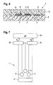
- the electrode system shown in Figure 3 is shown in a cross section, wherein the section line through the measuring electrodes 2, 3 and 7 extends.
- the electrodes 2, 3, 4, 5 and 7 are arranged on a common carrier 8, which preferably consists of plastic, for example of polyimide, and contacted by conductor tracks 6, via which the electrode system 1 can be connected to an evaluation unit (not shown) , In operation, the evaluation unit adjusts the potential of the measuring electrodes 2, 3, 7 to a predetermined value of, for example, 350 mV with respect to the reference electrode 5.
- the measuring electrodes for example by deposits of proteins after implantation with respect to the ground potential of the counter electrode 4 drift defined conditions for a precise evaluation of the measuring currents can be created in this way, since it can be assumed that the measuring electrodes 2, 3, 7 in the same way as the reference electrode 5 are subject to drift effects.
- the measuring electrodes 2, 3, 7 each have an area of 0.1 mm 2 to 0.5 mm 2 and, like the tracks 6, are made of gold.
- the measuring electrodes 2, 3, 7 are each covered with an enzyme layer 9, which contains an enzyme which generates charge carriers by catalytic conversion of the analyte, which are detected for the measuring signal.
- the charge carriers may be formed either directly or by reacting an intermediate formed by the enzyme first will be generated.
- An example of such an intermediate is hydrogen peroxide.
- the enzyme layers 9 are formed as carbon layers, which immobilize the enzyme glucose oxidase.
- the enzyme layers have a thickness of 3 .mu.m to 10 .mu.m, preferably 5 .mu.m.
- the different measuring sensitivities of the measuring electrodes 2, 3, 7 are preferably produced by the fact that at least one of the measuring electrodes 2, 3, 7 has a covering layer 11 which opposes the analyte with a diffusion resistance, whereby a difference between the measuring sensitivities of the measuring electrodes 2 is achieved by adapting the diffusion resistance , 3 and 7 is realized. Since the diffusion resistance of a cover layer 11 is the greater, the thicker the covering layer 11 in question, it is easiest to realize different diffusion resistances by cover layers 11 of different thicknesses.
- a 30 micron thick cover membrane of a weakly swelling polymer, such as polyurethane and on the second measuring electrode 3, a only 10 microns thick cover membrane of the same material can be applied. Due to different diffusion resistances of the outer layers of the measuring electrodes 2, 3 reach different time per unit of glucose molecules, the enzyme layers of the measuring electrodes 2, 3. From the stored enzyme in the enzyme glucose oxidase glucose molecules are degraded, so that charge carriers are free, which at the measuring electrodes 2, 3 are detected and form in this way the measuring currents I1 and I2. Different diffusion resistances can be realized in the simplest case by a different thickness of the cover layers of the measuring electrodes 2, 3.
- cover layer 11 of the measuring electrode 7 for high concentrations of silicone, which is relatively impermeable to glucose molecules used for the cover layer 11 of the measuring electrode 3 for medium concentrations of polyurethane, which is relatively transparent to glucose molecules and for the measuring electrode 2 to a Cover layer can be omitted.
- low-swelling polymers such as, for example, polyurethane
- the thickness of the cover membrane is preferably less than 50 .mu.m, more preferably 10 .mu.m to 30 .mu.m.
- the enzyme layers of the measuring electrodes 2, 3. Due to the different diffusion resistances of the cover layers 11 of the measuring electrodes 2, 3 reach different units of glucose molecules per unit time, the enzyme layers of the measuring electrodes 2, 3. From the stored enzyme in the enzyme glucose oxidase, the glucose molecules are degraded, so that charge carriers are released to the Measuring electrodes 2, 3 are detected and form in this way different measuring currents.
- Another possibility for realizing different measuring sensitivities of the first and second measuring electrodes 2, 3 is to use different enzyme layers 9.
- the amount of enzyme in the enzyme layer 9 can be selected to be twice as large as for the enzyme layer 9 of the second measuring electrode 3.
- a dialysis membrane 12 which preferably extends over the entire surface of the electrode system 1.
- a dialysis membrane 12 is understood as meaning a membrane which is impermeable to molecules above a maximum size.
- the dialysis membrane 12 is prefabricated in a separate manufacturing process and applied as a complete, existing structure in the manufacture of the electrode system 1. This maximum size of the dialysis membrane is selected for the illustrated electrode system 1 so that analyte molecules can pass through the dialysis membrane 12, but larger molecules are prevented.
- the dialysis membrane 12 is formed as a porous layer of a suitable plastic, in particular polyarylethersulfone.
- the effective surface of the measuring electrodes 2, 3, 7 can be increased and thus improve the signal-to-noise ratio. In principle, however, it is possible to dispense with a dialysis membrane if all measuring electrodes are provided with a covering layer 11.
- the individual measuring electrodes 2, 3, 7 are therefore preferably less than 1.5 mm, preferably less than 1 mm, particularly preferably less than 700 ⁇ m apart. If several measuring electrodes are used, care must therefore be taken that no large distances occur between the measuring electrodes furthest apart from each other.
- homogeneous analyte concentrations can be achieved, for example, by means of a sufficiently thick dialysis membrane. Therefore, the dialysis membrane preferably has a thickness from 50 microns to 500 microns, more preferably 100 microns to 300 microns.
- Another way to homogenize the analyte concentrations in the area of the electrode system 1 is not to arrange the dialysis membrane 12 directly on the measuring electrodes 2, 3, 7, but to arrange the measuring electrodes 2, 3, 7 in a small chamber which is closed by the dialysis membrane is.
- a chamber can be realized, for example, in that the measuring electrodes 2, 3, 7 are arranged in a suitable depression of the carrier 8 and the depression is covered by the dialysis membrane 12.
- the height of such a chamber, d. H. the distance from the surface of the measuring electrodes 2, 3, 7 (or their cover layer 11) to the underside of the dialysis membrane 12 is preferably less than 400 .mu.m, more preferably less than 300 .mu.m.
- Such a chamber like a thick dialysis membrane has the advantage of serving as a reservoir for the analyte, so that a temporary local blockade of the dialysis membrane 12 can be compensated.
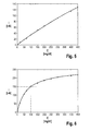
- FIG. 5 shows in detail the characteristic curve 20 already explained in connection with FIG. 1, which represents the functional dependence of the current I representing the measuring signal of the first measuring electrode 2 on the analyte concentration C.
- the measurement accuracy in determining high analyte concentrations is limited by saturation effects.
- glucose concentrations of more than 450 mg / dl practically do not occur, so that the course of the characteristic curve shown in FIG. 5 above 450 mg / dl is irrelevant.
- the sensitivity of the measuring electrode can be characterized by a single sensitivity parameter, which determines the derivative of the characteristic curve after the concentration, ie. H. the slope is. In practice, a perfectly linear relationship can not usually be realized, so that additional sensitivity parameters are needed to describe the course of the characteristic curve.
- the sensitivity of the first measuring electrode 2 at 450 mg / dl should be at least 80% of the sensitivity at 100 mg / dl, as is the case with the characteristic curve shown in FIG. Furthermore, the sensitivity at 100 mg / dl should be at least 0.1 nA / mg / dl, so that concentrations above 100 mg / dl can be detected with a sufficiently high signal-to-noise ratio. For concentrations below about 100 mg / dl, the characteristic curve shown in FIG. 5 leads to an increasingly unfavorable signal-to-noise ratio, so that the measurement accuracy for low concentrations is insufficient.
- a second measuring electrode For measuring analyte concentrations below 80 mg / dl, therefore, a second measuring electrode is used, which has a much higher sensitivity in this low concentration range.
- An example of the characteristic curve of a suitable measuring electrode is shown in FIG. 6 shown.
- the highest possible measuring sensitivity at low concentrations means the steepest possible characteristic curve in the corresponding concentration range. Since the measurement currents achievable with implanted electrodes are limited, high measurement sensitivity at low concentrations is associated with saturation at higher concentrations. This is shown in FIG. 6 by a marked flattening of the characteristic at concentrations of more than 200 mg / dl. For high concentrations, therefore, results in a very unfavorable signal to noise ratio, which, however, faces a very favorable signal to noise ratio at low concentrations.
- the measuring sensitivities of the first measuring electrode and the second measuring electrode differ at a reference concentration, for example a glucose concentration of 100 mg / dl, by at least a factor of 2, preferably at least a factor of 3.
- the reference concentration is preferably a concentration from the first or the second concentration range selected, for example, the arithmetic mean of the upper limit and the lower limit of one of the concentration ranges.
- Meßsensitterrorism is the derivative of the intensity of the measured signal after the concentration, d. H. to understand the slope of the characteristic at that concentration.
- the sensitivity of the second measuring electrode between 10 mg / dl and 100 mg / dl should be at least 1 nA / mg / dl. In this way, at a critical glucose concentration of 50 mg / dl currents of at least 50 nA, so that a signal-to-noise ratio of 5 or better can be achieved.
- FIG. 7 shows a schematic representation of a device according to the invention for measuring an analyte concentration with an electrode system 1 according to the invention.
- the electrode system 1 described above is connected to an evaluation unit 23 in the form of a microprocessor, in which at least one first sensitivity parameter characterizing the measuring sensitivity of the first measuring electrode 2 and at least one second sensitivity parameter characterizing the measuring sensitivity of the second measuring electrode 3 are stored , By evaluating at least one measuring signal of one of the measuring electrodes 2, 3, the evaluation unit 23 determines in which concentration range the analyte concentration lies in the vicinity of the electrode system.
- the analyte concentration is determined by evaluating the measuring signal of the first measuring electrode 2. If the analyte concentration is in the concentration range for which the measuring sensitivity of the second measuring electrode 3 is optimized, the analyte concentration is determined by evaluating the measuring signal of the second measuring electrode.
- analyte concentrations in an overlapping area can also be determined by evaluating the measuring signals of two measuring electrodes 2, 3.
- the first measuring electrode 2 is connected to a first potentiostat 21 and the second measuring electrode 3 to a second potentiostat 22.
- the potentiostats 21, 22 are each controlled by the microprocessor forming the control and evaluation unit 23.
- a potentiostat is an electronic control loop, with which the voltage applied to the respective measuring electrode 2, 3 potential is regulated with respect to a reference electrode 5 to a desired value.
- the reference point is represented by the reference electrode 5 whose potential is defined in the electrochemical series of voltages. By the reference electrode 5 itself preferably no current flows.
- the maximum measuring current is very limited because the charge carriers required for the measuring current are generated by enzymatic degradation of the analyte. Therefore, the influence of the measuring current and the enzyme used threatens to impoverish the analyte concentration in the environment of the electrode system 1 that is relevant for the measurement, in particular if the bodily tissue surrounding the measuring electrodes 2, 3 is only relatively weakly traversed by body fluid, or the transport of analyte molecules in the environment of the measuring electrodes 2, 3 is inhibited for other reasons, for example by a blockage.
- the amount of analyte that is typically consumed by a measuring electrode in the continuous measuring operation per minute, is in the picomole range, so it is relatively small.
- characteristic fall times can be determined for the measuring currents of the measuring electrodes 2, 3, wherein a self-adjusting equilibrium state can be taken into account numerically. If different characteristic fall times are detected by the evaluation unit 23 within a time period relevant to the depletion for the measuring electrodes 2, 3, an alarm signal can indicate the unreliability of the calculated glucose concentration.
- the detected depletion does not exceed a critical threshold value, it is possible to reduce the analyte concentration caused by the measurement current numerically in the evaluation of the measuring currents to determine the real analyte concentration in the body of the patient to compensate.
- the charge kinetics of the charge carriers with respect to the analyte can be detected by a simple model.
- the decay times determined by the evaluation unit 23 on the basis of the current measurements can be compared with theoretical values of the model and provide the basis for a numerical compensation of the local analyte concentration determined from the measured values.
- the evaluation unit 23 thus carries out a treatment process during the evaluation of the measurement signals.
- correction data which concern a local decrease in the analyte concentration caused by a measurement current are taken into account, wherein the measurement voltages applied to the measurement electrodes 2, 3 are switched on and off separately to obtain the correction data and the time course of the measurement currents is evaluated. in particular by determining characteristic decay times of the measuring currents. In the simplest case, these correction data may be the characteristic fall times themselves.
- the microprocessor 23 forms both the evaluation unit for evaluating the measuring signals and the control unit with which the measuring voltages applied to the measuring electrodes 2, 3 can be switched on and off separately.
- the evaluation unit 23 is designed in such a way that a local decrease in the analyte concentration caused by a measuring current after switching on the measuring voltage for at least one of the measuring electrodes 2, 3 is detected and in the evaluation for determining the analyte concentration in the analyzer human or animal body is taken into account. This consideration can be done in such a way that is indicated by a signal that a determination of the analyte concentration is currently not possible. Another possibility is to quantitatively detect the local decrease of the analyte concentration and to compensate numerically for the calculation of the analyte concentration in the body of the patient.
- the evaluation and control unit 23 may for example also serve to control an artificial pancreas or be connected to a display device displayed with the determined analyte concentrations and / or a patient before particularly high or low analyte concentrations requiring countermeasures, by a suitable signal, for example acoustic signal, is warned. It is particularly favorable in this context if the data transmission to the display device is wireless, for example by an infrared interface or by means of ultrasound.
Abstract
Description
Die Erfindung betrifft ein implantierbares Elektrodensystem, eine Vorrichtung mit einem derartigem Elektrodensystem und ein entsprechendes Verfahren zum Messen einer Analytkonzentration in einem menschlichen oder tierischem Körper. Ein derartiges Elektrodensystem ist beispielsweise aus der
Implantierbare Elektrodensysteme ermöglichen Messungen von physiologisch bedeutsamen Analyten wie beispielsweise Laktat oder Glukose in dem Körper eines Patienten. Derartige Messungen in vivo haben gegenüber üblichen Vorgehensweisen, bei denen eine Probe einer Körperflüssigkeit entnommen und außerhalb des Körpers analysiert wird, eine Reihe wichtiger Vorteile, insbesondere die Möglichkeit einer automatischen und kontinuierlichen Erfassung von Meßwerten.Implantable electrode systems enable measurements of physiologically important analytes, such as lactate or glucose in a patient's body. Such measurements in vivo have a number of important advantages over conventional approaches to taking a sample of body fluid and analyzing it outside the body, in particular the possibility of automatically and continuously acquiring readings.
Bekannte Implantate haben jedoch den Nachteil, daß sich mit ihnen Analytkonzentrationen nur mit einer geringeren Genauigkeit und Zuverlässigkeit bestimmen lassen, als es mit einer herkömmlichen ex-vivo Analyse möglich ist.However, known implants have the disadvantage that can be determined with them analyte concentrations only with a lower accuracy and reliability than is possible with a conventional ex-vivo analysis.
Zur Erhöhung der Meßgenauigkeit wird in der
Trotz der auf diese Weise erzielten Verbesserungen ist es mit bekannten Elektrodensystemen nicht möglich, die Glukosekonzentration in dem Körper eines Diabetikers mit ausreichender Genauigkeit zu messen, um mit hinreichender Zuverlässigkeit vor sehr tiefen oder sehr hohen Glukosekonzentrationswerten zu warnen, die Gegenmaßnahmen des Patienten erfordern.Despite the improvements thus achieved, known electrode systems fail to measure the glucose concentration in the body of a diabetic patient with sufficient accuracy to warn with reasonable reliability of very low or very high glucose concentration levels requiring patient intervention.
Aufgabe der Erfindung ist es deshalb, einen Weg aufzuzeigen, wie Analytkonzentrationen mit größerer Genauigkeit in einem menschlichen oder tierischen Körper gemessen werden kann.The object of the invention is therefore to show a way how analyte concentrations can be measured with greater accuracy in a human or animal body.
Diese Aufgabe wird gelöst durch ein implantierbares Elektrodensystem zum Messen einer Analytkonzentration in einem menschlichen oder tierischen Körper, umfassend eine erste und eine zweite Meßelektrode zum Ermitteln von Meßsignalen, die jeweils eine Information über die zu messende Analytkonzentration enthalten, wobei die erste Meßelektrode eine erste Meßsensitivität hat, die an einen ersten Konzentrationsbereich des Analyten angepaßt ist, und die zweite Meßelektrode eine zweite Meßsensitivität hat, die von der ersten Meßsensitivität verschieden und an einen zweiten Konzentrationsbereich des Analyten angepaßt ist.This object is achieved by an implantable electrode system for measuring an analyte concentration in a human or animal body, comprising a first and a second measuring electrode for determining measurement signals, each containing information about the analyte concentration to be measured, wherein the first measuring electrode has a first Meßsensitivität , which is adapted to a first concentration range of the analyte, and the second measuring electrode has a second Meßsensitivität, which differs from the first Meßsensitivität and adapted to a second concentration range of the analyte.
Die Aufgabe wird ferner gelöst durch eine Vorrichtung zum Messen einer Analytkonzentration in einem menschlichen oder tierischen Körper, umfassend ein derartiges Elektrodensystem, eine an das Elektrodensystem angeschlossene Auswerteeinheit zum Auswerten von Meßsignalen der ersten und der zweiten Meßelektrode, und einen Speicher, in dem mindestens ein die Meßsensitivität der ersten Meßelektrode charakterisierender erster Sensitivitätsparameter und mindestens ein die Meßsensitivität der zweiten Meßelektrode charakterisierender zweiter Sensitivitätsparameter gespeichert sind, wobei die Auswerteeinheit derart ausgebildet ist, daß durch Auswertung mindestens eines Meßsignals einer der beiden Meßelektroden feststellbar ist, in welchem Konzentrationsbereich die Analytkonzentration liegt, und falls die Analytkonzentration in dem ersten Konzentrationsbereich liegt, das Meßsignal der ersten Meßelektrode mittels des ersten Sensitivitätsparameters zum Bestimmen der Analytkonzentration ausgewertet wird, und falls die Analytkonzentration in dem zweiten Konzentrationsbereich liegt, das Meßsignal der zweiten Meßelektrode mittels des zweiten Sensitivitätsparameters zum Bestimmen der Analytkonzentration ausgewertet wird.The object is further achieved by a device for measuring an analyte concentration in a human or animal body, comprising such an electrode system, an evaluation unit connected to the electrode system for evaluating measuring signals of the first and second measuring electrodes, and a memory in which at least one of the The measuring unit is designed such that by evaluating at least one measuring signal of one of the two measuring electrodes can be determined, in which concentration range the analyte concentration is, and if the analyte concentration is in the first concentration range, the measurement signal of the first measurement electrode is by means of the first sensitivity parameter for determining the analyte concentration is evaluated, and if the analyte concentration is in the second concentration range, the measurement signal of the second measuring electrode is evaluated by means of the second sensitivity parameter for determining the analyte concentration.
Bei einer derartigen Vorrichtung können die Konzentrationsbereiche der Meßelektroden überlappen. Es ist sogar möglich, daß der Konzentrationsbereich einer Meßelektrode als kleiner Teilbereich vollständig in dem wesentlich größeren Konzentrationsbereich einer anderen Meßelektrode enthalten ist. Es ist deshalb möglich, daß beispielsweise das Meßsignal der ersten Meßelektrode stets ausgewertet wird und das Meßsignal der zweiten Meßelektrode nur dann herangezogen wird, wenn die Auswertung des ersten Meßsignals ergibt, daß die Analytkonzentration in dem Konzentrationsbereich der zweiten Meßelektrode liegt.In such a device, the concentration ranges of the measuring electrodes may overlap. It is even possible that the concentration range of a measuring electrode is included as a small portion completely in the much larger concentration range of another measuring electrode. It is therefore possible that, for example, the measuring signal of the first measuring electrode is always evaluated and the measuring signal of the second measuring electrode is used only when the evaluation of the first measuring signal shows that the analyte concentration is in the concentration range of the second measuring electrode.
Die Aufgabe wird ferner gelöst durch ein Verfahren zum Messen einer Analytkonzentration in einem menschlichen oder tierischen Körper mittels eines implantierten Elektrodensystems, das eine erste Meßelektrode mit einer ersten Meßsensitivität und eine zweite Meßelektrode mit einer zweiten Meßsensitivität, die von der ersten Meßsensitivität verschieden ist, umfaßt, wobei in einem ersten Konzentrationsbereich liegende Analytkonzentrationen durch Auswertung eines Meßsignals der ersten Meßelektrode und in einem zweiten Konzentrationsbereich liegende Analytkonzentrationen durch Auswertung eines Meßsignals der zweiten Meßelektrode ermittelt werden.The object is further achieved by a method for measuring an analyte concentration in a human or animal body by means of an implanted electrode system comprising a first measuring electrode having a first measuring sensitivity and a second measuring electrode having a second measuring sensitivity different from the first measuring sensitivity; wherein analyte concentrations lying in a first concentration range are determined by evaluating a measuring signal of the first measuring electrode and analyte concentrations lying in a second concentration range by evaluating a measuring signal of the second measuring electrode.
Im Rahmen der Erfindung wurde erkannt, daß sich im menschlichen oder tierischen Körper stark schwankende Analytkonzentrationen nicht ohne Einschränkung der Meßgenauigkeit mit einer einzigen Meßelektrode bestimmen lassen. Je größer nämlich der Meßbereich einer Meßelektrode gewählt wird, desto geringer ist typischerweise die Meßsensitivität bei niedrigen Konzentrationen. Anstatt bei der Konzeption einer Meßelektrode einen optimalen Kompromiß zwischen einem möglichst großen Meßbereich und einer möglichst hohen Meßsensitivität anzustreben, wird erfindungsgemäß ein großer Meßbereich durch die Verwendung von mehreren Meßelektroden erzielt, die unterschiedliche Meßbereiche abdecken und entsprechend unterschiedliche Meßsensitivitäten haben. Indem die Meßsensitivität der ersten Meßelektrode für einen ersten Konzentrationsbereich optimiert ist und die Meßsensitivität der zweiten Meßelektrode für einen zweiten Konzentrationsbereich optimiert ist, kann ohne Beschränkung der Meßgenauigkeit ein größerer Meßbereich realisiert werden.Within the scope of the invention, it has been recognized that highly fluctuating analyte concentrations in the human or animal body can not be determined with a single measuring electrode without limiting the measuring accuracy. Namely, the larger the measuring range of a measuring electrode is chosen, the lower is typically the measuring sensitivity at low concentrations. Instead of aiming for an optimal compromise between the largest possible measuring range and the highest possible measuring sensitivity in the design of a measuring electrode, a large measuring range is achieved according to the invention by the use of a plurality of measuring electrodes covering different measuring ranges and correspondingly different measuring sensitivities. By optimizing the measuring sensitivity of the first measuring electrode for a first concentration range and optimizing the measuring sensitivity of the second measuring electrode for a second concentration range, a larger measuring range can be realized without limiting the measuring accuracy.
Unabhängig davon, ob die Analytkonzentration in der Umgebung der Meßelektroden in Bezug auf einen physiologischen Normal- oder Durchschnittswert relativ hoch oder niedrig ist, kann deshalb mit einem erfindungsgemäßen Elektrodensystem die Analytkonzentration stets mit einer Meßelektrode gemessen werden, die eine für den betreffenden Konzentrationsbereich günstige Meßsensitivität hat. Auf diese Weise kann für beliebig große Meßbereiche eine deutliche Verbesserung der Meßgenauigkeit erzielt werden.Regardless of whether the analyte concentration in the vicinity of the measuring electrodes is relatively high or low with respect to a physiological normal or average value, the analyte concentration can therefore always be measured with a measuring electrode having a measuring sensitivity which is favorable for the concentration range in question , In this way, a significant improvement in the measurement accuracy can be achieved for arbitrarily large ranges.
Da mit einem erfindungsgemäßen Elektrodensystem ein wesentlich verbesserte Meßgenauigkeit erreicht werden kann, ist eine statistische Auswertung von Meßsignalen verschiedener Meßelektrode, wie sie im Stand der Technik praktiziert wird, nicht erforderlich, so daß erfindungsgemäß mit einfacheren Mitteln eine höhere Meßgenauigkeit erreicht werden kann. Selbstverständlich ist jedoch möglich in einem Elektrodensystem mehrere erste Meßelektroden für einen oberen Konzentrationsbereich und mehrere zweite Meßelektroden für einen unteren Konzentrationsbereich einzusetzen, um die Störanfälligkeit des Systems zu senken oder durch eine statistische Auswertung die Meßgenauigkeit weiter zu verbessern.Since a substantially improved measuring accuracy can be achieved with an electrode system according to the invention, a statistical evaluation of measuring signals of different measuring electrodes, as practiced in the prior art, is not required, so that according to the invention a higher measuring accuracy can be achieved with simpler means. Of course, however, it is possible to use in an electrode system a plurality of first measuring electrodes for an upper concentration range and a plurality of second measuring electrodes for a lower concentration range in order to reduce the susceptibility of the system or to further improve the measurement accuracy by a statistical evaluation.
Falls in einem Elektrodensystem mehrere erste oder mehrere zweite Meßelektroden eingesetzt werden, erfordert eine statistische Auswertung zur Verbesserung der Meßgenauigkeit eine getrennte Ansteuerung der einzelnen Meßelektroden. Bei einem erfindungsgemäßen Elektrodensystem können mehrere gleiche Meßelektroden aber auch in Parallelschaltung mit einer gemeinsamen Ansteuerung angeordnet werden, so daß das Stromsignal erhöht und das Signal-Rauschverhältnis auch ohne eine statistische Auswertung verbessert werden kann. Dies ist insbesondere dann vorteilhaft, wenn die betreffenden Meßelektroden an der unteren Grenze des für sie vorgesehenen Meßbereichs messen, da das Signal-Rauschverhältnis generell um so ungünstiger ist, je kleiner die zu messende Analytkonzentration ist.If a plurality of first or more second measuring electrodes are used in an electrode system, a statistical evaluation to improve the measuring accuracy requires a separate control of the individual measuring electrodes. In an electrode system according to the invention, a plurality of identical measuring electrodes can also be arranged in parallel connection with a common control, so that the current signal can be increased and the signal-to-noise ratio can be improved even without a statistical evaluation. This is particularly advantageous if Measure the relevant measuring electrodes at the lower limit of the measuring range intended for them, since the smaller the analyte concentration to be measured, the less favorable is the signal-to-noise ratio in general.
Falls aus Gründen des einfachen Aufbaus darauf verzichtet wird, mehrere gleiche Meßelektroden zu verwenden, wird bevorzugt die Fläche der Meßelektrode mit der geringeren Meßsensitivität größer, bevorzugt mindestens 50% größer, als die Fläche der Meßelektrode mit der (nächst) höheren Meßsensitivität gewählt. Auf diese Weise kann auch bei einer geringeren Meßsensitivität ein erhöhtes Stromsignal erhalten und somit das Signal-Rauschverhältnis verbessert werden.If it is omitted for reasons of ease of construction to use several identical measuring electrodes, the surface of the measuring electrode with the lower Meßsensitivität is preferably greater, preferably at least 50% greater than the surface of the measuring electrode with the (next) higher Meßsensitivität selected. In this way, even with a lower Meßsensitivität receive an increased current signal and thus the signal-to-noise ratio can be improved.
Die Erfindung wird nachfolgend anhand von in den Figuren dargestellten Ausführungsbeispielen näher erläutert. Die darin dargestellten Besonderheiten können einzeln oder in Kombination verwendet werden, um bevorzugte Ausgestaltungen zu schaffen. Gleiche oder einander entsprechende Bauteile sind mit übereinstimmenden Bezugszeichen gekennzeichnet. Es zeigen:
- Fig. 1
- ein Ablaufschema für die Ermittlung einer Analytkonzentration mit einem erfindungsgemäßen Elektrodensystem;
- Fig. 2
- ein Ausführungsbeispiel eines erfindungsgemäßen Elektrodensystems;
- Fig. 3
- ein weiteres Ausführungsbeispiel eines erfindungsgemäßen Elektrodensystems;
- Fig. 4
- das in
Figur 3 dargestellte Elektrodensystem in einer Querschnittsdarstellung; - Fig. 5
- ein Beispiel einer Kennlinie einer ersten Meßelektrode eines erfindungsgemäßen Elektrodensystems;
- Fig. 6
- ein Beispiel einer Kennlinie einer zweiten Meßelektrode eines erfindungsgemäßen Elektrodensystems; und
- Fig. 7
- eine schematische Darstellung einer erfindungsgemäßen Vorrichtung zum Messen einer Analytkonzentration mit einem erfindungsgemäßen Elektrodensystem.
- Fig. 1
- a flow chart for the determination of an analyte concentration with an electrode system according to the invention;
- Fig. 2
- an embodiment of an electrode system according to the invention;
- Fig. 3
- a further embodiment of an electrode system according to the invention;
- Fig. 4
- the electrode system shown in Figure 3 in a cross-sectional view;
- Fig. 5
- an example of a characteristic of a first measuring electrode of an electrode system according to the invention;
- Fig. 6
- an example of a characteristic of a second measuring electrode of an electrode system according to the invention; and
- Fig. 7
- a schematic representation of a device according to the invention for measuring an analyte concentration with an electrode system according to the invention.
Glukose ist ein wichtiges Beispiel für einen Analyten, dessen Konzentration im Blut und in anderen Körperflüssigkeiten eines Patienten im Tagesverlauf starken Schwankungen zwischen 40 mg/dl und 450 mg/dl unterliegen kann. Im folgendem wird deshalb ohne Beschränkung der Allgemeinheit die Ermittlung von Analytkonzentrationen am Beispiel von Messungen der Glucosekonzentration in Blut oder interstitieller Flüssigkeit erläutert.Glucose is an important example of an analyte whose concentration in the blood and other body fluids of a patient may vary greatly between 40 mg / dl and 450 mg / dl throughout the day. In the following, therefore, the determination of analyte concentrations will be explained by the example of measurements of the glucose concentration in blood or interstitial fluid without restriction of generality.
In Figur 1 ist ein Ablaufschema für die Ermittlung der Glukosekonzentration mit einem implantierbaren Elektrodensystem dargestellt, das zwei galvanisch getrennte Meßelektroden mit unterschiedlicher Sensitivität umfaßt. Eine erste Meßelektrode hat eine erste Meßsensitivität, die für einen ersten Konzentrationsbereich des Analyten von 80 mg/dl bis 500 mg/dl optimiert ist. Eine zweite Meßelektrode hat eine zweite Meßsensitivität, die für einen zweiten Konzentrationsbereich des Analyten von 20 mg/dl bis 80 mg/dl optimiert ist. Der erste Konzentrationsbereich ist also von dem zweiten Konzentrationsbereich verschieden. Bevorzugt unterscheiden sich die Obergrenzen der Konzentrationsbereiche mindestens um einen Faktor zwei.FIG. 1 shows a flow chart for the determination of the glucose concentration with an implantable electrode system comprising two galvanically separated measuring electrodes with different sensitivity. A first measuring electrode has a first measuring sensitivity which is optimized for a first concentration range of the analyte from 80 mg / dl to 500 mg / dl. A second measuring electrode has a second measuring sensitivity which is optimized for a second concentration range of the analyte from 20 mg / dl to 80 mg / dl. The first concentration range is thus different from the second concentration range. Preferably, the upper limits of the concentration ranges differ by at least a factor of two.
Die Meßelektroden liefern jeweils ein Meßsignal in Form eines elektrischen Stroms, dessen Stärke von der Analytkonzentration in der Umgebung der Meßelektroden abhängt. Für jede Meßelektrode beschreibt eine Kennlinie, die durch ein Sensitivitätsparameter charakterisiert sein kann, den Zusammenhang zwischen dem Strom I als Meßsignal und der dazugehörenden Analytkonzentration C.The measuring electrodes each provide a measuring signal in the form of an electric current, the strength of which depends on the analyte concentration in the vicinity of the measuring electrodes. For each measuring electrode, a characteristic curve, which may be characterized by a sensitivity parameter, describes the relationship between the current I as the measuring signal and the associated analyte concentration C.
Zur Bestimmung der Analytkonzentration wird in einem ersten Arbeitsschritt 10 das Meßsignal der ersten Meßelektrode mittels einer Kennlinie 20 ausgewertet und ein Wert CF für die Analytkonzentration bestimmt. In einem anschließenden Schritt 30 wird geprüft, ob der anhand des Meßsignals der ersten Meßelektrode ermittelte Wert CF in dem Konzentrationsbereich liegt, für den die Meßsensitivität der ersten Meßelektrode optimiert ist. Bei dem dargestellten Ausführungsbeispiel ist die erste Meßelektrode für Analytkonzentrationen von mehr als 80 mg/dl optimiert. Wird festgestellt, daß der ermittelte Wert CF in dem ersten Konzentrationsbereich liegt, d. h. 80 mg/dl übersteigt, so wird der Wert CF als Ergebnis ausgegeben.To determine the analyte concentration, the measurement signal of the first measuring electrode is evaluated in a
Beträgt der anhand der ersten Meßelektrode ermittelte Konzentrationswert CF weniger als 80 mg/dl, wird anschließend das Meßsignal der zweiten Meßelektrode anhand der Kennlinie 40 der zweiten Meßelektrode ausgewertet.If the concentration value C F determined using the first measuring electrode is less than 80 mg / dl, then the measuring signal of the second measuring electrode is evaluated on the basis of the
Bevorzugt hat die Kennlinie 40 der zweiten Meßelektrode bei kleinen Konzentrationswerten einen möglichst steilen Anstieg, so daß sich für niedrige Konzentrationen ein möglichst hohes Signal-Rauschverhältnis ergibt. Da der maximal als Meßsignal mögliche Strom begrenzt ist, bewirken Sättigungseffekte bei höheren Konzentrationen einen konstanten oder nahezu konstanten Maximalstrom Ilim. Im Gegensatz dazu hat die Kennlinie 20 der ersten Meßelektrode einen möglichst linearen Verlauf, so daß sich auch hohe Analytkonzentrationen ohne den Einfluß von Sättigungseffekten zuverlässig bestimmen lassen. Während bei der ersten Kennlinie 20 eine Auswertung von kleinen Meßströmen I, die mit niedrigen Konzentrationen korrespondieren, durch ein ungünstiges Signal-Rauschverhältnis erschwert ist, lassen sich mit der zweiten Kennlinie 40 Meßströme I, die einen Schwellenwert Ilim übersteigen, wegen Sättigungseffekten nicht sinnvoll auswerten.The
In einem Arbeitsschritt 50 wird deshalb geprüft, ob der Meßstrom I der zweiten Meßelektrode kleiner als ein vorgegebener Schwellenwert Ilim ist. Falls dies der Fall ist, ist ein durch Auswertung des Meßsignals der zweiten Meßelektrode gewonnener Konzentrationswert CH zuverlässiger als der anhand der ersten Meßelektrode bestimmte Konzentrationswert CF, so daß der Konzentrationswert CH als Ergebnis ausgegeben wird. Falls jedoch der Meßstrom der zweiten Meßelektrode größer oder gleich dem Schwellenwert Ilim ist, ist der anhand der ersten Meßelektrode bestimmte Konzentrationswert CF zuverlässiger als der anhand der zweiten Meßelektrode bestimmte Konzentrationswert CH, so daß der Wert CF als Konzentrationswert ausgegeben wird.In a
Prinzipiell kann auf den Arbeitsschritt 50 verzichtet werden, wenn der in dem Arbeitsschritt 30 geprüfte Schwellenwert, der bei dem dargestellten Beispiel 80 mg/dl beträgt, geeignet gewählt wird. Nach der Implantation eines Elektrodensystems kann es jedoch zu Änderungen der Meßsensitivität der einzelnen Meßelektroden kommen, so daß der Sättigungsbereich der zweiten Meßelektrode schon bei kleineren Konzentrationen beginnt. In dem Arbeitsschritt 50 kann dies erkannt werden und gegebenenfalls der Konzentrationsbereich, in dem Analytkonzentrationen mit der ersten Meßelektrode bestimmt werden, etwas zu tieferen Analytkonzentrationen hin ausgedehnt werden. Möglich ist es auch, den Konzentrationsbereich für den die erste Meßelektrode optimiert ist, und den Konzentrationsbereich für den die zweite Meßelektrode optimiert ist, überlappend zu wählen und in einem Überlappungsbereich die Analytkonzentration mittels einer statistischen Auswertung aus einem Auswerteergebnis der ersten Meßelektrode und einem Auswertungsergebnis der zweiten Meßelektrode zu ermitteln. Beispielsweise kann der Überlappungsbereich von 70 mg/dl bis 100 mg/dl gewählt werden. Die statistischen Gewichte, mit denen die Ergebnisse der ersten und der zweiten Meßelektrode in dem Überlappungsbereich gewichtet werden, können unter Berücksichtigung des Signal-Rauschverhältnisses des jeweiligen Meßsignals gewählt werden.In principle, step 50 can be dispensed with if the threshold value tested in
In Figur 2 ist ein Ausführungsbeispiel eines Elektrodensystems 1 dargestellt, mit dem sich das beschriebene Verfahren durchführen läßt. Das Elektrodensystem 1 umfaßt eine erste Meßelektrode 2 und eine zweite Meßelektrode 3, die jeweils unterschiedliche Meßsensitivitäten haben. Den beiden Meßelektroden 2, 3 ist eine gemeinsame Gegenelektrode 4 zugeordnet, die im Betrieb auf Massepotential gelegt wird, so daß zwischen der erste Meßelektrode 2 und der Gegenelektrode 4 ein erster Meßstrom I1 und zwischen der zweiten Meßelektrode 3 und der Gegenelektrode 4 ein zweiter Meßstrom I2 fließt. Das Elektrodensystem 1 umfaßt ferner eine Referenzelektrode 5, die ein Bezugspotential für die Meßelektroden 2, 3 liefert. Das Bezugspotential wird bevorzugt durch die Redoxreaktion Silber/Silberchlorid definiert, wobei selbstverständlich auch andere Redoxreaktionen für die Referenzelektrode genutzt werden können.FIG. 2 shows an exemplary embodiment of an
Prinzipiell kann auf einem separate Referenzelektrode 5 verzichtet werden und die Gegenelektrode 4 zugleich als Referenzelektrode genutzt werden. Da durch die Gegenelektrode 4 jedoch die Meßströme I1 und I2 fließen, würde dann die das Referenzpotential definierende Redoxreaktion (beispielsweise Silber/Silberchlorid) mit der Zeit zum Erliegen kommen, so daß die Lebensdauer des Elektrodensystems begrenzt wäre. Mit einer separaten Referenzelektrode 5 kann das Referenzpotential stromlos zur Verfügung gestellt werden, so daß sich in dieser Hinsicht keine Beschränkung für die Lebensdauer des Elektrodensystems ergibt.In principle, it is possible to dispense with a
In Figur 3 ist ein weiteres Ausführungsbeispiel eines implantierbaren Elektrodensystems 1 dargestellt, das sich von dem in Figur 2 dargestellten Ausführungsbeispiel abgesehen von Form und Anordnung der einzelnen Elektroden dadurch unterscheidet, daß insgesamt drei Meßelektroden 2, 3, 7 vorhanden sind. Ähnlich wie bei dem in Figur 2 dargestellten Elektrodensystem 1 dient die zweite Meßelektrode 3 dazu, Glukosekonzentrationen unterhalb von 80 mg/dl zu messen. Während bei dem in Figur 2 dargestellten Ausführungsbeispiel die erste Meßelektrode 2 für den gesamten Konzentrationsbereich oberhalb von 80 mg/dl verwendet wird, ist bei dem in Figur 3 dargestellten Elektrodensystem 1 eine dritte Meßelektrode 7 für Konzentrationen von mehr als 300 mg/dl vorhanden.FIG. 3 shows a further exemplary embodiment of an
Insbesondere bei Verwendung von mehr als zwei Meßelektroden ist es günstig, die Meßsensitivitäten der einzelnen Meßelektroden so zu wählen, daß sich überlappende Meßbereiche ergeben. Überlappt beispielsweise der erste Konzentrationsbereich, für den die Meßsensitivität der ersten Meßelektrode 2 optimiert ist, mit dem zweiten Konzentrationsbereich, für den die zweite Meßelektrode 3 optimiert ist, sind in dem Überlappungsbereich Plausibilitätsprüfungen möglich. Ferner können Analytkonzentrationen in dem oder den Überlappungsbereichen mittels einer statistischen Auswertung aus Auswertungsergebnissen von verschiedenen Meßelektroden ermittelt werden.In particular, when using more than two measuring electrodes, it is favorable to choose the measuring sensitivities of the individual measuring electrodes so that overlapping measuring ranges result. For example, overlaps the first concentration range, for which the measuring sensitivity of the
In Figur 4 ist das in Figur 3 dargestellte Elektrodensystem in einem Querschnitt dargestellt, wobei die Schnittlinie durch die Meßelektroden 2, 3 und 7 verläuft. Die Elektroden 2, 3, 4, 5 und 7 sind auf einem gemeinsamen Träger 8, der bevorzugt aus Kunststoff, beispielsweise aus Polyimid besteht, angeordnet und durch Leiterbahnen 6 kontaktiert, über die das Elektrodensystem 1 an eine Auswerteeinheit (nicht dargestellt) angeschlossen werden kann. Im Betrieb stellt die Auswerteeinheit das Potential der Meßelektroden 2, 3, 7 auf einen vorgegebenen Wert von beispielsweise 350 mV gegenüber der Referenzelektrode 5 ein. Obwohl die Meßelektroden, beispielsweise durch Anlagerungen von Proteinen nach Implantation gegenüber dem Massepotential der Gegenelektrode 4 driften, können auf diese Art und Weise definierte Verhältnisse für eine präzise Auswertung der Meßströme geschaffen werden, da davon ausgegangen werden kann, daß die Meßelektroden 2, 3, 7 in gleicher Weise wie die Referenzelektrode 5 Drifteffekten unterliegen.In Figure 4, the electrode system shown in Figure 3 is shown in a cross section, wherein the section line through the measuring
Die Meßelektroden 2, 3, 7 haben jeweils eine Fläche von 0,1 mm2 bis 0,5 mm2 und bestehen ebenso wie die Leiterbahnen 6 aus Gold. Die Meßelektroden 2, 3, 7 sind jeweils mit einer Enzymschicht 9 belegt, die ein Enzym enthält, das durch katalytische Umwandlung des Analyten Ladungsträger erzeugt, die für das Meßsignal erfaßt werden. Die Ladungsträger können entweder direkt oder durch Umsetzung eines Zwischenprodukts, das von dem Enzym zunächst gebildet wird, erzeugt werden. Ein Beispiel für ein derartiges Zwischenprodukt ist Wasserstoffperoxid. Bei dem dargestellten Ausführungsbeispiel sind die Enzymschichten 9 als Karbonschichten ausgebildet, die das Enzym Glukoseoxidase immobilisieren. Die Enzymschichten haben eine Dicke von 3 µm bis 10 µm, bevorzugt 5 µm.The measuring
Die unterschiedlichen Meßsensitivitäten der Meßelektroden 2, 3, 7 werden bevorzugt dadurch erzeugt, daß mindestens eine der Meßelektroden 2, 3, 7 eine Deckschicht 11 aufweist, die dem Analyten einen Diffusionswiderstand entgegensetzt, wobei durch Anpassung des Diffusionswiderstandes ein Unterschied zwischen den Meßsensitivitäten der Meßelektroden 2, 3 und 7 realisiert ist. Da der Diffusionswiderstand einer Deckschicht 11 um so größer ist, je dicker die betreffende Deckschicht 11 ist, lassen sich unterschiedliche Diffusionswiderstände am einfachsten durch unterschiedlich dicke Deckschichten 11 realisieren.The different measuring sensitivities of the measuring
Beispielsweise kann hierfür auf der ersten Meßelektrode 2 eine 30 µm dicke Deckmembran aus einem schwachquellenden Polymer, beispielsweise Polyurethan und auf der zweiten Meßelektrode 3 eine nur 10 µm starke Deckmembran aus dem selben Material aufgebracht werden. Bedingt durch unterschiedliche Diffusionswiderstände der Deckschichten der Meßelektroden 2, 3 erreichen pro Zeiteinheit unterschiedlich viele Glukosemoleküle, die Enzymschichten der Meßelektroden 2, 3. Von dem in der Enzymschicht gespeichertem Enzym Glukoseoxidase werden Glukosemoleküle abgebaut, so daß Ladungsträger frei werden, die an den Meßelektroden 2, 3 erfaßt werden und auf diese Weise die Meßströme I1 und I2 bilden. Unterschiedliche Diffusionswiderstände können im einfachsten Fall durch eine unterschiedliche Dicke der Deckschichten der Meßelektroden 2, 3 realisiert werden.For example, for this purpose, on the
Eine weitere Möglichkeit besteht darin, die Mikrostruktur der Deckschichten, beispielsweise deren Porosität, unterschiedlich zu gestalten oder die Deckschichten aus unterschiedlichen Materialien herzustellen. Beispielsweise kann für die Deckschicht 11 der Meßelektrode 7 für hohe Konzentrationen Silikon verwendet werden, das für Glukosemoleküle relativ undurchlässig ist, für die Deckschicht 11 der Meßelektrode 3 für mittlere Konzentrationen Polyurethan verwendet werden, das für Glukosemoleküle relativ durchlässig ist und für die Meßelektrode 2 auf eine Deckschicht verzichtet werden.Another possibility is to differentiate the microstructure of the cover layers, for example their porosity, or to produce the cover layers from different materials. For example, can be used for the
Für die Deckschicht 11 sind schwachquellende Polymere, wie beispielsweise Polyurethan besonders günstig. Die Dicke der Deckmembran beträgt bevorzugt weniger als 50 µm, besonders bevorzugt 10 µm bis 30 µm.For the
Bedingt durch die unterschiedlichen Diffusionswiderstände der Deckschichten 11 der Meßelektroden 2, 3 erreichen pro Zeiteinheit unterschiedlich viele Glukosemoleküle, die Enzymschichten der Meßelektroden 2, 3. Von dem in der Enzymschicht gespeichertem Enzym Glukoseoxidase werden die Glukosemoleküle abgebaut, so daß Ladungsträger frei werden, die an den Meßelektroden 2, 3 erfaßt werden und auf diese Weise unterschiedliche Meßströme bilden.Due to the different diffusion resistances of the cover layers 11 of the measuring
Eine weitere Möglichkeit unterschiedliche Meßsensitivitäten der ersten und der zweiten Meßelektrode 2, 3 zu realisieren, besteht darin, unterschiedliche Enzymschichten 9 einzusetzen. Beispielsweise kann zur Erhöhung der Meßsensitivität der ersten Meßelektrode 2 die Enzymmenge in der Enzymschicht 9 doppelt so groß gewählt werden, wie für die Enzymschicht 9 der zweiten Meßelektrode 3.Another possibility for realizing different measuring sensitivities of the first and
Die Meßelektroden 2, 3, 7 sind ferner von einer Dialysemembran 12 bedeckt, die sich bevorzugt über die gesamte Oberfläche des Elektrodensystems 1 erstreckt. Unter einer Dialysemembran 12 wird in diesem Zusammenhang eine Membran verstanden, die für Moleküle oberhalb einer Maximalgröße undurchlässig ist. Die Dialysemembran 12 wird in einem separaten Herstellungsprozeß vorgefertigt und als vollständige, bestehende Struktur bei der Fertigung des Elektrodensystems 1 aufgebracht. Diese Maximalgröße der Dialysemembran wird für das dargestellte Elektrodensystem 1 so gewählt, daß Analytmoleküle durch die Dialysemembran 12 hindurch treten können, größere Moleküle jedoch abgehalten werden. Beim dem dargestellten Ausführungsbeispiel ist die Dialysemembran 12 als eine poröse Schicht aus einem geeignetem Kunststoff, insbesondere Polyarylethersulfon, ausgebildet. Durch eine Dialysemembran 12 läßt sich die effektive Oberfläche der Meßelektroden 2, 3, 7 vergrößern und folglich das Signal-Rauschverhältnis verbessern. Prinzipiell kann auf eine Dialysemembran jedoch verzichtet werden, sofern alle Meßelektroden mit einer Deckschicht 11 versehen sind.The measuring
Wichtig für ein zuverlässiges Funktionieren des beschriebenen Elektrodensystems 1 ist, daß sämtliche Meßelektroden 2, 3, 7 der selben Analytkonzentration ausgesetzt sind. Bevorzugt sind die einzelnen Meßelektroden 2, 3, 7 deshalb weniger als 1,5 mm, bevorzugt weniger als 1 mm, besonders bevorzugt weniger als 700 µm voneinander entfernt. Werden mehrere Meßelektroden verwendet, ist deshalb darauf zu achten, daß auch zwischen den am weitesten voneinander entfernten Meßelektroden keine zu großen Abstände auftreten. Im Bereich des Elektrodensystems 1 lassen sich homogene Analytkonzentrationen, beispielsweise durch eine ausreichend dicke Dialysemembran bewirken. Bevorzugt hat die Dialysemembran deshalb eine Dicke von 50 µm bis 500 µm, besonders bevorzugt 100 µm bis 300 µm.Important for a reliable functioning of the described
Eine weitere Möglichkeit, die Analytkonzentrationen im Bereich des Elektrodensystems 1 zu homogenisieren besteht darin, die Dialysemembran 12 nicht unmittelbar auf den Meßelektroden 2, 3, 7 anzuordnen, sondern die Meßelektroden 2, 3, 7 in einer kleinen Kammer anzuordnen, die von der Dialysemembran verschlossen ist. Eine derartige Kammer läßt sich beispielsweise dadurch verwirklichen, daß die Meßelektroden 2, 3, 7 in einer geeigneten Vertiefung des Trägers 8 angeordnet werden und die Vertiefung von der Dialysemembran 12 bedeckt wird. Die Höhe einer solchen Kammer, d. h. der Abstand von der Oberfläche der Meßelektroden 2, 3, 7 (bzw. deren Deckschicht 11) bis zu der Unterseite der Dialysemembran 12 beträgt bevorzugt weniger als 400 µm, besonders bevorzugt weniger als 300 µm.Another way to homogenize the analyte concentrations in the area of the
Eine derartige Kammer hat ebenso wie eine dicke Dialysemembran den Vorteil als Reservoir für den Analyten zu dienen, so daß eine vorübergehende lokale Blockade der Dialysemembran 12 ausgeglichen werden kann.Such a chamber, like a thick dialysis membrane has the advantage of serving as a reservoir for the analyte, so that a temporary local blockade of the
In Figur 5 ist die im Zusammenhang von Figur 1 bereits erläutere Kennlinie 20 im Detail dargestellt, welche die funktionale Abhängigkeit des das Meßsignal der ersten Meßelektrode 2 darstellenden Stroms I von der Analytkonzentration C darstellt. In der Praxis wird die Meßgenauigkeit bei der Bestimmung hoher Analytkonzentrationen durch Sättigungseffekte beschränkt. Um die Meßsensitivität der ersten Meßelektrode für hohe Analytkonzentrationen zu optimieren, ist es deshalb günstig, über den gesamten physiologisch relevanten Konzentrationsbereich einen möglichst linearen Verlauf der Kennlinie anzustreben.FIG. 5 shows in detail the
Im menschlichen Körper kommen Glukosekonzentrationen von mehr als 450 mg/dl praktisch nicht vor, so daß der Verlauf der in Figur 5 dargestellten Kennlinie oberhalb von 450 mg/dl ohne Belang ist. Ist der Zusammenhang zwischen Strom I und Konzentration C linear, so läßt sich die Sensitivität der Meßelektrode durch einen einzigen Sensitivitätsparameter charakterisieren, der die Ableitung der Kennlinie nach der Konzentration, d. h. die Steigung ist. In der Praxis läßt sich ein perfekt linearer Zusammenhang meist nicht realisieren, so daß zusätzliche Sensitivitätsparameter benötigt werden, um den Verlauf der Kennlinie zu beschreiben.In the human body, glucose concentrations of more than 450 mg / dl practically do not occur, so that the course of the characteristic curve shown in FIG. 5 above 450 mg / dl is irrelevant. If the relationship between current I and concentration C is linear, then the sensitivity of the measuring electrode can be characterized by a single sensitivity parameter, which determines the derivative of the characteristic curve after the concentration, ie. H. the slope is. In practice, a perfectly linear relationship can not usually be realized, so that additional sensitivity parameters are needed to describe the course of the characteristic curve.
Damit der Einfluß von Sättigungseffekten möglichst vernachlässigbar ist, sollte die Sensitivität der ersten Meßelektrode 2 bei 450 mg/dl mindestens 80 % der Sensitivität bei 100 mg/dl betragen, wie dies bei in Figur 5 dargestellten Kennlinie der Fall ist. Des weiteren sollte die Sensitivität bei 100 mg/dl mindestens 0,1 nA/mg/dl betragen, so daß Konzentrationen oberhalb von 100 mg/dl mit einem ausreichend hohen Signal-Rauschverhältnis erfaßt werden können. Für Konzentrationen unterhalb von etwa 100 mg/dl führt die in Figur 5 dargestellte Kennlinie zu einem zunehmend ungünstigen Signal-Rauschverhältnis, so daß die Meßgenauigkeit für niedrige Konzentrationen unzureichend ist.So that the influence of saturation effects is as negligible as possible, the sensitivity of the
Zur Messung von Analytkonzentrationen unterhalb von 80 mg/dl wird deshalb eine zweite Meßelektrode verwendet, die im diesem niedrigen Konzentrationsbereich eine wesentlich höhere Sensitivität hat. Ein Beispiel der Kennlinie einer geeigneten Meßelektrode ist in Figur 6 dargestellt. Eine möglichst hohe Meßsensitivität bei niedrigen Konzentrationen bedeutet eine möglichst steile Kennlinie in dem entsprechenden Konzentrationsbereich. Da die mit implantierten Elektroden erzielbaren Meßströme begrenzt sind, ist eine hohe Meßsensitivität bei niedrigen Konzentrationen mit einer Sättigung bei höheren Konzentrationen verbunden. Dies zeigt sich in Figur 6 an einem deutlichen Abflachen der Kennlinie bei Konzentrationen von mehr als 200 mg/dl. Für hohe Konzentrationen ergibt sich deshalb ein sehr ungünstiges Signalrauschverhältnis, dem jedoch ein sehr günstiges Signalrauschverhältnis bei tiefen Konzentrationen gegenübersteht.For measuring analyte concentrations below 80 mg / dl, therefore, a second measuring electrode is used, which has a much higher sensitivity in this low concentration range. An example of the characteristic curve of a suitable measuring electrode is shown in FIG. 6 shown. The highest possible measuring sensitivity at low concentrations means the steepest possible characteristic curve in the corresponding concentration range. Since the measurement currents achievable with implanted electrodes are limited, high measurement sensitivity at low concentrations is associated with saturation at higher concentrations. This is shown in FIG. 6 by a marked flattening of the characteristic at concentrations of more than 200 mg / dl. For high concentrations, therefore, results in a very unfavorable signal to noise ratio, which, however, faces a very favorable signal to noise ratio at low concentrations.
Die Meßsensitivitäten der ersten Meßelektrode und der zweiten Meßelektrode unterscheiden sich bei einer Referenzkonzentration, beispielsweise einer Glucosekonzentration von 100 mg/dl, mindestens um einen Faktor 2, vorzugsweise mindestens um einen Faktor 3. Als Referenzkonzentration wird bevorzugt eine Konzentration aus dem ersten oder dem zweiten Konzentrationsbereich gewählt, beispielsweise das arithmetische Mittel aus der Obergrenze und der Untergrenze eines der Konzentrationsbereiche. Unter der Meßsensitivität ist dabei die Ableitung der Intensität des Meßsignals nach der Konzentration, d. h. die Steigung der Kennlinie bei der betreffenden Konzentration, zu verstehen.The measuring sensitivities of the first measuring electrode and the second measuring electrode differ at a reference concentration, for example a glucose concentration of 100 mg / dl, by at least a factor of 2, preferably at least a factor of 3. The reference concentration is preferably a concentration from the first or the second concentration range selected, for example, the arithmetic mean of the upper limit and the lower limit of one of the concentration ranges. Under the Meßsensitivität is the derivative of the intensity of the measured signal after the concentration, d. H. to understand the slope of the characteristic at that concentration.
Damit kritische Glukosekonzentrationen von 50 mg/dl mit der zweiten Meßelektrode zuverlässig erkannt werden können, sollte die Sensitivität der zweiten Meßelektrode zwischen 10 mg/dl und 100 mg/dl mindestens 1 nA/mg/dl betragen. Auf diese Weise ergeben sich bei einer kritischen Glukosekonzentration von 50 mg/dl Ströme von mindestens 50 nA, so daß ein Signal-Rauschverhältnis von 5 oder besser erreicht werden kann.So that critical glucose concentrations of 50 mg / dl can be reliably detected with the second measuring electrode, the sensitivity of the second measuring electrode between 10 mg / dl and 100 mg / dl should be at least 1 nA / mg / dl. In this way, at a critical glucose concentration of 50 mg / dl currents of at least 50 nA, so that a signal-to-noise ratio of 5 or better can be achieved.
In Figur 7 ist eine schematische Darstellung einer erfindungsgemäßen Vorrichtung zum Messen einer Analytkonzentration mit einem erfindungsgemäßen Elektrodensystem 1 dargestellt. Dabei ist das im vorhergehenden beschriebene Elektrodensystem 1 an eine Auswerteeinheit 23 in Form eines Mikroprozessors angeschlossen, die einen Speicher umfaßt, in dem mindestens ein die Meßsensitivität der ersten Meßelektrode 2 charakterisierender erster Sensitivitätsparameter und mindestens ein die Meßsensitivität der zweiten Meßelektrode 3 charakterisierender zweiter Sensitivitätsparameter gespeichert sind. Die Auswerteeinheit 23 stellt durch Auswertung mindestens eines Meßsignal einer der Meßelektroden 2, 3 fest, in welchem Konzentrationsbereich die Analytkonzentration in der Umgebung des Elektrodensystems liegt. Liegt die Analytkonzentration in dem Konzentrationsbereich, für den die Meßsensitivität der ersten Meßelektrode 2 optimiert ist, wird die Analytkonzentration durch Auswertung des Meßsignals der ersten Meßelektrode 2 ermittelt. Liegt die Analytkonzentration in dem Konzentrationsbereich, für den die Meßsensitivität der zweiten Meßelektrode 3 optimiert ist, wird die Analytkonzentration durch Auswertung des Meßsignals der zweiten Meßelektrode bestimmt.FIG. 7 shows a schematic representation of a device according to the invention for measuring an analyte concentration with an
Falls die Konzentrationsbereiche der einzelnen Meßelektroden 2, 3 überlappen, können Analytkonzentrationen in einem Überlappungsbereich auch durch Auswertung der Meßsignale von zwei Meßelektroden 2, 3 ermittelt werden.If the concentration ranges of the
Die erste Meßelektrode 2 ist an einen ersten Potentiostaten 21 und die zweite Meßelektrode 3 an einen zweiten Potentiostaten 22 angeschlossen. Die Potentiostaten 21, 22 werden jeweils von dem die Steuer- und Auswerteeinheit 23 bildenden Mikroprozessor gesteuert. Ein Potentiostat ist ein elektronischer Regelkreis, mit dem das an der betreffenden Meßelektrode 2, 3 anliegende Potential bezüglich einer Referenzelektrode 5 auf einen gewünschten Wert geregelt wird. Zwischen den Meßelektroden 2, 3, an denen die enzymatische Umsetzung des Analyten einschließlich Ladungsträgererzeugung bei entsprechender Potentialeinregelung erfolgt, und der Gegenelektrode 4 fließt der zu messende Strom. Der Referenzpunkt wird durch die Referenzelektrode 5 dargestellt, deren Potential in der elektrochemischen Spannungsreihe definiert ist. Durch die Referenzelektrode 5 selbst fließt bevorzugt kein Strom.The
Bei einem implantierten Elektrodensystem ist der maximale Meßstrom sehr begrenzt, da die für den Meßstrom erforderlichen Ladungsträger durch enzymatischen Abbau des Analyten erzeugt werden. Durch den Einfluß des Meßstroms und des verwendeten Enzyms droht deshalb die Analytkonzentration in der für die Messung relevanten Umgebung des Elektrodensystems 1 zu verarmen, insbesondere wenn das die Meßelektroden 2, 3 umgebende Körpergewebe nur relativ schwach von Körperflüssigkeit durchströmt wird, oder der Transport von Analytmolekülen in die Umgebung der Meßelektroden 2, 3 aus anderen Gründen, beispielsweise durch eine Blockade, gehemmt ist. Die Analytmenge, die von einer Meßelektrode im kontinuierlichen Meßbetrieb pro Minute typischerweise verbraucht wird, liegt im Pikomol-Bereich, ist also relativ klein. Dennoch kann durch die Verarmung der Analytkonzentration im Bereich der Meßelektroden 2, 3 eine Verfälschung der Messung auftreten. Im ungünstigsten Fall kann dieser Effekt zu einem physiologisch plausiblen Signalabfall führen, also eine Abnahme der Analytkonzentration im gesamten Körper des Patienten vortäuschen.In an implanted electrode system, the maximum measuring current is very limited because the charge carriers required for the measuring current are generated by enzymatic degradation of the analyte. Therefore, the influence of the measuring current and the enzyme used threatens to impoverish the analyte concentration in the environment of the
Mit der in Figur 7 dargestellten Vorrichtung läßt sich prüfen, ob ein mit dem Elektrodensystem 1 über einen bestimmten Zeitraum beobachteter Abfall der Glukosekonzentration eine natürliche Ursache hat und folglich im gesamten Körper des Patienten auftritt oder nur lokal in der Umgebung des Elektrodensystems auftritt. Ein nicht physiologischer Beitrag zu einem Signalabfall, der durch eine lokale Verarmung der Glukosekonzentration in der Umgebung der Meßelektroden 2, 3 verursacht wird, wird dadurch erkannt, daß an die Meßelektroden 2, 3 alternierend eine Meßspannung angelegt wird. Werden die Meßelektroden 2, 3 innerhalb eines zur Erkennung der Verarmung relevanten Zeitraums von mehreren Minuten getrennt an- und abgeschaltet, kann für jede Meßelektrode der Signalverlauf untersucht werden. Wird dabei für die Meßelektrode mit der höheren Meßsensitivität ein schnellerer Signalabfall festgestellt als für die Meßelektrode mit der niedrigeren Meßsensitivität, deutet dies auf eine Verarmung hin.With the device shown in Figure 7 can be checked whether a observed with the
Durch einen einfachen Algorithmus, beispielsweise eine lineare Ausgleichsrechnung oder eine nichtlineare Kurvenauswertung, können für die Meßströme der Meßelektroden 2, 3 jeweils charakteristische Abfallzeiten bestimmt werden, wobei ein sich einstellender Gleichgewichtszustand numerisch berücksichtigt werden kann. Werden dabei von der Auswerteeinheit 23 innerhalb eines für die Verarmung relevanten Zeitraums für die Meßelektroden 2, 3 unterschiedliche charakteristische Abfallzeiten festgestellt, kann durch ein Alarmsignal auf die Unzuverlässigkeit der errechneten Glukosekonzentration hingewiesen werden.By a simple algorithm, for example a linear compensation calculation or a non-linear curve evaluation, characteristic fall times can be determined for the measuring currents of the measuring
Sofern die festgestellte Verarmung einen kritischen Schwellenwert nicht übersteigt, besteht die Möglichkeit, die durch den Meßstrom bewirkte Abnahme der Analytkonzentration numerisch bei der Auswertung der Meßströme zur Bestimmung der realen Analytkonzentration in dem Körper des Patienten zu kompensieren. Beispielsweise kann die Verbrauchskinetik der Ladungsträger in bezug auf den Analyten durch ein einfaches Modell erfaßt werden. Die von der Auswerteeinheit 23 auf der Grundlage der aktuellen Messungen ermittelten Abfallzeiten können mit theoretischen Werten des Modells verglichen werden und die Grundlage für eine numerische Kompensation der aus den Meßwerten ermittelten lokalen Analytkonzentration liefern.If the detected depletion does not exceed a critical threshold value, it is possible to reduce the analyte concentration caused by the measurement current numerically in the evaluation of the measuring currents to determine the real analyte concentration in the body of the patient to compensate. For example, the charge kinetics of the charge carriers with respect to the analyte can be detected by a simple model. The decay times determined by the
Bei dem dargestellten Ausführungsbeispiel führt die Auswerteeinheit 23 also bei der Auswertung der Meßsignale ein Aufbereitungsverfahren durch. Bei diesem Verfahren werden Korrekturdaten, die eine durch einen Meßstrom bewirkte lokale Abnahme der Analytkonzentration betreffen, berücksichtigt, wobei zu der Gewinnung der Korrekturdaten die an den Meßelektroden 2, 3 anliegenden Meßspannungen separat an- und abgeschaltet werden und der zeitliche Verlauf der Meßströme ausgewertet wird, insbesondere indem charakteristische Abfallzeiten der Meßströme bestimmt werden. Im einfachsten Fall kann es sich bei diesen Korrekturdaten um die charakteristischen Abfallzeiten selbst handeln.In the illustrated embodiment, the
Bei dem in Figur 7 dargestellten Ausführungsbeispiel bildet der Mikroprozessor 23 sowohl die Auswerteeinheit zum Auswerten der Meßsignale als auch die Steuereinheit, mit der die jeweils an den Meßelektroden 2,3 anliegenden Meßspannungen separat an- und abschaltbar sind. Die Auswerteeinheit 23 ist derart ausgebildet, daß eine nach dem Einschalten der Meßspannung für mindestens eine der Meßelektroden 2, 3 durch einen Meßstrom bewirkte lokale Abnahme der Analytkonzentration erkannt und bei der Auswertung zur Bestimmung der Analytkonzentration in dem menschlichen oder tierischen Körper berücksichtigt wird. Diese Berücksichtigung kann in der Weise erfolgen, daß durch ein Signal angezeigt wird, daß eine Bestimmung der Analytkonzentration derzeit nicht möglich ist. Eine weitere Möglichkeit besteht darin, die lokale Abnahme der Analytkonzentration quantitativ zu erfassen und numerisch bei der Berechnung der Analytkonzentration in dem Körper des Patienten zu kompensieren.In the exemplary embodiment shown in FIG. 7, the
Die Auswerte- und Steuereinheit 23 kann beispielsweise auch zur Steuerung einer künstlichen Bauchspeicheldrüse dienen oder an eine Anzeigeeinrichtung angeschlossen sein, mit der ermittelte Analytkonzentrationen angezeigt oder/und ein Patient vor besonders hohen oder tiefen Analytkonzentrationen, die Gegenmaßnahmen erfordern, durch ein geeignetes Signal, beispielsweise ein akustisches Signal, gewarnt wird. Besonders günstig ist es in diesem Zusammenhang, wenn die Datenübertragung zu der Anzeigeeinrichtung drahtlos, beispielsweise durch eine Infrarotschnittstelle oder mittels Ultraschall, erfolgt.The evaluation and
Claims (13)
eine erste und eine zweite Meßelektrode (2, 3) zum Ermitteln von Meßsignalen, die jeweils eine Information über die zu messende Analytkonzentration enthalten, wobei
die erste Meßelektrode (2) eine erste Meßsensitivität hat, die an einen ersten Konzentrationsbereich des Analyten angepaßt ist, und
die zweite Meßelektrode (3) eine zweite Meßsensitivität hat, die von der ersten Meßsensitivität verschieden ist und an einen zweiten Konzentrationsbereich des Analyten angepaßt ist.An implantable electrode system for measuring an analyte concentration in a human or animal body, comprising
a first and a second measuring electrode (2, 3) for determining measurement signals, each containing information about the analyte concentration to be measured, wherein
the first measuring electrode (2) has a first Meßsensitivität, which is adapted to a first concentration range of the analyte, and
the second measuring electrode (3) has a second measuring sensitivity, which is different from the first measuring sensitivity and is adapted to a second concentration range of the analyte.
Priority Applications (1)
| Application Number | Priority Date | Filing Date | Title |
|---|---|---|---|
| EP06021578.7A EP1785086B1 (en) | 2005-11-12 | 2006-10-14 | Implantable electrode system and device for measuring the concentration of an analyte in a human or animal body |
Applications Claiming Priority (2)
| Application Number | Priority Date | Filing Date | Title |
|---|---|---|---|
| EP05024760A EP1785085A1 (en) | 2005-11-12 | 2005-11-12 | Implantable electrode system, method and device for measuring the concentration of an analyte in a human or animal body |
| EP06021578.7A EP1785086B1 (en) | 2005-11-12 | 2006-10-14 | Implantable electrode system and device for measuring the concentration of an analyte in a human or animal body |
Publications (3)
| Publication Number | Publication Date |
|---|---|
| EP1785086A2 true EP1785086A2 (en) | 2007-05-16 |
| EP1785086A3 EP1785086A3 (en) | 2009-01-28 |
| EP1785086B1 EP1785086B1 (en) | 2018-05-30 |
Family
ID=36095918
Family Applications (2)
| Application Number | Title | Priority Date | Filing Date |
|---|---|---|---|
| EP05024760A Withdrawn EP1785085A1 (en) | 2005-11-12 | 2005-11-12 | Implantable electrode system, method and device for measuring the concentration of an analyte in a human or animal body |
| EP06021578.7A Active EP1785086B1 (en) | 2005-11-12 | 2006-10-14 | Implantable electrode system and device for measuring the concentration of an analyte in a human or animal body |
Family Applications Before (1)
| Application Number | Title | Priority Date | Filing Date |
|---|---|---|---|
| EP05024760A Withdrawn EP1785085A1 (en) | 2005-11-12 | 2005-11-12 | Implantable electrode system, method and device for measuring the concentration of an analyte in a human or animal body |
Country Status (6)
| Country | Link |
|---|---|
| US (1) | US20070151868A1 (en) |
| EP (2) | EP1785085A1 (en) |
| JP (1) | JP2007130482A (en) |
| CN (1) | CN100475132C (en) |
| CA (1) | CA2567434A1 (en) |
| HK (1) | HK1104773A1 (en) |
Families Citing this family (25)
| Publication number | Priority date | Publication date | Assignee | Title |
|---|---|---|---|---|
| US20080119703A1 (en) | 2006-10-04 | 2008-05-22 | Mark Brister | Analyte sensor |
| US20190357827A1 (en) | 2003-08-01 | 2019-11-28 | Dexcom, Inc. | Analyte sensor |
| EP2256493B1 (en) | 2003-12-05 | 2014-02-26 | DexCom, Inc. | Calibration techniques for a continuous analyte sensor |
| US11633133B2 (en) | 2003-12-05 | 2023-04-25 | Dexcom, Inc. | Dual electrode system for a continuous analyte sensor |
| US8423114B2 (en) | 2006-10-04 | 2013-04-16 | Dexcom, Inc. | Dual electrode system for a continuous analyte sensor |
| US8364231B2 (en) | 2006-10-04 | 2013-01-29 | Dexcom, Inc. | Analyte sensor |
| AU2007303239A1 (en) | 2006-10-04 | 2008-04-10 | Dexcom, Inc. | Dual electrode system for a continuous analyte sensor |
| JP5164656B2 (en) * | 2008-04-25 | 2013-03-21 | 株式会社船井電機新応用技術研究所 | Sensor and biosensor |
| JP5378719B2 (en) * | 2008-07-08 | 2013-12-25 | 株式会社船井電機新応用技術研究所 | Sensor system |
| EP2163190A1 (en) * | 2008-09-11 | 2010-03-17 | Roche Diagnostics GmbH | Electrode system for measurement of an analyte concentration in-vivo |
| US20120077258A1 (en) * | 2009-02-17 | 2012-03-29 | Foertsch Stefan | Diagnostic device |
| US20110027458A1 (en) | 2009-07-02 | 2011-02-03 | Dexcom, Inc. | Continuous analyte sensors and methods of making same |
| DK3575796T3 (en) | 2011-04-15 | 2021-01-18 | Dexcom Inc | ADVANCED ANALYZE SENSOR CALIBRATION AND ERROR DETECTION |
| US10561351B2 (en) | 2011-07-26 | 2020-02-18 | Glysens Incorporated | Tissue implantable sensor with hermetically sealed housing |
| US10156543B2 (en) | 2012-06-08 | 2018-12-18 | Medtronic Minimed, Inc. | Application of electrochemical impedance spectroscopy in sensor systems, devices, and related methods |
| US10660550B2 (en) | 2015-12-29 | 2020-05-26 | Glysens Incorporated | Implantable sensor apparatus and methods |
| US10561353B2 (en) * | 2016-06-01 | 2020-02-18 | Glysens Incorporated | Biocompatible implantable sensor apparatus and methods |
| US9743871B2 (en) * | 2012-09-24 | 2017-08-29 | Dexcom, Inc. | Multiple electrode system for a continuous analyte sensor, and related methods |
| JP5350531B2 (en) * | 2012-12-18 | 2013-11-27 | 株式会社船井電機新応用技術研究所 | Sensor |
| US10638962B2 (en) | 2016-06-29 | 2020-05-05 | Glysens Incorporated | Bio-adaptable implantable sensor apparatus and methods |
| WO2018057695A1 (en) * | 2016-09-21 | 2018-03-29 | University Of Cincinnati | Accurate enzymatic sensing of sweat analytes |
| US10638979B2 (en) | 2017-07-10 | 2020-05-05 | Glysens Incorporated | Analyte sensor data evaluation and error reduction apparatus and methods |
| US11278668B2 (en) | 2017-12-22 | 2022-03-22 | Glysens Incorporated | Analyte sensor and medicant delivery data evaluation and error reduction apparatus and methods |
| US11255839B2 (en) | 2018-01-04 | 2022-02-22 | Glysens Incorporated | Apparatus and methods for analyte sensor mismatch correction |
| JP7316437B2 (en) | 2020-02-28 | 2023-07-27 | Phcホールディングス株式会社 | Sensor manufacturing method |
Citations (7)
| Publication number | Priority date | Publication date | Assignee | Title |
|---|---|---|---|---|
| US6175752B1 (en) | 1998-04-30 | 2001-01-16 | Therasense, Inc. | Analyte monitoring device and methods of use |
| JP2003190122A (en) | 2001-12-27 | 2003-07-08 | Nishitomo:Kk | Instrument for measuring biological information and sensor for measuring biological information |
| WO2004041082A1 (en) | 2002-11-01 | 2004-05-21 | Pelikan Technologies, Inc. | Method and apparatus for body fluid sampling |
| US20040111017A1 (en) | 1999-06-18 | 2004-06-10 | Therasense, Inc. | Mass transport limited in vivo analyte sensor |
| US20050051427A1 (en) | 2003-07-23 | 2005-03-10 | Brauker James H. | Rolled electrode array and its method for manufacture |
| WO2005032362A2 (en) | 2003-09-30 | 2005-04-14 | Roche Diagnostics Gmbh | Sensor with increaseed biocompatibility |
| US20050103625A1 (en) | 2001-07-27 | 2005-05-19 | Rathbun Rhodes | Sensor head for use with implantable devices |
Family Cites Families (9)
| Publication number | Priority date | Publication date | Assignee | Title |
|---|---|---|---|---|
| US4484987A (en) * | 1983-05-19 | 1984-11-27 | The Regents Of The University Of California | Method and membrane applicable to implantable sensor |
| US4655880A (en) * | 1983-08-01 | 1987-04-07 | Case Western Reserve University | Apparatus and method for sensing species, substances and substrates using oxidase |
| WO2002064027A2 (en) * | 2001-02-15 | 2002-08-22 | The Regents Of The University Of California | Membrane and electrode structure for implantable sensor |
| WO2003000127A2 (en) * | 2001-06-22 | 2003-01-03 | Cygnus, Inc. | Method for improving the performance of an analyte monitoring system |
| US9795334B2 (en) * | 2002-04-19 | 2017-10-24 | Sanofi-Aventis Deutschland Gmbh | Method and apparatus for penetrating tissue |
| US7964390B2 (en) * | 2002-10-11 | 2011-06-21 | Case Western Reserve University | Sensor system |
| US7248912B2 (en) * | 2002-10-31 | 2007-07-24 | The Regents Of The University Of California | Tissue implantable sensors for measurement of blood solutes |
| US8086323B2 (en) * | 2003-09-23 | 2011-12-27 | Medtronic Minimed, Inc. | Implantable multi-parameter sensing system and method |
| EP2256493B1 (en) * | 2003-12-05 | 2014-02-26 | DexCom, Inc. | Calibration techniques for a continuous analyte sensor |
-
2005
- 2005-11-12 EP EP05024760A patent/EP1785085A1/en not_active Withdrawn
-
2006
- 2006-10-14 EP EP06021578.7A patent/EP1785086B1/en active Active
- 2006-11-07 CA CA002567434A patent/CA2567434A1/en not_active Abandoned
- 2006-11-10 CN CNB2006101484619A patent/CN100475132C/en active Active
- 2006-11-10 JP JP2006305412A patent/JP2007130482A/en active Pending
- 2006-11-12 US US11/558,933 patent/US20070151868A1/en not_active Abandoned
-
2007
- 2007-09-13 HK HK07109972.6A patent/HK1104773A1/en not_active IP Right Cessation
Patent Citations (7)
| Publication number | Priority date | Publication date | Assignee | Title |
|---|---|---|---|---|
| US6175752B1 (en) | 1998-04-30 | 2001-01-16 | Therasense, Inc. | Analyte monitoring device and methods of use |
| US20040111017A1 (en) | 1999-06-18 | 2004-06-10 | Therasense, Inc. | Mass transport limited in vivo analyte sensor |
| US20050103625A1 (en) | 2001-07-27 | 2005-05-19 | Rathbun Rhodes | Sensor head for use with implantable devices |
| JP2003190122A (en) | 2001-12-27 | 2003-07-08 | Nishitomo:Kk | Instrument for measuring biological information and sensor for measuring biological information |
| WO2004041082A1 (en) | 2002-11-01 | 2004-05-21 | Pelikan Technologies, Inc. | Method and apparatus for body fluid sampling |
| US20050051427A1 (en) | 2003-07-23 | 2005-03-10 | Brauker James H. | Rolled electrode array and its method for manufacture |
| WO2005032362A2 (en) | 2003-09-30 | 2005-04-14 | Roche Diagnostics Gmbh | Sensor with increaseed biocompatibility |
Also Published As
| Publication number | Publication date |
|---|---|
| US20070151868A1 (en) | 2007-07-05 |
| CA2567434A1 (en) | 2007-05-12 |
| CN100475132C (en) | 2009-04-08 |
| HK1104773A1 (en) | 2008-01-25 |
| CN1961821A (en) | 2007-05-16 |
| JP2007130482A (en) | 2007-05-31 |
| EP1785085A1 (en) | 2007-05-16 |
| EP1785086B1 (en) | 2018-05-30 |
| EP1785086A3 (en) | 2009-01-28 |
Similar Documents
| Publication | Publication Date | Title |
|---|---|---|
| EP1785086B1 (en) | Implantable electrode system and device for measuring the concentration of an analyte in a human or animal body | |
| EP1733676B1 (en) | Sensor system, arrangement and method for monitoring a compound, in particular glucose in body tissue. | |
| DE60133653T2 (en) | APPARATUS FOR PREDICTING HYPOGLYECURE DROPS | |
| DE69910007T2 (en) | DEVICE FOR PREDICTING PHYSIOLOGICAL MEASUREMENTS | |
| DE60209498T2 (en) | MEMBRANE FOR USE WITH IMPLANTABLE DEVICES | |
| DE2817363C2 (en) | Method for determining the concentration of sugar and a suitable electrocatalytic sugar sensor | |
| Suarez-Perez et al. | Quantification of signal-to-noise ratio in cerebral cortex recordings using flexible MEAs with co-localized platinum black, carbon nanotubes, and gold electrodes | |
| DE10338280A1 (en) | Biosensor for monitoring analyte content with partial voltage, comprises chip generating time-dependent response current, power source, and microprocessor | |
| DE60114159T2 (en) | MEASUREMENT OF SUBSTANCES IN LIQUIDS | |
| EP0170998B1 (en) | Method for the electrochemical determination of oxygen concentration | |
| DE102006043718B4 (en) | Determination of hydrogen peroxide concentrations | |
| DE202004021824U1 (en) | Microprocessors and devices for monitoring physiological analytes | |
| EP2163190A1 (en) | Electrode system for measurement of an analyte concentration in-vivo | |
| Johnson et al. | Spatiotemporal pH dynamics following insertion of neural microelectrode arrays | |
| CH660922A5 (en) | IN VITRO METHOD AND IMPLANTABLE DEVICE FOR GLUCOSE CONCENTRATION DETECTION IN BIOLOGICAL FLUIDS. | |
| DE10392210T5 (en) | Method and device for monitoring an analytical concentration by means of an osmosis differential pressure measurement | |
| DE102011007918B4 (en) | Biosensor, monitor, program and method | |
| EP2438861A1 (en) | Medical sensor system for detecting at least one feature in at least one animal body and/or human body | |
| DE4221848C2 (en) | Method and arrangement for automatic in situ calibration of intracorporeal glucose measuring devices | |
| EP1259800B1 (en) | Enzymatic-electrochemical measuring device | |
| DE10119527A1 (en) | Method for the mobile or stationary acquisition of body function and metabolic data of a living body and device for carrying out the method | |
| DE4426694C2 (en) | Device for long-term determination of the content of at least one substance in body fluids | |
| EP1879494A2 (en) | Method and device for determining the glucose concentration in tissue liquid | |
| DE60220288T2 (en) | Determining the accuracy of a sample volume in biosensors | |
| EP0539814B1 (en) | Electrocatalytic glucose sensor |
Legal Events
| Date | Code | Title | Description |
|---|---|---|---|
| PUAI | Public reference made under article 153(3) epc to a published international application that has entered the european phase |
Free format text: ORIGINAL CODE: 0009012 |
|
| AK | Designated contracting states |
Kind code of ref document: A2 Designated state(s): AT BE BG CH CY CZ DE DK EE ES FI FR GB GR HU IE IS IT LI LT LU LV MC NL PL PT RO SE SI SK TR |
|
| AX | Request for extension of the european patent |
Extension state: AL BA HR MK YU |
|
| PUAL | Search report despatched |
Free format text: ORIGINAL CODE: 0009013 |
|
| AK | Designated contracting states |
Kind code of ref document: A3 Designated state(s): AT BE BG CH CY CZ DE DK EE ES FI FR GB GR HU IE IS IT LI LT LU LV MC NL PL PT RO SE SI SK TR |
|
| AX | Request for extension of the european patent |
Extension state: AL BA HR MK RS |
|
| 17P | Request for examination filed |
Effective date: 20090211 |
|
| 17Q | First examination report despatched |
Effective date: 20090309 |
|
| AKX | Designation fees paid |
Designated state(s): AT BE BG CH CY CZ DE DK EE ES FI FR GB GR HU IE IS IT LI LT LU LV MC NL PL PT RO SE SI SK TR |
|
| RAP1 | Party data changed (applicant data changed or rights of an application transferred) |
Owner name: F. HOFFMANN-LA ROCHE AG Owner name: ROCHE DIABETES CARE GMBH |
|
| GRAP | Despatch of communication of intention to grant a patent |
Free format text: ORIGINAL CODE: EPIDOSNIGR1 |
|
| INTG | Intention to grant announced |
Effective date: 20180104 |
|
| GRAS | Grant fee paid |
Free format text: ORIGINAL CODE: EPIDOSNIGR3 |
|
| GRAA | (expected) grant |
Free format text: ORIGINAL CODE: 0009210 |
|
| AK | Designated contracting states |
Kind code of ref document: B1 Designated state(s): AT BE BG CH CY CZ DE DK EE ES FI FR GB GR HU IE IS IT LI LT LU LV MC NL PL PT RO SE SI SK TR |
|
| REG | Reference to a national code |
Ref country code: GB Ref legal event code: FG4D Free format text: NOT ENGLISH |
|
| REG | Reference to a national code |
Ref country code: CH Ref legal event code: EP |
|
| REG | Reference to a national code |
Ref country code: AT Ref legal event code: REF Ref document number: 1002708 Country of ref document: AT Kind code of ref document: T Effective date: 20180615 |
|
| REG | Reference to a national code |
Ref country code: IE Ref legal event code: FG4D Free format text: LANGUAGE OF EP DOCUMENT: GERMAN |
|
| REG | Reference to a national code |
Ref country code: DE Ref legal event code: R096 Ref document number: 502006015910 Country of ref document: DE |
|
| REG | Reference to a national code |
Ref country code: FR Ref legal event code: PLFP Year of fee payment: 13 |
|
| REG | Reference to a national code |
Ref country code: NL Ref legal event code: MP Effective date: 20180530 |
|
| REG | Reference to a national code |
Ref country code: LT Ref legal event code: MG4D |
|
| PG25 | Lapsed in a contracting state [announced via postgrant information from national office to epo] |
Ref country code: SE Free format text: LAPSE BECAUSE OF FAILURE TO SUBMIT A TRANSLATION OF THE DESCRIPTION OR TO PAY THE FEE WITHIN THE PRESCRIBED TIME-LIMIT Effective date: 20180530 Ref country code: FI Free format text: LAPSE BECAUSE OF FAILURE TO SUBMIT A TRANSLATION OF THE DESCRIPTION OR TO PAY THE FEE WITHIN THE PRESCRIBED TIME-LIMIT Effective date: 20180530 Ref country code: BG Free format text: LAPSE BECAUSE OF FAILURE TO SUBMIT A TRANSLATION OF THE DESCRIPTION OR TO PAY THE FEE WITHIN THE PRESCRIBED TIME-LIMIT Effective date: 20180830 Ref country code: CY Free format text: LAPSE BECAUSE OF FAILURE TO SUBMIT A TRANSLATION OF THE DESCRIPTION OR TO PAY THE FEE WITHIN THE PRESCRIBED TIME-LIMIT Effective date: 20180530 Ref country code: ES Free format text: LAPSE BECAUSE OF FAILURE TO SUBMIT A TRANSLATION OF THE DESCRIPTION OR TO PAY THE FEE WITHIN THE PRESCRIBED TIME-LIMIT Effective date: 20180530 Ref country code: LT Free format text: LAPSE BECAUSE OF FAILURE TO SUBMIT A TRANSLATION OF THE DESCRIPTION OR TO PAY THE FEE WITHIN THE PRESCRIBED TIME-LIMIT Effective date: 20180530 |
|
| PG25 | Lapsed in a contracting state [announced via postgrant information from national office to epo] |
Ref country code: GR Free format text: LAPSE BECAUSE OF FAILURE TO SUBMIT A TRANSLATION OF THE DESCRIPTION OR TO PAY THE FEE WITHIN THE PRESCRIBED TIME-LIMIT Effective date: 20180831 Ref country code: LV Free format text: LAPSE BECAUSE OF FAILURE TO SUBMIT A TRANSLATION OF THE DESCRIPTION OR TO PAY THE FEE WITHIN THE PRESCRIBED TIME-LIMIT Effective date: 20180530 |
|
| PG25 | Lapsed in a contracting state [announced via postgrant information from national office to epo] |
Ref country code: NL Free format text: LAPSE BECAUSE OF FAILURE TO SUBMIT A TRANSLATION OF THE DESCRIPTION OR TO PAY THE FEE WITHIN THE PRESCRIBED TIME-LIMIT Effective date: 20180530 |
|
| PG25 | Lapsed in a contracting state [announced via postgrant information from national office to epo] |
Ref country code: RO Free format text: LAPSE BECAUSE OF FAILURE TO SUBMIT A TRANSLATION OF THE DESCRIPTION OR TO PAY THE FEE WITHIN THE PRESCRIBED TIME-LIMIT Effective date: 20180530 Ref country code: CZ Free format text: LAPSE BECAUSE OF FAILURE TO SUBMIT A TRANSLATION OF THE DESCRIPTION OR TO PAY THE FEE WITHIN THE PRESCRIBED TIME-LIMIT Effective date: 20180530 Ref country code: EE Free format text: LAPSE BECAUSE OF FAILURE TO SUBMIT A TRANSLATION OF THE DESCRIPTION OR TO PAY THE FEE WITHIN THE PRESCRIBED TIME-LIMIT Effective date: 20180530 Ref country code: PL Free format text: LAPSE BECAUSE OF FAILURE TO SUBMIT A TRANSLATION OF THE DESCRIPTION OR TO PAY THE FEE WITHIN THE PRESCRIBED TIME-LIMIT Effective date: 20180530 Ref country code: DK Free format text: LAPSE BECAUSE OF FAILURE TO SUBMIT A TRANSLATION OF THE DESCRIPTION OR TO PAY THE FEE WITHIN THE PRESCRIBED TIME-LIMIT Effective date: 20180530 Ref country code: SK Free format text: LAPSE BECAUSE OF FAILURE TO SUBMIT A TRANSLATION OF THE DESCRIPTION OR TO PAY THE FEE WITHIN THE PRESCRIBED TIME-LIMIT Effective date: 20180530 |
|
| REG | Reference to a national code |
Ref country code: DE Ref legal event code: R097 Ref document number: 502006015910 Country of ref document: DE |
|
| PLBE | No opposition filed within time limit |
Free format text: ORIGINAL CODE: 0009261 |
|
| STAA | Information on the status of an ep patent application or granted ep patent |
Free format text: STATUS: NO OPPOSITION FILED WITHIN TIME LIMIT |
|
| 26N | No opposition filed |
Effective date: 20190301 |
|
| PG25 | Lapsed in a contracting state [announced via postgrant information from national office to epo] |
Ref country code: SI Free format text: LAPSE BECAUSE OF FAILURE TO SUBMIT A TRANSLATION OF THE DESCRIPTION OR TO PAY THE FEE WITHIN THE PRESCRIBED TIME-LIMIT Effective date: 20180530 |
|
| REG | Reference to a national code |
Ref country code: BE Ref legal event code: MM Effective date: 20181031 |
|
| PG25 | Lapsed in a contracting state [announced via postgrant information from national office to epo] |
Ref country code: LU Free format text: LAPSE BECAUSE OF NON-PAYMENT OF DUE FEES Effective date: 20181014 Ref country code: MC Free format text: LAPSE BECAUSE OF FAILURE TO SUBMIT A TRANSLATION OF THE DESCRIPTION OR TO PAY THE FEE WITHIN THE PRESCRIBED TIME-LIMIT Effective date: 20180530 |
|
| REG | Reference to a national code |
Ref country code: IE Ref legal event code: MM4A |
|
| PG25 | Lapsed in a contracting state [announced via postgrant information from national office to epo] |
Ref country code: BE Free format text: LAPSE BECAUSE OF NON-PAYMENT OF DUE FEES Effective date: 20181031 |
|
| PG25 | Lapsed in a contracting state [announced via postgrant information from national office to epo] |
Ref country code: IE Free format text: LAPSE BECAUSE OF NON-PAYMENT OF DUE FEES Effective date: 20181014 |
|
| REG | Reference to a national code |
Ref country code: AT Ref legal event code: MM01 Ref document number: 1002708 Country of ref document: AT Kind code of ref document: T Effective date: 20181014 |
|
| PG25 | Lapsed in a contracting state [announced via postgrant information from national office to epo] |
Ref country code: AT Free format text: LAPSE BECAUSE OF NON-PAYMENT OF DUE FEES Effective date: 20181014 |
|
| PG25 | Lapsed in a contracting state [announced via postgrant information from national office to epo] |
Ref country code: TR Free format text: LAPSE BECAUSE OF FAILURE TO SUBMIT A TRANSLATION OF THE DESCRIPTION OR TO PAY THE FEE WITHIN THE PRESCRIBED TIME-LIMIT Effective date: 20180530 |
|
| PG25 | Lapsed in a contracting state [announced via postgrant information from national office to epo] |
Ref country code: PT Free format text: LAPSE BECAUSE OF FAILURE TO SUBMIT A TRANSLATION OF THE DESCRIPTION OR TO PAY THE FEE WITHIN THE PRESCRIBED TIME-LIMIT Effective date: 20180530 |
|
| PG25 | Lapsed in a contracting state [announced via postgrant information from national office to epo] |
Ref country code: HU Free format text: LAPSE BECAUSE OF FAILURE TO SUBMIT A TRANSLATION OF THE DESCRIPTION OR TO PAY THE FEE WITHIN THE PRESCRIBED TIME-LIMIT; INVALID AB INITIO Effective date: 20061014 |
|
| PG25 | Lapsed in a contracting state [announced via postgrant information from national office to epo] |
Ref country code: IS Free format text: LAPSE BECAUSE OF FAILURE TO SUBMIT A TRANSLATION OF THE DESCRIPTION OR TO PAY THE FEE WITHIN THE PRESCRIBED TIME-LIMIT Effective date: 20180930 |
|
| PGFP | Annual fee paid to national office [announced via postgrant information from national office to epo] |
Ref country code: CH Payment date: 20210916 Year of fee payment: 16 |
|
| REG | Reference to a national code |
Ref country code: CH Ref legal event code: PL |
|
| PG25 | Lapsed in a contracting state [announced via postgrant information from national office to epo] |
Ref country code: LI Free format text: LAPSE BECAUSE OF NON-PAYMENT OF DUE FEES Effective date: 20221031 Ref country code: CH Free format text: LAPSE BECAUSE OF NON-PAYMENT OF DUE FEES Effective date: 20221031 |
|
| PGFP | Annual fee paid to national office [announced via postgrant information from national office to epo] |
Ref country code: IT Payment date: 20230920 Year of fee payment: 18 Ref country code: GB Payment date: 20230920 Year of fee payment: 18 |
|
| PGFP | Annual fee paid to national office [announced via postgrant information from national office to epo] |
Ref country code: FR Payment date: 20230920 Year of fee payment: 18 |
|
| PGFP | Annual fee paid to national office [announced via postgrant information from national office to epo] |
Ref country code: DE Payment date: 20230920 Year of fee payment: 18 |