EP1793441A2 - Fuel cell system including a heat exchanger for preheating fuel and/or air using off-gas of the reformer burner - Google Patents
Fuel cell system including a heat exchanger for preheating fuel and/or air using off-gas of the reformer burner Download PDFInfo
- Publication number
- EP1793441A2 EP1793441A2 EP06025039A EP06025039A EP1793441A2 EP 1793441 A2 EP1793441 A2 EP 1793441A2 EP 06025039 A EP06025039 A EP 06025039A EP 06025039 A EP06025039 A EP 06025039A EP 1793441 A2 EP1793441 A2 EP 1793441A2
- Authority
- EP
- European Patent Office
- Prior art keywords
- fuel
- supplying line
- air
- gas
- unit
- Prior art date
- Legal status (The legal status is an assumption and is not a legal conclusion. Google has not performed a legal analysis and makes no representation as to the accuracy of the status listed.)
- Withdrawn
Links
Images


Classifications
-
- H—ELECTRICITY
- H01—ELECTRIC ELEMENTS
- H01M—PROCESSES OR MEANS, e.g. BATTERIES, FOR THE DIRECT CONVERSION OF CHEMICAL ENERGY INTO ELECTRICAL ENERGY
- H01M8/00—Fuel cells; Manufacture thereof
- H01M8/04—Auxiliary arrangements, e.g. for control of pressure or for circulation of fluids
- H01M8/04007—Auxiliary arrangements, e.g. for control of pressure or for circulation of fluids related to heat exchange
-
- H—ELECTRICITY
- H01—ELECTRIC ELEMENTS
- H01M—PROCESSES OR MEANS, e.g. BATTERIES, FOR THE DIRECT CONVERSION OF CHEMICAL ENERGY INTO ELECTRICAL ENERGY
- H01M8/00—Fuel cells; Manufacture thereof
- H01M8/04—Auxiliary arrangements, e.g. for control of pressure or for circulation of fluids
-
- H—ELECTRICITY
- H01—ELECTRIC ELEMENTS
- H01M—PROCESSES OR MEANS, e.g. BATTERIES, FOR THE DIRECT CONVERSION OF CHEMICAL ENERGY INTO ELECTRICAL ENERGY
- H01M8/00—Fuel cells; Manufacture thereof
- H01M8/04—Auxiliary arrangements, e.g. for control of pressure or for circulation of fluids
- H01M8/04007—Auxiliary arrangements, e.g. for control of pressure or for circulation of fluids related to heat exchange
- H01M8/04014—Heat exchange using gaseous fluids; Heat exchange by combustion of reactants
- H01M8/04022—Heating by combustion
-
- H—ELECTRICITY
- H01—ELECTRIC ELEMENTS
- H01M—PROCESSES OR MEANS, e.g. BATTERIES, FOR THE DIRECT CONVERSION OF CHEMICAL ENERGY INTO ELECTRICAL ENERGY
- H01M8/00—Fuel cells; Manufacture thereof
- H01M8/04—Auxiliary arrangements, e.g. for control of pressure or for circulation of fluids
- H01M8/04082—Arrangements for control of reactant parameters, e.g. pressure or concentration
- H01M8/04089—Arrangements for control of reactant parameters, e.g. pressure or concentration of gaseous reactants
- H01M8/04119—Arrangements for control of reactant parameters, e.g. pressure or concentration of gaseous reactants with simultaneous supply or evacuation of electrolyte; Humidifying or dehumidifying
- H01M8/04156—Arrangements for control of reactant parameters, e.g. pressure or concentration of gaseous reactants with simultaneous supply or evacuation of electrolyte; Humidifying or dehumidifying with product water removal
- H01M8/04164—Arrangements for control of reactant parameters, e.g. pressure or concentration of gaseous reactants with simultaneous supply or evacuation of electrolyte; Humidifying or dehumidifying with product water removal by condensers, gas-liquid separators or filters
-
- H—ELECTRICITY
- H01—ELECTRIC ELEMENTS
- H01M—PROCESSES OR MEANS, e.g. BATTERIES, FOR THE DIRECT CONVERSION OF CHEMICAL ENERGY INTO ELECTRICAL ENERGY
- H01M8/00—Fuel cells; Manufacture thereof
- H01M8/06—Combination of fuel cells with means for production of reactants or for treatment of residues
- H01M8/0606—Combination of fuel cells with means for production of reactants or for treatment of residues with means for production of gaseous reactants
- H01M8/0612—Combination of fuel cells with means for production of reactants or for treatment of residues with means for production of gaseous reactants from carbon-containing material
-
- H—ELECTRICITY
- H01—ELECTRIC ELEMENTS
- H01M—PROCESSES OR MEANS, e.g. BATTERIES, FOR THE DIRECT CONVERSION OF CHEMICAL ENERGY INTO ELECTRICAL ENERGY
- H01M8/00—Fuel cells; Manufacture thereof
- H01M8/10—Fuel cells with solid electrolytes
- H01M2008/1095—Fuel cells with polymeric electrolytes
-
- H—ELECTRICITY
- H01—ELECTRIC ELEMENTS
- H01M—PROCESSES OR MEANS, e.g. BATTERIES, FOR THE DIRECT CONVERSION OF CHEMICAL ENERGY INTO ELECTRICAL ENERGY
- H01M2250/00—Fuel cells for particular applications; Specific features of fuel cell system
- H01M2250/10—Fuel cells in stationary systems, e.g. emergency power source in plant
-
- H—ELECTRICITY
- H01—ELECTRIC ELEMENTS
- H01M—PROCESSES OR MEANS, e.g. BATTERIES, FOR THE DIRECT CONVERSION OF CHEMICAL ENERGY INTO ELECTRICAL ENERGY
- H01M8/00—Fuel cells; Manufacture thereof
- H01M8/06—Combination of fuel cells with means for production of reactants or for treatment of residues
- H01M8/0662—Treatment of gaseous reactants or gaseous residues, e.g. cleaning
- H01M8/0675—Removal of sulfur
-
- Y—GENERAL TAGGING OF NEW TECHNOLOGICAL DEVELOPMENTS; GENERAL TAGGING OF CROSS-SECTIONAL TECHNOLOGIES SPANNING OVER SEVERAL SECTIONS OF THE IPC; TECHNICAL SUBJECTS COVERED BY FORMER USPC CROSS-REFERENCE ART COLLECTIONS [XRACs] AND DIGESTS
- Y02—TECHNOLOGIES OR APPLICATIONS FOR MITIGATION OR ADAPTATION AGAINST CLIMATE CHANGE
- Y02B—CLIMATE CHANGE MITIGATION TECHNOLOGIES RELATED TO BUILDINGS, e.g. HOUSING, HOUSE APPLIANCES OR RELATED END-USER APPLICATIONS
- Y02B90/00—Enabling technologies or technologies with a potential or indirect contribution to GHG emissions mitigation
- Y02B90/10—Applications of fuel cells in buildings
-
- Y—GENERAL TAGGING OF NEW TECHNOLOGICAL DEVELOPMENTS; GENERAL TAGGING OF CROSS-SECTIONAL TECHNOLOGIES SPANNING OVER SEVERAL SECTIONS OF THE IPC; TECHNICAL SUBJECTS COVERED BY FORMER USPC CROSS-REFERENCE ART COLLECTIONS [XRACs] AND DIGESTS
- Y02—TECHNOLOGIES OR APPLICATIONS FOR MITIGATION OR ADAPTATION AGAINST CLIMATE CHANGE
- Y02E—REDUCTION OF GREENHOUSE GAS [GHG] EMISSIONS, RELATED TO ENERGY GENERATION, TRANSMISSION OR DISTRIBUTION
- Y02E60/00—Enabling technologies; Technologies with a potential or indirect contribution to GHG emissions mitigation
- Y02E60/30—Hydrogen technology
- Y02E60/50—Fuel cells
Definitions
- the present invention relates to a fuel cell system, and more particularly, to a fuel cell system that includes a heat exchange unit which can control the temperature of the fuel and/or the air supplied to a stack unit.
- Electrical power supplied to buildings is often generated by an electric power station using thermal or hydroelectric power.
- the electrical power generated by the electric power station is supplied to buildings through power transmission lines.
- the electrical power is then used to operate any one of a number of devices in a manner that is well known.
- One alternative utilizes fuel cells to produce electricity.
- Fuel cells are comparatively efficient at generating electricity, and can do so without producing the harmful environmental pollutants that result from the burning of fossil fuels such as oil or coal and the like.
- a fuel cell electrochemically reacts a hydrogen-rich fuel and oxygen-rich air. The fuel cell then converts a portion of the energy difference between the pre-reaction and post-reaction chemicals into electrical energy.
- FIG. 1 illustrates one example of a conventional fuel cell system.
- the example fuel cell system is shown as including a fuel supplying unit 10, an air (or similar oxygen-rich substance0 supplying unit 12, a reforming unit 20, a stack unit 30, a power converter 40, a gas-liquid separator 50, and a humidifier 60.
- the fuel supplying unit 10 supplies fuel to the reforming unit 20.
- the reforming unit 20 uses the fuel to generate hydrogen floating gas which contains hydrogen gas, reaction heat, and water.
- the stack unit uses a hydrogen gas component of the hydrogen floating gas and oxygen from the air supplied by the air supplying unit 12 to generate DC current.
- the power converter 40 converts the DC current generated in the stack unit 30 into AC current.
- the example reforming unit 20 of the fuel cell system of Figure 1 includes a desulfurization reactor 21, a steam reformation reactor 22, a high temperature water reactor 23, a low temperature water reactor 24, a partial oxidation reactor 25, a reaction furnace 26, and a burner 27.
- the desulfurization reactor 21 receives the fuel from the fuel supplying unit 10, along with water and air, and desulfurizes the fuel.
- the steam reformation reactor 22 reacts the fuel with steam.
- the high temperature water reactor 23 reacts carbon monoxide with steam.
- the low temperature water reactor 24 converts the carbon monoxide into carbon dioxide.
- the partial oxidation reactor 25 converts the non-oxidized carbon monoxide into carbon dioxide.
- the reaction furnace 26 generates hydrogen from the fuel by reformation and hydrogen purification.
- the burner 27 supplies heat to the reaction furnace 26.
- the stack unit 30 of the example fuel cell system of Figure 1 can be formed, for example, by laminating one or more unit cells.
- Each unit cell includes two bipolar plates, an anode 31 and a cathode 33, and a membrane electrode assembly (MEA) 32 disposed between the anode 31 and the cathode 33.
- MEA membrane electrode assembly
- a passage for the fuel is formed between the anode 31 and one surface of the MEA 32
- a passage for the air is formed between the cathode 33 and another surface of the MEA 32.
- the gas-liquid separator 50 is installed at a middle portion of a fuel supplying line 51.
- the fuel supplying line 51 supplies the hydrogen floating gas generated by the reforming unit 20 to the gas-liquid separator 50.
- the gas-liquid separator 50 separates the hydrogen floating gas into hydrogen gas and liquid water by condensation, and supplies only the hydrogen gas to the anode 31 of the stack unit 30.
- the humidifier 60 is installed at a middle portion of an air supplying line 61.
- the air supplying line 61 supplies the air from the air supply unit 12 to the humidifier 60.
- the humidifier 60 adds moisture to the air and then supplies the air to the cathode 33 of the stack unit 30.
- the fuel supplying unit 10 supplies fuel, such as methanol, liquefied natural gas ("LNG”), gasoline or the like, and water to the reforming unit 20. Steam reformation and partial oxidation then occur in the reforming unit 20, thereby generating hydrogen floating gas.
- the hydrogen gas H 2 is supplied to the anode 31 (or the oxidation electrode 31), and ionized and oxidized into hydrogen ions H+ and electrons e- by electrochemical oxidation.
- the ionized hydrogen ions are transferred to the cathode 33 (or the deoxidation electrode 33) through the MEA 32, and the electrons are transferred through the anode 31, thereby generating electricity, heat and water.
- DC current generated in the stack unit 30 is can then be converted to AC current by the power converter 40.
- the hydrogen floating gas supplied from the reforming unit 20 through the fuel supplying line 51 generally has a temperature over 100°C.
- the hydrogen floating gas passes through the gas-liquid separator 50 which has a heat exchange function and in which the hydrogen floating gas is condensed creating a condensate. If the condensate is supplied to the anode 31 of the stack unit 30, it can damage the stack unit 30.
- the air supplied to the cathode 33 of the stack unit 30 through the humidifier 60 contains moisture.
- the temperature of the air is lowered. If the condensate is supplied to the cathode 33 of the stack unit 30 as in the above case of the anode 31, the condensate can damage the stack unit 30 and reduce the lifespan of the stack unit 30.
- embodiments of the present invention are directed to a fuel cell system that includes a heat exchange unit that can control the temperature of fuel and/or the air supplied to a stack unit and thereby minimize any damage that may otherwise result.
- controlling the temperature of the fuel and/or air supplied to the stack unit can help extend the lifespan of the stack unit by helping to avoid damage to the stack unit caused by condensate being supplied to the stack unit.
- a fuel cell system utilizing a heat exchanger includes a fuel supplying unit configured to supply a fuel and an air supplying unit that is configured to supply air (or other oxygen containing substance) through an air supplying line.
- the fuel cell system further includes a reforming unit that is configured to receive the fuel from the fuel supplying unit, generate hydrogen floating gas, and then supply the hydrogen floating gas through a fuel supplying line.
- the fuel cell system also includes a stack unit for generating electric energy by an electrochemical reaction between the air supplied through the air supplying line and the hydrogen floating gas supplied through the fuel supplying line.
- the fuel cell system also includes and a heat exchange unit.
- the heat exchange unit is configured to provide an airtight interior portion to which off gas - such as might be generated in a burner of the reforming unit - is supplied.
- the heat exchange unit can include, for example, an off gas suction line for supplying the off gas to the interior portion and an off gas discharge line for discharging the off gas.
- a portion of the air supplying line is arranged to pass through the interior of the heat exchange unit.
- a portion of the fuel supplying line is arranged to pass through the interior portion of the heat exchange unit.
- a portion of both the air supplying line and the fuel supplying line are arranged to pass through the interior portion of the heat exchange unit.
- Use of the heat exchange unit in this manner provides the ability to control the temperature of the fuel and/or the air supplied to a stack unit. This can help extend the lifespan of the fuel cell system by helping to avoid damage to the stack unit that might otherwise be caused by condensate being supplied thereto.
- example embodiments of the present invention relate to a fuel cell system that includes a heat exchange unit.
- the heat exchange unit is incorporated within the fuel cell system in a manner so as to control the temperature of the fuel and/or the air that is supplied to a stack unit. Controlling the temperature of the fuel and/or air supplied to the stack unit can help extend the lifespan of the stack unit by helping to avoid damage that can be caused by condensate being supplied to the stack unit.
- each of the example fuel cell systems disclosed in Figures 2-4 includes a fuel cell supplying unit 10, an air supplying unit 12, a reforming unit 20, a stack unit 30, a power converter 40, a gas-liquid separator 50, and a humidifier 60, each of which functions substantially as described above in connection with Figure 1.
- the humidifier 60 is installed between the air supplying unit 12 and the stack unit 30.
- the air supplying unit 12 and the humidifier 60 are connected through a first air supplying line 61, and the humidifier 60 and the stack unit 30 are connected through a second air supplying line 62.
- the gas-liquid separator 50 is installed between the reforming unit 20 and the stack unit 30.
- the reforming unit 20 and the gas-liquid separator 50 are connected through a first fuel supplying line 51, and the gas-liquid separator 50 and the stack unit 30 are connected through a second fuel supplying line 52.
- each of the fuel cell systems disclosed in Figures 2-4 includes a heat exchange unit 70, two examples of which are disclosed in Figures 5 and 6.
- the second air supplying line 62 runs through the heat exchange unit 70.
- the second fuel supplying line 52 runs through the heat exchange unit 70.
- both the second fuel supplying line 52 and the second air supplying line 62 run through the heat exchange unit 70.
- the heat exchange unit 70 can include a casing 71, or other similar structure, that is configured so as to provide an airtight interior portion. Off gas discharged from the burner 27 can be supplied to the interior portion through, for example, an off gas suction line 72.
- Example embodiments of each illustrated heat exchange unit 70 also includes an off gas discharge line 73, or similar structure, that is configured to discharge the off gas from the interior portion of the casing 71.
- a portion of the second air supplying line 62 and a portion of the second fuel supplying line 52 can each be arranged to pass through the interior portion defined by casing 71.
- the second air supplying line 62 runs through the interior of the casing 71 in a substantially straight line.
- the second fuel supplying line 52 also runs through the interior of the casing 71, but instead of running in a substantially straight line, the second fuel supplying line 52 can be implemented so as to substantially surround the periphery of the second air supplying line 62, for example in a generally spiral fashion.
- the heat exchange unit 70 need not include both the second fuel supplying line 52 and the second air supplying line 62.
- the head exchange unit 70 may include only the second air supplying line 62, as disclosed in Figure 2, or only the second fuel supplying line 52, as disclosed in Figure 3, depending on the objectives and needs of a particular implementation. Also, other configurations and routing schemes could be used than those shown, again, depending on the particular implementation.
- the heat exchange unit 70 therefore places a portion of the second air supplying line 62 and/or a portion of the second fuel supplying line 52 in contact with the off gas generated in the burner 27 and supplied to the interior defined by casing 71. Where the temperature of the off gas is higher than the temperature of the air flowing through the second air supplying line 62 but lower than the temperature of the hydrogen gas flowing through the second fuel supplying line 52, this contact with the off gas rapidly increases the relatively low temperature of the air and rapidly decreases the relatively high temperature of the hydrogen gas.
- the second fuel supplying line 52 and/or the second air supplying line 62 can be disposed in the interior defined by casing 71 in various shapes and configurations.
- the length of the second fuel supplying line 52 within the interior of casing 71 can be increased by densely arranging the second fuel supplying line 52 within the interior in a substantially spiral shape, as disclosed in Figure 6.
- the length of the second air supplying line 62 within the heat exchange unit 70 can be increased by curving the second air supplying line 62 within the casing 71.
- the hydrogen gas that is supplied to the interior of casing 71 through the second fuel supplying line 52 can thus be cooled to a predetermined temperature, and supplied to the anode 31 of the stack unit 30.
- the air supplied to the casing 71 through the second air supplying line 62 can thus be heated to a predetermined temperature, and supplied to the cathode 33 of the stack unit 30.
- additional heat exchange between the second fuel supplying line 52 and the second air supplying line 62 is provided by placing the outer surface of the second fuel supplying line 52 and the outer surface of the second air supplying line 62 in contact with each other.
- the hydrogen gas H 2 is supplied to the anode 31, and ionized and oxidized into hydrogen ions H+ and electrons e- by electrochemical oxidation.
- the ionized hydrogen ions are transferred to the cathode 33 through an electrolyte film 32, and the electrons are transferred through the anode 31, thereby generating electricity, heat and water. Electricity generated in the stack unit 30 can then converted by the power converter 40, depending on the particular electrical power needs.
Abstract
Description
- The present invention relates to a fuel cell system, and more particularly, to a fuel cell system that includes a heat exchange unit which can control the temperature of the fuel and/or the air supplied to a stack unit.
- Electrical power supplied to buildings is often generated by an electric power station using thermal or hydroelectric power. The electrical power generated by the electric power station is supplied to buildings through power transmission lines. The electrical power is then used to operate any one of a number of devices in a manner that is well known.
- While a number of power generation techniques are used, in many cases electrical power is generated by burning oil, coal or other fossil fuels. The resulting thermal energy is then used to drive turbines or similar devices so as to produce electricity.
- However, the use of fossil fuels to generate electrical power presents a number of drawbacks. For example, the use fossil fuel-based power generation stations are often located long distances from the users of the electrical power. The use of electrical transmission lines to transport the electrical power results in the loss of electricity due to line resistance, and the losses can be especially pronounced over long transmission distances. Furthermore, the burning of oil or coal can result in the production of harmful environmental pollutants.
- In order to address the foregoing problems, a number of alternative electrical power generation techniques have been proposed. One alternative utilizes fuel cells to produce electricity. Fuel cells are comparatively efficient at generating electricity, and can do so without producing the harmful environmental pollutants that result from the burning of fossil fuels such as oil or coal and the like.
- In a typical implementation, a fuel cell electrochemically reacts a hydrogen-rich fuel and oxygen-rich air. The fuel cell then converts a portion of the energy difference between the pre-reaction and post-reaction chemicals into electrical energy.
- Figure 1 illustrates one example of a conventional fuel cell system. The example fuel cell system is shown as including a
fuel supplying unit 10, an air (or similar oxygen-richsubstance0 supplying unit 12, a reformingunit 20, astack unit 30, apower converter 40, a gas-liquid separator 50, and ahumidifier 60. In general, thefuel supplying unit 10 supplies fuel to the reformingunit 20. The reformingunit 20 uses the fuel to generate hydrogen floating gas which contains hydrogen gas, reaction heat, and water. The stack unit uses a hydrogen gas component of the hydrogen floating gas and oxygen from the air supplied by theair supplying unit 12 to generate DC current. Thepower converter 40 converts the DC current generated in thestack unit 30 into AC current. - While other configurations could be used, the
example reforming unit 20 of the fuel cell system of Figure 1 includes adesulfurization reactor 21, asteam reformation reactor 22, a hightemperature water reactor 23, a lowtemperature water reactor 24, apartial oxidation reactor 25, areaction furnace 26, and aburner 27. In general, thedesulfurization reactor 21 receives the fuel from thefuel supplying unit 10, along with water and air, and desulfurizes the fuel. Thesteam reformation reactor 22 reacts the fuel with steam. The hightemperature water reactor 23 reacts carbon monoxide with steam. The lowtemperature water reactor 24 converts the carbon monoxide into carbon dioxide. Thepartial oxidation reactor 25 converts the non-oxidized carbon monoxide into carbon dioxide. Thereaction furnace 26 generates hydrogen from the fuel by reformation and hydrogen purification. Theburner 27 supplies heat to thereaction furnace 26. - The
stack unit 30 of the example fuel cell system of Figure 1 can be formed, for example, by laminating one or more unit cells. Each unit cell includes two bipolar plates, ananode 31 and acathode 33, and a membrane electrode assembly (MEA) 32 disposed between theanode 31 and thecathode 33. A passage for the fuel is formed between theanode 31 and one surface of theMEA 32, and a passage for the air is formed between thecathode 33 and another surface of theMEA 32. - In the example shown, the gas-
liquid separator 50 is installed at a middle portion of afuel supplying line 51. Thefuel supplying line 51 supplies the hydrogen floating gas generated by the reformingunit 20 to the gas-liquid separator 50. The gas-liquid separator 50 separates the hydrogen floating gas into hydrogen gas and liquid water by condensation, and supplies only the hydrogen gas to theanode 31 of thestack unit 30. - In the example shown, the
humidifier 60 is installed at a middle portion of anair supplying line 61. Theair supplying line 61 supplies the air from theair supply unit 12 to thehumidifier 60. Thehumidifier 60 adds moisture to the air and then supplies the air to thecathode 33 of thestack unit 30. - In operation, the
fuel supplying unit 10 supplies fuel, such as methanol, liquefied natural gas ("LNG"), gasoline or the like, and water to the reformingunit 20. Steam reformation and partial oxidation then occur in the reformingunit 20, thereby generating hydrogen floating gas. After thestack unit 30 is supplied with the hydrogen gas H2 component of the hydrogen floating gas, the hydrogen gas H2 is supplied to the anode 31 (or the oxidation electrode 31), and ionized and oxidized into hydrogen ions H+ and electrons e- by electrochemical oxidation. The ionized hydrogen ions are transferred to the cathode 33 (or the deoxidation electrode 33) through theMEA 32, and the electrons are transferred through theanode 31, thereby generating electricity, heat and water. DC current generated in thestack unit 30 is can then be converted to AC current by thepower converter 40. - While the fuel cell system of the sort illustrated in Figure 1 provides an efficient and clean source of electrical energy, operation of the system can present several problems. For example, in the type of fuel cell system disclosed in Figure 1, the hydrogen floating gas supplied from the reforming
unit 20 through thefuel supplying line 51 generally has a temperature over 100°C. In order to have a temperature suitable for driving thestack unit 30, the hydrogen floating gas passes through the gas-liquid separator 50 which has a heat exchange function and in which the hydrogen floating gas is condensed creating a condensate. If the condensate is supplied to theanode 31 of thestack unit 30, it can damage thestack unit 30. - In addition, the air supplied to the
cathode 33 of thestack unit 30 through thehumidifier 60 contains moisture. As the air containing the moisture is transferred through theair supplying line 61, the temperature of the air is lowered. If the condensate is supplied to thecathode 33 of thestack unit 30 as in the above case of theanode 31, the condensate can damage thestack unit 30 and reduce the lifespan of thestack unit 30. - Accordingly, embodiments of the present invention are directed to a fuel cell system that includes a heat exchange unit that can control the temperature of fuel and/or the air supplied to a stack unit and thereby minimize any damage that may otherwise result. For example, controlling the temperature of the fuel and/or air supplied to the stack unit can help extend the lifespan of the stack unit by helping to avoid damage to the stack unit caused by condensate being supplied to the stack unit.
- In one example embodiment, a fuel cell system utilizing a heat exchanger is disclosed. The fuel cell system includes a fuel supplying unit configured to supply a fuel and an air supplying unit that is configured to supply air (or other oxygen containing substance) through an air supplying line. The fuel cell system further includes a reforming unit that is configured to receive the fuel from the fuel supplying unit, generate hydrogen floating gas, and then supply the hydrogen floating gas through a fuel supplying line. In this embodiment, the fuel cell system also includes a stack unit for generating electric energy by an electrochemical reaction between the air supplied through the air supplying line and the hydrogen floating gas supplied through the fuel supplying line.
- In illustrated embodiments, the fuel cell system also includes and a heat exchange unit. The heat exchange unit is configured to provide an airtight interior portion to which off gas - such as might be generated in a burner of the reforming unit - is supplied. The heat exchange unit can include, for example, an off gas suction line for supplying the off gas to the interior portion and an off gas discharge line for discharging the off gas.
- In one example embodiment, a portion of the air supplying line is arranged to pass through the interior of the heat exchange unit. In another example embodiment, a portion of the fuel supplying line is arranged to pass through the interior portion of the heat exchange unit. In yet another example embodiment, a portion of both the air supplying line and the fuel supplying line are arranged to pass through the interior portion of the heat exchange unit.
- Use of the heat exchange unit in this manner provides the ability to control the temperature of the fuel and/or the air supplied to a stack unit. This can help extend the lifespan of the fuel cell system by helping to avoid damage to the stack unit that might otherwise be caused by condensate being supplied thereto.
- The foregoing and other objects, features, aspects and advantages of the present invention will become more apparent from the following detailed description of the present invention when taken in conjunction with the accompanying drawings.
- The accompanying drawings, which are included to provide a further understanding of the invention and are incorporated in and constitute a part of this specification, illustrate embodiments of the invention and together with the description serve to explain the principles of the invention.
- In the drawings:
- Figure 1 is a schematic view of a conventional fuel cell system configuration;
- Figure 2 is a schematic view of a fuel cell system configuration in accordance with one example embodiment of the present invention;
- Figure 3 is a schematic view of a fuel cell system configuration in accordance with another example embodiment of the present invention;
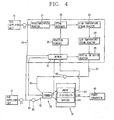
- Figure 4 is a schematic view of a fuel cell system configuration in accordance with yet another example embodiment of the present invention;
- Figure 5 is a perspective cut-away view of an example heat exchange unit; and
- Figure 6 is a perspective cut-away view of another example heat exchange unit.
- As noted above, example embodiments of the present invention relate to a fuel cell system that includes a heat exchange unit. In preferred embodiments, the heat exchange unit is incorporated within the fuel cell system in a manner so as to control the temperature of the fuel and/or the air that is supplied to a stack unit. Controlling the temperature of the fuel and/or air supplied to the stack unit can help extend the lifespan of the stack unit by helping to avoid damage that can be caused by condensate being supplied to the stack unit.
- Reference will now be made to some example embodiments of the present invention, relevant details of which are disclosed in Figures 2-6. In Figures 2-6, elements that are identical to those disclosed in Figure 1 have identical reference numerals, and a detailed explanation thereof is omitted.
- With particular reference now to Figures 2-4, schematic views of three separate example fuel cell system configurations are disclosed. While other configurations could be used, each of the example fuel cell systems disclosed in Figures 2-4 includes a fuel
cell supplying unit 10, anair supplying unit 12, a reformingunit 20, astack unit 30, apower converter 40, a gas-liquid separator 50, and ahumidifier 60, each of which functions substantially as described above in connection with Figure 1. As is disclosed in the example implementations of Figures 2-4, thehumidifier 60 is installed between theair supplying unit 12 and thestack unit 30. Theair supplying unit 12 and thehumidifier 60 are connected through a firstair supplying line 61, and thehumidifier 60 and thestack unit 30 are connected through a secondair supplying line 62. The gas-liquid separator 50 is installed between the reformingunit 20 and thestack unit 30. The reformingunit 20 and the gas-liquid separator 50 are connected through a firstfuel supplying line 51, and the gas-liquid separator 50 and thestack unit 30 are connected through a secondfuel supplying line 52. - Unlike the fuel cell system disclosed in Figure 1, however, each of the fuel cell systems disclosed in Figures 2-4 includes a
heat exchange unit 70, two examples of which are disclosed in Figures 5 and 6. In the example fuel cell configuration of Figure 2, the secondair supplying line 62 runs through theheat exchange unit 70. In the example fuel cell configuration of Figure 3, the secondfuel supplying line 52 runs through theheat exchange unit 70. In the example fuel cell configuration of Figure 4, both the secondfuel supplying line 52 and the secondair supplying line 62 run through theheat exchange unit 70. - With continuing reference to Figures 2-4 and with particular reference now also to Figures 5 and 6, additional details of example implementations of a
heat exchange unit 70 are disclosed. As disclosed in Figures 5 and 6, theheat exchange unit 70 can include acasing 71, or other similar structure, that is configured so as to provide an airtight interior portion. Off gas discharged from theburner 27 can be supplied to the interior portion through, for example, an offgas suction line 72. Example embodiments of each illustratedheat exchange unit 70 also includes an offgas discharge line 73, or similar structure, that is configured to discharge the off gas from the interior portion of thecasing 71. - As disclosed in Figures 5 and 6, a portion of the second
air supplying line 62 and a portion of the secondfuel supplying line 52 can each be arranged to pass through the interior portion defined by casing 71. In one embodiment, the secondair supplying line 62 runs through the interior of thecasing 71 in a substantially straight line. The secondfuel supplying line 52 also runs through the interior of thecasing 71, but instead of running in a substantially straight line, the secondfuel supplying line 52 can be implemented so as to substantially surround the periphery of the secondair supplying line 62, for example in a generally spiral fashion. As noted above, however, theheat exchange unit 70 need not include both the secondfuel supplying line 52 and the secondair supplying line 62. Instead, thehead exchange unit 70 may include only the secondair supplying line 62, as disclosed in Figure 2, or only the secondfuel supplying line 52, as disclosed in Figure 3, depending on the objectives and needs of a particular implementation. Also, other configurations and routing schemes could be used than those shown, again, depending on the particular implementation. - The
heat exchange unit 70 therefore places a portion of the secondair supplying line 62 and/or a portion of the secondfuel supplying line 52 in contact with the off gas generated in theburner 27 and supplied to the interior defined by casing 71. Where the temperature of the off gas is higher than the temperature of the air flowing through the secondair supplying line 62 but lower than the temperature of the hydrogen gas flowing through the secondfuel supplying line 52, this contact with the off gas rapidly increases the relatively low temperature of the air and rapidly decreases the relatively high temperature of the hydrogen gas. - In order to control the temperatures of the fuel and/or the air supplied to the
stack unit 30 through the secondfuel supplying line 52 and the secondair supplying line 62, respectively, the secondfuel supplying line 52 and/or the secondair supplying line 62 can be disposed in the interior defined by casing 71 in various shapes and configurations. - For example, to lower the temperature of the hydrogen gas supplied to the
stack unit 30 through the secondfuel supplying line 52, the length of the secondfuel supplying line 52 within the interior of casing 71 can be increased by densely arranging the secondfuel supplying line 52 within the interior in a substantially spiral shape, as disclosed in Figure 6. In addition, to raise the temperature of the air supplied to thestack unit 30 through the secondair supplying line 62, the length of the secondair supplying line 62 within theheat exchange unit 70 can be increased by curving the secondair supplying line 62 within thecasing 71. The hydrogen gas that is supplied to the interior of casing 71 through the secondfuel supplying line 52 can thus be cooled to a predetermined temperature, and supplied to theanode 31 of thestack unit 30. At the same time, the air supplied to thecasing 71 through the secondair supplying line 62 can thus be heated to a predetermined temperature, and supplied to thecathode 33 of thestack unit 30. - In one example embodiment, additional heat exchange between the second
fuel supplying line 52 and the secondair supplying line 62 is provided by placing the outer surface of the secondfuel supplying line 52 and the outer surface of the secondair supplying line 62 in contact with each other. - As the
stack unit 30 is supplied with the hydrogen gas and air having the predetermined optimum temperatures due to the temperature control performed by theheat exchange unit 70, the hydrogen gas H2 is supplied to theanode 31, and ionized and oxidized into hydrogen ions H+ and electrons e- by electrochemical oxidation. The ionized hydrogen ions are transferred to thecathode 33 through anelectrolyte film 32, and the electrons are transferred through theanode 31, thereby generating electricity, heat and water. Electricity generated in thestack unit 30 can then converted by thepower converter 40, depending on the particular electrical power needs. - As the present invention may be embodied in several forms without departing from the spirit or essential characteristics thereof, it should also be understood that the above-described embodiments are not limited by any of the details of the foregoing description, unless otherwise specified, but rather should be construed broadly within its spirit and scope as defined in the appended claims, and therefore all changes and modifications that fall within the metes and bounds of the claims, or equivalents of such metes and bounds are therefore intended to be embraced by the appended claims.
Claims (11)
- A fuel cell system, comprising:a fuel supplying unit configured to supply a fuel;an air supplying unit configured to supply air via an air supplying line;a reforming unit configured to receive the fuel from the fuel supplying unit and generate hydrogen floating gas to a fuel supplying line, the reforming unit including a burner;a stack unit configured to generate electric energy by an electrochemical reaction between the air supplied from the air supplying unit and the hydrogen floating gas supplied from the reforming unit; anda heat exchange unit including a substantially airtight interior to which an off gas generated in the burner is supplied, wherein at least a portion of the fuel supplying line is arranged to pass through at least a portion of the interior.
- The fuel cell system as claimed in claim 1, further comprising:a humidifier configured to supply moisture to the air supplying line; anda gas-liquid separator configured to separate gas and liquid is provided at the fuel supplying line.
- The fuel cell system as claimed in claim 2, wherein the heat exchange unit is disposed at a location on the fuel supplying line so as to be disposed between the gas-liquid separator and the stack unit.
- A fuel cell system, comprising:a fuel supplying unit configured to supply a fuel;an air supplying unit configured to supply air via an air supplying line;a reforming unit configured to receive the fuel from the fuel supplying unit and to generate hydrogen floating gas, and supplying the hydrogen floating gas through a fuel supplying line, the reforming unit including a burner;a stack unit configured to generate electric energy by an electrochemical reaction between the air supplied through the air supplying line and the hydrogen floating gas supplied through the fuel supplying line; anda heat exchange unit including a substantially airtight interior to which an off gas generated in the burner is supplied, wherein at least a portion of the air supplying line is arranged to pass through at least a portion of the interior.
- The fuel cell system as claimed in claim 4, further comprising:a humidifier configured to supply moisture to the air supplying line; anda gas-liquid separator configured to separate gas and liquid is provided at the fuel supplying line.
- The fuel cell system as claimed in claim 5, wherein the heat exchange unit is disposed at a point on the fuel supplying line so as to be disposed between the humidifier and the stack unit.
- A fuel cell system, comprising:a fuel supplying unit configured to supply a fuel;an air supplying unit configured to supply air via an air supplying line;a reforming unit configured to receive the fuel from the fuel supplying unit and to generate hydrogen floating gas, and supplying the hydrogen floating gas through a fuel supplying line, the reforming unit including a burner;a stack unit configured to generate electric energy by an electrochemical reaction between the air supplied through the air supplying line and the hydrogen floating gas supplied through the fuel supplying line; anda heat exchange unit including a substantially airtight interior to which an off gas generated in the burner is supplied, wherein at least a portion of the fuel supplying line and at least a portion of the air supplying line are configured to pass through at least a portion of the interior.
- The fuel cell system as claimed in claim 7, further comprising:a humidifier configured to supply moisture to the air supplying line; anda gas-liquid separator configured to separate gas and liquid is provided at the fuel supplying line.
- The fuel cell system as claimed in claim 8, wherein the heat exchange unit is disposed at a point on the fuel supplying line so as to be disposed between the humidifier and the stack unit and at a point on the air supplying line so as to be disposed between the gas-liquid separator and the stack unit.
- The fuel cell system as claimed in claim 7, wherein at least a portion of the air supplying line passes through the interior so as to be oriented in a substantially straight line, and at least a portion of the fuel supplying line passes through the interior so as to be oriented around a periphery of the air supplying line in a substantially spiral shape.
- The fuel cell system as claimed in claim 10, wherein at least a portion of an outer surface of the air supplying line and an outer surface of the fuel supplying line are in contact with each other within the interior.
Applications Claiming Priority (1)
| Application Number | Priority Date | Filing Date | Title |
|---|---|---|---|
| KR1020050117696A KR100761265B1 (en) | 2005-12-05 | 2005-12-05 | Fuel cell system |
Publications (2)
| Publication Number | Publication Date |
|---|---|
| EP1793441A2 true EP1793441A2 (en) | 2007-06-06 |
| EP1793441A3 EP1793441A3 (en) | 2007-07-25 |
Family
ID=37762242
Family Applications (1)
| Application Number | Title | Priority Date | Filing Date |
|---|---|---|---|
| EP06025039A Withdrawn EP1793441A3 (en) | 2005-12-05 | 2006-12-04 | Fuel cell system including a heat exchanger for preheating fuel and/or air using off-gas of the reformer burner |
Country Status (5)
| Country | Link |
|---|---|
| US (1) | US20070128480A1 (en) |
| EP (1) | EP1793441A3 (en) |
| KR (1) | KR100761265B1 (en) |
| CN (1) | CN1979933A (en) |
| RU (1) | RU2325011C1 (en) |
Cited By (1)
| Publication number | Priority date | Publication date | Assignee | Title |
|---|---|---|---|---|
| EP2110880A1 (en) * | 2008-04-15 | 2009-10-21 | Samsung SDI Co., Ltd. | Fuel cell system and method of controlling the same |
Families Citing this family (3)
| Publication number | Priority date | Publication date | Assignee | Title |
|---|---|---|---|---|
| CN102544554B (en) * | 2012-02-13 | 2014-10-29 | 欧阳洵 | Fuel cell system |
| CN105428675B (en) * | 2015-11-11 | 2018-11-02 | 西安石油大学 | A kind of petroleum collection system and method based on associated gas |
| JP7144369B2 (en) * | 2019-07-10 | 2022-09-29 | 日立造船株式会社 | fuel cell system |
Citations (5)
| Publication number | Priority date | Publication date | Assignee | Title |
|---|---|---|---|---|
| EP0429958A2 (en) * | 1989-11-25 | 1991-06-05 | Ishikawajima-Harima Heavy Industries Co., Ltd. | Power generation system using molten carbonate fuel cell |
| US5360679A (en) * | 1993-08-20 | 1994-11-01 | Ballard Power Systems Inc. | Hydrocarbon fueled solid polymer fuel cell electric power generation system |
| WO2002032807A1 (en) * | 2000-10-18 | 2002-04-25 | Emitec Gesellschaft Für Emissionstechnologie Mbh | Method for obtaining hydrogen from hydrocarbons |
| DE10160474A1 (en) * | 2001-12-08 | 2003-06-18 | Ballard Power Systems | Process for switching off a methanol fuel cell system composed of a vaporizer, a reformer and a water separator, comprises reducing the water to fuel mixing ratio and/or lowering the operating temperature |
| EP1517389A1 (en) * | 2003-09-15 | 2005-03-23 | Balcke-Dürr GmbH | Reformer unit for fuel cells for reforming hydrocarbon feed gases into hydrogen-containing fuel gases |
Family Cites Families (6)
| Publication number | Priority date | Publication date | Assignee | Title |
|---|---|---|---|---|
| US7216696B2 (en) * | 1999-09-23 | 2007-05-15 | Ferraro Joseph C | External flue heat exchangers |
| JP3882485B2 (en) * | 2000-09-04 | 2007-02-14 | 日産自動車株式会社 | Fuel cell vehicle |
| KR100662759B1 (en) * | 2000-12-29 | 2007-01-02 | 주식회사 엘지이아이 | Fuel cell driving type cleaner |
| JP4374782B2 (en) * | 2001-01-18 | 2009-12-02 | トヨタ自動車株式会社 | In-vehicle fuel cell system and control method thereof |
| US7049016B2 (en) * | 2001-11-08 | 2006-05-23 | Nissan Motor Co., Ltd. | Fuel cell system and its startup control |
| US7169495B2 (en) * | 2003-05-06 | 2007-01-30 | Versa Power Systems, Ltd. | Thermally integrated SOFC system |
-
2005
- 2005-12-05 KR KR1020050117696A patent/KR100761265B1/en active IP Right Grant
-
2006
- 2006-11-30 US US11/565,377 patent/US20070128480A1/en not_active Abandoned
- 2006-12-04 RU RU2006142822/09A patent/RU2325011C1/en not_active IP Right Cessation
- 2006-12-04 EP EP06025039A patent/EP1793441A3/en not_active Withdrawn
- 2006-12-05 CN CNA2006101640246A patent/CN1979933A/en active Pending
Patent Citations (5)
| Publication number | Priority date | Publication date | Assignee | Title |
|---|---|---|---|---|
| EP0429958A2 (en) * | 1989-11-25 | 1991-06-05 | Ishikawajima-Harima Heavy Industries Co., Ltd. | Power generation system using molten carbonate fuel cell |
| US5360679A (en) * | 1993-08-20 | 1994-11-01 | Ballard Power Systems Inc. | Hydrocarbon fueled solid polymer fuel cell electric power generation system |
| WO2002032807A1 (en) * | 2000-10-18 | 2002-04-25 | Emitec Gesellschaft Für Emissionstechnologie Mbh | Method for obtaining hydrogen from hydrocarbons |
| DE10160474A1 (en) * | 2001-12-08 | 2003-06-18 | Ballard Power Systems | Process for switching off a methanol fuel cell system composed of a vaporizer, a reformer and a water separator, comprises reducing the water to fuel mixing ratio and/or lowering the operating temperature |
| EP1517389A1 (en) * | 2003-09-15 | 2005-03-23 | Balcke-Dürr GmbH | Reformer unit for fuel cells for reforming hydrocarbon feed gases into hydrogen-containing fuel gases |
Cited By (2)
| Publication number | Priority date | Publication date | Assignee | Title |
|---|---|---|---|---|
| EP2110880A1 (en) * | 2008-04-15 | 2009-10-21 | Samsung SDI Co., Ltd. | Fuel cell system and method of controlling the same |
| US8492039B2 (en) | 2008-04-15 | 2013-07-23 | Samsung Sdi Co., Ltd. | Fuel cell system and method of controlling the same |
Also Published As
| Publication number | Publication date |
|---|---|
| KR20070058884A (en) | 2007-06-11 |
| RU2325011C1 (en) | 2008-05-20 |
| KR100761265B1 (en) | 2007-10-04 |
| US20070128480A1 (en) | 2007-06-07 |
| CN1979933A (en) | 2007-06-13 |
| EP1793441A3 (en) | 2007-07-25 |
Similar Documents
| Publication | Publication Date | Title |
|---|---|---|
| US7799482B2 (en) | Stack of generators and fuel cell system having the same | |
| US7537851B2 (en) | Fuel cell system including separator having cooling water flow channels | |
| US8486162B2 (en) | Reformer for fuel cell system and fuel cell system having the same | |
| JP4956946B2 (en) | Fuel cell | |
| US7485384B2 (en) | Cooling apparatus for fuel cell and fuel cell system having the same | |
| US20100062302A1 (en) | Metal support and solid oxide fuel cell including the same | |
| EP1793441A2 (en) | Fuel cell system including a heat exchanger for preheating fuel and/or air using off-gas of the reformer burner | |
| EP1995814B1 (en) | Fuel cell stack | |
| JP2006236599A (en) | Water recovery method for fuel cell power generator | |
| JP2007005134A (en) | Steam generator and fuel cell | |
| KR20060022868A (en) | Fuel cell system and stack | |
| US20110027685A1 (en) | Fuel cell comprising multi-tubular support | |
| KR100519414B1 (en) | Molten carbonate fuel cell with simplified central distribution separator | |
| KR100761267B1 (en) | Fuel cell system | |
| KR20100048553A (en) | Seperator for high temperature fuel cells | |
| KR100627389B1 (en) | Fuel cell system and stack of the same | |
| KR100570685B1 (en) | Carbon monoxide remover, and fuel cell system comprising the carbon monoxide remover | |
| KR100515308B1 (en) | Fuel cell system | |
| KR101387756B1 (en) | System for operation of multi fuel cell having thermoelectric element | |
| KR100529081B1 (en) | Fuel cell system and stack used thereto | |
| KR100446781B1 (en) | Electrode structure for fuel cell | |
| KR20060020024A (en) | Fuel cell system and stack | |
| KR20060018476A (en) | Fuel cell | |
| KR20050025498A (en) | Optimum operation apparatus of fuel cell | |
| KR20060107152A (en) | Fuel tank and stack of fuel cell system and fuel cell system having thereof |
Legal Events
| Date | Code | Title | Description |
|---|---|---|---|
| PUAI | Public reference made under article 153(3) epc to a published international application that has entered the european phase |
Free format text: ORIGINAL CODE: 0009012 |
|
| AK | Designated contracting states |
Kind code of ref document: A2 Designated state(s): AT BE BG CH CY CZ DE DK EE ES FI FR GB GR HU IE IS IT LI LT LU LV MC NL PL PT RO SE SI SK TR |
|
| AX | Request for extension of the european patent |
Extension state: AL BA HR MK YU |
|
| PUAL | Search report despatched |
Free format text: ORIGINAL CODE: 0009013 |
|
| AK | Designated contracting states |
Kind code of ref document: A3 Designated state(s): AT BE BG CH CY CZ DE DK EE ES FI FR GB GR HU IE IS IT LI LT LU LV MC NL PL PT RO SE SI SK TR |
|
| AX | Request for extension of the european patent |
Extension state: AL BA HR MK YU |
|
| 17P | Request for examination filed |
Effective date: 20071203 |
|
| 17Q | First examination report despatched |
Effective date: 20080114 |
|
| AKX | Designation fees paid |
Designated state(s): AT CH DE FR GB LI |
|
| STAA | Information on the status of an ep patent application or granted ep patent |
Free format text: STATUS: THE APPLICATION IS DEEMED TO BE WITHDRAWN |
|
| 18D | Application deemed to be withdrawn |
Effective date: 20080526 |