EP1795875A1 - An apparatus for measuring volume of liquid in a vessel - Google Patents
An apparatus for measuring volume of liquid in a vessel Download PDFInfo
- Publication number
- EP1795875A1 EP1795875A1 EP05077814A EP05077814A EP1795875A1 EP 1795875 A1 EP1795875 A1 EP 1795875A1 EP 05077814 A EP05077814 A EP 05077814A EP 05077814 A EP05077814 A EP 05077814A EP 1795875 A1 EP1795875 A1 EP 1795875A1
- Authority
- EP
- European Patent Office
- Prior art keywords
- vessel
- float
- liquid
- volume
- valve
- Prior art date
- Legal status (The legal status is an assumption and is not a legal conclusion. Google has not performed a legal analysis and makes no representation as to the accuracy of the status listed.)
- Granted
Links
- 239000007788 liquid Substances 0.000 title claims abstract description 87
- 238000012545 processing Methods 0.000 claims abstract description 18
- 238000000034 method Methods 0.000 claims abstract description 9
- 210000002700 urine Anatomy 0.000 claims description 15
- 239000012530 fluid Substances 0.000 claims description 12
- 230000004044 response Effects 0.000 claims description 4
- 230000005484 gravity Effects 0.000 claims description 3
- 230000003993 interaction Effects 0.000 claims description 3
- 230000000694 effects Effects 0.000 claims description 2
- 230000008569 process Effects 0.000 abstract description 3
- 238000005259 measurement Methods 0.000 description 14
- 239000000463 material Substances 0.000 description 4
- 230000003287 optical effect Effects 0.000 description 4
- 239000002184 metal Substances 0.000 description 3
- 208000004880 Polyuria Diseases 0.000 description 2
- 230000035619 diuresis Effects 0.000 description 2
- 230000001939 inductive effect Effects 0.000 description 2
- 229920000642 polymer Polymers 0.000 description 2
- 230000003746 surface roughness Effects 0.000 description 2
- 210000003708 urethra Anatomy 0.000 description 2
- FAPWRFPIFSIZLT-UHFFFAOYSA-M Sodium chloride Chemical compound [Na+].[Cl-] FAPWRFPIFSIZLT-UHFFFAOYSA-M 0.000 description 1
- 230000002411 adverse Effects 0.000 description 1
- 239000003570 air Substances 0.000 description 1
- QVGXLLKOCUKJST-UHFFFAOYSA-N atomic oxygen Chemical compound [O] QVGXLLKOCUKJST-UHFFFAOYSA-N 0.000 description 1
- 239000008280 blood Substances 0.000 description 1
- 210000004369 blood Anatomy 0.000 description 1
- 230000001427 coherent effect Effects 0.000 description 1
- 238000004891 communication Methods 0.000 description 1
- 150000001875 compounds Chemical class 0.000 description 1
- 238000011109 contamination Methods 0.000 description 1
- 239000007799 cork Substances 0.000 description 1
- 239000003814 drug Substances 0.000 description 1
- 229920002457 flexible plastic Polymers 0.000 description 1
- 239000007789 gas Substances 0.000 description 1
- 230000036541 health Effects 0.000 description 1
- 238000011326 mechanical measurement Methods 0.000 description 1
- 230000027939 micturition Effects 0.000 description 1
- 238000012544 monitoring process Methods 0.000 description 1
- 239000001301 oxygen Substances 0.000 description 1
- 229910052760 oxygen Inorganic materials 0.000 description 1
- 229920003023 plastic Polymers 0.000 description 1
- 239000004033 plastic Substances 0.000 description 1
- 239000011780 sodium chloride Substances 0.000 description 1
- 239000012780 transparent material Substances 0.000 description 1
Images


Classifications
-
- G—PHYSICS
- G01—MEASURING; TESTING
- G01F—MEASURING VOLUME, VOLUME FLOW, MASS FLOW OR LIQUID LEVEL; METERING BY VOLUME
- G01F23/00—Indicating or measuring liquid level or level of fluent solid material, e.g. indicating in terms of volume or indicating by means of an alarm
- G01F23/30—Indicating or measuring liquid level or level of fluent solid material, e.g. indicating in terms of volume or indicating by means of an alarm by floats
- G01F23/64—Indicating or measuring liquid level or level of fluent solid material, e.g. indicating in terms of volume or indicating by means of an alarm by floats of the free float type without mechanical transmission elements
- G01F23/68—Indicating or measuring liquid level or level of fluent solid material, e.g. indicating in terms of volume or indicating by means of an alarm by floats of the free float type without mechanical transmission elements using electrically actuated indicating means
- G01F23/686—Indicating or measuring liquid level or level of fluent solid material, e.g. indicating in terms of volume or indicating by means of an alarm by floats of the free float type without mechanical transmission elements using electrically actuated indicating means using opto-electrically actuated indicating means
-
- G—PHYSICS
- G01—MEASURING; TESTING
- G01F—MEASURING VOLUME, VOLUME FLOW, MASS FLOW OR LIQUID LEVEL; METERING BY VOLUME
- G01F23/00—Indicating or measuring liquid level or level of fluent solid material, e.g. indicating in terms of volume or indicating by means of an alarm
- G01F23/22—Indicating or measuring liquid level or level of fluent solid material, e.g. indicating in terms of volume or indicating by means of an alarm by measuring physical variables, other than linear dimensions, pressure or weight, dependent on the level to be measured, e.g. by difference of heat transfer of steam or water
- G01F23/28—Indicating or measuring liquid level or level of fluent solid material, e.g. indicating in terms of volume or indicating by means of an alarm by measuring physical variables, other than linear dimensions, pressure or weight, dependent on the level to be measured, e.g. by difference of heat transfer of steam or water by measuring the variations of parameters of electromagnetic or acoustic waves applied directly to the liquid or fluent solid material
- G01F23/284—Electromagnetic waves
- G01F23/292—Light, e.g. infrared or ultraviolet
-
- G—PHYSICS
- G01—MEASURING; TESTING
- G01F—MEASURING VOLUME, VOLUME FLOW, MASS FLOW OR LIQUID LEVEL; METERING BY VOLUME
- G01F23/00—Indicating or measuring liquid level or level of fluent solid material, e.g. indicating in terms of volume or indicating by means of an alarm
- G01F23/30—Indicating or measuring liquid level or level of fluent solid material, e.g. indicating in terms of volume or indicating by means of an alarm by floats
- G01F23/76—Indicating or measuring liquid level or level of fluent solid material, e.g. indicating in terms of volume or indicating by means of an alarm by floats characterised by the construction of the float
Definitions
- the present invention relates to an apparatus for measuring the volume of liquid in a vessel, in particular optic based measurement of volume of liquid, such as body liquids of bedridden patients.
- the present invention also relates to a method of measuring volume of liquid in a vessel.
- EP 0 398 890 discloses an apparatus for mechanical measuring of the volume of urine from bedridden patients.
- the apparatus comprises a measuring vessel with a valve body being displaceable therein, the valve body being divided into a reception chamber and an overflow chamber.
- the urine from the patient enters into the reception chamber and is measured via a suitable measurement scale provided on the outside of the valve body, and the volume of the collected urine can be read at any given time.
- apparatuses using mechanical measurement of the volume require a nurse reading the volume with regular intervals and for writing down the present value of the volume manually.
- the manual reading is done by changing personal during a 24 hours shift at the hospital inducing the risk of inaccurate values of the volume of present urine discharged into the vessel.
- US 5,257,090 discloses a laser diode distance measurement device including a laser diode assembly comprising a laser diode and photodiode emitting light to a lens providing collimated light incident on a float being covered with reflective tape on its top surface. The light is reflected from the float back to the laser diode assembly causing the assembly to provide a signal having magnitude pulses (due to coherent interference) on a line to a liquid level measurement circuit related to a distance L to the float.
- DE 42 17 669 discloses another electronic measuring of volume in e.g. a gas tank, wherein a light source is mounted above the tank and directs a light beam vertically into the tank.
- a reflecting float having a conical upper surface defines the fluid level and the upper surface of the float reflects light to an array of photocells positioned at one side of the top of the tank.
- the position of the reflected beam on the array relates to the position of the reflecting float.
- the float is held in a vertical guide having a slit for directing the light to the one of the photocells in the array of photocells.
- the volume of liquid is determined from which photocell in the array of photocells the light is received.
- the abovementioned apparatuses use a float with a 100% reflective surface, which requires the float to be kept in precise vertical position in order to ensure that the measuring is correct. If the apparatus and thus the float are tilted away from vertical position the measurement of the volume of liquid present in the vessel divert from the actual volume present. In US 5,257,090 the float reflects the light in a direction diverting away from the detecting laser assembly resulting in an incorrect measurement of the actual volume of liquid. In some cases the float may even tilted in such a degree as to result in that the laser assembly never receives the light reflected by the surface of the float.
- An objective of the present invention is to provide an improved apparatus to at least partly overcome the disadvantages and drawbacks of the known apparatuses presented above.
- said apparatus for collecting and measuring volume of liquids comprising; a vessel having a liquid inlet and a liquid outlet, said vessel comprising a guiding member defining a vertical movement guidance for a float adapted to be disposed at a level equal to the surface of a liquid in the vessel, a light source assembly being provided above said float and adapted to emit a light beam towards a surface of said float, said surface of the float being diffuse reflective, the apparatus further comprising sensing means for sensing diffused light reflected from said float surface and processing means for receiving and processing input from said sensing means based on the diffused reflected light so as to calculate the level position of the float and thereby the volume of liquid present in the vessel.
- the diffuse reflective surface means that the portion of light that falls on the float surface is radiated diffusely in all directions.
- the light beam will be reflected in all directions and not just in one direction, which is the case if the surface is not diffuse, for instance if the surface is very smooth, such as a mirror.
- the apparatus is not sensitive in relation to the vertical orientation of the vessel, and a correct measurement will be obtained independent of the vertical orientation of the vessel.
- the efficiency of the diffuse reflection from the float surface depends i.a. on the color and the smoothness of the surface.
- the surface is preferably in a light color and uneven, which means that the surface preferably is rough and defined by "valleys and hills" each giving a different angle of reflection in relation to the substantially vertical incoming light beam from the light source assembly.
- the float may be made of any suitable floating material, such as plastic, cork or air-filled metal.
- the float may have any suitable shape as long as its color and surface roughness is sufficiently diffuse reflective, cf. above, and the shape may for example be flat, concave or convex.
- the light source may be a laser.
- a light source such as a laser the measurements is not substantial influenced by light from the surrounding of the apparatus.
- the light source may in another embodiment be a UV-light source.
- the float may be positioned inside the guiding member.
- the guiding member guides the float in its periphery edges while the float is still able to tilt within the guiding member in order to follow the liquid surface despite any tilting movements of the apparatus.
- the periphery of the float may be congruous to the shape of the guiding means.
- the guiding member may in another embodiment comprise a rod-shaped member, and the float may be positioned so that the guiding member extends through the centre of the float. In this way the float can slit along the rod-shaped member and is guided at the edges of such.
- the float may be positioned inside the guiding member, for example being a tube-like member not open for fluid entering the vessel, and wherein a further floating element is disposed on the surface of the liquid outside the guiding member, the floating element and the float being at the same level by means of magnetic interaction between them.
- the float will then always be at the level of the liquid surface while not being in contact with the liquid, which minimise the risk of the float getting locked inside the guiding member.
- the floating element may be a magnetic ring floating on the liquid surface and surrounding the tube-like guiding member, both the floating element and the float being magnetic.
- the level position of the float is preferably determined by optical laser triangulation, and the sensing means (often called the "light-receiving element") is preferably a PSD (Position Sensitive Detector) sensor or a CCD (Charge Couple Device) sensor including a lens positioned in front of the sensor for focusing the light reflected from the surface of the float.
- PSD Position Sensitive Detector
- CCD Charge Couple Device
- the sensor determines the position of the float by measuring the light reflected from its surface.
- the light source assembly emits a light spot onto the float.
- An optical lens system focuses the reflected light onto a light sensitive device (receiving element), which may be provided in the sensor head. If the float changes its position from a reference point, the position of the projected spot on the detector changes too. Thus, it is possible to calculate the position of the float based on the reflected incoming light.
- the PSD sensor is an analog sensor that relies on current generated in a photodiode.
- the output current is proportional to the reflected light spot's position on the sensor.
- the CCD sensor is a digital pixel-based array sensor that preferably has 1024 discrete voltages representing the amount of light on each pixel. Thus, it is possible to view the intensity distribution of an imaged spot, and image processing is then incorporated for the linear triangulation measurement.
- the apparatus may be used to measure volume of liquid for any applications, but it is preferably used for measuring volume of body liquids.
- the apparatus is used for measuring urine (diuresis), and the inlet of the vessel can be coupled to a catheter inserted in the bladder of a bedridden patient.
- the vessel comprises a guiding member, which is open for the liquid in the vessel, such that the float will float upwards or downwards inside the guiding member when the vessel is filled or emptied, respectively.
- the guiding member may in one embodiment be in the form of a tube, preferably a transparent tube. Furthermore the tube may in another embodiment have slots through which the liquid inside the vessel can enter. The float may in this way float freely inside the tube so as to ensure that the float is not locked in the tube.
- the light assembly may as mentioned above be any kind of laser source generating a laser beam towards the surface of the float.
- a lens may in one embodiment be provided in front of the laser for collimating the light from the laser.
- the apparatus may further comprise an accelerometer adapted to measure the force of gravity and send an input to the processing means indicating the angle to vertical of the vessel to be used in calculating the volume of liquid present in the vessel.
- the apparatus may comprise a first valve for closing said inlet.
- the first valve may be adapted to close the inlet in response to an input received from the accelerometer and/or processing means when the vessel is tilted a given angle from vertical. In this way liquid is hindered from flowing back through the inlet of the vessel and into the catheter again e.g. when the apparatus placed beside a bedridden patient.
- the apparatus can be placed horizontally without any outflow of liquid, which is very helpful, if the patient needs to get out of bed and therefore must manipulate the vessel.
- the apparatus according to the present invention may comprise a collection chamber connected to the liquid outlet of the vessel for collecting liquid emptied from the vessel.
- the liquid is emptied into the collection chamber, which preferably is made of a transparent flexible plastic and is disposable.
- a pipe may provide the fluid connection between the collection chamber and the vessel, and the pipe may define a loop with a highest point being movable from above liquid level to below liquid level in the vessel so as to enable emptying of said vessel by means of siphon principle.
- a simple mechanical emptying arrangement is provided.
- the loop is lifted and lowered from outside the vessel electronically by a control unit.
- the fluid connection between the collection chamber and vessel may comprise a second valve for opening in order to empty the vessel and subsequently for closing the fluid connection.
- Said first and/or second valve may be manually or electronic controlled.
- the first valve may be controllable in relation to the second valve, such that the first valve is closed when the second valve is open and vice versa, i.a. ensuring that no liquid can enter the vessel during emptying thereof, which is very important for measuring the precise volume of liquid coming from a patient.
- a patient is urinating while emptying this new amount of urine, which has not yet be measured, will only be allowed access to the vessel through the inlet when the emptying process of the vessel is completed. In this way the new urine is measured accurately.
- the apparatus including the collection chamber constitutes preferably an entirely hermetically sealed system in order to eliminate or at least minimise the risk of contamination, which otherwise would have adverse consequences for the patients health.
- the processing means may be able to store the amount of urine emptied into the collection chamber so as to add it to the amount continuously measured in the vessel and display the total amount of urine delivered from a patient.
- the processing means may control the second valve in response to the position of the float, so as to open the second valve automatically at a predetermined position of the float and thereby emptying the vessel when the volume of liquid reaches a predetermined value.
- the first and/or second valve is preferably operated by magnetic force being controlled by a servomotor, or by a mechanical device controlled by an actuator.
- the processing means may comprise a microprocessor, and a display for digital displaying of the volume present in the vessel may also be provided.
- the data of the volume may be stored in storage means and can be loaded for later use, and the data can be printed.
- the display may allow the user via a keyboard or a touch screen to enter values, such as maximum level value before emptying the vessel.
- the vessel may be detachable from the other parts of the apparatus, such that the vessel and collection chamber is disposable.
- the apparatus may additionally display information about the temperature, the bladder pressure and/or oxygen level of the patient.
- the apparatus may have measuring equipment for analysing the colour or the transparency of the urine. In this way other measures such as the temperature, blood, the concentration of different elements, compounds etc. may be analysed in the urine.
- the apparatus may be wired or wireless to connected to other data collecting and processing devices.
- the present invention relates to a method of measuring a volume of liquid in a vessel by;
- the method may further comprise measuring the tilting of the vessel from vertical by means of an accelerometer to correct for the tilting effect when calculating the level position of the float.
- the present invention relates to the use of an apparatus according to the first aspect for measuring the volume of body liquids, such as urine.
- the apparatus according to the invention could be used in any application for measuring a volume of liquid in a vessel/container/tank, such as for example level of petrol in petrol tanks of vehicles or at petrol stations, during inducing medicaments, saline or the like into a human being.
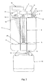
- the apparatus of Fig. 1 show an electronic measuring of the amount of liquid present in the apparatus e.g. urine from a human being.
- the apparatus comprises a vessel 1 having an inlet 2 through which the liquid 6 enters into the vessel.
- the inlet can be connected to a catheter 3 positioned in the urethra of a patient (being any mammalian body).
- the inlet is closed and opened by a valve 12 controlled by a servomotor 14, e.g. using magnetic force to shut off the valve.
- the inlet 2 is closed by the first valve e.g. when emptying the vessel and opened again when the emptying process is completed.
- the first valve 12 may in another embodiment be closed manually.
- a guiding member is in Fig. 1 shown in the form of a tube 4 is arranged inside the vessel 1 and functions as guidance for the vertical movement of a float 5 positioned in the tube.
- the guidance is needed in order for the laser beam to enlightened the diffused surface of the float, and thereby that some of the diffused light is emitted into the lens and sensor.
- the tube 4 is open for the liquid in the vessel, and the opening can be provided at the bottom as shown or for example as slots in the sidewall.
- the filling of liquid into the vessel will cause some turbulence with the tube. By having a lot of slots the filling of the vessel and tube with liquid is done more rapidly and the float is in this way more quickly stable for a more accurate measurement.
- the float 5 floats on the surface 6 of the liquid (urine) in the vessel and follows the surface of the liquid as shown with dotted lines.
- a laser unit 7 is positioned above said tube 5 and emits a laser beam towards the surface of the float 5.
- the laser beam will be reflected in a plurality of directions, which ensures that some of the reflected light always will be focused by the lens 15 in front of the sensor 8 sensing the reflected light.
- the sensor 8 will detect the position of the float even if the vessel is tilted within a given angle in relation to vertical, such as up to 45 degrees from vertical.
- the sensor is preferably a PSD or CCD sensor including a lens in front of the sensor for focusing/collimating the light.
- the light used in the apparatus may be IR, UV or the like.
- the choice of light source may vary depending on the surrounding light.
- the laser beam will still hit the surface of the float just at another angle/position. Since the float has a diffused reflecting surface some of the laser beam is emitted further on to the sensor, whereby the processing means together with the sensor is able to determine to liquid level of the vessel. Due to the fact that the float is guided by the guidance member and the surface of the float is diffuse reflecting, the emitted light of the laser is always transmitted to the sensor.
- a three-axis accelerometer 9 may be provided in the apparatus for measuring the force of gravity in order to determine the tilt and direction of the vessel 1, which is used to correct for the vertical position when calculating the level of the float 5.
- the processor 18 is able to correct the measurement if the apparatus has been tilted during the measuring.
- the senor 8 Based on the reflected light, the sensor 8 will send an input to a processor 18 (microprocessor), which then calculates the level position of the float based on input from the sensor and by the accelerometer.
- a processor 18 microprocessor
- a focusing lens 15,19 is positioned in front of the laser unit and sensor, respectively, to focus/collimate the light.
- a collection chamber 10 is in fluid communication with the vessel via an outlet 11, so that the vessel can be emptied into the chamber 10.
- the outlet 11 is provided with a second valve 13 which may be manual or electronic operable. Preferably, it is controlled in combination with the first valve 12 of the inlet, such that the valve 12 is closed when the second valve 13 is open and vice versa.
- the processor 18 may control the valves 12, 13 such that when the fluid level reaches a predetermined level then the first valve 12 is closed and the second valve 13 is opened, so as to empty the vessel automatically. After a predetermined time when the chamber is empty, the second valve 13 is closed and the first valve 12 is opened so that liquid can enter the vessel through the inlet 2.
- the apparatus of fig. 1 preferably empties the vessel automatically by opening/closing the valves 12, 13.
- the emptying can be made manually as shown in fig. 2 wherein the siphon principle is used.
- a pipe 16 is connected to the outlet 11 and by lowering the loop 17a of the pipe 16 below liquid level (shown as 17b) the vessel is emptied.
- the loop can be lowered manually or electronically controlled by the processor.
- the loop may be lowered or raised by pulling or drawing in a string loop fastened around the loop 17a being the upper end of the pipe.
- the system may also function automatically such that the loop 17a is stationary, and when the liquid level reaches the level of the loop, the vessel will automatically be emptied.
- the emptying sequence will then be detected by the drop of fluid level or by an optical sensor plate at the outlet.
- Fig. 3 shows another embodiment of the apparatus, wherein the float 5 is positioned in the guiding member 4, which is not open for liquid entering the vessel.
- a ring 20 is placed around the guiding member 4 and floats on the surface of the liquid 6.
- the ring 20 is preferably magnetic and thus holds the float, which is made of at least metal, up at the level equal to the surface of the liquid 6.
- the float 5 does not get in touch with the liquid, whereby the risk of getting the float locked inside the guiding member 4 is eliminated.
- Other embodiments of contact less interaction between the float 5 and the floating element 20 could of course be used.
- the vessel may be made in a transparent material, such as any kind of polymer, in order for the personal to have a view of the liquid inside the vessel.
- the vessel may have scales placed for manual reading so as to control whether the processor functions properly.
- the surface of the float is diffused reflecting and that the light source used may be a laser the guiding member or the vessel may be of a material having optical filter incorporated for diminution of the light emitted to the surroundings of the apparatus.
- the collecting chamber may be any kind of disposable liquid collection bag.
- the vessel may be detachably connected to the housing 20 comprising the light source, the lenses, the processor, the lenses, the servomotor, the accelerometer, so that the vessel may be a disposable unit.
- the vessel may furthermore be made in a material that may be sterilized in an autoclave in order to reuse the vessel.
- the material of the vessel is preferably substantial rigid and in some kind of polymer, but may as well be of any kind of metal.
Landscapes
- Physics & Mathematics (AREA)
- Fluid Mechanics (AREA)
- General Physics & Mathematics (AREA)
- Electromagnetism (AREA)
- Thermal Sciences (AREA)
- Level Indicators Using A Float (AREA)
- Measurement Of Levels Of Liquids Or Fluent Solid Materials (AREA)
- Electrical Discharge Machining, Electrochemical Machining, And Combined Machining (AREA)
- Measurement Of Radiation (AREA)
- Sampling And Sample Adjustment (AREA)
- Automatic Analysis And Handling Materials Therefor (AREA)
Abstract
Description
- The present invention relates to an apparatus for measuring the volume of liquid in a vessel, in particular optic based measurement of volume of liquid, such as body liquids of bedridden patients. The present invention also relates to a method of measuring volume of liquid in a vessel.
- Various apparatuses are used in hospitals for monitoring the volume of urination (diuresis) from bedridden patients and in particular patients with catheters inserted in the urethra.
-
EP 0 398 890 discloses an apparatus for mechanical measuring of the volume of urine from bedridden patients. The apparatus comprises a measuring vessel with a valve body being displaceable therein, the valve body being divided into a reception chamber and an overflow chamber. The urine from the patient enters into the reception chamber and is measured via a suitable measurement scale provided on the outside of the valve body, and the volume of the collected urine can be read at any given time. - However, apparatuses using mechanical measurement of the volume, as the above mentioned one, require a nurse reading the volume with regular intervals and for writing down the present value of the volume manually. Besides the disadvantage of doing such procedure manually, the manual reading is done by changing personal during a 24 hours shift at the hospital inducing the risk of inaccurate values of the volume of present urine discharged into the vessel.
- To overcome the disadvantage of manual reading of volume of body liquids apparatuses have been developed using electronic measuring of the volume.
US 5,257,090 discloses a laser diode distance measurement device including a laser diode assembly comprising a laser diode and photodiode emitting light to a lens providing collimated light incident on a float being covered with reflective tape on its top surface. The light is reflected from the float back to the laser diode assembly causing the assembly to provide a signal having magnitude pulses (due to coherent interference) on a line to a liquid level measurement circuit related to a distance L to the float. - In another technical field
DE 42 17 669 discloses another electronic measuring of volume in e.g. a gas tank, wherein a light source is mounted above the tank and directs a light beam vertically into the tank. A reflecting float having a conical upper surface defines the fluid level and the upper surface of the float reflects light to an array of photocells positioned at one side of the top of the tank. The position of the reflected beam on the array relates to the position of the reflecting float. The float is held in a vertical guide having a slit for directing the light to the one of the photocells in the array of photocells. The volume of liquid is determined from which photocell in the array of photocells the light is received. - The abovementioned apparatuses use a float with a 100% reflective surface, which requires the float to be kept in precise vertical position in order to ensure that the measuring is correct. If the apparatus and thus the float are tilted away from vertical position the measurement of the volume of liquid present in the vessel divert from the actual volume present. In
US 5,257,090 the float reflects the light in a direction diverting away from the detecting laser assembly resulting in an incorrect measurement of the actual volume of liquid. In some cases the float may even tilted in such a degree as to result in that the laser assembly never receives the light reflected by the surface of the float. If the float ofDE 42 17 669 is tilted the surface of the float will reflect the light in a incorrect angle resulting in an inaccurate measurement of the volume of liquid present in the vessel in that the light will be received by an none intended photocell of the array of photocells. - An objective of the present invention is to provide an improved apparatus to at least partly overcome the disadvantages and drawbacks of the known apparatuses presented above.
- It is therefore an object of the present invention to provide an improved apparatus for electronic measurement of liquid in a vessel capable of measuring an accurate volume more independent of the vertical orientation of the vessel.
- Furthermore, it is an object of the present invention to provide an improved apparatus for electronic measurement of liquid in a vessel suitable for bedridden patients.
- This objective and the advantages that will become evident from the following description of the invention are obtained by the following apparatus according to the present invention, said apparatus for collecting and measuring volume of liquids comprising; a vessel having a liquid inlet and a liquid outlet, said vessel comprising a guiding member defining a vertical movement guidance for a float adapted to be disposed at a level equal to the surface of a liquid in the vessel, a light source assembly being provided above said float and adapted to emit a light beam towards a surface of said float, said surface of the float being diffuse reflective, the apparatus further comprising sensing means for sensing diffused light reflected from said float surface and processing means for receiving and processing input from said sensing means based on the diffused reflected light so as to calculate the level position of the float and thereby the volume of liquid present in the vessel.
- The diffuse reflective surface means that the portion of light that falls on the float surface is radiated diffusely in all directions. Thus, the light beam will be reflected in all directions and not just in one direction, which is the case if the surface is not diffuse, for instance if the surface is very smooth, such as a mirror. As the light beam is reflected in all directions, the apparatus is not sensitive in relation to the vertical orientation of the vessel, and a correct measurement will be obtained independent of the vertical orientation of the vessel.
- The efficiency of the diffuse reflection from the float surface depends i.a. on the color and the smoothness of the surface. The surface is preferably in a light color and uneven, which means that the surface preferably is rough and defined by "valleys and hills" each giving a different angle of reflection in relation to the substantially vertical incoming light beam from the light source assembly.
- The float may be made of any suitable floating material, such as plastic, cork or air-filled metal.
- The float may have any suitable shape as long as its color and surface roughness is sufficiently diffuse reflective, cf. above, and the shape may for example be flat, concave or convex.
- In one embodiment the light source may be a laser. By using a light source such as a laser the measurements is not substantial influenced by light from the surrounding of the apparatus. The light source may in another embodiment be a UV-light source.
- In yet another embodiment of the present invention the float may be positioned inside the guiding member. In this way the guiding member guides the float in its periphery edges while the float is still able to tilt within the guiding member in order to follow the liquid surface despite any tilting movements of the apparatus. The periphery of the float may be congruous to the shape of the guiding means.
- The guiding member may in another embodiment comprise a rod-shaped member, and the float may be positioned so that the guiding member extends through the centre of the float. In this way the float can slit along the rod-shaped member and is guided at the edges of such.
- Alternatively, the float may be positioned inside the guiding member, for example being a tube-like member not open for fluid entering the vessel, and wherein a further floating element is disposed on the surface of the liquid outside the guiding member, the floating element and the float being at the same level by means of magnetic interaction between them. The float will then always be at the level of the liquid surface while not being in contact with the liquid, which minimise the risk of the float getting locked inside the guiding member. The floating element may be a magnetic ring floating on the liquid surface and surrounding the tube-like guiding member, both the floating element and the float being magnetic.
- The level position of the float is preferably determined by optical laser triangulation, and the sensing means (often called the "light-receiving element") is preferably a PSD (Position Sensitive Detector) sensor or a CCD (Charge Couple Device) sensor including a lens positioned in front of the sensor for focusing the light reflected from the surface of the float.
- The sensor determines the position of the float by measuring the light reflected from its surface. The light source assembly emits a light spot onto the float. An optical lens system focuses the reflected light onto a light sensitive device (receiving element), which may be provided in the sensor head. If the float changes its position from a reference point, the position of the projected spot on the detector changes too. Thus, it is possible to calculate the position of the float based on the reflected incoming light.
- The PSD sensor is an analog sensor that relies on current generated in a photodiode. The output current is proportional to the reflected light spot's position on the sensor.
- The CCD sensor is a digital pixel-based array sensor that preferably has 1024 discrete voltages representing the amount of light on each pixel. Thus, it is possible to view the intensity distribution of an imaged spot, and image processing is then incorporated for the linear triangulation measurement.
- The apparatus may be used to measure volume of liquid for any applications, but it is preferably used for measuring volume of body liquids. In particular, the apparatus is used for measuring urine (diuresis), and the inlet of the vessel can be coupled to a catheter inserted in the bladder of a bedridden patient.
- The vessel comprises a guiding member, which is open for the liquid in the vessel, such that the float will float upwards or downwards inside the guiding member when the vessel is filled or emptied, respectively.
- The guiding member may in one embodiment be in the form of a tube, preferably a transparent tube. Furthermore the tube may in another embodiment have slots through which the liquid inside the vessel can enter. The float may in this way float freely inside the tube so as to ensure that the float is not locked in the tube.
- The light assembly may as mentioned above be any kind of laser source generating a laser beam towards the surface of the float. A lens may in one embodiment be provided in front of the laser for collimating the light from the laser.
- As mentioned it may happen that the vessel is tilted in relation to vertical, and it that case that apparatus must still measure the correct amount of liquid present in the vessel. In order to correct for the tilting when calculating the volume, the apparatus may further comprise an accelerometer adapted to measure the force of gravity and send an input to the processing means indicating the angle to vertical of the vessel to be used in calculating the volume of liquid present in the vessel. Thus, the correct volume of liquid will always be measured even if the patient by accident tilts the vessel.
- The apparatus may comprise a first valve for closing said inlet. The first valve may be adapted to close the inlet in response to an input received from the accelerometer and/or processing means when the vessel is tilted a given angle from vertical. In this way liquid is hindered from flowing back through the inlet of the vessel and into the catheter again e.g. when the apparatus placed beside a bedridden patient. Thus, the apparatus can be placed horizontally without any outflow of liquid, which is very helpful, if the patient needs to get out of bed and therefore must manipulate the vessel.
- The apparatus according to the present invention may comprise a collection chamber connected to the liquid outlet of the vessel for collecting liquid emptied from the vessel. When the vessel is full, the liquid is emptied into the collection chamber, which preferably is made of a transparent flexible plastic and is disposable.
- A pipe may provide the fluid connection between the collection chamber and the vessel, and the pipe may define a loop with a highest point being movable from above liquid level to below liquid level in the vessel so as to enable emptying of said vessel by means of siphon principle. Thus, a simple mechanical emptying arrangement is provided. The loop is lifted and lowered from outside the vessel electronically by a control unit.
- Preferably, the fluid connection between the collection chamber and vessel may comprise a second valve for opening in order to empty the vessel and subsequently for closing the fluid connection. Said first and/or second valve may be manually or electronic controlled. The first valve may be controllable in relation to the second valve, such that the first valve is closed when the second valve is open and vice versa, i.a. ensuring that no liquid can enter the vessel during emptying thereof, which is very important for measuring the precise volume of liquid coming from a patient. When a patient is urinating while emptying this new amount of urine, which has not yet be measured, will only be allowed access to the vessel through the inlet when the emptying process of the vessel is completed. In this way the new urine is measured accurately.
- The apparatus including the collection chamber constitutes preferably an entirely hermetically sealed system in order to eliminate or at least minimise the risk of contamination, which otherwise would have adverse consequences for the patients health.
- The processing means may be able to store the amount of urine emptied into the collection chamber so as to add it to the amount continuously measured in the vessel and display the total amount of urine delivered from a patient.
- The processing means may control the second valve in response to the position of the float, so as to open the second valve automatically at a predetermined position of the float and thereby emptying the vessel when the volume of liquid reaches a predetermined value. Thus, a fully automatic apparatus is achieved not needing any actions from the nurse except from changing the collection chamber.
- The first and/or second valve is preferably operated by magnetic force being controlled by a servomotor, or by a mechanical device controlled by an actuator.
- The processing means may comprise a microprocessor, and a display for digital displaying of the volume present in the vessel may also be provided. The data of the volume may be stored in storage means and can be loaded for later use, and the data can be printed.
- The display may allow the user via a keyboard or a touch screen to enter values, such as maximum level value before emptying the vessel.
- The vessel may be detachable from the other parts of the apparatus, such that the vessel and collection chamber is disposable.
- Depending on the type of catheter being connected to the apparatus and on the software in the processor, the apparatus may additionally display information about the temperature, the bladder pressure and/or oxygen level of the patient.
- The apparatus may have measuring equipment for analysing the colour or the transparency of the urine. In this way other measures such as the temperature, blood, the concentration of different elements, compounds etc. may be analysed in the urine.
- The apparatus may be wired or wireless to connected to other data collecting and processing devices.
- According to a second aspect, the present invention relates to a method of measuring a volume of liquid in a vessel by;
- providing a float having a diffuse reflective surface at a level equal to the liquid surface in the vessel,
- emitting a light towards the surface of said float from a laser assembly,
- sensing the diffused light reflected from the float surface by sensing means and
- calculating by triangulation the level position of the float and thereby the volume of liquid present in the vessel based on input from at least said sensing means.
- The method may further comprise measuring the tilting of the vessel from vertical by means of an accelerometer to correct for the tilting effect when calculating the level position of the float.
- According to a third aspect, the present invention relates to the use of an apparatus according to the first aspect for measuring the volume of body liquids, such as urine.
- Besides the preferred application of measuring body liquids, it should be understood that the apparatus according to the invention could be used in any application for measuring a volume of liquid in a vessel/container/tank, such as for example level of petrol in petrol tanks of vehicles or at petrol stations, during inducing medicaments, saline or the like into a human being.
- An embodiment of the invention will now be described more in details with reference to the accompanying figures, wherein
- Figs. 1 shows a first embodiment of an apparatus according to the invention,
- Fig. 2 shows a second embodiment of an apparatus according to the invention, and
- Fig. 3 shows a third embodiment of an apparatus according to the invention.
- The apparatus of Fig. 1 show an electronic measuring of the amount of liquid present in the apparatus e.g. urine from a human being. The apparatus comprises a
vessel 1 having aninlet 2 through which theliquid 6 enters into the vessel. The inlet can be connected to acatheter 3 positioned in the urethra of a patient (being any mammalian body). The inlet is closed and opened by avalve 12 controlled by aservomotor 14, e.g. using magnetic force to shut off the valve. Theinlet 2 is closed by the first valve e.g. when emptying the vessel and opened again when the emptying process is completed. Thefirst valve 12 may in another embodiment be closed manually. - A guiding member is in Fig. 1 shown in the form of a
tube 4 is arranged inside thevessel 1 and functions as guidance for the vertical movement of afloat 5 positioned in the tube. The guidance is needed in order for the laser beam to enlightened the diffused surface of the float, and thereby that some of the diffused light is emitted into the lens and sensor. Thetube 4 is open for the liquid in the vessel, and the opening can be provided at the bottom as shown or for example as slots in the sidewall. The filling of liquid into the vessel will cause some turbulence with the tube. By having a lot of slots the filling of the vessel and tube with liquid is done more rapidly and the float is in this way more quickly stable for a more accurate measurement. - The
float 5 floats on thesurface 6 of the liquid (urine) in the vessel and follows the surface of the liquid as shown with dotted lines. Alaser unit 7 is positioned above saidtube 5 and emits a laser beam towards the surface of thefloat 5. As the float surface is diffuse reflective due to i.a. its colour and/or surface roughness, the laser beam will be reflected in a plurality of directions, which ensures that some of the reflected light always will be focused by thelens 15 in front of thesensor 8 sensing the reflected light. Thus, thesensor 8 will detect the position of the float even if the vessel is tilted within a given angle in relation to vertical, such as up to 45 degrees from vertical. The sensor is preferably a PSD or CCD sensor including a lens in front of the sensor for focusing/collimating the light. - In other embodiments the light used in the apparatus may be IR, UV or the like. The choice of light source may vary depending on the surrounding light.
- In case that the apparatus or just the vessel is tilted some, the laser beam will still hit the surface of the float just at another angle/position. Since the float has a diffused reflecting surface some of the laser beam is emitted further on to the sensor, whereby the processing means together with the sensor is able to determine to liquid level of the vessel. Due to the fact that the float is guided by the guidance member and the surface of the float is diffuse reflecting, the emitted light of the laser is always transmitted to the sensor.
- A three-
axis accelerometer 9 may be provided in the apparatus for measuring the force of gravity in order to determine the tilt and direction of thevessel 1, which is used to correct for the vertical position when calculating the level of thefloat 5. By applying an accelerometer, theprocessor 18 is able to correct the measurement if the apparatus has been tilted during the measuring. - Based on the reflected light, the
sensor 8 will send an input to a processor 18 (microprocessor), which then calculates the level position of the float based on input from the sensor and by the accelerometer. - A focusing
lens - A
collection chamber 10 is in fluid communication with the vessel via anoutlet 11, so that the vessel can be emptied into thechamber 10. Theoutlet 11 is provided with asecond valve 13 which may be manual or electronic operable. Preferably, it is controlled in combination with thefirst valve 12 of the inlet, such that thevalve 12 is closed when thesecond valve 13 is open and vice versa. Theprocessor 18 may control thevalves first valve 12 is closed and thesecond valve 13 is opened, so as to empty the vessel automatically. After a predetermined time when the chamber is empty, thesecond valve 13 is closed and thefirst valve 12 is opened so that liquid can enter the vessel through theinlet 2. - As described above, the apparatus of fig. 1 preferably empties the vessel automatically by opening/closing the
valves pipe 16 is connected to theoutlet 11 and by lowering theloop 17a of thepipe 16 below liquid level (shown as 17b) the vessel is emptied. The loop can be lowered manually or electronically controlled by the processor. The loop may be lowered or raised by pulling or drawing in a string loop fastened around theloop 17a being the upper end of the pipe. The system may also function automatically such that theloop 17a is stationary, and when the liquid level reaches the level of the loop, the vessel will automatically be emptied. The emptying sequence will then be detected by the drop of fluid level or by an optical sensor plate at the outlet. - Fig. 3 shows another embodiment of the apparatus, wherein the
float 5 is positioned in the guidingmember 4, which is not open for liquid entering the vessel. Aring 20 is placed around the guidingmember 4 and floats on the surface of theliquid 6. Thering 20 is preferably magnetic and thus holds the float, which is made of at least metal, up at the level equal to the surface of theliquid 6. Thus, thefloat 5 does not get in touch with the liquid, whereby the risk of getting the float locked inside the guidingmember 4 is eliminated. Other embodiments of contact less interaction between thefloat 5 and the floatingelement 20 could of course be used. - The vessel may be made in a transparent material, such as any kind of polymer, in order for the personal to have a view of the liquid inside the vessel. The vessel may have scales placed for manual reading so as to control whether the processor functions properly.
- Due to the fact that the surface of the float is diffused reflecting and that the light source used may be a laser the guiding member or the vessel may be of a material having optical filter incorporated for diminution of the light emitted to the surroundings of the apparatus.
- The collecting chamber may be any kind of disposable liquid collection bag. Furthermore, the vessel may be detachably connected to the
housing 20 comprising the light source, the lenses, the processor, the lenses, the servomotor, the accelerometer, so that the vessel may be a disposable unit. - The vessel may furthermore be made in a material that may be sterilized in an autoclave in order to reuse the vessel.
- The material of the vessel is preferably substantial rigid and in some kind of polymer, but may as well be of any kind of metal.
Claims (25)
- An apparatus for collecting and measuring volume of liquids and comprising; a vessel having a liquid inlet and a liquid outlet, said vessel comprising a guiding member defining a vertical movement guidance for a float adapted to be disposed at a level equal to the surface of a liquid in the vessel, a light source assembly being provided above said float and adapted to emit a light beam towards a surface of said float, said surface of the float being diffuse reflective, the apparatus further comprising sensing means for sensing diffused light reflected from said float surface and processing means for receiving and processing input from said sensing means based on the diffused reflected light so as to calculate the level position of the float and thereby the volume of liquid present in the vessel.
- An apparatus according to claim 1, wherein the light source is a laser.
- An apparatus according to claim 1 or 2, wherein the float is positioned inside the guiding member.
- An apparatus according to any of claims 1-3, wherein said sensing means comprises a PSD (Position Sensitive Detector) sensor or a CCD (Charge Couple Device) sensor including a focusing lens for focusing the light reflected from the float surface.
- An apparatus according to any of the preceding claims, further comprising an accelerometer adapted to measure the force of gravity and send an input to the processing means indicating the angle to vertical of the vessel to be used in calculating the volume of liquid present In the vessel.
- An apparatus according to any of the preceding claims, further comprising a first valve for closing said inlet.
- An apparatus according to claim 6, wherein said first valve is adapted to close the inlet in response to an input received from the accelerometer and/or processing means when the vessel is tilted a given angle from vertical so as to avoid outflow from the vessel.
- An apparatus according to any of the preceding claims, further comprising a collection chamber connected to the liquid outlet of the vessel for collecting liquid emptied from the vessel.
- An apparatus according to any of the preceding claims, wherein a pipe provides the fluid connection between the collection chamber and the vessel, said pipe defining a loop with a highest point being movable from above liquid level to below liquid level in the vessel so as to enable emptying of said vessel by means of siphon principle.
- An apparatus according to claim 8 or 9, wherein a fluid connection between the collection chamber and vessel comprises a second valve for closing the fluid connection.
- An apparatus according to any of claims 6-10, wherein said first and/or second valve is electronic controlled.
- An apparatus according to 10 or 11, wherein said first valve is controllable in relation to the second valve, such that the first valve is closed when the second valve is open and vice versa.
- An apparatus according to any of the preceding claims, wherein the processing means controls the second valve in response to the position of the float, so as to open the second valve automatically and thereby emptying the vessel when the volume of liquid reaches a predetermined value.
- An apparatus according to any of claims 6-13, wherein the first and/or second valve is operated by magnetic force controlled by a servomotor, or by a mechanical device controlled by an actuator.
- An apparatus according to any of the preceding claims, wherein the processing means comprises a microprocessor.
- An apparatus according to any of the preceding claims, further comprising a lens provided in front of the light source assembly for collimating the light from the assembly.
- An apparatus according to any of the preceding claims, wherein the vessel and/or collection chamber is disposable.
- An apparatus according to any of the preceding claims, wherein the processing means comprises storage means for storing data of the volume of liquid to be printed out.
- An apparatus according to any of the preceding claims, further comprising a display for displaying the volume present in the vessel.
- An apparatus according to any of the preceding claims, wherein the guiding member comprises a tube-like member being open for fluid entering the vessel, said float being adapted to be disposed on the surface of the liquid in said tube-like member.
- An apparatus according to any of claims 1-19, wherein the guiding member comprises a rod-shaped member along which said float can slide.
- An apparatus according to any of claims 1-19, wherein the guiding member comprises a tube-like member not open for liquid entering the vessel, said float being positioned inside said tube-like member and being in magnetic interaction with an element adapted to be disposed on the surface of the liquid outside said member.
- A method of measuring a volume of liquid contained in a vessel by;- providing a float having a diffuse reflective surface at a level equal to the the liquid surface in the vessel,- emitting a collimated light towards the surface of said float from a laser assembly,- sensing the diffused light reflected from the float surface by sensing means and- calculating by triangulation the level position of the float and thereby the volume of liquid present in the vessel based on input from at least said sensing means.
- A method according to claim 23, further comprising measuring the tilting of the vessel from vertical by means of an accelerometer to correct for the tilting effect when calculating the level position of the float.
- Use of an apparatus according to claims 1-22 for measuring the volume of body liquids, such as urine.
Priority Applications (4)
| Application Number | Priority Date | Filing Date | Title |
|---|---|---|---|
| AT05077814T ATE411511T1 (en) | 2005-12-09 | 2005-12-09 | DEVICE FOR MEASURING VOLUME OF A LIQUID IN A VESSEL |
| DE602005010458T DE602005010458D1 (en) | 2005-12-09 | 2005-12-09 | Device for measuring the volume of a liquid in a vessel |
| DK05077814T DK1795875T3 (en) | 2005-12-09 | 2005-12-09 | An apparatus for measuring the volume of liquid in a container |
| EP05077814A EP1795875B1 (en) | 2005-12-09 | 2005-12-09 | An apparatus for measuring volume of liquid in a vessel |
Applications Claiming Priority (1)
| Application Number | Priority Date | Filing Date | Title |
|---|---|---|---|
| EP05077814A EP1795875B1 (en) | 2005-12-09 | 2005-12-09 | An apparatus for measuring volume of liquid in a vessel |
Publications (2)
| Publication Number | Publication Date |
|---|---|
| EP1795875A1 true EP1795875A1 (en) | 2007-06-13 |
| EP1795875B1 EP1795875B1 (en) | 2008-10-15 |
Family
ID=36215783
Family Applications (1)
| Application Number | Title | Priority Date | Filing Date |
|---|---|---|---|
| EP05077814A Not-in-force EP1795875B1 (en) | 2005-12-09 | 2005-12-09 | An apparatus for measuring volume of liquid in a vessel |
Country Status (4)
| Country | Link |
|---|---|
| EP (1) | EP1795875B1 (en) |
| AT (1) | ATE411511T1 (en) |
| DE (1) | DE602005010458D1 (en) |
| DK (1) | DK1795875T3 (en) |
Cited By (15)
| Publication number | Priority date | Publication date | Assignee | Title |
|---|---|---|---|---|
| WO2010003210A1 (en) * | 2008-07-10 | 2010-01-14 | Institut National D'optique | Method and apparatus for optical level sensing of agitated fluid surfaces |
| DE102010045409A1 (en) * | 2010-09-15 | 2012-03-15 | Kuhnke Automotive Gmbh & Co. Kg | Level measurement device for determining liquid level in container, has reflector which is coupled to float elements floating on liquid in container, and optical sensor that detects light reflected from reflector |
| US8171801B2 (en) | 2008-12-19 | 2012-05-08 | Institut National D'optique | Micro-thermistor gas pressure sensor |
| ITUB20156828A1 (en) * | 2015-12-07 | 2017-06-07 | Igloo Refrigerazione S R L | Oil level warning device for compressor and oil management device |
| ITUB20156915A1 (en) * | 2015-12-07 | 2017-06-07 | Igloo Refrigerazione S R L | Oil level signaling device for compressor and oil management apparatus, with removable detection and control unit |
| WO2017098346A1 (en) * | 2015-12-07 | 2017-06-15 | Igloo Refrigerazione S.R.L. | Oil level signalling device for compressor and oil management apparatus, with removable detection and control unit |
| DE102007061187B4 (en) * | 2007-12-17 | 2018-06-07 | Josef Zoltan Opanski | Device for determining the position of a float body and device for receiving a liquid |
| EP3726188A1 (en) * | 2019-04-19 | 2020-10-21 | BITA Trading GmbH | Sensor module for determining the filling level of a barrel filled with a liquid |
| FR3100885A1 (en) * | 2019-09-14 | 2021-03-19 | Georges EUSEBE | Device for the Measurement of the height of a liquid by laser or LIDAR which is applied to the regulation of the level of a liquid in a swimming pool |
| WO2021060635A1 (en) * | 2019-09-23 | 2021-04-01 | 고려대학교 산학협력단 | Device for measuring bodily fluid drainage amount |
| CN112611436A (en) * | 2020-12-29 | 2021-04-06 | 深圳市利拓光电有限公司 | Laser liquid level measuring device and control method |
| KR102244517B1 (en) * | 2020-10-27 | 2021-04-23 | 한상호 | Automatic apparatus for urine measurement and automatic system for urine measurement |
| CN114441007A (en) * | 2022-02-04 | 2022-05-06 | 武汉新烽光电股份有限公司 | Following type laser water level gauge |
| KR102420351B1 (en) * | 2021-04-27 | 2022-07-13 | (주)에스엔엘코리아 | Water level detection system using laser light |
| EP3201578B1 (en) * | 2014-09-30 | 2022-11-30 | Rosemount Inc. | Multivariable guided wave radar probe |
Families Citing this family (4)
| Publication number | Priority date | Publication date | Assignee | Title |
|---|---|---|---|---|
| RU2621177C1 (en) * | 2016-04-05 | 2017-05-31 | АО "Государственный специализированный проектный институт" | Liquid level video gauge in hydrostatic leveling unit vessels |
| RU2689282C1 (en) * | 2017-12-28 | 2019-05-24 | ОАО "Государственный специализированный проектный институт" | Hydrostatic elevation meter video sensor |
| RU2683878C1 (en) * | 2018-05-16 | 2019-04-02 | Александр Алексеевич Семенов | Light liquid level gauge |
| RU2707979C1 (en) * | 2019-05-21 | 2019-12-03 | Владислав Николаевич Астапов | Hydrostatic fiber-optic liquid level sensor with position-sensitive detector |
Citations (5)
| Publication number | Priority date | Publication date | Assignee | Title |
|---|---|---|---|---|
| DE876166C (en) * | 1951-03-02 | 1953-05-11 | Woldemar R Dipl-Ing Petri | Arrangement for volume measurement of filled containers |
| EP0398890A1 (en) | 1987-11-30 | 1990-11-28 | Uno Plast As | An apparatus for the collection and measurement of body liquids. |
| DE4217669A1 (en) | 1992-05-28 | 1993-04-01 | Daimler Benz Ag | Non-contact level monitor for fluid tank, esp. vehicle fuel tank - has reflective float for light beam from fixed source and with array of photocells to monitor reflected light |
| US5257090A (en) | 1991-11-27 | 1993-10-26 | United Technologies Corporation | Laser diode liquid-level/distance measurement |
| ES2135337A1 (en) * | 1997-08-07 | 1999-10-16 | Garcia Ramon Ferreiro | Photovoltaic level probe |
-
2005
- 2005-12-09 DE DE602005010458T patent/DE602005010458D1/en active Active
- 2005-12-09 AT AT05077814T patent/ATE411511T1/en not_active IP Right Cessation
- 2005-12-09 EP EP05077814A patent/EP1795875B1/en not_active Not-in-force
- 2005-12-09 DK DK05077814T patent/DK1795875T3/en active
Patent Citations (5)
| Publication number | Priority date | Publication date | Assignee | Title |
|---|---|---|---|---|
| DE876166C (en) * | 1951-03-02 | 1953-05-11 | Woldemar R Dipl-Ing Petri | Arrangement for volume measurement of filled containers |
| EP0398890A1 (en) | 1987-11-30 | 1990-11-28 | Uno Plast As | An apparatus for the collection and measurement of body liquids. |
| US5257090A (en) | 1991-11-27 | 1993-10-26 | United Technologies Corporation | Laser diode liquid-level/distance measurement |
| DE4217669A1 (en) | 1992-05-28 | 1993-04-01 | Daimler Benz Ag | Non-contact level monitor for fluid tank, esp. vehicle fuel tank - has reflective float for light beam from fixed source and with array of photocells to monitor reflected light |
| ES2135337A1 (en) * | 1997-08-07 | 1999-10-16 | Garcia Ramon Ferreiro | Photovoltaic level probe |
Cited By (17)
| Publication number | Priority date | Publication date | Assignee | Title |
|---|---|---|---|---|
| DE102007061187B4 (en) * | 2007-12-17 | 2018-06-07 | Josef Zoltan Opanski | Device for determining the position of a float body and device for receiving a liquid |
| WO2010003210A1 (en) * | 2008-07-10 | 2010-01-14 | Institut National D'optique | Method and apparatus for optical level sensing of agitated fluid surfaces |
| US8171801B2 (en) | 2008-12-19 | 2012-05-08 | Institut National D'optique | Micro-thermistor gas pressure sensor |
| DE102010045409A1 (en) * | 2010-09-15 | 2012-03-15 | Kuhnke Automotive Gmbh & Co. Kg | Level measurement device for determining liquid level in container, has reflector which is coupled to float elements floating on liquid in container, and optical sensor that detects light reflected from reflector |
| EP3201578B1 (en) * | 2014-09-30 | 2022-11-30 | Rosemount Inc. | Multivariable guided wave radar probe |
| ITUB20156828A1 (en) * | 2015-12-07 | 2017-06-07 | Igloo Refrigerazione S R L | Oil level warning device for compressor and oil management device |
| ITUB20156915A1 (en) * | 2015-12-07 | 2017-06-07 | Igloo Refrigerazione S R L | Oil level signaling device for compressor and oil management apparatus, with removable detection and control unit |
| WO2017098346A1 (en) * | 2015-12-07 | 2017-06-15 | Igloo Refrigerazione S.R.L. | Oil level signalling device for compressor and oil management apparatus, with removable detection and control unit |
| WO2020212201A1 (en) | 2019-04-19 | 2020-10-22 | Bita Trading Gmbh | Barrel arrangement with a sensor module for determining the filling level of a barrel filled with a liquid |
| EP3726188A1 (en) * | 2019-04-19 | 2020-10-21 | BITA Trading GmbH | Sensor module for determining the filling level of a barrel filled with a liquid |
| FR3100885A1 (en) * | 2019-09-14 | 2021-03-19 | Georges EUSEBE | Device for the Measurement of the height of a liquid by laser or LIDAR which is applied to the regulation of the level of a liquid in a swimming pool |
| WO2021060635A1 (en) * | 2019-09-23 | 2021-04-01 | 고려대학교 산학협력단 | Device for measuring bodily fluid drainage amount |
| KR20210035928A (en) * | 2019-09-23 | 2021-04-02 | 고려대학교 산학협력단 | Apparatus for automatically measure the amount of body fluid drainage |
| KR102244517B1 (en) * | 2020-10-27 | 2021-04-23 | 한상호 | Automatic apparatus for urine measurement and automatic system for urine measurement |
| CN112611436A (en) * | 2020-12-29 | 2021-04-06 | 深圳市利拓光电有限公司 | Laser liquid level measuring device and control method |
| KR102420351B1 (en) * | 2021-04-27 | 2022-07-13 | (주)에스엔엘코리아 | Water level detection system using laser light |
| CN114441007A (en) * | 2022-02-04 | 2022-05-06 | 武汉新烽光电股份有限公司 | Following type laser water level gauge |
Also Published As
| Publication number | Publication date |
|---|---|
| DE602005010458D1 (en) | 2008-11-27 |
| DK1795875T3 (en) | 2009-02-09 |
| EP1795875B1 (en) | 2008-10-15 |
| ATE411511T1 (en) | 2008-10-15 |
Similar Documents
| Publication | Publication Date | Title |
|---|---|---|
| EP1795875B1 (en) | An apparatus for measuring volume of liquid in a vessel | |
| US5333497A (en) | Method and apparatus for continuous measurement of liquid flow velocity | |
| RU2385286C2 (en) | Device and method for controlling cup being filled with drinks in automatic slot machines, such as automatic coffee slot machine | |
| KR101435356B1 (en) | Ophthalmic surgical cassette and device | |
| US4014010A (en) | Fluid-dispensing apparatus having level control and alarm means | |
| JP5345767B2 (en) | Surgical system, fluid level detection system, fluid level measurement method, and method for measuring the presence of fluid | |
| US7339575B2 (en) | Optical pointing device with variable focus | |
| US8337476B2 (en) | Real time urine monitoring system | |
| EP0398890B1 (en) | An apparatus for the collection and measurement of body liquids | |
| US5099698A (en) | Electronic readout for a rotameter flow gauge | |
| EP1260240B1 (en) | Device for measuring and controlling a liquid flow. | |
| US4381895A (en) | Method and apparatus for automatic flow-through digital refractometer | |
| JPH06221895A (en) | Detecting device for fluid-phase boundary in transparent measuring pipe and accurate automatic measuring device for flow rate | |
| WO2010141458A2 (en) | Apparatus and method for bedside collection of body fluids and automatic volume level monitoring | |
| US6336358B1 (en) | Method and apparatus for measuring sedimentation rate of sediments in liquid sample | |
| US4417585A (en) | Liquid monitor | |
| KR101833630B1 (en) | Appratus for experiment of light refraction | |
| KR20180036022A (en) | Smart urine bag based on urine mass measurement by infrared ray | |
| WO2018022551A1 (en) | Medical waste fluids collecting unit and reporting system | |
| KR101727229B1 (en) | Measuring apparatus for the flow rate of ringer solution | |
| US5483830A (en) | Method and apparatus for measuring a liquid flow using a siphon unit and an aerating duct | |
| JP2501508B2 (en) | Horizontal positioning method, horizontal marking method, and horizontal marking apparatus using a communication pipe | |
| CA1269007A (en) | Monitor for liquid level and urine flow | |
| US4834104A (en) | Method and apparatus for measuring specific gravity of a flowing liquid | |
| EP0185285A2 (en) | Liquid level measurement apparatus |
Legal Events
| Date | Code | Title | Description |
|---|---|---|---|
| PUAI | Public reference made under article 153(3) epc to a published international application that has entered the european phase |
Free format text: ORIGINAL CODE: 0009012 |
|
| 17P | Request for examination filed |
Effective date: 20060714 |
|
| AK | Designated contracting states |
Kind code of ref document: A1 Designated state(s): AT BE BG CH CY CZ DE DK EE ES FI FR GB GR HU IE IS IT LI LT LU LV MC NL PL PT RO SE SI SK TR |
|
| AX | Request for extension of the european patent |
Extension state: AL BA HR MK YU |
|
| 17Q | First examination report despatched |
Effective date: 20071024 |
|
| AKX | Designation fees paid |
Designated state(s): AT BE BG CH CY CZ DE DK EE ES FI FR GB GR HU IE IS IT LI LT LU LV MC NL PL PT RO SE SI SK TR |
|
| GRAP | Despatch of communication of intention to grant a patent |
Free format text: ORIGINAL CODE: EPIDOSNIGR1 |
|
| GRAS | Grant fee paid |
Free format text: ORIGINAL CODE: EPIDOSNIGR3 |
|
| GRAA | (expected) grant |
Free format text: ORIGINAL CODE: 0009210 |
|
| RAP1 | Party data changed (applicant data changed or rights of an application transferred) |
Owner name: UNOMEDICAL A/S |
|
| AK | Designated contracting states |
Kind code of ref document: B1 Designated state(s): AT BE BG CH CY CZ DE DK EE ES FI FR GB GR HU IE IS IT LI LT LU LV MC NL PL PT RO SE SI SK TR |
|
| REG | Reference to a national code |
Ref country code: CH Ref legal event code: EP Ref country code: GB Ref legal event code: FG4D |
|
| REG | Reference to a national code |
Ref country code: IE Ref legal event code: FG4D |
|
| REF | Corresponds to: |
Ref document number: 602005010458 Country of ref document: DE Date of ref document: 20081127 Kind code of ref document: P |
|
| REG | Reference to a national code |
Ref country code: SE Ref legal event code: TRGR |
|
| REG | Reference to a national code |
Ref country code: DK Ref legal event code: T3 |
|
| NLV1 | Nl: lapsed or annulled due to failure to fulfill the requirements of art. 29p and 29m of the patents act | ||
| PG25 | Lapsed in a contracting state [announced via postgrant information from national office to epo] |
Ref country code: LT Free format text: LAPSE BECAUSE OF FAILURE TO SUBMIT A TRANSLATION OF THE DESCRIPTION OR TO PAY THE FEE WITHIN THE PRESCRIBED TIME-LIMIT Effective date: 20081015 Ref country code: AT Free format text: LAPSE BECAUSE OF FAILURE TO SUBMIT A TRANSLATION OF THE DESCRIPTION OR TO PAY THE FEE WITHIN THE PRESCRIBED TIME-LIMIT Effective date: 20081015 Ref country code: ES Free format text: LAPSE BECAUSE OF FAILURE TO SUBMIT A TRANSLATION OF THE DESCRIPTION OR TO PAY THE FEE WITHIN THE PRESCRIBED TIME-LIMIT Effective date: 20090126 Ref country code: BG Free format text: LAPSE BECAUSE OF FAILURE TO SUBMIT A TRANSLATION OF THE DESCRIPTION OR TO PAY THE FEE WITHIN THE PRESCRIBED TIME-LIMIT Effective date: 20090115 |
|
| PG25 | Lapsed in a contracting state [announced via postgrant information from national office to epo] |
Ref country code: IS Free format text: LAPSE BECAUSE OF FAILURE TO SUBMIT A TRANSLATION OF THE DESCRIPTION OR TO PAY THE FEE WITHIN THE PRESCRIBED TIME-LIMIT Effective date: 20090215 Ref country code: FI Free format text: LAPSE BECAUSE OF FAILURE TO SUBMIT A TRANSLATION OF THE DESCRIPTION OR TO PAY THE FEE WITHIN THE PRESCRIBED TIME-LIMIT Effective date: 20081015 Ref country code: PL Free format text: LAPSE BECAUSE OF FAILURE TO SUBMIT A TRANSLATION OF THE DESCRIPTION OR TO PAY THE FEE WITHIN THE PRESCRIBED TIME-LIMIT Effective date: 20081015 Ref country code: SI Free format text: LAPSE BECAUSE OF FAILURE TO SUBMIT A TRANSLATION OF THE DESCRIPTION OR TO PAY THE FEE WITHIN THE PRESCRIBED TIME-LIMIT Effective date: 20081015 Ref country code: PT Free format text: LAPSE BECAUSE OF FAILURE TO SUBMIT A TRANSLATION OF THE DESCRIPTION OR TO PAY THE FEE WITHIN THE PRESCRIBED TIME-LIMIT Effective date: 20090316 Ref country code: LV Free format text: LAPSE BECAUSE OF FAILURE TO SUBMIT A TRANSLATION OF THE DESCRIPTION OR TO PAY THE FEE WITHIN THE PRESCRIBED TIME-LIMIT Effective date: 20081015 Ref country code: NL Free format text: LAPSE BECAUSE OF FAILURE TO SUBMIT A TRANSLATION OF THE DESCRIPTION OR TO PAY THE FEE WITHIN THE PRESCRIBED TIME-LIMIT Effective date: 20081015 |
|
| PG25 | Lapsed in a contracting state [announced via postgrant information from national office to epo] |
Ref country code: RO Free format text: LAPSE BECAUSE OF FAILURE TO SUBMIT A TRANSLATION OF THE DESCRIPTION OR TO PAY THE FEE WITHIN THE PRESCRIBED TIME-LIMIT Effective date: 20081015 Ref country code: BE Free format text: LAPSE BECAUSE OF FAILURE TO SUBMIT A TRANSLATION OF THE DESCRIPTION OR TO PAY THE FEE WITHIN THE PRESCRIBED TIME-LIMIT Effective date: 20081015 Ref country code: MC Free format text: LAPSE BECAUSE OF NON-PAYMENT OF DUE FEES Effective date: 20081231 Ref country code: EE Free format text: LAPSE BECAUSE OF FAILURE TO SUBMIT A TRANSLATION OF THE DESCRIPTION OR TO PAY THE FEE WITHIN THE PRESCRIBED TIME-LIMIT Effective date: 20081015 |
|
| PLBE | No opposition filed within time limit |
Free format text: ORIGINAL CODE: 0009261 |
|
| STAA | Information on the status of an ep patent application or granted ep patent |
Free format text: STATUS: NO OPPOSITION FILED WITHIN TIME LIMIT |
|
| PG25 | Lapsed in a contracting state [announced via postgrant information from national office to epo] |
Ref country code: IT Free format text: LAPSE BECAUSE OF FAILURE TO SUBMIT A TRANSLATION OF THE DESCRIPTION OR TO PAY THE FEE WITHIN THE PRESCRIBED TIME-LIMIT Effective date: 20081015 Ref country code: CZ Free format text: LAPSE BECAUSE OF FAILURE TO SUBMIT A TRANSLATION OF THE DESCRIPTION OR TO PAY THE FEE WITHIN THE PRESCRIBED TIME-LIMIT Effective date: 20081015 |
|
| REG | Reference to a national code |
Ref country code: IE Ref legal event code: MM4A |
|
| 26N | No opposition filed |
Effective date: 20090716 |
|
| PG25 | Lapsed in a contracting state [announced via postgrant information from national office to epo] |
Ref country code: SK Free format text: LAPSE BECAUSE OF FAILURE TO SUBMIT A TRANSLATION OF THE DESCRIPTION OR TO PAY THE FEE WITHIN THE PRESCRIBED TIME-LIMIT Effective date: 20081015 |
|
| PG25 | Lapsed in a contracting state [announced via postgrant information from national office to epo] |
Ref country code: IE Free format text: LAPSE BECAUSE OF NON-PAYMENT OF DUE FEES Effective date: 20081209 |
|
| PG25 | Lapsed in a contracting state [announced via postgrant information from national office to epo] |
Ref country code: CY Free format text: LAPSE BECAUSE OF FAILURE TO SUBMIT A TRANSLATION OF THE DESCRIPTION OR TO PAY THE FEE WITHIN THE PRESCRIBED TIME-LIMIT Effective date: 20081015 Ref country code: HU Free format text: LAPSE BECAUSE OF FAILURE TO SUBMIT A TRANSLATION OF THE DESCRIPTION OR TO PAY THE FEE WITHIN THE PRESCRIBED TIME-LIMIT Effective date: 20090416 Ref country code: LU Free format text: LAPSE BECAUSE OF NON-PAYMENT OF DUE FEES Effective date: 20081209 |
|
| REG | Reference to a national code |
Ref country code: CH Ref legal event code: PL |
|
| PG25 | Lapsed in a contracting state [announced via postgrant information from national office to epo] |
Ref country code: TR Free format text: LAPSE BECAUSE OF FAILURE TO SUBMIT A TRANSLATION OF THE DESCRIPTION OR TO PAY THE FEE WITHIN THE PRESCRIBED TIME-LIMIT Effective date: 20081015 |
|
| PG25 | Lapsed in a contracting state [announced via postgrant information from national office to epo] |
Ref country code: LI Free format text: LAPSE BECAUSE OF NON-PAYMENT OF DUE FEES Effective date: 20091231 Ref country code: GR Free format text: LAPSE BECAUSE OF FAILURE TO SUBMIT A TRANSLATION OF THE DESCRIPTION OR TO PAY THE FEE WITHIN THE PRESCRIBED TIME-LIMIT Effective date: 20090116 Ref country code: CH Free format text: LAPSE BECAUSE OF NON-PAYMENT OF DUE FEES Effective date: 20091231 |
|
| PGFP | Annual fee paid to national office [announced via postgrant information from national office to epo] |
Ref country code: DK Payment date: 20101210 Year of fee payment: 6 Ref country code: FR Payment date: 20110104 Year of fee payment: 6 |
|
| PGFP | Annual fee paid to national office [announced via postgrant information from national office to epo] |
Ref country code: GB Payment date: 20101221 Year of fee payment: 6 Ref country code: SE Payment date: 20101214 Year of fee payment: 6 |
|
| PGFP | Annual fee paid to national office [announced via postgrant information from national office to epo] |
Ref country code: DE Payment date: 20101222 Year of fee payment: 6 |
|
| REG | Reference to a national code |
Ref country code: DK Ref legal event code: EBP |
|
| REG | Reference to a national code |
Ref country code: SE Ref legal event code: EUG |
|
| GBPC | Gb: european patent ceased through non-payment of renewal fee |
Effective date: 20111209 |
|
| REG | Reference to a national code |
Ref country code: FR Ref legal event code: ST Effective date: 20120831 |
|
| REG | Reference to a national code |
Ref country code: DE Ref legal event code: R119 Ref document number: 602005010458 Country of ref document: DE Effective date: 20120703 |
|
| PG25 | Lapsed in a contracting state [announced via postgrant information from national office to epo] |
Ref country code: DE Free format text: LAPSE BECAUSE OF NON-PAYMENT OF DUE FEES Effective date: 20120703 Ref country code: GB Free format text: LAPSE BECAUSE OF NON-PAYMENT OF DUE FEES Effective date: 20111209 Ref country code: SE Free format text: LAPSE BECAUSE OF NON-PAYMENT OF DUE FEES Effective date: 20111210 |
|
| PG25 | Lapsed in a contracting state [announced via postgrant information from national office to epo] |
Ref country code: DK Free format text: LAPSE BECAUSE OF NON-PAYMENT OF DUE FEES Effective date: 20120102 |
|
| PG25 | Lapsed in a contracting state [announced via postgrant information from national office to epo] |
Ref country code: FR Free format text: LAPSE BECAUSE OF NON-PAYMENT OF DUE FEES Effective date: 20120102 |