EP1808925A1 - Pressure reducing device for fuel cell system comprising a plurality of individually controllable switching valves and method therefore - Google Patents
Pressure reducing device for fuel cell system comprising a plurality of individually controllable switching valves and method therefore Download PDFInfo
- Publication number
- EP1808925A1 EP1808925A1 EP07100522A EP07100522A EP1808925A1 EP 1808925 A1 EP1808925 A1 EP 1808925A1 EP 07100522 A EP07100522 A EP 07100522A EP 07100522 A EP07100522 A EP 07100522A EP 1808925 A1 EP1808925 A1 EP 1808925A1
- Authority
- EP
- European Patent Office
- Prior art keywords
- fuel cell
- pressure
- fuel
- switching valves
- cell system
- Prior art date
- Legal status (The legal status is an assumption and is not a legal conclusion. Google has not performed a legal analysis and makes no representation as to the accuracy of the status listed.)
- Granted
Links
- 239000000446 fuel Substances 0.000 title claims abstract description 164
- 238000000034 method Methods 0.000 title claims abstract description 12
- 239000007800 oxidant agent Substances 0.000 claims abstract description 45
- 239000003638 chemical reducing agent Substances 0.000 claims description 15
- 230000001105 regulatory effect Effects 0.000 claims description 13
- 230000001590 oxidative effect Effects 0.000 claims description 7
- 238000004891 communication Methods 0.000 claims description 2
- 238000003491 array Methods 0.000 abstract 1
- UFHFLCQGNIYNRP-UHFFFAOYSA-N Hydrogen Chemical compound [H][H] UFHFLCQGNIYNRP-UHFFFAOYSA-N 0.000 description 5
- 239000007789 gas Substances 0.000 description 5
- 239000001257 hydrogen Substances 0.000 description 5
- 229910052739 hydrogen Inorganic materials 0.000 description 5
- 239000000243 solution Substances 0.000 description 5
- 230000008859 change Effects 0.000 description 4
- 230000035484 reaction time Effects 0.000 description 4
- MYMOFIZGZYHOMD-UHFFFAOYSA-N Dioxygen Chemical group O=O MYMOFIZGZYHOMD-UHFFFAOYSA-N 0.000 description 3
- 230000005611 electricity Effects 0.000 description 3
- 230000000694 effects Effects 0.000 description 2
- 230000002349 favourable effect Effects 0.000 description 2
- 229920005597 polymer membrane Polymers 0.000 description 2
- 230000004044 response Effects 0.000 description 2
- 230000004913 activation Effects 0.000 description 1
- 230000006978 adaptation Effects 0.000 description 1
- QVGXLLKOCUKJST-UHFFFAOYSA-N atomic oxygen Chemical compound [O] QVGXLLKOCUKJST-UHFFFAOYSA-N 0.000 description 1
- 230000033228 biological regulation Effects 0.000 description 1
- 238000009530 blood pressure measurement Methods 0.000 description 1
- 230000003197 catalytic effect Effects 0.000 description 1
- 238000006243 chemical reaction Methods 0.000 description 1
- 238000001816 cooling Methods 0.000 description 1
- 230000007423 decrease Effects 0.000 description 1
- 230000003247 decreasing effect Effects 0.000 description 1
- 239000003792 electrolyte Substances 0.000 description 1
- 239000012528 membrane Substances 0.000 description 1
- 239000001301 oxygen Substances 0.000 description 1
- 229910052760 oxygen Inorganic materials 0.000 description 1
- 239000005518 polymer electrolyte Substances 0.000 description 1
- 230000010349 pulsation Effects 0.000 description 1
- 230000009467 reduction Effects 0.000 description 1
- 230000007704 transition Effects 0.000 description 1
- 230000001960 triggered effect Effects 0.000 description 1
Images

Classifications
-
- H—ELECTRICITY
- H01—ELECTRIC ELEMENTS
- H01M—PROCESSES OR MEANS, e.g. BATTERIES, FOR THE DIRECT CONVERSION OF CHEMICAL ENERGY INTO ELECTRICAL ENERGY
- H01M8/00—Fuel cells; Manufacture thereof
- H01M8/04—Auxiliary arrangements, e.g. for control of pressure or for circulation of fluids
- H01M8/04082—Arrangements for control of reactant parameters, e.g. pressure or concentration
- H01M8/04089—Arrangements for control of reactant parameters, e.g. pressure or concentration of gaseous reactants
-
- H—ELECTRICITY
- H01—ELECTRIC ELEMENTS
- H01M—PROCESSES OR MEANS, e.g. BATTERIES, FOR THE DIRECT CONVERSION OF CHEMICAL ENERGY INTO ELECTRICAL ENERGY
- H01M2300/00—Electrolytes
- H01M2300/0017—Non-aqueous electrolytes
- H01M2300/0065—Solid electrolytes
- H01M2300/0082—Organic polymers
-
- H—ELECTRICITY
- H01—ELECTRIC ELEMENTS
- H01M—PROCESSES OR MEANS, e.g. BATTERIES, FOR THE DIRECT CONVERSION OF CHEMICAL ENERGY INTO ELECTRICAL ENERGY
- H01M8/00—Fuel cells; Manufacture thereof
- H01M8/10—Fuel cells with solid electrolytes
- H01M8/1007—Fuel cells with solid electrolytes with both reactants being gaseous or vaporised
-
- Y—GENERAL TAGGING OF NEW TECHNOLOGICAL DEVELOPMENTS; GENERAL TAGGING OF CROSS-SECTIONAL TECHNOLOGIES SPANNING OVER SEVERAL SECTIONS OF THE IPC; TECHNICAL SUBJECTS COVERED BY FORMER USPC CROSS-REFERENCE ART COLLECTIONS [XRACs] AND DIGESTS
- Y02—TECHNOLOGIES OR APPLICATIONS FOR MITIGATION OR ADAPTATION AGAINST CLIMATE CHANGE
- Y02E—REDUCTION OF GREENHOUSE GAS [GHG] EMISSIONS, RELATED TO ENERGY GENERATION, TRANSMISSION OR DISTRIBUTION
- Y02E60/00—Enabling technologies; Technologies with a potential or indirect contribution to GHG emissions mitigation
- Y02E60/30—Hydrogen technology
- Y02E60/50—Fuel cells
Definitions
- the invention relates to a fuel cell system, comprising at least one fuel cell block, at least one pressure vessel for fuel and / or oxidizer, which is coupled to the at least one fuel cell block, and a pressure reducer associated with the at least one pressure vessel.
- the invention further relates to a method for providing fuel and / or oxidizer to a fuel cell block, wherein the fuel and / or the oxidizer is provided from a pressure vessel and passes through a pressure reducing device.
- gaseous fuel or gaseous oxidizer is stored under high pressure.
- this pressure must be lowered, to which a pressure reducing device is used.
- a fuel cell system with at least one fuel cell and with a fuel supply system for the fuel cell is known, wherein the fuel cell and the fuel supply system are formed as independent subsystems of the fuel cell system and the fuel cell and the fuel supply system are separably interconnected.
- a motor vehicle is known with a fuel cell, wherein the fuel cell is housed in a front region of the vehicle and connected via a supply line with at least one hydrogen tank for supply.
- the hydrogen tank is housed in a rear area of the vehicle.
- One or more discharge lines open in the upper region of the vehicle, so that the hydrogen gases are released substantially above the vehicle.
- a fuel cell system with a polymer electrolyte membrane fuel cell which has at least one micro-valve for supplying the fuel into the fuel cell, a pressure sensor and an electronic control unit for the circuit of the microvalve in response to the signals supplied by the pressure sensor.
- the invention has for its object to provide a fuel cell system of the type mentioned, which has advantageous properties.
- the pressure reducing device has a valve bank with a plurality of switching valves, which are individually controllable.
- Pressure reducers on a mechanical basis are known from the prior art. These include, for example, single-stage or two-stage pressure reducers. They have a relatively large mass (for example of the order of 1 kg) and react relatively slowly.
- a valve bank is provided with a plurality of switching valves.
- switching valves microvalves can be used, so that the corresponding pressure reducing device has a lower mass and small geometric dimensions.
- the fuel cell system can advantageously be used for mobile applications, such as, for example, as a missile drive.
- switching valves which switch quickly, advanced control and regulation options.
- the opening (or closing) can be pulsed, for example, the pulse rate is increased. In this way, a linearization of the pressure ratios when opening one or more switching valves can be achieved.
- the pressure reducer may be used as a proportional valve to provide a substantially constant flow of fuel and / or oxidant when the load is constant and to allow for flow adjustment as the load is increased or decreased.
- the inventive solution can be adjusted in a simple manner, a pressure drop due to emptying of the pressure vessel.
- the switching valves are electrically actuated. This results in short reaction times. Furthermore, the self-consumption of the pressure reducing device can be kept low.
- the switching valves have a switching time which is less than 50 ms and in particular less than 10 ms.
- the switching valves have a response time of the order of 1 ms.
- the total nominal size of the pressure reducing device is the sum of the nominal widths of all open switching valves.
- the nominal size of a switching valve is the opening width through which gas (fuel or oxidizer) can flow through the switching valve.
- the total nominal width can be set in a simple manner via the number of open switching valves.
- the switching valves are NC switching valves (NC - normally closed). This means that the switching valves are closed when de-energized. As a result, no fuel or oxidizer can escape from the corresponding pressure vessel when the switching valves are not driven accordingly.
- a line leads from the pressure reducing device to the at least one fuel cell block.
- the line with the fuel or oxidizer received therein has a buffer effect.
- the line may also have one or more additional buffer spaces for increasing the volume.
- the pressure reducing device has a control and / or regulating device, by means of which the switching valves can be controlled individually.
- the pressure with which the fuel or the oxidant is present at the fuel cell block can be set.
- a constant flow of fuel or oxidizer can be adjusted during the supply to the fuel cell block and this flow can be adapted to the load conditions of the fuel cell block. For example, a proportional control can be realized.
- control and / or regulating device communicates with at least one pressure sensor, by means of which the pressure of the fuel and / or oxidizer supplied to the at least one fuel cell block can be measured.
- This makes it possible to realize a control loop in which the pressure with which fuel or oxidizer is present at the fuel cell block is the controlled variable.
- the at least one pressure sensor is arranged on a line between the pressure reducing device and the at least one fuel cell block at a distance to the pressure reducing device.
- the pressure of the fuel or of the oxidizer with which it is present at the fuel cell block can be measured in a simple manner.
- the distance (in relation to the line volume) should be so great that the line has a buffer function and the pressure conditions at the fuel cell block and at the pressure sensor have.
- the switching valves are controlled in dependence on the measured pressure in order to realize a corresponding control loop.
- the switching valves are controlled so that the total flow to the at least one fuel cell block is at least approximately constant by adjusting the total nominal width.
- the constancy refers at least to constant load conditions of the fuel cell block. If the load conditions change (increasing the power consumption or lowering the power consumption), then a corresponding flow adjustment can take place.
- the pressure reducer according to the invention such a flow adjustment can be realized in a simple manner.
- the initial pressure in the at least one pressure vessel is between about 200 bar and 1000 bar.
- the set pressure for the at least one fuel cell block is in the range between 1 bar and 5 bar.
- a first pressure reducing device and a pressure vessel for oxidizer a second pressure reducing device is associated with a pressure vessel for fuel.
- the switching valves are one-way valves. As a result, they can be correspondingly easily formed with low mass and short reaction times. Furthermore, they can be trained to save space.
- the switching valves are designed as piezo valves. They have a low electrical consumption, they have small geometric dimensions and a low mass.
- the invention is further based on the object to provide a method of the type mentioned, which has a high range of variation.
- the pressure reducing device comprises a valve block with a plurality of individually controlled switching valves and the total nominal size of the pressure reducing device for supplying fuel and / or oxidizer is set to the fuel cell block by driving the switching valves.
- the method according to the invention has the advantages already explained in connection with the fuel cell system according to the invention.
- the pressure with which the fuel and / or oxidizer is present at the fuel cell block is the controlled variable.
- fuel or oxidizer can be supplied to the fuel cell block in such a way that it has an optimized efficiency.
- the total nominal width is set as a function of the measured pressure with which the fuel and / or oxidizer is present at the fuel cell block.
- the orifice size is adjusted to provide an at least approximately constant total flow of fuel and / or oxidant to the fuel cell stack.
- the constancy in the flow conditions is based on constant load conditions. If the load conditions change, an adjustment of the flow of fuel or oxidizer can take place.
- the switching valves are driven pulsed, and in particular pulsed driven during the opening operation or closing operation.
- a switching valve is not opened or closed according to a step function, but there is a time-varying opening and closing, before the corresponding switching valve is permanently opened or closed. This makes it possible to achieve a linearization of the change in the pressure conditions due to the opening or closing of the corresponding switching valve.
- An exemplary embodiment of a fuel cell system according to the invention which is shown schematically in FIG. 1 and designated therein by 10, comprises (at least) one fuel cell block 12 (fuel cell stack) having a plurality of fuel cells 14.
- the fuel cells 14 are, for example, polymer membrane fuel cells (PEFC), which comprise a proton-conducting film as the electrolyte.
- PEFC polymer membrane fuel cells
- the fuel cell 14 is supplied with fuel and oxidizer.
- the fuel is hydrogen.
- the oxidizer is pure oxygen or atmospheric oxygen.
- a catalytic conversion of fuel and oxidizer takes place with generation of electricity.
- the generated electricity can be used by a consumer (in Figure 1, the consumer is not shown).
- a pressure vessel 16 is provided, in which the fuel is taken up under pressure.
- the fuel is stored under pressure of about 400 bar or about 700 bar in the pressure vessel 16.
- the pressure vessel 16 is formed as a gas cylinder.
- the oxidizer is stored in particular in the form of pure oxygen in a pressure vessel 18.
- the pressure vessel 18 is also formed in particular as a gas cylinder.
- the oxidizer (preferably in the form of pure oxygen), for example, stored under a pressure of about 400 bar or about 700 bar.
- the fuel cell block 12 the fuel from the pressure vessel 16 via a line 20 is supplied.
- the line 20 opens into a distributor on Fuel cell block 12 (not shown in the drawing), via which the individual fuel cells 14 are supplied with fuel.
- the fuel cell block 12, the fuel is supplied under a pressure of, for example, about 2 bar.
- a first pressure reducing device 22 is provided, which is arranged downstream of the pressure vessel 16.
- the line 20 leads from the first pressure reducing device 22 to the fuel cell block 12. Further, the pressure vessel 16 is connected to the first pressure reducing device 22.
- the first pressure reducing device 22 has a valve bank 24 with a plurality of switching valves 26.
- the switching valves 26 are one-way valves which, when open, allow fuel to pass from the pressure vessel 16 into the conduit 20.
- the switching valves 26 have two switching states, namely open and closed.
- the valve bank 24 comprises at least two switching valves 26 and preferably at least ten such switching valves 26. For example, 50 or more switching valves 26 may be provided.
- the switching valves 26 are formed as NC switching valves (NC - normally closed), that is, they are closed in the de-energized state and thereby prevent leakage of fuel from the pressure vessel 16.
- the switching valves 26 are individually controllable. To control a control and / or regulating device 28 is provided, which is coupled via control lines to the switching valves 26.
- a pressure sensor 30 is arranged, which measures the actual pressure with which fuel is supplied to the fuel cell block 12.
- the pressure sensor 30 is connected via a signal line 32 to the control and / or regulating device 28 and supplies this to the corresponding pressure measured values.
- the switching valves 26 can be triggered by the control and / or regulating device 28 in a pulsed manner, wherein the pulse frequency can be variable.
- the switching valves 26 are formed, for example, as piezo valves. They are electrically controllable and have a short reaction time, which is below 50 ms and in particular below 10 ms.
- the switching valves 26 of the valve bank 24 are small microvalves, which react quickly and have an individual small nominal diameter.
- the total nominal width of the first pressure reducing device 22 is controlled by appropriate control of the total number of switching valves 26 via the control and / or regulating device 28. When all of the switching valves 26 are closed, the total nominal size is zero. When all the switching valves 26 of the valve bank 24 are open, then the total nominal size is the sum of the individual nominal diameters of all switching valves 26.
- the pressure vessel 18 is associated with a second pressure reducing device 34, which has a valve bank 36 with a plurality of switching valves 38.
- the switching valves 38 are basically the same design as the switching valves 26 and the second pressure reducing device 34 is after the In particular, the second pressure reducing device 34 is associated with a control and / or regulating device 40, via which the switching valves 38 can be controlled individually via corresponding signal lines.
- a line 42 leads to the fuel cell block 12.
- This line 42 is in communication with a manifold, via which the fuel cells 14 of the fuel cell block 12 can be supplied with oxidizer.
- a pressure sensor 44 is arranged, which provides its pressure measurement values of the control and / or regulating device 40 via a signal line 46. Via the pressure sensor 44, the oxidant pressure can be determined when it is fed to the fuel cell block 12.
- the first pressure reducing device 22 and the second pressure reducing device 34 are constructed as valve banks 24 and 36, respectively, with a plurality of microvalves 26, 38. These microvalves 26, 38 have small diameters and react quickly. As a result, the pressure reducer devices 22 and 34 can be formed with relatively low mass.
- the fuel cell system 10 includes other components, such as cooling devices, which are not shown in FIG.
- the fuel cell system 10 operates as follows:
- the fuel cell block 12 is provided with fuel from the pressure vessel 16 and oxidizer from the pressure vessel 18.
- a pressure reduction takes place in order to be able to provide fuel or oxidizer under a suitable pressure to the fuel cell block 12, in which the latter has an optimized efficiency.
Abstract
Description
Die Erfindung betrifft ein Brennstoffzellensystem, umfassend mindestens einen Brennstoffzellenblock, mindestens einen Druckbehälter für Brennstoff und/oder Oxidator, welcher an den mindestens einen Brennstoffzellenblock gekoppelt ist, und eine dem mindestens einen Druckbehälter zugeordnete Druckminderereinrichtung.The invention relates to a fuel cell system, comprising at least one fuel cell block, at least one pressure vessel for fuel and / or oxidizer, which is coupled to the at least one fuel cell block, and a pressure reducer associated with the at least one pressure vessel.
Die Erfindung betrifft ferner ein Verfahren zur Bereitstellung von Brennstoff und/oder Oxidator an einen Brennstoffzellenblock, bei dem der Brennstoff und/oder der Oxidator aus einem Druckbehälter bereitgestellt wird und eine Druckminderereinrichtung durchläuft.The invention further relates to a method for providing fuel and / or oxidizer to a fuel cell block, wherein the fuel and / or the oxidizer is provided from a pressure vessel and passes through a pressure reducing device.
In einem Druckbehälter wird gasförmiger Brennstoff bzw. gasförmiger Oxidator unter hohem Druck gespeichert. Zum optimalen Betrieb des Brennstoffzellenblocks muss dieser Druck heruntergesetzt werden, wozu eine Druckminderereinrichtung dient.In a pressure vessel, gaseous fuel or gaseous oxidizer is stored under high pressure. For optimum operation of the fuel cell block, this pressure must be lowered, to which a pressure reducing device is used.
Aus der
Aus der
Aus der
Der Erfindung liegt die Aufgabe zugrunde, ein Brennstoffzellensystem der eingangs genannten Art bereitzustellen, welche vorteilhafte Eigenschaften aufweist.The invention has for its object to provide a fuel cell system of the type mentioned, which has advantageous properties.
Diese Aufgabe wird bei dem eingangs genannten Brennstoffzellensystem erfindungsgemäß dadurch gelöst, dass die Druckminderereinrichtung eine Ventilbank mit einer Mehrzahl von Schaltventilen aufweist, welche individuell ansteuerbar sind.This object is achieved according to the invention in the fuel cell system mentioned above in that the pressure reducing device has a valve bank with a plurality of switching valves, which are individually controllable.
Aus dem Stand der Technik sind Druckminderereinrichtungen auf mechanischer Basis bekannt. Diese umfassen beispielsweise einstufige oder zweistufige Druckminderer. Sie weisen eine relativ große Masse (beispielsweise in der Größenordnung von 1 kg) auf und reagieren relativ träge.Pressure reducers on a mechanical basis are known from the prior art. These include, for example, single-stage or two-stage pressure reducers. They have a relatively large mass (for example of the order of 1 kg) and react relatively slowly.
Bei der erfindungsgemäßen Lösung ist eine Ventilbank mit einer Mehrzahl von Schaltventilen vorgesehen. Als Schaltventile lassen sich Mikroventile einsetzen, so dass die entsprechende Druckminderereinrichtung eine geringere Masse und geringe geometrische Abmessungen aufweist. Dadurch lässt sich das Brennstoffzellensystem vorteilhaft für mobile Anwendungen wie beispielsweise als Flugkörperantrieb einsetzen.In the solution according to the invention, a valve bank is provided with a plurality of switching valves. As switching valves, microvalves can be used, so that the corresponding pressure reducing device has a lower mass and small geometric dimensions. As a result, the fuel cell system can advantageously be used for mobile applications, such as, for example, as a missile drive.
Ferner lassen sich über entsprechende Schaltventile, welche schnell schalten, erweiterte Steuerungs- und Regelungsmöglichkeiten realisieren. Beispielsweise ist es auch möglich, Schaltventile gepulst anzusteuern. Dadurch lässt es sich erreichen, dass sich ein "allmählicher" Übergang vom vollständig geschlossenen Zustand eines Schaltventils zu einem vollständig offenen Zustand eines Schaltventils erreichen. Insbesondere lässt sich das Öffnen (bzw. Schließen) gepulst schalten, wobei beispielsweise die Pulsfrequenz vergrößert wird. Auf diese Weise lässt sich eine Linearisierung der Druckverhältnisse beim Öffnen eines oder mehrerer Schaltventile erreichen.Furthermore, can be implemented via appropriate switching valves, which switch quickly, advanced control and regulation options. For example, it is also possible to control switching valves pulsed. This makes it possible to achieve a "gradual" transition from the fully closed state of a switching valve to a fully open state of a switching valve. In particular, the opening (or closing) can be pulsed, for example, the pulse rate is increased. In this way, a linearization of the pressure ratios when opening one or more switching valves can be achieved.
Weiterhin lassen sich Schaltventile mit geringem Eigenverbrauch einsetzen.Furthermore, switching valves with low self-consumption can be used.
Insbesondere ist eine Flusssteuerung für Brennstoff bzw. Oxidator möglich, ohne dass ein Flusssensor vorgesehen werden muss. Die Druckminderereinrichtung lässt sich wie ein Proportionalventil einsetzen, um, wenn die Last konstant ist, einen im Wesentlichen konstanten Fluss an Brennstoff und/oder Oxidator bereitzustellen und bei Erhöhung oder Erniedrigung der Last eine Flussanpassung zu ermöglichen. Durch die erfindungsgemäße Lösung lässt sich auf einfache Weise ein Druckabfall aufgrund Entleerung des Druckbehälters einstellen.In particular, a flow control for fuel or oxidizer is possible without a flow sensor must be provided. The pressure reducer may be used as a proportional valve to provide a substantially constant flow of fuel and / or oxidant when the load is constant and to allow for flow adjustment as the load is increased or decreased. The inventive solution can be adjusted in a simple manner, a pressure drop due to emptying of the pressure vessel.
Ganz besonders vorteilhaft ist es, wenn die Schaltventile elektrisch ansteuerbar sind. Dadurch ergeben sich kurze Reaktionszeiten. Weiterhin lässt sich der Eigenverbrauch der Druckminderereinrichtung gering halten.It is particularly advantageous if the switching valves are electrically actuated. This results in short reaction times. Furthermore, the self-consumption of the pressure reducing device can be kept low.
Ganz besonders vorteilhaft ist es, wenn die Schaltventile eine Schaltzeit aufweisen, welche kleiner als 50 ms und insbesondere kleiner als 10 ms ist. Insbesondere weisen die Schaltventile eine Reaktionszeit in der Größenordnung von 1 ms auf. Dadurch lässt sich beispielsweise ein Regelkreis realisieren, mit dem sich eine schnelle Anpassung erreichen lässt. Dadurch wiederum lässt sich dem mindestens einen Brennstoffzellenblock Brennstoff und Oxidator so zuführen, dass der Brennstoffzellenblock einen optimierten Wirkungsrad aufweist.It is particularly advantageous if the switching valves have a switching time which is less than 50 ms and in particular less than 10 ms. In particular, the switching valves have a response time of the order of 1 ms. As a result, it is possible, for example, to implement a control loop with which rapid adaptation can be achieved. In turn, this allows the fuel cell and oxidizer to be at least one fuel cell block perform that the fuel cell block has an optimized efficiency.
Günstigerweise ist die Gesamtnennweite der Druckminderereinrichtung die Summe der Nennweiten aller offenen Schaltventile. Die Nennweite eines Schaltventils ist die Öffnungsweite, durch die Gas (Brennstoff bzw. Oxidator) durch das Schaltventil durchströmen kann. Über die Ventilbank mit der Mehrzahl von Schaltventilen lässt sich über die Anzahl der offenen Schaltventile die Gesamtnennweite auf einfache Weise einstellen.Conveniently, the total nominal size of the pressure reducing device is the sum of the nominal widths of all open switching valves. The nominal size of a switching valve is the opening width through which gas (fuel or oxidizer) can flow through the switching valve. Via the valve bank with the plurality of switching valves, the total nominal width can be set in a simple manner via the number of open switching valves.
Ganz besonders vorteilhaft ist es, wenn die Schaltventile NC-Schaltventile sind (NC - normally closed). Dies bedeutet, dass die Schaltventile im stromlosen Zustand geschlossen sind. Dadurch kann kein Brennstoff bzw. Oxidator aus dem entsprechenden Druckbehälter austreten, wenn die Schaltventile nicht entsprechend angesteuert sind.It is particularly advantageous if the switching valves are NC switching valves (NC - normally closed). This means that the switching valves are closed when de-energized. As a result, no fuel or oxidizer can escape from the corresponding pressure vessel when the switching valves are not driven accordingly.
Günstig ist es, wenn von der Druckminderereinrichtung zu dem mindestens einen Brennstoffzellenblock eine Leitung führt. Die Leitung mit dem darin aufgenommenen Brennstoff bzw. Oxidator hat eine Pufferwirkung. Die Leitung kann auch ein oder mehrere zusätzliche Pufferräume zur Volumenvergrößerung aufweisen. Bei Öffnung bzw. Schließen eines Schaltventils tritt an dem Brennstoffzellenblock aufgrund der Pufferwirkung kein großer Drucksprung auf. (Beispielsweise kann dadurch das Überschwingen der Regelgröße auf unter 10 % begrenzt werden.)It is advantageous if a line leads from the pressure reducing device to the at least one fuel cell block. The line with the fuel or oxidizer received therein has a buffer effect. The line may also have one or more additional buffer spaces for increasing the volume. When opening or closing a switching valve occurs on the fuel cell block due to the buffer effect on no large pressure jump. (For example, this can limit the overshoot of the controlled variable to less than 10%.)
Günstig ist es, wenn die Druckminderereinrichtung eine Steuerungs- und/oder Regelungseinrichtung aufweist, durch welche die Schaltventile individuell ansteuerbar sind. Dadurch lässt sich durch entsprechende Öffnung bzw. Schließung von individuellen Schaltventilen der Druck, mit welchem der Brennstoff bzw. der Oxidator an dem Brennstoffzellenblock ansteht, einstellen. Weiterhin lässt sich ein konstanter Fluss an Brennstoff bzw. Oxidator bei der Zuführung zu dem Brennstoffzellenblock einstellen und dieser Fluss lässt sich an die Lastverhältnisse des Brennstoffzellenblocks anpassen. Beispielsweise lässt sich eine Proportionalsteuerung realisieren.It is advantageous if the pressure reducing device has a control and / or regulating device, by means of which the switching valves can be controlled individually. As a result, by appropriate opening or closing of individual switching valves, the pressure with which the fuel or the oxidant is present at the fuel cell block can be set. Furthermore, a constant flow of fuel or oxidizer can be adjusted during the supply to the fuel cell block and this flow can be adapted to the load conditions of the fuel cell block. For example, a proportional control can be realized.
Insbesondere steht die Steuerungs- und/oder Regelungseinrichtung mit mindestens einem Drucksensor in Verbindung, durch welchen der Druck von dem mindestens einen Brennstoffzellenblock zugeführtem Brennstoff und/oder Oxidator messbar ist. Dadurch lässt sich ein Regelkreis realisieren, bei welchem der Druck, mit welchem Brennstoff bzw. Oxidator am Brennstoffzellenblock ansteht, die Regelgröße ist.In particular, the control and / or regulating device communicates with at least one pressure sensor, by means of which the pressure of the fuel and / or oxidizer supplied to the at least one fuel cell block can be measured. This makes it possible to realize a control loop in which the pressure with which fuel or oxidizer is present at the fuel cell block is the controlled variable.
Insbesondere ist der mindestens eine Drucksensor an einer Leitung zwischen der Druckminderereinrichtung und dem mindestens einen Brennstoffzellenblock in einer Entfernung zu der Druckminderereinrichtung angeordnet. Dadurch lässt sich auf einfache Weise der Druck des Brennstoffs bzw. des Oxidators, mit welchem dieser an dem Brennstoffzellenblock ansteht, messen. Die Entfernung (bezogen auf das Leitungsvolumen) sollte so groß sein, dass die Leitung eine Pufferfunktion hat und die Druckverhältnisse am Brennstoffzellenblock und am Drucksensor haben.In particular, the at least one pressure sensor is arranged on a line between the pressure reducing device and the at least one fuel cell block at a distance to the pressure reducing device. As a result, the pressure of the fuel or of the oxidizer with which it is present at the fuel cell block can be measured in a simple manner. The distance (in relation to the line volume) should be so great that the line has a buffer function and the pressure conditions at the fuel cell block and at the pressure sensor have.
Günstigerweise sind die Schaltventile in Abhängigkeit von dem gemessenen Druck angesteuert, um einen entsprechenden Regelkreis zu realisieren.Conveniently, the switching valves are controlled in dependence on the measured pressure in order to realize a corresponding control loop.
Beispielsweise werden die Schaltventile so angesteuert, dass der Gesamtfluss zu dem mindestens einen Brennstoffzellenblock durch Einstellung der Gesamtnennweite mindestens näherungsweise konstant ist. Die Konstanz bezieht sich dabei zumindest auf konstante Lastverhältnisse des Brennstoffzellenblocks. Wenn sich die Lastverhältnisse ändern (Erhöhung des Stromverbrauchs oder Erniedrigung des Stromverbrauchs), dann kann eine entsprechende Flussanpassung erfolgen. Durch die erfindungsgemäße Druckminderereinrichtung lässt sich eine solche Flussanpassung auf einfache Weise realisieren.For example, the switching valves are controlled so that the total flow to the at least one fuel cell block is at least approximately constant by adjusting the total nominal width. The constancy refers at least to constant load conditions of the fuel cell block. If the load conditions change (increasing the power consumption or lowering the power consumption), then a corresponding flow adjustment can take place. By the pressure reducer according to the invention, such a flow adjustment can be realized in a simple manner.
Beispielsweise liegt der Anfangsdruck in dem mindestens einen Druckbehälter zwischen ca. 200 bar und 1000 bar.For example, the initial pressure in the at least one pressure vessel is between about 200 bar and 1000 bar.
Beispielsweise liegt der Einstelldruck für den mindestens einen Brennstoffzellenblock im Bereich zwischen 1 bar und 5 bar.For example, the set pressure for the at least one fuel cell block is in the range between 1 bar and 5 bar.
Es kann vorgesehen sein, dass einem Druckbehälter für Brennstoff eine erste Druckminderereinrichtung und einem Druckbehälter für Oxidator eine zweite Druckminderereinrichtung zugeordnet ist. Bei einer solchen Ausbildung lässt sich eine relativ große Gewichtsersparnis erreichen.It can be provided that a first pressure reducing device and a pressure vessel for oxidizer, a second pressure reducing device is associated with a pressure vessel for fuel. With such a design, a relatively large weight saving can be achieved.
Günstigerweise sind die Schaltventile Einwegventile. Sie lassen sich dadurch entsprechend einfach mit geringer Masse und kurzen Reaktionszeiten ausbilden. Ferner lassen sie sich platzsparend ausbilden.Conveniently, the switching valves are one-way valves. As a result, they can be correspondingly easily formed with low mass and short reaction times. Furthermore, they can be trained to save space.
Beispielsweise sind die Schaltventile als Piezoventile ausgebildet. Sie weisen einen geringen elektrischen Eigenverbrauch auf, sie weisen kleine geometrische Abmessungen und eine geringe Masse auf.For example, the switching valves are designed as piezo valves. They have a low electrical consumption, they have small geometric dimensions and a low mass.
Der Erfindung liegt ferner die Aufgabe zugrunde, ein Verfahren der eingangs genannten Art bereitzustellen, welches eine hohe Variationsbreite aufweist.The invention is further based on the object to provide a method of the type mentioned, which has a high range of variation.
Diese Aufgabe wird bei dem eingangs genannten Verfahren erfindungsgemäß dadurch gelöst, dass die Druckminderereinrichtung einen Ventilblock mit einer Mehrzahl von individuell angesteuerten Schaltventilen umfasst und durch Ansteuerung der Schaltventile die Gesamtnennweite der Druckminderereinrichtung für die Zuführung von Brennstoff und/oder Oxidator zu dem Brennstoffzellenblock eingestellt wird.This object is achieved according to the invention in the method mentioned that the pressure reducing device comprises a valve block with a plurality of individually controlled switching valves and the total nominal size of the pressure reducing device for supplying fuel and / or oxidizer is set to the fuel cell block by driving the switching valves.
Das erfindungsgemäße Verfahren weist die bereits im Zusammenhang mit dem erfindungsgemäßen Brennstoffzellensystem erläuterten Vorteile auf.The method according to the invention has the advantages already explained in connection with the fuel cell system according to the invention.
Weitere vorteilhafte Ausgestaltungen wurden ebenfalls bereits im Zusammenhang mit dem erfindungsgemäßen Brennstoffzellensystem erläutert.Further advantageous embodiments have also already been explained in connection with the fuel cell system according to the invention.
Günstig ist es, wenn der Druck, mit welchem der Brennstoff und/oder Oxidator an dem Brennstoffzellenblock ansteht, die Regelgröße ist. Dadurch lässt sich dem Brennstoffzellenblock Brennstoff bzw. Oxidator so zuführen, dass dieser einen optimierten Wirkungsgrad aufweist.It is favorable if the pressure with which the fuel and / or oxidizer is present at the fuel cell block is the controlled variable. As a result, fuel or oxidizer can be supplied to the fuel cell block in such a way that it has an optimized efficiency.
Insbesondere wird die Gesamtnennweite in Abhängigkeit von dem gemessenen Druck eingestellt, mit welchem der Brennstoff und/oder Oxidator an dem Brennstoffzellenblock ansteht. Durch Einstellung der Gesamtnennweite über Einstellung der Anzahl der Schaltventile, welche geöffnet sind, lässt sich beispielsweise der Fluss an Brennstoff bzw. Oxidator im Wesentlichen konstant halten (bei konstanten Lastverhältnissen).In particular, the total nominal width is set as a function of the measured pressure with which the fuel and / or oxidizer is present at the fuel cell block. By adjusting the total nominal size by adjusting the number of switching valves that are open, for example, the flow of fuel or oxidant can be kept substantially constant (at constant load conditions).
Bei einer Ausführungsform wird die Nennweite so eingestellt, dass sich ein mindestens näherungsweise konstanter Gesamtfluss an Brennstoff und/oder Oxidator zu dem Brennstoffzellenblock ergibt. Die Konstanz in den Flussverhältnissen ist dabei auf konstante Lastverhältnisse bezogen. Wenn sich die Lastverhältnisse ändern, kann eine Anpassung des Flusses an Brennstoff bzw. Oxidator erfolgen.In one embodiment, the orifice size is adjusted to provide an at least approximately constant total flow of fuel and / or oxidant to the fuel cell stack. The constancy in the flow conditions is based on constant load conditions. If the load conditions change, an adjustment of the flow of fuel or oxidizer can take place.
Günstig ist es, wenn die Schaltventile gepulst angesteuert werden, und zwar insbesondere beim Öffnungsvorgang bzw. Schließvorgang gepulst angesteuert werden. Dadurch wird ein Schaltventil nicht gemäß einer Stufenfunktion geöffnet bzw. geschlossen, sondern es erfolgt ein zeitlich variierendes Öffnen und Schließen, bevor das entsprechende Schaltventil dauerhaft geöffnet bzw. geschlossen ist. Dadurch lässt sich eine Linearisierung der Änderung der Druckverhältnisse aufgrund des Öffnens bzw. Schließens des entsprechenden Schaltventils erreichen.It is advantageous if the switching valves are driven pulsed, and in particular pulsed driven during the opening operation or closing operation. Thereby, a switching valve is not opened or closed according to a step function, but there is a time-varying opening and closing, before the corresponding switching valve is permanently opened or closed. This makes it possible to achieve a linearization of the change in the pressure conditions due to the opening or closing of the corresponding switching valve.
Günstig ist es dann, wenn die Pulsfrequenz während des Öffnens bzw. Schließens erhöht wird, bis das Schaltventil vollständig geöffnet bzw. vollständig geschlossen ist. Dadurch lässt sich bei entsprechender Ansteuerung eine Linearisierung der Druckänderung aufgrund des Öffnens bzw. Schließens des Schaltventils erreichen.It is favorable when the pulse frequency is increased during the opening or closing until the switching valve is fully opened or completely closed. This can be done with appropriate control achieve a linearization of the pressure change due to the opening or closing of the switching valve.
Die nachfolgende Beschreibung bevorzugter Ausführungsformen dient im Zusammenhang mit der Zeichnung der näheren Erläuterung der Erfindung. Es zeigen:
- Figur 1
- eine schematische Darstellung eines Ausführungsbeispiels eines erfindungsgemäßen Brennstoffzellensystems;
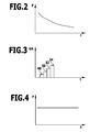
- Figur 2
- eine schematische Darstellung des Verlaufs des Drucks in einem Druckbehälter über die Zeit bei allmählicher Entleerung des Druckbehälters;
- Figur 3
- schematisch den zeitlichen Verlauf der Gesamtnennweite (GN) an einer erfindungsgemäßen Druckminderereinrichtung bei einem Druckverlauf gemäß Figur 2; und
- Figur 4
- schematisch den zeitlichen Verlauf des Gesamtflusses bei entsprechender Ansteuerung der Druckminderereinrichtung.
- FIG. 1
- a schematic representation of an embodiment of a fuel cell system according to the invention;
- FIG. 2
- a schematic representation of the course of the pressure in a pressure vessel over time with gradual emptying of the pressure vessel;
- FIG. 3
- schematically the time course of the total nominal width (GN) at a pressure reducing device according to the invention in a pressure curve according to Figure 2; and
- FIG. 4
- schematically the time course of the total flow with appropriate control of the pressure reducer.
Ein Ausführungsbeispiel eines erfindungsgemäßen Brennstoffzellensystems, welches in Figur 1 schematisch gezeigt und dort mit 10 bezeichnet ist, umfasst (mindestens) einen Brennstoffzellenblock 12 (Brennstoffzellenstapel) mit einer Mehrzahl von Brennstoffzellen 14.An exemplary embodiment of a fuel cell system according to the invention, which is shown schematically in FIG. 1 and designated therein by 10, comprises (at least) one fuel cell block 12 (fuel cell stack) having a plurality of
Die Brennstoffzellen 14 sind beispielsweise Polymermembran-Brennstoffzellen (PEFC), welche eine protonenleitende Folie als Elektrolyt umfassen.The
Den Brennstoffzellen 14 wird Brennstoff und Oxidator zugeführt. Bei Polymermembran-Brennstoffzellen ist der Brennstoff Wasserstoff. Der Oxidator ist reiner Sauerstoff oder Luftsauerstoff.The
An den Brennstoffzellen 14 erfolgt eine katalytische Umsetzung von Brennstoff und Oxidator unter Stromerzeugung. Der erzeugte Strom kann durch einen Verbraucher genutzt werden (in Figur 1 ist der Verbraucher nicht gezeigt).At the
Als Brennstoffspeicher ist ein Druckbehälter 16 vorgesehen, in dem der Brennstoff unter Druck aufgenommen ist. Beispielsweise ist der Brennstoff unter einem Druck von ca. 400 bar oder ca. 700 bar in dem Druckbehälter 16 gespeichert. Insbesondere ist der Druckbehälter 16 als Gasflasche ausgebildet.As fuel storage, a
Der Oxidator ist insbesondere in der Form von reinem Sauerstoff in einem Druckbehälter 18 gespeichert. Der Druckbehälter 18 ist ebenfalls insbesondere als Gasflasche ausgebildet. In ihm ist der Oxidator (vorzugsweise in der Form von reinem Sauerstoff) beispielsweise unter einem Druck von ca. 400 bar oder ca. 700 bar gespeichert.The oxidizer is stored in particular in the form of pure oxygen in a
Dem Brennstoffzellenblock 12 wird der Brennstoff von dem Druckbehälter 16 über eine Leitung 20 zugeführt. Die Leitung 20 mündet in einen Verteiler am Brennstoffzellenblock 12 (in der Zeichnung nicht gezeigt), über den die einzelnen Brennstoffzellen 14 mit Brennstoff versorgt werden. Dem Brennstoffzellenblock 12 wird der Brennstoff unter einem Druck von beispielsweise ca. 2 bar zugeführt. Zur Druckherabsetzung ist eine erste Druckminderereinrichtung 22 vorgesehen, welche dem Druckbehälter 16 nachgeordnet ist. Die Leitung 20 führt von der ersten Druckminderereinrichtung 22 zu dem Brennstoffzellenblock 12. Ferner ist der Druckbehälter 16 an die erste Druckminderereinrichtung 22 angeschlossen.The
Die erste Druckminderereinrichtung 22 weist eine Ventilbank 24 mit einer Mehrzahl von Schaltventilen 26 auf. Die Schaltventile 26 sind Einwegventile, welche im geöffneten Zustand Brennstoff von dem Druckbehälter 16 in die Leitung 20 durchlassen. Die Schaltventile 26 weisen zwei Schaltzustände auf, nämlich offen und geschlossen.The first
Die Ventilbank 24 umfasst mindestens zwei Schaltventile 26 und vorzugsweise mindestens zehn solcher Schaltventile 26. Es können beispielsweise 50 oder mehr Schaltventile 26 vorgesehen sein.The
Die Schaltventile 26 sind als NC-Schaltventile ausgebildet (NC - normally closed), das heißt im stromlosen Zustand sind sie geschlossen und verhindern dadurch ein Austreten von Brennstoff aus dem Druckbehälter 16.The switching
Die Schaltventile 26 sind individuell ansteuerbar. Zur Ansteuerung ist eine Steuerungs- und/oder Regelungseinrichtung 28 vorgesehen, welche über Steuerleitungen an die Schaltventile 26 gekoppelt ist.The switching
An der Leitung 20 ist ein Drucksensor 30 angeordnet, welcher den tatsächlichen Druck misst, mit welchem Brennstoff dem Brennstoffzellenblock 12 zugeführt wird. Der Drucksensor 30 ist über eine Signalleitung 32 mit der Steuerungs- und/oder Regelungseinrichtung 28 verbunden und liefert dieser die entsprechenden Druckmesswerte. Insbesondere lassen sich die Schaltventile 26 durch die Steuerungs- und/oder Regelungseinrichtung 28 gepulst ansteuern, wobei die Pulsfrequenz veränderlich sein kann.On
Die Schaltventile 26 sind beispielsweise als Piezoventile ausgebildet. Sie sind elektrisch ansteuerbar und weisen eine kurze Reaktionszeit auf, die unterhalb von 50 ms und insbesondere unterhalb von 10 ms liegt. Die Schaltventile 26 der Ventilbank 24 sind kleine Mikroventile, welche schnell reagieren und eine individuelle kleine Nennweite aufweisen. Die Gesamtnennweite der ersten Druckminderereinrichtung 22 wird durch entsprechende Ansteuerung der Gesamtzahl der Schaltventile 26 über die Steuerungs- und/oder Regelungseinrichtung 28 angesteuert. Wenn alle Schaltventile 26 geschlossen sind, dann ist die Gesamtnennweite Null. Wenn alle Schaltventile 26 der Ventilbank 24 geöffnet sind, dann ist die Gesamtnennweite die Summe der individuellen Nennweiten aller Schaltventile 26.The switching
Dem Druckbehälter 18 ist eine zweite Druckminderereinrichtung 34 zugeordnet, welche eine Ventilbank 36 mit einer Mehrzahl von Schaltventilen 38 aufweist. Die Schaltventile 38 sind grundsätzlich gleich ausgebildet wie die Schaltventile 26 und die zweite Druckminderereinrichtung 34 ist nach dem gleichen Prinzip ausgebildet wie die erste Druckminderereinrichtung 22. Insbesondere ist der zweiten Druckminderereinrichtung 34 eine Steuerungs- und/oder Regelungseinrichtung 40 zugeordnet, über welche die Schaltventile 38 über entsprechende Signalleitungen individuell ansteuerbar sind.The
Von der zweiten Druckminderereinrichtung 34 führt eine Leitung 42 zu dem Brennstoffzellenblock 12. Diese Leitung 42 steht in Verbindung mit einem Verteiler, über welchen die Brennstoffzellen 14 des Brennstoffzellenblocks 12 mit Oxidator versorgbar sind.From the second
An der Leitung 42 ist ein Drucksensor 44 angeordnet, welcher über eine Signalleitung 46 seine Druckmesswerte der Steuerungs- und/oder Regelungseinrichtung 40 bereitstellt. Über den Drucksensor 44 lässt sich der Oxidatordruck bei der Zuführung zu dem Brennstoffzellenblock 12 ermitteln.On the
Die erste Druckminderereinrichtung 22 und die zweite Druckminderereinrichtung 34 sind als Ventilbänke 24 bzw. 36 mit einer Mehrzahl von Mikroventilen 26, 38 aufgebaut. Diese Mikroventile 26, 38 weisen kleine Nennweiten auf und reagieren schnell. Dadurch lassen sich die Druckminderereinrichtungen 22 und 34 mit relativ geringer Masse ausbilden.The first
Durch die kurzen Reaktionszeiten ist eine Flusssteuerung möglich. Beispielsweise lässt sich eine Proportionalregelung des Brennstoffflusses bzw. Oxidatorflusses zu dem Brennstoffzellenblock 12 realisieren. Weiterhin ist der elektrische Eigenverbrauch der Schaltventile 26, 38 relativ gering.Due to the short reaction times, flow control is possible. For example, a proportional control of the fuel flow or oxidizer flow to the
Das Brennstoffzellensystem 10 umfasst weitere Komponenten wie beispielsweise Kühleinrichtungen, welche in Figur 1 nicht gezeigt sind.The fuel cell system 10 includes other components, such as cooling devices, which are not shown in FIG.
Dem Brennstoffzellenblock 12 wird Brennstoff aus dem Druckbehälter 16 und Oxidator aus dem Druckbehälter 18 bereitgestellt. Durch die erste Druckminderereinrichtung 22 und die zweite Druckminderereinrichtung 34 erfolgt eine Druckherabsetzung, um Brennstoff bzw. Oxidator unter einem geeigneten Druck dem Brennstoffzellenblock 12, bei welchem dieser einen optimierten Wirkungsgrad hat, bereitstellen zu können.The
Der Druck, in welchem der Brennstoff in dem Druckbehälter 16 und der Oxidator in dem Druckbehälter 18 steht, nimmt im Laufe der Zeit aufgrund Entleerung des Druckbehälters 16 bzw. des Druckbehälters 18 ab. Dies ist schematisch in Figur 2 gezeigt.The pressure in which the fuel in the
Durch die erfindungsgemäße Lösung lässt sich über individuelle Ansteuerung der Schaltventile 26 durch die Steuerungs- und/oder Regelungseinrichtung 38 bzw. durch Ansteuerung der Schaltventile 38 über die Steuerungs- und/oder Regelungseinrichtung 40 der notwendige Druck für den Brennstoffzellenblock 12 aufrechterhalten. Dies wird im Folgenden anhand der Brennstoffzuführung erläutert:
- Beispielsweise ist bei hohem
Druck im Druckbehälter 16 nur ein Schaltventil 48 (Figur 3)der Ventilbank 24 geöffnet. Die Gesamtnennweite GN der ersten Druckminderereinrichtung 22 ist dann die Nennweite des ersten Schaltventils 48. Wenn derDruck im Druckbehälter 16 weiter abfällt (Figur 2), dann lässt sich über sukzessive Öffnung eines zweiten Schaltventils 50, eines dritten Schaltventils 52, eines vierten Schaltventils 54 usw. die Gesamtnennweite erhöhen. Diese ist die Summe der Nennweiten aller offenen Schaltventile. Dadurch lässt sich der notwendige Druck, mit welchem der Brennstoff andem Brennstoffblock 12 ansteht, in einem optimierten Bereich einstellen. Es lässt sich dabei ein im Wesentlichen konstanter Fluss F (Figur 4) trotzDruckabfall im Druckbehälter 16 erreichen. Dadurch wird der Brennstoffzellenblock 12 auch beiDruckabfall im Druckbehälter 16 aufgrund dessen Entleerung gleichmäßig mit Brennstoff unter dem erforderlichen Druck versorgt. - Es kann auch vorgesehen sein, dass beim Öffnen (bzw. Schließen) eines Schaltventils 26 dieses gepulst angesteuert wird, um ein "allmähliches Öffnen" durch schnelle Öffnungs- und Schließvorgänge entsprechend der Pulsung zu erreichen. Beispielsweise erfolgt eine Pulsansteuerung mit einer allmählich zunehmenden Frequenz bis
das entsprechende Schaltventil 26 dauerhaft geöffnet ist. Dadurch lässt sich eine Linearisierung der Druckverhältnisse beim Öffnen (bzw. Schließen) eines Schaltventils 26 erreichen, das heißt es werden plötzliche Drucksprünge aufgrund des Öffnens (bzw. Schließens) eines Schaltventils 26 verhindert. - Beispielsweise ist auch eine Flussanpassung möglich, wenn ein Verbraucher, wenn an
den Brennstoffzellenblock 12 angeschlossen ist, eine größere oder kleinere Strommenge verbraucht. Über den Drucksensor 30 wird der Druck inder Leitung 20 gemessen und der Druckwert wird an die Steuerungs- und/oder Regelungseinrichtung 28 weitergegeben. Dadurch lässt sich ein Regelkreis realisieren, wobei über individuelle Ansteuerung der Schaltventile 26 des Ventilblocks 24 die Gesamtnennweite der ersten Druckminderereinrichtung 22 so eingestellt wird, dass beispielsweise der Fluss F (Figur 4) im Wesentlichen konstant bleibt. Dieser im Wesentlichen konstante Fluss lässt sich dabei einstellen, ohne dass ein Flusssensor notwendig ist.- Insbesondere lässt sich die
Ventilbank 24 im Sinne eines Proportionalventils einsetzen. - Durch die
Leitung 20 zwischen der ersten Druckminderereinrichtung 22und dem Brennstoffzellenblock 12 und dem darin befindlichen Brennstoff wird eine Pufferfunktion erzielt, das heißt beim Öffnen bzw.Schließen von Schaltventilen 26der Ventilbank 24 treten keine großen Drucksprünge in derLeitung 20 und damit für die Brennstoffzuführungzu dem Brennstoffzellenblock 12 auf. - Das erfindungsgemäße Brennstoffzellensystem lässt sich vorteilhafterweise in mobilen Anwendungen einsetzen. Durch die erfindungsgemäße Lösung ist die Masse reduziert. (Konventionelle Druckminderereinrichtungen wie beispielsweise einstufige oder zweistufige Membrandruckminderer sind relativ schwer und weisen Massen in der Größenordnung von ca. 1 kg auf.)
- For example, at high pressure in the
pressure vessel 16, only one switching valve 48 (FIG. 3) of thevalve bank 24 is opened. The total nominal width GN of the firstpressure reducing device 22 is then the nominal diameter of thefirst switching valve 48. If the pressure in thepressure vessel 16 continues to drop (FIG. 2), the total nominal width can be increased by successively opening asecond switching valve 50, athird switching valve 52, afourth switching valve 54, etc. This is the sum of the nominal diameters of all open switching valves. As a result, the necessary pressure with which the fuel is present at thefuel block 12 can be set in an optimized range. In this case, a substantially constant flow F (FIG. 4) can be achieved despite a pressure drop in thepressure vessel 16. As a result, thefuel cell block 12 is supplied even with pressure drop in thepressure vessel 16 due to its emptying evenly with fuel at the required pressure. - It may also be provided that, when opening (or closing) a switching
valve 26, it is pulsed in order to achieve a "gradual opening" by rapid opening and closing operations corresponding to the pulsation. For example, a pulse control takes place with a gradually increasing frequency until thecorresponding switching valve 26 is permanently open. As a result, a linearization of the pressure conditions when opening (or closing) a switchingvalve 26 can be achieved, that is to say sudden pressure jumps due to the opening (or closing) of a switchingvalve 26 are prevented. - For example, a flow adjustment is possible when a consumer, when connected to the
fuel cell block 12 consumes a larger or smaller amount of electricity. - Via the
pressure sensor 30, the pressure in theline 20 is measured and the pressure value is passed on to the control and / or regulatingdevice 28. As a result, a control loop can be realized, wherein the total nominal width of the firstpressure reducing device 22 is set by individual control of the switchingvalves 26 of thevalve block 24 so that, for example, the flow F (FIG. 4) remains substantially constant. This essentially constant flow can be adjusted without the need for a flow sensor. - In particular, the
valve bank 24 can be used in the sense of a proportional valve. - Through the
line 20 between thefirst pressure reducer 22 and thefuel cell block 12 and the fuel therein, a buffer function is achieved, that is, when opening or closing of switchingvalves 26 of thevalve bank 24 occur no large pressure jumps in theline 20 and thus for the fuel supply thefuel cell block 12. - The fuel cell system according to the invention can advantageously be used in mobile applications. By the solution according to the invention, the mass is reduced. (Conventional pressure reducers such as single-stage or two-stage diaphragm pressure reducers are relatively heavy and have masses of the order of 1 kg.)
Claims (22)
Applications Claiming Priority (1)
| Application Number | Priority Date | Filing Date | Title |
|---|---|---|---|
| DE102006002512A DE102006002512A1 (en) | 2006-01-16 | 2006-01-16 | A fuel cell system and method for providing fuel and / or oxidizer to a fuel cell stack |
Publications (2)
| Publication Number | Publication Date |
|---|---|
| EP1808925A1 true EP1808925A1 (en) | 2007-07-18 |
| EP1808925B1 EP1808925B1 (en) | 2010-11-03 |
Family
ID=37998331
Family Applications (1)
| Application Number | Title | Priority Date | Filing Date |
|---|---|---|---|
| EP07100522A Not-in-force EP1808925B1 (en) | 2006-01-16 | 2007-01-15 | Pressure reducing device for fuel cell system comprising a plurality of individually controllable switching valves and method therefore |
Country Status (3)
| Country | Link |
|---|---|
| EP (1) | EP1808925B1 (en) |
| AT (1) | ATE487244T1 (en) |
| DE (2) | DE102006002512A1 (en) |
Families Citing this family (1)
| Publication number | Priority date | Publication date | Assignee | Title |
|---|---|---|---|---|
| DE102011108380B4 (en) * | 2011-07-22 | 2016-07-07 | Audi Ag | Device for venting and ventilating a fuel tank |
Citations (5)
| Publication number | Priority date | Publication date | Assignee | Title |
|---|---|---|---|---|
| DE10029468A1 (en) * | 1999-06-23 | 2001-04-12 | Daihatsu Motor Co Ltd | Fuel cell system for producing electrical energy comprises a reforming unit, a fuel cell and a hydrogen separating unit |
| US20040137300A1 (en) * | 2002-11-07 | 2004-07-15 | Randall Gemmen | Piezoelectric axial flow microvalve |
| US20040157097A1 (en) * | 2001-04-20 | 2004-08-12 | Axel Heitzler | Fuel cell system and method for regulating pressure in fuel cell systems |
| FR2857632A1 (en) * | 2003-07-18 | 2005-01-21 | Gie Psa Peugeot Citroen | Motor vehicle fuel cell has fuel system comprising air-pressure reducing valve that is disposed near storage unit for preventing system from being exposed to high pressure gas and compresses gas to low pressure |
| US20050016605A1 (en) * | 1999-07-30 | 2005-01-27 | Sherman Faiz Feisal | Microvalve for controlling fluid flow |
Family Cites Families (2)
| Publication number | Priority date | Publication date | Assignee | Title |
|---|---|---|---|---|
| FR2829435B1 (en) * | 2001-09-10 | 2003-11-07 | Peugeot Citroen Automobiles Sa | MOTOR VEHICLE COMPRISING A FUEL CELL AND MEANS FOR EXHAUSTING HYDROGEN GASES |
| DE112004002487D2 (en) * | 2003-10-13 | 2006-08-24 | P21 Power For The 21St Century | The fuel cell system |
-
2006
- 2006-01-16 DE DE102006002512A patent/DE102006002512A1/en not_active Ceased
-
2007
- 2007-01-15 AT AT07100522T patent/ATE487244T1/en active
- 2007-01-15 DE DE502007005508T patent/DE502007005508D1/en active Active
- 2007-01-15 EP EP07100522A patent/EP1808925B1/en not_active Not-in-force
Patent Citations (5)
| Publication number | Priority date | Publication date | Assignee | Title |
|---|---|---|---|---|
| DE10029468A1 (en) * | 1999-06-23 | 2001-04-12 | Daihatsu Motor Co Ltd | Fuel cell system for producing electrical energy comprises a reforming unit, a fuel cell and a hydrogen separating unit |
| US20050016605A1 (en) * | 1999-07-30 | 2005-01-27 | Sherman Faiz Feisal | Microvalve for controlling fluid flow |
| US20040157097A1 (en) * | 2001-04-20 | 2004-08-12 | Axel Heitzler | Fuel cell system and method for regulating pressure in fuel cell systems |
| US20040137300A1 (en) * | 2002-11-07 | 2004-07-15 | Randall Gemmen | Piezoelectric axial flow microvalve |
| FR2857632A1 (en) * | 2003-07-18 | 2005-01-21 | Gie Psa Peugeot Citroen | Motor vehicle fuel cell has fuel system comprising air-pressure reducing valve that is disposed near storage unit for preventing system from being exposed to high pressure gas and compresses gas to low pressure |
Also Published As
| Publication number | Publication date |
|---|---|
| DE102006002512A1 (en) | 2007-07-26 |
| EP1808925B1 (en) | 2010-11-03 |
| DE502007005508D1 (en) | 2010-12-16 |
| ATE487244T1 (en) | 2010-11-15 |
Similar Documents
| Publication | Publication Date | Title |
|---|---|---|
| DE102006019077B4 (en) | Method for controlling the electrical power generation in a fuel cell system | |
| DE102005042772A1 (en) | Fuel cell system and method for its shutdown | |
| EP2283900B1 (en) | Emergency oxygen supply device | |
| EP2385291A1 (en) | Assembly of pulse-modulated quick-switching valves, tank system, method for producing a requested mass flow and use of a tank system | |
| EP3156651B1 (en) | Pressure increasing device | |
| DE112007002775B4 (en) | Fuel cell system | |
| WO2007110349A1 (en) | Fuel cell assembly | |
| EP1897164B1 (en) | Method for supplying a feed gas to a gas chamber of a fuel cell and fuel cell | |
| EP2521210B1 (en) | Method for operating a reformer fuel cell assembly | |
| EP1808925B1 (en) | Pressure reducing device for fuel cell system comprising a plurality of individually controllable switching valves and method therefore | |
| DE3420674C2 (en) | Pressure supply device for a hydraulic system | |
| WO2011015281A1 (en) | Supply assembly for a fuel cell pack, fuel cell module, and method for operating the fuel cell module | |
| CH621855A5 (en) | Method for regulating turbo-compressors | |
| EP1373706B1 (en) | Injection valve | |
| DE3246601A1 (en) | Method for controlling the tyre pressure and tyre pressure control system | |
| DE10200058A1 (en) | Delivery of gaseous fuel to a fuel cell using a simple mechanical regulator valve | |
| WO2002033763A2 (en) | Device for supplying an operating gas to a fuel cell arrangement | |
| WO2019137924A1 (en) | Fuel cell arrangement having differential pressure control for an h2/o2 fuel cell | |
| DE10119339B4 (en) | Fuel cell system and method for pressure regulation in fuel cell systems and use of the fuel cell system | |
| EP1936726B1 (en) | Fuel cell assembly and method for operating a fuel cell | |
| DE10015654A1 (en) | Fuel cell system and method for operating a fuel cell system | |
| DE4292022C2 (en) | Control system for tapping steam from and / or injecting into a turbine | |
| DE10258496B4 (en) | Method for regulating the fuel supply to a fuel cell system | |
| DE102007048317A1 (en) | Method for operating a fuel cell system | |
| EP3619062B1 (en) | Method for operating a pressure-regulating system in a vehicle and pressure-regulating system |
Legal Events
| Date | Code | Title | Description |
|---|---|---|---|
| PUAI | Public reference made under article 153(3) epc to a published international application that has entered the european phase |
Free format text: ORIGINAL CODE: 0009012 |
|
| AK | Designated contracting states |
Kind code of ref document: A1 Designated state(s): AT BE BG CH CY CZ DE DK EE ES FI FR GB GR HU IE IS IT LI LT LU LV MC NL PL PT RO SE SI SK TR |
|
| AX | Request for extension of the european patent |
Extension state: AL BA HR MK YU |
|
| 17P | Request for examination filed |
Effective date: 20080112 |
|
| 17Q | First examination report despatched |
Effective date: 20080221 |
|
| AKX | Designation fees paid |
Designated state(s): AT BE BG CH CY CZ DE DK EE ES FI FR GB GR HU IE IS IT LI LT LU LV MC NL PL PT RO SE SI SK TR |
|
| GRAP | Despatch of communication of intention to grant a patent |
Free format text: ORIGINAL CODE: EPIDOSNIGR1 |
|
| GRAS | Grant fee paid |
Free format text: ORIGINAL CODE: EPIDOSNIGR3 |
|
| GRAA | (expected) grant |
Free format text: ORIGINAL CODE: 0009210 |
|
| AK | Designated contracting states |
Kind code of ref document: B1 Designated state(s): AT BE BG CH CY CZ DE DK EE ES FI FR GB GR HU IE IS IT LI LT LU LV MC NL PL PT RO SE SI SK TR |
|
| REG | Reference to a national code |
Ref country code: GB Ref legal event code: FG4D Free format text: NOT ENGLISH |
|
| REG | Reference to a national code |
Ref country code: CH Ref legal event code: EP |
|
| REG | Reference to a national code |
Ref country code: IE Ref legal event code: FG4D Free format text: LANGUAGE OF EP DOCUMENT: GERMAN |
|
| REF | Corresponds to: |
Ref document number: 502007005508 Country of ref document: DE Date of ref document: 20101216 Kind code of ref document: P |
|
| REG | Reference to a national code |
Ref country code: NL Ref legal event code: VDEP Effective date: 20101103 |
|
| LTIE | Lt: invalidation of european patent or patent extension |
Effective date: 20101103 |
|
| PG25 | Lapsed in a contracting state [announced via postgrant information from national office to epo] |
Ref country code: LT Free format text: LAPSE BECAUSE OF FAILURE TO SUBMIT A TRANSLATION OF THE DESCRIPTION OR TO PAY THE FEE WITHIN THE PRESCRIBED TIME-LIMIT Effective date: 20101103 |
|
| REG | Reference to a national code |
Ref country code: IE Ref legal event code: FD4D |
|
| PG25 | Lapsed in a contracting state [announced via postgrant information from national office to epo] |
Ref country code: BG Free format text: LAPSE BECAUSE OF FAILURE TO SUBMIT A TRANSLATION OF THE DESCRIPTION OR TO PAY THE FEE WITHIN THE PRESCRIBED TIME-LIMIT Effective date: 20110203 Ref country code: LV Free format text: LAPSE BECAUSE OF FAILURE TO SUBMIT A TRANSLATION OF THE DESCRIPTION OR TO PAY THE FEE WITHIN THE PRESCRIBED TIME-LIMIT Effective date: 20101103 Ref country code: IS Free format text: LAPSE BECAUSE OF FAILURE TO SUBMIT A TRANSLATION OF THE DESCRIPTION OR TO PAY THE FEE WITHIN THE PRESCRIBED TIME-LIMIT Effective date: 20110303 Ref country code: SI Free format text: LAPSE BECAUSE OF FAILURE TO SUBMIT A TRANSLATION OF THE DESCRIPTION OR TO PAY THE FEE WITHIN THE PRESCRIBED TIME-LIMIT Effective date: 20101103 Ref country code: SE Free format text: LAPSE BECAUSE OF FAILURE TO SUBMIT A TRANSLATION OF THE DESCRIPTION OR TO PAY THE FEE WITHIN THE PRESCRIBED TIME-LIMIT Effective date: 20101103 Ref country code: FI Free format text: LAPSE BECAUSE OF FAILURE TO SUBMIT A TRANSLATION OF THE DESCRIPTION OR TO PAY THE FEE WITHIN THE PRESCRIBED TIME-LIMIT Effective date: 20101103 Ref country code: NL Free format text: LAPSE BECAUSE OF FAILURE TO SUBMIT A TRANSLATION OF THE DESCRIPTION OR TO PAY THE FEE WITHIN THE PRESCRIBED TIME-LIMIT Effective date: 20101103 Ref country code: PT Free format text: LAPSE BECAUSE OF FAILURE TO SUBMIT A TRANSLATION OF THE DESCRIPTION OR TO PAY THE FEE WITHIN THE PRESCRIBED TIME-LIMIT Effective date: 20110303 |
|
| PG25 | Lapsed in a contracting state [announced via postgrant information from national office to epo] |
Ref country code: GR Free format text: LAPSE BECAUSE OF FAILURE TO SUBMIT A TRANSLATION OF THE DESCRIPTION OR TO PAY THE FEE WITHIN THE PRESCRIBED TIME-LIMIT Effective date: 20110204 |
|
| PG25 | Lapsed in a contracting state [announced via postgrant information from national office to epo] |
Ref country code: IE Free format text: LAPSE BECAUSE OF FAILURE TO SUBMIT A TRANSLATION OF THE DESCRIPTION OR TO PAY THE FEE WITHIN THE PRESCRIBED TIME-LIMIT Effective date: 20101103 Ref country code: ES Free format text: LAPSE BECAUSE OF FAILURE TO SUBMIT A TRANSLATION OF THE DESCRIPTION OR TO PAY THE FEE WITHIN THE PRESCRIBED TIME-LIMIT Effective date: 20110214 Ref country code: CZ Free format text: LAPSE BECAUSE OF FAILURE TO SUBMIT A TRANSLATION OF THE DESCRIPTION OR TO PAY THE FEE WITHIN THE PRESCRIBED TIME-LIMIT Effective date: 20101103 Ref country code: EE Free format text: LAPSE BECAUSE OF FAILURE TO SUBMIT A TRANSLATION OF THE DESCRIPTION OR TO PAY THE FEE WITHIN THE PRESCRIBED TIME-LIMIT Effective date: 20101103 |
|
| BERE | Be: lapsed |
Owner name: DEUTSCHES ZENTRUM FUR LUFT- UND RAUMFAHRT E.V. Effective date: 20110131 |
|
| PG25 | Lapsed in a contracting state [announced via postgrant information from national office to epo] |
Ref country code: SK Free format text: LAPSE BECAUSE OF FAILURE TO SUBMIT A TRANSLATION OF THE DESCRIPTION OR TO PAY THE FEE WITHIN THE PRESCRIBED TIME-LIMIT Effective date: 20101103 Ref country code: MC Free format text: LAPSE BECAUSE OF NON-PAYMENT OF DUE FEES Effective date: 20110131 Ref country code: RO Free format text: LAPSE BECAUSE OF FAILURE TO SUBMIT A TRANSLATION OF THE DESCRIPTION OR TO PAY THE FEE WITHIN THE PRESCRIBED TIME-LIMIT Effective date: 20101103 Ref country code: PL Free format text: LAPSE BECAUSE OF FAILURE TO SUBMIT A TRANSLATION OF THE DESCRIPTION OR TO PAY THE FEE WITHIN THE PRESCRIBED TIME-LIMIT Effective date: 20101103 Ref country code: DK Free format text: LAPSE BECAUSE OF FAILURE TO SUBMIT A TRANSLATION OF THE DESCRIPTION OR TO PAY THE FEE WITHIN THE PRESCRIBED TIME-LIMIT Effective date: 20101103 |
|
| REG | Reference to a national code |
Ref country code: CH Ref legal event code: PL |
|
| PLBE | No opposition filed within time limit |
Free format text: ORIGINAL CODE: 0009261 |
|
| STAA | Information on the status of an ep patent application or granted ep patent |
Free format text: STATUS: NO OPPOSITION FILED WITHIN TIME LIMIT |
|
| 26N | No opposition filed |
Effective date: 20110804 |
|
| REG | Reference to a national code |
Ref country code: FR Ref legal event code: ST Effective date: 20110930 |
|
| GBPC | Gb: european patent ceased through non-payment of renewal fee |
Effective date: 20110203 |
|
| PG25 | Lapsed in a contracting state [announced via postgrant information from national office to epo] |
Ref country code: FR Free format text: LAPSE BECAUSE OF NON-PAYMENT OF DUE FEES Effective date: 20110131 Ref country code: CH Free format text: LAPSE BECAUSE OF NON-PAYMENT OF DUE FEES Effective date: 20110131 Ref country code: LI Free format text: LAPSE BECAUSE OF NON-PAYMENT OF DUE FEES Effective date: 20110131 |
|
| PG25 | Lapsed in a contracting state [announced via postgrant information from national office to epo] |
Ref country code: BE Free format text: LAPSE BECAUSE OF NON-PAYMENT OF DUE FEES Effective date: 20110131 |
|
| REG | Reference to a national code |
Ref country code: DE Ref legal event code: R097 Ref document number: 502007005508 Country of ref document: DE Effective date: 20110804 |
|
| PG25 | Lapsed in a contracting state [announced via postgrant information from national office to epo] |
Ref country code: IT Free format text: LAPSE BECAUSE OF FAILURE TO SUBMIT A TRANSLATION OF THE DESCRIPTION OR TO PAY THE FEE WITHIN THE PRESCRIBED TIME-LIMIT Effective date: 20101103 |
|
| PG25 | Lapsed in a contracting state [announced via postgrant information from national office to epo] |
Ref country code: GB Free format text: LAPSE BECAUSE OF NON-PAYMENT OF DUE FEES Effective date: 20110203 |
|
| REG | Reference to a national code |
Ref country code: AT Ref legal event code: MM01 Ref document number: 487244 Country of ref document: AT Kind code of ref document: T Effective date: 20120115 |
|
| PG25 | Lapsed in a contracting state [announced via postgrant information from national office to epo] |
Ref country code: CY Free format text: LAPSE BECAUSE OF FAILURE TO SUBMIT A TRANSLATION OF THE DESCRIPTION OR TO PAY THE FEE WITHIN THE PRESCRIBED TIME-LIMIT Effective date: 20101103 Ref country code: LU Free format text: LAPSE BECAUSE OF NON-PAYMENT OF DUE FEES Effective date: 20110115 |
|
| PG25 | Lapsed in a contracting state [announced via postgrant information from national office to epo] |
Ref country code: AT Free format text: LAPSE BECAUSE OF NON-PAYMENT OF DUE FEES Effective date: 20120115 |
|
| PG25 | Lapsed in a contracting state [announced via postgrant information from national office to epo] |
Ref country code: TR Free format text: LAPSE BECAUSE OF FAILURE TO SUBMIT A TRANSLATION OF THE DESCRIPTION OR TO PAY THE FEE WITHIN THE PRESCRIBED TIME-LIMIT Effective date: 20101103 |
|
| PG25 | Lapsed in a contracting state [announced via postgrant information from national office to epo] |
Ref country code: HU Free format text: LAPSE BECAUSE OF FAILURE TO SUBMIT A TRANSLATION OF THE DESCRIPTION OR TO PAY THE FEE WITHIN THE PRESCRIBED TIME-LIMIT Effective date: 20101103 |
|
| REG | Reference to a national code |
Ref country code: DE Ref legal event code: R082 Ref document number: 502007005508 Country of ref document: DE Representative=s name: HOEGER, STELLRECHT & PARTNER PATENTANWAELTE MB, DE |
|
| PGFP | Annual fee paid to national office [announced via postgrant information from national office to epo] |
Ref country code: DE Payment date: 20181219 Year of fee payment: 13 |
|
| REG | Reference to a national code |
Ref country code: DE Ref legal event code: R082 Ref document number: 502007005508 Country of ref document: DE Representative=s name: HOEGER, STELLRECHT & PARTNER PATENTANWAELTE MB, DE |
|
| REG | Reference to a national code |
Ref country code: DE Ref legal event code: R119 Ref document number: 502007005508 Country of ref document: DE |
|
| PG25 | Lapsed in a contracting state [announced via postgrant information from national office to epo] |
Ref country code: DE Free format text: LAPSE BECAUSE OF NON-PAYMENT OF DUE FEES Effective date: 20200801 |