EP1810603A1 - Suction head for a vacuum cleaner - Google Patents
Suction head for a vacuum cleaner Download PDFInfo
- Publication number
- EP1810603A1 EP1810603A1 EP06253907A EP06253907A EP1810603A1 EP 1810603 A1 EP1810603 A1 EP 1810603A1 EP 06253907 A EP06253907 A EP 06253907A EP 06253907 A EP06253907 A EP 06253907A EP 1810603 A1 EP1810603 A1 EP 1810603A1
- Authority
- EP
- European Patent Office
- Prior art keywords
- suction head
- arms
- region
- barriers
- diverge
- Prior art date
- Legal status (The legal status is an assumption and is not a legal conclusion. Google has not performed a legal analysis and makes no representation as to the accuracy of the status listed.)
- Granted
Links
Images

Classifications
-
- A—HUMAN NECESSITIES
- A47—FURNITURE; DOMESTIC ARTICLES OR APPLIANCES; COFFEE MILLS; SPICE MILLS; SUCTION CLEANERS IN GENERAL
- A47L—DOMESTIC WASHING OR CLEANING; SUCTION CLEANERS IN GENERAL
- A47L5/00—Structural features of suction cleaners
- A47L5/12—Structural features of suction cleaners with power-driven air-pumps or air-compressors, e.g. driven by motor vehicle engine vacuum
- A47L5/22—Structural features of suction cleaners with power-driven air-pumps or air-compressors, e.g. driven by motor vehicle engine vacuum with rotary fans
- A47L5/28—Suction cleaners with handles and nozzles fixed on the casings, e.g. wheeled suction cleaners with steering handle
-
- A—HUMAN NECESSITIES
- A47—FURNITURE; DOMESTIC ARTICLES OR APPLIANCES; COFFEE MILLS; SPICE MILLS; SUCTION CLEANERS IN GENERAL
- A47L—DOMESTIC WASHING OR CLEANING; SUCTION CLEANERS IN GENERAL
- A47L9/00—Details or accessories of suction cleaners, e.g. mechanical means for controlling the suction or for effecting pulsating action; Storing devices specially adapted to suction cleaners or parts thereof; Carrying-vehicles specially adapted for suction cleaners
- A47L9/02—Nozzles
Definitions
- This invention relates to a suction head for a vacuum cleaner.
- Suction heads for vacuum cleaners are conventionally rectangular in shape, having reasonable width with relatively shallow depth.
- a problem associated with such conventional suction heads is that they do not function well with larger particles of debris. Small particles of debris pass readily beneath the leading edge of the suction head, but larger particles do not.
- suction heads for vacuum cleaners are known. They become significantly less effective when a debris collection bag is almost full or a filter becomes blocked, thus reducing the airflow through the suction head.
- most suction heads will cope adequately with most debris except for the largest items, but as the airflow reduces conventional suction heads fail to pick up denser items of debris such as small stones and particles of debris within crevices in the surface being cleaned.
- a suction head for a vacuum cleaner comprising:
- a substantially continuous further ground-engaging barrier may extend along the region of an outer edge of the arms substantially from the free end of one of the arms to the free end of the other of the arms.
- a first substantially continuous further ground-engaging barrier may extend along the region of an outer edge of one of the arms substantially from the free end of the arm to the region of the body from which the arms diverge and a second substantially continuous further ground-engaging barrier may extend along the region of an outer edge of the other of the arms substantially from the free end of the arm to the region of the body from which the arms diverge, there being a further gap between the first and second further barriers in the region of the body from which the arms diverge for the passage of relatively large particles of debris into the suction head.
- the channel formed in each of the arms may be open at the free end of each arm.
- the arms may diverge in a V-shape or a U-shape.
- the body may be provided with one or more wheels for supporting the body relative to the ground.
- One wheel may be provided each side of the outlet opening.
- the suction head may include an outlet connection including a first tubular member secured to or formed integrally with the body and a second tubular member rotatable about the axis thereof relative to the first tubular member.
- the axis of the second tubular member may incorporate an angle along the length thereof.
- Rotatable means may be provided substantially at the free end of each arm for engaging with obstacles.
- the rotatable means may be in the form of a roller which is rotatable about a substantially upright axis.
- the cross-sectional area of the channel may decrease towards the free end of each arm.
- the barriers may be flexible, for example resilient.
- One or more of the barriers may comprise a plurality of stiff resilient bristles.
- one or more of the barriers may comprise a continuous strip.
- the continuous strip may be elastomeric, such as of rubber.
- the barrier or barriers in the region of the outer edge of the arms may comprise a plurality of stiff resilient bristles, while the barriers in the region of the inner edge of the arms may each comprise a continuous strip.
- the present invention provides a suction head for vacuum cleaners which works particularly effectively, for example on hard surfaces, even under conditions of reduced airflow such as often occur when a debris collection bag is almost full or a filter becomes blocked, or in the case of a cordless suction cleaner which is powered by batteries and consequently has a lower airflow compared with mains powered cleaners.
- the present invention also relates to a vacuum cleaner incorporating a suction head as hereinbefore defined.
- the suction head of the vacuum cleaner may be provided with a handle for propelling the suction head by hand.
- the suction head will generally be provided with suction-generating means, debris collecting means and optionally with a battery, such as a rechargeable battery.
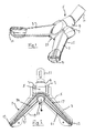
- the vacuum cleaner suction head shown in the drawings includes a generally hollow domed body having two arms 1, 3 which diverge towards their free ends and are therefore arranged substantially in the shape of a V. That is, in contrast to conventional suction heads, the arms 1, 3 diverge at an angle less than 180 degrees.
- each arm 1, 3 is generally in the form of an inverted U, although it will be appreciated that modifications of this shape can be employed.
- the suction head is provided with an outlet 5 for connection to a vacuum (suction) cleaner (not shown) and with a pair of freely rotatable wheels 7 for supporting the suction head, at least in part, during use.
- the wheels 7 are conveniently mounted one to each side of the outlet.
- the outlet 5 has an opening 6 into the interior of the suction head.
- the outlet itself is conveniently formed in two parts, a first part 9 which is secured to or formed integrally with the body of the suction head and a second part 11 which is rotatable relative to the first part about a longitudinal axis thereof.
- the second part 11 incorporates an angle in the longitudinal axis thereof such that rotation of the second part about its axis causes lateral movement in the suction head which can be used to steer the suction head.
- the outlet is connected to the remainder of the body of the suction head in a generally downwardly inclined direction.
- the arms 1, 3 are provided at their free ends with rollers 13.
- the rollers are mounted so as to be freely rotatable about an upright axis and extend a short distance beyond the end of the respective arm so as to engage against a surface such as a wall, skirting or the like so as to roll along the surface without causing damage.
- the cross-sectional area of the free space within the arms 1, 3 decreases progressively towards the free ends of the arms.
- This arrangement provides a relatively narrow channel 14, which is open at the free ends of the arms, for the passage of air and debris along each arm 1, 3 and allows the air speed within the channels to remain relatively constant along the length of the arms despite the fact that additional air continually enters as the flow path approaches the outlet 5.
- the channel 14 is particularly useful for removing particles of debris from crevices beneath the suction head and for cleaning adjacent to obstacles such as walls and items of furniture.
- the region of the trailing (or outer) edge 15 of the body is provided with a continuous flexible (resilient) barrier 17 which extends from the free end of one of the arms, past the region of the outlet, to the free end of the other of the arms.
- the barrier engages with the ground as represented by a surface to be cleaned and is formed of a plurality of stiff resilient bristles which may allow the passage of a small amount of air therethrough, but substantially prevent the loss of any particles of debris. Bristles have the advantage that they can dislodge small particles of debris from within crevices beneath the suction head.
- the barrier 15 may be formed from a continuous strip of resilient material, for example an elastomeric material such as rubber.
- the region of the leading (inner) edge 19 of the body is provided with two separate continuous flexible (resilient) barriers 21.
- Each barrier 21 extends from the free end of the respective arm towards the region of the outlet, but the barriers 21 are of a length such that there is a gap 23 between the ends of the barriers 21 in the region of the outlet 5 for the passage of larger particles of debris.
- the barriers 21 engage with the ground as represented by the surface to be cleaned and are each formed from a continuous strip of resilient material, for example an elastomeric material such as rubber.
- the continuous strip offers the advantage that it prevents the passage of undesired air through the barrier and into the channel 14, which could have the effect of reducing the overall speed of air within the channel 14.
- the barriers 21 may be formed from a plurality of resilient bristles which may allow the passage of a small amount of air therethrough.
- the arrangement in the region of the trailing (or outer) edge can be similar to that in the region of the leading (or inner) edge in that two separate barriers may be provided with a gap between the barrier for the passage of larger particles of debris. In this way such larger particles of debris can be collected irrespective of whether the suction head is moving forwardly or rearwardly.
- the arms 1 and 3 of the body of the suction head do not necessarily have to be arranged in the shape of a V.
- the arms could be arranged in the shape of a U, or in any other configuration in which the two arms generally diverge so as, in use, to cause larger particles of debris to roll towards the region where the two arms join in order that such larger particles of debris can be drawn into the suction head through a single aperture in the leading edge of the suction head.
- the arms may be incorporated into the body of the suction head.
- the arms may be formed on a lower face of the body. Such an arrangement would still allow larger particles of debris to roll or be urged towards the gap 23, but the debris may not be visible to the user unless, for example, the body is made of a transparent of translucent material.
- the vacuum cleaner may be mains powered or may be cordless, for example powered by rechargeable batteries.
- the suction head is first connected to a vacuum cleaner (not shown) by way of a conventional elongate tubular handle and the vacuum cleaner is switched on so as to create a flow of air through the outlet 5 towards the vacuum cleaner itself.
- the handle of the vacuum cleaner can be used to move the suction head forwards and backwards and can additionally be twisted about its axis to rotate the head to the left or to the right.
- the combination of forwards and backwards movement, together with rotation of the suction head allows the suction head to be steered with reasonable accuracy, for example to direct the head towards larger particles of debris.
- rollers 13 at the free ends of the arms 1, 3 assist in regions where there are obstacles such as walls or pieces of furniture inasmuch as the rollers 13 can be urged against an obstacle to cause the suction head to turn and be steered.
- the rollers substantially prevent any damage to the obstacle itself because there is no need for sliding motion to occur between the rollers and the obstacle.
- the suction head according to the present invention works particularly effectively when cleaning hard floors, even under conditions of reduced airflow such as often occur when a debris collection bag is almost full or a filter becomes blocked.
- the efficient use of airflow due to the barriers 17 and 21 results in the suction head being particularly effective with cordless, that is battery powered, appliances.
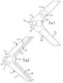
- the suction head shown in Figures 5 and 6 is provided integrally therewith with a battery 25, suction means 27 and debris collection means 29, together with a handle 31 for propelling and steering the suction head.
- Figures 5 and 6 do not show rollers 13, such rollers may be provided if desired.
- the arrangement shown in Figures 5 and 6 provides a compact and efficient hand-operated vacuum cleaner.
Abstract
Description
- This invention relates to a suction head for a vacuum cleaner.
- Suction heads for vacuum cleaners are conventionally rectangular in shape, having reasonable width with relatively shallow depth. A problem associated with such conventional suction heads is that they do not function well with larger particles of debris. Small particles of debris pass readily beneath the leading edge of the suction head, but larger particles do not. It is known to provide gaps, or castellations, along the length of the leading edge in order that larger particles of debris can pass through the gaps, but such gaps lead to a reduction in efficiency of the vacuum cleaner with the result that the cleaner does not pick up debris effectively, particularly relatively large and heavy particles of debris. It has proved to be especially difficult to balance the need for gaps in order to pick up large and heavy particles of debris with the need to keep the size of the gaps to a minimum in order to maintain the suction efficiency.
- A further problem that arises with known suction heads for vacuum cleaners is that is that they become significantly less effective when a debris collection bag is almost full or a filter becomes blocked, thus reducing the airflow through the suction head. When the airflow is high, most suction heads will cope adequately with most debris except for the largest items, but as the airflow reduces conventional suction heads fail to pick up denser items of debris such as small stones and particles of debris within crevices in the surface being cleaned.
- It is therefore an object of the present invention to provide a vacuum head for a suction cleaner which overcomes or at least ameliorates the above disadvantages.
- According to the present invention there is provided a suction head for a vacuum cleaner, the suction head comprising:
- a substantially hollow body including a pair of arms which diverge from a predetermined region of the body at an angle less than 180 degrees relative to each other, each arm defining therein a channel for the passage of air, which channel extends substantially from the free end of the arm to the region of the body from which the arms diverge;
- an outlet opening located in the region of the body from which the arms diverge for the passage of air to a vacuum cleaner;
- a first substantially continuous ground-engaging barrier extending along the region of an inner edge of one of the arms substantially from the free end of the arm to the region of the body from which the arms diverge; and
- a second substantially continuous ground-engaging barrier extending along the region of an inner edge of the other of the arms substantially from the free end of the arm to the region of the body from which the arms diverge, there being a gap between the first and second barriers in the region of the body from which the arms diverge for the passage of relatively large particles of debris into the suction head, the first and second barriers being adapted to engage a substantially flat ground surface along the entire length of the first and second barriers.
- A substantially continuous further ground-engaging barrier may extend along the region of an outer edge of the arms substantially from the free end of one of the arms to the free end of the other of the arms.
- Alternatively, a first substantially continuous further ground-engaging barrier may extend along the region of an outer edge of one of the arms substantially from the free end of the arm to the region of the body from which the arms diverge and a second substantially continuous further ground-engaging barrier may extend along the region of an outer edge of the other of the arms substantially from the free end of the arm to the region of the body from which the arms diverge, there being a further gap between the first and second further barriers in the region of the body from which the arms diverge for the passage of relatively large particles of debris into the suction head.
- The channel formed in each of the arms may be open at the free end of each arm.
- The arms may diverge in a V-shape or a U-shape.
- The body may be provided with one or more wheels for supporting the body relative to the ground. One wheel may be provided each side of the outlet opening.
- The suction head may include an outlet connection including a first tubular member secured to or formed integrally with the body and a second tubular member rotatable about the axis thereof relative to the first tubular member. The axis of the second tubular member may incorporate an angle along the length thereof. Such an arrangement facilitates steering of the suction head so as to guide large particles of debris towards the gap between the first and second barriers.
- Rotatable means may be provided substantially at the free end of each arm for engaging with obstacles. The rotatable means may be in the form of a roller which is rotatable about a substantially upright axis.
- The cross-sectional area of the channel may decrease towards the free end of each arm.
- The barriers may be flexible, for example resilient. One or more of the barriers may comprise a plurality of stiff resilient bristles. Alternatively or additionally, one or more of the barriers may comprise a continuous strip. The continuous strip may be elastomeric, such as of rubber. The barrier or barriers in the region of the outer edge of the arms may comprise a plurality of stiff resilient bristles, while the barriers in the region of the inner edge of the arms may each comprise a continuous strip.
- Thus the present invention provides a suction head for vacuum cleaners which works particularly effectively, for example on hard surfaces, even under conditions of reduced airflow such as often occur when a debris collection bag is almost full or a filter becomes blocked, or in the case of a cordless suction cleaner which is powered by batteries and consequently has a lower airflow compared with mains powered cleaners.
- The present invention also relates to a vacuum cleaner incorporating a suction head as hereinbefore defined. The suction head of the vacuum cleaner may be provided with a handle for propelling the suction head by hand. In such a case, the suction head will generally be provided with suction-generating means, debris collecting means and optionally with a battery, such as a rechargeable battery.
- For a better understanding of the present invention and to show more clearly how it may be carried into effect reference will now be made, by way of example, to the accompanying drawings in which:
- Figure 1 is a perspective view from above of one embodiment of a suction head according to the present invention for a vacuum cleaner;
- Figure 2 is a plan view from below of the suction head shown in Figure 1;
- Figure 3 is a front elevational view of the suction head shown in Figure 1;
- Figure 4 is a side elevational view of the suction head shown in Figure 1;
- Figure 5 is a diagrammatic view from above of an embodiment of the suction head shown in Figure 1 incorporating a battery, suction and collection means; and
- Figure 6 is a diagrammatic view from below of the suction head shown in Figure 5.
- The vacuum cleaner suction head shown in the drawings includes a generally hollow domed body having two
arms arms - Because the body of the suction head is hollow, in order to allow for the passage of air and debris drawn into the suction head, the lateral cross-sectional shape of each
arm - In the region where the two
arms outlet 5 for connection to a vacuum (suction) cleaner (not shown) and with a pair of freelyrotatable wheels 7 for supporting the suction head, at least in part, during use. Thewheels 7 are conveniently mounted one to each side of the outlet. Theoutlet 5 has an opening 6 into the interior of the suction head. The outlet itself is conveniently formed in two parts, afirst part 9 which is secured to or formed integrally with the body of the suction head and a second part 11 which is rotatable relative to the first part about a longitudinal axis thereof. The second part 11 incorporates an angle in the longitudinal axis thereof such that rotation of the second part about its axis causes lateral movement in the suction head which can be used to steer the suction head. The outlet is connected to the remainder of the body of the suction head in a generally downwardly inclined direction. - The
arms rollers 13. The rollers are mounted so as to be freely rotatable about an upright axis and extend a short distance beyond the end of the respective arm so as to engage against a surface such as a wall, skirting or the like so as to roll along the surface without causing damage. - The cross-sectional area of the free space within the
arms narrow channel 14, which is open at the free ends of the arms, for the passage of air and debris along eacharm outlet 5. Thechannel 14 is particularly useful for removing particles of debris from crevices beneath the suction head and for cleaning adjacent to obstacles such as walls and items of furniture. - The region of the trailing (or outer)
edge 15 of the body is provided with a continuous flexible (resilient)barrier 17 which extends from the free end of one of the arms, past the region of the outlet, to the free end of the other of the arms. The barrier engages with the ground as represented by a surface to be cleaned and is formed of a plurality of stiff resilient bristles which may allow the passage of a small amount of air therethrough, but substantially prevent the loss of any particles of debris. Bristles have the advantage that they can dislodge small particles of debris from within crevices beneath the suction head. As an alternative, thebarrier 15 may be formed from a continuous strip of resilient material, for example an elastomeric material such as rubber. - The region of the leading (inner)
edge 19 of the body is provided with two separate continuous flexible (resilient)barriers 21. Eachbarrier 21 extends from the free end of the respective arm towards the region of the outlet, but thebarriers 21 are of a length such that there is agap 23 between the ends of thebarriers 21 in the region of theoutlet 5 for the passage of larger particles of debris. Thebarriers 21 engage with the ground as represented by the surface to be cleaned and are each formed from a continuous strip of resilient material, for example an elastomeric material such as rubber. The continuous strip offers the advantage that it prevents the passage of undesired air through the barrier and into thechannel 14, which could have the effect of reducing the overall speed of air within thechannel 14. As an alternative, thebarriers 21 may be formed from a plurality of resilient bristles which may allow the passage of a small amount of air therethrough. - If desired, the arrangement in the region of the trailing (or outer) edge can be similar to that in the region of the leading (or inner) edge in that two separate barriers may be provided with a gap between the barrier for the passage of larger particles of debris. In this way such larger particles of debris can be collected irrespective of whether the suction head is moving forwardly or rearwardly.
- It should be noted that the
arms gap 23, but the debris may not be visible to the user unless, for example, the body is made of a transparent of translucent material. - The vacuum cleaner may be mains powered or may be cordless, for example powered by rechargeable batteries.
- In use of the vacuum cleaner suction head according to the present invention, the suction head is first connected to a vacuum cleaner (not shown) by way of a conventional elongate tubular handle and the vacuum cleaner is switched on so as to create a flow of air through the
outlet 5 towards the vacuum cleaner itself. The handle of the vacuum cleaner can be used to move the suction head forwards and backwards and can additionally be twisted about its axis to rotate the head to the left or to the right. The combination of forwards and backwards movement, together with rotation of the suction head, allows the suction head to be steered with reasonable accuracy, for example to direct the head towards larger particles of debris. Therollers 13 at the free ends of thearms rollers 13 can be urged against an obstacle to cause the suction head to turn and be steered. The rollers substantially prevent any damage to the obstacle itself because there is no need for sliding motion to occur between the rollers and the obstacle. - As the suction head is moved forwardly, small particles of debris pass beneath the
barriers 21 or are drawn out of crevices below the suction head and are drawn by the flow of air, which passes beneath thebarriers 21, along the elongatenarrow channel 14 and through theoutlet 5, and are carried to the vacuum cleaner. Larger particles of debris, which are unable to pass beneath thebarriers 21, are urged or roll along the leadingedge 19 of the suction head towards the region where the twoarms gap 23 between the twobarriers 21 and can pass into the suction head and through the outlet to the vacuum cleaner. The combination ofbarriers central gap 23 providing an opening for larger particles of debris, has been found to provide effective collection of such larger particles of debris while keeping the reduction of airflow due to the gap to a minimum. - It has been found that the suction head according to the present invention works particularly effectively when cleaning hard floors, even under conditions of reduced airflow such as often occur when a debris collection bag is almost full or a filter becomes blocked. The efficient use of airflow due to the
barriers - The suction head shown in Figures 5 and 6 is provided integrally therewith with a
battery 25, suction means 27 and debris collection means 29, together with ahandle 31 for propelling and steering the suction head. Although Figures 5 and 6 do not showrollers 13, such rollers may be provided if desired. The arrangement shown in Figures 5 and 6 provides a compact and efficient hand-operated vacuum cleaner.
Claims (24)
- A suction head for a vacuum cleaner, the suction head comprising:a substantially hollow body including a pair of arms (1, 3) which diverge from a predetermined region of the body at an angle less than 180 degrees relative to each other, each arm defining therein a channel (14) for the passage of air, which channel extends substantially from the free end of the arm to the region of the body from which the arms diverge;an outlet opening (5) located in the region of the body from which the arms diverge for the passage of air to a vacuum cleaner;a first substantially continuous ground-engaging barrier (21) extending along the region of an inner edge (19) of one of the arms (1) substantially from the free end of the arm to the region of the body from which the arms diverge; anda second substantially continuous ground-engaging barrier (21) extending along the region of an inner edge (19) of the other of the arms (3) substantially from the free end of the arm to the region of the body from which the arms diverge, there being a gap (23) between the first and second barriers (21) in the region of the body from which the arms diverge for the passage of relatively large particles of debris into the suction head, the first andsecond barriers (21) being adapted to engage a substantially flat ground surface along the entire length of the first and second barriers.
- A suction head as claimed in claim 1, characterised in that a substantially continuous further ground-engaging barrier (17) extends along the region of an outer edge (15) of the arms (1, 3) substantially from the free end of one of the arms to the free end of the other of the arms.
- A suction head as claimed in claim 1, characterised in that a first substantially continuous further ground-engaging barrier (17) extends along the region of an outer edge (15) of one of the arms (1) substantially from the free end of the arm to the region of the body from which the arms diverge and a second substantially continuous further ground-engaging barrier (17) extends along the region of an outer edge (15) of the other of the arms (3) substantially from the free end of the arm to the region of the body from which the arms diverge, there being a further gap between the first and second further barriers (17) in the region of the body from which the arms diverge for the passage of relatively large particles of debris into the suction head.
- A suction head as claimed in any preceding claim, characterised in that the channel (14) formed in each of the arms (1, 3) is open at the free end of each arm.
- A suction head as claimed in any preceding claim, characterised in that the arms (1, 3) diverge in a V-shape or a U-shape.
- A suction head as claimed in any preceding claim, characterised in that the body is provided with one or more wheels (7) for supporting the body relative to the ground.
- A suction head as claimed in claim 6, characterised in that one wheel (7) is provided each side of the outlet opening (5).
- A suction head as claimed in any preceding claim and including an outlet connection including a first tubular member (9) secured to or formed integrally with the body and a second tubular member (11) rotatable about the axis thereof relative to the first tubular member.
- A suction head as claimed in claim 8, characterised in that the axis of the second tubular member (11) incorporates an angle along the length thereof.
- A suction head as claimed in any preceding claim, characterised in that rotatable means (13) is provided substantially at the free end of each arm (1, 3) for engaging with obstacles.
- A suction head as claimed in claim 10, characterised in that the rotatable means (13) is in the form of a roller which is rotatable about a substantially upright axis.
- A suction head as claimed in any preceding claim, characterised in that the cross-sectional area of the channel (14) decreases towards the free end of each arm (1, 3).
- A suction head as claimed in any preceding claim, characterised in that the barriers (17, 21) are flexible.
- A suction head as claimed in claim 13, characterised in that the barriers (17, 21) are resilient.
- A suction head as claimed in claim 13 or 14, characterised in that one or more of the barriers (17, 21) comprises a plurality of stiff resilient bristles.
- A suction head as claimed in claim 13, 14 or 15, characterised in that one or more of the barriers (17, 21) comprises a continuous strip.
- A suction head as claimed in claim 16, characterised in that the continuous strip is elastomeric.
- A suction head as claimed in claim 17, characterised in that the continuous strip is made of rubber.
- A suction head as claimed in any one of claims 13 to 18, characterised in that the barrier or barriers (17) in the region of the outer edge (15) of the arms (1, 3) comprise a plurality of stiff resilient bristles, while the barriers (21) in the region of the inner edge (19) of the arms each comprise a continuous strip.
- A vacuum cleaner incorporating a suction head as claimed in any preceding claim.
- A vacuum cleaner as claimed in claim 20, characterised in that the suction head is provided with a handle for propelling the suction head by hand.
- A vacuum cleaner as claimed in claim 21 and including in the suction head suction-generating means (27) and debris collecting means (29).
- A vacuum cleaner as claimed in claim 22, further including a battery (25) in the suction head.
- A vacuum cleaner as claimed in claim 23, characterised in that the battery (25) is rechargeable.
Applications Claiming Priority (1)
| Application Number | Priority Date | Filing Date | Title |
|---|---|---|---|
| GB0601047A GB2419278B (en) | 2006-01-19 | 2006-01-19 | Suction head for a vacuum cleaner |
Publications (2)
| Publication Number | Publication Date |
|---|---|
| EP1810603A1 true EP1810603A1 (en) | 2007-07-25 |
| EP1810603B1 EP1810603B1 (en) | 2013-09-18 |
Family
ID=36010557
Family Applications (1)
| Application Number | Title | Priority Date | Filing Date |
|---|---|---|---|
| EP06253907.7A Active EP1810603B1 (en) | 2006-01-19 | 2006-07-26 | Suction head for a vacuum cleaner |
Country Status (6)
| Country | Link |
|---|---|
| US (1) | US7802343B2 (en) |
| EP (1) | EP1810603B1 (en) |
| CN (1) | CN101002667B (en) |
| CA (1) | CA2555626C (en) |
| ES (1) | ES2438973T3 (en) |
| GB (1) | GB2419278B (en) |
Families Citing this family (20)
| Publication number | Priority date | Publication date | Assignee | Title |
|---|---|---|---|---|
| US20070113361A1 (en) * | 2005-11-18 | 2007-05-24 | Chad Reese | Surface cleaning apparatus |
| CA2677526C (en) * | 2006-12-12 | 2013-11-26 | G.B.D. Corp. | Convertible surface cleaning apparatus |
| US8621709B2 (en) | 2006-12-12 | 2014-01-07 | G.B.D. Corp. | Multi-strut cleaning head |
| CA2640499A1 (en) * | 2007-09-25 | 2009-03-25 | Roger P. Vanderlinden | A debris-plowing pick-up head for a mobile sweeper |
| GB2486666B (en) | 2010-12-22 | 2012-11-07 | Grey Technology Ltd | Vacuum cleaner |
| WO2012171100A1 (en) * | 2011-06-13 | 2012-12-20 | Roger Vanderlinden | Pick-up head system |
| GB201306512D0 (en) | 2013-04-10 | 2013-05-22 | Grey Technology Ltd | Vacuum cleaner |
| WO2014195711A1 (en) | 2013-06-05 | 2014-12-11 | Grey Technology Limited | Hand-held vacuum cleaner |
| USD733141S1 (en) * | 2014-09-10 | 2015-06-30 | Faro Technologies, Inc. | Laser scanner |
| GB2536064B (en) * | 2015-03-06 | 2017-06-07 | Dyson Technology Ltd | A suction nozzle for a vacuum cleaner |
| GB201603300D0 (en) | 2016-02-25 | 2016-04-13 | Grey Technology Ltd | Suction head for a vacuum cleaner |
| GB201603302D0 (en) | 2016-02-25 | 2016-04-13 | Grey Technology Ltd | Dirt-collection chamber for a vacuum cleaner |
| US9861243B1 (en) | 2016-06-30 | 2018-01-09 | Gregory Caldwell | Flexible light weight vacuum cleaner head |
| GB201616598D0 (en) | 2016-09-30 | 2016-11-16 | Grey Technology Limited | Cleaning head for a vacuum cleaner |
| KR102308483B1 (en) * | 2017-03-13 | 2021-10-06 | 삼성전자주식회사 | Cleaner head and vacuum cleaner having the same |
| CN106889945A (en) * | 2017-03-16 | 2017-06-27 | 马涛 | Cleaner suction nozzle |
| GB201706357D0 (en) | 2017-04-21 | 2017-06-07 | Grey Tech Ltd | Bagged vacuum cleaner |
| CN108166427A (en) * | 2018-01-31 | 2018-06-15 | 江苏天普星环境科技有限公司 | A kind of fast-type sweeper running gear |
| JP6601895B1 (en) * | 2019-02-14 | 2019-11-06 | 芳孝 水谷 | Suction nozzle and vacuum cleaner |
| CN111728529A (en) * | 2020-06-16 | 2020-10-02 | 苏州凯弘橡塑有限公司 | Multifunctional portable sterilization acarus killing device |
Citations (8)
| Publication number | Priority date | Publication date | Assignee | Title |
|---|---|---|---|---|
| GB379436A (en) * | 1931-06-17 | 1932-09-01 | Harold Ellis Queen | Floor tool for vacuum cleaning system |
| US2235226A (en) * | 1939-07-11 | 1941-03-18 | Electrolux Corp | Suction nozzle |
| US2610351A (en) * | 1947-09-03 | 1952-09-16 | Masury Young Company | Squeegee nozzle attachment for vacuum cleaners |
| US5347679A (en) * | 1993-01-07 | 1994-09-20 | Royal Appliance Mfg. Co. | Stick type vacuum cleaner |
| US5509171A (en) * | 1994-12-07 | 1996-04-23 | Zejda; Frantisek | Vacuum cleaner bumper system |
| US5765258A (en) * | 1996-01-11 | 1998-06-16 | Black & Decker Inc. | Vacuum cleaner with all components in floor traveling head |
| US20020133903A1 (en) | 2001-03-20 | 2002-09-26 | Vanderlinden Roger P. | Large area surface cleaning tool |
| EP1488726A1 (en) | 2003-06-20 | 2004-12-22 | Seb S.A. | Suction nozzle for vacuum cleaner |
Family Cites Families (12)
| Publication number | Priority date | Publication date | Assignee | Title |
|---|---|---|---|---|
| US1968974A (en) * | 1932-07-30 | 1934-08-07 | Air Way Electric Appl Corp | Vacuum cleaner floor tool |
| US3371371A (en) * | 1966-01-18 | 1968-03-05 | Steccone Ettore | Pick-up tool assembly |
| SE448417B (en) * | 1979-05-09 | 1987-02-23 | Schmidt Alfred Gmbh | DEVICE RECOVERY |
| GB2224195A (en) * | 1988-10-27 | 1990-05-02 | James Arthur Forrest | Vacuum cleaner nozzle |
| US5502870A (en) * | 1993-12-16 | 1996-04-02 | Ragner; Gary D. | Five-function vacuum cleaner nozzle |
| US5699586A (en) * | 1996-01-11 | 1997-12-23 | Black & Decker Inc. | Vacuum cleaner with improved suction inlet |
| WO2002011595A1 (en) * | 2000-08-01 | 2002-02-14 | Electrodomesticos Taurus, Sl | Head for a dust vacuum cleaner |
| EP1222892B1 (en) * | 2001-01-15 | 2006-04-12 | De' Longhi S.P.A. | Suction nozzle for cleaning apparatus such as vacuum cleaners, electric brushes or similar |
| US6588058B2 (en) * | 2001-03-20 | 2003-07-08 | Roger P. Vanderlinden | Large area surface cleaning tool |
| US6772477B2 (en) * | 2002-02-06 | 2004-08-10 | Royal Appliance Mfg. Co. | Floor nozzle for a vacuum cleaner |
| US7467439B2 (en) * | 2002-12-19 | 2008-12-23 | Koninklijke Philips Electronics N.V. | Suction attachment for a vacuum cleaner |
| KR20050038442A (en) * | 2003-10-22 | 2005-04-27 | 삼성광주전자 주식회사 | Floor nozzle for vacuum cleaner |
-
2006
- 2006-01-19 GB GB0601047A patent/GB2419278B/en not_active Expired - Fee Related
- 2006-07-26 EP EP06253907.7A patent/EP1810603B1/en active Active
- 2006-07-26 ES ES06253907.7T patent/ES2438973T3/en active Active
- 2006-08-04 CA CA2555626A patent/CA2555626C/en not_active Expired - Fee Related
- 2006-08-11 US US11/503,443 patent/US7802343B2/en active Active
- 2006-08-25 CN CN2006101212756A patent/CN101002667B/en active Active
Patent Citations (8)
| Publication number | Priority date | Publication date | Assignee | Title |
|---|---|---|---|---|
| GB379436A (en) * | 1931-06-17 | 1932-09-01 | Harold Ellis Queen | Floor tool for vacuum cleaning system |
| US2235226A (en) * | 1939-07-11 | 1941-03-18 | Electrolux Corp | Suction nozzle |
| US2610351A (en) * | 1947-09-03 | 1952-09-16 | Masury Young Company | Squeegee nozzle attachment for vacuum cleaners |
| US5347679A (en) * | 1993-01-07 | 1994-09-20 | Royal Appliance Mfg. Co. | Stick type vacuum cleaner |
| US5509171A (en) * | 1994-12-07 | 1996-04-23 | Zejda; Frantisek | Vacuum cleaner bumper system |
| US5765258A (en) * | 1996-01-11 | 1998-06-16 | Black & Decker Inc. | Vacuum cleaner with all components in floor traveling head |
| US20020133903A1 (en) | 2001-03-20 | 2002-09-26 | Vanderlinden Roger P. | Large area surface cleaning tool |
| EP1488726A1 (en) | 2003-06-20 | 2004-12-22 | Seb S.A. | Suction nozzle for vacuum cleaner |
Also Published As
| Publication number | Publication date |
|---|---|
| US20070163076A1 (en) | 2007-07-19 |
| EP1810603B1 (en) | 2013-09-18 |
| CN101002667A (en) | 2007-07-25 |
| CA2555626A1 (en) | 2007-07-19 |
| US7802343B2 (en) | 2010-09-28 |
| GB2419278B (en) | 2007-01-10 |
| CA2555626C (en) | 2010-06-01 |
| GB0601047D0 (en) | 2006-03-01 |
| GB2419278A (en) | 2006-04-26 |
| ES2438973T3 (en) | 2014-01-21 |
| CN101002667B (en) | 2010-12-01 |
Similar Documents
| Publication | Publication Date | Title |
|---|---|---|
| CA2555626C (en) | Suction head for a vacuum cleaner | |
| KR100493492B1 (en) | Surface cleaning apparatus | |
| US20130312216A1 (en) | Cleaner head | |
| US7013521B2 (en) | Surface cleaning apparatus | |
| EP1475029B1 (en) | Surface cleaning apparatus | |
| AU2005325504B2 (en) | Cleaner head for a cleaning appliance | |
| CA2562943A1 (en) | Surface cleaning apparatus | |
| CN108289581B (en) | Suction head for vacuum cleaner and operation method thereof | |
| US8214960B1 (en) | Floor sweeper | |
| EP3574816B1 (en) | Brush assembly for a floor cleaning apparatus | |
| KR20220057554A (en) | Robot vacuum cleaners and methods of robot vacuum cleaners | |
| US20210307572A1 (en) | Battery powered vacuum cleaner | |
| AU2004201519B2 (en) | Surface cleaning apparatus | |
| WO2013009277A1 (en) | A floor sweeper | |
| JP2015070948A (en) | Suction head and vacuum cleaner |
Legal Events
| Date | Code | Title | Description |
|---|---|---|---|
| PUAI | Public reference made under article 153(3) epc to a published international application that has entered the european phase |
Free format text: ORIGINAL CODE: 0009012 |
|
| AK | Designated contracting states |
Kind code of ref document: A1 Designated state(s): AT BE BG CH CY CZ DE DK EE ES FI FR GB GR HU IE IS IT LI LT LU LV MC NL PL PT RO SE SI SK TR |
|
| AX | Request for extension of the european patent |
Extension state: AL BA HR MK YU |
|
| 17P | Request for examination filed |
Effective date: 20080124 |
|
| AKX | Designation fees paid |
Designated state(s): AT BE BG CH CY CZ DE DK EE ES FI FR GB GR HU IE IS IT LI LT LU LV MC NL PL PT RO SE SI SK TR |
|
| 17Q | First examination report despatched |
Effective date: 20100211 |
|
| REG | Reference to a national code |
Ref country code: DE Ref legal event code: R079 Ref document number: 602006038448 Country of ref document: DE Free format text: PREVIOUS MAIN CLASS: A47L0009020000 Ipc: A47L0005280000 |
|
| RIC1 | Information provided on ipc code assigned before grant |
Ipc: A47L 5/28 20060101AFI20130410BHEP Ipc: A47L 9/02 20060101ALI20130410BHEP |
|
| GRAP | Despatch of communication of intention to grant a patent |
Free format text: ORIGINAL CODE: EPIDOSNIGR1 |
|
| GRAS | Grant fee paid |
Free format text: ORIGINAL CODE: EPIDOSNIGR3 |
|
| INTG | Intention to grant announced |
Effective date: 20130717 |
|
| GRAA | (expected) grant |
Free format text: ORIGINAL CODE: 0009210 |
|
| AK | Designated contracting states |
Kind code of ref document: B1 Designated state(s): AT BE BG CH CY CZ DE DK EE ES FI FR GB GR HU IE IS IT LI LT LU LV MC NL PL PT RO SE SI SK TR |
|
| REG | Reference to a national code |
Ref country code: GB Ref legal event code: FG4D |
|
| REG | Reference to a national code |
Ref country code: CH Ref legal event code: EP |
|
| REG | Reference to a national code |
Ref country code: IE Ref legal event code: FG4D |
|
| REG | Reference to a national code |
Ref country code: AT Ref legal event code: REF Ref document number: 632289 Country of ref document: AT Kind code of ref document: T Effective date: 20131015 |
|
| REG | Reference to a national code |
Ref country code: DE Ref legal event code: R096 Ref document number: 602006038448 Country of ref document: DE Effective date: 20131114 |
|
| REG | Reference to a national code |
Ref country code: NL Ref legal event code: T3 |
|
| REG | Reference to a national code |
Ref country code: ES Ref legal event code: FG2A Ref document number: 2438973 Country of ref document: ES Kind code of ref document: T3 Effective date: 20140121 |
|
| PG25 | Lapsed in a contracting state [announced via postgrant information from national office to epo] |
Ref country code: CY Free format text: LAPSE BECAUSE OF FAILURE TO SUBMIT A TRANSLATION OF THE DESCRIPTION OR TO PAY THE FEE WITHIN THE PRESCRIBED TIME-LIMIT Effective date: 20130717 Ref country code: LT Free format text: LAPSE BECAUSE OF FAILURE TO SUBMIT A TRANSLATION OF THE DESCRIPTION OR TO PAY THE FEE WITHIN THE PRESCRIBED TIME-LIMIT Effective date: 20130918 Ref country code: SE Free format text: LAPSE BECAUSE OF FAILURE TO SUBMIT A TRANSLATION OF THE DESCRIPTION OR TO PAY THE FEE WITHIN THE PRESCRIBED TIME-LIMIT Effective date: 20130918 |
|
| REG | Reference to a national code |
Ref country code: AT Ref legal event code: MK05 Ref document number: 632289 Country of ref document: AT Kind code of ref document: T Effective date: 20130918 |
|
| REG | Reference to a national code |
Ref country code: LT Ref legal event code: MG4D |
|
| PG25 | Lapsed in a contracting state [announced via postgrant information from national office to epo] |
Ref country code: GR Free format text: LAPSE BECAUSE OF FAILURE TO SUBMIT A TRANSLATION OF THE DESCRIPTION OR TO PAY THE FEE WITHIN THE PRESCRIBED TIME-LIMIT Effective date: 20131219 Ref country code: LV Free format text: LAPSE BECAUSE OF FAILURE TO SUBMIT A TRANSLATION OF THE DESCRIPTION OR TO PAY THE FEE WITHIN THE PRESCRIBED TIME-LIMIT Effective date: 20130918 Ref country code: FI Free format text: LAPSE BECAUSE OF FAILURE TO SUBMIT A TRANSLATION OF THE DESCRIPTION OR TO PAY THE FEE WITHIN THE PRESCRIBED TIME-LIMIT Effective date: 20130918 Ref country code: SI Free format text: LAPSE BECAUSE OF FAILURE TO SUBMIT A TRANSLATION OF THE DESCRIPTION OR TO PAY THE FEE WITHIN THE PRESCRIBED TIME-LIMIT Effective date: 20130918 |
|
| PG25 | Lapsed in a contracting state [announced via postgrant information from national office to epo] |
Ref country code: CY Free format text: LAPSE BECAUSE OF FAILURE TO SUBMIT A TRANSLATION OF THE DESCRIPTION OR TO PAY THE FEE WITHIN THE PRESCRIBED TIME-LIMIT Effective date: 20130918 |
|
| PG25 | Lapsed in a contracting state [announced via postgrant information from national office to epo] |
Ref country code: EE Free format text: LAPSE BECAUSE OF FAILURE TO SUBMIT A TRANSLATION OF THE DESCRIPTION OR TO PAY THE FEE WITHIN THE PRESCRIBED TIME-LIMIT Effective date: 20130918 Ref country code: IS Free format text: LAPSE BECAUSE OF FAILURE TO SUBMIT A TRANSLATION OF THE DESCRIPTION OR TO PAY THE FEE WITHIN THE PRESCRIBED TIME-LIMIT Effective date: 20140118 Ref country code: CZ Free format text: LAPSE BECAUSE OF FAILURE TO SUBMIT A TRANSLATION OF THE DESCRIPTION OR TO PAY THE FEE WITHIN THE PRESCRIBED TIME-LIMIT Effective date: 20130918 Ref country code: RO Free format text: LAPSE BECAUSE OF FAILURE TO SUBMIT A TRANSLATION OF THE DESCRIPTION OR TO PAY THE FEE WITHIN THE PRESCRIBED TIME-LIMIT Effective date: 20130918 Ref country code: SK Free format text: LAPSE BECAUSE OF FAILURE TO SUBMIT A TRANSLATION OF THE DESCRIPTION OR TO PAY THE FEE WITHIN THE PRESCRIBED TIME-LIMIT Effective date: 20130918 |
|
| PG25 | Lapsed in a contracting state [announced via postgrant information from national office to epo] |
Ref country code: PL Free format text: LAPSE BECAUSE OF FAILURE TO SUBMIT A TRANSLATION OF THE DESCRIPTION OR TO PAY THE FEE WITHIN THE PRESCRIBED TIME-LIMIT Effective date: 20130918 Ref country code: AT Free format text: LAPSE BECAUSE OF FAILURE TO SUBMIT A TRANSLATION OF THE DESCRIPTION OR TO PAY THE FEE WITHIN THE PRESCRIBED TIME-LIMIT Effective date: 20130918 |
|
| REG | Reference to a national code |
Ref country code: DE Ref legal event code: R097 Ref document number: 602006038448 Country of ref document: DE |
|
| PLBE | No opposition filed within time limit |
Free format text: ORIGINAL CODE: 0009261 |
|
| STAA | Information on the status of an ep patent application or granted ep patent |
Free format text: STATUS: NO OPPOSITION FILED WITHIN TIME LIMIT |
|
| 26N | No opposition filed |
Effective date: 20140619 |
|
| PG25 | Lapsed in a contracting state [announced via postgrant information from national office to epo] |
Ref country code: DK Free format text: LAPSE BECAUSE OF FAILURE TO SUBMIT A TRANSLATION OF THE DESCRIPTION OR TO PAY THE FEE WITHIN THE PRESCRIBED TIME-LIMIT Effective date: 20130918 |
|
| REG | Reference to a national code |
Ref country code: DE Ref legal event code: R097 Ref document number: 602006038448 Country of ref document: DE Effective date: 20140619 |
|
| REG | Reference to a national code |
Ref country code: DE Ref legal event code: R119 Ref document number: 602006038448 Country of ref document: DE |
|
| REG | Reference to a national code |
Ref country code: NL Ref legal event code: V1 Effective date: 20150201 |
|
| PG25 | Lapsed in a contracting state [announced via postgrant information from national office to epo] |
Ref country code: LU Free format text: LAPSE BECAUSE OF FAILURE TO SUBMIT A TRANSLATION OF THE DESCRIPTION OR TO PAY THE FEE WITHIN THE PRESCRIBED TIME-LIMIT Effective date: 20140726 |
|
| REG | Reference to a national code |
Ref country code: CH Ref legal event code: PL |
|
| PG25 | Lapsed in a contracting state [announced via postgrant information from national office to epo] |
Ref country code: NL Free format text: LAPSE BECAUSE OF NON-PAYMENT OF DUE FEES Effective date: 20150201 |
|
| REG | Reference to a national code |
Ref country code: IE Ref legal event code: MM4A |
|
| REG | Reference to a national code |
Ref country code: FR Ref legal event code: ST Effective date: 20150331 |
|
| PG25 | Lapsed in a contracting state [announced via postgrant information from national office to epo] |
Ref country code: LI Free format text: LAPSE BECAUSE OF NON-PAYMENT OF DUE FEES Effective date: 20140731 Ref country code: DE Free format text: LAPSE BECAUSE OF NON-PAYMENT OF DUE FEES Effective date: 20150203 Ref country code: IT Free format text: LAPSE BECAUSE OF NON-PAYMENT OF DUE FEES Effective date: 20140726 Ref country code: CH Free format text: LAPSE BECAUSE OF NON-PAYMENT OF DUE FEES Effective date: 20140731 |
|
| REG | Reference to a national code |
Ref country code: DE Ref legal event code: R119 Ref document number: 602006038448 Country of ref document: DE Effective date: 20150203 |
|
| PG25 | Lapsed in a contracting state [announced via postgrant information from national office to epo] |
Ref country code: FR Free format text: LAPSE BECAUSE OF NON-PAYMENT OF DUE FEES Effective date: 20140731 |
|
| REG | Reference to a national code |
Ref country code: ES Ref legal event code: FD2A Effective date: 20150827 |
|
| PG25 | Lapsed in a contracting state [announced via postgrant information from national office to epo] |
Ref country code: IE Free format text: LAPSE BECAUSE OF NON-PAYMENT OF DUE FEES Effective date: 20140726 |
|
| PG25 | Lapsed in a contracting state [announced via postgrant information from national office to epo] |
Ref country code: ES Free format text: LAPSE BECAUSE OF NON-PAYMENT OF DUE FEES Effective date: 20140727 |
|
| PG25 | Lapsed in a contracting state [announced via postgrant information from national office to epo] |
Ref country code: MC Free format text: LAPSE BECAUSE OF FAILURE TO SUBMIT A TRANSLATION OF THE DESCRIPTION OR TO PAY THE FEE WITHIN THE PRESCRIBED TIME-LIMIT Effective date: 20130918 |
|
| PG25 | Lapsed in a contracting state [announced via postgrant information from national office to epo] |
Ref country code: BG Free format text: LAPSE BECAUSE OF FAILURE TO SUBMIT A TRANSLATION OF THE DESCRIPTION OR TO PAY THE FEE WITHIN THE PRESCRIBED TIME-LIMIT Effective date: 20130918 |
|
| PG25 | Lapsed in a contracting state [announced via postgrant information from national office to epo] |
Ref country code: PT Free format text: LAPSE BECAUSE OF FAILURE TO SUBMIT A TRANSLATION OF THE DESCRIPTION OR TO PAY THE FEE WITHIN THE PRESCRIBED TIME-LIMIT Effective date: 20130918 |
|
| PG25 | Lapsed in a contracting state [announced via postgrant information from national office to epo] |
Ref country code: TR Free format text: LAPSE BECAUSE OF FAILURE TO SUBMIT A TRANSLATION OF THE DESCRIPTION OR TO PAY THE FEE WITHIN THE PRESCRIBED TIME-LIMIT Effective date: 20130918 Ref country code: BE Free format text: LAPSE BECAUSE OF FAILURE TO SUBMIT A TRANSLATION OF THE DESCRIPTION OR TO PAY THE FEE WITHIN THE PRESCRIBED TIME-LIMIT Effective date: 20140731 Ref country code: HU Free format text: LAPSE BECAUSE OF FAILURE TO SUBMIT A TRANSLATION OF THE DESCRIPTION OR TO PAY THE FEE WITHIN THE PRESCRIBED TIME-LIMIT; INVALID AB INITIO Effective date: 20060726 |
|
| PGFP | Annual fee paid to national office [announced via postgrant information from national office to epo] |
Ref country code: GB Payment date: 20230802 Year of fee payment: 18 |