EP1811909B1 - Device for short term treatment of uterine disorder - Google Patents
Device for short term treatment of uterine disorder Download PDFInfo
- Publication number
- EP1811909B1 EP1811909B1 EP05817246A EP05817246A EP1811909B1 EP 1811909 B1 EP1811909 B1 EP 1811909B1 EP 05817246 A EP05817246 A EP 05817246A EP 05817246 A EP05817246 A EP 05817246A EP 1811909 B1 EP1811909 B1 EP 1811909B1
- Authority
- EP
- European Patent Office
- Prior art keywords
- patient
- uterine
- distal
- handle portion
- intravaginal device
- Prior art date
- Legal status (The legal status is an assumption and is not a legal conclusion. Google has not performed a legal analysis and makes no representation as to the accuracy of the status listed.)
- Active
Links
Images


Classifications
-
- A—HUMAN NECESSITIES
- A61—MEDICAL OR VETERINARY SCIENCE; HYGIENE
- A61B—DIAGNOSIS; SURGERY; IDENTIFICATION
- A61B17/00—Surgical instruments, devices or methods, e.g. tourniquets
- A61B17/28—Surgical forceps
- A61B17/285—Surgical forceps combined with cutting implements
-
- A—HUMAN NECESSITIES
- A61—MEDICAL OR VETERINARY SCIENCE; HYGIENE
- A61B—DIAGNOSIS; SURGERY; IDENTIFICATION
- A61B17/00—Surgical instruments, devices or methods, e.g. tourniquets
- A61B17/12—Surgical instruments, devices or methods, e.g. tourniquets for ligaturing or otherwise compressing tubular parts of the body, e.g. blood vessels, umbilical cord
-
- A—HUMAN NECESSITIES
- A61—MEDICAL OR VETERINARY SCIENCE; HYGIENE
- A61B—DIAGNOSIS; SURGERY; IDENTIFICATION
- A61B17/00—Surgical instruments, devices or methods, e.g. tourniquets
- A61B17/28—Surgical forceps
- A61B17/2812—Surgical forceps with a single pivotal connection
- A61B17/282—Jaws
-
- A—HUMAN NECESSITIES
- A61—MEDICAL OR VETERINARY SCIENCE; HYGIENE
- A61B—DIAGNOSIS; SURGERY; IDENTIFICATION
- A61B17/00—Surgical instruments, devices or methods, e.g. tourniquets
- A61B17/42—Gynaecological or obstetrical instruments or methods
-
- A—HUMAN NECESSITIES
- A61—MEDICAL OR VETERINARY SCIENCE; HYGIENE
- A61B—DIAGNOSIS; SURGERY; IDENTIFICATION
- A61B17/00—Surgical instruments, devices or methods, e.g. tourniquets
- A61B17/42—Gynaecological or obstetrical instruments or methods
- A61B17/44—Obstetrical forceps
Definitions
- the invention is generally directed to the treatment of uterine disorders by detecting and regulating blood flow through one or both of the patient's uterine arteries.
- Hysterectomy surgical removal of the uterus
- Hysterectomy is often the therapeutic choice for the treatment of uterine cancer, adenomyosis, menorrhagia, prolapse, dysfunctional uterine bleeding (abnormal menstrual bleeding that has no discrete anatomic explanation such as a tumor or growth), and muscular tumors of the uterus, known as leimyoma or uterine fibroids.
- hysterectomy is a drastic treatment, having many undesirable characteristics.
- any method which can approximate the therapeutic result of a hysterectomy without removing the uterus would be a significant improvement in this field.
- Newer treatment methods have been developed for some diseases which may spare these women a hysterectomy.
- uterine fibroids could be treated without hysterectomy using a non-surgical therapy, specifically comprising bilateral intraluminal occlusion of the uterine arteries ( Ravina et al., "Arterial Embolization to Treat Uterine Myomata", Lancet Sept. 9, 1995; Vol. 346; pp. 671-672 ). This technique is known as "uterine artery embolization”.
- uterine arteries are accessed via a transvascular route from a common femoral artery into the left and right uterine arteries by means of an intravascular catheter and embolic material, such as small metallic coils, polyvinyl alcohol particulate and the like, is delivered through the catheter to the uterine arteries which quickly become occluded.
- embolic material such as small metallic coils, polyvinyl alcohol particulate and the like
- the uterus has a dual (or redundant) blood supply, the primary blood supply being from the bilateral uterine arteries, and the secondary blood supply from the bilateral ovarian arteries. Consequently, when both uterine arteries are occluded, i.e. bilateral vessel occlusion, the uterus and the fibroids contained within the uterus are both deprived of their blood supply.
- the ischemic effects on the fibroid is greater than the effect on the uterus. In most instances, the fibroid withers and ceases to cause clinical symptoms.
- fibroid treatment procedures have been described wherein the uterine arteries are temporarily occluded by an intravaginal device which is clamped or otherwise pressed against a tissue bundle with the patient's uterine artery being within the bundle. Pressure on the tissue occludes the underlying uterine artery causing thrombus to form in the occluded artery. While these procedures have shown much promise, they typically take about six hours for completely effective treatment, which means the patient must be under observation and frequently sedated during the period.
- US 2004/153105 discloses an intravaginal device for treating a .female patient's uterine disorder by occluding at least one of the patient's uterine arteries, comprising:
- US 2004/092979 discloses an intravaginal device for treating a female patient's uterine disorder by occluding at least one of the patient's uterine arteries, comprising:
- the treatment embodying features of the invention basically involves occluding one or both of the patient's uterine arteries with an intravaginal device to form a thrombus within the occluded artery or arteries and administering an agent which will prolong the occlusion of the artery or arteries after removal of the occluding device or initiate or accelerate fibroid cell apoptosis (programmed cell death).
- the agent may act to retard or prevent lysis of the thrombus or may act to reduce uterine blood flow which can retard lysis.
- the agent can be an anti-fibrinolytic agent administered to the patient to retard or prevent lysis of the thrombus formed by the uterine artery occlusion for essentially the duration of the treatment.
- the administration of the anti-fibrinolytic agent can be terminated so that lysis of the thrombus is initiated by the normal lysis cycle and blood flow through the arteries can resume.
- Administering the anti-fibrinolytic agent allows for blood stasis to occur within the uterus and eliminates or retards the clot lysis cycle which can minimize the effect of the treatment.
- the stasis in the uterus initiates a clotting cascade and by minimizing the competitive lysis cycle a quicker treatment can be delivered.
- the clot is maintained after removal of the occlusion system by the continued administration of the anti-fibrinolytic agent.
- the preferred anti-fibrinolytic agent is a plasminogen binding agent which is believed to bind to plasminogen and prevents tissue plasminogen activator (tPa) and urine plasminogen activator (uPa) from binding with plasminogen.
- tissue plasminogen activator tPa
- urine plasminogen activator uPa
- the presently preferred plasminogen binding agent is tranexamic acid (TA).
- TA tranexamic acid
- the TA is delivered to the patient intravenously.
- An alternative plasminogen binding agent is ethamsylate, but this agent is not as effective as tranexamic acid and is required in much larger doses.
- Other anti-fibrinolytic agents include acexamic acid, aminocaproic acid and aprotinin.
- misoprostol Another agent which can enchance the effects of the clamping of the uterine arteries is misoprostol.
- An effective level of Misoprostol can reduce blood flow in the uterus and reduce the amount of fibrinolytic agent reaching the thrombus thereby extending the period in which the thrombus will remain in place.
- other agents capable of reducing uterine artery blood flow can be administered.
- a method for occluding a patient's uterine arteries includes advancing the intravaginal device through the patient's vaginal canal, preferably slidably mounted on a previously deployed tenaculum or tenaculum-like device.
- the stabilizing shaft of the tenaculum-like device which is partially deployed within the patient's uterine cervix, guides the intravaginal device so that the clamping jaws of the device are disposed adjacent to the sides of the patient's cervix.
- the positions of the pressure applying surfaces of the clamping jaws are adjusted utilizing the blood flow sensors to ensure that the pressure applying surfaces on the clamping jaws are properly positioned with respect to the uterine arteries for effective occlusion thereof.
- the invention allows for the non-surgical location and occlusion of blood vessels such as the uterine artery, providing effective therapeutic treatment
- the present invention allows for the occlusion of a female patient's uterine artery without the need for radiographic equipment or for extensive training in the use of radiographic techniques.
- the devices and methods are simple and readily used for treating uterine fibroids, dysfunctional uterine bleeding (DUB), adenomyosis, post-partum hemorrhage, and other uterine disorders.
- the mechanical occlusion portion of the treatment period is shortened considerably by the administration of an anti-fibrinolytic agent to the patient to maintain the occluding thrombus within the patient's uterine arteries.
- the shortened treatment times allows the patient to be more mobile, simplifies the treatment and reduces the patient monitoring and care needed. Furthermore, reduced artery clamping periods reduces the trauma to the patient's cervix and vaginal mucosa. The shorter treatment periods also increases the number of patients which can be treated over a given period.
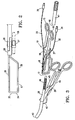
- Figure 1 is a perspective view of a uterine artery intravaginal device which embodies features of the invention.
- Figure 2 is a side view of the distal portion of the uterine artery intravaginal device shown in Figure 1 .
- Figure 3 is an exploded perspective view of a system including the intravaginal device shown in Figure 1 and a tenaculum-type device configured to slidably receive the intravaginal device.
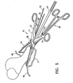
- Figure 5 is an perspective view of the intravaginal device shown in Figure 1 mounted on the shaft of the tenaculum-like device shown in Figure 3 .
- Figure 6 is a perspective view of the intravaginal device mounted on the shaft of the tenaculum-like device shown in Figure 4 with the pressure applying surfaces of the intravaginal device pressing against the patient's uterine arteries.
- the treatment embodying features of the invention basically involves occluding one or both of the patient's uterine arteries with a device to form thrombus within the occluded artery or arteries and administering an agent to the patient which will allow for occlusion of the artery or arteries to be prolonged after removal of the device.
- the agent may act to prevent lysis of the thrombus or may act to reduce uterine blood flow.
- FIGS 1 and 2 illustrate a relatively non-invasive intra-vaginal device 10 embodying features of the invention.
- the device 10 includes a pair of elongated clamping members 11 and 12, each of which has an elongated handle 13 and 14 respectively with finger grips 15 and 16 on the proximal ends of the handles.
- Clamping jaws 17 and 18 are secured to the distal ends 20 and 21 respectively of handles 13 and 14.
- the clamping jaws 17 and 18 are provided with pressure-applying surfaces 22 and 23 respectively on the distal ends 24 and 25 of the clamping elements.
- the handles 13 and 14 are pivotally connected at pivot point 26 to facilitate the opening and closing of the clamping jaws 17 and 18.
- a shoe slider 27 (shown in Figure 2 ) is provided on the under side of the intravaginal device 10 for mounting the intravaginal device to the shaft 28 of a tenaculum like device 29 (as shown in Figure 3 ) to guide the intravaginal device 10 to the patient's uterine cervix.
- Blood flow sensors 30 and 31 are secured to the pressure applying surfaces 22 and 23 respectively.
- Conductors 32 and 33 are electrically connected by their distal ends to the sensors 30 and 31 and extend proximally.
- the proximal ends of the conductors 32 and 33 have adaptors 34 and 35 to be operatively connected to power source (not shown) with an audio or video display to convert the sensed blood flow signal from the sensors to actuate an audible report or a video display representing the blood flow sensed.
- the clamping jaws 17 and 18 shown in Figures 1 and 2 are open, paddle-like members which have opposed tissue receiving recesses 36 and 37 proximal to the distal ends 24 and 25 of the jaws 17 and 18 which are defined in part by longitudinally oriented top side element 38 and bottom side element 39 for recess 36 and top side element 40 and bottom side element 41 for recess 37.
- the proximal ends of the side elements 38-41 are secured to the distal ends 24 and 25 of handles 13 and 14.
- the top side elements 38 and 40 of the clamping elements are essentially in line with the distal ends 24 and 25 of the handles 13 and 14.
- the bottom side elements 39 and 41 are spaced away from the top elements and preferably extend below the shoe slider 27 so that the distal ends 24 and 25 of the clamping elements 17 and 18 are equally disposed above and below the shaft 28 of tenaculum-like device 29 (shown in Figures 2 and 3 ) to properly engage the patients vaginal fornix and to apply pressure to the underlying uterine arteries to occlude these arteries.
- FIG 3 is an exploded view of the system embodying features of the invention including the intravaginal device 10 described above and the tenaculum-like device 29.
- the tenaculum-like device has a pointed distal tip 42 configured to engage tissue of the patient's uterine cervix.
- the distal tip 43 of the shaft 28 is flared as shown to maintain the tip within the patient's uterine cervix 44 during the procedure.
- Handles 45 and 46 allow movement between the tip 42 and the shaft 28 to manipulate the patient's uterine cervix.
- Sheath 47 is provided with internal threads (not shown) within its distal end 48 which are configured to engage the threads 49 on the shaft 28 to prevent the withdrawal of the intravaginal device during the procedure.
- Figure 4 illustrates the deployment of the tenaculum like device 29 within the patient's vaginal canal (not shown) with the shaft 28 of the tenaculum-like device inserted into the patient's uterine cervix 44.
- the handle 45 of the tenaculum-like device 29 has a sharp distal element 43 for engaging cervical tissue to be able to manipulate the patent's uterine cervix during the procedure when positioning the intravaginal device 10 about the patient's uterine cervix 44.
- Handle 46 is secured to the mid-point of the shaft 28.
- the intravaginal device 10 is mounted onto the shaft 28 of the tenaculum-like device 29 with the shaft 28 slidably extending within the shoe slide 27.
- the intravaginal device 10 is advanced within the patient's vaginal canal (not shown) over the shaft 28 of the tenaculum-like device 29 until the open jaws 17 and 18 of the device 10 extend over the end of the patient's uterine cervix as shown in Figure 5 .
- the distal ends 24 and 25 are urged against the patient's vaginal fornix on both sides of the cervix 44.
- the position of the distal ends 24 and 25 is adjusted to facilitate use of the blood flow sensors 30 and 31 on the pressure applying surfaces 22 and 23 to detect the underlying uterine arteries 45 and 46.
- the operator squeezes the finger grips 15 and 16 on the proximal ends of handles 13 and 14 to press the pressure applying surfaces against the patient's vaginal fornix to occlude the underlying uterine arteries as shown in Figure 6 .
- the ratchet locks 50 and 51 on the handles 13 and 14 adjacent the finger grips 15 and 16 engage to lock the handles 13 and 14 together with the pressure applying surfaces 22 and 23 of the jaws 17 and 18 pressed against the vaginal fornix with the underlying uterine arteries 45 and 46 occluded.
- the blood flow sensors 30 and 31 can be employed to monitor the blood flow through the uterine arteries 45 and 46 and to detect blood flow termination when the arteries are occluded.
- the clamping jaws 17 and 18 are locked position about 0.5 to about 3 hours, preferably about 1 to about 2 hours for effective occluding of the patient's uterine arteries.
- thrombus forms in the arteries.
- An agent can be administered to the patient in addition to the clamping to enhance the effects of the occluded artery and decrease the time necessary for the device to remain in place.
- the presently preferred plasminogen binding agent is tranexamic acid (TA).
- TA tranexamic acid
- the TA is delivered to the patient intravenously. Initially, the patients are given 10mg TA/kg of patient weight over a thirty minute period, followed by a constant drip at 1 mg TA/kg of body weight for the duration of the treatment time.
- An alternative plasminogen binding agent is ethamsylate, but this agent is not as effective as tranexamic acid and is required in much larger doses.
- Other anti-fibrinolytic agents include acexamic acid, aminocaproic acid and aprotinin.
- lysis of the thrombus within the occluded uterine arteries begins about a half an hour after the administration of the anti-fibrinolytic agent has been terminated.
- the thrombus has been completely lysed and full blood flow resumes.
- misoprostol Another agent which can enchance the effects of the clamping of the uterine arteries is misoprostol.
- An effective level of Misoprostol can reduce blood flow in the uterus and reduce the amount of fibrinolytic agent reaching the thrombus thereby extending the period in which the thrombus will remain in place.
- other agents capable of reducing uterine artery blood flow can be administered.
- the uterine artery intravaginal devices embodying features of the invention can be made from any suitable material or combination of materials, including metals such as stainless steel, cobalt-chromium alloys, cobalt-chromium-nickel alloys, chromium-cobalt-molybdenum alloys and superelastic alloys such as nickel-titanium alloys having a stable austenite phase at body temperature, high strength plastics, ceramics, and other materials known in the art to be suitable for the uses contemplated herein.
- Biocompatible polymers such as polycarbonate, polysulfone, polyester, polyacetal and a variety of fluoropolymers can be suitable for a variety of embodiments of the invention.
- the intravaginal devices and systems embodying features of the invention can be designed for single use (disposable) or can be sterilizable and capable of multiple use.
Abstract
Description
- The invention is generally directed to the treatment of uterine disorders by detecting and regulating blood flow through one or both of the patient's uterine arteries.
- Hysterectomy (surgical removal of the uterus) is performed on approximately 600,000 women annually in the United States. Hysterectomy is often the therapeutic choice for the treatment of uterine cancer, adenomyosis, menorrhagia, prolapse, dysfunctional uterine bleeding (abnormal menstrual bleeding that has no discrete anatomic explanation such as a tumor or growth), and muscular tumors of the uterus, known as leimyoma or uterine fibroids.
- However, hysterectomy is a drastic treatment, having many undesirable characteristics. Thus, any method which can approximate the therapeutic result of a hysterectomy without removing the uterus would be a significant improvement in this field. Newer treatment methods have been developed for some diseases which may spare these women a hysterectomy.
- In an article published in 1964, Bateman reported that uterine artery vessel ligation or division achieved via infra-abdominal surgery similar to hysterectomy, was effective in treating menorrhagia both with and without myomectomy. Bateman, W., M.D., "Treatment of intractable menorrhagia by bilateral uterine vessel interruption", 89 Am. J. Obstet. Gynecol. 825-827 (Harcourt Health Sciences, July 15, 1964). While Bateman reported some success, this procedure involves opening the abdominal cavity, with the known attendant risks and disadvantages.
- In 1995, it was demonstrated that uterine fibroids could be treated without hysterectomy using a non-surgical therapy, specifically comprising bilateral intraluminal occlusion of the uterine arteries (Ravina et al., "Arterial Embolization to Treat Uterine Myomata", Lancet Sept. 9, 1995; Vol. 346; pp. 671-672). This technique is known as "uterine artery embolization". In this technique, uterine arteries are accessed via a transvascular route from a common femoral artery into the left and right uterine arteries by means of an intravascular catheter and embolic material, such as small metallic coils, polyvinyl alcohol particulate and the like, is delivered through the catheter to the uterine arteries which quickly become occluded.
- See also Burbank, Fred, M.D., et al, Uterine Artery Occlusion by Embolization or Surgery for the Treatment of Fibroids: A Unifying Hypothesis Transient Uterine Ischemia, The Journal of the American Association of Gynecologic Laparoscopists, November 2000, Vol. 7, No. 4 Supplement, pp. S3-S49.
U.S. Patent No. 6,254,601, to Fred Burbank et al , entitled "Methods for Occlusion of the Uterine Arteries", describes numerous devices and methods useful for occluding a uterine artery by penetrating the tissue of the patient to access the uterine artery. The devices and methods described in Burbank '601 have been useful in occluding a uterine artery, however there have been some difficulties encountered with their use. - The uterus has a dual (or redundant) blood supply, the primary blood supply being from the bilateral uterine arteries, and the secondary blood supply from the bilateral ovarian arteries. Consequently, when both uterine arteries are occluded, i.e. bilateral vessel occlusion, the uterus and the fibroids contained within the uterus are both deprived of their blood supply. However, as demonstrated by Ravina et al. and Burbank et al., the ischemic effects on the fibroid is greater than the effect on the uterus. In most instances, the fibroid withers and ceases to cause clinical symptoms.
- However, many physicians do not possess the training or equipment necessary to perform catheter-based uterine artery embolization under radiologic direction. Accordingly, there are substantially fewer uterine artery embolizations performed, worldwide, each year than hysterectomies for symptomatic uterine fibroids and other uterine disorders.
- Recently, fibroid treatment procedures have been described wherein the uterine arteries are temporarily occluded by an intravaginal device which is clamped or otherwise pressed against a tissue bundle with the patient's uterine artery being within the bundle. Pressure on the tissue occludes the underlying uterine artery causing thrombus to form in the occluded artery. While these procedures have shown much promise, they typically take about six hours for completely effective treatment, which means the patient must be under observation and frequently sedated during the period.
-
US 2004/153105 discloses an intravaginal device for treating a .female patient's uterine disorder by occluding at least one of the patient's uterine arteries, comprising: - a. a first clamping member which has
- i. an elongated handle with a proximal handle portion configured to extend out of the patient during treatment and be manipulated by an operator, which has a distal handle portion having a pivot point and which is configured to rotate in a plane about the pivot point, and
- ii. an open, paddle-shaped jaw which is secured to the distal handle portion, which has a distal tip with a pressure applying surface, which has a tissue receiving recess proximal to the pressure applying surface with a pair of longitudinally oriented sides proximal to the distal tip defining in part the tissue receiving recess, with the first and second longitudinally oriented sides spaced away from the plane of the distal handle portion; and
- b. a second clamping member which has
- i. an elongated handle with a proximal handle portion configured to extend out of the patient during treatment and be manipulated by an operator along with the proximal handle portion of the first clamping member, which has a distal handle portion having a pivot point pivotally secured to the pivot point of the handle of the first clamping member, and
- ii. a stabilizing member which is secured to the distal handle portion, which has a pressure applying surface opposed to the pressure applying surface of the first clamping member.
-
US 2004/092979 discloses an intravaginal device for treating a female patient's uterine disorder by occluding at least one of the patient's uterine arteries, comprising: - a. a first clamping member which has
- i. an elongated handle with a proximal handle portion configured to extend out of the patient during treatment and be manipulated by an operator, which has a distal handle portion having a pivot point and which is configured to rotate in a plane about the pivot point, and
- ii. an open, paddle-shaped jaw which is secured to the distal handle portion, which has a distal tip with a pressure applying surface; and
- b. a second clamping member which has
- i. an elongated handle with a proximal handle portion configured to extend out of the patient during treatment and be manipulated by an operator along with the proximal handle portion of the first clamping member, which has a distal handle portion having a pivot point pivotally secured to the pivot point of the handle of the first clamping member, and
- ii. an open, paddle-shaped jaw which is secured to the distal handle portion, which has a distal tip with a pressure applying surface opposed to the pressure applying surface of the first clamping member.
- What is needed, therefore, are intravaginal devices and procedures for using such devices which can be easily used by physicians with limited training to occlude blood flow in a female patents uterine arteries and which reduces the period the patient's uterine arteries must be clamped.
- The invention is directed to a device for treating a female patient's uterine disorder by occluding one or both of the patient's uterine arteries. The treatment is suitable for uterine disorders such as uterine fibroids, dysfunctional uterine bleeding (DUB), and post partum hemorrhage (PPH) by reducing or terminating blood flow through one or both of the female patient's uterine arteries.
- The treatment embodying features of the invention basically involves occluding one or both of the patient's uterine arteries with an intravaginal device to form a thrombus within the occluded artery or arteries and administering an agent which will prolong the occlusion of the artery or arteries after removal of the occluding device or initiate or accelerate fibroid cell apoptosis (programmed cell death). The agent may act to retard or prevent lysis of the thrombus or may act to reduce uterine blood flow which can retard lysis. The agent can be an anti-fibrinolytic agent administered to the patient to retard or prevent lysis of the thrombus formed by the uterine artery occlusion for essentially the duration of the treatment. By maintaining an effective amount of the anti-fibrinolytic agent within the patient's blood stream, the lysis of the thrombus within the uterine arteries after the occluding device (e.g. clamp) is removed is retarded or prevented. This allows the occluding device to be removed earlier thereby shortening the clamping period. Moreover, the uterine artery occlusion after occluding device removal can be extended by maintaining an effective level of anti-fibrinolytic agent within the patient.
- After the uterine arteries have been occluded for a sufficient time, the administration of the anti-fibrinolytic agent can be terminated so that lysis of the thrombus is initiated by the normal lysis cycle and blood flow through the arteries can resume. Administering the anti-fibrinolytic agent allows for blood stasis to occur within the uterus and eliminates or retards the clot lysis cycle which can minimize the effect of the treatment. The stasis in the uterus initiates a clotting cascade and by minimizing the competitive lysis cycle a quicker treatment can be delivered. The clot is maintained after removal of the occlusion system by the continued administration of the anti-fibrinolytic agent.
- The preferred anti-fibrinolytic agent is a plasminogen binding agent which is believed to bind to plasminogen and prevents tissue plasminogen activator (tPa) and urine plasminogen activator (uPa) from binding with plasminogen. When tPa and the uPa bind with the plasminogen to generate plasmin which solubilizes (lyses) fibrin clots and also degrades various proteins including fibrinogen and coagulation factors. The presently preferred plasminogen binding agent is tranexamic acid (TA). Typically, the TA is delivered to the patient intravenously. An alternative plasminogen binding agent is ethamsylate, but this agent is not as effective as tranexamic acid and is required in much larger doses. Other anti-fibrinolytic agents include acexamic acid, aminocaproic acid and aprotinin.
- Another agent which can enchance the effects of the clamping of the uterine arteries is misoprostol. An effective level of Misoprostol can reduce blood flow in the uterus and reduce the amount of fibrinolytic agent reaching the thrombus thereby extending the period in which the thrombus will remain in place. Additionally, other agents capable of reducing uterine artery blood flow can be administered.
- Agents which stimulate production of Bax and Bak proteins can be administered as well to augment fibroid tissue necrosis. Bax and Bak are proteins which promote apoptosis or programmed cell death. Bax and Bak protein levels are elevated in ischemic fibroid tissue. The proto-oncogene Bcl-2 is found in abundance in the cells of a fibroid, compared to normal myometrial cells. Bcl-2 is believed to play an important role in the growth of tumors. An agent which inhibits the protein expression of Bcl-2 can be used to treat fibroids. Furthermore, agents which produce effects similar to those created by inhibition Bcl-2 or stimulation of Bax or Bak, can be administered to aid in treatment of fibroids.
- An intravaginal device embodying features of the invention is set forth in the accompanying claim 1.
Further aspects of the invention are set forth in the accompanying dependent claims. - A method for occluding a patient's uterine arteries is disclosed, but not claimed, and includes advancing the intravaginal device through the patient's vaginal canal, preferably slidably mounted on a previously deployed tenaculum or tenaculum-like device. The stabilizing shaft of the tenaculum-like device, which is partially deployed within the patient's uterine cervix, guides the intravaginal device so that the clamping jaws of the device are disposed adjacent to the sides of the patient's cervix. The positions of the pressure applying surfaces of the clamping jaws are adjusted utilizing the blood flow sensors to ensure that the pressure applying surfaces on the clamping jaws are properly positioned with respect to the uterine arteries for effective occlusion thereof.
- The invention allows for the non-surgical location and occlusion of blood vessels such as the uterine artery, providing effective therapeutic treatment Importantly, the present invention allows for the occlusion of a female patient's uterine artery without the need for radiographic equipment or for extensive training in the use of radiographic techniques. The devices and methods are simple and readily used for treating uterine fibroids, dysfunctional uterine bleeding (DUB), adenomyosis, post-partum hemorrhage, and other uterine disorders. The mechanical occlusion portion of the treatment period is shortened considerably by the administration of an anti-fibrinolytic agent to the patient to maintain the occluding thrombus within the patient's uterine arteries. The shortened treatment times allows the patient to be more mobile, simplifies the treatment and reduces the patient monitoring and care needed. Furthermore, reduced artery clamping periods reduces the trauma to the patient's cervix and vaginal mucosa. The shorter treatment periods also increases the number of patients which can be treated over a given period.
- These and other advantages will become more apparent from the following detailed description when taken in conjunction with the accompanying exemplary drawings.
-
Figure 1 is a perspective view of a uterine artery intravaginal device which embodies features of the invention. -
Figure 2 is a side view of the distal portion of the uterine artery intravaginal device shown inFigure 1 . -
Figure 3 is an exploded perspective view of a system including the intravaginal device shown inFigure 1 and a tenaculum-type device configured to slidably receive the intravaginal device. -
Figure 4 is a perspective view of a tenaculum-type device mounted within a patient's uterine cervix. -
Figure 5 is an perspective view of the intravaginal device shown inFigure 1 mounted on the shaft of the tenaculum-like device shown inFigure 3 . -
Figure 6 is a perspective view of the intravaginal device mounted on the shaft of the tenaculum-like device shown inFigure 4 with the pressure applying surfaces of the intravaginal device pressing against the patient's uterine arteries. - Although the invention is described by reference to occlusion of a patient's uterine arteries, no claim is made herein to a method of treatment by surgery.
- The treatment embodying features of the invention basically involves occluding one or both of the patient's uterine arteries with a device to form thrombus within the occluded artery or arteries and administering an agent to the patient which will allow for occlusion of the artery or arteries to be prolonged after removal of the device. The agent may act to prevent lysis of the thrombus or may act to reduce uterine blood flow.
-
Figures 1 and2 illustrate a relatively non-invasiveintra-vaginal device 10 embodying features of the invention. Thedevice 10 includes a pair ofelongated clamping members handle jaws handles jaws surfaces handles pivot point 26 to facilitate the opening and closing of the clampingjaws Figure 2 ) is provided on the under side of theintravaginal device 10 for mounting the intravaginal device to theshaft 28 of a tenaculum like device 29 (as shown inFigure 3 ) to guide theintravaginal device 10 to the patient's uterine cervix. -
Blood flow sensors pressure applying surfaces Conductors sensors conductors adaptors - The clamping
jaws Figures 1 and2 are open, paddle-like members which have opposed tissue receiving recesses 36 and 37 proximal to the distal ends 24 and 25 of thejaws top side element 38 andbottom side element 39 forrecess 36 andtop side element 40 andbottom side element 41 forrecess 37. The proximal ends of the side elements 38-41 are secured to the distal ends 24 and 25 ofhandles top side elements handles bottom side elements shoe slider 27 so that the distal ends 24 and 25 of the clampingelements shaft 28 of tenaculum-like device 29 (shown inFigures 2 and 3 ) to properly engage the patients vaginal fornix and to apply pressure to the underlying uterine arteries to occlude these arteries. -
Figure 3 is an exploded view of the system embodying features of the invention including theintravaginal device 10 described above and the tenaculum-like device 29. The tenaculum-like device has a pointeddistal tip 42 configured to engage tissue of the patient's uterine cervix. Thedistal tip 43 of theshaft 28 is flared as shown to maintain the tip within the patient'suterine cervix 44 during the procedure.Handles tip 42 and theshaft 28 to manipulate the patient's uterine cervix.Sheath 47 is provided with internal threads (not shown) within itsdistal end 48 which are configured to engage thethreads 49 on theshaft 28 to prevent the withdrawal of the intravaginal device during the procedure. Details of thetenaculum device 29 are found in co-pending application Serial No.10/300,420, filed on November, 19, 2002 US 2004/0097961 ), and co-pending application Serial No.10/716,329, filed on November 18, 2003 US 2004/0158262 ), both of which are assigned to the present assignee. -
Figure 4 illustrates the deployment of the tenaculum likedevice 29 within the patient's vaginal canal (not shown) with theshaft 28 of the tenaculum-like device inserted into the patient'suterine cervix 44. Thehandle 45 of the tenaculum-like device 29 has a sharpdistal element 43 for engaging cervical tissue to be able to manipulate the patent's uterine cervix during the procedure when positioning theintravaginal device 10 about the patient'suterine cervix 44.Handle 46 is secured to the mid-point of theshaft 28. - As shown in
Figure 5 , theintravaginal device 10 is mounted onto theshaft 28 of the tenaculum-like device 29 with theshaft 28 slidably extending within theshoe slide 27. Theintravaginal device 10 is advanced within the patient's vaginal canal (not shown) over theshaft 28 of the tenaculum-like device 29 until theopen jaws device 10 extend over the end of the patient's uterine cervix as shown inFigure 5 . The distal ends 24 and 25 are urged against the patient's vaginal fornix on both sides of thecervix 44. The position of the distal ends 24 and 25 is adjusted to facilitate use of theblood flow sensors pressure applying surfaces uterine arteries handles Figure 6 . The ratchet locks 50 and 51 on thehandles handles pressure applying surfaces jaws uterine arteries blood flow sensors uterine arteries - The
blood flow sensors jaws uterine arteries - Suitable Doppler ultrasonic systems include the MedaSonics® CardioBeat® Blood Flow Doppler with Integrated Speaker (Cooper Surgical, Inc., Trumbull, CT). Other commercially available suitable Doppler ultrasound sensors are the Koven model ES 100X MiniDop VRP-8 probe (St. Louis, MO) and the DWL/Neuro Scan Medical Systems' Multi-Dop B+ system (Sterling, VA).
- While not shown in the drawings, the pressure applying surface of the occluding elements can be provided with a serrated or other tissue-grasping surface which is configured to engage and hold onto tissue when the pressure applying surfaces are pressed into tissue of the patient's vaginal fornix.
- The uterine arteries in human females are located adjacent the vaginal mucosa at a location within a few centimeters of the vaginal fornix. As a result, for accessing and occluding a uterine artery from within the patient's vaginal canal, the dimensions of a vagina determine what size intravaginal device is suitable, taking into consideration that the intravaginal device should readily reach the vaginal fornix and be manually operated from outside of a patient's body. For example, a intravaginal device can be between about 6 inch to about 12 inches (15.2-30.5 mm) in length for most applications.
- The clamping
jaws - The agent can be an anti-fibrinolytic agent, which retards or prevents lysis of the thrombus formed by the uterine artery occlusion for essentially the duration of the treatment. By maintaining an effective amount of the anti-fibrinolytic agent within the patient's blood stream, the lysis of thrombus within the uterine arteries is retarded or prevented, so the thrombus formation is accelerated, reducing the clamping period. Moreover, the uterine artery occlusion can be extended by maintaining an effective level of anti-fibrinolytic agent within the patient after the clamping pressure by the intravaginal device has been released.
- After the uterine arteries have been occluded for a sufficient time, the administration of the anti-fibrinolytic agent can be terminated so that lysis of the thrombus is initiated by the normal lysis cycle and blood flow through the arteries can resume. By administering the anti-fibrinolytic agent allows for blood stasis to occur within the uterus and but eliminates or retards the clot lysis cycle which can minimize the effect of the treatment. The stasis in the uterus initiates a clotting cascade and by minimizing the competitive lysis cycle a shorter treatment period can be obtained. The clot is maintained after removal of the occlusion system by maintaining an effective level of the anti-fibrinolytic agent within the patient.
- If the thrombus is not lysed, the thrombus effectively blocks blood flow through the artery, so the clamping jaw is no longer needed and it can be removed. Preferably, the anti-fibrinolytic agent has been administered to the patient and an effective level of the agent is developed within the patient's blood before the jaws of the intravaginal device are clamped together to occlude the patient's uterine arteries.
- The preferred anti-fibrinolytic agent is a plasminogen binding agent which is believed to bind to plasminogen and prevents tissue plasminogen activator (tPa) and urine plasminogen activator (uPa) from binding with plasminogen. When tPa and the uPa bind with the plasminogen to generate plasmin which solubilizes (lyses) fibrin clots and also degrades various proteins including fibrinogen and coagulation factors.
- The presently preferred plasminogen binding agent is tranexamic acid (TA). Typically, the TA is delivered to the patient intravenously. Initially, the patients are given 10mg TA/kg of patient weight over a thirty minute period, followed by a constant drip at 1 mg TA/kg of body weight for the duration of the treatment time. An alternative plasminogen binding agent is ethamsylate, but this agent is not as effective as tranexamic acid and is required in much larger doses. Other anti-fibrinolytic agents include acexamic acid, aminocaproic acid and aprotinin.
- By maintaining an anti-fibrinolytic agent within the patient's blood, clot formation from the artery occlusion is accelerated because the clot lysis cycle is retarded or eliminated allowing for reduced occlusion times. When an anti-fibrinolytic agent is used to accelerate the uterine artery occlusion, the uterine arteries should be occluded for a period of about 0.5 to about 3 hours, usually about 1 to about 2 hours for effective treatment of the uterine disorder. The uterine artery occlusion can be extended after the clamping members of the intravaginal device have been released by the continued administration of the anti-fibrinolytic agents to the patient. By retarding or preventing lysis of the thrombus within the patient's uterine arteries and uterus, the arteries remain occluded even though the pressure applied by the jaws of the intravaginal device have been released. The occluding thrombus is maintained within the patient's uterus and uterine arteries to provide a total artery occlusion time period of about 1 to about 48 hours, preferably about 1 to about 24 hours for effective treatments of the patient's uterine disorder. Typically, the total occlusion time will be less than 6 hours
- At the end of the treatment, administration of the anti-fibrinolytic agents is terminated. Typically lysis of the thrombus within the occluded uterine arteries begins about a half an hour after the administration of the anti-fibrinolytic agent has been terminated. Within about 24 hours the thrombus has been completely lysed and full blood flow resumes.
- Another agent which can enchance the effects of the clamping of the uterine arteries is misoprostol. An effective level of Misoprostol can reduce blood flow in the uterus and reduce the amount of fibrinolytic agent reaching the thrombus thereby extending the period in which the thrombus will remain in place. Additionally, other agents capable of reducing uterine artery blood flow can be administered.
- Agents which stimulate production of Bax and Bak proteins can be administered as well to augment fibroid tissue necrosis. Bax and Bak are proteins which promote apoptosis or programmed cell death. Bax and Bak protein levels are elevated in ischemic fibroid tissue. The proto-oncogene Bcl-2 is found in abundance in the cells of a fibroid, compared to normal myometrial cells. Bcl-2 is believed to play an important role in the growth of tumors. An agent which inhibits the protein expression of Bcl-2 can be used to treat fibroids. Furthermore, agents which produce effects similar to those created by inhibition Bcl-2 or stimulation of Bax or Bak, can be administered to aid in treatment of fibroids.
- The uterine artery intravaginal devices embodying features of the invention can be made from any suitable material or combination of materials, including metals such as stainless steel, cobalt-chromium alloys, cobalt-chromium-nickel alloys, chromium-cobalt-molybdenum alloys and superelastic alloys such as nickel-titanium alloys having a stable austenite phase at body temperature, high strength plastics, ceramics, and other materials known in the art to be suitable for the uses contemplated herein. Biocompatible polymers such as polycarbonate, polysulfone, polyester, polyacetal and a variety of fluoropolymers can be suitable for a variety of embodiments of the invention. The intravaginal devices and systems embodying features of the invention can be designed for single use (disposable) or can be sterilizable and capable of multiple use.
- While particular forms of the invention have been illustrated and described, it will be apparent that various modifications can be made to the invention and that individual features shown in one embodiment can be combined with any or all the features of another embodiment described herein. The intravaginal device described herein is a presently preferred embodiments, but other uterine artery intravaginal devices can be utilized to carry out methods of the type generally described above. For example, other suitable intravaginal devices are described in co-pending applications Serial No.
10/107,810, filed on March 28, 2002 US 6,905,506 ) Serial No.10/107,800, filed on March 28, 2002 US 2002/0165579 ), Serial No.10/430,880, filed on May 6, 2003 US 6,582,449 ), Serial No.10/721,857, filed on November 25, 2003 US 2005/0113634 ) and Serial No.10/718,222, filed on November 20, 2003 US 7,325,546 ), all of which have been assigned to the present assignee. Accordingly, the invention is not to be limited to the specific embodiments illustrated and should be defined by the scope of the appended claims as broadly as the prior art will permit.
Claims (11)
- An intravaginal device (10) for treating a female patient's uterine disorder by occluding at least one of the patient's uterine arteries, comprising:a. a first clamping member (11) which hasi. an elongated handle (13) with a proximal handle portion configured to extend out of the patient during treatment and be manipulated by an operator, which has a distal handle portion (20) having a pivot point (26) and which is configured to rotate in a plane about the pivot point, andii. an open, paddle-shaped jaw (17) which is secured to the distal handle portion (20), which has a distal tip (24) with a pressure applying surface (22), which has a tissue receiving recess (36) proximal to the pressure applying surface (22) with a pair of longitudinally oriented sides (38, 39) proximal to the distal tip defining in part the tissue receiving recess, with a first (38) of the longitudinally oriented sides in line with the distal handle portion (20) and a second (39) of the longitudinally oriented sides spaced away from the first longitudinally oriented side (38); andb. a second clamping member (12) which hasi. an elongated handle (14) with a proximal handle portion configured to extend out of the patient during treatment and be manipulated by an operator along with the proximal handle portion of the first clamping member (11), which has a distal handle portion (21) having a pivot point (26) pivotally secured to the pivot point (26) of the handle (13) of the first clamping member, andii. an open, paddle-shaped jaw (18) which is secured to the distal handle portion (21), which has a distal tip (25) with a pressure applying surface (23) opposed to the pressure applying surface (22) of the first clamping member (11), a tissue receiving recess (37) proximal to the pressure applying surface (23) extending away from the tissue receiving recess (36) of the first clamping member (11) with a pair of longitudinally oriented sides (40, 41) defining in part the tissue receiving recess (37), with a first (40) of the sides in line with the distal handle portion (21) and a second (41) of the sides spaced away from the first longitudinally oriented side (40).
- The intravaginal device of claim 1 wherein each of the proximal shaft sections of the clamping members (11, 12) include a grip (15, 16) configured to receive an operator's finger.
- The intravaginal device of claim 1 wherein at least one of the clamping members (11, 12) has a blood flow sensor (30; 31) on its distal tip (24; 25) for detecting the location of the patient's uterine artery.
- The intravaginal device of claim 1 wherein the blood flow sensor (30; 31) is a Doppler crystal.
- The intravaginal device of claim 4 wherein the Doppler crystal is mounted in the pressure applying surface (22; 23) of the distal tip (24; 25).
- The intravaginal device of claim 5 wherein the Doppler crystal has a direction of view away from the pressure applying surface (22; 23).
- The intravaginal device of claim 1 wherein the pair of longitudinally oriented sides (38, 39; 40, 41) of the clamping members (11, 12) are spaced apart a distance of 1 to 20 mm, preferably a distance of 5 to 10 mm.
- The intravaginal device of claim 1 wherein the distal end (24) of the paddle-shaped jaw (17) of the first clamping member (11) and the distal end (25) of the paddle-shaped jaw (18) of the second clamping member (12) are configured to engage a patient's vaginal fornix on opposite sides of the patient's uterine cervix.
- The intravaginal device of claim 1 wherein the device (10) is adapted to be mounted to a tenaculum-like device (29) to guide the device to the patient's uterine cervix.
- The intravaginal device of claim 9 wherein the device (10) has a shoe slider (27) for mounting the device to the tenaculum-like device (29).
- The intravaginal device of claim 10 wherein the second longitudinally oriented sides (39, 41) are spaced from the first longitudinally oriented sides (38, 40) and extend beyond the shoe slider (27) so that the distal ends (24, 25) of the clamping elements (17, 18) are equally disposed on either side of a shaft (28) of the tenaculum-like device (29) when the device (10) is, in use, mounted to the tenaculum-like device.
Applications Claiming Priority (3)
| Application Number | Priority Date | Filing Date | Title |
|---|---|---|---|
| US62275104P | 2004-10-27 | 2004-10-27 | |
| US11/256,768 US7875036B2 (en) | 2004-10-27 | 2005-10-24 | Short term treatment for uterine disorder |
| PCT/US2005/038393 WO2006049960A1 (en) | 2004-10-27 | 2005-10-25 | Short term treatment for uterine disorder |
Publications (2)
| Publication Number | Publication Date |
|---|---|
| EP1811909A1 EP1811909A1 (en) | 2007-08-01 |
| EP1811909B1 true EP1811909B1 (en) | 2011-02-16 |
Family
ID=35781301
Family Applications (1)
| Application Number | Title | Priority Date | Filing Date |
|---|---|---|---|
| EP05817246A Active EP1811909B1 (en) | 2004-10-27 | 2005-10-25 | Device for short term treatment of uterine disorder |
Country Status (9)
| Country | Link |
|---|---|
| US (1) | US7875036B2 (en) |
| EP (1) | EP1811909B1 (en) |
| JP (1) | JP4782140B2 (en) |
| KR (1) | KR20080004446A (en) |
| AT (1) | ATE498365T1 (en) |
| AU (1) | AU2005302600B2 (en) |
| CA (1) | CA2585545A1 (en) |
| DE (1) | DE602005026429D1 (en) |
| WO (1) | WO2006049960A1 (en) |
Families Citing this family (14)
| Publication number | Priority date | Publication date | Assignee | Title |
|---|---|---|---|---|
| US7004965B2 (en) * | 2003-12-17 | 2006-02-28 | Yosef Gross | Implant and delivery tool therefor |
| US20090093758A1 (en) * | 2006-07-24 | 2009-04-09 | Yossi Gross | Fibroid treatment apparatus and method |
| US20100130815A1 (en) * | 2007-05-18 | 2010-05-27 | Prostaplant Ltd. | Intraurethral and extraurethral apparatus |
| US20090054915A1 (en) * | 2007-08-23 | 2009-02-26 | Peter Meier | Obstruction of uterine arteries to treat uterine fibroids using mechanical instruments to twist the vessels |
| US20090054916A1 (en) * | 2007-08-23 | 2009-02-26 | Peter Meier | Clip-based method for treatment of uterine fibroids by obstruction of the uterine arteries |
| US20090062827A1 (en) * | 2007-08-31 | 2009-03-05 | Peter Meier | Vacuum-based method for obstruction of uterine arteries to treat uterine fibroids |
| US8551002B2 (en) * | 2008-12-12 | 2013-10-08 | Immersion Corporation | Spatial array of sensors mounted on a tool |
| US8403953B2 (en) * | 2009-07-27 | 2013-03-26 | Fibro Control, Inc. | Balloon with rigid tube for occluding the uterine artery |
| US8608738B2 (en) | 2010-12-06 | 2013-12-17 | Soulor Surgical, Inc. | Apparatus for treating a portion of a reproductive system and related methods of use |
| MX2012004494A (en) | 2012-04-17 | 2013-10-17 | Arnoldo Guzman Sanchez | Compressive system for reducing edge bleeding in classical hysterotomy in cases of placenta praevia. |
| EP2859855B1 (en) * | 2013-10-08 | 2017-04-05 | Karl Leibinger Medizintechnik Gmbh & Co. Kg | Repositioning pliers with dual 90° deformation for distribution on two levels |
| WO2017042294A1 (en) * | 2015-09-11 | 2017-03-16 | Atropos Limited | Tenaculum |
| CN112770680A (en) | 2018-08-17 | 2021-05-07 | 安普列斯医疗公司 | Device and method for compression of tumors |
| US11419610B2 (en) | 2018-08-17 | 2022-08-23 | Empress Medical, Inc. | Device and method for passing tension member around tissue mass |
Family Cites Families (127)
| Publication number | Priority date | Publication date | Assignee | Title |
|---|---|---|---|---|
| US3209753A (en) * | 1962-05-04 | 1965-10-05 | Donald B Hawkins | Intestinal clamps and the like |
| US3411505A (en) | 1965-12-15 | 1968-11-19 | Paul D. Nobis | Device for interrupting arterial flow |
| US3779248A (en) | 1971-10-18 | 1973-12-18 | Medical Concepts Inc | Forceps |
| US4120302A (en) * | 1976-10-08 | 1978-10-17 | American Hospital Supply Corporation | Disposable pads for surgical instruments |
| US4428374A (en) * | 1978-12-20 | 1984-01-31 | Auburn Robert M | Umbilical cord clamping assembly |
| US4292960A (en) * | 1979-04-30 | 1981-10-06 | Rca Corporation | Apparatus and method for application of radioactive and microwave energy to the body |
| US4226240A (en) * | 1979-05-30 | 1980-10-07 | Walker Jr William E | Surgical foreceps |
| IN151996B (en) | 1979-06-18 | 1983-09-17 | Ethicon Inc | |
| US4509528A (en) * | 1981-12-16 | 1985-04-09 | Harvinder Sahota | Hemostat with blood flow sensor |
| US4428379A (en) * | 1982-01-07 | 1984-01-31 | Technicare Corporation | Passive ultrasound needle probe locator |
| SU1072859A1 (en) | 1982-01-22 | 1984-02-15 | Донецкий государственный медицинский институт им.А.М.Горького | Intestinal forceps |
| US5370675A (en) * | 1992-08-12 | 1994-12-06 | Vidamed, Inc. | Medical probe device and method |
| US4650466A (en) * | 1985-11-01 | 1987-03-17 | Angiobrade Partners | Angioplasty device |
| US4991588A (en) * | 1986-07-21 | 1991-02-12 | Pfizer Hospital Products Group, Inc. | Doppler guide wire |
| US4757823A (en) * | 1987-01-27 | 1988-07-19 | Hofmeister John F | Method and apparatus for measuring uterine blood flow |
| US4994069A (en) * | 1988-11-02 | 1991-02-19 | Target Therapeutics | Vaso-occlusion coil and method |
| US4945896A (en) * | 1989-01-24 | 1990-08-07 | Gade George F | Surgical retractor assembly having tissue viability sensor embedded therein |
| US5289831A (en) * | 1989-03-09 | 1994-03-01 | Vance Products Incorporated | Surface-treated stent, catheter, cannula, and the like |
| US5201314A (en) * | 1989-03-09 | 1993-04-13 | Vance Products Incorporated | Echogenic devices, material and method |
| US5081997A (en) * | 1989-03-09 | 1992-01-21 | Vance Products Incorporated | Echogenic devices, material and method |
| US5749879A (en) * | 1989-08-16 | 1998-05-12 | Medtronic, Inc. | Device or apparatus for manipulating matter |
| US5108408A (en) * | 1990-04-20 | 1992-04-28 | Lally James J | Uterine-ring hysterectomy clamp |
| US5037433A (en) * | 1990-05-17 | 1991-08-06 | Wilk Peter J | Endoscopic suturing device and related method and suture |
| US5100423A (en) | 1990-08-21 | 1992-03-31 | Medical Engineering & Development Institute, Inc. | Ablation catheter |
| US5227181A (en) * | 1990-12-19 | 1993-07-13 | Mold-Masters Limited | Multi-cavity melt distribution manifold |
| US5261409A (en) | 1991-05-27 | 1993-11-16 | Sulzer Brothers Limited | Puncturing device for blood vessels |
| US5226911A (en) * | 1991-10-02 | 1993-07-13 | Target Therapeutics | Vasoocclusion coil with attached fibrous element(s) |
| US5662680A (en) * | 1991-10-18 | 1997-09-02 | Desai; Ashvin H. | Endoscopic surgical instrument |
| US5713896A (en) * | 1991-11-01 | 1998-02-03 | Medical Scientific, Inc. | Impedance feedback electrosurgical system |
| US5704361A (en) * | 1991-11-08 | 1998-01-06 | Mayo Foundation For Medical Education And Research | Volumetric image ultrasound transducer underfluid catheter system |
| US5277181A (en) | 1991-12-12 | 1994-01-11 | Vivascan Corporation | Noninvasive measurement of hematocrit and hemoglobin content by differential optical analysis |
| US5562680A (en) * | 1992-01-03 | 1996-10-08 | Hasson; Harrith M. | Apparatus for assisting the performance of pelvic endoscopic procedures |
| JPH07506991A (en) * | 1992-04-23 | 1995-08-03 | シメッド ライフ システムズ インコーポレイテッド | Apparatus and method for sealing vascular punctures |
| US5336231A (en) * | 1992-05-01 | 1994-08-09 | Adair Edwin Lloyd | Parallel channel fixation, repair and ligation suture device |
| US5443470A (en) * | 1992-05-01 | 1995-08-22 | Vesta Medical, Inc. | Method and apparatus for endometrial ablation |
| NL9201118A (en) * | 1992-06-24 | 1994-01-17 | Leuven K U Res & Dev | TOOL KIT FOR LAPAROSCOPIC VAGINAL HYSTERECTOMY. |
| US5672153A (en) * | 1992-08-12 | 1997-09-30 | Vidamed, Inc. | Medical probe device and method |
| US5368034A (en) | 1992-09-04 | 1994-11-29 | Boston Scientific Corporation | Method and apparatus for thrombolytic therapy |
| WO1994006460A1 (en) * | 1992-09-21 | 1994-03-31 | Vitaphore Corporation | Embolization plugs for blood vessels |
| CA2102084A1 (en) * | 1992-11-09 | 1994-05-10 | Howard C. Topel | Surgical cutting instrument for coring tissue affixed thereto |
| US5275166A (en) | 1992-11-16 | 1994-01-04 | Ethicon, Inc. | Method and apparatus for performing ultrasonic assisted surgical procedures |
| US5336229A (en) * | 1993-02-09 | 1994-08-09 | Laparomed Corporation | Dual ligating and dividing apparatus |
| US5383922A (en) * | 1993-03-15 | 1995-01-24 | Medtronic, Inc. | RF lead fixation and implantable lead |
| US5542944A (en) * | 1993-04-19 | 1996-08-06 | Bhatta; Krishan M. | Surgical device and method |
| US5496331A (en) * | 1993-07-28 | 1996-03-05 | Terumo Kabushiki Kaisha | Knot-forming instrument and method of forming knots |
| JPH09507645A (en) * | 1994-01-18 | 1997-08-05 | エンドバスキュラー・インコーポレイテッド | Vein ligation device and vein ligation method |
| ATE157275T1 (en) * | 1994-03-07 | 1997-09-15 | Maurer A Sa | DEVICE FOR FILTRATION OF FLUID MEDIA |
| US5458596A (en) * | 1994-05-06 | 1995-10-17 | Dorsal Orthopedic Corporation | Method and apparatus for controlled contraction of soft tissue |
| US5707349A (en) | 1994-05-09 | 1998-01-13 | Somnus Medical Technologies, Inc. | Method for treatment of air way obstructions |
| US5672172A (en) * | 1994-06-23 | 1997-09-30 | Vros Corporation | Surgical instrument with ultrasound pulse generator |
| US5549624A (en) * | 1994-06-24 | 1996-08-27 | Target Therapeutics, Inc. | Fibered vasooclusion coils |
| US5697942A (en) | 1994-07-31 | 1997-12-16 | Palti; Yoram | Internal vascular clamp |
| US6032673A (en) * | 1994-10-13 | 2000-03-07 | Femrx, Inc. | Methods and devices for tissue removal |
| US5702407A (en) | 1994-11-29 | 1997-12-30 | Olympus Optical Co., Ltd. | Ligating apparatus |
| US5588960A (en) | 1994-12-01 | 1996-12-31 | Vidamed, Inc. | Transurethral needle delivery device with cystoscope and method for treatment of urinary incontinence |
| US5614204A (en) * | 1995-01-23 | 1997-03-25 | The Regents Of The University Of California | Angiographic vascular occlusion agents and a method for hemostatic occlusion |
| US6019724A (en) * | 1995-02-22 | 2000-02-01 | Gronningsaeter; Aage | Method for ultrasound guidance during clinical procedures |
| US5715832A (en) * | 1995-02-28 | 1998-02-10 | Boston Scientific Corporation | Deflectable biopsy catheter |
| US5665096A (en) * | 1995-03-07 | 1997-09-09 | Yoon; Inbae | Needle driving apparatus and methods of suturing tissue |
| US5766135A (en) * | 1995-03-08 | 1998-06-16 | Terwilliger; Richard A. | Echogenic needle tip |
| US5817022A (en) | 1995-03-28 | 1998-10-06 | Sonometrics Corporation | System for displaying a 2-D ultrasound image within a 3-D viewing environment |
| US5899861A (en) * | 1995-03-31 | 1999-05-04 | Siemens Medical Systems, Inc. | 3-dimensional volume by aggregating ultrasound fields of view |
| US5626607A (en) * | 1995-04-03 | 1997-05-06 | Heartport, Inc. | Clamp assembly and method of use |
| US5570692A (en) | 1995-05-19 | 1996-11-05 | Hayashi Denki Co. Ltd. | Ultrasonic doppler blood flow detector for hemorrhoid artery ligation |
| GB2302025A (en) | 1995-06-10 | 1997-01-08 | Mark Steven Whiteley | Vascular doppler forceps |
| US5713371A (en) * | 1995-07-07 | 1998-02-03 | Sherman; Dani | Method of monitoring cervical dilatation during labor, and ultrasound transducer particularly useful in such method |
| US5658299A (en) * | 1995-07-20 | 1997-08-19 | Applied Medical Resources | Surgical ligating device and method for using same |
| DE19528440C2 (en) | 1995-08-02 | 1998-09-10 | Harald Dr Med Kuebler | Surgical cutting instrument |
| US5674243A (en) | 1995-08-03 | 1997-10-07 | Hale; Theodore Mark | Obstetrical forceps |
| US5747637A (en) * | 1995-09-07 | 1998-05-05 | Mitsui Toatsu Chemicals, Inc. | Bioabsorbable polymer and process for preparing the same |
| US5979453A (en) | 1995-11-09 | 1999-11-09 | Femrx, Inc. | Needle myolysis system for uterine fibriods |
| US5716389A (en) * | 1995-11-13 | 1998-02-10 | Walinsky; Paul | Cardiac ablation catheter arrangement with movable guidewire |
| DE19603981C2 (en) * | 1996-02-05 | 1998-11-05 | Wolf Gmbh Richard | Medical instrument for uterine manipulation |
| US5697937A (en) | 1996-02-23 | 1997-12-16 | Toma; Doina | Surgical clamp with manipulable guide means |
| AU733465B2 (en) * | 1996-03-05 | 2001-05-17 | Tyco Healthcare Group, Lp | Vascular catheter-based system for heating tissue |
| US5691314A (en) | 1996-03-18 | 1997-11-25 | The Medical College Of Hampton Roads | Adjunctive therapy |
| DE19706751A1 (en) | 1996-03-27 | 1997-10-02 | Valleylab Inc | Electrosurgical device for removing tissue in body areas |
| US6077257A (en) * | 1996-05-06 | 2000-06-20 | Vidacare, Inc. | Ablation of rectal and other internal body structures |
| US6066139A (en) * | 1996-05-14 | 2000-05-23 | Sherwood Services Ag | Apparatus and method for sterilization and embolization |
| US5911691A (en) * | 1996-05-21 | 1999-06-15 | Aloka Co., Ltd. | Ultrasound image processing apparatus and method of forming and displaying ultrasound images by the apparatus |
| JPH09313487A (en) | 1996-05-29 | 1997-12-09 | Ge Yokogawa Medical Syst Ltd | Method and device for ultrasonic three-dimensional photographing |
| US5720743A (en) * | 1996-06-07 | 1998-02-24 | Bischof; John C. | Thermally insulating surgical probe |
| US5776129A (en) * | 1996-06-12 | 1998-07-07 | Ethicon Endo-Surgery, Inc. | Endometrial ablation apparatus and method |
| US5904651A (en) * | 1996-10-28 | 1999-05-18 | Ep Technologies, Inc. | Systems and methods for visualizing tissue during diagnostic or therapeutic procedures |
| US6106473A (en) * | 1996-11-06 | 2000-08-22 | Sts Biopolymers, Inc. | Echogenic coatings |
| US6035238A (en) * | 1997-08-13 | 2000-03-07 | Surx, Inc. | Noninvasive devices, methods, and systems for shrinking of tissues |
| US5797397A (en) * | 1996-11-25 | 1998-08-25 | Hewlett-Packard Company | Ultrasound imaging system and method using intensity highlighting to facilitate tissue differentiation |
| US5792059A (en) * | 1996-11-26 | 1998-08-11 | Esaote S.P.A. | Intraoperative probe, specifically intended for direct-contact observations |
| US5895386A (en) * | 1996-12-20 | 1999-04-20 | Electroscope, Inc. | Bipolar coagulation apparatus and method for arthroscopy |
| US5759154A (en) * | 1996-12-23 | 1998-06-02 | C. R. Bard, Inc. | Print mask technique for echogenic enhancement of a medical device |
| US5916173A (en) * | 1997-02-26 | 1999-06-29 | Kirsner; Vaclav | Methods and apparatus for monitoring fertility status in the mammalian vagina |
| US6045508A (en) * | 1997-02-27 | 2000-04-04 | Acuson Corporation | Ultrasonic probe, system and method for two-dimensional imaging or three-dimensional reconstruction |
| US5910484A (en) * | 1997-05-30 | 1999-06-08 | The General Hospital Corporation | Treatment of ischemic cardiac malfunction |
| US5895395A (en) * | 1997-07-17 | 1999-04-20 | Yeung; Teresa T. | Partial to full thickness suture device & method for endoscopic surgeries |
| US5922008A (en) * | 1997-08-28 | 1999-07-13 | Gimpelson; Richard J. | Surgical forceps |
| US5941889A (en) * | 1997-10-14 | 1999-08-24 | Civco Medical Instruments Inc. | Multiple angle disposable needle guide system |
| US6015541A (en) * | 1997-11-03 | 2000-01-18 | Micro Therapeutics, Inc. | Radioactive embolizing compositions |
| US6280441B1 (en) * | 1997-12-15 | 2001-08-28 | Sherwood Services Ag | Apparatus and method for RF lesioning |
| CN1127752C (en) * | 1997-12-16 | 2003-11-12 | 皇家菲利浦电子有限公司 | High-pressure discharge lamp |
| AU2318599A (en) * | 1998-01-13 | 1999-08-02 | Urometrics, Inc. | Devices and methods for monitoring female arousal |
| EP1067872B1 (en) * | 1998-03-20 | 2006-03-01 | Boston Scientific Limited | Endoscopic suture system |
| US6261234B1 (en) * | 1998-05-07 | 2001-07-17 | Diasonics Ultrasound, Inc. | Method and apparatus for ultrasound imaging with biplane instrument guidance |
| JP3331177B2 (en) * | 1998-07-29 | 2002-10-07 | 旭光学工業株式会社 | Sector scan ultrasound probe |
| US5921933A (en) * | 1998-08-17 | 1999-07-13 | Medtronic, Inc. | Medical devices with echogenic coatings |
| US6425867B1 (en) * | 1998-09-18 | 2002-07-30 | University Of Washington | Noise-free real time ultrasonic imaging of a treatment site undergoing high intensity focused ultrasound therapy |
| US5980534A (en) | 1998-10-07 | 1999-11-09 | Gimpelson; Richard J. | Cervical clamp |
| US6013088A (en) * | 1998-11-17 | 2000-01-11 | Karavidas; Theocharis | Surgical clamp with removable tips |
| US6254601B1 (en) | 1998-12-08 | 2001-07-03 | Hysterx, Inc. | Methods for occlusion of the uterine arteries |
| US6231515B1 (en) * | 1999-01-13 | 2001-05-15 | Scimed Life Systems, Inc. | Safety mechanism and method to prevent rotating imaging guide device from exiting a catheter |
| US6080118A (en) * | 1999-02-25 | 2000-06-27 | Blythe; Cleveland | Vaginal probe and method of using same |
| US6175751B1 (en) * | 1999-03-16 | 2001-01-16 | Allen Maizes | Apparatus and method for sensing oxygen levels in a fetus |
| US6293954B1 (en) * | 1999-06-21 | 2001-09-25 | Novare Surgical Systems, Inc. | Surgical clamp with replaceable clamp members |
| EP1072282A1 (en) | 1999-07-19 | 2001-01-31 | EndoArt S.A. | Flow control device |
| US6210330B1 (en) * | 1999-08-04 | 2001-04-03 | Rontech Medical Ltd. | Apparatus, system and method for real-time endovaginal sonography guidance of intra-uterine, cervical and tubal procedures |
| US6635017B1 (en) | 2000-02-09 | 2003-10-21 | Spentech, Inc. | Method and apparatus combining diagnostic ultrasound with therapeutic ultrasound to enhance thrombolysis |
| DE20022012U1 (en) | 2000-04-18 | 2001-05-10 | Hofstetter Alfons | Medical clamp |
| US20030120306A1 (en) * | 2000-04-21 | 2003-06-26 | Vascular Control System | Method and apparatus for the detection and occlusion of blood vessels |
| WO2001082811A1 (en) * | 2000-04-27 | 2001-11-08 | Medtronic, Inc. | System and method for assessing transmurality of ablation lesions |
| US6635065B2 (en) | 2000-11-16 | 2003-10-21 | Vascular Control Systems, Inc. | Doppler directed suture ligation device and method |
| US20030120286A1 (en) * | 2001-03-28 | 2003-06-26 | Vascular Control System | Luminal clip applicator with sensor |
| US7354444B2 (en) * | 2001-03-28 | 2008-04-08 | Vascular Control Systems, Inc. | Occlusion device with deployable paddles for detection and occlusion of blood vessels |
| CA2442362C (en) | 2001-03-28 | 2009-08-11 | Vascular Control Systems, Inc. | Method and apparatus for the detection and ligation of uterine arteries |
| US7207996B2 (en) | 2002-04-04 | 2007-04-24 | Vascular Control Systems, Inc. | Doppler directed suturing and compression device and method |
| US20040097961A1 (en) * | 2002-11-19 | 2004-05-20 | Vascular Control System | Tenaculum for use with occlusion devices |
| US7404821B2 (en) * | 2003-01-30 | 2008-07-29 | Vascular Control Systems, Inc. | Treatment for post partum hemorrhage |
| US7333844B2 (en) * | 2003-03-28 | 2008-02-19 | Vascular Control Systems, Inc. | Uterine tissue monitoring device and method |
| US20040202694A1 (en) | 2003-04-11 | 2004-10-14 | Vascular Control Systems, Inc. | Embolic occlusion of uterine arteries |
-
2005
- 2005-10-24 US US11/256,768 patent/US7875036B2/en not_active Expired - Fee Related
- 2005-10-25 DE DE602005026429T patent/DE602005026429D1/en active Active
- 2005-10-25 AT AT05817246T patent/ATE498365T1/en not_active IP Right Cessation
- 2005-10-25 KR KR1020077012002A patent/KR20080004446A/en not_active Application Discontinuation
- 2005-10-25 CA CA002585545A patent/CA2585545A1/en not_active Abandoned
- 2005-10-25 EP EP05817246A patent/EP1811909B1/en active Active
- 2005-10-25 AU AU2005302600A patent/AU2005302600B2/en not_active Revoked
- 2005-10-25 JP JP2007539051A patent/JP4782140B2/en active Active
- 2005-10-25 WO PCT/US2005/038393 patent/WO2006049960A1/en active Search and Examination
Also Published As
| Publication number | Publication date |
|---|---|
| EP1811909A1 (en) | 2007-08-01 |
| CA2585545A1 (en) | 2006-05-11 |
| KR20080004446A (en) | 2008-01-09 |
| AU2005302600A1 (en) | 2006-05-11 |
| JP4782140B2 (en) | 2011-09-28 |
| WO2006049960A1 (en) | 2006-05-11 |
| JP2008517722A (en) | 2008-05-29 |
| DE602005026429D1 (en) | 2011-03-31 |
| US20060106109A1 (en) | 2006-05-18 |
| ATE498365T1 (en) | 2011-03-15 |
| AU2005302600B2 (en) | 2011-07-07 |
| US7875036B2 (en) | 2011-01-25 |
Similar Documents
| Publication | Publication Date | Title |
|---|---|---|
| EP1811909B1 (en) | Device for short term treatment of uterine disorder | |
| US7329265B2 (en) | Uterine artery occlusion clamp | |
| US7223279B2 (en) | Methods for minimally-invasive, non-permanent occlusion of a uterine artery | |
| EP1562492B1 (en) | Apparatus for the detection and occlusion of blood vessels | |
| US7229465B2 (en) | Method and apparatus for the detection and ligation of uterine arteries | |
| AU2004294914B2 (en) | Occlusion device for asymmetrical uterine artery anatomy | |
| EP1778100A1 (en) | Uterine artery occlusion staple | |
| AU2004210130B2 (en) | Uterine artery occlusion clamp | |
| ES2359983T3 (en) | DEVICE FOR SHORT-TERM TREATMENT OF UTERINE DISORDER. |
Legal Events
| Date | Code | Title | Description |
|---|---|---|---|
| PUAI | Public reference made under article 153(3) epc to a published international application that has entered the european phase |
Free format text: ORIGINAL CODE: 0009012 |
|
| 17P | Request for examination filed |
Effective date: 20070507 |
|
| AK | Designated contracting states |
Kind code of ref document: A1 Designated state(s): AT BE BG CH CY CZ DE DK EE ES FI FR GB GR HU IE IS IT LI LT LU LV MC NL PL PT RO SE SI SK TR |
|
| 17Q | First examination report despatched |
Effective date: 20071008 |
|
| RIN1 | Information on inventor provided before grant (corrected) |
Inventor name: JONES, MICHAEL L. Inventor name: ALTIERI, GREIG E. Inventor name: OLSON, ED Inventor name: BURBANK, FRED H. |
|
| DAX | Request for extension of the european patent (deleted) | ||
| RTI1 | Title (correction) |
Free format text: DEVICE FOR SHORT TERM TREATMENT OF UTERINE DISORDER |
|
| GRAP | Despatch of communication of intention to grant a patent |
Free format text: ORIGINAL CODE: EPIDOSNIGR1 |
|
| RIN1 | Information on inventor provided before grant (corrected) |
Inventor name: JONES, MICHAEL L. Inventor name: ALTIERI, GREIG E. Inventor name: BURBANK, FRED H. Inventor name: OLSON, ED |
|
| GRAS | Grant fee paid |
Free format text: ORIGINAL CODE: EPIDOSNIGR3 |
|
| GRAA | (expected) grant |
Free format text: ORIGINAL CODE: 0009210 |
|
| AK | Designated contracting states |
Kind code of ref document: B1 Designated state(s): AT BE BG CH CY CZ DE DK EE ES FI FR GB GR HU IE IS IT LI LT LU LV MC NL PL PT RO SE SI SK TR |
|
| REG | Reference to a national code |
Ref country code: GB Ref legal event code: FG4D |
|
| REG | Reference to a national code |
Ref country code: CH Ref legal event code: EP |
|
| REG | Reference to a national code |
Ref country code: IE Ref legal event code: FG4D |
|
| REF | Corresponds to: |
Ref document number: 602005026429 Country of ref document: DE Date of ref document: 20110331 Kind code of ref document: P |
|
| REG | Reference to a national code |
Ref country code: DE Ref legal event code: R096 Ref document number: 602005026429 Country of ref document: DE Effective date: 20110331 |
|
| REG | Reference to a national code |
Ref country code: ES Ref legal event code: FG2A Ref document number: 2359983 Country of ref document: ES Kind code of ref document: T3 Effective date: 20110530 |
|
| REG | Reference to a national code |
Ref country code: NL Ref legal event code: VDEP Effective date: 20110216 |
|
| RAP2 | Party data changed (patent owner data changed or rights of a patent transferred) |
Owner name: VASCULAR CONTROL SYSTEMS, INC. |
|
| LTIE | Lt: invalidation of european patent or patent extension |
Effective date: 20110216 |
|
| PG25 | Lapsed in a contracting state [announced via postgrant information from national office to epo] |
Ref country code: LV Free format text: LAPSE BECAUSE OF FAILURE TO SUBMIT A TRANSLATION OF THE DESCRIPTION OR TO PAY THE FEE WITHIN THE PRESCRIBED TIME-LIMIT Effective date: 20110216 Ref country code: PT Free format text: LAPSE BECAUSE OF FAILURE TO SUBMIT A TRANSLATION OF THE DESCRIPTION OR TO PAY THE FEE WITHIN THE PRESCRIBED TIME-LIMIT Effective date: 20110616 Ref country code: SE Free format text: LAPSE BECAUSE OF FAILURE TO SUBMIT A TRANSLATION OF THE DESCRIPTION OR TO PAY THE FEE WITHIN THE PRESCRIBED TIME-LIMIT Effective date: 20110216 Ref country code: GR Free format text: LAPSE BECAUSE OF FAILURE TO SUBMIT A TRANSLATION OF THE DESCRIPTION OR TO PAY THE FEE WITHIN THE PRESCRIBED TIME-LIMIT Effective date: 20110517 Ref country code: LT Free format text: LAPSE BECAUSE OF FAILURE TO SUBMIT A TRANSLATION OF THE DESCRIPTION OR TO PAY THE FEE WITHIN THE PRESCRIBED TIME-LIMIT Effective date: 20110216 |
|
| PG25 | Lapsed in a contracting state [announced via postgrant information from national office to epo] |
Ref country code: NL Free format text: LAPSE BECAUSE OF FAILURE TO SUBMIT A TRANSLATION OF THE DESCRIPTION OR TO PAY THE FEE WITHIN THE PRESCRIBED TIME-LIMIT Effective date: 20110216 Ref country code: FI Free format text: LAPSE BECAUSE OF FAILURE TO SUBMIT A TRANSLATION OF THE DESCRIPTION OR TO PAY THE FEE WITHIN THE PRESCRIBED TIME-LIMIT Effective date: 20110216 Ref country code: AT Free format text: LAPSE BECAUSE OF FAILURE TO SUBMIT A TRANSLATION OF THE DESCRIPTION OR TO PAY THE FEE WITHIN THE PRESCRIBED TIME-LIMIT Effective date: 20110216 Ref country code: BG Free format text: LAPSE BECAUSE OF FAILURE TO SUBMIT A TRANSLATION OF THE DESCRIPTION OR TO PAY THE FEE WITHIN THE PRESCRIBED TIME-LIMIT Effective date: 20110516 Ref country code: PL Free format text: LAPSE BECAUSE OF FAILURE TO SUBMIT A TRANSLATION OF THE DESCRIPTION OR TO PAY THE FEE WITHIN THE PRESCRIBED TIME-LIMIT Effective date: 20110216 Ref country code: SI Free format text: LAPSE BECAUSE OF FAILURE TO SUBMIT A TRANSLATION OF THE DESCRIPTION OR TO PAY THE FEE WITHIN THE PRESCRIBED TIME-LIMIT Effective date: 20110216 Ref country code: CY Free format text: LAPSE BECAUSE OF FAILURE TO SUBMIT A TRANSLATION OF THE DESCRIPTION OR TO PAY THE FEE WITHIN THE PRESCRIBED TIME-LIMIT Effective date: 20110216 Ref country code: BE Free format text: LAPSE BECAUSE OF FAILURE TO SUBMIT A TRANSLATION OF THE DESCRIPTION OR TO PAY THE FEE WITHIN THE PRESCRIBED TIME-LIMIT Effective date: 20110216 |
|
| PG25 | Lapsed in a contracting state [announced via postgrant information from national office to epo] |
Ref country code: EE Free format text: LAPSE BECAUSE OF FAILURE TO SUBMIT A TRANSLATION OF THE DESCRIPTION OR TO PAY THE FEE WITHIN THE PRESCRIBED TIME-LIMIT Effective date: 20110216 Ref country code: DK Free format text: LAPSE BECAUSE OF FAILURE TO SUBMIT A TRANSLATION OF THE DESCRIPTION OR TO PAY THE FEE WITHIN THE PRESCRIBED TIME-LIMIT Effective date: 20110216 |
|
| REG | Reference to a national code |
Ref country code: DE Ref legal event code: R061 Ref document number: 602005026429 Country of ref document: DE |
|
| PLBR | Kind of request for revocation recorded |
Free format text: ORIGINAL CODE: EPIDOSNRVR2 |
|
| PLBT | Request for revocation filed by patent holder |
Free format text: ORIGINAL CODE: EPIDOSNRVR1 |
|
| REG | Reference to a national code |
Ref country code: DE Ref legal event code: R081 Ref document number: 602005026429 Country of ref document: DE Owner name: VASCULAR CONTROL SYSTEMS, INC., US Free format text: FORMER OWNER: VASCULAR CONTROL SYSTEMS, INC.,FRED H. BURBANK,GREIG E. ALTIERI,MICHAEL L. JONES,ED OLSON, , US Effective date: 20110923 Ref country code: DE Ref legal event code: R081 Ref document number: 602005026429 Country of ref document: DE Owner name: VASCULAR CONTROL SYSTEMS, INC., SAN JUAN CAPIS, US Free format text: FORMER OWNERS: VASCULAR CONTROL SYSTEMS, INC., SAN JUAN CAPISTRANO, CALIF., US; BURBANK, FRED H., LAGUNA NIGUEL, CALIF., US; ALTIERI, GREIG E., LAGUNA BEACH, CALIF., US; JONES, MICHAEL L., SAN CLEMENTE, CALIF., US; OLSON, ED, LAKE FOREST, CALIF., US Effective date: 20110923 |
|
| PLDA | Information modified related to request for revocation filed by patent holder |
Free format text: ORIGINAL CODE: EPIDOSCRVR1 |
|
| PLDH | Decision on request for revocation |
Free format text: ORIGINAL CODE: EPIDOSNRVR3 |
|
| RDAA | Patent revoked on request of proprietor |
Free format text: ORIGINAL CODE: 0009220 |
|
| PLBU | Request for revocation filed by patent holder |
Free format text: ORIGINAL CODE: EPIDOSNRVR6 |
|
| PG25 | Lapsed in a contracting state [announced via postgrant information from national office to epo] |
Ref country code: RO Free format text: LAPSE BECAUSE OF FAILURE TO SUBMIT A TRANSLATION OF THE DESCRIPTION OR TO PAY THE FEE WITHIN THE PRESCRIBED TIME-LIMIT Effective date: 20110216 Ref country code: CZ Free format text: LAPSE BECAUSE OF FAILURE TO SUBMIT A TRANSLATION OF THE DESCRIPTION OR TO PAY THE FEE WITHIN THE PRESCRIBED TIME-LIMIT Effective date: 20110216 Ref country code: SK Free format text: LAPSE BECAUSE OF FAILURE TO SUBMIT A TRANSLATION OF THE DESCRIPTION OR TO PAY THE FEE WITHIN THE PRESCRIBED TIME-LIMIT Effective date: 20110216 |
|
| REG | Reference to a national code |
Ref country code: DE Ref legal event code: R103 Ref document number: 602005026429 Country of ref document: DE |
|
| PGFP | Annual fee paid to national office [announced via postgrant information from national office to epo] |
Ref country code: ES Payment date: 20111115 Year of fee payment: 7 Ref country code: IE Payment date: 20111011 Year of fee payment: 7 Ref country code: FR Payment date: 20111103 Year of fee payment: 7 |
|
| PG25 | Lapsed in a contracting state [announced via postgrant information from national office to epo] |
Ref country code: MC Free format text: LAPSE BECAUSE OF NON-PAYMENT OF DUE FEES Effective date: 20111031 |
|
| REG | Reference to a national code |
Ref country code: CH Ref legal event code: PL |
|
| PG25 | Lapsed in a contracting state [announced via postgrant information from national office to epo] |
Ref country code: CH Free format text: LAPSE BECAUSE OF NON-PAYMENT OF DUE FEES Effective date: 20110216 Ref country code: LI Free format text: LAPSE BECAUSE OF NON-PAYMENT OF DUE FEES Effective date: 20110216 |
|
| REG | Reference to a national code |
Ref country code: DE Ref legal event code: R064 Ref document number: 602005026429 Country of ref document: DE Effective date: 20111228 |
|
| PLCX | Information related to decision on request for revocation modified |
Free format text: ORIGINAL CODE: 0009299RVR3 |
|
| STAA | Information on the status of an ep patent application or granted ep patent |
Free format text: STATUS: PATENT REVOKED BY PROPRIETOR |
|
| RVAA | Request for revocation filed after opposition period found admissible |
Filing date: 20111108 Effective date: 20111228 |
|
| GBPC | Gb: european patent ceased through non-payment of renewal fee |
Effective date: 20121025 |
|
| REG | Reference to a national code |
Ref country code: FR Ref legal event code: ST Effective date: 20130628 |
|
| REG | Reference to a national code |
Ref country code: DE Ref legal event code: R119 Ref document number: 602005026429 Country of ref document: DE Effective date: 20130501 |
|
| REG | Reference to a national code |
Ref country code: ES Ref legal event code: FD2A Effective date: 20140116 |
|
| PG25 | Lapsed in a contracting state [announced via postgrant information from national office to epo] |
Ref country code: IS Free format text: LAPSE BECAUSE OF FAILURE TO SUBMIT A TRANSLATION OF THE DESCRIPTION OR TO PAY THE FEE WITHIN THE PRESCRIBED TIME-LIMIT Effective date: 20110216 |
|
| REG | Reference to a national code |
Ref country code: DE Ref legal event code: R082 Ref document number: 602005026429 Country of ref document: DE Representative=s name: BOEHMERT & BOEHMERT ANWALTSPARTNERSCHAFT MBB -, DE |