EP1812138B1 - Filter element with canted seal support - Google Patents
Filter element with canted seal support Download PDFInfo
- Publication number
- EP1812138B1 EP1812138B1 EP05795564.3A EP05795564A EP1812138B1 EP 1812138 B1 EP1812138 B1 EP 1812138B1 EP 05795564 A EP05795564 A EP 05795564A EP 1812138 B1 EP1812138 B1 EP 1812138B1
- Authority
- EP
- European Patent Office
- Prior art keywords
- filter
- canted
- filter element
- annular extension
- seal member
- Prior art date
- Legal status (The legal status is an assumption and is not a legal conclusion. Google has not performed a legal analysis and makes no representation as to the accuracy of the status listed.)
- Active
Links
- 239000000463 material Substances 0.000 claims description 10
- 238000003780 insertion Methods 0.000 claims description 6
- 230000037431 insertion Effects 0.000 claims description 6
- 238000007789 sealing Methods 0.000 claims description 5
- 230000002093 peripheral effect Effects 0.000 description 29
- 239000012530 fluid Substances 0.000 description 17
- 239000000853 adhesive Substances 0.000 description 16
- 230000001070 adhesive effect Effects 0.000 description 16
- 239000011324 bead Substances 0.000 description 13
- 239000013618 particulate matter Substances 0.000 description 9
- 238000005304 joining Methods 0.000 description 4
- 238000004519 manufacturing process Methods 0.000 description 4
- 238000000034 method Methods 0.000 description 4
- 239000000565 sealant Substances 0.000 description 3
- 238000010276 construction Methods 0.000 description 2
- 238000001914 filtration Methods 0.000 description 2
- 239000006260 foam Substances 0.000 description 2
- 238000000465 moulding Methods 0.000 description 2
- JOYRKODLDBILNP-UHFFFAOYSA-N Ethyl urethane Chemical compound CCOC(N)=O JOYRKODLDBILNP-UHFFFAOYSA-N 0.000 description 1
- 238000013459 approach Methods 0.000 description 1
- 230000000903 blocking effect Effects 0.000 description 1
- 230000006835 compression Effects 0.000 description 1
- 238000007906 compression Methods 0.000 description 1
- 238000005520 cutting process Methods 0.000 description 1
- 230000009977 dual effect Effects 0.000 description 1
- 239000000428 dust Substances 0.000 description 1
- 238000011065 in-situ storage Methods 0.000 description 1
- 238000009434 installation Methods 0.000 description 1
- 239000007788 liquid Substances 0.000 description 1
- 238000012986 modification Methods 0.000 description 1
- 230000004048 modification Effects 0.000 description 1
- 230000000717 retained effect Effects 0.000 description 1
- XLYOFNOQVPJJNP-UHFFFAOYSA-N water Substances O XLYOFNOQVPJJNP-UHFFFAOYSA-N 0.000 description 1
Images


Classifications
-
- B—PERFORMING OPERATIONS; TRANSPORTING
- B29—WORKING OF PLASTICS; WORKING OF SUBSTANCES IN A PLASTIC STATE IN GENERAL
- B29C—SHAPING OR JOINING OF PLASTICS; SHAPING OF MATERIAL IN A PLASTIC STATE, NOT OTHERWISE PROVIDED FOR; AFTER-TREATMENT OF THE SHAPED PRODUCTS, e.g. REPAIRING
- B29C70/00—Shaping composites, i.e. plastics material comprising reinforcements, fillers or preformed parts, e.g. inserts
- B29C70/68—Shaping composites, i.e. plastics material comprising reinforcements, fillers or preformed parts, e.g. inserts by incorporating or moulding on preformed parts, e.g. inserts or layers, e.g. foam blocks
-
- B—PERFORMING OPERATIONS; TRANSPORTING
- B01—PHYSICAL OR CHEMICAL PROCESSES OR APPARATUS IN GENERAL
- B01D—SEPARATION
- B01D46/00—Filters or filtering processes specially modified for separating dispersed particles from gases or vapours
- B01D46/52—Particle separators, e.g. dust precipitators, using filters embodying folded corrugated or wound sheet material
- B01D46/521—Particle separators, e.g. dust precipitators, using filters embodying folded corrugated or wound sheet material using folded, pleated material
- B01D46/525—Particle separators, e.g. dust precipitators, using filters embodying folded corrugated or wound sheet material using folded, pleated material which comprises flutes
- B01D46/527—Particle separators, e.g. dust precipitators, using filters embodying folded corrugated or wound sheet material using folded, pleated material which comprises flutes in wound arrangement
-
- F—MECHANICAL ENGINEERING; LIGHTING; HEATING; WEAPONS; BLASTING
- F02—COMBUSTION ENGINES; HOT-GAS OR COMBUSTION-PRODUCT ENGINE PLANTS
- F02M—SUPPLYING COMBUSTION ENGINES IN GENERAL WITH COMBUSTIBLE MIXTURES OR CONSTITUENTS THEREOF
- F02M35/00—Combustion-air cleaners, air intakes, intake silencers, or induction systems specially adapted for, or arranged on, internal-combustion engines
- F02M35/02—Air cleaners
- F02M35/0201—Housings; Casings; Frame constructions; Lids; Manufacturing or assembling thereof
- F02M35/0202—Manufacturing or assembling; Materials for air cleaner housings
- F02M35/0203—Manufacturing or assembling; Materials for air cleaner housings by using clamps, catches, locks or the like, e.g. for disposable plug-in filter cartridges
-
- F—MECHANICAL ENGINEERING; LIGHTING; HEATING; WEAPONS; BLASTING
- F02—COMBUSTION ENGINES; HOT-GAS OR COMBUSTION-PRODUCT ENGINE PLANTS
- F02M—SUPPLYING COMBUSTION ENGINES IN GENERAL WITH COMBUSTIBLE MIXTURES OR CONSTITUENTS THEREOF
- F02M35/00—Combustion-air cleaners, air intakes, intake silencers, or induction systems specially adapted for, or arranged on, internal-combustion engines
- F02M35/02—Air cleaners
- F02M35/024—Air cleaners using filters, e.g. moistened
-
- B—PERFORMING OPERATIONS; TRANSPORTING
- B01—PHYSICAL OR CHEMICAL PROCESSES OR APPARATUS IN GENERAL
- B01D—SEPARATION
- B01D2271/00—Sealings for filters specially adapted for separating dispersed particles from gases or vapours
- B01D2271/02—Gaskets, sealings
- B01D2271/022—Axial sealings
-
- Y—GENERAL TAGGING OF NEW TECHNOLOGICAL DEVELOPMENTS; GENERAL TAGGING OF CROSS-SECTIONAL TECHNOLOGIES SPANNING OVER SEVERAL SECTIONS OF THE IPC; TECHNICAL SUBJECTS COVERED BY FORMER USPC CROSS-REFERENCE ART COLLECTIONS [XRACs] AND DIGESTS
- Y10—TECHNICAL SUBJECTS COVERED BY FORMER USPC
- Y10S—TECHNICAL SUBJECTS COVERED BY FORMER USPC CROSS-REFERENCE ART COLLECTIONS [XRACs] AND DIGESTS
- Y10S264/00—Plastic and nonmetallic article shaping or treating: processes
- Y10S264/48—Processes of making filters
-
- Y—GENERAL TAGGING OF NEW TECHNOLOGICAL DEVELOPMENTS; GENERAL TAGGING OF CROSS-SECTIONAL TECHNOLOGIES SPANNING OVER SEVERAL SECTIONS OF THE IPC; TECHNICAL SUBJECTS COVERED BY FORMER USPC CROSS-REFERENCE ART COLLECTIONS [XRACs] AND DIGESTS
- Y10—TECHNICAL SUBJECTS COVERED BY FORMER USPC
- Y10S—TECHNICAL SUBJECTS COVERED BY FORMER USPC CROSS-REFERENCE ART COLLECTIONS [XRACs] AND DIGESTS
- Y10S55/00—Gas separation
- Y10S55/05—Methods of making filter
Definitions
- This invention relates to fluid filters, and more particularly to filters having a housing adapted for receiving a filter element including a seal member for sealing a juncture between the filter housing and the filter element when the filter element is installed in filter housing.
- the filter pack has first and second oppositely facing flow faces, and defines a longitudinal axis passing through the first and second flow faces.
- the seal support frame includes a canted annular extension thereof, for supporting the seal member. Having the seal support canted provides a more robust structure that is more inherently capable of withstanding radial and axial forces on the seal member during installation, removal, and operation of the filter element.
- the canted annular extension projects from one of the first and second flow faces at an oblique angle to the longitudinal axis, and has a first end and a distal end thereof.
- the seal support frame further includes an inwardly canted intermediate annular segment that extends between the first end of the canted annular extension and the one of the first and second flow faces of the filter pack.
- the intersection of the first end of the canted annular extension and the inwardly canted intermediate annular section forms a V-shaped, outwardly opening, annular groove at the juncture of the canted annular extension and the inwardly canted intermediate annular segment.
- the invention may take the form of a filter apparatus including a housing and a filter element according to the invention.
- a filter element or filter apparatus, according to the invention may include a filter pack having a plurality of flutes of porous filter media, and additional features for facilitating manufacture of a filter element or apparatus according to the invention.
- the invention may be practiced with efficacy in filters using elements formed in a variety of cross sectional shapes including circular, race-track-like, oblong or rectangular.
- FIG. 3 is an orthographic partial cross section of an outwardly canted annular extension of a seal support frame of the exemplary embodiment of FIGS. 1 and 2 , with a seal member not shown, for clarity of illustration.
- the seal member 104 in the filter element 100 is preferably formed from a material such as urethane foam, molded onto the canted annular extension 114 using a mold 128.
- the filter element is placed into the mold 128 with the canted annular extension 114 facing downward, as shown in FIG. 5 .
- a material used for forming the seal member 114 is placed in the mold 128 and allowed to foam and rise up around the canted annular extension 114, and through the holes 120 into the V-shaped groove 124 of the seal support frame 106.
- the ribs 156 also perform a second function, by being sized to provide a press fit of the distal end 150 of the second section 148 of the outer peripheral sidewall 136 into the hub 152.
- the press fit allows the seal support frame 106 to be self-fixturing, to that once the first and second ends 138, 140 of the seal support frame 106 are pressed together to a desired height, the press fit will hold the first and second ends 138, 140 together at the desired height while the adhesive 142 is curing. This allows the filter element 100 to be removed from any press equipment used for assembly, and set aside for curing of the adhesive, thereby freeing up the press equipment for use in assembling another filter element 100.
- the hub 152, the distal end 150 of the second section 148 of the outer peripheral side wall 136, and the outer periphery 134 of the filter pack 102 are preferably joined to one another, after the filter pack 102 is inserted into the portion the cavity 141 formed by the first end 138 of the seal support frame 106, by placing a single bead of adhesive 142, of a judiciously selected size, at the juncture of the distal end 146 of the first section 144 of the peripheral sidewall 136 and the hub 152 and the outer periphery of the filter pack 102, prior to inserting the distal end 150 of the second section 148 of the peripheral sidewall 136 into the hub 152.
- the components of the filter element 100 need not, however, be assembled in the same order, or by the method described above, in practicing the invention. It will be understood, by those having skill in the art, that in other embodiments of the invention, other arrangements, sequences, or methods may be used for forming and/or joining together component parts of a seal support frame, according to the invention. In other embodiments of the invention, for example, it may be desirable to have a filter pack captured within a seal support frame, according to the invention, but to not have the outer periphery joined to the seal support frame by an adhesive. It will also be understood that, although the outer peripheral sidewall 136 of the seal support frame 106 of the exemplary embodiment the filter element 100 is imperforate, in other embodiments of the invention the outer peripheral sidewall may include one or more openings extending therethrough.
- a filter element 300 may include an annular extension 302 that is canted inward, rather than being canted outward as shown and described in relation to the first and second exemplary embodiments of the invention described above.
- Such an inwardly canted annular extension may or may not include through holes for receiving and retaining a portion of a seal member 304 molded, in situ, onto the annular extension 302.
- an embodiment of the invention including a seal support frame having an outer peripheral sidewall, adapted for circumscribing the outer periphery of the filter pack, a first end thereof including an annular extension, and a second end thereof spaced from the first end thereof along the longitudinal axis, with the first and second ends of the seal support frame joined by the outer peripheral sidewall of the seal support frame to define a cavity within the seal support frame for receiving the filter pack, may include an annular extension which is not canted either inward or outward.
Description
- This invention relates to fluid filters, and more particularly to filters having a housing adapted for receiving a filter element including a seal member for sealing a juncture between the filter housing and the filter element when the filter element is installed in filter housing.
- Filters of the type used for filtering particulate matter from fluid sometimes include a filter housing having an inlet for receiving the fluid with entrained particulate matter, and an outlet for delivering the filtered fluid to a device needing fluid that is free of particulate matter. For example, a filter may be provided at the air inlet of an engine or an air compressor to remove dust, water, or other particulate matter that could cause damage to the engine or compressor if it were not removed from the air entering the engine or compressor.
- In such filters, the particulate matter is typically removed by a filter element that is installed within the filter housing in such a manner that the fluid must flow through a filter element, including a filter pack of porous filter material, which removes the particulate matter from the fluid. Over time, the filter pack of the filter element becomes plugged or coated with particulate matter, necessitating removal and replacement of the filter element in order for the filter to continue in its function of supplying particulate-free fluid at the outlet of the housing.
- In order to facilitate removal and replacement of the filter element, it is known to configure the filter housing to include a generally tubular wall section thereof, and provide a seal member mounted on the filter element that seals the juncture between an inner surface of the tubular wall section and the filter element, when the filter element is inserted into the housing, so that the fluid cannot bypass the filter element while flowing through the housing. Prior approaches to providing such sealing arrangement are disclosed in United States patent number
6,190,432, to Gieske, et al. , in United States patent number6,517,598 B2, to Anderson, et al and inUS-5,685,985 . - It is desirable to provide an improved filter element, and filter apparatus, having a filter element and sealing arrangement that are more robust than the arrangements used in prior filters. It is also desirable to provide such an improved filter element and filter apparatus in a form that can be manufactured in a more straight-forward and lower cost manner than prior filter elements and filter apparatuses.
- The invention provides an improved filter element and filter apparatus through use of a filter element that includes a filter pack, a seal member, and a seal support frame operatively connecting the seal member to the filter pack.
- According to one aspect of the invention, the filter pack has first and second oppositely facing flow faces, and defines a longitudinal axis passing through the first and second flow faces. The seal support frame includes a canted annular extension thereof, for supporting the seal member. Having the seal support canted provides a more robust structure that is more inherently capable of withstanding radial and axial forces on the seal member during installation, removal, and operation of the filter element.
- The canted annular extension projects from one of the first and second flow faces at an oblique angle to the longitudinal axis, and has a first end and a distal end thereof. The seal support frame further includes an inwardly canted intermediate annular segment that extends between the first end of the canted annular extension and the one of the first and second flow faces of the filter pack. The intersection of the first end of the canted annular extension and the inwardly canted intermediate annular section forms a V-shaped, outwardly opening, annular groove at the juncture of the canted annular extension and the inwardly canted intermediate annular segment.
- The invention may take the form of a filter apparatus including a housing and a filter element according to the invention. A filter element or filter apparatus, according to the invention, may include a filter pack having a plurality of flutes of porous filter media, and additional features for facilitating manufacture of a filter element or apparatus according to the invention. The invention may be practiced with efficacy in filters using elements formed in a variety of cross sectional shapes including circular, race-track-like, oblong or rectangular.
- Other aspects, objectives and advantages of the invention will be apparent from the following detailed description and the accompanying drawings.
-
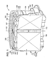
FIG. 1 is a perspective partial cross-sectional view of a first exemplary embodiment of the invention, in the form of a filter element, adapted for insertion into a filter housing, but not including the filter housing. -
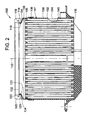
FIG. 2 is an orthographic cross section of the exemplary embodiment ofFIG. 1 . -
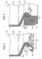
FIG. 3 is an orthographic partial cross section of an outwardly canted annular extension of a seal support frame of the exemplary embodiment ofFIGS. 1 and2 , with a seal member not shown, for clarity of illustration. -
FIG. 4 is an orthographic partial cross section of an outwardly canted annular extension of a seal support frame of the exemplary embodiment ofFIGS. 1-3 , that is identical toFIG. 3 , but with the seal member shown. -
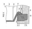
FIG. 5 is a schematic cross section, similar toFIGS. 3 and 4 , illustrating a method for molding the seal member onto the canted annular extension. -
FIGS. 6 and 7 are orthographic cross sections taken respectively through, and between, raised locating ribs of the seal support frame. -
FIG. 7 is a cross sectional view of a third exemplary embodiment of the invention in the form of a filter apparatus, according to the invention, including a filter assembly and a filter cartridge attached to the filter assembly. -
FIG. 8 is a partial cross sectional view cutting transversely through one of the raised ribs ofFIG. 6 , along line 8-8 ofFIG. 6 . -
FIG. 9 is a perspective illustration of a fluted filter media, used in exemplary embodiments of the invention. -
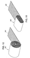
FIGS. 10 and 11 are perspective illustrations of optional cross sectional shapes for a filter pack, according to the invention. -
FIG. 12 is an orthographic cross section of a second exemplary embodiment of the invention, in the form of a filter apparatus including a filter housing and a filter element adapted for attachment to the filter housing. -
FIG. 13 is a partial orthographic cross section of an alternate embodiment of the invention, including an annular extension which is canted inward. - While the invention will be described in connection with certain preferred embodiments, there is no intent to limit it to those embodiments. On the contrary, the intent is to cover all alternatives, modifications and equivalents as included within the spirit and scope of the invention as defined by the appended claims.
-
FIGS. 1 and2 show a first exemplary embodiment of the invention in the form of afilter element 100, adapted for insertion into a filter housing, but not including the filter housing, for removing particulate matter from a flow of fluid passing through the filter housing. The term fluid as used herein is intended to include fluids in either liquid or gaseous forms. The exemplary embodiments shown herein specifically illustrate an air filter of the type used for filtering intake air for engines and air compressors. - The
filter element 100 includes afilter pack 102, aseal member 104, and aseal support frame 106 operatively connecting theseal member 104 to thefilter pack 102. Thefilter pack 102 includes first and second oppositely facingflow faces longitudinal axis 112 passing through the first andsecond flow faces seal support frame 106 including a cantedannular extension 114 thereof, projecting from thefirst flow face 108 at an oblique angle to thelongitudinal axis 112, for supporting theseal member 104. - The term "oblique," is used herein in accordance with the common dictionary meaning of that word to indicate that the canted
annular extension 114 extends at an angle, with respect to thelongitudinal axis 112, which is neither parallel nor perpendicular to thelongitudinal axis 112. The term "annular," is also used herein, according to its common dictionary definition, to describe a variety of ring-like shapes disposed about an axis or centerline. Annular shapes, as contemplated by the inventors, may include, but are not limited to, shapes that are round, rectangular, oval, or race-track-like with two generally straight and parallel sides joined by rounded ends. - In the
filter element 100 of the first exemplary embodiment, the canted annular extension includes afirst end 116 and adistal end 118 thereof, with thefirst end 116 of the cantedannular extension 114 being disposed nearer than thedistal end 118 thereof to both thelongitudinal axis 112 and thefirst flow face 108 of thefilter pack 102, such that the cantedannular extension 114 is canted outward from thelongitudinal axis 112. - The canted
annular extension 114 includes a plurality ofholes 120 extending therethrough, as best seen inFIG. 3 , with theseal member 104 including a portion thereof extending through theholes 120 in the cantedannular extension 114, as shown inFIG. 4 , to help retain theseal member 104 on the cantedannular extension 114. Theseal support frame 106 of thefilter element 100 also includes an inwardly canted intermediateannular segment 122 extending between thefirst end 116 of the cantedannular extension 114 and thefirst flow face 108 of thefilter pack 102, to thereby form a V-shaped, outwardly opening,annular groove 124 at the juncture of the cantedannular extension 106 and the inwardly canted intermediateannular segment 122, for receipt therein of aportion 126 of theseal member 104. - As shown in
FIG. 5 , theseal member 104 in thefilter element 100 is preferably formed from a material such as urethane foam, molded onto the cantedannular extension 114 using amold 128. During molding of theseal member 104, the filter element is placed into themold 128 with the cantedannular extension 114 facing downward, as shown inFIG. 5 . A material used for forming theseal member 114 is placed in themold 128 and allowed to foam and rise up around the cantedannular extension 114, and through theholes 120 into the V-shaped groove 124 of theseal support frame 106. The cantedannular extension 114 defines aninner surface 130 thereof, having a raisedannular rib 132 extending therefrom for contacting and sealing against themold 128, to thereby limit the extent of theseal member 104 along theinner surface 130 of the cantedannular extension 114. - As shown in
FIGS. 1 and2 , thefilter pack 102 defines anouter periphery 134 thereof, and the seal support frame includes an outerperipheral sidewall 136 thereof adapted for circumscribing theouter periphery 134 of thefilter pack 102. Theseal support frame 106 includes afirst end 138 thereof including the cantedannular extension 114, and asecond end 140 thereof, spaced from the first end thereof along thelongitudinal axis 112. Each of the first andsecond ends seal support frame 106 include a skirt section thereof, which are joined together to form the outerperipheral sidewall 136 of theseal support frame 106, and to define acavity 141 within theseal support frame 106 for receiving thefilter pack 102. The first andsecond ends second ends seal support frame 106 are joined to one another, thefilter pack 102 is retained within thecavity 141 of theseal support frame 106. - In the exemplary embodiment of the
filter element 100, the first andsecond ends seal support frame 106 are joined to one another and sealed to theouter periphery 134 of thefilter pack 106 by a single annular bead ofadhesive 142, as best seen inFIGS. 6 and 7 . The single annular bead ofadhesive 142 performs the dual functions of simultaneously joining the first andsecond ends seal support frame 106 to theouter periphery 134 of thefilter pack 106, and providing a seal blocking fluid flow between theouter periphery 134 of thefilter pack 102 and an inner surface of the peripheralannular sidewall 136. In other embodiments of the invention, more than one bead of sealant may be used, or one or more non-continuous beads of sealant may be used. It is contemplated, however, that use of a single annular bead ofadhesive 142 will generally be preferred, because the singleannular bead 142 performing multiple functions will typically facilitate manufacture and reduce costs, in most embodiments of the invention. - By virtue of the construction of the
seal support frame 106 of thefilter 100, the outerperipheral sidewall 136 includes afirst section 144 thereof extending from thefirst end 138 of theseal support frame 106, and terminating in adistal end 146 of thefirst section 144 of the outerperipheral sidewall 136. The outerperipheral sidewall 136 also includes asecond section 148 thereof, that extends from thesecond end 140 of theseal support frame 106 and terminates in adistal end 150 of thesecond section 148 of the outerperipheral sidewall 106. - The first and
second sections peripheral sidewall 136 are joined together with a joint formed by ahub 152 integrally formed with and extending from thedistal end 146 of thefirst section 144 of the outerperipheral sidewall 136, with thehub 152 being adapted for receiving thedistal end 150 of thesecond section 148 of the outerperipheral sidewall 136. Thehub 152 is configured such that aninner surface 154 of thehub 152, is spaced from thedistal end 150 of thesecond section 148 of the outerperipheral sidewall 136 to form a gap for receiving a portion of the bead ofadhesive 142. - As shown by
FIGS. 6-8 , in theseal support frame 106 of the exemplary embodiment of thefilter element 100, thesecond section 148 of the outerperipheral sidewall 136 includes a plurality of raisedribs 156 that extend outward from thesecond section 148 of the outerperipheral sidewall 136, adjacent thedistal end 150 of thesecond section 148 of the outerperipheral sidewall 136, for spacing theinner surface 154 of thehub 152 from thedistal end 150 of thesecond section 148 of the outerperipheral sidewall 136 of theseal support frame 106. Theribs 156 ensure that a gap of a predetermined size will be maintained between theinner surface 154 of thehub 152 and thedistal end 150 of thesecond section 148 of the outerperipheral sidewall 136 to allow a portion of the bead of adhesive 142 to remain in the gap when the first and second ends 138, 140 of theseal support frame 106 are joined to one another and to theouter periphery 134 of thefilter pack 102. - In the exemplary embodiment of the
filter element 100, theribs 156 also perform a second function, by being sized to provide a press fit of thedistal end 150 of thesecond section 148 of the outerperipheral sidewall 136 into thehub 152. The press fit allows theseal support frame 106 to be self-fixturing, to that once the first and second ends 138, 140 of theseal support frame 106 are pressed together to a desired height, the press fit will hold the first and second ends 138, 140 together at the desired height while the adhesive 142 is curing. This allows thefilter element 100 to be removed from any press equipment used for assembly, and set aside for curing of the adhesive, thereby freeing up the press equipment for use in assembling anotherfilter element 100. - The
hub 152, thedistal end 150 of thesecond section 148 of the outerperipheral side wall 136, and theouter periphery 134 of thefilter pack 102 are preferably joined to one another, after thefilter pack 102 is inserted into the portion thecavity 141 formed by thefirst end 138 of theseal support frame 106, by placing a single bead of adhesive 142, of a judiciously selected size, at the juncture of thedistal end 146 of thefirst section 144 of theperipheral sidewall 136 and thehub 152 and the outer periphery of thefilter pack 102, prior to inserting thedistal end 150 of thesecond section 148 of theperipheral sidewall 136 into thehub 152. After placement of the bead of adhesive 142 in thehub 152, thedistal end 150 of thesecond section 148 of theperipheral sidewall 136 is then inserted into thehub 152, and pressure is applied to thesecond end 140 of theseal support frame 106 to urge it into contact with thesecond face 110 of thefilter pack 102, and to push thedistal end 150 of thesecond section 148 into thehub 152. As thedistal end 150 of the second section of theperipheral sidewall 136 moves into thehub 152, the adhesive forming the single bead of adhesive 142 is squeezed into gaps between aninner surface 154 of thehub 152, that is spaced from thedistal end 150 of thesecond section 148 of the outerperipheral sidewall 136 to form a space for receiving an adhesive sealant for joining together the distal ends of the first and second sections of the outer peripheral sidewall. Once thedistal end 150 of thesecond section 148 of theperipheral sidewall 136 has been pressed far enough into thehub 152 to achieve a desired overall height of thefilter element 100, the press fit features described above allow thefilter element 100 to be self-fixturing while the adhesive 142 is curing. - The components of the
filter element 100 need not, however, be assembled in the same order, or by the method described above, in practicing the invention. It will be understood, by those having skill in the art, that in other embodiments of the invention, other arrangements, sequences, or methods may be used for forming and/or joining together component parts of a seal support frame, according to the invention. In other embodiments of the invention, for example, it may be desirable to have a filter pack captured within a seal support frame, according to the invention, but to not have the outer periphery joined to the seal support frame by an adhesive. It will also be understood that, although the outerperipheral sidewall 136 of theseal support frame 106 of the exemplary embodiment thefilter element 100 is imperforate, in other embodiments of the invention the outer peripheral sidewall may include one or more openings extending therethrough. - As shown in
FIG. 1 , the first and second ends 138, 140 of theseal support frame 106 of the exemplary embodiment of thefilter element 100 also respectively include a first endflow face screen 137 and a second endflow face screen 139, that provide protection against physical damage for the first and second flow faces 108, 110 of thefilter pack 102. The first and second flow face screens 137, 139 also serve to resist forces on thefilter pack 102 that are exerted in a direction parallel to thelongitudinal axis 112 by fluid flowing through thefilter pack 102. In the exemplary embodiment of thefilter element 100, the first and second flow face screens 137, 139 are formed integrally with theseal support frame 106. In other embodiments of the invention, however, such flow face screens may be separate components, attached to or held in place by the seal support frame, or may be eliminated. - Those having skill in the art will recognize that in embodiments of the invention having a canted annular extension, as described above, the canted extension provides a convoluted ring-like structure that is inherently stiff in the radial direction, for resisting compression forces imposed on the seal member when the filter element is inserted into a housing. As a result of this inherent stiffness, it is not necessary, in some embodiments of the invention, for the flow face screens 137, 139 to provide appreciable radial stiffening of the seal support.
- The
filter pack 102 of the exemplary embodiment of thefilter element 100 is formed from afilter media 157, as shown inFIG. 9 , that includes aconvoluted sheet 158 of porous filter material, for removing particulate matter from a fluid that is directed through thefilter element 100. Theconvoluted sheet 158 may be formed by any appropriate process, such as corrugating or pleating, but preferably by gathering, as described in a United States patent application, entitled "Gathered Filter Media and Method of Making Same," bearing the attorney docket no. 502854, assigned to the Assignee of the present invention, filed concurrently herewith and incorporated herein by reference. - The
convoluted sheet 158 of porous filter material, of thefilter media 157, forms a plurality of contiguousadjacent convolutions 160, commonly known in the industry as flutes. Selected ends of theflutes 160 of thefilter media 157 may be blocked, with a bead of adhesive for example, to cause fluid entering one end of some of theflutes 160 to flow through the porous filter media intoother flutes 160 prior to exiting thefilter media 157 at an opposite end of theflutes 160, in the manner known in the art. Selected flutes may also include anintermediate seal 161, as disclosed in a United States patent application, entitled "Fluted Filter Media with Intermediate Flow Restriction and Method of Making Same," bearing the attorney docket no. 502852, assigned to the Assignee of the present invention, filed concurrently herewith and incorporated herein by reference. - The
fluted filter media 157 of the exemplary embodiment of thefilter element 100 also includes aface sheet 162 attached to theconvoluted sheet 158, for retaining theconvoluted sheet 158 of porous filter material in a convoluted state. The term face sheet, as used herein, is intended to encompass any form of sheet or strip of generally flat, porous or non-porous, material attached to theconvoluted sheet 158 of porous filter material. In the exemplary embodiment, it is contemplated that theface sheet 162 would preferably be formed of a porous filter material, in most embodiments of the invention. - As shown in
FIG. 10 , thefilter pack 102 of the exemplary embodiment of thefilter element 100 described above, is formed by coiling thefilter media 157 to form a generally right-circular-cylinder-shaped structure, that is proportioned for insertion into a filter housing having a generally circular cross section. In other embodiments of the invention, however, a filter pack 102', and its associated filter element (not shown), may have a non-circular cross section, such as the race-track shaped filter shown inFIG. 11 . Filter packs having other cross sectional shapes, such as square, rectangular, or polygonal, for example, may also be utilized, in other embodiments of the invention, by coiling or bonding together successive layers of a fluted filter media. It is also understood that the invention is not limited to filter packs of fluted filter media. Those having skill in the art will readily recognize that the invention may also be practiced with efficacy, using other types of filter media. -
FIG. 12 shows a second exemplary embodiment of the invention, in the form of afilter apparatus 200, having afilter housing assembly 202 including afilter housing 204 and aboot 206, adapted for attachment thereto of afilter element 208. Thefilter element 208 is of the cartridge type described herein. In contrast to the first exemplary embodiment of the invention, however, in which the filter apparatus included only thefilter element 100, and not the filter assembly to which thefilter element 100 is adapted to be attached, the second exemplary embodiment of the invention includes both thefilter element 208 and thefilter assembly 202 formed by thehousing 204 and theboot 206. It should be further noted that thefilter apparatus 200 of the second exemplary embodiment also includes asafety filter 210, mounted in thefilter housing 204 at a point in the fluid flowpath downstream from thefilter cartridge 208. Other embodiments of a filter apparatus, according to the invention, may include fewer or more components than thefilter assembly 200 of the second exemplary embodiment. - The
filter element 208 of thefilter apparatus 200 is generally of the type described above in relation to the first exemplary embodiment. Specifically, thefilter element 208 of thefilter apparatus 200 includes a generally right-circular-cylinder shapedfilter pack 212 of fluted filter media, and aseal support frame 214 having an outwardly cantedannular extension 216 supporting aseal member 218 molded to the outwardly cantedextension 216, in the same manner as described above in relation to thefilter element 100 of the first exemplary embodiment. Theseal support frame 214 of thefilter element 208 of thefilter apparatus 200 of the second exemplary embodiment is also a two part structure including ahub arrangement 220 for joining anupper frame section 222 and a lower frame section 224 (as oriented inFIG. 12 ) together and to the outer periphery of the filter pack with a single annular bead of adhesive (not shown) in the same manner as described above in relation to the first exemplary embodiment of the invention. - Those having skill in the art will recognize that, although invention has been described herein with reference to several exemplary embodiments, many other embodiments of the invention are possible. For example, as shown in
FIG. 13 , in other embodiments of invention, afilter element 300 may include anannular extension 302 that is canted inward, rather than being canted outward as shown and described in relation to the first and second exemplary embodiments of the invention described above. Such an inwardly canted annular extension may or may not include through holes for receiving and retaining a portion of aseal member 304 molded, in situ, onto theannular extension 302. Those having skill in the art will recognize that having theannular extension 302 canted inward results in the distal end of theannular extension 302 having a smaller periphery than the portion of the annular extension adjacent theflow face 306 of thefilter pack 308. As a result of this construction, insertion and removal of thefilter element 300 is facilitated by having the compressive forces on theseal 304 be generally proportional to the axial engagement length of theseal member 304 with an inside wall of a housing (not shown). - As shown in
FIGS. 2 and13 , aseal member chamfer filter element - It is also contemplated that an embodiment of the invention including a seal support frame having an outer peripheral sidewall, adapted for circumscribing the outer periphery of the filter pack, a first end thereof including an annular extension, and a second end thereof spaced from the first end thereof along the longitudinal axis, with the first and second ends of the seal support frame joined by the outer peripheral sidewall of the seal support frame to define a cavity within the seal support frame for receiving the filter pack, may include an annular extension which is not canted either inward or outward.
Claims (7)
- A filter element adapted for insertion into a filter housing, but not including the filter housing, the filter element comprising:a filter pack (102), a seal member (104), (304), and a seal support frame (106) operatively connecting the seal member (104), (304) to the filter pack (102);the filter pack (102) having first and second oppositely facing flow faces (108), (110), and defining a longitudinal axis passing through the first and second flow faces (108), (110); andthe seal support frame (106) including a canted annular extension (114), (302) thereof, for supporting the seal member (104), (304), the canted annular extension (114), (302) projecting from one of the first and second flow faces (108), (110) of the filter pack (102) at an oblique angle to the longitudinal axis, and having a first end (116) and a distal end (118) thereof;the seal support frame (106) further including an inwardly canted intermediate annular segment (122) extending between the first end (116) of the canted annular extension (114), (302) and the one of the first and second flow faces (108), (110) of the filter pack (102), to thereby form a V-shaped, outwardly opening, annular groove (124) at the juncture of the canted annular extension (114), (302) and the inwardly canted intermediate annular segment (122).
- The filter element of claim 1, wherein the filter pack (102) includes a fluted filter media (157) having a plurality of flutes (160) of porous filter material.
- The filter element of any preceding claim, wherein the distal end (118) of the canted annular extension (302) is disposed nearer than the first end (116) thereof to the longitudinal axis, such that the canted annular extension (114) is canted inward with respect to the longitudinal axis.
- The filter element of any of claims 1 or 2, wherein the first end (116) of the canted annular extension (114) is disposed nearer than the distal end (118) thereof to the longitudinal axis, such that the canted annular extension (114) is canted outward from the longitudinal axis.
- The filter element of any preceding claim, wherein the canted annular extension (114), (302) includes one or more holes (120) extending therethrough, and the seal member (104), (304) includes a portion thereof extending through one or more of the one or more holes (120) in the canted annular extension (114), (302).
- The filter element of any preceding claim, wherein the seal member (104), (304) is molded onto the canted annular extension (114), (302) using a mold (128), and the canted annular extension (114), (302) defines an inner surface (130) thereof having a raised annular rib (132) extending therefrom for contacting and sealing against the mold (128), to thereby limit the extent of the seal member (104), (304) along the inner surface (130) of the canted annular extension (114), (302).
- The filter element of any preceding claim, wherein a portion of the seal member (104), (304) extends into the V-shaped annular groove (124).
Applications Claiming Priority (2)
| Application Number | Priority Date | Filing Date | Title |
|---|---|---|---|
| US10/979,876 US7318851B2 (en) | 2004-11-02 | 2004-11-02 | Filter element |
| PCT/US2005/032256 WO2006049701A1 (en) | 2004-11-02 | 2005-09-09 | Filter element with canted seal support |
Publications (2)
| Publication Number | Publication Date |
|---|---|
| EP1812138A1 EP1812138A1 (en) | 2007-08-01 |
| EP1812138B1 true EP1812138B1 (en) | 2013-07-17 |
Family
ID=35478874
Family Applications (1)
| Application Number | Title | Priority Date | Filing Date |
|---|---|---|---|
| EP05795564.3A Active EP1812138B1 (en) | 2004-11-02 | 2005-09-09 | Filter element with canted seal support |
Country Status (7)
| Country | Link |
|---|---|
| US (5) | US7318851B2 (en) |
| EP (1) | EP1812138B1 (en) |
| JP (1) | JP4794566B2 (en) |
| AU (1) | AU2005301266B2 (en) |
| CA (1) | CA2585961C (en) |
| MX (1) | MX2007005239A (en) |
| WO (1) | WO2006049701A1 (en) |
Cited By (1)
| Publication number | Priority date | Publication date | Assignee | Title |
|---|---|---|---|---|
| US10702821B2 (en) | 2016-05-03 | 2020-07-07 | Mann+Hummel Gmbh | Annular filter element, in particular for gas filtration, and filter device |
Families Citing this family (78)
| Publication number | Priority date | Publication date | Assignee | Title |
|---|---|---|---|---|
| AU722679B2 (en) * | 1996-04-26 | 2000-08-10 | Donaldson Company Inc. | Fluted filter media |
| US6966940B2 (en) | 2002-04-04 | 2005-11-22 | Donaldson Company, Inc. | Air filter cartridge |
| KR20050098922A (en) | 2003-02-11 | 2005-10-12 | 도널드선 컴파니 인코포레이티드 | Air cleaner arrangements; serviceable filter elements;and,method |
| EP1608453B1 (en) | 2003-03-18 | 2010-06-02 | Donaldson Company, Inc. | Improved process for coiling z-filter media |
| US20090266041A1 (en) * | 2003-12-22 | 2009-10-29 | Donaldson Company, Inc. | Seal arrangement for filter element; Filter element assembly; and, methods |
| WO2007056589A2 (en) * | 2005-11-09 | 2007-05-18 | Donaldson Company, Inc. | Seal arrangement for filter element; filter element assembly: and, methods |
| CN101693158B (en) * | 2003-12-22 | 2013-02-20 | 唐纳森公司 | Filter element comprising a seal arrangement and method for making the same |
| EP2679293A1 (en) | 2004-03-24 | 2014-01-01 | Donaldson Company, Inc. | Air Cleaner |
| GB0409548D0 (en) * | 2004-04-29 | 2004-06-02 | King S College London | Robotic hand |
| CN102258918B (en) | 2004-04-30 | 2016-02-24 | 唐纳森公司 | Filtration device structure; Shell; Assembly and method |
| US7905936B2 (en) | 2004-04-30 | 2011-03-15 | Donaldson Company, Inc. | Filter arrangements; housing; assemblies; and, methods |
| US8048188B2 (en) | 2004-06-18 | 2011-11-01 | Donaldson Company, Inc. | Air cleaner arrangements; serviceable filter cartridge; and, methods |
| WO2006012386A2 (en) | 2004-07-20 | 2006-02-02 | Donaldson Company, Inc. | Z-filter media pack arrangement; filter cartridge; air cleaner arrangement; and, methods |
| US20060091064A1 (en) * | 2004-11-02 | 2006-05-04 | Baldwin Filters, Inc. | Filter apparatus with separable seal support frame |
| US20070186528A1 (en) * | 2006-02-15 | 2007-08-16 | Baldwin Filters, Inc. | Fluted filter apparatus |
| US7318851B2 (en) | 2004-11-02 | 2008-01-15 | Baldwin Filters, Inc. | Filter element |
| US20110197556A1 (en) * | 2004-11-02 | 2011-08-18 | Baldwin Filters, Inc. | Filter element |
| US20060091061A1 (en) * | 2004-11-02 | 2006-05-04 | Baldwin Filters, Inc. | Filter assembly with sealing system |
| US7931725B2 (en) | 2004-11-02 | 2011-04-26 | Baldwin Filters, Inc. | Fluted filter apparatus |
| US7909954B2 (en) * | 2004-11-03 | 2011-03-22 | Baldwin Filters, Inc. | Method and apparatus for winding a filter media pack |
| US7569090B2 (en) | 2004-11-12 | 2009-08-04 | Donaldson Company, Inc. | Method of forming filter arrangements; and, apparatus |
| DE102005029750A1 (en) * | 2005-06-24 | 2006-12-28 | Mann + Hummel Gmbh | Filter sealing system |
| DE202005010445U1 (en) * | 2005-06-30 | 2006-11-16 | Mann + Hummel Gmbh | Filter arrangement for liquids |
| DE102005031058A1 (en) * | 2005-07-02 | 2007-01-04 | Mahle International Gmbh | Filter element and a filter housing suitable for receiving it |
| KR101540897B1 (en) | 2005-10-11 | 2015-07-30 | 도날드슨 컴파니, 인코포레이티드 | Air filter arrangement, assembly, and methods |
| DE102006001126A1 (en) | 2006-01-09 | 2007-07-12 | Kettenbach Gmbh & Co. Kg | Dental impression compounds, hardened products prepared therefrom and use of surfactants for the production of dental impression compounds |
| WO2007084689A2 (en) * | 2006-01-20 | 2007-07-26 | Donaldson Company, Inc. | Air cleaner configured for receipt of various sized filter cartridges; components thereof; and, methods |
| US7992722B2 (en) * | 2006-01-27 | 2011-08-09 | Cummins Filtration Ip, Inc. | Radial seal filter with multi-component housing |
| DE202006001440U1 (en) * | 2006-01-31 | 2007-06-14 | Mann+Hummel Gmbh | Filter element and filter system, in particular for the intake air of an internal combustion engine |
| US7753982B2 (en) | 2006-02-17 | 2010-07-13 | Baldwin Filters, Inc. | Filter with drained jacket, seal indicator/lock means, and seal baffle |
| DE102006025232A1 (en) * | 2006-05-29 | 2008-01-10 | Mann + Hummel Gmbh | filter housing |
| JP2009541643A (en) * | 2006-06-22 | 2009-11-26 | ドナルドソン カンパニー,インコーポレイティド | AIR CLEANER COMPOSITION, ITS COMPONENT, AND ITS MANUFACTURING METHOD |
| US7713321B2 (en) * | 2006-06-22 | 2010-05-11 | Donaldson Company, Inc. | Air cleaner arrangements; components thereof; and, methods |
| US10040020B2 (en) | 2006-12-06 | 2018-08-07 | Baldwin Filters, Inc. | Fluid filter apparatus having filter media wound about a winding frame |
| US9757676B2 (en) | 2006-12-06 | 2017-09-12 | Baldwin Filters, Inc. | Method and apparatus for winding a filter element |
| WO2009033040A1 (en) | 2007-09-07 | 2009-03-12 | Donaldson Company, Inc. | Air filter assembly; components thereof; and, methods |
| DE202007014822U1 (en) * | 2007-10-02 | 2009-02-19 | Mann+Hummel Gmbh | Filter element Zackendichtung |
| DE202007013822U1 (en) * | 2007-10-02 | 2009-02-19 | Mann+Hummel Gmbh | Filter element and filter system |
| DE202007014821U1 (en) * | 2007-10-02 | 2009-02-26 | Mann+Hummel Gmbh | Filter element V-seal |
| US9545593B2 (en) * | 2007-11-01 | 2017-01-17 | Baldwin Filters, Inc. | Winding core pressure relief for fluted filter |
| US8048187B2 (en) | 2008-06-30 | 2011-11-01 | Baldwin Filters, Inc. | Filter frame attachment and fluted filter having same |
| US7959703B2 (en) * | 2008-06-30 | 2011-06-14 | Baldwin Filters, Inc. | Fluted filter with integrated frame |
| CA2731225C (en) * | 2008-07-22 | 2018-04-03 | Donaldson Company, Inc. | Air cleaner assembly and components therefor |
| US8491684B2 (en) * | 2009-02-27 | 2013-07-23 | Donaldson Company, Inc. | Filter cartridge; components thereof; and methods |
| US8506668B2 (en) | 2009-03-30 | 2013-08-13 | Baldwin Filters, Inc. | Fluted filter with axial seal |
| US8128719B1 (en) | 2009-08-21 | 2012-03-06 | Cummins Filtration Ip Inc. | Filter element with percussion band |
| DE102009056511A1 (en) * | 2009-12-02 | 2011-06-09 | Mann+Hummel Gmbh | Filter element and method of making a filter element |
| DE102009060214A1 (en) * | 2009-12-23 | 2011-06-30 | MAHLE International GmbH, 70376 | Filter element and manufacturing process |
| WO2011115979A2 (en) | 2010-03-17 | 2011-09-22 | Baldwin Filters, Inc. | Fluid filter |
| WO2011115973A2 (en) | 2010-03-17 | 2011-09-22 | Baldwin Filters, Inc. | Fluid filter |
| US8590158B2 (en) | 2010-10-29 | 2013-11-26 | Corning Incorporated | Methods of making filter apparatus and fabricating a porous ceramic article |
| US8591622B2 (en) | 2010-10-29 | 2013-11-26 | Corning Incorporated | Filter apparatus with porous ceramic plates |
| CN102380272A (en) * | 2011-11-03 | 2012-03-21 | 长春科德宝·宝翎滤清器有限公司 | Filter element and method for manufacturing same |
| DE102012005731B4 (en) * | 2012-03-23 | 2017-07-06 | Mann + Hummel Gmbh | Air filter and filter element of an air filter |
| BR112015001748B1 (en) | 2012-07-25 | 2022-03-15 | Baldwin Filters, Inc | filter set |
| US20140208705A1 (en) * | 2013-01-25 | 2014-07-31 | Baldwin Filters, Inc. | Mutli-Pass Fluted Filter |
| US9724635B2 (en) * | 2013-03-14 | 2017-08-08 | Bladwin Filters, Inc. | Rectangular stacked fluted filter cartridge |
| EP3055547A4 (en) * | 2013-10-02 | 2017-07-26 | Clarcor Engine Mobile Solutions, LLC | Fuel filter cartridge and method of use thereof |
| US10159778B2 (en) | 2014-03-24 | 2018-12-25 | Fenwal, Inc. | Biological fluid filters having flexible walls and methods for making such filters |
| US9968738B2 (en) | 2014-03-24 | 2018-05-15 | Fenwal, Inc. | Biological fluid filters with molded frame and methods for making such filters |
| US10376627B2 (en) | 2014-03-24 | 2019-08-13 | Fenwal, Inc. | Flexible biological fluid filters |
| US9796166B2 (en) | 2014-03-24 | 2017-10-24 | Fenwal, Inc. | Flexible biological fluid filters |
| US9782707B2 (en) | 2014-03-24 | 2017-10-10 | Fenwal, Inc. | Biological fluid filters having flexible walls and methods for making such filters |
| DE112015004116B4 (en) * | 2014-09-09 | 2024-02-01 | Cummins Filtration Ip, Inc. | Axial flow air filter element, filter system and filter system maintenance procedures |
| WO2016044293A1 (en) * | 2014-09-15 | 2016-03-24 | Donaldson Company, Inc. | Filter cartridges; air cleaner assemblies; housings; features; components; and, methods |
| US11278833B2 (en) | 2015-08-17 | 2022-03-22 | Parker-Hamilton Corporation | Filter media packs, methods of making, and ultrasonic cutting or welding |
| EP3777989A1 (en) | 2015-08-17 | 2021-02-17 | Parker-Hannificn Corporation | Filter media packs, methods of making and filter media presses |
| USD798907S1 (en) | 2015-11-20 | 2017-10-03 | Baldwin Filters, Inc. | Filter element |
| EP3377751B1 (en) * | 2015-11-20 | 2020-09-09 | Baldwin Filters, Inc. | Filter element having mounting frame |
| EP3377750B1 (en) | 2015-11-20 | 2022-04-13 | Baldwin Filters, Inc. | Filter media pack with porous wrapper |
| US10682597B2 (en) | 2016-04-14 | 2020-06-16 | Baldwin Filters, Inc. | Filter system |
| CA3049263A1 (en) | 2017-02-16 | 2018-08-23 | Jason Lamarr Tate | Filter media packs, methods of making, and ultrasonic cutting or welding |
| TWI655025B (en) * | 2018-01-24 | 2019-04-01 | 淳靖股份有限公司 | Filter element frame, filter element and gluing method of filter element |
| US10940423B2 (en) | 2018-04-19 | 2021-03-09 | Ingersoll-Rand Industrial U.S., Inc. | Compressor system and filter housing |
| DE112019004484B4 (en) | 2018-09-07 | 2023-12-21 | Parker-Hannifin Corporation | Air filter media manufacturing method and tool therefor and system for forming geometry in a filter media web. |
| WO2020081324A1 (en) | 2018-10-16 | 2020-04-23 | Parker-Hannifin Corporation | Pleated channel flow filter and/or roll form method |
| DE112019005928T5 (en) | 2018-11-28 | 2021-09-30 | Cummins Filtration Ip, Inc. | CURVED SEAL ON FILTER ELEMENT AND PROTECTIVE SEAL FORM |
| WO2020231769A1 (en) | 2019-05-14 | 2020-11-19 | Cummins Filtration Ip, Inc. | Curved lobed seal lock air filter system |
Family Cites Families (158)
| Publication number | Priority date | Publication date | Assignee | Title |
|---|---|---|---|---|
| US1700126A (en) | 1926-06-17 | 1929-01-29 | American Kreuger & Toll Corp | Filter medium for air and gases |
| US1947066A (en) | 1932-12-14 | 1934-02-13 | Samuel M Langston Co | Corrugator |
| US1954881A (en) | 1933-03-23 | 1934-04-17 | Samuel M Langston Co | Corrugator |
| US1943080A (en) | 1933-04-21 | 1934-01-09 | Samuel M Langston | Corrugator |
| US3025963A (en) * | 1958-03-13 | 1962-03-20 | Russell H Curtis | Products useful as filtering devices and methods of making them |
| US3255889A (en) | 1961-04-10 | 1966-06-14 | American Mach & Foundry | Wound filter |
| SE302235B (en) | 1966-02-08 | 1968-07-08 | Svenska Flaektfabriken Ab | |
| GB1121896A (en) * | 1966-07-21 | 1968-07-31 | Gen Motors Ltd | Air filters |
| US3676247A (en) | 1969-02-03 | 1972-07-11 | Australian Paper Manufacturers | Corrugating paperboard |
| US3679057A (en) | 1970-09-11 | 1972-07-25 | Damasco Rodolfo Adelto Perez | Screen filter pack and method for making same |
| SE409948B (en) | 1976-03-16 | 1979-09-17 | Nederman Bill P Ph | FILTER DEVICE FOR SEPARATION OF SOLID PARTICLES FROM GASES, SPECIAL WELDING GASES |
| US4253228A (en) | 1978-09-14 | 1981-03-03 | Filterspun, Inc. | Apparatus and system for forming wound filters |
| US4252591A (en) | 1979-05-02 | 1981-02-24 | Pall Corporation | Corrugating apparatus and process |
| US4257790A (en) | 1979-10-10 | 1981-03-24 | Henningsen Foods, Inc. | Quick change filter bag arrangement |
| DE2947080A1 (en) | 1979-11-22 | 1981-05-27 | Delbag-Luftfilter Gmbh, 1000 Berlin | Air filter cell - made from two pieces of cardboard and filter material |
| DE3280289D1 (en) * | 1981-02-23 | 1991-02-14 | Nippon Denso Co | FILTER ELEMENT FOR FLUID CLEANING SYSTEMS. |
| GB2103106B (en) | 1981-04-28 | 1985-07-10 | Kleen Air Maintenance Services | Air filter |
| US4410427A (en) * | 1981-11-02 | 1983-10-18 | Donaldson Company, Inc. | Fluid filtering device |
| US4579698A (en) | 1982-05-28 | 1986-04-01 | Amf, Inc. | Process for producing a microporous polymeric filter membrane with adjacent non-porous edge layers and a pleated filter element formed from the membrane |
| GB8329395D0 (en) | 1983-11-03 | 1983-12-07 | Ciba Geigy Ag | Photopolymerisable compositions |
| JPS60112320A (en) | 1983-11-24 | 1985-06-18 | Hitachi Ltd | Protecting system of tristate gate |
| SE452598B (en) | 1985-06-20 | 1987-12-07 | Flodins Filter Ab | PROCEDURE AND DEVICE FOR FILTER MANUFACTURING |
| USH556H (en) | 1985-12-02 | 1988-12-06 | Method of manufacture and machine for manufacturing subterranean wall drain | |
| US4747944A (en) | 1986-04-29 | 1988-05-31 | Midwest Conservation Specialties, Inc. | Recirculating filter system |
| US4720292B1 (en) * | 1986-07-14 | 1991-09-10 | Cylindrical air filter with lightweight housing and radially directed seal | |
| GB8621660D0 (en) | 1986-09-09 | 1986-10-15 | Domnick Hunter Filters Ltd | Filter element |
| JPS63122617A (en) | 1986-11-13 | 1988-05-26 | Lion Corp | Skin cleaning agent |
| SE455378B (en) | 1986-11-17 | 1988-07-11 | Flodins Filter Ab | PROCEDURE FOR MANUFACTURING FILTERS |
| JPH0231131A (en) | 1988-07-20 | 1990-02-01 | Rigaku Keisoku Kk | Method of industrial analysis of coal and infrared heating oven |
| DE8810295U1 (en) | 1988-08-13 | 1988-10-13 | Stanelle, Karl-Heinz, 7129 Gueglingen, De | |
| US5346675A (en) | 1988-12-16 | 1994-09-13 | Usui Kokusai Sangyo Kabushiki Kaisha | Exhaust gas cleaning apparatus |
| US4976857A (en) | 1989-05-03 | 1990-12-11 | Newport Filters, Inc. | Filter element and fabrication methodology |
| US5238474A (en) * | 1990-10-19 | 1993-08-24 | Donaldson Company, Inc. | Filtration arrangement |
| US5213275A (en) | 1991-07-17 | 1993-05-25 | General Dynamics Corporation, Space Systems Division | Reeding edge for securing in place fiber band during filament winding operation |
| US5245897A (en) | 1991-11-25 | 1993-09-21 | E. I. Du Pont De Nemours And Company | System and method for advancing the leading edge of a corrugated web |
| EP0558872B1 (en) | 1992-03-04 | 1996-08-28 | Ciba-Geigy Ag | Method and apparatus for winding of windable substrates |
| JP3239517B2 (en) | 1992-06-17 | 2001-12-17 | 株式会社デンソー | Manufacturing method of filtration element |
| DE4223723C2 (en) | 1992-07-18 | 1996-08-29 | Mann & Hummel Filter | Method and device for producing a zigzag folded filter |
| DE9305767U1 (en) * | 1993-04-16 | 1993-06-17 | Filterwerk Mann & Hummel Gmbh, 7140 Ludwigsburg, De | |
| JP3362453B2 (en) | 1993-05-21 | 2003-01-07 | 株式会社デンソー | Filtration element |
| US5484466A (en) * | 1994-02-14 | 1996-01-16 | Baldwin Filters, Inc. | Air filter element with radial seal sealing gasket |
| SE506017C2 (en) | 1994-05-10 | 1997-11-03 | Volvo Ab | Air Filter |
| WO1995035202A1 (en) | 1994-06-21 | 1995-12-28 | Miller Ray R | Method of bonding laminates and resulting laminates |
| US5588945A (en) | 1995-02-21 | 1996-12-31 | Corrugated Gear & Services, Inc. | Method and device for spacing a corrugating finger relative to a corrugating roll |
| US5685985A (en) * | 1995-12-20 | 1997-11-11 | Baldwin Filters, Inc. | Environmentally friendly filter cartridge |
| DE19654188C5 (en) * | 1995-12-26 | 2010-09-23 | Toyoda Boshoku Corp., Kariya-shi | Filter element and method for its production |
| US5792242A (en) | 1996-02-26 | 1998-08-11 | Minnesota Mining And Manufacturing Co. | Electrostatic fibrous filter web |
| AU722679B2 (en) | 1996-04-26 | 2000-08-10 | Donaldson Company Inc. | Fluted filter media |
| US5895574A (en) * | 1996-04-26 | 1999-04-20 | Donaldson Company, Inc. | Rolled liquid filter using fluted media |
| US5792247A (en) * | 1996-04-26 | 1998-08-11 | Donaldson Company, Inc. | Integrated resonator and filter apparatus |
| US5902364A (en) * | 1996-04-26 | 1999-05-11 | Donaldson Company, Inc. | Conical filter |
| US5772883A (en) | 1996-04-26 | 1998-06-30 | Donaldson Company, Inc. | Slanted inline filter |
| US5820646A (en) * | 1996-04-26 | 1998-10-13 | Donaldson Company, Inc. | Inline filter apparatus |
| US6022305A (en) | 1998-03-11 | 2000-02-08 | Aaf International | Pleating apparatus |
| ATE220657T1 (en) * | 1998-11-04 | 2002-08-15 | Rohm & Haas | METHOD FOR PRODUCING HIGH YIELD METHYL METHACRYLATE OR METHACRYLIC ACID |
| US6190432B1 (en) | 1999-02-26 | 2001-02-20 | Donaldson Company, Inc. | Filter arrangement; sealing system; and methods |
| US6235195B1 (en) * | 1999-02-26 | 2001-05-22 | Donaldson Company, Inc. | Filter element incorporating a handle member |
| US6179890B1 (en) * | 1999-02-26 | 2001-01-30 | Donaldson Company, Inc. | Air cleaner having sealing arrangement between media arrangement and housing |
| US6221122B1 (en) * | 1999-02-26 | 2001-04-24 | Donaldson Company, Inc. | Filter element and methods |
| USD450827S1 (en) | 1999-02-26 | 2001-11-20 | Donaldson Company, Inc. | Filter element having sealing system |
| US6210469B1 (en) | 1999-02-26 | 2001-04-03 | Donaldson Company, Inc. | Air filter arrangement having first and second filter media dividing a housing and methods |
| USD461003S1 (en) | 1999-02-26 | 2002-07-30 | Donaldson Company, Inc. | Filter element having sealing system |
| CA2360445C (en) | 1999-02-26 | 2011-01-25 | Donaldson Company, Inc. | Filter arrangement; sealing system; and methods |
| DE19935297A1 (en) * | 1999-07-27 | 2001-02-01 | Mahle Filtersysteme Gmbh | Filter body of a fluid filter, especially an air filter |
| USD437402S1 (en) | 1999-11-05 | 2001-02-06 | Donaldson Company, Inc. | Filter element with centerpiece |
| US6348084B1 (en) | 1999-11-05 | 2002-02-19 | Donaldson Company, Inc. | Filter element, air cleaner, and methods |
| US6348085B1 (en) | 1999-11-10 | 2002-02-19 | Donaldson Company, Inc. | Filter arrangement and methods |
| US6416605B1 (en) | 1999-11-24 | 2002-07-09 | Donaldson Company, Inc. | Method for manufacturing fluted media |
| US6436162B1 (en) | 2000-03-22 | 2002-08-20 | Nelson Industries, Inc. | Twist and lock filter housing with anti-rotation stop |
| DE10023427A1 (en) | 2000-05-12 | 2001-11-15 | Mann & Hummel Filter | Liquid filter comprises housing which holds filter cartridge, lid, and inlet and outlet |
| US6946012B1 (en) | 2000-05-18 | 2005-09-20 | Fleetguard, Inc. | Filter and forming system |
| US6368374B1 (en) | 2000-06-13 | 2002-04-09 | Donaldson Company, Inc. | Filter arrangement and methods |
| USD450828S1 (en) | 2000-06-13 | 2001-11-20 | Donaldson Company, Inc. | Fluted filter element having a handle |
| US6743273B2 (en) | 2000-09-05 | 2004-06-01 | Donaldson Company, Inc. | Polymer, polymer microfiber, polymer nanofiber and applications including filter structures |
| US6673136B2 (en) | 2000-09-05 | 2004-01-06 | Donaldson Company, Inc. | Air filtration arrangements having fluted media constructions and methods |
| US6402798B1 (en) | 2000-09-19 | 2002-06-11 | Nelson Industries, Inc. | Twist and lock filter housing with nontorsional anti-rotation stop |
| US6511599B2 (en) | 2000-12-18 | 2003-01-28 | Nelson Industries, Inc. | Multi-element cylindrical filter with equalized flow |
| US6743317B2 (en) * | 2000-12-19 | 2004-06-01 | Robert M. Wydeven | Method of sealing, housing and constructing honeycomb filters |
| US6447567B1 (en) * | 2001-05-14 | 2002-09-10 | Baldwin Filters, Inc. | Air filter element with integral radial seal gasket |
| RU2300543C2 (en) | 2001-05-31 | 2007-06-10 | Дональдсон Компани, Инк. | Fine fiber compositions, methods for preparation thereof, and a method of manufacturing fine-fiber material |
| USD460169S1 (en) | 2001-06-06 | 2002-07-09 | Donaldson Company Inc. | Filter element having an inlet grid |
| US6852141B2 (en) | 2001-06-06 | 2005-02-08 | Donaldson Company, Inc. | Filter element having center piece and methods |
| US6517598B2 (en) * | 2001-06-06 | 2003-02-11 | Donaldson Company, Inc. | Filter element having flange and methods |
| US6610126B2 (en) | 2001-06-06 | 2003-08-26 | Donaldson Company, Inc. | Filter element having sealing members and methods |
| DE10152552A1 (en) * | 2001-10-24 | 2003-05-08 | Mann & Hummel Filter | Filter element, in particular for the filtration of liquids |
| ATE472359T1 (en) | 2001-12-03 | 2010-07-15 | Donaldson Co Inc | FILTER ELEMENTS WITH FOLDED FILTER MEDIA |
| USD473637S1 (en) | 2001-12-03 | 2003-04-22 | Donaldson Company, Inc. | Fluted filter element |
| USD483459S1 (en) | 2002-01-23 | 2003-12-09 | Donaldson Company, Inc. | Air filter element for engine |
| US6966940B2 (en) * | 2002-04-04 | 2005-11-22 | Donaldson Company, Inc. | Air filter cartridge |
| US6851569B2 (en) | 2002-04-22 | 2005-02-08 | Plastican, Inc. | Reusable lid and container |
| JP4344687B2 (en) * | 2002-05-09 | 2009-10-14 | ドナルドソン カンパニー,インコーポレイティド | Air filter having fluted filter media |
| US7168573B2 (en) | 2002-06-07 | 2007-01-30 | Baldwin Filters, Inc. | Environmentally friendly filter cartridge |
| DE10227050B3 (en) | 2002-06-17 | 2004-01-29 | Albert Frey Verpackungsentwicklungen Und Vertriebs-Gmbh | Corrugated cardboard with tear line |
| WO2004007054A1 (en) | 2002-07-10 | 2004-01-22 | Donaldson Company, Inc. | Fluted filter medium and process for its manufacture |
| US6703675B1 (en) | 2002-08-20 | 2004-03-09 | Memx, Inc. | Particle filter for partially enclosed microelectromechanical systems |
| US6959819B2 (en) | 2002-10-08 | 2005-11-01 | Pti Technologies, Inc. | Fatigue rated glass filled plastic filter assembly incorporating a coreless plastic filter element with integral seal |
| US7282075B2 (en) | 2002-12-11 | 2007-10-16 | Donaldson Company, Inc. | Z-filter media with reverse-flow cleaning systems and methods |
| US6887343B2 (en) | 2002-12-20 | 2005-05-03 | Fleetguard, Inc. | Filter coating, winding, finishing and manufacturing system |
| USD484584S1 (en) | 2003-01-22 | 2003-12-30 | Donaldson Company, Inc. | Filter element for engine |
| KR20050098922A (en) | 2003-02-11 | 2005-10-12 | 도널드선 컴파니 인코포레이티드 | Air cleaner arrangements; serviceable filter elements;and,method |
| EP1608453B1 (en) | 2003-03-18 | 2010-06-02 | Donaldson Company, Inc. | Improved process for coiling z-filter media |
| US7300486B1 (en) | 2003-04-02 | 2007-11-27 | Wix Filtration Corp Llc | Filter elements having injection molded thermoplastic seals and methods of making same |
| US7008465B2 (en) | 2003-06-19 | 2006-03-07 | Donaldson Company, Inc. | Cleanable high efficiency filter media structure and applications for use |
| US7458468B2 (en) | 2003-08-05 | 2008-12-02 | Purolator Filters Na Llc | Fuel filter diverter |
| WO2005040593A1 (en) | 2003-10-17 | 2005-05-06 | Donaldson Company, Inc. | Precleaner arrangement for use in air filtration, method of operation of precleaner and air cleaner comprising the precleaner arrangement |
| WO2005046841A1 (en) | 2003-11-12 | 2005-05-26 | Donaldson Company, Inc. | Air filter with a slide mount for filtering element |
| WO2005058461A1 (en) | 2003-12-16 | 2005-06-30 | Donaldson Company, Inc. | Air cleaner arrangement and methods |
| US20090266041A1 (en) | 2003-12-22 | 2009-10-29 | Donaldson Company, Inc. | Seal arrangement for filter element; Filter element assembly; and, methods |
| CN101693158B (en) | 2003-12-22 | 2013-02-20 | 唐纳森公司 | Filter element comprising a seal arrangement and method for making the same |
| WO2007056589A2 (en) | 2005-11-09 | 2007-05-18 | Donaldson Company, Inc. | Seal arrangement for filter element; filter element assembly: and, methods |
| WO2005082484A1 (en) | 2004-02-09 | 2005-09-09 | Donaldson Company, Inc. | Pleated corrugated filter media |
| WO2005077487A1 (en) | 2004-02-10 | 2005-08-25 | Donaldson Company, Inc. | Media arrangement; filter constructions; and, methods |
| US7682416B2 (en) | 2004-02-17 | 2010-03-23 | Donaldson Company, Inc. | Air cleaner arrangements; serviceable filter elements; and, methods |
| USD506539S1 (en) | 2004-03-24 | 2005-06-21 | Donaldson Company, Inc. | Filter cartridge |
| EP2679293A1 (en) | 2004-03-24 | 2014-01-01 | Donaldson Company, Inc. | Air Cleaner |
| US7905936B2 (en) | 2004-04-30 | 2011-03-15 | Donaldson Company, Inc. | Filter arrangements; housing; assemblies; and, methods |
| EP1768761B1 (en) | 2004-06-08 | 2010-11-03 | Donaldson Company, Inc. | Z-filter media pack arrangement |
| WO2005123222A1 (en) | 2004-06-14 | 2005-12-29 | Donaldson Company, Inc. | Air filter arrangement; assembly; and, methods |
| US8048188B2 (en) | 2004-06-18 | 2011-11-01 | Donaldson Company, Inc. | Air cleaner arrangements; serviceable filter cartridge; and, methods |
| WO2006012386A2 (en) | 2004-07-20 | 2006-02-02 | Donaldson Company, Inc. | Z-filter media pack arrangement; filter cartridge; air cleaner arrangement; and, methods |
| WO2006014941A2 (en) | 2004-07-26 | 2006-02-09 | Donaldson Company, Inc. | Z-filter media pack arrangement; and, methods |
| JP5032989B2 (en) | 2004-08-06 | 2012-09-26 | ドナルドソン カンパニー,インコーポレイティド | Air filter structure, assembly and method |
| US20060091061A1 (en) * | 2004-11-02 | 2006-05-04 | Baldwin Filters, Inc. | Filter assembly with sealing system |
| US7318851B2 (en) | 2004-11-02 | 2008-01-15 | Baldwin Filters, Inc. | Filter element |
| US7931725B2 (en) | 2004-11-02 | 2011-04-26 | Baldwin Filters, Inc. | Fluted filter apparatus |
| US20110197556A1 (en) | 2004-11-02 | 2011-08-18 | Baldwin Filters, Inc. | Filter element |
| US8042694B2 (en) * | 2004-11-02 | 2011-10-25 | Baldwin Filters, Inc. | Gathered filter media for an air filter and method of making same |
| US20060090431A1 (en) | 2004-11-02 | 2006-05-04 | Baldwin Filters, Inc. | Filter assembly with combination filter element |
| US20060091064A1 (en) * | 2004-11-02 | 2006-05-04 | Baldwin Filters, Inc. | Filter apparatus with separable seal support frame |
| US20070186528A1 (en) | 2006-02-15 | 2007-08-16 | Baldwin Filters, Inc. | Fluted filter apparatus |
| US20060091084A1 (en) * | 2004-11-02 | 2006-05-04 | Baldwin Filters, Inc. | Fluted filter media with intermediate flow restriction and method of making same |
| US7255300B2 (en) | 2004-11-03 | 2007-08-14 | Baldwin Filters, Inc. | Method and apparatus for winding a filter media pack |
| EP1838407B1 (en) | 2004-12-29 | 2018-04-04 | Baldwin Filters, Inc. | Filter with improved fatigue performance and torque transfer |
| US7656441B2 (en) * | 2005-01-05 | 2010-02-02 | Eastman Kodak Company | Hue correction for electronic imagers |
| EP1850943B1 (en) | 2005-01-13 | 2013-06-05 | Donaldson Company, Inc. | Air filter cartridge and air cleaner assembly |
| JP5053099B2 (en) | 2005-01-13 | 2012-10-17 | ドナルドソン カンパニー,インコーポレイティド | Air filter device |
| EP1858619A2 (en) | 2005-02-28 | 2007-11-28 | Donaldson Company, Inc. | Filter arrangement and methods |
| DE102005031058A1 (en) | 2005-07-02 | 2007-01-04 | Mahle International Gmbh | Filter element and a filter housing suitable for receiving it |
| WO2007009039A1 (en) | 2005-07-13 | 2007-01-18 | Donaldson Company, Inc. | Air filter cartridge and air filter |
| KR101540897B1 (en) | 2005-10-11 | 2015-07-30 | 도날드슨 컴파니, 인코포레이티드 | Air filter arrangement, assembly, and methods |
| WO2007084689A2 (en) | 2006-01-20 | 2007-07-26 | Donaldson Company, Inc. | Air cleaner configured for receipt of various sized filter cartridges; components thereof; and, methods |
| MX345605B (en) | 2006-01-23 | 2017-02-03 | Baldwin Filters Inc | Method and apparatus for precluding telescoping in a fluted filter device. |
| US7753982B2 (en) | 2006-02-17 | 2010-07-13 | Baldwin Filters, Inc. | Filter with drained jacket, seal indicator/lock means, and seal baffle |
| US7625419B2 (en) | 2006-05-10 | 2009-12-01 | Donaldson Company, Inc. | Air filter arrangement; assembly; and, methods |
| WO2007145939A2 (en) | 2006-06-12 | 2007-12-21 | Donaldson Company, Inc. | Rolled axial flow filter and methods |
| JP2009541643A (en) | 2006-06-22 | 2009-11-26 | ドナルドソン カンパニー,インコーポレイティド | AIR CLEANER COMPOSITION, ITS COMPONENT, AND ITS MANUFACTURING METHOD |
| US7713321B2 (en) | 2006-06-22 | 2010-05-11 | Donaldson Company, Inc. | Air cleaner arrangements; components thereof; and, methods |
| WO2008045325A2 (en) | 2006-10-06 | 2008-04-17 | Donaldson Company, Inc. | Air cleaner assembly, air cleaner filter cartridge, and method of servicing an air cleaner assembly |
| US9757676B2 (en) | 2006-12-06 | 2017-09-12 | Baldwin Filters, Inc. | Method and apparatus for winding a filter element |
| ES2401472T3 (en) | 2007-02-02 | 2013-04-19 | Donaldson Company, Inc. | Media set for air filtration |
| WO2008098185A1 (en) | 2007-02-09 | 2008-08-14 | Donaldson Company, Inc. | Combination filter element |
| WO2008106375A2 (en) | 2007-02-26 | 2008-09-04 | Donaldson Company, Inc. | Air filter arrangement; air cleaner assembly; and, methods |
| US9545593B2 (en) | 2007-11-01 | 2017-01-17 | Baldwin Filters, Inc. | Winding core pressure relief for fluted filter |
| US7959703B2 (en) | 2008-06-30 | 2011-06-14 | Baldwin Filters, Inc. | Fluted filter with integrated frame |
| US8048187B2 (en) | 2008-06-30 | 2011-11-01 | Baldwin Filters, Inc. | Filter frame attachment and fluted filter having same |
| US7972402B2 (en) | 2008-07-17 | 2011-07-05 | Mann + Hummel Gmbh | Reinforced filter element |
| US8197687B2 (en) | 2008-08-19 | 2012-06-12 | Perry Equipment Corporation | Contaminant adsorbent fluted filter element |
| US8506668B2 (en) | 2009-03-30 | 2013-08-13 | Baldwin Filters, Inc. | Fluted filter with axial seal |
-
2004
- 2004-11-02 US US10/979,876 patent/US7318851B2/en active Active
-
2005
- 2005-09-09 CA CA2585961A patent/CA2585961C/en active Active
- 2005-09-09 WO PCT/US2005/032256 patent/WO2006049701A1/en active Application Filing
- 2005-09-09 AU AU2005301266A patent/AU2005301266B2/en active Active
- 2005-09-09 MX MX2007005239A patent/MX2007005239A/en active IP Right Grant
- 2005-09-09 EP EP05795564.3A patent/EP1812138B1/en active Active
- 2005-09-09 JP JP2007538908A patent/JP4794566B2/en active Active
-
2007
- 2007-11-14 US US11/939,662 patent/US8277531B2/en active Active
-
2011
- 2011-09-13 US US13/231,560 patent/US8206625B2/en active Active
-
2012
- 2012-04-25 US US13/455,349 patent/US8540790B2/en active Active
-
2013
- 2013-03-15 US US13/838,821 patent/US8551375B2/en active Active
Cited By (1)
| Publication number | Priority date | Publication date | Assignee | Title |
|---|---|---|---|---|
| US10702821B2 (en) | 2016-05-03 | 2020-07-07 | Mann+Hummel Gmbh | Annular filter element, in particular for gas filtration, and filter device |
Also Published As
| Publication number | Publication date |
|---|---|
| US8540790B2 (en) | 2013-09-24 |
| JP4794566B2 (en) | 2011-10-19 |
| US8206625B2 (en) | 2012-06-26 |
| JP2008518755A (en) | 2008-06-05 |
| CA2585961A1 (en) | 2006-05-11 |
| AU2005301266A1 (en) | 2006-05-11 |
| US20080060329A1 (en) | 2008-03-13 |
| CA2585961C (en) | 2013-06-18 |
| US20120000170A1 (en) | 2012-01-05 |
| AU2005301266B2 (en) | 2010-10-14 |
| MX2007005239A (en) | 2007-07-09 |
| US20120205305A1 (en) | 2012-08-16 |
| EP1812138A1 (en) | 2007-08-01 |
| US8277531B2 (en) | 2012-10-02 |
| US8551375B2 (en) | 2013-10-08 |
| US20130207304A1 (en) | 2013-08-15 |
| US20060090434A1 (en) | 2006-05-04 |
| WO2006049701A1 (en) | 2006-05-11 |
| US7318851B2 (en) | 2008-01-15 |
Similar Documents
| Publication | Publication Date | Title |
|---|---|---|
| EP1812138B1 (en) | Filter element with canted seal support | |
| US9932943B2 (en) | Filter element | |
| US7931725B2 (en) | Fluted filter apparatus | |
| AU2007215115B2 (en) | Fluted filter apparatus | |
| US8685301B2 (en) | Fluted filter with axial seal | |
| EP2140923B1 (en) | Fluted Filter with Integrated Frame | |
| US8673043B2 (en) | Fluid filter | |
| US20060091064A1 (en) | Filter apparatus with separable seal support frame | |
| EP3559436B1 (en) | Filter with preformed end caps having notch feature |
Legal Events
| Date | Code | Title | Description |
|---|---|---|---|
| PUAI | Public reference made under article 153(3) epc to a published international application that has entered the european phase |
Free format text: ORIGINAL CODE: 0009012 |
|
| AK | Designated contracting states |
Kind code of ref document: A1 Designated state(s): AT BE BG CH CY CZ DE DK EE ES FI FR GB GR HU IE IS IT LI LT LU LV MC NL PL PT RO SE SI SK TR |
|
| 17P | Request for examination filed |
Effective date: 20070509 |
|
| DAX | Request for extension of the european patent (deleted) | ||
| 17Q | First examination report despatched |
Effective date: 20110228 |
|
| GRAP | Despatch of communication of intention to grant a patent |
Free format text: ORIGINAL CODE: EPIDOSNIGR1 |
|
| GRAS | Grant fee paid |
Free format text: ORIGINAL CODE: EPIDOSNIGR3 |
|
| GRAP | Despatch of communication of intention to grant a patent |
Free format text: ORIGINAL CODE: EPIDOSNIGR1 |
|
| INTG | Intention to grant announced |
Effective date: 20130506 |
|
| GRAA | (expected) grant |
Free format text: ORIGINAL CODE: 0009210 |
|
| AK | Designated contracting states |
Kind code of ref document: B1 Designated state(s): AT BE BG CH CY CZ DE DK EE ES FI FR GB GR HU IE IS IT LI LT LU LV MC NL PL PT RO SE SI SK TR |
|
| REG | Reference to a national code |
Ref country code: GB Ref legal event code: FG4D |
|
| REG | Reference to a national code |
Ref country code: CH Ref legal event code: EP |
|
| REG | Reference to a national code |
Ref country code: IE Ref legal event code: FG4D |
|
| REG | Reference to a national code |
Ref country code: AT Ref legal event code: REF Ref document number: 621802 Country of ref document: AT Kind code of ref document: T Effective date: 20130815 |
|
| REG | Reference to a national code |
Ref country code: DE Ref legal event code: R096 Ref document number: 602005040457 Country of ref document: DE Effective date: 20130912 |
|
| REG | Reference to a national code |
Ref country code: AT Ref legal event code: MK05 Ref document number: 621802 Country of ref document: AT Kind code of ref document: T Effective date: 20130717 |
|
| REG | Reference to a national code |
Ref country code: NL Ref legal event code: VDEP Effective date: 20130717 |
|
| REG | Reference to a national code |
Ref country code: LT Ref legal event code: MG4D |
|
| PG25 | Lapsed in a contracting state [announced via postgrant information from national office to epo] |
Ref country code: PT Free format text: LAPSE BECAUSE OF FAILURE TO SUBMIT A TRANSLATION OF THE DESCRIPTION OR TO PAY THE FEE WITHIN THE PRESCRIBED TIME-LIMIT Effective date: 20131118 Ref country code: BE Free format text: LAPSE BECAUSE OF FAILURE TO SUBMIT A TRANSLATION OF THE DESCRIPTION OR TO PAY THE FEE WITHIN THE PRESCRIBED TIME-LIMIT Effective date: 20130717 Ref country code: SE Free format text: LAPSE BECAUSE OF FAILURE TO SUBMIT A TRANSLATION OF THE DESCRIPTION OR TO PAY THE FEE WITHIN THE PRESCRIBED TIME-LIMIT Effective date: 20130717 Ref country code: IS Free format text: LAPSE BECAUSE OF FAILURE TO SUBMIT A TRANSLATION OF THE DESCRIPTION OR TO PAY THE FEE WITHIN THE PRESCRIBED TIME-LIMIT Effective date: 20131117 Ref country code: LT Free format text: LAPSE BECAUSE OF FAILURE TO SUBMIT A TRANSLATION OF THE DESCRIPTION OR TO PAY THE FEE WITHIN THE PRESCRIBED TIME-LIMIT Effective date: 20130717 Ref country code: AT Free format text: LAPSE BECAUSE OF FAILURE TO SUBMIT A TRANSLATION OF THE DESCRIPTION OR TO PAY THE FEE WITHIN THE PRESCRIBED TIME-LIMIT Effective date: 20130717 Ref country code: CY Free format text: LAPSE BECAUSE OF FAILURE TO SUBMIT A TRANSLATION OF THE DESCRIPTION OR TO PAY THE FEE WITHIN THE PRESCRIBED TIME-LIMIT Effective date: 20130717 |
|
| PG25 | Lapsed in a contracting state [announced via postgrant information from national office to epo] |
Ref country code: SI Free format text: LAPSE BECAUSE OF FAILURE TO SUBMIT A TRANSLATION OF THE DESCRIPTION OR TO PAY THE FEE WITHIN THE PRESCRIBED TIME-LIMIT Effective date: 20130717 Ref country code: LV Free format text: LAPSE BECAUSE OF FAILURE TO SUBMIT A TRANSLATION OF THE DESCRIPTION OR TO PAY THE FEE WITHIN THE PRESCRIBED TIME-LIMIT Effective date: 20130717 Ref country code: FI Free format text: LAPSE BECAUSE OF FAILURE TO SUBMIT A TRANSLATION OF THE DESCRIPTION OR TO PAY THE FEE WITHIN THE PRESCRIBED TIME-LIMIT Effective date: 20130717 Ref country code: NL Free format text: LAPSE BECAUSE OF FAILURE TO SUBMIT A TRANSLATION OF THE DESCRIPTION OR TO PAY THE FEE WITHIN THE PRESCRIBED TIME-LIMIT Effective date: 20130717 Ref country code: PL Free format text: LAPSE BECAUSE OF FAILURE TO SUBMIT A TRANSLATION OF THE DESCRIPTION OR TO PAY THE FEE WITHIN THE PRESCRIBED TIME-LIMIT Effective date: 20130717 Ref country code: GR Free format text: LAPSE BECAUSE OF FAILURE TO SUBMIT A TRANSLATION OF THE DESCRIPTION OR TO PAY THE FEE WITHIN THE PRESCRIBED TIME-LIMIT Effective date: 20131018 Ref country code: ES Free format text: LAPSE BECAUSE OF FAILURE TO SUBMIT A TRANSLATION OF THE DESCRIPTION OR TO PAY THE FEE WITHIN THE PRESCRIBED TIME-LIMIT Effective date: 20131028 |
|
| PG25 | Lapsed in a contracting state [announced via postgrant information from national office to epo] |
Ref country code: CZ Free format text: LAPSE BECAUSE OF FAILURE TO SUBMIT A TRANSLATION OF THE DESCRIPTION OR TO PAY THE FEE WITHIN THE PRESCRIBED TIME-LIMIT Effective date: 20130717 Ref country code: MC Free format text: LAPSE BECAUSE OF FAILURE TO SUBMIT A TRANSLATION OF THE DESCRIPTION OR TO PAY THE FEE WITHIN THE PRESCRIBED TIME-LIMIT Effective date: 20130717 Ref country code: EE Free format text: LAPSE BECAUSE OF FAILURE TO SUBMIT A TRANSLATION OF THE DESCRIPTION OR TO PAY THE FEE WITHIN THE PRESCRIBED TIME-LIMIT Effective date: 20130717 Ref country code: DK Free format text: LAPSE BECAUSE OF FAILURE TO SUBMIT A TRANSLATION OF THE DESCRIPTION OR TO PAY THE FEE WITHIN THE PRESCRIBED TIME-LIMIT Effective date: 20130717 Ref country code: RO Free format text: LAPSE BECAUSE OF FAILURE TO SUBMIT A TRANSLATION OF THE DESCRIPTION OR TO PAY THE FEE WITHIN THE PRESCRIBED TIME-LIMIT Effective date: 20130717 Ref country code: SK Free format text: LAPSE BECAUSE OF FAILURE TO SUBMIT A TRANSLATION OF THE DESCRIPTION OR TO PAY THE FEE WITHIN THE PRESCRIBED TIME-LIMIT Effective date: 20130717 |
|
| REG | Reference to a national code |
Ref country code: CH Ref legal event code: PL |
|
| PLBI | Opposition filed |
Free format text: ORIGINAL CODE: 0009260 |
|
| PLAB | Opposition data, opponent's data or that of the opponent's representative modified |
Free format text: ORIGINAL CODE: 0009299OPPO |
|
| PLAX | Notice of opposition and request to file observation + time limit sent |
Free format text: ORIGINAL CODE: EPIDOSNOBS2 |
|
| PG25 | Lapsed in a contracting state [announced via postgrant information from national office to epo] |
Ref country code: IT Free format text: LAPSE BECAUSE OF FAILURE TO SUBMIT A TRANSLATION OF THE DESCRIPTION OR TO PAY THE FEE WITHIN THE PRESCRIBED TIME-LIMIT Effective date: 20130717 |
|
| 26 | Opposition filed |
Opponent name: BALDWIN FILTERS, INC. Effective date: 20140417 |
|
| R26 | Opposition filed (corrected) |
Opponent name: DONALDSON COMPANY, INC. Effective date: 20140417 |
|
| REG | Reference to a national code |
Ref country code: FR Ref legal event code: ST Effective date: 20140530 |
|
| REG | Reference to a national code |
Ref country code: IE Ref legal event code: MM4A |
|
| REG | Reference to a national code |
Ref country code: DE Ref legal event code: R026 Ref document number: 602005040457 Country of ref document: DE Effective date: 20140417 |
|
| PG25 | Lapsed in a contracting state [announced via postgrant information from national office to epo] |
Ref country code: IE Free format text: LAPSE BECAUSE OF NON-PAYMENT OF DUE FEES Effective date: 20130909 Ref country code: LI Free format text: LAPSE BECAUSE OF NON-PAYMENT OF DUE FEES Effective date: 20130930 Ref country code: CH Free format text: LAPSE BECAUSE OF NON-PAYMENT OF DUE FEES Effective date: 20130930 |
|
| PG25 | Lapsed in a contracting state [announced via postgrant information from national office to epo] |
Ref country code: FR Free format text: LAPSE BECAUSE OF NON-PAYMENT OF DUE FEES Effective date: 20130930 |
|
| PLAF | Information modified related to communication of a notice of opposition and request to file observations + time limit |
Free format text: ORIGINAL CODE: EPIDOSCOBS2 |
|
| PLBB | Reply of patent proprietor to notice(s) of opposition received |
Free format text: ORIGINAL CODE: EPIDOSNOBS3 |
|
| PG25 | Lapsed in a contracting state [announced via postgrant information from national office to epo] |
Ref country code: TR Free format text: LAPSE BECAUSE OF FAILURE TO SUBMIT A TRANSLATION OF THE DESCRIPTION OR TO PAY THE FEE WITHIN THE PRESCRIBED TIME-LIMIT Effective date: 20130717 |
|
| REG | Reference to a national code |
Ref country code: DE Ref legal event code: R082 Ref document number: 602005040457 Country of ref document: DE Representative=s name: HOEGER, STELLRECHT & PARTNER PATENTANWAELTE MB, DE |
|
| PG25 | Lapsed in a contracting state [announced via postgrant information from national office to epo] |
Ref country code: BG Free format text: LAPSE BECAUSE OF FAILURE TO SUBMIT A TRANSLATION OF THE DESCRIPTION OR TO PAY THE FEE WITHIN THE PRESCRIBED TIME-LIMIT Effective date: 20130717 Ref country code: LU Free format text: LAPSE BECAUSE OF NON-PAYMENT OF DUE FEES Effective date: 20130909 Ref country code: HU Free format text: LAPSE BECAUSE OF FAILURE TO SUBMIT A TRANSLATION OF THE DESCRIPTION OR TO PAY THE FEE WITHIN THE PRESCRIBED TIME-LIMIT; INVALID AB INITIO Effective date: 20050909 |
|
| REG | Reference to a national code |
Ref country code: DE Ref legal event code: R100 Ref document number: 602005040457 Country of ref document: DE |
|
| PLCK | Communication despatched that opposition was rejected |
Free format text: ORIGINAL CODE: EPIDOSNREJ1 |
|
| PLBN | Opposition rejected |
Free format text: ORIGINAL CODE: 0009273 |
|
| STAA | Information on the status of an ep patent application or granted ep patent |
Free format text: STATUS: OPPOSITION REJECTED |
|
| 27O | Opposition rejected |
Effective date: 20160426 |
|
| REG | Reference to a national code |
Ref country code: DE Ref legal event code: R082 Ref document number: 602005040457 Country of ref document: DE Representative=s name: HOEGER, STELLRECHT & PARTNER PATENTANWAELTE MB, DE |
|
| P01 | Opt-out of the competence of the unified patent court (upc) registered |
Effective date: 20230524 |
|
| PGFP | Annual fee paid to national office [announced via postgrant information from national office to epo] |
Ref country code: GB Payment date: 20230927 Year of fee payment: 19 |
|
| PGFP | Annual fee paid to national office [announced via postgrant information from national office to epo] |
Ref country code: DE Payment date: 20230927 Year of fee payment: 19 |