EP1818447A1 - Method and apparatus for producing a fibrous web - Google Patents
Method and apparatus for producing a fibrous web Download PDFInfo
- Publication number
- EP1818447A1 EP1818447A1 EP06124878A EP06124878A EP1818447A1 EP 1818447 A1 EP1818447 A1 EP 1818447A1 EP 06124878 A EP06124878 A EP 06124878A EP 06124878 A EP06124878 A EP 06124878A EP 1818447 A1 EP1818447 A1 EP 1818447A1
- Authority
- EP
- European Patent Office
- Prior art keywords
- displacement
- fibrous web
- machine according
- dewatering
- web
- Prior art date
- Legal status (The legal status is an assumption and is not a legal conclusion. Google has not performed a legal analysis and makes no representation as to the accuracy of the status listed.)
- Withdrawn
Links
Images


Classifications
-
- D—TEXTILES; PAPER
- D21—PAPER-MAKING; PRODUCTION OF CELLULOSE
- D21F—PAPER-MAKING MACHINES; METHODS OF PRODUCING PAPER THEREON
- D21F3/00—Press section of machines for making continuous webs of paper
- D21F3/02—Wet presses
- D21F3/0272—Wet presses in combination with suction or blowing devices
-
- D—TEXTILES; PAPER
- D21—PAPER-MAKING; PRODUCTION OF CELLULOSE
- D21F—PAPER-MAKING MACHINES; METHODS OF PRODUCING PAPER THEREON
- D21F11/00—Processes for making continuous lengths of paper, or of cardboard, or of wet web for fibre board production, on paper-making machines
- D21F11/14—Making cellulose wadding, filter or blotting paper
Definitions
- the invention relates to a method for producing a particularly multi-layered and / or multilayer fibrous web with a Gutseite and back, in which the fibrous web is at least partially dewatered by a displacement drainage by means of displacement gas. It further relates to a machine for producing such a fibrous web.
- the fibrous web may in particular be a paper or board web.
- Displacement Dewatering Process water is removed from the fibrous web by the application of a gas differential pressure.
- the water in the pores between the fibers is blown out of the paper web.
- the displacement dewatered paper has a higher specific volume.
- Characteristic is the low density of the dewatered paper or cardboard.
- migration of the fines may also improve the fission resistance of the fibrous web can be achieved. However, this effect only occurs if the drainage direction remains the same in the mobile phase.
- the invention has for its object to provide an improved method and an improved machine of the type mentioned, in which the aforementioned problems are eliminated.
- This object is achieved by a method for producing a particular multilayer and / or multilayer fibrous web having a Gutseite and a back, in which the fibrous web is at least partially dewatered by a Verdrijnungsentskysstation means of displacement gas, wherein the flow direction of the displacement gas at least in a region in the materials contained in the fibrous web such as in particular fillers, fines, contaminants, dyes and / or the like still have a predeterminable mobility is chosen so that the displacement gas flows from the Gutseite in the direction of the back of the fibrous web.
- Soiling of the good side or ceiling is thus avoided by directed passage of the web from the good side to the back.
- Displacement drainage takes place at a very early stage of the paperboard or paperboard production process, in which the small and minute particles contained in the fibrous web, in particular fillers, fines, contaminants, fibrous materials and / or the like, still have a high degree of mobility.
- the water to be removed runs in this phase of high mobility preferably from the ceiling towards the back of the fibrous web. Fillers, fines, etc. are held in the ceiling. A washing out of these substances from the ceiling is thus avoided.
- the mobility of said particles decreases with decreasing web moisture, i. increasing dry content of the fibrous web.
- the predeterminable mobility range lies between the waterline and the boundary at which the average particle diameter of the substances contained in the fibrous web such as in particular fillers, fines, contaminants, dyes and / or the like greater than the average capillary diameter of the fibrous web becomes.
- the predeterminable mobility range is determined by the fact that the fibrous web in this area has an average dry content, which is considered between the various layers or layers, which is between a lower value of about 5 to about 8% and an upper value of about 40 to about 50%. lies.
- the predeterminable mobility range downwards is advantageously limited by a mean dry content of the fibrous web which is predeterminable over the various layers when the layers are covered.
- the predetermined mean dry content of the fibrous web when Vergautschen the layers is expediently about 8 to about 12%.
- the predeterminable range of mobility downwards is preferably limited by the waterline.
- the lower limit of the predefinable mobility range is expediently at a dry content of about 5 to about 8%. It is about especially again around the mean dry content over the different layers or layers.
- the fibrous web is acted upon by a permeable strip having a flow resistance in a respective displacement dewatering zone, so that a total pressure is applied to the fibrous web, resulting from a structure pressure caused by the pressure drop across the permeable band and the hydraulic pressure.
- a displacement dewatering press is thus formed in a respective displacement dewatering zone, which means that the pressure acting on the fibrous web during the displacement dewatering on the side on which the gaseous fluid is supplied at least partially also acts as a structure pressure.
- This structural pressure acting on the supply side results from the pressure drop across the permeable band on the side in question having a flow resistance. Accordingly, the total applied pressure is composed of the hydraulic and structural pressure.
- Structural pressure can thus be understood to mean the pressure transferred by solids, whereby this pressure component is characterized in that it acts in a directed manner. In contrast, the hydraulic pressure acts in all directions.
- a membrane is used as the permeable band provided with a flow resistance.
- a sieve or the like is conceivable.
- a respective displacement drainage zone can therefore act, for example, by the use of a permeable belt having a corresponding flow resistance, such as, in particular, a membrane, a sieve or the like, as a displacement dewatering press unit, in which the web is also subjected to a structural pressure.
- a permeable belt having a corresponding flow resistance such as, in particular, a membrane, a sieve or the like
- the permeable band which has a flow resistance and is formed, for example, by a membrane, a sieve or the like, moreover homogenises the flow through the web.
- the total pressure applied to the fibrous web in the web running direction is gradually increased in accordance with a preferred practical embodiment of the method according to the invention.
- two or more displacement dewatering zones or press units can be passed through.
- the hydraulic pressure applied to the fibrous web can also be increased stepwise.
- the reference surface here is the top surface of the fibrous web.
- the flow velocity can be limited.
- two or more displacement dewatering press units can be passed through.
- the applied hydraulic differential pressure between the crop or cover side and the back of the fibrous web can be gradually increased, whereby, for example, again the flow velocity can be limited.
- the hydraulic differential pressure can advantageously be increased stepwise, at least in that permeable bands of different permeability are used in the various displacement dewatering zones or pressing units on the good side of the fibrous web.
- the applied hydraulic differential pressure between the Gutseite and the back so for example by a targeted choice of permeability the permeable band, ie for example a membrane, a sieve or the like on the ceiling side are influenced accordingly.
- the hydraulic differential pressure can advantageously be increased stepwise at least by providing different additional flow resistances in the various displacement dewatering zones or pressing units on the rear side of the fibrous web.
- At least one membrane preferably at least one anti-rewet membrane is used in at least one displacement dewatering zone on the back of the fibrous web.
- the hydraulic differential pressure can therefore also be increased stepwise, at least by using a different number of membranes in the different displacement dewatering zones or pressing units on the rear side of the fibrous web.
- the provided for influencing the hydraulic differential pressure additional flow resistance on the back can therefore be generated for example by a further membrane or a specifically set, in particular low permeability of an anti-rewet membrane.
- this tensioning band can be, for example, a dewatering screen.
- a dewatering felt may also be provided.
- the total pressure applied to the fibrous web is preferably selected to be higher than the ambient pressure. As already mentioned, this total pressure is the sum of the hydraulic pressure and the structure pressure.
- the first displacement dewatering zone viewed in the web running direction, is provided in the wire section of the relevant paper machine.
- this first displacement dewatering zone may, for example, also be provided at the beginning of the press section of the relevant paper machine.
- this press section can also comprise at least one shoe press.
- this first displacement dewatering zone is provided within the press section.
- this press section may again contain at least one shoe press.
- the last displacement dewatering zone considered in the web running direction is provided after the press section of the relevant paper machine, which may be a conventional press section.
- this press section may again comprise at least one shoe press.
- the last displacement dewatering zone is provided immediately before the dryer section of the respective paper machine.
- the temperature of the displacement gas is chosen to be> 40 ° C. for at least one displacement dewatering zone or pressing unit.
- this temperature of the displacement gas is preferably ⁇ 250 ° C.
- the temperature of the displacement gas is preferably chosen below the boiling temperature of water corresponding to the feed pressure.
- the temperature of the fibrous web when leaving the displacement dewatering zone or partial zone can be selected to be at most the boiling point of water corresponding to the ambient pressure.
- the good side of the fibrous web can be produced, for example, by a cover layer lying on top. In principle, however, it is also possible to produce the good side of the fibrous web by a cover layer lying on the underside.
- a cover layer forming the good side of the fibrous web is produced on an upper wire of the relevant paper machine.
- the flow direction of the displacement gas in all displacement drainage zones is selected such that the displacement gas flows from the good side toward the rear side of the fibrous web.
- the flow direction of the displacement gas in the different displacement drainage zones but in a respective displacement dewatering zone in the mobility range of substances contained in the fibrous web such as in particular fillers, fines, contaminants, dyes and / or the like, the flow direction of the good side is selected to the back.
- the displacement gas may be, for example, air, superheated steam, etc.
- a further porous covering in particular a sieve, can also be provided between the permeable band or membrane or sieve having a flow resistance and the fibrous web.
- the fibrous web can also be passed between two sieve belts through a respective displacement drainage zone, preferably provided with a membrane or the like.
- the inventive machine for producing a particular multilayer and / or multilayer fibrous web having a Gutseite and a back comprises at least one Verdrijnungsenticass mecanicszone in which the fibrous web is dewatered by a displacement drainage by means of displacement gas, wherein the flow direction of the displacement gas at least in a region in which in the Fiber material web containing substances such as in particular fillers, fines, contaminants, dyes and / or the like still have a predeterminable mobility is chosen so that the displacement gas flows from the Gutseite towards the back of the fibrous web.
- at least one blowing device, in particular a blow box, for dispensing the displacement gas and at least one suction device, in particular a suction box can be arranged to receive the displacement gas.
- At least one displacement dewatering zone comprises a displacement dewatering cluster press in which a pressure chamber is formed by a multi-roll arrangement, through which the fibrous web is passed.
- FIG. 1 shows, in a schematic partial representation, an exemplary embodiment of a machine 10 according to the invention for producing a two-layer fibrous web with a good side and a back side.
- the fibrous web may in particular be a paper or board web.
- the machine 10 is illustratively designed as a gap former. Of course, it may also be embodied as a hybrid former or as a wire former.
- the good side of the fibrous web is produced by a top layer lying on the top.
- the machine 10 comprises a displacement dewatering zone 12 in which the fibrous web is displaced by displacement gas is drained.
- the flow direction S of the displacement gas is selected such that the displacement gas flows from the good side in the direction of the rear side of the fibrous web.
- at least one blowing device, in particular a blow box, for dispensing the displacement gas and at least one suction device, in particular a suction box may be arranged to receive the displacement gas.
- the displacement dewatering zone 12 is provided in a region in which substances contained in the fibrous web, in particular fillers, fines, contaminants, dyes and / or the like, still have a high mobility.
- the displacement dewatering zone 12 is provided in the screening zone.
- the fibrous web is passed between two sieve belts 14, 16 lying through the displacement dewatering zone 12.
- the two screen belts 14, 16 are previously brought together in the region of a roller 18 to form an entry gap 20 into which by means of a two-layer headbox 22, the pulp suspension required for the production of the fibrous web is introduced.
- the fibrous web is acted upon by a flow resistance permeable tape, which is formed here for example by a membrane 24, with the displacement gas. However, between the membrane 24 and the fibrous web is still the upper wire 14th
- a total pressure is thus applied to the fibrous web, which is composed of a structure pressure caused by the pressure drop across the membrane 24 and the hydraulic pressure.
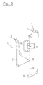
- FIG. 2 shows a schematic partial representation of another exemplary embodiment of the machine 10.
- the good side of Fiber web produced by a cover layer lying on the underside.
- the machine 10 is shown again as a gap former.
- it may also be embodied as a hybrid former or as a wire former.
- a provided in the wire section displacement drainage zone 12 is provided again.
- the flow direction S of the displacement gas is chosen so that this displacement gas flows through the membrane 24, first the lower wire 16, then the fibrous web and then the upper wire 14. This ensures again that the displacement gas flows from the good side in the direction of the back of the fibrous web.
- at least one blowing device, in particular a blow box, for dispensing the displacement gas and at least one suction device, in particular a suction box, for receiving the displacement gas can be arranged in the displacement dewatering zone 12.
- the displacement dewatering zone 12 is again arranged in the present case in a region in which the substances contained in the fibrous web such as in particular fillers, fines, contaminants, dyes and / or the like still have a high mobility.
- the total pressure applied to the fibrous web is composed of a structural pressure caused by the pressure drop across the membrane 24 and the hydraulic pressure.
- the fibrous web is guided again between the two sieve belts 14, 16 through the displacement dewatering zone 12.
- the two screen belts 14, 16 are again brought together in the region of a roller 18 to form an entry gap 20, which is charged with the pulp suspension supplied by the two-layer headbox 22.
- the fibrous web is guided at least substantially rectilinearly through the displacement dewatering zone 12 together with the two sieve belts 14, the fibrous web lying between the two sieve belts 14, 16 is in the present embodiment shown in FIG the membrane 24 is guided around a roller 26, which may in particular be a suction roller.
- the lower wire 16 is separated from the upper wire 14 together with the fibrous web 30 in the region of a separating element 28.
- FIG. 3 shows, in a diagrammatic partial representation, a further embodiment of the machine 10.
- the machine 10 is designed as a hybrid former with an attached longitudinal wire former.
- this machine comprises an upper screen 32 for producing a cover layer forming the good side of the fibrous web 30.
- This cover layer is applied by the upper screen 32 in the region of a roller 34 to a further layer formed on a lower screen 36.
- the two screens 32, 36 each have a headbox 38 and 40, respectively.
- a displacement dewatering zone 12 which again comprises a membrane 24 in the present case.
- at least one blowing device, in particular a blow box, for dispensing the displacement gas and at least one suction device, in particular a suction box, for receiving the displacement gas can be arranged in the displacement dewatering zone 12.
- the flow direction S of the displacement gas is chosen so that this first the membrane 24, then the fibrous web and then the lower sieve 36 flows through. It is thus ensured again in the present case that in the displacement dewatering zone 12, which is again here in the mobility of the particles contained in the fibrous web, the flow direction S of the displacement gas is selected so that the displacement gas from the Gutseite toward the back of the Fibrous web flows.
Abstract
Description
Die Erfindung betrifft ein Verfahren zur Herstellung einer insbesondere mehrschichtigen und/oder mehrlagigen Faserstoffbahn mit einer Gutseite und Rückseite, bei dem die Faserstoffbahn zumindest teilweise durch eine Verdrängungsentwässerung mittels Verdrängungsgas entwässert wird. Sie betrifft ferner eine Maschine zur Herstellung einer solchen Faserstoffbahn. Bei der Faserstoffbahn kann es sich insbesondere um eine Papier- oder Kartonbahn handeln.The invention relates to a method for producing a particularly multi-layered and / or multilayer fibrous web with a Gutseite and back, in which the fibrous web is at least partially dewatered by a displacement drainage by means of displacement gas. It further relates to a machine for producing such a fibrous web. The fibrous web may in particular be a paper or board web.
Verfahren und Maschinen der eingangs genannten Art, bei denen die Entwässerung zumindest teilweise durch eine Verdrängungsentwässerung erfolgt, sind beispielsweise aus den Druckschriften
Bei der so genannten Verdrängungsentwässerung (Displacement Dewatering Process) wird Wasser durch die Anwendung eines Gasdifferenzdrucks aus der Faserstoffbahn entfernt. Dabei wird das sich in den Poren zwischen den Fasern befindende Wasser aus dem Papiervlies herausgeblasen. Im Vergleich zum konventionellen Nasspressen beispielsweise in einem einfach oder doppelt befilzten Walzenspalt hat das einer Verdrängungsentwässerung unterzogene Papier ein höheres spezifisches Volumen. Mit der Verdrängungsentwässerung mittels Verdrängungsgas, wie beispielsweise Luft werden hohe Trockengehaltssteigerungen erreicht. Kennzeichnend ist die geringe Dichte des entwässerten Papiers bzw. Kartons. Zusätzlich kann durch eine Migration der Feinstoffe unter Umständen auch eine bessere Spaltfestigkeit der Faserstoffbahn erreicht werden kann. Dieser Effekt tritt jedoch nur ein, wenn die Entwässerungsrichtung in der mobilen Phase gleich bleibt.In so-called Displacement Dewatering Process, water is removed from the fibrous web by the application of a gas differential pressure. In this case, the water in the pores between the fibers is blown out of the paper web. For example, compared to conventional wet pressing in a single or double felted nip, the displacement dewatered paper has a higher specific volume. With the displacement drainage by means of displacement gas, such as air high dry content increases are achieved. Characteristic is the low density of the dewatered paper or cardboard. In addition, migration of the fines may also improve the fission resistance of the fibrous web can be achieved. However, this effect only occurs if the drainage direction remains the same in the mobile phase.
Insbesondere bei Papier- und Kartonsorten mit einer ausgeprägten Gutseite oder Decke ist eine hohe Reinheit und Weiße erwünscht. Bei den bisher bekannten Verfahren und Maschinen der eingangs genannten Art kann es bei der Herstellung mehrschichtiger und/oder mehrlagiger Produkte auf der Basis von Rohstoffen unterschiedlichen Weißgrades zu einer Verunreinigung der Decke durch Partikel aus den darüber bzw. darunter liegenden Bahnlagen oder -schichten kommen.Particularly in paper and board grades with a pronounced Gutseite or blanket high purity and whiteness is desired. In the hitherto known methods and machines of the type mentioned above, in the production of multilayered and / or multilayered products based on raw materials of different whiteness, contamination of the blanket by particles from the overlying or underlying web layers or layers can occur.
Der Erfindung liegt die Aufgabe zugrunde, ein verbessertes Verfahren sowie eine verbesserte Maschine der eingangs genannten Art zu schaffen, bei denen die zuvor genannten Probleme beseitigt sind.The invention has for its object to provide an improved method and an improved machine of the type mentioned, in which the aforementioned problems are eliminated.
Diese Aufgabe wird erfindungsgemäß gelöst durch ein Verfahren zur Herstellung einer insbesondere mehrschichtigen und/oder mehrlagigen Faserstoffbahn mit einer Gutseite und einer Rückseite, bei dem die Faserstoffbahn zumindest teilweise durch eine Verdrängungsentwässerung mittels Verdrängungsgas entwässert wird, wobei die Strömungsrichtung des Verdrängungsgases zumindest in einem Bereich, in dem in der Faserstoffbahn enthaltene Stoffe wie insbesondere Füllstoffe, Feinstoffe, Schmutzstoffe, Farbstoffe und/oder dergleichen noch eine vorgebbare Mobilität aufweisen, so gewählt wird, dass das Verdrängungsgas von der Gutseite in Richtung der Rückseite der Faserstoffbahn strömt.This object is achieved by a method for producing a particular multilayer and / or multilayer fibrous web having a Gutseite and a back, in which the fibrous web is at least partially dewatered by a Verdrängungsentwässerung means of displacement gas, wherein the flow direction of the displacement gas at least in a region in the materials contained in the fibrous web such as in particular fillers, fines, contaminants, dyes and / or the like still have a predeterminable mobility is chosen so that the displacement gas flows from the Gutseite in the direction of the back of the fibrous web.
Eine Verschmutzung der Gutseite bzw. Decke wird also durch gerichtetes Durchströmen der Bahn von der Gutseite zur Rückseite hin vermieden. Dabei erfolgt die Verdrängungsentwässerung bereits in sehr frühen Phase des Papier- bzw. Kartonherstellungsprozesses, in der die in der Faserstoffbahn enthaltenen kleinen und kleinsten Partikel, wie insbesondere Füllstoffe, Feinstoffe, Schmutzstoffe, Faserstoffe und/oder dergleichen noch eine hohe Mobilität aufweisen. Das zu entfernende Wasser verläuft in dieser Phase hoher Mobilität bevorzugt von der Decke in Richtung Rückseite der Faserstoffbahn. Füll- und Feinstoffe, usw. werden in der Decke festgehalten. Ein Auswaschen dieser Stoffe aus der Decke wird also vermieden.Soiling of the good side or ceiling is thus avoided by directed passage of the web from the good side to the back. Displacement drainage takes place at a very early stage of the paperboard or paperboard production process, in which the small and minute particles contained in the fibrous web, in particular fillers, fines, contaminants, fibrous materials and / or the like, still have a high degree of mobility. The water to be removed runs in this phase of high mobility preferably from the ceiling towards the back of the fibrous web. Fillers, fines, etc. are held in the ceiling. A washing out of these substances from the ceiling is thus avoided.
Die Mobilität der genannten Partikel nimmt mit abnehmender Bahnfeuchte, d.h. zunehmendem Trockengehalt der Faserstoffbahn ab.The mobility of said particles decreases with decreasing web moisture, i. increasing dry content of the fibrous web.
Gemäß einer bevorzugten praktischen Ausgestaltung des erfindungsgemäßen Verfahrens liegt der vorgebbare Mobilitätsbereich zwischen der Wasserlinie und der Grenze, bei der die durchschnittlichen Partikeldurchmesser der in der Faserstoffbahn enthaltenen Stoffe wie insbesondere Füllstoffe, Feinstoffe, Schmutzstoffe, Farbstoffe und/oder dergleichen größer als der durchschnittliche Kapillarendurchmesser der Faserstoffbahn wird.According to a preferred practical embodiment of the method according to the invention, the predeterminable mobility range lies between the waterline and the boundary at which the average particle diameter of the substances contained in the fibrous web such as in particular fillers, fines, contaminants, dyes and / or the like greater than the average capillary diameter of the fibrous web becomes.
Bevorzugt ist der vorgebbare Mobilitätsbereich dadurch bestimmt, dass die Faserstoffbahn in diesem Bereich einen über die verschiedenen Schichten bzw. Lagen betrachtet mittleren Trockengehalt besitzt, der zwischen einem unteren Wert von etwa 5 bis etwa 8 % und einem oberen Wert von etwa 40 bis etwa 50 % liegt.Preferably, the predeterminable mobility range is determined by the fact that the fibrous web in this area has an average dry content, which is considered between the various layers or layers, which is between a lower value of about 5 to about 8% and an upper value of about 40 to about 50%. lies.
Bei mehrlagigen Formerkonzepten bzw. bei der Herstellung einer mehrlagigen Faserstoffbahn ist der vorgebbare Mobilitätsbereich nach unten vorteilhafterweise durch einen über die verschiedenen Lagen betrachtet vorgebbaren mittleren Trockengehalt der Faserstoffbahn beim Vergautschen der Lagen begrenzt. Dabei beträgt der vorgebbare mittlere Trockengehalt der Faserstoffbahn beim Vergautschen der Lagen zweckmäßigerweise etwa 8 bis etwa 12 %.In the case of multilayer shaping concepts or in the production of a multilayer fibrous web, the predeterminable mobility range downwards is advantageously limited by a mean dry content of the fibrous web which is predeterminable over the various layers when the layers are covered. The predetermined mean dry content of the fibrous web when Vergautschen the layers is expediently about 8 to about 12%.
Bei einlagigen ein- oder mehrschichtigen Formerkonzepten bzw. der Herstellung einer einlagigen ein- oder mehrschichtigen Faserstoffbahn ist der vorgebbare Mobilitätsbereich nach unten bevorzugt durch die Wasserlinie begrenzt. Dabei liegt die untere Grenze des vorgebbaren Mobilitätsbereichs zweckmäßigerweise bei einem Trockengehalt von etwa 5 bis etwa 8 %. Dabei handelt es sich insbesondere wieder um den über die verschiedenen Lagen bzw. Schichten betrachtet mittleren Trockengehalt.In the case of single-layer single-layer or multi-layered form concepts or the production of a single-layer single-layer or multi-layer fibrous web, the predeterminable range of mobility downwards is preferably limited by the waterline. The lower limit of the predefinable mobility range is expediently at a dry content of about 5 to about 8%. It is about especially again around the mean dry content over the different layers or layers.
Gemäß einer bevorzugten praktischen Ausgestaltung des erfindungsgemäßen Verfahrens wird in einer jeweiligen Verdrängungsentwässerungszone die Faserstoffbahn über ein einen Strömungswiderstand aufweisendes permeables Band mit dem Verdrängungsgas beaufschlagt, so dass auf die Faserstoffbahn ein Gesamtdruck aufgebracht wird, der sich aus einem durch den Druckabfall an dem permeablen Band bedingten Strukturdruck und dem hydraulischen Druck zusammensetzt.According to a preferred practical embodiment of the method according to the invention, the fibrous web is acted upon by a permeable strip having a flow resistance in a respective displacement dewatering zone, so that a total pressure is applied to the fibrous web, resulting from a structure pressure caused by the pressure drop across the permeable band and the hydraulic pressure.
In einer jeweiligen Verdrängungsentwässerungszone wird somit eine Verdrängungsentwässerungspresse gebildet, was bedeutet, dass der während der Verdrängungsentwässerung auf die Faserstoffbahn wirkende Druck auf der Seite, auf der das gasförmige Fluid zugeführt wird, zumindest teilweise auch als Strukturdruck wirkt. Dieser auf der Zufuhrseite wirkende Strukturdruck ergibt sich aus dem Druckabfall an dem auf der betreffenden Seite liegenden, einen Strömungswiderstand aufweisenden permeablen Band. Entsprechend setzt sich der aufgebrachte Gesamtdruck aus dem hydraulischen und diesem Strukturdruck zusammen. Unter Strukturdruck kann also der von Feststoffen übertragene Druck verstanden werden, wobei sich diese Druckkomponente dadurch auszeichnet, dass sie gerichtet wirkt. Dagegen wirkt der hydraulische Druck in alle Richtungen.A displacement dewatering press is thus formed in a respective displacement dewatering zone, which means that the pressure acting on the fibrous web during the displacement dewatering on the side on which the gaseous fluid is supplied at least partially also acts as a structure pressure. This structural pressure acting on the supply side results from the pressure drop across the permeable band on the side in question having a flow resistance. Accordingly, the total applied pressure is composed of the hydraulic and structural pressure. Structural pressure can thus be understood to mean the pressure transferred by solids, whereby this pressure component is characterized in that it acts in a directed manner. In contrast, the hydraulic pressure acts in all directions.
Vorteilhafterweise wird als mit einem Strömungswiderstand versehenes permeables Band eine Membran verwendet. Grundsätzlich ist jedoch beispielsweise auch die Verwendung eines Siebes oder dergleichen denkbar.Advantageously, a membrane is used as the permeable band provided with a flow resistance. Basically, however, for example, the use of a sieve or the like is conceivable.
Eine jeweilige Verdrängungsentwässerungszone kann also beispielsweise durch die Verwendung eines einen entsprechenden Strömungswiderstand aufweisenden permeablen Bandes wie insbesondere einer Membran, eines Siebs oder dergleichen als Verdrängungsentwässerungs-Presseinheit wirken, bei der die Bahn auch durch einen Strukturdruck beaufschlagt wird.A respective displacement drainage zone can therefore act, for example, by the use of a permeable belt having a corresponding flow resistance, such as, in particular, a membrane, a sieve or the like, as a displacement dewatering press unit, in which the web is also subjected to a structural pressure.
Das beispielsweise durch eine Membran, ein Sieb oder dergleichen gebildete, einen Strömungswiderstand aufweisende permeable Band bewirkt überdies eine Vergleichmäßigung der Durchströmung der Bahn.The permeable band, which has a flow resistance and is formed, for example, by a membrane, a sieve or the like, moreover homogenises the flow through the web.
Erfolgt eine Verdrängungsentwässerung in mehreren in Bahnlaufrichtung aufeinander folgenden Verdrängungsentwässerungszonen oder -teilzonen, so wird gemäß einer bevorzugten praktischen Ausgestaltung des erfindungsgemäßen Verfahrens der auf die Faserstoffbahn aufgebrachte Gesamtdruck in Bahnlaufrichtung schrittweise erhöht. Dabei können beispielsweise zwei oder auch mehrere Verdrängungsentwässerungszonen bzw. -presseinheiten durchfahren werden.If displacement displacement takes place in a plurality of displacement dewatering zones or partial zones following one another in the direction of web travel, the total pressure applied to the fibrous web in the web running direction is gradually increased in accordance with a preferred practical embodiment of the method according to the invention. In this case, for example, two or more displacement dewatering zones or press units can be passed through.
Alternativ oder zusätzlich kann auch der auf der Faserstoffbahn aufgebrachte hydraulische Druck schrittweise erhöht werden. Die Bezugsfläche ist hierbei die deckseitige Oberfläche der Faserstoffbahn. Mit dieser Maßnahme kann beispielsweise die Strömungsgeschwindigkeit begrenzt werden. Auch in diesem Fall können beispielsweise wieder zwei oder auch mehrere Verdrängungsentwässerungs-Presseinheiten durchfahren werden.Alternatively or additionally, the hydraulic pressure applied to the fibrous web can also be increased stepwise. The reference surface here is the top surface of the fibrous web. With this measure, for example, the flow velocity can be limited. Also in this case, for example, again two or more displacement dewatering press units can be passed through.
Gemäß einer weiteren vorteilhaften Ausgestaltung des erfindungsgemäßen Verfahrens kann alternativ oder zusätzlich auch der aufgebrachte hydraulische Differenzdruck zwischen der Gut- bzw. Deckseite und der Rückseite der Faserstoffbahn schrittweise erhöht werden, wodurch beispielsweise wieder die Strömungsgeschwindigkeit begrenzt werden kann.According to a further advantageous embodiment of the method according to the invention, alternatively or additionally, the applied hydraulic differential pressure between the crop or cover side and the back of the fibrous web can be gradually increased, whereby, for example, again the flow velocity can be limited.
Dabei kann der hydraulische Differenzdruck vorteilhafterweise zumindest dadurch schrittweise erhöht werden, dass in den verschiedenen Verdrängungsentwässerungszonen bzw. -presseinheiten auf der Gutseite der Faserstoffbahn permeable Bänder unterschiedlicher Permeabilität verwendet werden. Der aufgebrachte hydraulische Differenzdruck zwischen der Gutseite und der Rückseite kann also beispielsweise durch eine gezielte Wahl der Permeabilität des permeablen Bandes, d.h. beispielsweise einer Membran, eines Siebs oder dergleichen auf der Deckenseite entsprechend beeinflusst werden.In this case, the hydraulic differential pressure can advantageously be increased stepwise, at least in that permeable bands of different permeability are used in the various displacement dewatering zones or pressing units on the good side of the fibrous web. The applied hydraulic differential pressure between the Gutseite and the back so for example by a targeted choice of permeability the permeable band, ie for example a membrane, a sieve or the like on the ceiling side are influenced accordingly.
Alternativ oder zusätzlich kann der hydraulische Differenzdruck vorteilhafterweise zumindest dadurch schrittweise erhöht werden, dass in den verschiedenen Verdrängungsentwässerungszonen bzw. -presseinheiten auf der Rückseite der Faserstoffbahn für unterschiedliche zusätzliche Strömungswiderstände gesorgt wird.Alternatively or additionally, the hydraulic differential pressure can advantageously be increased stepwise at least by providing different additional flow resistances in the various displacement dewatering zones or pressing units on the rear side of the fibrous web.
Gemäß einer bevorzugten praktischen Ausgestaltung des erfindungsgemäßen Verfahrens wird in wenigstens einer Verdrängungsentwässerungszone auf der Rückseite der Faserstoffbahn zumindest eine Membran, vorzugsweise zumindest eine Antirückbefeuchtungs-Membran (anti-rewet fabric) verwendet.According to a preferred practical embodiment of the method according to the invention at least one membrane, preferably at least one anti-rewet membrane is used in at least one displacement dewatering zone on the back of the fibrous web.
Vorteilhafterweise kann der hydraulische Differenzdruck also auch zumindest dadurch schrittweise erhöht werden, dass in den verschiedenen Verdrängungsentwässerungszonen bzw. -presseinheiten auf der Rückseite der Faserstoffbahn eine unterschiedliche Zahl von Membranen verwendet wird. Der zur Beeinflussung des hydraulischen Differenzdrucks vorgesehene zusätzliche Strömungswiderstand auf der Rückseite kann also beispielsweise durch eine weitere Membran oder eine gezielt eingestellte, insbesondere niedrige Permeabilität einer Antirückbefeuchtungs-Membran erzeugt werden.Advantageously, the hydraulic differential pressure can therefore also be increased stepwise, at least by using a different number of membranes in the different displacement dewatering zones or pressing units on the rear side of the fibrous web. The provided for influencing the hydraulic differential pressure additional flow resistance on the back can therefore be generated for example by a further membrane or a specifically set, in particular low permeability of an anti-rewet membrane.
Auf der Rückseite der Faserstoffbahn kann in Durchströmungsrichtung betrachtet nach der eine Rückbefeuchtung verhindernden Antirückbefeuchtungs-Membran beispielsweise auch ein weiteres Bespannungsband vorgesehen sein. Dabei kann es sich bei diesem Bespannungsband im Fall einer im Former vorgesehenen Verdrängungsentwässerungszone beispielsweise um ein Entwässerungssieb handeln. Alternativ oder zusätzlich kann bei einer Anordnung einer jeweiligen Verdrängungsentwässerungszone im Pressenbereich beispielsweise auch ein Entwässerungsfilz vorgesehen sein.On the back side of the fibrous web, viewed in the direction of flow, after the anti-rewet membrane preventing re-wetting, for example, another covering band may be provided. In the case of a displacement dewatering zone provided in the former, this tensioning band can be, for example, a dewatering screen. Alternatively or additionally, in the case of an arrangement of a respective displacement dewatering zone in the press area, for example, a dewatering felt may also be provided.
Der auf die Faserstoffbahn aufgebrachte Gesamtdruck wird vorzugsweise höher gewählt als der Umgebungsdruck. Bei diesem Gesamtdruck handelt es sich, wie bereits erwähnt, um die Summe aus dem hydraulischen Druck und dem Strukturdruck.The total pressure applied to the fibrous web is preferably selected to be higher than the ambient pressure. As already mentioned, this total pressure is the sum of the hydraulic pressure and the structure pressure.
Von Vorteil ist insbesondere auch, wenn die in Bahnlaufrichtung betrachtet erste Verdrängungsentwässerungszone in der Siebpartie der betreffenden Papiermaschine vorgesehen ist.It is also particularly advantageous if the first displacement dewatering zone, viewed in the web running direction, is provided in the wire section of the relevant paper machine.
Diese erste Verdrängungsentwässerungszone kann beispielsweise aber auch am Anfang der Pressenpartie der betreffenden Papiermaschine vorgesehen sein. Grundsätzlich kann diese Pressenpartie auch wenigstens eine Schuhpresse umfassen.However, this first displacement dewatering zone may, for example, also be provided at the beginning of the press section of the relevant paper machine. In principle, this press section can also comprise at least one shoe press.
Gemäß einer zweckmäßigen alternativen Ausgestaltung des erfindungsgemäßen Verfahrens ist diese erste Verdrängungsentwässerungszone innerhalb der Pressenpartie vorgesehen. Dabei kann diese Pressenpartie grundsätzlich auch wieder wenigstens eine Schuhpresse enthalten.According to an expedient alternative embodiment of the method according to the invention, this first displacement dewatering zone is provided within the press section. In principle, this press section may again contain at least one shoe press.
Von Vorteil ist insbesondere auch, wenn die in Bahnlaufrichtung betrachtet letzte Verdrängungsentwässerungszone nach der Pressenpartie der betreffenden Papiermaschine, bei der es sich um eine konventionelle Pressenpartie handeln kann, vorgesehen ist. Dabei kann auch diese Pressenpartie grundsätzlich wieder wenigstens eine Schuhpresse umfassen.It is also of particular advantage if the last displacement dewatering zone considered in the web running direction is provided after the press section of the relevant paper machine, which may be a conventional press section. In principle, this press section may again comprise at least one shoe press.
Bevorzugt ist die letzte Verdrängungsentwässerungszone unmittelbar vor der Trockenpartie der betreffenden Papiermaschine vorgesehen.Preferably, the last displacement dewatering zone is provided immediately before the dryer section of the respective paper machine.
Gemäß einer weiteren vorteilhaften Ausgestaltung des erfindungsgemäßen Verfahrens wird für zumindest eine Verdrängungsentwässerungszone bzw. - presseinheit die Temperatur des Verdrängungsgases > 40°C gewählt. Dabei ist diese Temperatur des Verdrängungsgases vorzugsweise < 250°C. Weiterhin kann vorgesehen sein, dass die Temperatur des Verdrängungsgases in in Laufrichtung der Faserstoffbahn benachbarten Verdrängungsentwässerungsteilzonen kontinuierlich und/oder bereichsweise zu- und/oder abnimmt. Bevorzugt wird die Temperatur des Verdrängungsgases unterhalb der dem Zufuhrdruck entsprechenden Siedetemperatur von Wasser gewählt. Auch kann die Temperatur der Faserstoffbahn beim Verlassen der Verdrängungsentwässerungszone bzw. - teilzone maximal der dem Umgebungsdruck entsprechenden Siedetemperatur von Wasser gewählt werden.According to a further advantageous embodiment of the method according to the invention, the temperature of the displacement gas is chosen to be> 40 ° C. for at least one displacement dewatering zone or pressing unit. In this case, this temperature of the displacement gas is preferably <250 ° C. Furthermore, can be provided that the temperature of the displacement gas in the direction of the fibrous web adjacent Verdrängungsentwässerungsteilzonen continuously and / or partially increasing and / or decreasing. The temperature of the displacement gas is preferably chosen below the boiling temperature of water corresponding to the feed pressure. The temperature of the fibrous web when leaving the displacement dewatering zone or partial zone can be selected to be at most the boiling point of water corresponding to the ambient pressure.
Die Gutseite der Faserstoffbahn kann beispielsweise durch eine auf der Oberseite liegende Deckschicht erzeugt werden. Grundsätzlich ist es jedoch auch möglich, die Gutseite der Faserstoffbahn durch eine auf der Unterseite liegende Deckschicht zu erzeugen.The good side of the fibrous web can be produced, for example, by a cover layer lying on top. In principle, however, it is also possible to produce the good side of the fibrous web by a cover layer lying on the underside.
Gemäß einer weiteren vorteilhaften Ausgestaltung wird eine die Gutseite der Faserstoffbahn bildende Decklage auf einem oberen Sieb der betreffenden Papiermaschine erzeugt.According to a further advantageous embodiment, a cover layer forming the good side of the fibrous web is produced on an upper wire of the relevant paper machine.
Sind mehrere Verdrängungsentwässerungszonen vorgesehen, so ist gemäß einer vorteilhaften Ausgestaltung des erfindungsgemäßen Verfahrens die Strömungsrichtung des Verdrängungsgases in allen Verdrängungsentwässerungszonen so gewählt, dass das Verdrängungsgas von der Gutseite in Richtung der Rückseite der Faserstoffbahn strömt. Grundsätzlich ist es jedoch auch denkbar, die Strömungsrichtung des Verdrängungsgases in den verschiedenen Verdrängungsentwässerungszonen unterschiedlich zu wählen, wobei jedoch in einer jeweiligen Verdrängungsentwässerungszone im Mobilitätsbereich der in der Faserstoffbahn enthaltenden Stoffe wie insbesondere Füllstoffe, Feinstoffe, Schmutzstoffe, Farbstoffe und/oder dergleichen die Strömungsrichtung bevorzugt von der Gutseite zur Rückseite hin gewählt wird.If a plurality of displacement drainage zones are provided, the flow direction of the displacement gas in all displacement drainage zones is selected such that the displacement gas flows from the good side toward the rear side of the fibrous web. In principle, however, it is also conceivable to choose the flow direction of the displacement gas in the different displacement drainage zones, but in a respective displacement dewatering zone in the mobility range of substances contained in the fibrous web such as in particular fillers, fines, contaminants, dyes and / or the like, the flow direction of the good side is selected to the back.
Bei dem Verdrängungsgas kann es sich beispielsweise um Luft, überhitzten Dampf usw. handeln.The displacement gas may be, for example, air, superheated steam, etc.
Grundsätzlich kann zwischen dem einen Strömungswiderstand aufweisenden permeablen Band bzw. Membran oder Sieb und der Faserstoffbahn auch noch eine weitere poröse Bespannung, insbesondere Sieb, vorgesehen sein. So kann die Faserstoffbahn beispielsweise auch zwischen zwei Siebbändern durch eine jeweilige, vorzugsweise mit einer Membran oder dergleichen versehene Verdrängungsentwässerungszone geführt sein.In principle, a further porous covering, in particular a sieve, can also be provided between the permeable band or membrane or sieve having a flow resistance and the fibrous web. For example, the fibrous web can also be passed between two sieve belts through a respective displacement drainage zone, preferably provided with a membrane or the like.
Die erfindungsgemäße Maschine zur Herstellung einer insbesondere mehrschichtigen und/oder mehrlagigen Faserstoffbahn mit einer Gutseite und einer Rückseite umfasst wenigstens eine Verdrängungsentwässerungszone, in der die Faserstoffbahn durch eine Verdrängungsentwässerung mittels Verdrängungsgas entwässert wird, wobei die Strömungsrichtung des Verdrängungsgases zumindest in einem Bereich, in dem in der Faserstoffbahn enthaltene Stoffe wie insbesondere Füllstoffe, Feinstoffe, Schmutzstoffe, Farbstoffe und/oder dergleichen noch eine vorgebbare Mobilität aufweisen, so gewählt ist, dass das Verdrängungsgas von der Gutseite in Richtung der Rückseite der Faserstoffbahn strömt. In der Verdrängungsentwässerungszone kann beispielsweise wenigstens eine Blaseinrichtung, insbesondere ein Blaskasten, zur Abgabe des Verdrängungsgases und wenigstens eine Saugeinrichtung, insbesondere ein Saugkasten, zur Aufnahme des Verdrängungsgases angeordnet sein.The inventive machine for producing a particular multilayer and / or multilayer fibrous web having a Gutseite and a back comprises at least one Verdrängungsentwässerungszone in which the fibrous web is dewatered by a displacement drainage by means of displacement gas, wherein the flow direction of the displacement gas at least in a region in which in the Fiber material web containing substances such as in particular fillers, fines, contaminants, dyes and / or the like still have a predeterminable mobility is chosen so that the displacement gas flows from the Gutseite towards the back of the fibrous web. In the displacement dewatering zone, for example, at least one blowing device, in particular a blow box, for dispensing the displacement gas and at least one suction device, in particular a suction box, can be arranged to receive the displacement gas.
Gemäß einer bevorzugten praktischen Ausführungsform der erfindungsgemäßen Maschine umfasst zumindest eine Verdrängungsentwässerungszone eine Verdrängungsentwässerungs-Clusterpresse, bei der durch eine Mehrwalzenanordnung eine Druckkammer gebildet wird, durch die die Faserstoffbahn hindurchgeführt wird.According to a preferred practical embodiment of the machine according to the invention, at least one displacement dewatering zone comprises a displacement dewatering cluster press in which a pressure chamber is formed by a multi-roll arrangement, through which the fibrous web is passed.
Weitere bevorzugte Ausführungsformen der erfindungsgemäßen Maschine sind in den Unteransprüchen angegeben.Further preferred embodiments of the machine according to the invention are specified in the subclaims.
Die Erfindung wird im Folgenden anhand von Ausführungsbeispielen unter Bezugnahme auf die Zeichnung näher erläutert.The invention will be explained in more detail below with reference to exemplary embodiments with reference to the drawing.
In dieser zeigen:
- Figur 1
- eine schematische Teildarstellung einer beispielhaften Ausführungsform einer erfindungsgemäßen Maschine zur Herstellung einer Faserstoffbahn, bei der die Gutseite der Faserstoffbahn durch eine auf der Oberseite liegende Deckschicht erzeugt wird;
- Figur 2
- eine schematische Teildarstellung einer weiteren Ausführungsform der Maschine, bei der die Gutseite der Faserstoffbahn durch eine auf der Unterseite liegende Deckschicht erzeugt wird; und
- Figur 3
- eine schematische Teildarstellung einer weiteren Ausführungsform der Maschine, die zur Erzeugung einer die Gutseite der Faserstoffbahn bildenden Decklage ein oberes Sieb umfasst.
- FIG. 1
- a schematic partial view of an exemplary embodiment of a machine according to the invention for producing a fibrous web, in which the good side of the fibrous web is produced by a cover layer lying on the top;
- FIG. 2
- a schematic partial view of another embodiment of the machine, in which the good side of the fibrous web is produced by a cover layer lying on the underside; and
- FIG. 3
- a schematic partial view of a further embodiment of the machine, which comprises an upper screen to produce a good side of the fibrous web forming cover layer.
Figur 1 zeigt in schematischer Teildarstellung eine beispielhafte Ausführungsform einer erfindungsgemäßen Maschine 10 zur Herstellung einer zweischichtigen Faserstoffbahn mit einer Gutseite und einer Rückseite. Bei der Faserstoffbahn kann es sich insbesondere um eine Papier- oder Kartonbahn handeln. Die Maschine 10 ist darstellungsgemäß als ein Spaltformer ausgeführt. Selbstverständlich kann sie auch als ein Hybridformer oder als ein Langsiebformer ausgeführt sein.FIG. 1 shows, in a schematic partial representation, an exemplary embodiment of a
Im vorliegenden Fall wird die Gutseite der Faserstoffbahn durch eine auf der Oberseite liegende Deckschicht erzeugt.In the present case, the good side of the fibrous web is produced by a top layer lying on the top.
Die Maschine 10 umfasst eine Verdrängungsentwässerungszone 12, in der die Faserstoffbahn durch eine Verdrängungsentwässerung mittels Verdrängungsgas entwässert wird. Dabei ist die Strömungsrichtung S des Verdrängungsgases so gewählt, dass das Verdrängungsgas von der Gutseite in Richtung der Rückseite der Faserstoffbahn strömt. In der Verdrängungsentwässerungszone 12 kann beispielsweise wenigstens eine Blaseinrichtung, insbesondere ein Blaskasten, zur Abgabe des Verdrängungsgases und wenigstens eine Saugeinrichtung, insbesondere ein Saugkasten, zur Aufnahme des Verdrängungsgases angeordnet sein.The
Die Verdrängungsentwässerungszone 12 ist in einem Bereich vorgesehen, in dem in der Faserstoffbahn enthaltene Stoffe, wie insbesondere Füllstoffe, Feinstoffe, Schmutzstoffe, Farbstoffe und/oder dergleichen noch eine hohe Mobilität aufweisen.The
Im vorliegenden Fall ist die Verdrängungsentwässerungszone 12 in der Siebzone vorgesehen. Dabei wird die Faserstoffbahn zwischen zwei Siebbändern 14, 16 liegend durch die Verdrängungsentwässerungszone 12 hindurchgeführt. Die beiden Siebbänder 14, 16 werden zuvor im Bereich einer Walze 18 unter Bildung eines Eintrittsspalts 20 zusammengeführt, in den mittels eines Zweischicht-Stoffauflaufs 22 die zur Herstellung der Faserstoffbahn benötigte Faserstoffsuspension eingeführt wird.In the present case, the
Die Faserstoffbahn wird über ein einen Strömungswiderstand aufweisendes permeables Band, das hier beispielsweise durch eine Membran 24 gebildet ist, mit dem Verdrängungsgas beaufschlagt. Zwischen der Membran 24 und der Faserstoffbahn liegt hier allerdings noch das obere Siebband 14.The fibrous web is acted upon by a flow resistance permeable tape, which is formed here for example by a
Aufgrund der Membran 24 wird auf die Faserstoffbahn also ein Gesamtdruck aufgebracht, der sich aus einem durch den Druckabfall an der Membran 24 bedingten Strukturdruck und dem hydraulischen Druck zusammensetzt.Due to the
Figur 2 zeigt in schematischer Teildarstellung eine weitere beispielhafte Ausführungsform der Maschine 10. Im vorliegenden Fall wird die Gutseite der Faserstoffbahn durch eine auf der Unterseite liegende Deckschicht erzeugt. Die Maschine 10 ist darstellungsgemäß widerum als ein Spaltformer ausgeführt. Selbstverständlich kann sie auch als ein Hybridformer oder als ein Langsiebformer ausgeführt sein.Figure 2 shows a schematic partial representation of another exemplary embodiment of the
Auch im vorliegenden Fall ist wieder ein in der Siebpartie vorgesehene Verdrängungsentwässerungszone 12 vorgesehen. In diesem Fall ist die Strömungsrichtung S des Verdrängungsgases jedoch so gewählt, dass dieses Verdrängungsgas nach der Membran 24 zunächst das untere Siebband 16, dann die Faserstoffbahn und anschließend das obere Siebband 14 durchströmt. Damit ist wieder sichergestellt, dass das Verdrängungsgas von der Gutseite in Richtung der Rückseite der Faserstoffbahn strömt. In der Verdrängungsentwässerungszone 12 kann beispielsweise wenigstens eine Blaseinrichtung, insbesondere ein Blaskasten, zur Abgabe des Verdrängungsgases und wenigstens eine Saugeinrichtung, insbesondere ein Saugkasten, zur Aufnahme des Verdrängungsgases angeordnet sein.Also in the present case, a provided in the wire section
Die Verdrängungsentwässerungszone 12 ist auch im vorliegenden Fall wieder in einem Bereich angeordnet, in dem die in der Faserstoffbahn enthaltenen Stoffe wie insbesondere Füllstoffe, Feinstoffe, Schmutzstoffe, Farbstoffe und/oder dergleichen noch eine hohe Mobilität aufweisen.The
Durch die Membran 24 wird wieder erreicht, dass sich der auf die Faserstoffbahn aufgebrachte Gesamtdruck aus einem durch den Druckabfall an der Membran 24 bedingten Strukturdruck und dem hydraulischen Druck zusammensetzt.Through the
Auch im vorliegenden Fall wird die Faserstoffbahn wieder zwischen den beiden Siebbändern 14, 16 durch die Verdrängungsentwässerungszone 12 geführt. Die beiden Siebbänder 14, 16 werden wieder im Bereich einer Walze 18 unter Bildung eines Eintrittsspalts 20 zusammengeführt, der mit der vom Zweischicht-Stoffauflauf 22 gelieferten Faserstoffsuspension beschickt wird.Also in the present case, the fibrous web is guided again between the two
Während bei der Ausführung gemäß Figur 1 die Faserstoffbahn zusammen mit den beiden Siebbändern 14, 16 zumindest im Wesentlichen geradlinig durch die Verdrängungsentwässerungszone 12 geführt wird, wird beim vorliegenden, in der Figur 2 wiedergegebenen Ausführungsbeispiel die zwischen den beiden Siebbändern 14, 16 liegende Faserstoffbahn zusammen mit der Membran 24 um eine Walze 26 geführt, bei der es sich insbesondere um eine Saugwalze handeln kann.While in the embodiment according to FIG. 1 the fibrous web is guided at least substantially rectilinearly through the
Im Anschluss an die Verdrängungsentwässerungszone 12 wird das untere Siebband 16 zusammen mit der Faserstoffbahn 30 im Bereich eines Trennelements 28 von dem oberen Siebband 14 getrennt.Subsequent to the
Figur 3 zeigt in schematischer Teildarstellung eine weitere Ausführungsform der Maschine 10. Die Maschine 10 ist darstellungsgemäß als ein Hybridformer mit einem aufgesetzten Langsiebformer ausgeführt.FIG. 3 shows, in a diagrammatic partial representation, a further embodiment of the
Im vorliegenden Fall umfasst diese Maschine zur Erzeugung einer die Gutseite der Faserstoffbahn 30 bildenden Decklage ein oberes Sieb 32. Diese Decklage wird durch das obere Sieb 32 im Bereich einer Walze 34 auf eine auf einem unteren Sieb 36 gebildete weitere Lage aufgebracht. Den beiden Sieben 32, 36 ist jeweils ein Stoffauflauf 38 bzw. 40 zugeordnet.In the present case, this machine comprises an
Im Anschluss an die der Walze 34 benachbarten Stelle, an der die beiden Lagen zusammengeführt werden, ist eine Verdrängungsentwässerungszone 12 vorgesehen, die auch im vorliegenden Fall wieder eine Membran 24 umfasst. In der Verdrängungsentwässerungszone 12 kann beispielsweise wenigstens eine Blaseinrichtung, insbesondere ein Blaskasten, zur Abgabe des Verdrängungsgases und wenigstens eine Saugeinrichtung, insbesondere ein Saugkasten, zur Aufnahme des Verdrängungsgases angeordnet sein.Subsequent to the location adjacent to the
Im vorliegenden Fall ist die Strömungsrichtung S des Verdrängungsgases so gewählt, dass dieses zunächst die Membran 24, dann die Faserstoffbahn und anschließend das untere Sieb 36 durchströmt. Es ist also auch im vorliegenden Fall wieder sichergestellt, dass in der Verdrängungsentwässerungszone 12, die auch hier wieder im Mobilitätsbereich der in der Faserstoffbahn enthaltenen Partikel liegt, die Strömungsrichtung S des Verdrängungsgases so gewählt ist, dass das Verdrängungsgas von der Gutseite in Richtung der Rückseite der Faserstoffbahn strömt.In the present case, the flow direction S of the displacement gas is chosen so that this first the
- 1010
- Maschinemachine
- 1212
- VerdrängungsentwässerungszoneDisplacement dewatering zone
- 1414
- Siebbandscreen belt
- 1616
- Siebbandscreen belt
- 1818
- Walzeroller
- 2020
- Eintrittsspaltentrance slit
- 2222
- Zweischicht-StoffauflaufTwo-layer headbox
- 2424
- Permeables Band mit Strömungswiderstand, MembranPermeable tape with flow resistance, membrane
- 2626
- Walzeroller
- 2828
- Trennelementseparating element
- 3030
- FaserstoffbahnFibrous web
- 3232
- Oberes SiebUpper sieve
- 3434
- Walzeroller
- 3636
- Unteres SiebLower sieve
- 3838
- Stoffauflaufheadbox
- 4040
- Stoffauflaufheadbox
- SS
- Strömungsrichtung des VerdrängungsgasesFlow direction of the displacement gas
Claims (66)
dadurch gekennzeichnet,
dass der vorgebbare Mobilitätsbereich zwischen der Wasserlinie und der Grenze liegt, bei der die durchschnittlichen Partikeldurchmesser der in der Faserstoffbahn (30) enthaltenen Stoffe wie insbesondere Füllstoffe, Feinstoffe, Schmutzstoffe, Farbstoffe und/oder dergleichen größer als der durchschnittliche Kapillarendurchmesser der Faserstoffbahn (30) wird.Method according to claim 1,
characterized,
in that the predeterminable range of mobility lies between the waterline and the boundary at which the average particle diameter of the substances contained in the fibrous web (30), in particular fillers, fines, contaminants, dyes and / or the like, becomes greater than the average capillary diameter of the fibrous web (30) ,
dadurch gekennzeichnet,
dass der vorgebbare Mobilitätsbereich dadurch bestimmt ist, dass die Faserstoffbahn (30) in diesem Bereich einen über die verschiedenen Schichten bzw. Lagen betrachtet mittleren Trockengehalt besitzt, der zwischen einem unteren Wert von etwa 5 bis etwa 8 % und einem oberen Wert von etwa 40 bis etwa 50 % liegt.Method according to claim 1 or 2,
characterized,
in that the predeterminable mobility range is determined by the fact that the fibrous web (30) in this region has an average dry content which is considered over the various layers or layers between a low of about 5 to about 8% and a high of about 40 to about 50%.
dadurch gekennzeichnet,
dass bei der Herstellung einer mehrlagigen Faserstoffbahn (30) der vorgebbare Mobilitätsbereich nach unten durch einen über die verschiedenen Lagen betrachtet vorgebbaren mittleren Trockengehalt der Faserstoffbahn (30) beim Vergautschen der Lagen begrenzt ist.Method according to one of the preceding claims,
characterized,
that in the production of a multilayer fibrous web (30) the predeterminable range of mobility downwards is limited by a predeterminable over the various layers average dry content of the fibrous web (30) when Vergautschen the layers.
dadurch gekennzeichnet,
dass der vorgebbare mittlere Trockengehalt der Faserstoffbahn (30) beim Vergautschen der Lagen etwa 8 bis etwa 12 % beträgt.Method according to claim 4,
characterized,
that the predeterminable mean dry content of the fibrous web (30) when gumming the layers is about 8 to about 12%.
dadurch gekennzeichnet,
dass bei der Herstellung einer einlagigen ein- oder mehrschichtigen Faserstoffbahn (30) der vorgebbare Mobilitätsbereich nach unten durch die Wasserlinie begrenzt ist.Method according to one of the preceding claims,
characterized,
that in the production of a single-layer single-layer or multi-layer fibrous web (30) the predeterminable range of mobility is limited downwards by the waterline.
dadurch gekennzeichnet,
dass die untere Grenze des vorgebbaren Mobilitätsbereichs bei einem insbesondere mittleren Trockengehalt von etwa 5 bis etwa 8 % liegt.Method according to claim 6,
characterized,
that the lower limit of the predeterminable mobility range at a particular average dry solids content of about 5 to about 8%.
dadurch gekennzeichnet,
dass in einer jeweiligen Verdrängungsentwässerungszone (12) die Faserstoffbahn (30) über ein einen Strömungswiderstand aufweisendes permeables Band (24) mit dem Verdrängungsgas beaufschlagt wird, so dass auf die Faserstoffbahn (30) ein Gesamtdruck aufgebracht wird, der sich aus einem durch den Druckabfall an dem permeablen Band (24) bedingten Strukturdruck und dem hydraulischen Druck zusammensetzt.Method according to one of the preceding claims,
characterized,
that in a respective displacement dewatering zone (12) the fibrous web (30) is acted upon by a flow-resistant permeable belt (24) with the displacement gas, so that on the fibrous web (30) a total pressure is applied, consisting of a structure pressure due to the pressure drop across the permeable belt (24) and the hydraulic pressure.
dadurch gekennzeichnet,
dass als mit einem Strömungswiderstand versehenes permeables Band (24) eine Membran verwendet wird.Method according to claim 8,
characterized,
in that a membrane is used as the permeable band (24) provided with a flow resistance.
dadurch gekennzeichnet,
dass als mit einem Strömungswiderstand versehenes permeables Band (24) ein Sieb verwendet wird.Method according to claim 8,
characterized,
that as a flow resistance provided permeable belt (24), a sieve is used.
dadurch gekennzeichnet,
dass die Verdrängungsentwässerung in mehreren in Bahnlaufrichtung aufeinander folgenden Verdrängungsentwässerungszonen (12) oder - teilzonen erfolgt und dabei der auf die Faserstoffbahn (30) aufgebrachte Gesamtdruck in Bahnlaufrichtung schrittweise erhöht wird.Method according to one of the preceding claims,
characterized,
that the displacement dewatering in a plurality in the web running direction of displacement successive dewatering zones (12) or - in some zones is carried out while the on the fibrous web (30) applied total pressure is gradually increased in the web running direction.
dadurch gekennzeichnet,
dass die Verdrängungsentwässerung in mehreren in Bahnlaufrichtung aufeinander folgenden Verdrängungsentwässerungszonen (12) oder - teilzonen erfolgt und dabei der auf die Faserstoffbahn (30) aufgebrachte hydraulische Druck in Bahnlaufrichtung schrittweise erhöht wird.Method according to one of the preceding claims,
characterized,
that the displacement dewatering in a plurality in the web running direction of displacement successive dewatering zones (12) or - in some zones is carried out while the on the fibrous web (30) hydraulic pressure applied to the web running direction is gradually increased.
dadurch gekennzeichnet,
dass die Verdrängungsentwässerung in mehreren in Bahnlaufrichtung aufeinander folgenden Verdrängungsentwässerungszonen (12) oder - teilzonen erfolgt und dabei der aufgebrachte hydraulische Differenzdruck zwischen der Gutseite und der Rückseite der Faserstoffbahn (30) in Bahnlaufrichtung schrittweise erhöht wird.Method according to one of the preceding claims,
characterized,
that the displacement dewatering in a plurality in the web running direction of displacement successive dewatering zones (12) or - is carried partial zones, while the applied hydraulic pressure differential between the Gutseite and the back of the fibrous web (30) is gradually increased in the web running direction.
dadurch gekennzeichnet,
dass der hydraulische Differenzdruck zumindest dadurch schrittweise erhöht wird, dass in den verschiedenen Verdrängungsentwässerungszonen (12) auf der Gutseite der Faserstoffbahn (30) permeable Bänder (24) unterschiedlicher Permeabilität verwendet werden.Method according to claim 13,
characterized,
that the hydraulic differential pressure is at least characterized gradually increased, that in the different displacement dewatering zones (12) on the exterior side of the fibrous web (30) permeable belts (24) of varying permeability may be used.
dadurch gekennzeichnet,
dass der hydraulische Differenzdruck zumindest dadurch schrittweise erhöht wird, dass in den verschiedenen Verdrängungsentwässerungszonen (12) auf der Rückseite der Faserstoffbahn (30) für unterschiedliche zusätzliche Strömungswiderstände gesorgt wird.Method according to claim 13 or 14,
characterized,
that the hydraulic differential pressure is increased stepwise at least by providing different additional flow resistances in the various displacement dewatering zones (12) on the rear side of the fibrous web (30).
dadurch gekennzeichnet,
dass in wenigstens einer Verdrängungsentwässerungszone (12) auf der Rückseite der Faserstoffbahn (30) zumindest eine Membran, vorzugsweise zumindest eine Antirückbefeuchtungs-Membran verwendet wird.Method according to one of the preceding claims,
characterized,
in that at least one membrane, preferably at least one anti-rewetting membrane, is used in at least one displacement dewatering zone (12) on the rear side of the fibrous web (30).
dadurch gekennzeichnet,
dass der hydraulische Differenzdruck zumindest dadurch schrittweise erhöht wird, dass in den verschiedenen Verdrängungsentwässerungszonen (12) auf der Rückseite der Faserstoffbahn (30) eine unterschiedliche Anzahl von Membranen verwendet wird.Method according to claim 16,
characterized,
in that the hydraulic differential pressure is increased stepwise at least by using a different number of membranes in the different displacement dewatering zones (12) on the rear side of the fibrous web (30).
dadurch gekennzeichnet,
dass der hydraulische Differenzdruck zumindest dadurch schrittweise erhöht wird, dass in den verschiedenen Verdrängungsentwässerungszonen (12) auf der Rückseite der Faserstoffbahn (30) Membranen unterschiedlicher Permeabilität verwendet werden.Method according to claim 16 or 17,
characterized,
in that the hydraulic differential pressure is increased stepwise at least by using membranes of different permeability in the different displacement dewatering zones (12) on the rear side of the fibrous web (30).
dadurch gekennzeichnet,
dass die Verdrängungsentwässerungszonen (12) jeweils wenigstens eine Verdrängungspresseinheit umfassen.Method according to one of the preceding claims,
characterized,
in that the displacement-dewatering zones (12) each comprise at least one displacement-press unit.
dadurch gekennzeichnet,
dass der auf die Faserstoffbahn (30) aufgebrachte Gesamtdruck höher gewählt wird als der Umgebungsdruck.Method according to one of the preceding claims,
characterized,
that the total pressure applied to the fibrous web (30) is set higher than the ambient pressure.
dadurch gekennzeichnet,
dass die in Bahnlaufrichtung betrachtet erste Verdrängungsentwässerungszone (12) in der Siebpartie der betreffenden Papiermaschine (10) vorgesehen ist.Method according to one of the preceding claims,
characterized,
that the first displacement dewatering zone considered in the web running direction (12) is provided in the wire section of the paper machine in question (10).
dadurch gekennzeichnet,
dass die in Bahnlaufrichtung betrachtet erste Verdrängungsentwässerungszone (12) am Anfang der Pressenpartie der betreffenden Papiermaschine (10) vorgesehen ist.Method according to one of claims 1 to 20,
characterized,
in that the first displacement dewatering zone (12), viewed in the web running direction, is provided at the beginning of the press section of the relevant paper machine (10).
dadurch gekennzeichnet,
dass die in Bahnlaufrichtung betrachtet erste Verdrängungsentwässerungszone (12) innerhalb der Pressenpartie der betreffenden Papiermaschine (10) vorgesehen ist.Method according to one of claims 1 to 20,
characterized,
in that the first displacement dewatering zone (12), viewed in the web running direction, is provided inside the press section of the relevant paper machine (10).
dadurch gekennzeichnet,
dass die in Bahnlaufrichtung betrachtet letzte Verdrängungsentwässerungszone (12) nach der Pressenpartie der betreffenden Papiermaschine (10) vorgesehen ist.Method according to one of the preceding claims,
characterized,
in that the last displacement dewatering zone (12), viewed in the web running direction, is provided after the press section of the relevant paper machine (10).
dadurch gekennzeichnet,
dass die in Bahnlaufrichtung betrachtet letzte Verdrängungsentwässerungszone (12) unmittelbar vor der Trockenpartie der betreffenden Papiermaschine (10) vorgesehen ist.Method according to one of the preceding claims,
characterized,
in that the last displacement dewatering zone (12) considered in the web running direction is provided immediately before the dryer section of the relevant paper machine (10).
dadurch gekennzeichnet,
dass für zumindest eine Verdrängungsentwässerungszone (12) die Temperatur des Verdrängungsgases > 40 °C gewählt wird.Method according to one of the preceding claims,
characterized,
in that for at least one displacement dewatering zone (12), the temperature of the displacement gas is chosen to be> 40 ° C.
dadurch gekennzeichnet,
dass die Temperatur des Verdrängungsgases < 250 °C gewählt wird.Method according to claim 26,
characterized,
that the temperature of the displacement gas <250 ° C is selected.
dadurch gekennzeichnet,
dass für zumindest eine Verdrängungsentwässerungszone (12) die Temperatur des Verdrängungsgases unterhalb der dem Zufuhrdruck entsprechenden Siedetemperatur von Wasser gewählt wird.Method according to claim 26 or 27,
characterized,
in that for at least one displacement dewatering zone (12) the temperature of the displacement gas is chosen below the boiling temperature of water corresponding to the supply pressure.
dadurch gekennzeichnet,
dass die Gutseite der Faserstoffbahn (30) durch eine auf der Oberseite liegende Deckschicht erzeugt wird.Method according to one of the preceding claims,
characterized,
that the good side of the fibrous web (30) is generated by a lying on the top cover layer.
dadurch gekennzeichnet,
dass die Gutseite der Faserstoffbahn (30) durch eine auf der Unterseite liegende Deckschicht erzeugt wird.Method according to one of claims 1 to 28,
characterized,
that the good side of the fibrous web (30) is generated by a lying on the bottom covering layer.
dadurch gekennzeichnet,
dass eine die Gutseite der Faserstoffbahn (30) bildende Decklage auf einem oberen Sieb (32) der betreffenden Papiermaschine (10) erzeugt wird.Method according to one of claims 1 to 28,
characterized,
in that a covering layer forming the good side of the fibrous web (30) is produced on an upper sieve (32) of the relevant paper machine (10).
dadurch gekennzeichnet,
dass mehrere Verdrängungsentwässerungszonen (12) vorgesehen sind und die Strömungsrichtung des Verdrängungsgases in allen Verdrängungsentwässerungszonen (12) so gewählt wird, dass das Verdrängungsgas von der Gutseite in Richtung der Rückseite der Faserstoffbahn (30) strömt.Method according to one of the preceding claims,
characterized,
in that a plurality of displacement drainage zones (12) are provided and the flow direction of the displacement gas in all displacement drainage zones (12) is selected so that the displacement gas flows from the good side towards the rear side of the fibrous web (30).
dadurch gekennzeichnet,
dass der vorgebbare Mobilitätsbereich zwischen der Wasserlinie und der Grenze liegt, bei der die durchschnittlichen Partikeldurchmesser der in der Faserstoffbahn (30) enthaltenen Stoffe wie insbesondere Füllstoffe, Feinstoffe, Schmutzstoffe, Farbstoffe und/oder dergleichen größer als der durchschnittliche Kapillarendurchmesser der Faserstoffbahn (30) wird.Machine according to claim 33,
characterized,
in that the predeterminable range of mobility lies between the waterline and the boundary at which the average particle diameter of the substances contained in the fibrous web (30), in particular fillers, fines, contaminants, dyes and / or the like, becomes greater than the average capillary diameter of the fibrous web (30) ,
dadurch gekennzeichnet,
dass der vorgebbare Mobilitätsbereich dadurch bestimmt ist, dass die Faserstoffbahn (30) in diesem Bereich einen über die verschiedenen Schichten bzw. Lagen betrachtet mittleren Trockengehalt besitzt, der zwischen einem unteren Wert von etwa 5 bis etwa 8 % und einem oberen Wert von etwa 40 bis etwa 50 % liegt.Machine according to claim 33 or 34,
characterized,
in that the predeterminable mobility range is determined by the fact that the fibrous web (30) in this region has an average dry content, considered over the various layers, of between a lower value of about 5 to about 8% and an upper value of about 40 to about 50% lies.
dadurch gekennzeichnet,
dass sie einen Mehrlagen-Former umfasst und der vorgebbare Mobilitätsbereich nach unten durch einen über die verschiedenen Lagen betrachtet vorgebbaren mittleren Trockengehalt der Faserstoffbahn (30) beim Vergautschen der Lagen begrenzt ist.Machine according to one of the preceding claims,
characterized,
that it comprises a multilayer former and that the predeterminable range of mobility downwards is limited by a predetermined over the various layers predeterminable average dry content of the fibrous web (30) when Vergautschen the layers.
dadurch gekennzeichnet,
dass der vorgebbare mittlere Trockengehalt der Faserstoffbahn (30) beim Vergautschen der Lagen etwa 8 bis etwa 12 % beträgt.Machine according to claim 36,
characterized,
that the predeterminable mean dry content of the fibrous web (30) when gumming the layers is about 8 to about 12%.
dadurch gekennzeichnet,
dass sie einen Einlagen-Einschicht- oder -Mehrschicht-Former umfasst und der vorgebbare Mobilitätsbereich nach unten durch die Wasserlinie begrenzt ist.Machine according to one of the preceding claims,
characterized,
that it comprises a deposit monolayer or -Mehrschicht former and the predeterminable mobility area is limited by the waterline down.
dadurch gekennzeichnet,
dass die untere Grenze des vorgebbaren Mobilitätsbereichs bei einem insbesondere mittleren Trockengehalt von etwa 5 bis etwa 8 % liegt.Machine according to claim 38,
characterized,
that the lower limit of the predeterminable mobility range at a particular average dry solids content of about 5 to about 8%.
dadurch gekennzeichnet,
dass in einer jeweiligen Verdrängungsentwässerungszone (12) die Faserstoffbahn über ein einen Strömungswiderstand aufweisendes permeables Band (24) mit dem Verdrängungsgas beaufschlagbar ist, so dass auf die Faserstoffbahn (30) ein Gesamtdruck aufgebracht wird, der sich aus einem durch den Druckabfall an dem permeablen Band (24) bedingten Strukturdruck und dem hydraulischen Druck zusammensetzt.Machine according to one of the preceding claims,
characterized,
in that the fibrous web in a respective displacement dewatering zone (12) can be acted upon by the displacement gas via a permeable belt (24) having a flow resistance so that a total pressure is applied to the fibrous web (30) resulting from the pressure drop across the permeable belt (24) conditional structure pressure and hydraulic pressure.
dadurch gekennzeichnet,
dass das mit einem Strömungswiderstand versehene permeable Band (24) durch eine Membran gebildet ist.Machine according to claim 40,
characterized,
in that the permeable band (24) provided with a flow resistance is formed by a membrane.
dadurch gekennzeichnet,
dass das mit einem Strömungswiderstand versehene permeable Band (24) durch ein Sieb gebildet ist.Machine according to claim 40,
characterized,
that is provided with a flow resistance of permeable belt (24) is formed by a sieve.
dadurch gekennzeichnet,
dass mehrere in Bahnlaufrichtung aufeinander folgende Verdrängungsentwässerungszonen (12) oder-teilzonen vorgesehen sind und der auf die Faserstoffbahn aufgebrachte Gesamtdruck in Bahnlaufrichtung von Entwässerungszone zu Entwässerungszone bzw. Teilzone zu Teilzone schrittweise erhöht wird.Machine according to one of the preceding claims,
characterized,
a plurality of displacement dewatering zones (12) or partial zones succeeding one another in the web running direction are provided, and the total pressure applied in the web running direction from the dewatering zone to the dewatering zone or partial zone to partial zone is increased step by step.
dadurch gekennzeichnet,
dass mehrere in Bahnlaufrichtung aufeinander folgende Verdrängungsentwässerungszonen (12) oder -teilzonen vorgesehen sind und der auf die Faserstoffbahn aufgebrachte hydraulische Druck in Bahnlaufrichtung von Entwässerungszone zu Entwässerungszone bzw. Teilzone zu Teilzone schrittweise erhöht wird.Machine according to one of the preceding claims,
characterized,
a plurality of displacement dewatering zones (12) or partial zones succeeding one another in the web running direction are provided, and the hydraulic pressure applied to the fibrous web in the web running direction is gradually increased from dewatering zone to dewatering zone or partial zone to partial zone.
dadurch gekennzeichnet,
dass mehrere in Bahnlaufrichtung aufeinander folgende Verdrängungsentwässerungszonen (12) oder -teilzonen vorgesehen sind und der aufgebrachte hydraulische Differenzdruck zwischen der Gutseite und der Rückseite der Faserstoffbahn in Bahnlaufrichtung von Entwässerungszone zu Entwässerungszone bzw. Teilzone zu Teilzone schrittweise erhöht wird.Machine according to one of the preceding claims,
characterized,
a plurality of displacement drainage zones (12) or partial zones succeeding each other in the web running direction are provided, and the applied hydraulic differential pressure between the good side and the back side of the fibrous web is gradually increased in the web running direction from the dewatering zone to the dewatering zone or partial zone to partial zone.
dadurch gekennzeichnet,
dass zur schrittweisen Erhöhung des hydraulischen Differenzdrucks in den verschiedenen Verdrängungsentwässerungszonen (12) auf der Gutseite der Faserstoffbahn (30) permeable Bänder (24) unterschiedlicher Permeabilität vorgesehen sind.Machine according to claim 45,
characterized,
in that permeable bands (24) of different permeability are provided for incrementally increasing the hydraulic differential pressure in the various displacement dewatering zones (12) on the good side of the fibrous web (30).
dadurch gekennzeichnet,
dass zur schrittweisen Erhöhung des hydraulischen Differenzdrucks in den verschiedenen Verdrängungsentwässerungszonen (12) auf der Rückseite der Faserstoffbahn (30) Mittel vorgesehen sind, die unterschiedliche zusätzliche Strömungswiderstände bewirken.Machine according to claim 45 or 46,
characterized,
in that for the stepwise increase of the hydraulic differential pressure in the different displacement dewatering zones (12) on the rear side of the fibrous web (30) means are provided which cause different additional flow resistances.
dadurch gekennzeichnet,
dass in wenigstens einer Verdrängungsentwässerungszone (12) auf der Rückseite der Faserstoffbahn (30) zumindest eine Membran, vorzugsweise zumindest eine Antirückbefeuchtungs-Membran vorgesehen ist.Machine according to one of the preceding claims,
characterized,
in that at least one membrane, preferably at least one anti-rewetting membrane, is provided in at least one displacement dewatering zone (12) on the rear side of the fibrous web (30).
dadurch gekennzeichnet,
dass zur schrittweisen Erhöhung des hydraulischen Differenzdrucks in den verschiedenen Verdrängungsentwässerungszonen (12) auf der Rückseite der Faserstoffbahn (30) eine unterschiedliche Anzahl von Membranen vorgesehen ist.Machine according to claim 48,
characterized,
in that a different number of membranes is provided on the rear side of the fibrous web (30) in order to gradually increase the hydraulic differential pressure in the various displacement dewatering zones (12).
dadurch gekennzeichnet,
dass zur schrittweisen Erhöhung des hydraulischen Differenzdrucks in den verschiedenen Verdrängungsentwässerungszonen (12) auf der Rückseite der Faserstoffbahn (30) Membranen unterschiedlicher Permeabilität vorgesehen sind.Machine according to claim 48 or 49,
characterized,
in that for the stepwise increase of the hydraulic differential pressure in the different displacement dewatering zones (12) on the back of the fibrous web (30) membranes of different permeability are provided.
dadurch gekennzeichnet,
dass die Verdrängungsentwässerungszonen (12) jeweils wenigstens eine Verdrängungspresseinheit umfassen.Machine according to one of the preceding claims,
characterized,
in that the displacement-dewatering zones (12) each comprise at least one displacement-press unit.
dadurch gekennzeichnet,
dass der auf die Faserstoffbahn (30) aufgebrachte Gesamtdruck höher ist als der Umgebungsdruck.Machine according to one of the preceding claims,
characterized,
that the fibrous web is applied (30) total pressure is higher than the ambient pressure.
dadurch gekennzeichnet,
dass die in Bahnlaufrichtung betrachtet erste Verdrängungsentwässerungszone (12) in der Siebpartie vorgesehen ist.Machine according to one of the preceding claims,
characterized,
that the first displacement dewatering zone considered in the web running direction (12) is provided in the wire section.
dadurch gekennzeichnet,
dass die in Bahnlaufrichtung betrachtet erste Verdrängungsentwässerungszone (12) am Anfang der Pressenpartie vorgesehen ist.Machine according to one of claims 33 to 52,
characterized,
that the first displacement dewatering zone considered in the web running direction (12) is provided at the beginning of the press section.
dadurch gekennzeichnet,
dass die in Bahnlaufrichtung betrachtet erste Verdrängungsentwässerungszone (12) innerhalb der Pressenpartie vorgesehen ist.Machine according to one of claims 33 to 52,
characterized,
that the first displacement dewatering zone considered in the web running direction (12) is provided within the press section.
dadurch gekennzeichnet,
dass die in Bahnlaufrichtung betrachtet letzte Verdrängungsentwässerungszone (12) nach der Pressenpartie vorgesehen ist.Machine according to one of the preceding claims,
characterized,
in that the last displacement drainage zone (12), viewed in the web running direction, is provided after the press section.
dadurch gekennzeichnet,
dass die in Bahnlaufrichtung betrachtet letzte Verdrängungsentwässerungszone (12) unmittelbar vor der Trockenpartie vorgesehen ist.Machine according to one of the preceding claims,
characterized,
that viewed in the web running direction last displacement dewatering zone (12) is provided immediately before the drying section.
dadurch gekennzeichnet,
dass in zumindest einer Verdrängungsentwässerungszone (12) die Temperatur des Verdrängungsgases > 40 °C ist.Machine according to one of the preceding claims,
characterized,
in that in at least one displacement dewatering zone (12) the temperature of the displacement gas is> 40 ° C.
dadurch gekennzeichnet,
dass in zumindest einer Verdrängungsentwässerungszone (12) die Temperatur des Verdrängungsgases < 250 °C ist.Machine according to one of the preceding claims,
characterized,
in that in at least one displacement dewatering zone (12) the temperature of the displacement gas is <250 ° C.
dadurch gekennzeichnet,
dass in zumindest einer Verdrängungsentwässerungszone (12) die Temperatur des Verdrängungsgases unterhalb der dem Zufuhrdruck entsprechenden Siedetemperatur von Wasser liegt.Machine according to one of the preceding claims,
characterized,
in that in at least one displacement dewatering zone (12) the temperature of the displacement gas is below the boiling temperature of water corresponding to the supply pressure.
dadurch gekennzeichnet,
dass sie so ausgeführt ist, dass die Gutseite der Faserstoffbahn (30) durch eine auf der Oberseite liegende Deckschicht erzeugt wird.Machine according to one of the preceding claims,
characterized,
that it is designed so that the good side of the fibrous web (30) is produced by a top layer lying on the top.
dadurch gekennzeichnet,
dass sie so ausgeführt ist, dass die Gutseite der Faserstoffbahn durch eine auf der Unterseite liegende Deckschicht erzeugt wird.Machine according to one of claims 33 to 60,
characterized,
that it is designed so that the good side of the fibrous web is produced by a cover layer lying on the underside.
dadurch gekennzeichnet,
dass sie zur Erzeugung einer die Gutseite der Faserstoffbahn (30) bildenden Decklage ein oberes Sieb (32) umfasst.Machine according to one of claims 33 to 60,
characterized,
in that it comprises an upper sieve (32) for producing a cover layer forming the good side of the fibrous web (30).
dadurch gekennzeichnet,
dass mehrere Verdrängungsentwässerungszonen (12) vorgesehen sind und die Strömungsrichtung des Verdrängungsgases in allen Verdrängungsentwässerungszonen (12) so gewählt ist, dass das Verdrängungsgas von der Gutseite in Richtung der Rückseite der Faserstoffbahn (30) strömt.Machine according to one of the preceding claims,
characterized,
in that a plurality of displacement drainage zones (12) are provided and the flow direction of the displacement gas in all displacement drainage zones (12) is selected such that the displacement gas flows from the good side towards the rear side of the fibrous web (30).
dadurch gekennzeichnet,
dass die Pressenpartie wenigstens eine Schuhpresse umfasst.Machine according to one of the preceding claims,
characterized,
that the press section comprises at least one shoe press.
dadurch gekennzeichnet,
dass zumindest eine Verdrängungsentwässerungszone (12) eine Verdrängungsentwässerungs-Clusterpresse umfasst, bei der durch eine Mehrwalzenanordnung eine Druckkammer gebildet wird, durch die die Faserstoffbahn (30) hindurchgeführt wird.Machine according to one of the preceding claims,
characterized,
in that at least one displacement dewatering zone (12) comprises a displacement dewatering cluster press in which a pressure chamber is formed by a multi-roll arrangement, through which the fibrous web (30) is passed.
Applications Claiming Priority (1)
| Application Number | Priority Date | Filing Date | Title |
|---|---|---|---|
| DE200610000053 DE102006000053A1 (en) | 2006-02-08 | 2006-02-08 | Producing fibrous sheet, e.g. of paper or cardboard, with clean finished side, includes dewatering sheet by displacement dewatering with displacing gas flowing from finished side towards reverse side |
Publications (1)
| Publication Number | Publication Date |
|---|---|
| EP1818447A1 true EP1818447A1 (en) | 2007-08-15 |
Family
ID=38015546
Family Applications (1)
| Application Number | Title | Priority Date | Filing Date |
|---|---|---|---|
| EP06124878A Withdrawn EP1818447A1 (en) | 2006-02-08 | 2006-11-28 | Method and apparatus for producing a fibrous web |
Country Status (2)
| Country | Link |
|---|---|
| EP (1) | EP1818447A1 (en) |
| DE (1) | DE102006000053A1 (en) |
Citations (7)
| Publication number | Priority date | Publication date | Assignee | Title |
|---|---|---|---|---|
| WO1999023302A1 (en) | 1997-10-31 | 1999-05-14 | Kimberly-Clark Worldwide, Inc. | Method for making low-density tissue with reduced energy input |
| DE19946982A1 (en) | 1999-09-30 | 2001-04-05 | Voith Paper Patent Gmbh | Extraction of water from a wet paper/cardboard web has a leading press assembly followed by a water extraction zone where a gas under pressure displaces water from the web |
| US6416631B1 (en) | 1998-10-29 | 2002-07-09 | Voith Sulzer Papiertechnik Patent Gmbh | Pressing apparatus having semipermeable membrane |
| US6497789B1 (en) | 2000-06-30 | 2002-12-24 | Kimberly-Clark Worldwide, Inc. | Method for making tissue sheets on a modified conventional wet-pressed machine |
| US20030056925A1 (en) | 2001-09-27 | 2003-03-27 | Beck David A. | Anti-rewet felt for use in a papermaking machine |
| EP1362948A1 (en) | 1999-09-30 | 2003-11-19 | Voith Paper Patent GmbH | Process for dewatering a fibrous web |
| US20040149405A1 (en) | 2003-01-31 | 2004-08-05 | David Beck | Paper machine and method of dewatering a fiber web using displacement pressing and through air drying |
-
2006
- 2006-02-08 DE DE200610000053 patent/DE102006000053A1/en not_active Withdrawn
- 2006-11-28 EP EP06124878A patent/EP1818447A1/en not_active Withdrawn
Patent Citations (8)
| Publication number | Priority date | Publication date | Assignee | Title |
|---|---|---|---|---|
| US6096169A (en) | 1996-05-14 | 2000-08-01 | Kimberly-Clark Worldwide, Inc. | Method for making cellulosic web with reduced energy input |
| WO1999023302A1 (en) | 1997-10-31 | 1999-05-14 | Kimberly-Clark Worldwide, Inc. | Method for making low-density tissue with reduced energy input |
| US6416631B1 (en) | 1998-10-29 | 2002-07-09 | Voith Sulzer Papiertechnik Patent Gmbh | Pressing apparatus having semipermeable membrane |
| DE19946982A1 (en) | 1999-09-30 | 2001-04-05 | Voith Paper Patent Gmbh | Extraction of water from a wet paper/cardboard web has a leading press assembly followed by a water extraction zone where a gas under pressure displaces water from the web |
| EP1362948A1 (en) | 1999-09-30 | 2003-11-19 | Voith Paper Patent GmbH | Process for dewatering a fibrous web |
| US6497789B1 (en) | 2000-06-30 | 2002-12-24 | Kimberly-Clark Worldwide, Inc. | Method for making tissue sheets on a modified conventional wet-pressed machine |
| US20030056925A1 (en) | 2001-09-27 | 2003-03-27 | Beck David A. | Anti-rewet felt for use in a papermaking machine |
| US20040149405A1 (en) | 2003-01-31 | 2004-08-05 | David Beck | Paper machine and method of dewatering a fiber web using displacement pressing and through air drying |
Also Published As
| Publication number | Publication date |
|---|---|
| DE102006000053A1 (en) | 2007-08-09 |
Similar Documents
| Publication | Publication Date | Title |
|---|---|---|
| EP1936031B1 (en) | Machine for producing a sheet of fibrous material | |
| DE102008054990A1 (en) | Apparatus and method for producing a material web | |
| EP3224409B1 (en) | Method and device for producing packaging paper | |
| DE102011007568A1 (en) | Apparatus and method for producing a material web | |
| EP1637651A1 (en) | Machine for the manufacture of a fiber web | |
| EP1770205A2 (en) | Belt for transferring a fibrous web during manufacture thereof | |
| EP2640890B1 (en) | Device and method for producing a material web | |
| DE102010031440A1 (en) | Method for manufacturing fibrous material web, particularly paper, cardboard or tissue web, involves providing upper side in press gap, where upper side is smoothed than lower side | |
| EP0664356B1 (en) | Process and apparatus for improving the quality of multi-layer papers | |
| EP0863254A2 (en) | Process and paper machine to manufacture a multilayer fibrous web | |
| DE202017106978U1 (en) | Wire section, in particular a converted wire section | |
| EP3152360B1 (en) | Device for producing a fibrous web | |
| EP1780332A1 (en) | Apparatus and process for treating a fibrous web, especially a board or paper web | |
| DE102017110032A1 (en) | Apparatus and method for producing a fibrous web | |
| DE19624127A1 (en) | Multilayer paper web | |
| EP1818447A1 (en) | Method and apparatus for producing a fibrous web | |
| DE102011083308A1 (en) | Sheet forming device for a machine for producing a fibrous web from at least one pulp suspension | |
| DE60316971T2 (en) | METHOD FOR THE PRODUCTION OF PAPER AND MACHINE FOR THE MANUFACTURE OF PAPER | |
| EP3622112A1 (en) | Device and method for producing a fibrous web | |
| DE102021109340B4 (en) | Machine and method for producing a fibrous web | |
| DE102007027310A1 (en) | Fibrous material sheet e.g. paper web, producing device, has fractionation device connected upstream to two-ply head box for dividing fibrous material suspension into vessel cells, molder, press section and drier section | |
| DE102010029582A1 (en) | Wet end of a machine for the production of fibrous webs and use of such a wet end | |
| DE102005060715A1 (en) | Paper machine with one or more valve devices | |
| DE102019121068A1 (en) | Device for producing a multi-layer fibrous web | |
| DE202004009300U1 (en) | Dewatering belt for papermaking assembly has a gross-woven polymer gauze whose high points are flattened at high temperature and pressure |
Legal Events
| Date | Code | Title | Description |
|---|---|---|---|
| PUAI | Public reference made under article 153(3) epc to a published international application that has entered the european phase |
Free format text: ORIGINAL CODE: 0009012 |
|
| AK | Designated contracting states |
Kind code of ref document: A1 Designated state(s): AT BE BG CH CY CZ DE DK EE ES FI FR GB GR HU IE IS IT LI LT LU LV MC NL PL PT RO SE SI SK TR |
|
| AX | Request for extension of the european patent |
Extension state: AL BA HR MK YU |
|
| 17P | Request for examination filed |
Effective date: 20080215 |
|
| AKX | Designation fees paid |
Designated state(s): AT BE BG CH CY CZ DE DK EE ES FI FR GB GR HU IE IS IT LI LT LU LV MC NL PL PT RO SE SI SK TR |
|
| 17Q | First examination report despatched |
Effective date: 20080328 |
|
| STAA | Information on the status of an ep patent application or granted ep patent |
Free format text: STATUS: THE APPLICATION IS DEEMED TO BE WITHDRAWN |
|
| 18D | Application deemed to be withdrawn |
Effective date: 20100608 |