EP1826182A1 - Self-powered miniature liquid treatment system - Google Patents
Self-powered miniature liquid treatment system Download PDFInfo
- Publication number
- EP1826182A1 EP1826182A1 EP07075339A EP07075339A EP1826182A1 EP 1826182 A1 EP1826182 A1 EP 1826182A1 EP 07075339 A EP07075339 A EP 07075339A EP 07075339 A EP07075339 A EP 07075339A EP 1826182 A1 EP1826182 A1 EP 1826182A1
- Authority
- EP
- European Patent Office
- Prior art keywords
- liquid
- housing
- hydro
- flow
- treatment system
- Prior art date
- Legal status (The legal status is an assumption and is not a legal conclusion. Google has not performed a legal analysis and makes no representation as to the accuracy of the status listed.)
- Granted
Links
- 239000007788 liquid Substances 0.000 title claims abstract description 471
- 230000007246 mechanism Effects 0.000 claims abstract description 46
- OKTJSMMVPCPJKN-UHFFFAOYSA-N Carbon Chemical compound [C] OKTJSMMVPCPJKN-UHFFFAOYSA-N 0.000 claims description 17
- 238000000034 method Methods 0.000 claims description 10
- 238000004891 communication Methods 0.000 claims description 9
- 230000005465 channeling Effects 0.000 claims description 8
- 230000004044 response Effects 0.000 claims description 8
- 230000005484 gravity Effects 0.000 claims description 6
- 238000001914 filtration Methods 0.000 claims description 2
- XLYOFNOQVPJJNP-UHFFFAOYSA-N water Substances O XLYOFNOQVPJJNP-UHFFFAOYSA-N 0.000 description 238
- 238000010248 power generation Methods 0.000 description 153
- 238000004146 energy storage Methods 0.000 description 89
- 239000003990 capacitor Substances 0.000 description 35
- 239000000463 material Substances 0.000 description 33
- 238000009428 plumbing Methods 0.000 description 32
- 239000012530 fluid Substances 0.000 description 24
- 239000004033 plastic Substances 0.000 description 24
- 229920003023 plastic Polymers 0.000 description 24
- 230000005611 electricity Effects 0.000 description 21
- 239000007921 spray Substances 0.000 description 18
- 238000003860 storage Methods 0.000 description 17
- 230000008878 coupling Effects 0.000 description 14
- 238000010168 coupling process Methods 0.000 description 14
- 238000005859 coupling reaction Methods 0.000 description 14
- 230000004907 flux Effects 0.000 description 14
- 238000004804 winding Methods 0.000 description 14
- 239000007789 gas Substances 0.000 description 13
- 229910052751 metal Inorganic materials 0.000 description 13
- 239000002184 metal Substances 0.000 description 13
- 238000012544 monitoring process Methods 0.000 description 13
- 238000010586 diagram Methods 0.000 description 11
- 229920000049 Carbon (fiber) Polymers 0.000 description 10
- 239000004917 carbon fiber Substances 0.000 description 10
- VNWKTOKETHGBQD-UHFFFAOYSA-N methane Chemical compound C VNWKTOKETHGBQD-UHFFFAOYSA-N 0.000 description 10
- 230000006870 function Effects 0.000 description 9
- XKRFYHLGVUSROY-UHFFFAOYSA-N Argon Chemical compound [Ar] XKRFYHLGVUSROY-UHFFFAOYSA-N 0.000 description 8
- 238000006243 chemical reaction Methods 0.000 description 8
- 238000004519 manufacturing process Methods 0.000 description 8
- 239000013598 vector Substances 0.000 description 8
- 229910000831 Steel Inorganic materials 0.000 description 7
- 229910052782 aluminium Inorganic materials 0.000 description 7
- XAGFODPZIPBFFR-UHFFFAOYSA-N aluminium Chemical compound [Al] XAGFODPZIPBFFR-UHFFFAOYSA-N 0.000 description 7
- 239000006185 dispersion Substances 0.000 description 7
- 230000001965 increasing effect Effects 0.000 description 7
- 239000010959 steel Substances 0.000 description 7
- 230000000694 effects Effects 0.000 description 6
- 210000002445 nipple Anatomy 0.000 description 6
- 239000011148 porous material Substances 0.000 description 6
- 229910001220 stainless steel Inorganic materials 0.000 description 6
- 239000010935 stainless steel Substances 0.000 description 6
- 238000012546 transfer Methods 0.000 description 6
- 238000003466 welding Methods 0.000 description 6
- 238000004026 adhesive bonding Methods 0.000 description 5
- 230000006835 compression Effects 0.000 description 5
- 238000007906 compression Methods 0.000 description 5
- 230000007423 decrease Effects 0.000 description 5
- 229910052754 neon Inorganic materials 0.000 description 5
- GKAOGPIIYCISHV-UHFFFAOYSA-N neon atom Chemical compound [Ne] GKAOGPIIYCISHV-UHFFFAOYSA-N 0.000 description 5
- XEEYBQQBJWHFJM-UHFFFAOYSA-N Iron Chemical compound [Fe] XEEYBQQBJWHFJM-UHFFFAOYSA-N 0.000 description 4
- 229910052786 argon Inorganic materials 0.000 description 4
- 229910052799 carbon Inorganic materials 0.000 description 4
- 230000001419 dependent effect Effects 0.000 description 4
- 239000003292 glue Substances 0.000 description 4
- 238000012423 maintenance Methods 0.000 description 4
- 238000005259 measurement Methods 0.000 description 4
- 230000008569 process Effects 0.000 description 4
- 230000009467 reduction Effects 0.000 description 4
- 230000006399 behavior Effects 0.000 description 3
- 239000004020 conductor Substances 0.000 description 3
- 238000007599 discharging Methods 0.000 description 3
- 238000009826 distribution Methods 0.000 description 3
- QSHDDOUJBYECFT-UHFFFAOYSA-N mercury Chemical compound [Hg] QSHDDOUJBYECFT-UHFFFAOYSA-N 0.000 description 3
- 229910052753 mercury Inorganic materials 0.000 description 3
- 239000000203 mixture Substances 0.000 description 3
- 230000001105 regulatory effect Effects 0.000 description 3
- 230000000007 visual effect Effects 0.000 description 3
- 241000894006 Bacteria Species 0.000 description 2
- CWYNVVGOOAEACU-UHFFFAOYSA-N Fe2+ Chemical compound [Fe+2] CWYNVVGOOAEACU-UHFFFAOYSA-N 0.000 description 2
- 239000004809 Teflon Substances 0.000 description 2
- 229920006362 Teflon® Polymers 0.000 description 2
- 229910010293 ceramic material Inorganic materials 0.000 description 2
- 230000008859 change Effects 0.000 description 2
- 238000010276 construction Methods 0.000 description 2
- 230000001276 controlling effect Effects 0.000 description 2
- 238000001816 cooling Methods 0.000 description 2
- 238000013500 data storage Methods 0.000 description 2
- 210000005069 ears Anatomy 0.000 description 2
- -1 for example Substances 0.000 description 2
- ZZUFCTLCJUWOSV-UHFFFAOYSA-N furosemide Chemical compound C1=C(Cl)C(S(=O)(=O)N)=CC(C(O)=O)=C1NCC1=CC=CO1 ZZUFCTLCJUWOSV-UHFFFAOYSA-N 0.000 description 2
- 229910052742 iron Inorganic materials 0.000 description 2
- 238000003475 lamination Methods 0.000 description 2
- 238000012986 modification Methods 0.000 description 2
- 230000004048 modification Effects 0.000 description 2
- 238000000465 moulding Methods 0.000 description 2
- 229910001172 neodymium magnet Inorganic materials 0.000 description 2
- 230000037361 pathway Effects 0.000 description 2
- 230000035515 penetration Effects 0.000 description 2
- 230000000704 physical effect Effects 0.000 description 2
- 238000000926 separation method Methods 0.000 description 2
- 230000007704 transition Effects 0.000 description 2
- 238000011144 upstream manufacturing Methods 0.000 description 2
- ZAMOUSCENKQFHK-UHFFFAOYSA-N Chlorine atom Chemical compound [Cl] ZAMOUSCENKQFHK-UHFFFAOYSA-N 0.000 description 1
- 241000195493 Cryptophyta Species 0.000 description 1
- 239000004593 Epoxy Substances 0.000 description 1
- 238000006424 Flood reaction Methods 0.000 description 1
- 235000014676 Phragmites communis Nutrition 0.000 description 1
- 239000004698 Polyethylene Substances 0.000 description 1
- QJVKUMXDEUEQLH-UHFFFAOYSA-N [B].[Fe].[Nd] Chemical compound [B].[Fe].[Nd] QJVKUMXDEUEQLH-UHFFFAOYSA-N 0.000 description 1
- 230000001133 acceleration Effects 0.000 description 1
- 230000004913 activation Effects 0.000 description 1
- 239000011805 ball Substances 0.000 description 1
- 230000004888 barrier function Effects 0.000 description 1
- 230000008901 benefit Effects 0.000 description 1
- 230000015572 biosynthetic process Effects 0.000 description 1
- 239000000919 ceramic Substances 0.000 description 1
- 239000000460 chlorine Substances 0.000 description 1
- 229910052801 chlorine Inorganic materials 0.000 description 1
- 238000012790 confirmation Methods 0.000 description 1
- 239000000356 contaminant Substances 0.000 description 1
- 238000005260 corrosion Methods 0.000 description 1
- 230000007797 corrosion Effects 0.000 description 1
- 230000003111 delayed effect Effects 0.000 description 1
- 238000013461 design Methods 0.000 description 1
- 238000001514 detection method Methods 0.000 description 1
- 230000008030 elimination Effects 0.000 description 1
- 238000003379 elimination reaction Methods 0.000 description 1
- 239000002320 enamel (paints) Substances 0.000 description 1
- 229910002804 graphite Inorganic materials 0.000 description 1
- 239000010439 graphite Substances 0.000 description 1
- 239000012535 impurity Substances 0.000 description 1
- 230000001939 inductive effect Effects 0.000 description 1
- 230000000977 initiatory effect Effects 0.000 description 1
- 238000002347 injection Methods 0.000 description 1
- 239000007924 injection Substances 0.000 description 1
- 238000009434 installation Methods 0.000 description 1
- 239000004973 liquid crystal related substance Substances 0.000 description 1
- 238000005461 lubrication Methods 0.000 description 1
- 244000005700 microbiome Species 0.000 description 1
- 235000019645 odor Nutrition 0.000 description 1
- 230000001151 other effect Effects 0.000 description 1
- 239000004417 polycarbonate Substances 0.000 description 1
- 229920000515 polycarbonate Polymers 0.000 description 1
- 229920000573 polyethylene Polymers 0.000 description 1
- 238000012545 processing Methods 0.000 description 1
- 230000005855 radiation Effects 0.000 description 1
- 229910052761 rare earth metal Inorganic materials 0.000 description 1
- 150000002910 rare earth metals Chemical class 0.000 description 1
- 230000008439 repair process Effects 0.000 description 1
- 239000007787 solid Substances 0.000 description 1
- 238000009987 spinning Methods 0.000 description 1
- 230000006641 stabilisation Effects 0.000 description 1
- 238000011105 stabilization Methods 0.000 description 1
- 230000000087 stabilizing effect Effects 0.000 description 1
- 239000000126 substance Substances 0.000 description 1
- 239000013589 supplement Substances 0.000 description 1
- 239000008400 supply water Substances 0.000 description 1
- 230000001629 suppression Effects 0.000 description 1
- 238000012360 testing method Methods 0.000 description 1
- 239000012780 transparent material Substances 0.000 description 1
- 238000004078 waterproofing Methods 0.000 description 1
Images


Classifications
-
- H—ELECTRICITY
- H02—GENERATION; CONVERSION OR DISTRIBUTION OF ELECTRIC POWER
- H02K—DYNAMO-ELECTRIC MACHINES
- H02K7/00—Arrangements for handling mechanical energy structurally associated with dynamo-electric machines, e.g. structural association with mechanical driving motors or auxiliary dynamo-electric machines
- H02K7/18—Structural association of electric generators with mechanical driving motors, e.g. with turbines
- H02K7/1807—Rotary generators
- H02K7/1823—Rotary generators structurally associated with turbines or similar engines
-
- C—CHEMISTRY; METALLURGY
- C02—TREATMENT OF WATER, WASTE WATER, SEWAGE, OR SLUDGE
- C02F—TREATMENT OF WATER, WASTE WATER, SEWAGE, OR SLUDGE
- C02F1/00—Treatment of water, waste water, or sewage
- C02F1/008—Control or steering systems not provided for elsewhere in subclass C02F
-
- C—CHEMISTRY; METALLURGY
- C02—TREATMENT OF WATER, WASTE WATER, SEWAGE, OR SLUDGE
- C02F—TREATMENT OF WATER, WASTE WATER, SEWAGE, OR SLUDGE
- C02F1/00—Treatment of water, waste water, or sewage
- C02F1/30—Treatment of water, waste water, or sewage by irradiation
- C02F1/32—Treatment of water, waste water, or sewage by irradiation with ultraviolet light
- C02F1/325—Irradiation devices or lamp constructions
-
- C—CHEMISTRY; METALLURGY
- C02—TREATMENT OF WATER, WASTE WATER, SEWAGE, OR SLUDGE
- C02F—TREATMENT OF WATER, WASTE WATER, SEWAGE, OR SLUDGE
- C02F9/00—Multistage treatment of water, waste water or sewage
- C02F9/20—Portable or detachable small-scale multistage treatment devices, e.g. point of use or laboratory water purification systems
-
- E—FIXED CONSTRUCTIONS
- E03—WATER SUPPLY; SEWERAGE
- E03C—DOMESTIC PLUMBING INSTALLATIONS FOR FRESH WATER OR WASTE WATER; SINKS
- E03C1/00—Domestic plumbing installations for fresh water or waste water; Sinks
- E03C1/02—Plumbing installations for fresh water
- E03C1/08—Jet regulators or jet guides, e.g. anti-splash devices
-
- F—MECHANICAL ENGINEERING; LIGHTING; HEATING; WEAPONS; BLASTING
- F03—MACHINES OR ENGINES FOR LIQUIDS; WIND, SPRING, OR WEIGHT MOTORS; PRODUCING MECHANICAL POWER OR A REACTIVE PROPULSIVE THRUST, NOT OTHERWISE PROVIDED FOR
- F03B—MACHINES OR ENGINES FOR LIQUIDS
- F03B1/00—Engines of impulse type, i.e. turbines with jets of high-velocity liquid impinging on blades or like rotors, e.g. Pelton wheels; Parts or details peculiar thereto
-
- F—MECHANICAL ENGINEERING; LIGHTING; HEATING; WEAPONS; BLASTING
- F03—MACHINES OR ENGINES FOR LIQUIDS; WIND, SPRING, OR WEIGHT MOTORS; PRODUCING MECHANICAL POWER OR A REACTIVE PROPULSIVE THRUST, NOT OTHERWISE PROVIDED FOR
- F03B—MACHINES OR ENGINES FOR LIQUIDS
- F03B13/00—Adaptations of machines or engines for special use; Combinations of machines or engines with driving or driven apparatus; Power stations or aggregates
-
- C—CHEMISTRY; METALLURGY
- C02—TREATMENT OF WATER, WASTE WATER, SEWAGE, OR SLUDGE
- C02F—TREATMENT OF WATER, WASTE WATER, SEWAGE, OR SLUDGE
- C02F1/00—Treatment of water, waste water, or sewage
- C02F1/001—Processes for the treatment of water whereby the filtration technique is of importance
-
- C—CHEMISTRY; METALLURGY
- C02—TREATMENT OF WATER, WASTE WATER, SEWAGE, OR SLUDGE
- C02F—TREATMENT OF WATER, WASTE WATER, SEWAGE, OR SLUDGE
- C02F1/00—Treatment of water, waste water, or sewage
- C02F1/28—Treatment of water, waste water, or sewage by sorption
- C02F1/283—Treatment of water, waste water, or sewage by sorption using coal, charred products, or inorganic mixtures containing them
-
- C—CHEMISTRY; METALLURGY
- C02—TREATMENT OF WATER, WASTE WATER, SEWAGE, OR SLUDGE
- C02F—TREATMENT OF WATER, WASTE WATER, SEWAGE, OR SLUDGE
- C02F1/00—Treatment of water, waste water, or sewage
- C02F1/30—Treatment of water, waste water, or sewage by irradiation
- C02F1/32—Treatment of water, waste water, or sewage by irradiation with ultraviolet light
-
- C—CHEMISTRY; METALLURGY
- C02—TREATMENT OF WATER, WASTE WATER, SEWAGE, OR SLUDGE
- C02F—TREATMENT OF WATER, WASTE WATER, SEWAGE, OR SLUDGE
- C02F2201/00—Apparatus for treatment of water, waste water or sewage
- C02F2201/002—Construction details of the apparatus
-
- C—CHEMISTRY; METALLURGY
- C02—TREATMENT OF WATER, WASTE WATER, SEWAGE, OR SLUDGE
- C02F—TREATMENT OF WATER, WASTE WATER, SEWAGE, OR SLUDGE
- C02F2201/00—Apparatus for treatment of water, waste water or sewage
- C02F2201/009—Apparatus with independent power supply, e.g. solar cells, windpower, fuel cells
-
- C—CHEMISTRY; METALLURGY
- C02—TREATMENT OF WATER, WASTE WATER, SEWAGE, OR SLUDGE
- C02F—TREATMENT OF WATER, WASTE WATER, SEWAGE, OR SLUDGE
- C02F2201/00—Apparatus for treatment of water, waste water or sewage
- C02F2201/32—Details relating to UV-irradiation devices
-
- C—CHEMISTRY; METALLURGY
- C02—TREATMENT OF WATER, WASTE WATER, SEWAGE, OR SLUDGE
- C02F—TREATMENT OF WATER, WASTE WATER, SEWAGE, OR SLUDGE
- C02F2201/00—Apparatus for treatment of water, waste water or sewage
- C02F2201/32—Details relating to UV-irradiation devices
- C02F2201/322—Lamp arrangement
- C02F2201/3222—Units using UV-light emitting diodes [LED]
-
- C—CHEMISTRY; METALLURGY
- C02—TREATMENT OF WATER, WASTE WATER, SEWAGE, OR SLUDGE
- C02F—TREATMENT OF WATER, WASTE WATER, SEWAGE, OR SLUDGE
- C02F2201/00—Apparatus for treatment of water, waste water or sewage
- C02F2201/32—Details relating to UV-irradiation devices
- C02F2201/326—Lamp control systems
-
- C—CHEMISTRY; METALLURGY
- C02—TREATMENT OF WATER, WASTE WATER, SEWAGE, OR SLUDGE
- C02F—TREATMENT OF WATER, WASTE WATER, SEWAGE, OR SLUDGE
- C02F2209/00—Controlling or monitoring parameters in water treatment
- C02F2209/005—Processes using a programmable logic controller [PLC]
-
- C—CHEMISTRY; METALLURGY
- C02—TREATMENT OF WATER, WASTE WATER, SEWAGE, OR SLUDGE
- C02F—TREATMENT OF WATER, WASTE WATER, SEWAGE, OR SLUDGE
- C02F2209/00—Controlling or monitoring parameters in water treatment
- C02F2209/005—Processes using a programmable logic controller [PLC]
- C02F2209/006—Processes using a programmable logic controller [PLC] comprising a software program or a logic diagram
-
- C—CHEMISTRY; METALLURGY
- C02—TREATMENT OF WATER, WASTE WATER, SEWAGE, OR SLUDGE
- C02F—TREATMENT OF WATER, WASTE WATER, SEWAGE, OR SLUDGE
- C02F2307/00—Location of water treatment or water treatment device
- C02F2307/06—Mounted on or being part of a faucet, shower handle or showerhead
-
- E—FIXED CONSTRUCTIONS
- E03—WATER SUPPLY; SEWERAGE
- E03C—DOMESTIC PLUMBING INSTALLATIONS FOR FRESH WATER OR WASTE WATER; SINKS
- E03C2201/00—Details, devices or methods not otherwise provided for
- E03C2201/40—Arrangement of water treatment devices in domestic plumbing installations
-
- F—MECHANICAL ENGINEERING; LIGHTING; HEATING; WEAPONS; BLASTING
- F05—INDEXING SCHEMES RELATING TO ENGINES OR PUMPS IN VARIOUS SUBCLASSES OF CLASSES F01-F04
- F05B—INDEXING SCHEME RELATING TO WIND, SPRING, WEIGHT, INERTIA OR LIKE MOTORS, TO MACHINES OR ENGINES FOR LIQUIDS COVERED BY SUBCLASSES F03B, F03D AND F03G
- F05B2220/00—Application
- F05B2220/60—Application making use of surplus or waste energy
- F05B2220/602—Application making use of surplus or waste energy with energy recovery turbines
-
- F—MECHANICAL ENGINEERING; LIGHTING; HEATING; WEAPONS; BLASTING
- F05—INDEXING SCHEMES RELATING TO ENGINES OR PUMPS IN VARIOUS SUBCLASSES OF CLASSES F01-F04
- F05B—INDEXING SCHEME RELATING TO WIND, SPRING, WEIGHT, INERTIA OR LIKE MOTORS, TO MACHINES OR ENGINES FOR LIQUIDS COVERED BY SUBCLASSES F03B, F03D AND F03G
- F05B2240/00—Components
- F05B2240/20—Rotors
- F05B2240/24—Rotors for turbines
- F05B2240/241—Rotors for turbines of impulse type
- F05B2240/2411—Pelton type
-
- Y—GENERAL TAGGING OF NEW TECHNOLOGICAL DEVELOPMENTS; GENERAL TAGGING OF CROSS-SECTIONAL TECHNOLOGIES SPANNING OVER SEVERAL SECTIONS OF THE IPC; TECHNICAL SUBJECTS COVERED BY FORMER USPC CROSS-REFERENCE ART COLLECTIONS [XRACs] AND DIGESTS
- Y02—TECHNOLOGIES OR APPLICATIONS FOR MITIGATION OR ADAPTATION AGAINST CLIMATE CHANGE
- Y02A—TECHNOLOGIES FOR ADAPTATION TO CLIMATE CHANGE
- Y02A20/00—Water conservation; Efficient water supply; Efficient water use
- Y02A20/20—Controlling water pollution; Waste water treatment
- Y02A20/208—Off-grid powered water treatment
- Y02A20/212—Solar-powered wastewater sewage treatment, e.g. spray evaporation
-
- Y—GENERAL TAGGING OF NEW TECHNOLOGICAL DEVELOPMENTS; GENERAL TAGGING OF CROSS-SECTIONAL TECHNOLOGIES SPANNING OVER SEVERAL SECTIONS OF THE IPC; TECHNICAL SUBJECTS COVERED BY FORMER USPC CROSS-REFERENCE ART COLLECTIONS [XRACs] AND DIGESTS
- Y02—TECHNOLOGIES OR APPLICATIONS FOR MITIGATION OR ADAPTATION AGAINST CLIMATE CHANGE
- Y02B—CLIMATE CHANGE MITIGATION TECHNOLOGIES RELATED TO BUILDINGS, e.g. HOUSING, HOUSE APPLIANCES OR RELATED END-USER APPLICATIONS
- Y02B10/00—Integration of renewable energy sources in buildings
- Y02B10/50—Hydropower in dwellings
-
- Y—GENERAL TAGGING OF NEW TECHNOLOGICAL DEVELOPMENTS; GENERAL TAGGING OF CROSS-SECTIONAL TECHNOLOGIES SPANNING OVER SEVERAL SECTIONS OF THE IPC; TECHNICAL SUBJECTS COVERED BY FORMER USPC CROSS-REFERENCE ART COLLECTIONS [XRACs] AND DIGESTS
- Y02—TECHNOLOGIES OR APPLICATIONS FOR MITIGATION OR ADAPTATION AGAINST CLIMATE CHANGE
- Y02E—REDUCTION OF GREENHOUSE GAS [GHG] EMISSIONS, RELATED TO ENERGY GENERATION, TRANSMISSION OR DISTRIBUTION
- Y02E10/00—Energy generation through renewable energy sources
- Y02E10/20—Hydro energy
-
- Y—GENERAL TAGGING OF NEW TECHNOLOGICAL DEVELOPMENTS; GENERAL TAGGING OF CROSS-SECTIONAL TECHNOLOGIES SPANNING OVER SEVERAL SECTIONS OF THE IPC; TECHNICAL SUBJECTS COVERED BY FORMER USPC CROSS-REFERENCE ART COLLECTIONS [XRACs] AND DIGESTS
- Y02—TECHNOLOGIES OR APPLICATIONS FOR MITIGATION OR ADAPTATION AGAINST CLIMATE CHANGE
- Y02E—REDUCTION OF GREENHOUSE GAS [GHG] EMISSIONS, RELATED TO ENERGY GENERATION, TRANSMISSION OR DISTRIBUTION
- Y02E10/00—Energy generation through renewable energy sources
- Y02E10/30—Energy from the sea, e.g. using wave energy or salinity gradient
-
- Y—GENERAL TAGGING OF NEW TECHNOLOGICAL DEVELOPMENTS; GENERAL TAGGING OF CROSS-SECTIONAL TECHNOLOGIES SPANNING OVER SEVERAL SECTIONS OF THE IPC; TECHNICAL SUBJECTS COVERED BY FORMER USPC CROSS-REFERENCE ART COLLECTIONS [XRACs] AND DIGESTS
- Y02—TECHNOLOGIES OR APPLICATIONS FOR MITIGATION OR ADAPTATION AGAINST CLIMATE CHANGE
- Y02P—CLIMATE CHANGE MITIGATION TECHNOLOGIES IN THE PRODUCTION OR PROCESSING OF GOODS
- Y02P70/00—Climate change mitigation technologies in the production process for final industrial or consumer products
- Y02P70/50—Manufacturing or production processes characterised by the final manufactured product
-
- Y—GENERAL TAGGING OF NEW TECHNOLOGICAL DEVELOPMENTS; GENERAL TAGGING OF CROSS-SECTIONAL TECHNOLOGIES SPANNING OVER SEVERAL SECTIONS OF THE IPC; TECHNICAL SUBJECTS COVERED BY FORMER USPC CROSS-REFERENCE ART COLLECTIONS [XRACs] AND DIGESTS
- Y10—TECHNICAL SUBJECTS COVERED BY FORMER USPC
- Y10T—TECHNICAL SUBJECTS COVERED BY FORMER US CLASSIFICATION
- Y10T29/00—Metal working
- Y10T29/49—Method of mechanical manufacture
- Y10T29/49002—Electrical device making
- Y10T29/49009—Dynamoelectric machine
-
- Y—GENERAL TAGGING OF NEW TECHNOLOGICAL DEVELOPMENTS; GENERAL TAGGING OF CROSS-SECTIONAL TECHNOLOGIES SPANNING OVER SEVERAL SECTIONS OF THE IPC; TECHNICAL SUBJECTS COVERED BY FORMER USPC CROSS-REFERENCE ART COLLECTIONS [XRACs] AND DIGESTS
- Y10—TECHNICAL SUBJECTS COVERED BY FORMER USPC
- Y10T—TECHNICAL SUBJECTS COVERED BY FORMER US CLASSIFICATION
- Y10T29/00—Metal working
- Y10T29/49—Method of mechanical manufacture
- Y10T29/49229—Prime mover or fluid pump making
Landscapes
- Engineering & Computer Science (AREA)
- Chemical & Material Sciences (AREA)
- Life Sciences & Earth Sciences (AREA)
- Hydrology & Water Resources (AREA)
- Water Supply & Treatment (AREA)
- Organic Chemistry (AREA)
- Environmental & Geological Engineering (AREA)
- Health & Medical Sciences (AREA)
- Mechanical Engineering (AREA)
- Combustion & Propulsion (AREA)
- General Engineering & Computer Science (AREA)
- Toxicology (AREA)
- Power Engineering (AREA)
- Public Health (AREA)
- Clinical Laboratory Science (AREA)
- Other Liquid Machine Or Engine Such As Wave Power Use (AREA)
- Physical Water Treatments (AREA)
- Water Treatment By Electricity Or Magnetism (AREA)
- Detergent Compositions (AREA)
- Hydraulic Turbines (AREA)
- Connection Of Motors, Electrical Generators, Mechanical Devices, And The Like (AREA)
- Treatment Of Water By Oxidation Or Reduction (AREA)
- Discharge Lamp (AREA)
- Charge And Discharge Circuits For Batteries Or The Like (AREA)
- Secondary Cells (AREA)
Abstract
Description
- The present invention relates generally to liquid treatment systems and, more particularly, to a miniature liquid treatment system that is self-powered with a miniature hydro-power generation system included in the liquid treatment system.
- Hydro-electric power generation in which kinetic energy is extracted from flowing pressurized water and used to rotate a generator to produce electric power is known. In addition, use of other pressurized fluids such as gas, steam, etc, to rotate a generator is known. With large hydro-electric power generation operated with a large-scale water source such as a river or dam, thousands of megawatts of power may be generated using millions of gallons of flowing water. As such, conversion of the kinetic energy in the flowing water to electric power may include significant inefficiencies and yet still provide an economical and acceptable level of performance.
- As the size of the hydro-electric power generation equipment becomes smaller, the magnitude of electric power produced also becomes smaller. In addition, the amount of flowing water from which kinetic energy may be extracted becomes less. Thus, efficiency of the conversion of the kinetic energy in the flow of water to electric power becomes significant. When there are too many inefficiencies, only small amounts of kinetic energy is extracted from the pressurized flowing water. As a result, the amount of electric power produced diminishes as the size of the hydro- electric power generation equipment becomes smaller.
- There are many small scale systems that include flowing pressurized liquid and require electric power to operate. Some examples include residential water treatment systems, automatic plumbing fixtures, flow rate monitors, water testing equipment, etc.
- There are several different types of water treatment systems that include a carbon-based filter unit and an ultraviolet (UV) light unit to filter and decontaminate the water before being dispensed for consumption. The carbon-based filter unit uses inert material to filter out particulate and organic contaminants. Ultraviolet radiation that is emitted from the ultraviolet light unit is used to neutralize harmful microorganisms present in the water.
- In order to energize the ultraviolet light unit and any other electric power consuming systems that may be in the water treatment system, a power source is required. Conventional water treatment systems use power from a standard electrical outlet or a battery power source to provide the energy necessary to drive all of the components in the water treatment system, including the ultraviolet light unit. In the case of water treatment systems powered by electrical outlets, the system has limited portability and ceases to operate when there is an interruption in the electrical outlet power supply.
- Water treatment systems operated from battery power sources contain only a finite supply of energy that is depleted through operation or storage of the water treatment system. In addition, replacement batteries must be readily available to keep the water treatment system operable. If a longer-term battery power source is desired, larger batteries are required that can add considerable weight and size to the water treatment system.
- Some existing water treatment systems are capable of using either the standard electrical outlets or the battery power sources where the battery power source can be replenished by the electrical outlet power source. Although these water treatment systems do not require replacement batteries, the capacity and size of the batteries dictate the length of operation of the water treatment system while operating on the battery source. An electrical outlet source must also be utilized on a regular basis to replenish the batteries. In addition, these water treatment systems require additional electrical circuits and components to operate from the two different power sources.
- Automatic plumbing fixtures, such as toilet valves and sink faucets may include an electrically operated valve and a sensor. The sensor may sense the presence of a user of the automatic plumbing fixture and operate the electrically operated valve to provide a flow of water in response. Both the electrically operated valve and the sensor require electric power to operate. The power may be obtained by installing an electric cable from a power distribution panel to the automatic plumbing fixture. Where the automatic plumbing fixture is installed in an existing building, installation of a power distribution panel and/or an electric cable can be costly, time consuming and difficult.
- For the foregoing reasons, a need exists for miniature hydro-electric generation equipment that is small enough to fit within a system such as a water treatment system, an automatic plumbing fixture, etc. and is capable of operating with enough efficiency to produce sufficient power to operate the system.
- The invention is as set out in the independent claims. Preferred or optional features are set out in the dependent claims.
- The present invention discloses a miniature liquid treatment system that overcomes problems associated with the prior art. The embodiments of the miniature liquid treatment system may be self-powered by a hydro-power generation system. The liquid treatment system includes a filter, an ultraviolet dosing system and a hydro-generator. The liquid treatment system may be disposed in a housing configured to be mounted at the end of a faucet. The housing may include a first flow path for providing treated liquid and a second flow for providing untreated liquid. The first and second flow paths may be independent flow paths that are selectable by a user of the liquid treatment system using a switching mechanism. The switch mechanism may be coupled to the housing and may be detachably coupled with the end of the faucet.
- The liquid treatment system also includes a processor. The processor may be powered by the hydro-generator, or by an energy storage device, such as a battery or a capacitor, that may be recharged by the hydro-generator. In addition, an ultraviolet (UV) light source included in the ultraviolet dosing system may be powered by the hydro-generator, and/or by an energy storage device, such as a battery or a capacitor, that may be recharged by the hydro-generator. The liquid treatment system may also include a UV switch. The UV switch may be controlled by the processor to selectively supply power generated by the hydro-generator to the UV light source. The processor may also monitor the liquid treatment system and provide data storage, alarms and indications related to operation of liquid treatment system.
- A user may select treated or untreated liquid and supply a flow of liquid to the liquid treatment system. The flow of liquid may be sprayed in an extruded stream to induce rotation of the hydro-generator. Electric power may be produced by rotation of the hydro-generator. The electric power may energize the processor to begin monitoring the electric power generated by the hydro-generator. Based on the AC electric power, the processor may determine the revolutions-per-minute of the hydro- generator. When the rotational speed of the hydro-generator enters a determined range, the processor may enable the UV switch to provide power generated by the hydro-generator to the UV light source. Following energization, the UV light source may provide UV energy to disinfect the liquid flowing through the first flow path. Alternatively, an energy storage device may be used to energize the UV light source upon initial rotation of the hydro-generator. When the rotational speed of the hydro- generator ramps up to a determined range, the processor may enable the UV switch to provide power generated by the hydro-generator to the UV light source and/or to recharge the energy storage device.
- The housing may include a generally cylindrical portion and a generally spherical portion. The filter and the UV dosing system may be disposed in the cylindrical portion, and the hydro-power generation system may be disposed in the spherical portion. The housing may also be configured in a plurality of compartments. A first compartment may include the filter and be subject to liquid communication with liquid flowing along the first flow path. A second compartment may include the W dosing system and may remain substantially dry. A third compartment that is a power generation module may independently be in liquid communication with a flow of liquid along the first flow path and with a flow of liquid along the second flow path. The power generation module comprises the hydro-power generation system that includes the hydro-generator and a nozzle in the first flow path.
- The flow of liquid along the first flow path may be channeled between the filter, the W dosing system and the hydro-generator by a manifold disposed in the housing. The manifold may be constructed from a single piece of material to include a plurality of passageways A first passageway formed in the manifold may channel the flow of liquid to the filter. A second passageway may channel the flow of liquid that has been filtered by the filter to the UV dosing system. The manifold may also include a nozzle keeper configured to engage a nozzle that may be mounted on the manifold. The flow of liquid that has been exposed to UV energy may be channeled to the nozzle by the UV dosing system. The nozzle may extrude the flow of liquid as a stream at relatively high velocity. The extruded stream may contact and induce rotation of the hydro-generator.
- These and other features and advantages of the invention will become apparent upon consideration of the following detailed description of the presently preferred embodiments, viewed in conjunction with the appended drawings. The foregoing discussion has been provided only by way of introduction. Nothing in this section should be taken as a limitation on the following claims, which define the scope of the invention.
- Figure 1 illustrates a water treatment system coupled to one embodiment of the hydro-power generation system.
- Figure 2 illustrates a cross section of one embodiment of the nozzle illustrated in FIG. 1.
- Figure 3 illustrates the water treatment system and the hydro-power generation system illustrated in FIG. 1 rotated 90 degrees with a portion of the hydro-power generation system sectioned away.
- Figure 4 illustrates a cross-section of another embodiment of the hydro-power generation system.
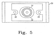
- Figure 5 illustrates a cross-section of the nozzle illustrated in FIG. 4 taken along line 5-5.
- Figure 6 illustrates the hydro-power generation system illustrated in FIG. 4 rotated 90 degrees with a portion of the hydro-power generation system sectioned away.
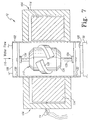
- Figure 7 represents a cross-sectional view of another embodiment of the hydro-power generation system coupled to the water treatment system.
- Figure 8 represents a top view of the embodiment of the hydro-power generation system illustrated in FIG. 7 with a portion of the stator housing sectioned away.
- Figure 9 represents a cross-sectional view of another embodiment of the hydro-power generation system.
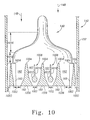
- Figure 10 represents a cross-sectional view of a portion of the hydro-power generation system of FIG. 9.
- Figure 11 represents a side view of another embodiment of the hydro-power generation system.
- Figure 12 represents an end view of a nozzle illustrated in FIG. 11.
- Figure 13 represents a cross-sectional view of the nozzle illustrated in FIG. 12 taken along line 13-13.
- Figure 14 represents another cross-sectional view of the nozzle illustrated in FIG. 12 taken along line 14-14.
- Figure 15 represents a cross-sectional view of a portion of an outer housing of the hydro-power generation system illustrated in FIG. 11 taken along line 15-15.
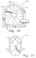
- Figure 16 represents a side view of the hydro-power generation system illustrated in FIG. 11 with an inner housing removed.
- Figure 17 represents a cross-sectional view of a bottom portion of the outer housing of the hydro-power generation system illustrated in FIG. 11 taken along line 17-17.
- Figure 18 represents an exploded perspective view of an inner housing included in the hydro-power generation system illustrated in FIG. 11.
- Figure 19 represents a perspective view of a paddle included in the hydro- power generation system illustrated in FIG. 11.
- Figure 20 represents a cross-sectional view of the paddle illustrated in FIG. 19 taken along line 20-20.
- Figure 21 represents a perspective view of a hydro-power generation system that includes a plumbing fixture.
- Figure 22 represents a cross-sectional side view of the plumbing fixture illustrated in FIG. 21.
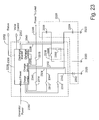
- Figure 23 represents a schematic diagram of an example of a power controller included in the plumbing fixture of FIG. 22.
- Figure 24 represents a schematic diagram of another example of a power controller included in the plumbing fixture of FIG.22.
- Figure 25 is a process flow diagram illustrating operation of the hydro-power generation system within the plumbing fixture of Figs. 21-24.
- Figure 26 represents a partially cross-sectioned side view of another embodiment of the hydro-power generation system.
- Figure 27 represents another cross-sectional side view of the hydro-power generation system of FIG. 26.
- Figure 28 represents a perspective view of a water treatment system.
- Figure 29 represents an exploded perspective view of the water treatment system illustrated in Figure 28.
- Figure 30 represents a perspective view of a valve body included in the water treatment system of Figure 29.
- Figure 31 represents a perspective view of a manifold included in the water treatment system of Figure 29.
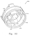
- Figure 32 represents another perspective view of the manifold of Figure 31.
- Figure 33 represents an exploded perspective view of a filter module and a manifold included in the water treatment system illustrated in Figure 29.
- Figure 34 represents an exploded perspective view of a manifold and a reactor vessel included in the water treatment system illustrated in Figure 29.
- Figure 35 represents an exploded perspective view of an elbow included in the reactor vessel illustrated in Figure 34.
- Figure 36 represents a perspective view of the water treatment system illustrated in Figure 28 with a portion of the housing removed.
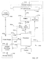
- Figure 37 is a block diagram of a portion of the water treatment system illustrated in Figure 29.
- Figure 38 is a process flow diagram illustrating operation of the water treatment system illustrated in Figure 29.
- Figure 39 is a second part of the process flow diagram of Figure 38.
- Examples of the invention are set forth below with reference to specific configurations, and those skilled in the art would recognize various changes and modifications could be made to the specific configurations while remaining within the scope of the claims. The illustrated embodiments may be used with any system that requires a power supply and includes a waterflow; however, the embodiments are designed for plumbing fixtures, systems such as a water treatment system for residential or portable use, etc. Those skilled in the art would also recognize that the embodiments could be used with liquids other than water and use of the term "water" and "hydro" should not be construed as a limitation.
- FIG. 1 is a side view of a
water treatment system 10 connected with a hydro-power generation system 12. In this embodiment, the hydro-power generation system 12 includes anozzle 14, ahousing 16, animpeller 18 and ahousing outlet 20. Thenozzle 14 is coupled with thewater treatment system 10 by aconduit 22. Theconduit 22 may be formed of PVC plastic or similar material and may be coupled to thenozzle 14 by threaded connection, friction fit or some other similar connection mechanism. - During operation, pressurized water flows from the
water treatment system 10 into the hydro-power generation system 12 via thenozzle 14 as illustrated byarrow 24. Thenozzle 14 is coupled with thehousing 16 such that water flows through thenozzle 14 and is forced through thehousing 16 to thehousing outlet 20. In alternative embodiments, the hydro-power generation system 12 may be positioned within thewater treatment system 10 or positioned to receive a supply of pressurized water before the water enters thewater treatment system 10. - FIG. 2 illustrates a cross section of one embodiment of the
nozzle 14. Thenozzle 14 is a sonic nozzle that increases the velocity of pressurized water flowing therethrough. In this embodiment, thenozzle 14 is capable of increasing the velocity of the water to sub-sonic speed. Thenozzle 14 is formed of stainless steel or some other similar rigid material and includes anozzle inlet 26 and anozzle outlet 28. Thenozzle inlet 26 is coupled to thewater treatment system 10 as previously discussed. Thenozzle outlet 28 is coupled to thehousing 16 by friction fit, snap-fit, threaded connection or some other similar coupling mechanism capable of forming a watertight connection therebetween. Thenozzle 14 may penetrate thehousing 16 in any location that provides proper alignment of thenozzle 14 with the impeller18 as will be hereinafter discussed. - The
nozzle 14 includes apassageway 30 that provides for the flow of water therethrough. Thepassageway 30 is formed to be a firstpredetermined diameter 32 at thenozzle inlet 26 and a secondpredetermined diameter 34 at thenozzle outlet 28. In this embodiment, the secondpredetermined diameter 34 is about twenty-six percent of the firstpredetermined diameter 32. Thepassageway 30 remains the firstpredetermined diameter 32 for a predetermined length of thenozzle 14. The remaining portion of thepassageway 30 is conically shaped by uniformly tapering thepassageway 30 to the secondpredetermined diameter 34. In this embodiment, thepassageway 30 of thenozzle 14 tapers at an angle of approximately 18 degrees between the firstpredetermined diameter 32 and the secondpredetermined diameter 34. - The configuration of the
passageway 30 determines the velocity of the water exiting from thenozzle 14. In addition, the velocity of the water at thenozzle outlet 28 is dependent on the pressure of the water source and the back pressure downstream of thenozzle 14. A desirable predetermined range of the velocity at thenozzle outlet 28 may be determined using an expected range of pressure provided by the water treatment system 10 (illustrated in FIG. 1) at thenozzle inlet 26. For example, in a household water system, the pressure of the water supply is in a range of about twenty to sixty pounds-per-square-inch (PSI). Thepassageway 30 also provides a continuous and uniform stream of water at thenozzle outlet 28. During operation water flowing through thenozzle 14 flows into thehousing 16 within a predetermined range of velocities and with a predetermined trajectory. - Referring back to FIG. 1, the
housing 16 forms a conduit that may be composed of plastic or some other similar waterproof material capable of forming a rigid passageway for water. In this embodiment, thehousing 16 includes a translucent portion as illustrated in FIG. 1 to allow viewing of the interior of thehousing 16. Thehousing 16 is formed to encompass theimpeller 18 that is in fluid communication with water as the water flows through thehousing 16 after exiting thenozzle outlet 28. - The
impeller 18 includes a plurality ofblades 42 that are rigidly fastened to ahub 44. Theblades 42 are positioned in thehousing 16 such that water flowing from thenozzle 14 impinges upon theblades 42 of theimpeller 18 at a predetermined angle. The predetermined angle is determined based on the expected pressure of the water at thenozzle inlet 26, the back pressure at thenozzle outlet 28 and the desired revolutions-per-minute (RPM) of theimpeller 18. During operation, the flowing water acts on theimpeller 18 causing it to rotate in a single direction within thehousing 16. As discussed in detail below, as theimpeller 18 rotates, this embodiment of the hydro-power generation system 12 converts the energy in the flowing water to rotational energy, which is then converted to electricity. In this embodiment, theimpeller 18 is submerged in the water flowing through thehousing 16. - FIG. 3 illustrates the embodiment depicted in FIG. 1 rotated 90 degrees with a portion of the
housing 16 sectioned away. As illustrated, theimpeller 18 is coaxially fastened to agenerator 46 by a longitudinal extendingshaft 48. Theshaft 48 may be stainless steel or some other similar rigid material that is fixedly coupled with theimpeller 18. Thehub 44 of theimpeller 18 is coaxially coupled to one end of theshaft 48 and agenerator shaft 50, which is part of thegenerator 46, is coaxially coupled to the other end. The rigid coupling of theshaft 48 to theimpeller 18 and thegenerator 46 may be by welding, press-fit or other similar rigid connection. - The
rotatable shaft 48 longitudinally extends to penetrate thehousing 16 through awatertight seal 52 made of rubber or other similar material. Thewatertight seal 52 is coupled to thehousing 16 and is formed to allow theshaft 48 to rotate freely without the escape of water from within thehousing 16. Theshaft 48 longitudinally extends to thegenerator 46 that is positioned adjacent thehousing 16. Although not illustrated, the outer surface of thegenerator 46 may be coupled to thehousing 16 by, for example, nuts and bolts, rivets or other similar mechanism capable of fixedly coupling thehousing 16 andgenerator 46. - During operation, as water flows through the
housing 16 and theimpeller 18 rotates,shafts generator 46. In an alternative embodiment, a magnetic coupler (not shown) is used in place of theshaft 48 to eliminate the need for penetration of thehousing 16. In this embodiment, theimpeller 18 includes magnets with sufficient magnetic strength to rigidly couple with similar magnets positioned on thegenerator shaft 50 outside thehousing 16. During operation, when theimpeller 18 rotates, the magnetic attraction of the magnets oriented on the impeller and the magnets oriented on thegenerator shaft 50 cause rotation of thegenerator shaft 50 thereby generating electricity from thegenerator 46. - In this embodiment, the
generator 46 may be a permanent magnet generator capable of generating alternating current (AC). The alternating current (AC) may be rectified to produce direct current (DC). In an alternative embodiment, thegenerator 46 may be capable of generating both AC and DC current. The electricity is transferred from thegenerator 46 by a plurality ofconductors 54 that may be wires, busses or other similar materials capable of conducting electricity. The voltage level of the electricity produced is a function of the revolutions-per-minute of theimpeller 18. As previously discussed, the velocity of the water flowing from thenozzle 14 may be designed within a predetermined range thereby controlling the voltage output of the electricity generated by thegenerator 46. - The alternating current or rectified direct current produced by this embodiment may be used to power the
water treatment system 10 and may also be used to charge an energy storage device (not shown) such as, for example, a battery or capacitors. The rotation of the impeller18 or the duration of the electricity being produced may also provide a mechanism for flow-based measurements such as, flow rates or the quantity of water that has flowed through thewater treatment system 10. The rotation of theimpeller 18 or the duration of the electricity being produced may be combined with the back electromagnetic force(EMF) of thegenerator 46 to provide the flow- based measurements. Those skilled in the art would recognize that the hydro-power generation system 12 may also be used in other systems besides thewater treatment system 10. - FIG. 4 illustrates a cross sectional view of another embodiment of the hydro-
power generation system 12. This embodiment is similarly coupled to thewater treatment system 10 as in the embodiment illustrated in FIG. 1 and includes anozzle 14, ahousing 16, animpeller 18 and ahousing outlet 20. Similar to the previously discussed embodiment, thenozzle 14 provides water at high velocity that is directed at therotatable impeller 18. However, in this embodiment, theimpeller 18 is not submerged in water within thehousing 16 during operation. As such, the water from thenozzle 14 forms a stream that is directed at theimpeller 18. - The
nozzle 14 may be a sonic nozzle similar to the previously discussednozzle 14 illustrated in FIG. 2. Thenozzle 14 penetrates thehousing 16 and is coupled thereto by a mountingplate 56. The mountingplate 56 is positioned adjacently contacting the outer surface of thehousing 16. Those skilled in the art would recognize that other methods exist that could be used to couple thenozzle 14 with thehousing 16. - FIG. 5 illustrates a cross sectional view of the
nozzle 14 mounted in the mountingplate 56 of this embodiment. The mountingplate 56 includes alongitudinal slot 58 and a pair ofears 60 that allow adjustment of thenozzle 14 to an optimal position in relation to theimpeller 18. In this embodiment, thenozzle 14 may be fixedly mounted to thehousing 16 when the optimal position is achieved by inserting threaded screws in theears 60. In alternative embodiments, the mountingplate 56 provides a single predetermined desired position of thenozzle 14 when the fasteners such as, for example, threaded screws, rivets or pins fixedly mount the mountingplate 56 on thehousing 16. - Referring again to FIG. 4, the desired position of the
nozzle 14 is such that thenozzle 14 longitudinally extends into thehousing 16. Thehousing 16 of this embodiment includes ahousing cavity 62 that is defined by the inner walls of thehousing 16 as illustrated in FIG. 4. Thehousing cavity 62 is an air space that includes theimpeller 18 positioned therein. During operation, water is discharged from thenozzle 14 into thehousing cavity 62 with a predetermined trajectory to strike theimpeller 18 at a predetermined angle. The predetermined angle is based on the desired RPM of theimpeller 18 and the range of the pressure of water supplied to thenozzle 14 from thewater treatment system 10. The cooperative operation of thenozzle 14 and theimpeller 18 are not limited to operation with pressurized water and other fluids such as, for example, air could similarly be utilized. - As further illustrated in FIG. 4, the
impeller 18 includes a plurality ofblades 64. Each of theblades 64 of this embodiment are fixedly coupled to animpeller hub 66 at one end and include apaddle 68 formed at the opposite end. Theimpeller hub 66 is fixedly coupled to ashaft 48 as in the previously discussed embodiments. Those skilled in the art would recognize that the quantity of theblades 64 and the size of theimpeller 18 could vary depending on the application. - FIG. 6 illustrates the embodiment hydro-
power generation system 12 illustrated in FIG. 5 rotated 90 degrees with a portion of thehousing 16 sectioned away for illustrative purposes. As illustrated, the hydro-power generation system 12 includes thehousing 16 coupled to thegenerator 46 with theshaft 48 as in the previously discussed embodiments. In addition, theshaft 48, which is rotatable, longitudinally extends from theimpeller 18 into thegenerator 46 through thewatertight seal 52. In an alternative embodiment, theshaft 48 could be modified with a magnetic coupler, as previously described, thereby eliminating the penetration of thehousing 16 and thewatertight seal 52. As illustrated, the shaft48 rotatably positions the impeller18 in the airspace within thehousing cavity 62 with the paddles68 thereby rotating about theshaft 48. - As illustrated in FIG. 6, each of the
paddles 68 of this embodiment are formed in a parabolic shape that includes aslot 70. The parabolic shape of thepaddles 68 provide a uniform receiver of the energy present in the water discharged from the nozzle 14 (illustrated in FIG. 5). Theslots 70 allow the energy of the discharged water to pass to thenext paddle 68 as theimpeller 18 rotates. The transitional passing of the energy in the discharged water to thenext paddle 68 maximizes the efficiency of the energy transfer from the water to theimpeller 18. In alternative embodiments, theblades 64 could be formed in other shapes and configurations that are conducive to the efficient transfer of energy from other fluids discharged from thenozzle 14. For example, when the fluid is air, theblades 64 may be formed as vanes, fins or other similar structure capable of translating the energy from the flowing air to the rotation of theimpeller 18. - During operation, after the stream of water strikes the
impeller 18 at a predetermined angle, the water falls by gravity as indicated byarrow 72 toward thehousing outlet 20. As such, the water collects at thehousing outlet 20 and is thereby channeled out of thehousing 16. Since theimpeller 18 is not submerged in water, the bulk of the energy transferred from the water stream to theimpeller 18 is provided as rotational force to theshaft 48. - The rotation of the
shaft 48 causes rotation of a portion of thegenerator 46. One embodiment of thegenerator 46 includes arotor 76, afirst stator 78, and asecond stator 80 positioned within agenerator housing 82. Therotor 76 is fixedly coupled to theshaft 48 and rotates therewith. The first andsecond stators generator housing 82 and circumferentially surround the shaft48. Therotor 76 is positioned between the first andsecond stators generator 46. - The
rotor 76 of this embodiment may be in the form of a disk that includes a plurality ofpermanent magnets 84. Thepermanent magnets 84 are uniformly place in predetermined positions within therotor 76 to operatively cooperate with the first andsecond stators second stators coils 86. Thecoils 86 are positioned uniformly within the first andsecond stators permanent magnets 84. Thecoils 86 may be electrically connected to form one or more windings that are operable to generate electricity. The number of poles and the design of the first andsecond stators permanent magnets 84 and the back EMF, as well as the desired RPM and the desired power output of thegenerator 46. - In this embodiment, the rotation of the
rotor 76 causes magnetic flux that is generated by thepermanent magnets 84 to similarly rotate thereby producing electricity in the first andsecond stators rotor 76 and the first andsecond stators generator 46 to supply both AC and direct current (DC). In an alternative embodiment, thepermanent magnets 84 may be positioned on the first andsecond stators generator 46 is operable to generate direct current (DC). In another alternative embodiment, thegenerator 46 is similar to thegenerator 46 discussed with reference to FIG. 3. - During operation, pressurized water may be supplied from the water treatment system 10 (illustrated in FIG. 1) to the hydro-
power generation system 12. As in the previous embodiments, alternative embodiments of the hydro-power generation system 12 may supply water to thewater treatment system 10 or be positioned within thewater treatment system 10. In this embodiment, water is supplied from thewater treatment system 10 to thenozzle 14 as previously discussed. - Pressurized water flows through the
nozzle 14 and discharges with high velocity into thehousing cavity 62 thereby striking thepaddles 68 on theimpeller 18 at a predetermined angle of incidence. When the water strikes thepaddles 68, the energy in the discharged water is translated to theimpeller 18 causing rotation in a single direction. As theimpeller 18 rotates, a portion of the discharged water stream also streams through theslots 70 and strikes another of thepaddles 68 on theimpeller 18. Following the collision of the water with thepaddles 68 and the accompanying transfer of energy, the water falls by gravity to thehousing outlet 20 and flows out of thehousing 16. Accordingly, thehousing cavity 62 remains an air space during operation and is not completely filled with water during operation. - The rotation of the
impeller 18 causes rotation of theshaft 48 thereby rotating therotor 76 of thegenerator 46. In this embodiment, therotor 76 rotates at about 2400 revolutions-per-minute (RPM). Rotation of therotor 76 induces the generation of electricity that is supplied to thewater treatment system 10. As previously discussed, the range of the voltage level produced by thegenerator 46 is based on the range of velocity of the water flowing through thenozzle 14. Accordingly, the voltage range of the generator can be selected by selecting a predetermined range of velocity for the flowing water through thenozzle 14. - FIG. 7 illustrates a cross-sectional view of another embodiment of the hydro-
power generation system 12 which is preferentially coupled with thewater treatment system 10. As illustrated, the hydro-power generation system 12 includes arotor housing 102 and astator housing 104. Therotor housing 102 forms a conduit that may be composed of plastic or other similar rigid material and includes aninlet 106 and anoutlet 108. During operation theinlet 106 receives the flowing water as illustrated byarrow 110 and theoutlet 108 channels the flowing water to thewater treatment system 10. In alternative embodiments, the hydro-power generation system 12 may be positioned within thewater treatment system 10 or positioned to receive water flowing out of thewater treatment system 10. As previously discussed, the flow of water through the hydro-power generation system 12 may be controlled by thewater treatment system 10. - As illustrated in FIG. 7, the
rotor housing 102 contains arotor 112 and thestator housing 104 contains astator 114. Therotor 112 of this embodiment may be a twelve-pole permanent magnet rotor having six north/south pole combinations. As set forth in detail below, thestator 114 of this embodiment may be an annular ring designed with eight north/south pole combinations. Therotor 112 and thestator 114 cooperatively operate to produce electricity during operation. As known in the art, a stator contains a stationary winding that can be configured to contain any number of poles depending on the magnitude of the voltage needed at the output. The number of poles in the winding disclosed in the present embodiment should not be construed as a limitation on the present invention. - FIG. 8 illustrates a top view of the embodiment depicted in FIG. 7 with the top portion of the
stator housing 104 sectioned away for illustrative purposes. Thestator 114 is fixedly positioned in thestator housing 104 to circumferentially surround therotor housing 102. Thestator 114 includes a core 116, a plurality ofsalient poles 118 and a plurality ofcoils 120. The core 116 may be composed of iron, steel or other similar material and is formed to include thesalient poles 118. In this embodiment, there may be eightsalient poles 118 that are each surrounded bycoils 120. - The
salient poles 118 are formed on thestator 114 such that they circumferentially surround therotor housing 102. Each of thesalient poles 118 includes a formed end that is known in the art as apole shoe 122. The pole shoes 122 are located adjacent therotor housing 102. The pole shoes 122 conduct a constant magnetic flux formed by therotor 112 through thecoils 120. Thecoils 120 may be wire or some other similar material capable of conducting electricity and being wrapped around thesalient poles 118. Although not illustrated, thecoils 120 are electrically connected to form the winding. As known in the art, the number of turns of wire used for eachcoil 120 is determined by the voltage and power requirements, the minimum and maximum revolutions of therotor 112, the maximum allowable back-pressure, the required inductance and the magnetic gauss. - Referring again to FIG. 7, the
stator 114 is transversely positioned perpendicular to the central axis of therotor housing 102. Since thestator 114 is positioned outside therotor housing 102, it is isolated from fluid communication with the water flowing within therotor housing 102. Thestator housing 104 is fixedly coupled to therotor housing 102 thereby providing a predetermined position on therotor housing 102 for thestator 114. In this embodiment, thestator housing 104 is coupled with the external surface of therotor housing 102 by a friction fit. Those skilled in the art would recognize that various other ways of coupling therotor housing 102 and thestator housing 104 exist. - In this embodiment of the hydro-
power generation system 12, therotor 112 includes apermanent magnet 124 that can be formed of metal, sintered metal, extruded metal, plastic injected or ceramic material. Thepermanent magnet 124 forms a constant magnetic flux and is coupled with arotor shaft 126. Therotor shaft 126, which is rotatable, longitudinally extends from opposite ends of thepermanent magnet 124 and may be composed of stainless steel or other rigid, corrosion resistant material. Thepermanent magnet 124 is formed with its central axis coaxial with therotor shaft 126. The outer surface of thepermanent magnet 124 may be formed in a streamline shape to include at least onerotor blade 128. Thepermanent magnet 124 of this embodiment is formed in a barrel shape with a single helical ridge forming the rotor blade128. In alternative embodiments, therotor blade 128 could be turbine blades or other similar devices capable of inducing rotation of therotor 112 when subjected to flowing water. - As illustrated in FIG. 7, the
rotor 112 is positioned within therotor housing 102 coaxial with the central axis of therotor housing 102. One end of therotor shaft 126 of therotor 112 is inserted in afirst collar 130 and the other end of therotor shaft 126 is inserted in asecond collar 132. In this embodiment, the ends of therotor shaft 126 increase in diameter to form a solid sphere to facilitate fastening to thefirst collar 130 and thesecond collar 132. Thefirst collar 130 and thesecond collar 132 are formed of plastic or other similar material and create a transverse strut perpendicular to the central axis of therotor housing 102. Thefirst collar 130 and thesecond collar 132 each contain abearing 134 or other similar device to allow therotor shaft 126 to rotate freely. Additionally, thefirst collar 130 and thesecond collar 132 are coupled to therotor housing 102 at a predetermined distance from each other such that therotor 112 can be suspended therebetween. - The
rotor 112 is positioned in therotor housing 102 such that water flowing through therotor housing 102 impinges upon therotor blade 128 that forms a part of therotor 112. Therotor blade 128 acts as a paddle, causing the flowing water to act on therotor 112. The flowing water causes therotor 112 to rotate in a single direction about the central axis of therotor housing 102. Therotor 112 is positioned within thestator 114 such that the axis of therotor 112 is concentric with that of thestator 114. Therotor 112 operatively cooperates with thestator 144 to form the generator. - During operation, as water is flowing and the
rotor 112 is rotating, the constant magnetic flux generated by therotor 112 also rotates and penetrates into thestator 114 thereby intrinsically creating power. An air gap of a specified distance must be maintained between therotor 112 and thestator 114 to allow the constant magnetic flux from therotor 112 to induce the generation of electricity from thestator 114. In these embodiments, the "air gap" between thepermanent magnet 124 of therotor 112 and the pole shoes 122 of thestator 114 consists of flowing water and therotor housing 102. The flow of fluid and therotor housing 102 do not affect the constant magnetic flux. Accordingly, the rotating constant magnetic flux from therotating rotor 112 induces the production of electricity from thecoils 120 of thestator 114. - As the water flows through the
rotor housing 102 causing therotor 112 to rotate, the rotating constant magnetic flux is imparted on the winding of thestator 114 and electricity is produced. The electricity flows throughconductors 54 to power a device which is awater treatment system 10 in this embodiment. The hydro-power generation system 12 of this embodiment illustrated in Figs. 7 and 8 produces alternating current (AC) that may be used to power thewater treatment system 10. In an alternative embodiment, the hydro-power generation system 12 may rectify the alternating current (AC) to produce direct current(DC). In another alternative embodiment, the hydro-power generation system 12 supplies both AC and DC current to thewater treatment system 10 by rectifying and stabilizing the alternating current (AC). The DC current may also be used to charge an energy storage device (not shown). The rotation of therotor 112 and the duration that electricity is produced may also be used to provide flow-based measurements such as, the flow rate or the quantity of water flowing through thewater treatment system 10. - FIG. 9 illustrates a cross-sectional view of yet another embodiment of the hydro-
power generation system 12 that is similar in concept to the previous embodiment disclosed with respect to Figs. 7 and 8. This embodiment includes arotor 112, astator 114 and aturbine nozzle 140 positioned in ahousing 142. Thehousing 142 forms a conduit that includes aninlet 144 and anoutlet 146. As water or some other fluid flows into theinlet 144 as illustrated byarrow 148, the water flows through thehousing 142 and is channeled out of thehousing 142 by theoutlet 146. In one embodiment, the hydro-power generation system 12 may be positioned within a water treatment system 10 (illustrated in FIG. 1), following thewater treatment system 10 or supplying water to the water treatment system 1 O. - The
housing 142 may be formed of plastic or similar rigid material capable of channeling water. Thehousing 142 of this embodiment includes afirst section 152 and asecond section 154 to facilitate assembly and maintenance. The first and second sections 152,154 may be fixedly coupled by gluing, friction fit, threaded connection, sonic welding or some other means of providing a similar rigid connection. Thehousing 142 forms apassageway 156 for the flow of water therethrough. Fixedly positioned within thepassageway 156 is theturbine nozzle 140. - The
turbine nozzle 140 of this embodiment may be generally conical in shape and may be formed of plastic or some other similar rigid material. Theturbine nozzle 140 may be integrally formed to include a tip158 and a plurality ofstruts 160. Thetip 158 may be centrally located in thepassageway 156 and serves to direct the flowing water outwardly toward the inner wall of thehousing 142. Thestruts 160 are fixedly coupled to the inner wall of thehousing 142 by, for example friction fit, snap- fit, threaded connection or other similar rigid connection. - The
struts 160 fixedly hold theturbine nozzle 140 in thepassageway 156 and include a plurality ofchannels 162 to allow water to flow through thehousing 142. The size of thechannels 162 may be adjusted to control the velocity of the flowing water. As in thenozzle 14, previously discussed with reference to FIG. 2, a predetermined range of velocity can be determined. The predetermined range of velocity is based on the expected pressure range of the water flowing in theinlet 144 as well as the backpressure of the hydro-power generation system 12. In addition, thestruts 160 may be oriented in a predetermined configuration to act as vanes to direct the flowing water. The flowing water may be directed, for example, to act upon therotor 112 in a predetermined way, to eliminate turbulence, to adjust pressure drop or to increase the efficiency of operation. - FIG. 10 is cutaway top view of a portion of the hydro-
power generation system 12 of FIG. 9 illustrating thenozzle 140 and thestruts 160 within thefirst section 152 of thehousing 142. Thestruts 160 may be positioned at adetermined distance 1002, such as 4.42 millimeters (0.174 inches) from each other around the outside of thenozzle 140 to form thechannels 162. Each of thestruts 160 includes aleading end 1004 and a trailingend 1006. Theleading end 1004 of adjacently locatedstruts 160 may form an entry duct, and the trailingend 1006 of adjacently locatedstruts 160 may form an exit duct. The flow of liquid, as indicated byarrow 148, first reaches theleading end 1004 and enters the entry duct. Within thechannels 162, the liquid is increased in velocity prior to reaching the trailingend 1006 of thestruts 160. - The width of the
channels 162 may become gradually narrower toward the trailingend 1006 as illustrated. As such, the cross-sectional area between the channels is reduced by a predetermined amount such as about 10% to 20%. Since the pressurized liquid is forced into an increasinglynarrower channel 162, velocity increases. The gradual reduction in cross-sectional area between thechannels 162 minimizes back pressure while increasing the velocity of the flowing liquid. In addition, non-laminar flow of liquid within thechannels 162 is minimized by the gradually narrowingchannels 162. - The
struts 160 may also include a plurality offlow straightners 1008. The flow straightners 1008 may be included in thechannels 162 to further minimize non- laminar flow. Similar to thestruts 160, theflow straightners 1008 may be fixedly coupled with the inner wall of thefirst section 152 and extend into thechannels 162. The example flow straightners 1008 may include a blade1010 coupled with abody 1012. Theblade 1010 may be a substantially straight section of the flow straightners 1008 that extends from near theleading end 1004 toward the trailingend 1006 of each of thestruts 160. Thebody 1012 may be spherical shaped body that is positioned a determined distance upstream of the exit duct formed by the trailing ends 1006 of the adjacently positioned struts 160. In other examples, theflow straightners 1008 may be any other hydrodynamic shape to define the flow of liquid and maximize uniform flow thorough thechannels 162. - As further illustrated in FIG. 10, the
nozzle 140 may be divided into acompression region 1016 followed by asettlement region 1018. Within thecompression region 1016, an abrupt transition in the direction of flow of the liquid may occur. The abrupt transition may increase turbulence in the flow of liquid. Turbulence may increase as the volume of liquid capacity within thefirst section 152 decreases. As the volume decreases, compression and the velocity of the liquid increase. The decrease in volume in thecompression region 1016 may be predetermined to achieve a desired flow rate based on the expected pressure range of the flowing liquid. Within thecompression region 1016, the flowing liquid is forced outward toward the inner wall of thehousing 142 which may increase turbulence and/or non-laminar flow. - The settlement region1018 provides an area with a uniform volume of liquid capacity that allows turbulence in the flowing liquid to subside and the liquid to have a more laminar flow. The
settlement region 1018 may be a predetermined length based on the projected amount of turbulence in the flowing liquid. Non-laminar flow of the liquid may be reduced prior to entering thechannels 162. Within thechannels 162, the velocity of the flowing liquid is further increased, and the liquid is then directed to therotor 112. - Referring again to FIG. 9, the
rotor 112 of this embodiment includes aturbine rotor 164, arotor shaft 166 and apermanent magnet 168. Therotor 112 is rotatably positioned within thepassageway 156 such that water flowing in thepassageway 156 causes rotation of therotor 112 about acentral axis 170 of thehousing 142. Rotation of therotor 112 occurs when the flowing water acts upon theturbine rotor 164. Theturbine rotor 164 may be formed of stainless steel, aluminum, plastic or other similar rigid material that is capable of withstanding the rotational forces and the force of the flowing water. Theturbine rotor 164 includes at least oneturbine blade 172 and abody 174. - The
turbine blade 172 is positioned to receive energy from water flowing through thestruts 160. Theturbine blade 172 may be a plurality of vanes, a helical ridge or other mechanism formed on thebody 174 that is capable of converting the energy of the flowing water to rotational energy. Theturbine blade 172 of this embodiment is integrally formed with thebody 174 and extends until positioned adjacent the inner wall of thehousing 142. Thebody 174 may be formed to define acavity 176 that circumferentially surrounds a portion of therotor shaft 166. - It should be noted by the reader that the depth of the
channels 162 are less than the depth of theturbine blade 172 with respect to the inner wall of thehousing 142. The differential depth provides circulation of the flowing water as will be hereinafter discussed. In addition, the flow path of the water is substantially straight past thestator 114. The volume of the flow path is also larger following thechannels 162 to provide a determined drop in pressure of the flowing water. The flowing water therefore discharges substantial amounts of kinetic energy to therotating turbine blade 172 as the water flows past theturbine blade 172. The kinetic energy in the flowing water is efficiently extracted by theturbine blades 172 without significant losses and inefficiencies since only theturbine blades 172 are directly in the high velocity stream of flowing water. - The
rotor shaft 166 is rotatable and may be integrally formed with theturbine rotor 164 or, therotor shaft 166 may be fixedly coupled thereto by press-fit, threaded connection or similar coupling mechanism. Therotor shaft 166 may be stainless steel or other similar rigid material that may longitudinally extend through thepermanent magnet 168. Thepermanent magnet 168 may be an extruded magnet or plastic injected magnet. Alternatively, the permanent magnet may be formed of metal, sintered metal, ceramic material or some other similar material with magnetic properties. Thepermanent magnet 168 may be fixedly coupled to therotor shaft 166 by friction fit, molding or other similar mechanism. Therotor 112 is rotatable held in position by a plurality ofbearings 178. - The
bearings 178 circumferentially surround a portion of therotor shaft 166 at opposite ends of thepermanent magnet 168. Thebearings 178 may be carbon graphite, Teflon, ball bearings, ceramic, ultra high molecular weight (UHMW) polyethylene or other similar bearings capable of withstanding the rotation of therotor shaft 166. In this embodiment, thebearings 178 are lubricated by water present in thepassageway 156. In addition, the flowing water is operable to cool thebearings 178 as will be hereinafter described. Thebearings 178 are fixedly coupled and held in position by thestator 114. - The
stator 114 of this embodiment includes a plurality of exit guide vanes180, afin 182, a plurality ofcoils 184 and a cap186. As illustrated in FIG. 9, thestator 114 is fixedly positioned in thepassageway 156 by the exit guide vanes 180. Theexit guide vanes 180 are fixedly coupled with the inner wall of thehousing 142 by, for example, glue, friction fit, snap fit or similar rigid coupling mechanism. Theexit guide vanes 180 longitudinally extend parallel with the inner wall of thehousing 142 and provide channels for the flow of water therethrough. Theexit guide vanes 180 are formed to channel the flowing water to theoutlet 146 to reduce turbulence, air bubbles, back pressure and other similar behavior of the flowing water that may effect efficient operation. Thefin 182 is similarly formed to channel the flowing water to theoutlet 146. - Although not illustrated, the
exit guide vanes 180 may be formed in a swirl pattern that resembles a helically shaped coil (or rifling) that is concentric with thecentral axis 170. Theexit guide vanes 180 may gradually un-coil in the direction of thefin 182 to eventually become substantially parallel with thecentral axis 170. In this configuration, theexit guide vanes 180 may reduce turbulence and create a laminar flow. - During operation, liquid received by the
exit guide vanes 180 may include a swirling tendency due to the rotation of theturbine blade 172. The swirling tendency in the liquid may substantially match the swirl pattern of the exit guide vanes180. Accordingly, the liquid enters theexit guide vanes 180 without abrupt directional changes that can cause turbulence. While being channeled by theexit guide vanes 180, the swirling tendency in the liquid may be gradually minimized by the gradual un-coiling of the exit guide vanes 180. Thus, the liquid may exit theexit guide vanes 180 with a substantially laminar flow to maximize efficient operation. - The
coils 184 are formed on a core (not shown) to circumferentially surround therotor 112 and form a winding. Thecoils 184 are separated from therotor 112 by anair gap 188. Thecoils 184 are fixedly coupled with the exit guide vanes 180. In addition, thecoils 184 may be fixedly coupled with thebearings 178 and thefin 182. Thecoils 184 may be fixedly coupled to theexit guide vanes 180, thebearings 178 and thefin 182 by, for example, glue or by being integrally formed therewith. In this embodiment, thecoils 184 are positioned within thepassageway 156, but are waterproof to avoid fluid communication with the flowing water. Thecoils 184 may be made waterproof by being, for example, potted with epoxy, injection molded with rubber or plastic, ultrasonically sealed or otherwise isolated from the water by a similar waterproofing mechanism. In an alternative embodiment, thecoils 184 may be located outside thehousing 142 as in the embodiment previously discussed with reference to Figs. 7 and 8. - The
coils 184 are also water proofed by thecap 186. Thecap 186 is positioned to seal the end of thecoils 184 that is adjacent theturbine rotor 164 as illustrated in FIG. 9. Thecap 186 may be removably coupled to thecoils 184 by threaded connection or may be fixedly coupled to thecoils 184 by glue or integral formation therewith. Thecap 186 is formed to partially surround thebearing 178 and radially extend a predetermined distance that is equal to the radius of thestator 114. The predetermined distance of thecap 186 extends closer to the inner wall of thehousing 142 than thebody 174 of theturbine rotor 164. The difference in the distance from the inner wall of thehousing 142 to thecap 186 and thebody 174 provides for circulation of the flowing water as will be hereinafter discussed. - During operation, water flowing through the
inlet 144 and into thepassageway 156 experiences a predetermined increase in velocity as the pressurized water flows through thechannels 162. The flowing water is directed by thestruts 160 to achieve a predetermined angle of incidence on theturbine blade 172 that imparts rotation on therotor 112. Due to the differential depth of thechannel 162, theturbine blade 172 and thecap 182, the flowing water is circulated into thecavity 176. Circulation of the flowing water through thecavity 176 provides cooling and lubrication of the adjacently positionedbearing 178. - In this embodiment, the
rotor 112 rotates above about 5,000 revolutions-per- minute (RPM), such as in a range of between about 5,000 RPM and about 10,000 RPM or in a range between about 4,000 RPM and about 12,000 RPM. Rotation above about 5,000 RPM may be based on a liquid flow rate of about 3.78 liters/minute to about 11.35 liters/minute (about 1 to 3 gallons/minute) in a liquid pressure range of about 415 kPa to about 690 kPa (about 60 to 1001bs/sq. inch). Rotation above about 5,000 RPM may also be based on a liquid flow rate of about. 76 liters/minute to about 3.781iters/minute (about 0.2 to about 1 gallons/minute) in a liquid pressure range of about 103.4 kPa to about 415 kPa (about 15 to 60 PSI). Depending on the physical properties of the liquid and/or manufacturing tolerances, the dimensions, the RPM, the pressure and the flow rates discussed herein may vary by as much as 10% to 20%. - To operate in this RPM range, the hydro-power generation system may be miniaturized to reduce inefficiency due to fluid impedance (or windage losses). As used herein, the term"fluid impedance"is defined as fluid friction and/or any other fluid effects that may compromise maximization of the transfer of kinetic energy to rotational energy.
- Miniaturization of the hydro-power generation system minimizes surface areas that are subject to fluids as the
rotor 112 rotates. In addition, the weight of the hydro- power generation system is minimized. For example, the diameter of thepassageway 156 may be in a range of about 6.35 millimeters to about 51 millimeters (about. 25 inches to about 2 inches). In addition, the depth of thechannels 162 may be about. 76 millimeters to about 2.54 millimeters (about. 03 inches to about. 1 inches) and the depth of theturbine blade 172 may be about. 89 millimeters to about 3. 8 millimeters (about. 035 inches to about. 15 inches. - The higher RPM that is achievable due to the miniaturization and fluid impedance reductions maximizes power generation efficiency. For example, the generator may produce between about. 27 and 30 watts when rotating between about 5,000 and 10,000 RPM. In addition, the size (and weight) of the
permanent magnet 168 may be dimensioned to optimize the power production of the hydro-power generation system 12. - The high RPM revolution of the
rotor 112 within thestator 114 efficiently produces electricity when the hydro-power generation system 12 is operating. The hydro-power generation system 12 is capable of generating alternating current (AC). In alternative embodiments, the hydro-power generation system 12 may produce (DC) current. In another alternative embodiment, the hydro-power generation system 12 may be designed to produce both AC current and DC current by rectification and stabilization of the AC current. As previously discussed, the number of poles and the size and configuration of thecoils 184 is dependent on the back pressure, the required RPM's and the target energy output of the hydro-power generation system 12. - Referring now to Figs. 3,6, 7,8 and 9, another embodiment of the hydro-
power generation system 12 discussed in conjunction with the embodiments of these figures is operable to supply multiple voltage and current levels. The multiple voltage and current levels are supplied by switching the coils of the hydro-power generation system 12 between a series configuration and a parallel configuration. Although not illustrated, a microprocessor or other similar control unit that can sense the voltage and current output of the hydro-power generation system 12 and the present voltage and current needs of thewater treatment system 10 may be used to selectively switch the coils between series and parallel configurations. Alternatively, RPM may be used to selectively switch the coils. Selective switching of the coils may be applied to embodiments that produce direct current (DC) or alternating current(AC). - For example, some ultraviolet (UV) light sources require a relatively low predetermined alternating current for initial energization and a relatively high voltage level. Following initial energization, the W light source requires a relatively high alternating current but requires a relatively low voltage level to remain energized. In a water treatment system for example, the UV light source may be a low pressure mercury lamp or a cold cathode lamp and the starting voltage and the running state voltage may be provided by a ballast. Alternatively, the hydro-
power generation system 12 may provide a ballast function as described below and the ballast may be eliminated. The mercury lamp and/or the cold cathode lamp may remove bacteria and other impurities from water. - During operation, when the hydro-
power generation system 12 is generating electricity, the coils may be selectively placed in a series configuration by the microprocessor. The series configuration generates a predetermined alternating current at a predetermined voltage level that is capable of initially energizing the UV light source with the startup voltage. Following initial energization of the UV light source, the coils are selectively reconfigured to a parallel configuration to provide a predetermined alternating current at a predetermined voltage level capable of maintaining energization of the UV light source with the running state voltage. Switching the coils of the hydro-power generation system 12, as previously discussed, may provide for various voltage and current requirements of any electrical device in any system supplied power by the hydro-power generation system 12. - In another embodiment, the hydro-
power generation system 12 discussed in conjunction with the previously discussed embodiments may be provided with a plurality of taps representing different groups of coils formed into windings. The taps are operable to supply a plurality of different predetermined voltage levels by electrically connecting different numbers of coils to form the windings. Thewater treatment system 10 may be configured to operatively switch between the taps during operation using a microprocessor or some other similar device. Accordingly, in the UV light source example previously discussed, one tap may be used for initial energization to provide the startup voltage and another tap may be used for continuous operation to provide the running state voltage. In addition, different taps may be used on an ongoing basis to operate different electrical devices in thewater treatment system 10 depending on the power requirements of the electrical devices. Tap switching may also be used to control the RPM of the generator. Where the RPMs are below a desired threshold, for example, taps may be adjusted to drop coils out thereby increasing the RPM. Tap switching of the hydro-power generation system 12 may also provide various voltage levels for any system supplied power by the hydro-power generation system 12. - In yet another embodiment of the hydro-
power generation system 12 discussed in conjunction with the previously discussed embodiments, the back electromagnetic force (EMF) that is present is advantageously reduced. As known in the art, the back EMF of a permanent magnet generator is increased by flux concentrators that are formed by metal laminations in the core of the generator. The flux concentrators axe operable to improve the generating efficiency of the generator, but supply back EMF that must be overcome to rotate the rotor. - In the application of the hydro-
power generation system 12 to awater treatment system 10, some UV light sources have varying power requirements during startup and operation. By using the previously discussed embodiments of the hydro-power generation system 12 and not include the flux concentrators, the operational requirements of the UV light source may be met. - During operation, prior to energization of the
water treatment system 10, the rotational load (the back EMF) on the hydro-power generation system 12 may be relatively low. The rotational load may be relatively low since the hydro-power generation system 12 of this embodiment does not include the flux concentrators and thewater treatment system 10 is not using power. The elimination of the flux concentrators results in a reduction in cogging torque thereby allowing quick spin-up of the generator. As such, when water flows through the hydro-power generation system 12, the rotor is operable to accelerate to a predetermined relatively high RPM in a relatively short period of time. - The relatively high RPM supplies a predetermined voltage (startup voltage) at a predetermined alternating current (AC) that is capable of initially energizing, for example, the UV light source in the
water treatment system 10. Following initial energization of the UV light source, the rotational load on the hydro-power generation system 12 is increased thereby slowing the RPM of the rotor. The slower RPM of the rotor provides a predetermined low voltage (running state voltage) with a corresponding predetermined alternating current (AC) thereby allowing continued energization of the UV light source. The reader should recognize that the "instant-on" capability provided by the hydro-power generation system 12 of this embodiment may eliminate the need for energy storage devices to power the LTV light source in thewater treatment system 10 since the UV light source will be energized at almost the same time the water begins to flow. - FIG. 11 is another embodiment of the hydro-
power generation system 12 depicted in a partial cross-section view. Similar to the previous embodiments, the hydro-power generation system 12 may be used in awater treatment system 10. In addition, the hydro-power generation system 12 may be included in any other form of system with flowing pressurized liquid. The hydro-power generation system 12 may also include features of a water treatment system such as a UV light source, filters, electronics, etc. - The illustrated hydro-
power generation system 12 includes anouter housing 1102 depicted with a side cover removed. In addition, the hydro-power generation system 12 includes aninner housing 1104, a centeringrod 1106 and anozzle 1108. Theouter housing 1102 may be plastic, metal, carbon fiber or other rigid material and includes acavity 1110. Thecavity 1110 is an airspace that is sized to accommodate theinner housing 1104 without theinner housing 1104 contacting aninterior surface 1112 of theouter housing 1102. Also included in theouter housing 1102 is anoutlet 1114. Theoutlet 1114 may be an aperture that allows liquid present in theouter housing 1102 to drain by gravity from thecavity 1110 to maintain the airspace during operation. - The
inner housing 1104 may be generally cylindrical and form of plastic, metal, carbon fiber or other similar material. Theinner housing 1104 may be mounted in theouter housing 1102 to surround at least a portion of the centeringrod 1106 within thecavity 1110 of theouter housing 1102. The centeringrod 1106 may be fixedly coupled with theouter housing 1102 and extend into theinner housing 1104. The centeringrod 1106 may be any rigid, longitudinally extending material such as stainless steel. - A plurality of
bushings 1116 may be coupled with theinner housing 1104 and surround the centeringrod 1106. Each of thebushings 1116 may be a sleeve formed from plastic, metal or other similar material. Thebushings 1116 may be formed with an aperture to accommodate the centeringrod 1106, and an outer surface formed to fit within an aperture in the outer surface of theinner housing 1104. The aperture in thebushing 1116 may be large enough to allow thebushing 1116 to rotate around the centeringrod 1106 within theouter housing 1102 without contacting the centeringrod 1106. The outer surface of thebushing 1116 may be fixedly coupled with the outer surface of theinner housing 1104 such that theinner housing 1104 and thebushing 1116 rotate together. Alternatively, thebushing 1116 and theinner housing 1104 may rotate independently around the centeringrod 1106. - The
inner housing 1104 may also include a plurality ofpaddles 1118 fixedly coupled and extending outwardly from anouter surface 1120 of theinner housing 1104. Thepaddles 1118 may be formed of plastic, carbon fiber, metal or other similar material. Thepaddles 1118 may be positioned perpendicular to theouter surface 1120 of theinner housing 1104 such that each of thepaddles 1118 are located adjacent to thenozzle 1108 at some point as theinner housing 1104 rotates. - The
nozzle 1108 may be mounted to extend into thecavity 1110 between theinner housing 1104 and theoutlet 1114 as illustrated. Similar to thenozzle 14 previously discussed with reference to FIGs. 1-5, thenozzle 1108 increases the velocity of pressurized liquid. Pressurized liquid supplied to anozzle inlet 1122 at a first velocity flows through thenozzle 1108 and is discharged from anozzle outlet 1124 at a second velocity that is substantially higher than the first velocity. Liquid discharged into the cavity with thenozzle 1108 is directed through the air space at thepaddles 1118. - FIG. 12 is an end view of the
nozzle 1108 viewed from the nozzle inlet 1122 (FIG. 11). Thenozzle 1108 includes apassageway 1202 that is an axial bore that reduces in diameter toward the nozzle outlet 1124 (FIG. 11). Included in thepassageway 1202 is arib 1204. Therib 1204 is coupled with aninner surface 1206 of thenozzle 1108 and extends outwardly from theinner surface 1206 towards acentral axis 1208 of thenozzle 1108. - FIG. 13 is a cutaway bottom view of the
nozzle 1108 depicted in FIG. 12 that includes therib 1204. Thepassageway 1202 through thenozzle 1108 includes a firstangled section 1302 adjacent to thenozzle inlet 1122 followed by a firststraight section 1304, atapered section 1306, a secondangled section 1308, and a secondstraight section 1310 that forms thenozzle outlet 1124. Thepassageway 1202 may be a predetermined entry diameter such as about 10.8 millimeters at thenozzle inlet 1122. Within the firstangled section 1302, the diameter of thepassageway 1202 may uniformly reduce in diameter toward thenozzle outlet 1124 at a predetermined angle(0) with respect to thecentral axis 1208, such as about 20 degrees. - At a first
straight section 1304, the diameter of thepassageway 1202 may be a predetermined first nozzle diameter such as about 5.8 millimeters. Through the firststraight section 1304 of thepassageway 1202, theinterior surface 1206 may be about parallel with thecentral axis 1208 and is therefore maintained at the first nozzle diameter. In the taperedsection 1306, theinterior surface 1202 may have a radius of curvature. The radius of curvature may form a portion of a circle with a predetermined radius, such as about 8.7 millimeters. The diameter of thepassageway 1202 in the secondangled section 1308 may reduce at a uniform rate toward thenozzle outlet 1124 at a predetermined angle (0) with respect to thecentral axis 1208, such as about 20 degrees. The secondstraight section 1310 may form thenozzle outlet 1124 by maintaining thepassageway 1202 at a predetermined second nozzle diameter such as about 1.85 millimeters. - The first and second nozzle diameters may be determined based on the available range of pressure of the liquid supplied to the
nozzle 1108. In one example, the diameter of the firststraight section 1304 may remain relatively unchanged and the diameter of the secondstraight section 1310 may be varied based on the pressure of the liquid introduced to thenozzle 1108. For example, the diameter of the firststraight section 1304 may remain about 5. 8 millimeters and the secondstraight section 1310 may be formed to be about 1.9 millimeters or less. Accordingly, the diameter of the second straight section 1310 (the nozzle outlet 1124) of thenozzle 1108 is about 33% or less of the diameter of the firststraight section 1304 of thenozzle 1108. - In another example, the second
straight section 1310 may be formed in a range between about 0.8 millimeters and about 1.9 millimeters (between about. 03 and. 075 inches) for use with liquid pressurized at thenozzle inlet 1122 between about 34 kPa and 850 kPa (between about 5 and 125PSI). In this example, thenozzle 1108 may be between about 14% and about 33% of the diameter of the firststraight section 1304 of thenozzle 1108. The resulting flow rate through thenozzle 1108 for this example may be in a range of about. 44 liters/minute at 34 kPa to about 4.16 liters/minute at about 850 kPa (about. 115 gallons-per-minute to about 1.1 gallons- per-minute). - The
rib 1204 may be any configuration to minimize swirling and other non- laminar behavior of the liquid flowing through thepassageway 1102. The illustratedrib 1204 begins at thenozzle inlet 1122 and extends a predetermined distance along thecentral axis 1208 through the firstangled section 1302, the firststraight section 1304, and into the taperedsection 1306. Although depicted as having a uniform width, in other examples, therib 1204 may include one or more tapered width sections, bulbs, curves or any other configuration to promote laminar flow of the liquid through thenozzle 1108. In addition, the length of therib 1204 may be shorter or longer than illustrated to best eliminate swirling of the liquid flowing through thepassageway 1202. - FIG. 14 is a cutaway side view of the
nozzle 1108 that includes therib 1204 depicted in FIG. 12. Theexample rib 1204 extends outwardly from theinterior surface 1206 towards the central axis 1208 a determined first distance at thenozzle inlet 1122 of thepassageway 1202. The distance that therib 1204 extends from theinterior surface 1206 gradually diminishes to zero as therib 1204 extends along thecentral axis 1208 towards thenozzle outlet 1124. In the illustrated example, therib 1204 is tapered to extend a distance that becomes progressively further from thecentral axis 1208 as therib 1204 extends towards thenozzle outlet 1124 along thecentral axis 1208. In addition, the distance between theinterior surface 1206 and thecentral axis 1208 becomes less toward thenozzle outlet 1124 further tapering therib 1204 as illustrated. In other examples, therib 1204 may form any other shape to reduce swirling effects and promote laminar flow of the liquid through thenozzle 1108. - Referring again to FIG. 11, during operation, liquid flowing through the
nozzle 1108 may be maintained with laminar flow while the velocity of the liquid is accelerated within thenozzle 1108. The liquid may be extruded from thenozzle 1108 in a stream at high velocity. Due to the substantially laminar flow, the extruded stream of liquid may remain a well defined stream of about the same diameter as thenozzle outlet 1124 following discharge. Thus, liquid spray produced by the extruded stream of liquid is minimized and the kinetic energy of the flowing liquid may be concentrated in a relatively small area. - The extruded stream of liquid may be directed at the
paddles 1118. Upon striking thepaddles 1118, the kinetic energy present in the liquid may be efficiently transferred to rotational energy of theinner housing 1104. As theinner housing 1104 rotates, each of thepaddles 1118 may enter the extruded stream of high velocity liquid discharged from thenozzle 1108 and receive substantially all the kinetic energy present in the flowing extruded stream of liquid. - Once the kinetic energy is extracted from the liquid, the liquid may fall by gravity to the
outlet 1114 and is channeled out of theouter housing 1102. Due to the channeling, theouter housing 1102 remains substantially empty of liquid. Although some liquid is present due to the constant flow of liquid discharged from thenozzle 1108, the channeling may maintain the level of liquid in theouter housing 1102 low enough that thenozzle 1108 and theinner housing 1104 are not submerge in the liquid. Accordingly, thenozzle 1108 and theinner housing 1104 operate in an airspace within theouter housing 1102 with minimized fluid impedance losses. - Some of the liquid may temporarily remain on the
paddles 1118, and be thrown by the rotational force of theinner housing 1104 onto theinner surface 1112 of theouter housing 1102. In addition, some of the liquid may impact thepaddles 1118 and be deflected onto theinner surface 1112. - The
inner surface 1112 may be formed with ducting to minimize liquid spray within thecavity 1110. Minimization of liquid spray within thecavity 1110 minimizes fluid impedance losses of the rotatinginner housing 1104 by keeping excess liquid away from the rotatinginner housing 1104. The ducting included on theinner surface 1112 may also be formed with a swirl pattern designed to efficiently collect the liquid spray and channel the liquid to theoutlet 1114. Accordingly, thecavity 1110 remains substantially empty of liquid and substantially filled with air (or some other gas) during operation such that thenozzle outlet 1124 of the nozzle108 is not submerged in the liquid. - FIG. 15 illustrates one example of the
inner surface 1112 in a cross-sectional view of theouter housing 1102 of FIG. 11. Theinner surface 1112 includes ducting in the form of a plurality offingers 1502 extending outward from theinner surface 1112 towards the inner housing 1104 (FIG. 11). Each of thefingers 1502 may be formed as individual pyramid shaped members. In other examples, thefingers 1502 may be grooves, rings, struts, tracks or any other form of irregularity in theinner surface 1112 of theouter housing 1102. Thefingers 1502 may be positioned in a determined pattern. The pattern may be a swirl pattern based on modeling or analysis of the liquid flung from the rotatinginner housing 1104 andpaddles 1118 to minimize the liquid spray and maximize channeling of the liquid to the outlet 1114 (FIG. 11). - The
fingers 1502 may minimize liquid spray of the liquid that contacts theinterior surface 1112 of theouter housing 1102. In addition, thefingers 1502 may be configured to channel the water to acenter channel 1504 andouter channels 1506 included in theouter housing 1102. Thecenter channel 1504 andouter channels 1506 may be v-shaped grooves or some other form of conduit to channel the liquid toward the outlet 1114 (FIG. 11). Theinterior surface 1112 may also include a plurality ofbranch channels 1508. Thebranch channels 1508 may be arcuate pathways in theinterior surface 1112 that channel the liquid to thecenter channel 1504 or theouter channels 1506. The channels may also be positioned in a swirl pattern based on modeling or analyzing the liquid flung from the rotatinginner housing 1104 to minimize the liquid spray and maximize channeling of the liquid to the outlet 1114 (FIG. 11). - The
fingers 1502 may be positioned along each of thebranch channels 1508. Liquid that impacts on thefingers 1502 may be "captured" by thefingers 1502. The liquid may flow off thefingers 1502 into thebranch channels 1508 and then into thecenter channel 1504 or theouter channels 1506. - FIG. 16 is a side view of the
outer housing 1102 depicted in FIG. 11 with theinner housing 1104 and the centeringrod 1106 removed for purposes of illustration. Theinterior surface 1112 of theouter housing 1102 includes thefingers 1502 placed along a plurality ofbranch channels 1602 forming arcuate pathways for liquid in theinterior surface 1112. Liquid "captured" by thefingers 1502 flows off thefingers 1502 into thebranch channels 1602 and is channeled to the outer channels 1506 (FIG. 14) and/or theoutlet 1114. - FIG. 17 is a cross-sectional view of the bottom of the
outer housing 1102 illustrated in FIG. 11 that includes theoutlet 1114. The bottom of thehousing 1102 similarly includes a plurality ofbranch channels 1702 that are arcuate passages directing the liquid to theoutlet 1114. Thefingers 1502 may be placed along each of thebranch channels 1702. - FIG. 18 is an exploded perspective view of the
inner housing 1104 illustrated in FIG. 11 that includes the centeringrod 1106. Also included in theinner housing 1104 are thebushings 1116, thepaddles 1118, afirst hub 1802, asecond hub 1804, arotor 1806 and astator 1808. The centeringrod 1106 may extend through theinner housing 1104 along acentral axis 1812 and cooperatively operate with thebushings 1116 to provide a centering function for the stator1808. Thebushings 1116 may be formed to axially fit within abushing aperture 1816 formed in a first end of each of the first andsecond hubs - The first and
second hubs second hubs open end 1818. Theopen end 1818 may be at a second. end opposite the first end that includes thebushing aperture 1816. The first andsecond hubs inner housing 1104. - Each of the first and
second hubs retaining ring 1820. The retainingring 1820 includes a plurality oflugs 1822 extending outwardly around the edge of theopen end 1818 parallel with thecentral axis 1812. A plurality ofslots 1824 may be formed between each of thelugs 1822 in theretaining ring 1820. Thelugs 1822 may be aligned to adjacently contact each other when the first andsecond hubs slots 1824 may also be aligned between the first andsecond hubs - The first and
second hubs vents 1826 that may be sequentially disposed concentrically around the outer surface of theinner housing 1104. Thevents 1826 form apertures that allow liquid communication between the cavity inside theinner housing 1104 and the outside of theinner housing 1104. Accordingly, liquid may enter or exit theinner housing 1104 through thevents 1826. - When the
inner housing 1104 rotates, liquid in theinner housing 1104 flows out through thevents 1826 due to the rotation-related centrifugal force that is created. Thus, fluid impedance losses due to liquid inside theinner housing 1104 are minimized by ongoing evacuation of the liquid through thevents 1826 when theinner housing 1104 rotates at high RPM. The rotatinginner housing 1104 may therefore maintain the cavity substantially empty of liquid. The cavity may be substantially dry and filled with air (or some other gas). Although the cavity may be wet, the cavity may remain absent amounts of liquid of sufficient quantity to affect efficient operation. Thevents 1826 may also provide airflow through theinner housing 1104 for cooling. - Within the cavity formed in each of the first and
second hubs keepers 1828 extending outward from the first andsecond hubs central axis 1812. Thekeepers 1828 may be positioned a determined distance apart to form a plurality ofnotches 1830 between thekeepers 1828. Thekeepers 1828 may be formed as an integral part of the first andsecond hubs keepers 1828 may be formed separately of plastic, metal, carbon fiber or any other rigid material that may be coupled with an interior surface of each of the first andsecond hubs - The
rotor 1806 may include akeeper ring 1834 and amagnet 1836. Thekeeper ring 1834 may be a cylindrical sleeve formed with iron or other similar ferrous (or non-ferrous) material. When the first andsecond hubs keeper ring 1834 may be positioned in the cavity of each of the first andsecond hubs keeper ring 1834 may couple withkeepers 1828 within each of the first andsecond hubs keeper ring 1834 rotates with theinner housing 1104. Thekeeper ring 1834 may be configured as a flux concentrator to operate with themagnet 1836 to improve generator efficiency. - The
magnet 1836 may be coupled with thekeeper ring 1834, and also rotate with theinner housing 1104. Themagnet 1836 may be a permanent magnet, such as a sintered or bonded neodymium iron boron (NdFeB) rare earth magnet. Themagnet 1836 may be formed as a continuous single structure with the desired number of north and south poles configured along the structure. Alternatively, a plurality of individual magnets may be aligned and coupled with thekeeper ring 1834. - The back EMF of the generator may be advantageously reduced by coupling the
magnet 1836 directly with thekeepers 1828. Thus, thekeeper ring 1834 may be eliminated. As previously discussed, reduction in the back EMF allows for faster acceleration, which may be advantageous with some loads, such as providing "instant on" capability of a UV light source. - The stator1808 may be formed with a plurality of
poles 1840 wound with one or more stationary windings (not shown) as previously discussed. Thepoles 1840 may be metal laminations that are coupled with a mountingplate 1842. The mountingplate 1842 may be a metal, plastic or any other rigid material and may be coupled with the centeringrod 1106. Thestator 1808 may be positioned in the cavity formed by the first andsecond hubs magnet 1836 is positioned around thestator 1808 adjacent thepoles 1840 with an air gap in between. - The
stator 1808 may be operated wet or dry since the winding (s) may be sealed with a non-conducting material, such as an enamel coating on the wire used to form the windings. Alternatively, the winding (s) may be over-molded with plastic, rubber or some other waterproof material. In addition to providing water resistance, such over-molding may also reduce edges and other features of thestator 1808 that may contribute to fluid impedance losses when theinner housing 1104 is rotated at high velocity around thestator 1808. - The combination of the rotor1806 and the
stator 1808 may form a generator that generates three phase power. Alternatively, the generator may generate single phase power. Power generated by the generator may be provided on apower supply line 1844. Thepower supply line 1844 may be electrically connected to the winding (s) of thestator 1808. Thepower supply line 1844 may be routed through a passage extending along thecentral axis 1812 through the centeringrod 1106. In addition to power, the rotation of the rotor and/or the power produced may be monitored to perform flow-based measurements. - The air gap between the
stator 1808 and themagnet 1836 may be maintained by the magnetic field of the magnet1836 in combination with the centeringrod 1106 and the surroundingbushings 1116. The stator1808 may be coupled with the centeringrod 1106. Accordingly, upon rotation of theinner housing 1104, and therefore therotor 1806, the rotating magnetic field induces the production of electric power in the winding (s) of thestator 1808. - During operation, the
inner housing 1104 may be rotated at relatively high revolution-per-minute (RPM), such as above 5000 RPM, by a single high-velocity stream of liquid. The relatively high RPM may be achieved due to the relatively small size of theinner housing 1104 and minimized fluid impedance losses. The diameter of the generally cylindricalinner housing 1104 may be less than about 40 millimeters, such as in a range of about 40 millimeters to about 10 millimeters. Since the diameter of the nozzle outlet 1124 (FIG. 11) of the nozzle 1108 (FIG. 11) may be in a range of about 1.9 millimeters to about. 8 millimeters, the diameter of thenozzle outlet 1124 is between about 4.75% and about 8% of the diameter of thehousing 1104. - The rotational speed of the
inner housing 1104, and therefore the amount of power produced by the generator, may be based on the velocity of the stream of liquid extruded by the nozzle 1108 (FIG. 11) and the diameter of theinner housing 1104. Thus, for a range of diameters of the nozzle outlet 1124 (FIG. 11) of the nozzle 1108 (FIG. 11) and a range of diameters of theinner housing 1104 within a range of liquid pressures and flow rates, a range of power may be output. For example, a range of diameter of thenozzle outlet 1124 of thenozzle 1108 between about 0.8 millimeters and about 1.9 millimeters may extrude between about. 44 liters/min and about 4.16 liters/min (about 0.115 gal/min and about 1.1 gal/min). The flow rate may be based on a pressure range at the nozzle inlet 1122 (FIG. 11) between about 34 kPa and about 413 kPa (about 5 lb/sq. in and about 60 lb/sq. in). The resulting rotation of theinner housing 1104 may produce between about. 25 watts and about 30 watts of power. Power from the generator in this example range can drive aUV lamp or an electronics assembly directly and/or may be rectified to charge an energy storage device such as a capacitor, a super capacitor, an ultra capacitor and/or a battery. - The
magnet 1836 may also provide balancing and alignment of theinner housing 1104. The weight of themagnet 1836 may be configured to spin balance the rotation of theinner housing 1104 to increase efficiency. Thus, theinner housing 1104 may rotate smoothly at a high RPM with minimized vibration or other effects associated with unbalanced rotation. As previously discussed, the weight of themagnet 1836 may also be minimized due to the efficient power production at high RPM. - In addition, the magnetic field of the
magnet 1836 may maintain the alignment of therotor 1806, and therefore theinner housing 1104, with thestator 1808. The substantially equally distributed magnetic field of themagnet 1836 may axially align therotor 1806 andstator 1808. Accordingly, theinner housing 1104 may also be axially aligned with the centeringrod 1106. Thebushings 1116 and the centeringrod 1106 may assist in axially aligning theinner housing 1104, however theinner housing 1104 may be suspended in axial alignment with the centeringrod 1106 by the magnetic field of themagnet 1836. Thus, frictional losses between the surroundingrotating bushings 1116 and the non-rotating centeringrod 1106 may be minimized. In addition, the magnetic field may maintain the positional relationship of theinner housing 1104 with thestator 1808 when thehydro power generator 12 is mounted vertically, horizontally, etc. without the use of stays, latches or any other mechanisms to maintain relative positioning. - As illustrated in FIGs. 11 and 18, the
paddles 1118 may form a ring concentrically surrounding theinner housing 1104. Thepaddles 1118 may be individually manufactured parts that are coupled with the outer surface of theinner housing 1104. Each of thepaddles 1118 may be maintained in position in one of thenotches 1824 to form the ring when the first andsecond hubs paddles 1118 may be individually coupled or coupled as a group to the first and/orsecond hubs - The
paddles 1118 may be individually manufactured and then assembled in a ring to reduce costs and improve manufacturability. In addition, the diameter of theinner housing 1104, and therefore the diameter of the ring of thepaddles 1118 may be varied without substantial changes to the geometry of theindividual paddles 1118. The configuration of each of theindividual paddles 1118 as well as the retainer rings 1820 in each of the first andsecond hubs paddles 1118 in thenotches 1824. - FIG. 19 is a perspective view of an example one of the
paddles 1118 illustrated in FIG. 18. The illustratedpaddle 1118 may be generally concaved and includes abase 1902, afirst paddle section 1904, asecond paddle section 1906 and aslot 1908. Thebase 1902 may be formed to fit within adjoining slots 1824 (FIG. 18) of the first andsecond hubs 1802 and 1804 (FIG. 18). Thebase 1902 may include alower surface 1912 and afoot 1914. Thelower surface 1912 may be curved with a predetermined radius of curvature similar to the radius of curvature of the interior surface of the first andsecond hubs 1802 and 1804 (FIG. 18). Thefoot 1914 may be generally triangular in shape and include a firstangled surface 1916, a secondangled surface 1918 and aface surface 1920. - Referring now to FIGs. 18 and 19, when the
paddle 1118 is mounted in theinner housing 1104, thebase 1902 may be disposed in adjacently positionednotches 1824 of each of the first andsecond hubs foot 1914 of eachpaddle 1118 may be held in thenotches 1824 by thelugs 1822 on the first andsecond hubs angled surfaces lugs 1822 on the each of the first andsecond hubs face surface 1920 may be adjacently contacting an adjacently mountedpaddle 1118. - FIG. 20 is a cross-sectional top view of the
paddle 1118 of FIG. 19 that illustrates the first andsecond paddle sections foot 1914. Also illustrated is aback surface 2002 of thepaddle 1118. When thepaddle 1118 is mounted on the inner housing 1104 (FIG. 11), theback surface 2002 may be adjacently contacting the face surface 1920 (FIG. 19) of thefoot 1914 of an adjacently mountedpaddle 1118. Thus, the base 1902 (FIG. 19) of thepaddle 1118 is effectively held in place by the combination of the lugs 1822 (FIG. 18) and thepaddles 1118 positioned adjacently in the ring ofpaddles 1118. Thebase 1902 of each of thepaddles 1118 may form a portion of an unbroken concentric ring adjacent to the outer surface of theinner housing 1104. Thepaddles 1118 may be held in position by friction fit, gluing, welding or any other coupling mechanism or material. - Referring again to FIG. 19, the first and
second paddle sections second paddle sections paddle sections slot 1918 allows the stream of liquid to efficiently strike each of thepaddles 1118 as the inner housing 1104 (FIG. 11) rotates at high RPM. - The previously described hydro-
power generation system 12 may also include capabilities of a water treatment system. In one example, the hydro-power generation system may be mounted to a faucet or other plumbing fixture. The inlet of the faucet mounted hydro-power generation system 12 may be coupled to the water outlet end of the faucet. The hydro-power generation system 12 may include a carbon filter and an ultraviolet (UV) lamp in addition to the previously discussed power generation capability, In addition, the hydro-power generation system 12 may include a liquid diverter to bypass the hydro-power generation system 12 when treated water is not desired. The hydro-power generation system 12 may also include a processing device, such as a microprocessor, to monitor the UV lamp and filter life. The hydro-power generation system 12 may provide liquid flow detection as previously discussed for use in monitoring filter life. In addition, end of life of the W lamp may be monitored with the microprocessor. Further, switching of taps and/or coils may be dynamically directed by the microprocessor to provide a first voltage for initial energization of the W lamp and continued energization of the UV lamp as previously discussed. - Other applications involving a pressurized flow of liquid that require a power source may also be provided by the hydro-
power generation system 12. For example, plumbing fixtures with motion detectors, electrically operated valves or any other device requiring an electric power source to operate may be included as part of the hydro-power generation system 12. - FIG. 21 is perspective view of an
example plumbing fixture 2100 for a toilet, such as a stool or urinal that is included as part of the hydro-power generation system. Theplumbing fixture 2100 includes awater inlet 2102 for receiving water and awater outlet 2104 for discharging water. Theplumbing fixture 2100 also includes avalve module 2106, anelectronics module 2108 and a power generation module2110. In other examples, a faucet, a shower or any other plumbing fixture having a control valve, a water inlet and a water outlet may similarly be included in the hydro-power generation system. As used herein, the term "plumbing fixture" is defined to include lavatory related devices such as faucets, toilet flush mechanisms, sprayers and showers. In addition, plumbing fixtures may include sprinklers, fountains and any other devices and mechanisms used to control and/or channel the flow of liquids at pressures less than about 1034 kPa (about 150 lbs./sq. inch). - FIG. 22 is a cut away side view of the
example plumbing fixture 2100 illustrated in FIG. 21 that includes theinlet 2102, theoutlet 2104, thevalve module 2106, theelectronic module 2108 and thepower generation module 2110. - The
valve module 2106 includes an electrically operatedvalve 2202. The electrically operatedvalve 2202 may be any electro-mechanical valve device capable of being actuated with voltage and current to open and close a liquid flow path. Upon energization, the electrically operatedvalve 2202 may move to a position that opens a liquid flow path through thevalve module 2106. When the liquid flow path is opened, pressurized liquid supplied at theinlet 2102 may flow through thevalve module 2106 and thepower generation module 2110 to theoutlet 2104. Upon de- energization, the electrically operatedvalve 2202 may close off the liquid flow path stopping the flow of liquid through thevalve module 2106 and thepower generation module 2110. - The
power generation module 2110 includes theouter housing 1102, theinner housing 1104, the centeringrod 1106 and thenozzle 1108 that are similar to the embodiments discussed with reference to FIGs. 11-20. Accordingly, a detailed discussion of these features will not be repeated. In other examples, features and/or components similar to any of the other previously discussed embodiments may be included in thepower generation module 2110. Theouter housing 1102 also includes ascupper 2204 to channel liquid toward theoutlet 2104 following impact with theinner housing 1104. Theinner housing 1102 may be removed from the plumbing fixture as a unit for maintenance and/or repair. Pressurized liquid provided to theinlet 2102 is accelerated to a high velocity by thenozzle 1108 and directed in a stream of liquid at thepaddles 1118 positioned on the outer surface of theinner housing 1104. - The majority of the kinetic energy in the high velocity stream of liquid is translated to rotational energy to rotate the
inner housing 1104 at high RPM. The liquid falls by gravity to thewater outlet 2104 of theplumbing fixture 2100. Liquid spray within the cavity of theouter housing 1102 may also be channeled to thewater outlet 2104 by the configuration of theinterior surface 1112 of theouter housing 1102 and thescupper 2204. High RPM rotation of theinner housing 1104 produces electric power with the permanent magnet generator included in theinner housing 1104. Power may be produced by the generator on thepower supply line 1844. Thepower supply line 1844 may be routed through the passage in the centeringrod 1106 and aconduit 2206 to theelectronic module 2108. - The
electronic module 2108 may include any electrical related circuitry and components for theplumbing fixture 2100. Theelectronic housing 2108 may include avalve controller 2226, anenergy storage device 2228, apower controller 2230 and asensor 2232. Thevalve controller 2226 may be part of the electrically operatedvalve 2202, and may be any device capable of actuating the opening and closing of the electrically operatedvalve 2202 using voltage and current. Thevalve controller 2226 may include an electric motor, a rotary actuator, a solenoid or any other device capable of moving a valve mechanism. In addition, thevalve controller 2226 may include limit switches or any other form of position sensing device (s) to determine the position of the electrically operatedvalve 2202. Thevalve controller 2226 may be powered by theenergy storage device 2228. - The
energy storage device 2228 may be a battery and/or a capacitor and/or any other circuit or device (s) capable of storing energy in the form of voltage and current. Thepower controller 2230 is coupled with thevalve controller 2226 and the energy storage device 2238. Thepower controller 2230 may be any circuit or device capable of monitoring a magnitude of voltage in theenergy storage device 2228 and controlling operation of the electrically operatedvalve 2202. - During operation, the magnitude of voltage in the
energy storage device 2228 is monitored by thepower controller 2230. When the voltage falls below a determined threshold, the electrically operatedvalve 2202 may be activated to open by thepower controller 2230. Power may be supplied from theenergy storage device 2228 to thevalve controller 2226 to actuate the electrically operatedvalve 2202. When the electrically operatedvalve 2202 is opened, pressurized liquid flows through thevalve module 2106 to thenozzle 1108. The high velocity stream of pressurized liquid is directed by thenozzle 1108 at theinner housing 1104 to generate electric power. The electric power is used to re-charge theenergy storage device 2228. - The
sensor 2232 may also activate the electrically operatedvalve 2202. Thesensor 2232 may be a motion sensor, a temperature sensor or any other form or sensing device capable of sensing one or more parameters in the environment around theplumbing fixture 2100. In this example, thesensor 2232 may be a motion sensor capable of sensing motion. In response to motion, thesensor 2232 may actuate the electrically operatedvalve 2202 to open using power from the energy storage device2228. Theenergy storage device 2228 may subsequently be recharged by power from the generator in thepower generation module 2110 resulting from the flow of liquid. - FIG. 23 is a circuit diagram of an example of the
energy storage device 2228 and thepower controller 2230. The illustratedenergy storage device 2228 includes a firstenergy storage device 2302, a secondenergy storage device 2304 and a thirdenergy storage device 2306. Thepower controller 2230 includes aprocessor 2308, afirst charging switch 2310, asecond charging switch 2312, athird charging switch 2314, a series/parallel switch 2316 and aload control switch 2318. In other examples, fewer or greater numbers of energy storage devices and switches may be utilized. - The first, second and third
energy storage devices energy storage device 2302 is a battery and the second and thirdenergy storage devices energy storage devices ground connection 2320. The thirdenergy storage device 2306 may be electrically connected with theground connection 2320 by the series/parallel switch 2316. - The
processor 2308 may be any form of computing device capable of executing instructions to monitor inputs and providing outputs. Inputs to theprocessor 2308 include input power supplied from the generator in the power generation module 2110 (FIG. 21) on apower input line 2330. The power supplied by the generator may be three phase or single phase AC power that is rectified with one or more diodes to provide DC power to theprocessor 2308. - Other inputs to the
processor 2308 include a first charge indication for the firstenergy storage device 2302 on a first charging line 2332 and a respective second and third charging indication for the respective second and thirdenergy storage devices respective charging lines charging lines processor 2308 the amount of the charge stored in the respectiveenergy storage devices processor 2308 on afirst discharge line 2338 and asecond discharge line 2340, respectively. The first discharge indication provides the amount of discharge of the capacitor that is the secondenergy storage device 2304. The amount of discharge of the capacitor that is the thirdenergy storage device 2306 is provided by the second discharge indication. - Outputs from the
processor 2308 include control signals to control operation of the firstcharging control switch 2310, the second charging control switch2312 and the thirdcharging control switch 2314. Energization of the firstcharging control switch 2310 may provide a first charging voltage to the firstenergy storage device 2302 on afirst charging line 2342. A second charging voltage may be provided to the secondenergy storage device 2304 on asecond charging line 2344 when the secondcharging control switch 2312 is closed. The thirdcharging control switch 2314 may be energized to provide a third charging voltage to the thirdenergy storage device 2306 on athird charging line 2346. - The
processor 2308 may also provide output control signals to direct theload control switch 2318 to control the voltage on aload supply line 2348. Theload supply line 2348 may provide power to a load. In this example, the load includes the electrically operated valve 2202 (FIG. 22) and the electronics included in the electronics module 2108 (FIG. 21). In other examples, any other load may be supplied from theload supply line 2348. - Power on the
load supply line 2348 may be supplied by theprocessor 2308 from the generator in thepower generation module 2110 and/or from the charge stored on one or more of theenergy storage devices processor 2308 may provide that power directly to the load on theload supply line 2348. In addition, theprocessor 2308 may provide charging voltage (s) to charge one or more of theenergy storage devices processor 2308 may provide power on theload supply line 2348 from the charge stored in one or more of theenergy storage devices - The
processor 2308 may also provide a control output on avalve control line 2350 to control operation of the electrically operatedvalve 2202. Outputs from theprocessor 2308 on astatus line 2352 may provide operational status. Operational status may include error indications, the state of the charge on theenergy storage devices status line 2352 may be coupled with any form of user interface, such as light emitting diode (LEDs), a display, an audible alarm, etc. - The series/
parallel switch 2316 includes aseries switch 2356 and a parallel switch 2358. Theprocessor 2308 may provide outputs to direct operation of theseries switch 2356 and the parallel switch 2358. Theseries switch 2356 and the parallel switch 2358 may configure the second and thirdenergy storage devices - In the parallel configuration, a lower magnitude of discharge voltage may be supplied individually to the load by the second and third
energy storage devices energy storage devices processor 2308, the chargingcontrol switches parallel switch 2316 and theload control switch 2318 may be implemented with an application specific integrated circuit (ASIC). Alternatively, separate components, or separate groups of components may be utilized. - Instructions stored in memory may be executed by the
processor 2308 to provide charge and discharge control of the first, second and thirdenergy storage devices processor 2308 may be based on determined threshold voltages, determined threshold charge levels and the input power supplied by the generator in thepower generation module 2110. A first threshold voltage may be a magnitude of input voltage supplied from the generator and/or one or more of theenergy storage device load supply line 2348. - The determined threshold charge levels of each of the
energy storage devices energy storage devices - In addition, the
processor 2308 may include timing capability to provide indication of the status of theenergy storage devices processor 2308 to begin timing when one of the energy storage devices is being charged. Based on the charge indication (s) on the charging line (s) of the particular energy storage device (s) being charged, the timing of the charge timer may be used to determine a percentage of fully charged, a charging rate, etc. The charge related determinations may be provided on thestatus line 2352. Similarly, a discharge timer may be enabled by theprocessor 2308 to begin timing during a discharge cycle of each of the second and thirdenergy storage devices respective discharge lines energy storage devices status line 2352. - When the generator in the
power generation module 2110 is producing power, theprocessor 2308 may selectively charge one or more of theenergy storage devices processor 2308 may enable thefirst charging switch 2310, thesecond charging switch 2312 and thethird charging switch 2314 at the same time to charge all of theenergy storage devices processor 2308 may activate fewer than all of the first, second andthird charging switches - During operation, when the charge stored in one or more of the
energy storage devices load control switch 2318 may be enabled by theprocessor 2308 to supply power to the load. When the load consumes power and therefore discharges one or more of theenergy storage devices processor 2308 may activate the electrically operated valve 2202 (FIG. 22) to open with a control signal on thevalve control line 2350. As previously discussed, the flow of liquid through the plumbing fixture 2100 (FIG.21) and thepower generation module 2110 induces the production of power by the generator. - Upon sensing input power on the
power input line 2330, theprocessor 2308 may activate one or more of the chargingswitches energy storage devices energy storage devices processor 2308. Upon loss of power to the load on theload supply line 2348, the electrically operated valve 2202 (FIG. 22) may remain open and the generator in thepower generation module 2110 may continue to supply power. Alternatively, upon loss of power, the electrically operatedvalve 2202 may close, input power from the generator may cease and power from theenergy storage devices processor 2308 to indicate an error on thestatus line 2352. The error may be indicated with an indicator such as a flashing light emitting diode (LED). - During discharge of power from one or more of the
energy storage devices processor 2308 may selectively switch the series/parallel switch 2316 to maximize the discharge time. In addition, voltage on the load supply line2348 may be maintained by selectively switching the series/parallel switch 2316 as the discharge occurs to maximize efficiency. Further, theprocessor 2308 may convert the magnitude of the output voltage to other voltage magnitudes with selective switching of the series/parallel switch 2316. For example, an input voltage from the generator of about 6 VDC may be converted to 3 VDC by theprocessor 2308. In another example, 1.5 VDC supplied from the generator may be converted by theprocessor 2308 to 6 VDC. - FIG. 24 is another example circuit diagram of the
energy storage device 2228 and thepower controller 2230. In this example, thepower controller 2230 includes theprocessor 2308. Theenergy storage device 2228 includes a plurality of energy storage devices comprising afirst capacitor 2402, asecond capacitor 2404, athird capacitor 2406 and afourth capacitor 2408 electrically connected to aground connection 2410. In other examples, other configurations and numbers of energy storage devices, such as a battery in place of thefourth capacitor 2408 may be used. - The
processor 2308 may receive input power on thepower input line 2330 from the generator in the power generation module 2110 (FIG. 21). The input power may also charge thefirst capacitor 2402. Thus, theprocessor 2308 may be provided with input power from thefirst capacitor 2402 when the generator stops producing power. - The
processor 2308 may control the charge and discharge of thefourth capacitor 2408 with acharge control line 2412. Charging of thefourth capacitor 2408 may be with the power supplied on thepower input line 2330. Discharge of thefourth capacitor 2408 may be based on the load being supplied with theload supply line 2348. The load may include the electrically operated valve 2202 (FIG. 22) and/or any other electronics in the electronics module 2108 (FIG. 21). - The
processor 2308 may provide regulated output voltage to the load on theload supply line 2348. The power supplied on theload supply line 2348 may be from the generator, thefirst capacitor 2402 and/or thefourth capacitor 2408. The second andthird capacitors load supply line 2348. - Similar to the example of FIG. 23, the
processor 2308 may sense depletion of the charge on thefourth capacitor 2408 below the discharge limit level and transmit a control signal on thevalve control line 2350 to open the electrically operated valve 2202 (FIG. 22). The resulting flow of liquid may rotate the generator in the power generation module 2110 (FIG. 21) at high RPM to produce power on thepower input line 2330. If the charge on thefourth capacitor 2408 becomes depleted to the discharge cutoff level, an error may be generated on thestatus line 2350, the electrically operated valve 2202 (FIG. 22) may be deenergized and power to the load may be discontinued. - FIG. 25 is a process flow diagram illustrating example operation of the
power controller 2230 of FIGs. 22-23. The operation begins atblock 2502 when the desired output voltage to the load, the desired charge level and the desired discharge level thresholds (the discharge limit and the discharge cutoff) are established and stored in theprocessor 2308. Theprocessor 2308 may execute instructions to monitor the supply voltage on thepower input line 2330, and the charge and discharge voltages of theenergy storage devices block 2504. - At
block 2506, theprocessor 2308 determines if the magnitude of supply voltage is equal to or greater than the desired output voltage to the load. If the supply voltage is greater than the desired output voltage, theprocessor 2308 activates one or more of the chargingswitches power input line 2330 to charge one or more of theenergy storage devices block 2508. Atblock 2510, theprocessor 2308 may activate one or more charge timers to monitor charging of the energy storage device (s) 2310, 2312 and 2314. In addition, atblock 2512, theprocessor 2308 may enable the supply of power from theinput power line 2330 to the load on theload supply line 2348. The operation then returns to block 2504 to continue monitoring the voltages and charges. - If at
block 2506, the supply voltage is not greater than or equal to the desired output voltage, theprocessor 2308 determines if the supply voltage on theinput power line 2330 is less than the desired output voltage by a determined amount (x) atblock 2518. If the supply voltage is less than the desired output voltage by at least the determined amount (x), theprocessor 2308 enables one or more of theenergy storage devices power lines block 2520. Theprocessor 2308 may provide the stored charge as output voltage and current on theload supply line 2348 to supply the load. Atblock 2522, theprocessor 2308 may enable a discharge timer to monitor the discharge of power from each of theenergy storage devices - If the supply voltage is not less than the desired output voltage at
block 2518, theprocessor 2308 determines if all of theenergy storage devices block 2526. If all of theenergy storage devices valve 2202 is open at block2528. If the electrically operatedvalve 2202 is not open, the operation returns to block 2504 and monitors the voltages. If the electrically operatedvalve 2202 is open, theprocessor 2308 sends a signal on thevalve control line 2350 to close the electrically operatedvalve 2202 atblock 2530. The generator in thepower generation module 2110 stops producing electric power when the electrically operatedvalve 2202 is closed. - At
block 2532, the discharge timer (s) is reset and the operation returns to block 2504 to monitor the voltages and charges. If theenergy storage devices block 2526, theprocessor 2308 determines if any of theenergy storage devices block 2536. If theenergy storage devices processor 2308 disables the supply of output power on theoutput power line 2348 atblock 2538. In addition, theprocessor 2308 sends a signal on thevalve control line 2350 to close the electrically operatedvalve 2202 atblock 2540. Atblock 2542, theprocessor 2308 provides indication on thestatus line 2352 that charging of theenergy storage devices - If at
block 2536 none of theenergy storage devices processor 2308 determines if any of theenergy storage devices block 2546. If any of theenergy storage devices processor 2308 sends a control signal on thevalve control line 2350 to open the electrically operatedvalve 2202 atblock 2548. When the electrically operatedvalve 2202 is opened, the generator in thepower generation module 2110 produces power on thepower input line 2330. The operation returns to block 2504 to charge theenergy storage devices block 2546, none of theenergy storage devices - In another example, similar to FIG. 21, the hydro-power generation system may include a plumbing fixture that is a faucet system. The faucet system may include the
valve module 2106, theelectronics module 2108 and thepower generation module 2110. The generator in thepower generation module 2110 may charge at least one energy storage device in the electronics module2108. The power controller included in theelectronics module 2108 may allow direct charging until the energy storage device (s) is charged. This will allow the faucet system to use stored power beyond the period of time that liquid is flowing through the faucet system. In addition, a simple manual momentary on push button can cause a flow of liquid to rotate the generator within thepower generation module 2110 to re-charge the energy storage device (s) if the faucet system is not used for extended periods. - In yet another example, the hydro-power generation system may include a plumbing fixture that is a shower head. The shower head may include a radio and/or other waterproofed electronics. The radio may be waterproof and include AM, FM, compact disc or any other entertainment device. The hydro-power generation system may include features similar to the system illustrated in FIGs. 9 and 10. The generator resulting from the turbine spinning within the stator may be a power source for charging a capacitor, super capacitor or ultracapacitor. This provides a power source for the electronics that requires no maintenance cycle to replace the power source such as when the power source is a battery. The shower head may also include a shower timer with an alarm and pre-warning indicator to keep the shower timed. The alarm may be used to keep the length of the shower to a determined period of time. Further, the shower head may include a clock with a display that is lighted when the shower is running. During periods of no liquid flow, the clock may operate from the energy storage device without lighting to conserve power.
- FIG. 26 illustrates yet another example of the hydro-
power generation system 12 that includes anouter housing 2602, aninner housing 2604, a centeringrod 2606 and anozzle 2608. Theinner housing 2604 is positioned in acavity 2610 formed within theouter housing 2602 and includes a plurality ofpaddles 2612 positioned on anouter surface 2613 of theinner housing 2604. Theouter housing 2602 includes anoutlet 2614 and aninterior wall 2616. The features of the hydro-power generation system 12 illustrated in FIG. 26 are similar in many respects to the previously discussed examples of the hydro-power generation system. Thus, for purposes of brevity, the following discussion will focus on differences with the previously discussed examples. - In the illustrated example, the
outer housing 2602 includes aninner housing section 2618, anozzle section 2620, adrain section 2622 and aflow collection section 2624. Theinner housing section 2618 is formed to adjacently surround a portion of theinner housing 2604. Thepaddles 2612 are positioned adjacent to theinterior wall 2616 of theinner housing section 2618 to minimize liquid impedance. As in the previous examples, theinterior wall 2616 within theinner housing section 2618 may include ducting (not shown) to channel liquid toward theoutlet 2614. - The
nozzle section 2620 forms the top of theouter housing 2602 and is configured to receive thenozzle 2608. Thenozzle 2608 is positioned to penetrate theouter housing 2602 and direct a substantially vertical stream of liquid at thepaddles 2612 of theinner housing 2604. The substantially vertical stream of liquid may be discharged from anozzle outlet 2626 of thenozzle 2608 in a well-defined substantially laminar stream at relatively high velocity. The stream of liquid may substantially maintain the diameter of thenozzle outlet 2626 following discharge. - Liquid spray may therefore be minimized and the kinetic energy in the stream of liquid may be focused in a relatively small area.
- FIG. 27 is a cutaway side view of the hydro-
power generation system 12 that includes theouter housing 2602, theinner housing 2604, the centeringrod 2606 and thenozzle 2608. Theinner housing 2604 includes thepaddles 2612. Theouter housing 2602 includes theinner housing section 2618, thenozzle section 2620, thedrain section 2622 and theflow collection section 2624. - Following impact of the stream of liquid with the
paddles 2612, the stream of liquid may enter thedrain section 2622. Due to the impact, the liquid may become a dispersed stream of liquid with a diameter that is larger than the diameter of thenozzle outlet 2624. In addition, liquid spray may be produced by the impact as well as the rotation of theinner housing 2604. The diameter (or spray pattern) of the dispersed stream of liquid may depend on the velocity of the stream of liquid and the amount of electrical load on the generator. When there is little load on the generator, theinner housing 2604 may rotate relatively freely. Thus, the amount of dispersion of the dispersed stream of liquid is relatively small such as for example a dispersion angle of 30 degrees with respect to acentral axis 2702 coaxial with the stream of liquid discharged from thenozzle 2608. Conversely, when a large load is present, significant force is required to maintain rotation of theinner housing 2604 and dispersion of the dispersed stream of liquid may result in a dispersion angle as large as 90 degrees with respect to thecentral axis 2702. Whatever the load, the collision of the liquid with thepaddles 2612 may create liquid spray and a dispersed stream of liquid. For purposes of discussion, the dispersion angle of the dispersed stream of liquid is assumed to be about 45 degrees. In other examples, larger or smaller dispersion angles may be used. - Also illustrated in FIG. 27 is an
impact point 2704 and a plurality of thetrajectory vectors 2706. Theimpact point 2704 may be the area where the well- defined substantially linear stream of liquid discharged by thenozzle 2608 collides with thepaddles 2612. Thetrajectory vectors 2706 illustrate the paths of the liquid following impact with thepaddles 2612 based on the dispersion angle. Liquid following thosetrajectory vectors 2706 that are closer to thecentral axis 2702 may directly enter thecollector section 2624 and be channeled to theoutlet 2614. - Liquid in the
trajectories 2706 further away from thecentral axis 2702, however collide with theinterior surface 2616 within thedrain section 2622. This liquid is efficiently channeled to theoutlet 2614 to minimize fluid impedance. In addition, liquid spray resulting from the collision with theinterior surface 2616 is minimized. In thedrain section 2622, theinterior surface 2616 is configured in a predetermined shape to efficiently channel the liquid to theoutlet 2614 and minimize liquid spray. Thus, the previously discussed ducting in theinterior surface 2616 is unnecessary. Instead, the interior surface in the second segment 2710 may remain substantially flat and be shaped to act as a reflector and efficiently evacuate liquid from theouter housing 2602 and minimize liquid impedance. Accordingly, thecavity 2610 may be maintained substantially dry with liquid flow rates in a range of about. 44 liters/minute to about 4.16 liters/minute. - As further illustrated in FIG. 27, the
interior surface 2616 within thedrain section 2622 may be configured with a predetermined shape. The predetermined shape may be based on atrajectory flow angle 2708 that is formed between each of thetrajectory vectors 2706 and theinterior surface 2616 within thedrain section 2622. Thetrajectory flow angle 2708 is defined as the angle at the intersection of theinterior surface 2616 and thetrajectory vectors 2706 followed by the dispersed stream of liquid and liquid spray resulting from impact with thepaddles 2612. The shape of theinterior surface 2616 may be designed to maintain thetrajectory flow angle 2708 followed by the dispersed stream of liquid at less than about twenty degrees. Thetrajectory flow angle 2708 may vary by plus and minus five degrees based on manufacturing tolerances and/or physical properties associated with the liquid. - The shape of the
interior surface 2616 of the second segment 2710 in the illustrated example is configured as a generally cone-shaped rocket nozzle. The shape of the interior surface may be based on modeling or analysis of the behavior of the dispersed stream of liquid resulting from impact with therotating paddles 2612. By maintaining thetrajectory flow angle 2708 followed by the dispersed stream of liquid within about twenty degrees of the interior surface2616, the liquid may remain in a more organized state with less non-laminar flow. - The more organized state may allow for relatively faster evacuation of the
cavity 2610. Thus, the overall size of theouter housing 2602 may be minimized while still maintaining the inner andouter housings nozzle 2608. In addition, the flow of liquid out of theoutlet 2614 may have some magnitude of velocity due to the similarity of the shape of the interior surface and thetrajectory vectors 2706. Further, the more organized state of the flowing liquid may minimize liquid spray, and turbulent flow, thus minimizing fluid impedance and maximizing the transfer of kinetic energy to rotational energy. - The shape of the
drain section 2622 of theouter housing 2602 may also be implemented on the previously discussed examples of the hydro-power generation system. For example, referring to the hydro-power generation system 12 of FIG. 11, theouter housing 1102 may be rotated ninety degrees such that thenozzle 1108 discharges a stream of fluid vertically. In addition, theoutlet 1114 may be moved to the wall of theouter housing 1102 that is opposite thenozzle 1108 and the outer housing may be re-shaped to achieve trajectory flow angles for the trajectory vectors of about twenty degrees or less. In the example hydro-power generation system of FIG. 21, theouter housing 1102 upstream of theoutlet 2104 of theplumbing fixture 2100 may simply be re-shaped to achieve trajectory flow angle for the trajectory vectors of about twenty degrees or less. - FIG. 28 is a perspective view of another example plumbing fixture that is a
faucet 2802. Thefaucet 2802 may be a sink faucet as illustrated, a sillcock, a shower head, or any other plumbing fixture capable of selectively providing a flow of liquid, such as water. Mounted to the end of thefaucet 2802 is awater treatment system 2804. In other examples, thewater treatment system 2804 may be coupled with a plumbing fixture by hoses or other conduits and be a counter top configuration, an undercounter configuration, etc. In addition, in other examples, the components of thewater treatment system 2804 may be separated. For example, some components may be mounted at the end of a faucet and other components that are part of a countertop configuration or an undercounter configuration may be coupled with the end of faucet mounted component (s) by hoses or some other type of conduit. - The illustrated example
water treatment system 2804 includes aswitch mechanism 2806 coupled with ahousing 2808. Theswitch mechanism 2806 may be coupled with thehousing 2808 by snap fit, friction fit, threaded connection, welding or any other coupling mechanism. Alternatively, theswitch mechanism 2806 may be formed as part of thehousing 2808. Thehousing 2808 and theswitch mechanism 2806 may be formed of plastic, carbon fiber, steel, aluminum and/or any other non- porous material. - The
water treatment system 2804 includes aninlet 2810 to receive the flow of liquid from thefaucet 2802 and anoutlet 2812 for the discharge of the flow of liquid from thewater treatment system 2804. Theoutlet 2812 includes afirst outlet 2816 and asecond outlet 2818. Liquid flowing from thefirst outlet 2816 may flow through a first flow path and be treated by thewater treatment system 2804. Liquid flowing from thesecond outlet 2818 may flow through a second flow path and be untreated. Theswitch mechanism 2806 includes aswitch 2824 that may be toggled to select whether liquid will flow from thefirst outlet 2816 or the second outlet2818. In other examples, additional outlets included in thewater treatment system 2804 may be selectable with one or more switches to provide a flow of treated or untreated liquid. For example, thewater treatment system 2804 may include an outlet selectable with a switch to provide a shower spray pattern of untreated liquid similar to a sink sprayer. - FIG. 29 is an exploded perspective view of an example of the
water treatment system 2804 of FIG. 28. Thewater treatment system 2804 includes theswitch mechanism 2806 and thehousing 2808. Theswitch mechanism 2806 is coupled with thehousing 2808 and detachably coupled with thefaucet 2802 and allows the selection of a treated or an untreated flow of liquid from thewater treatment system 2804. - The
switch mechanism 2806 includes theswitch 2824, acollar 2902, an upperfirst gasket 2904, anadapter 2906, an uppersecond gasket 2908, avalve body 2910, alever 2912, aspring 2914, aball 2916, avalve seal 2918, avalve core 2920, an outerlower gasket 2922 and an innerlower gasket 2924. The components forming theswitch mechanism 2806 may be steel, plastic, aluminum and/or any other non-porous material. Thecollar 2902 may be coupled with thevalve body 2908 by a threaded connection, as illustrated, a bayonet mount, or any other coupling mechanism. Theadaptor 2906 may be held against thevalve body 2910 with thecollar 2902. The upperfirst gasket 2904 and the uppersecond gasket 2908 may be positioned between thecollar 2902 and theadaptor 2906 and thecollar 2902 and thevalve body 2910, respectively. Theadaptor 2906 may be formed to create a liquid tight connection, such as the illustrated threaded connection, with thefaucet 2802. Alternatively, theadaptor 2906 may form a liquid tight connection with the faucet2802 by any other form of coupling. Liquid flowing from the faucet2802 may flow through thecollar 2902, the firstupper gasket 2904, theadaptor 2906, the uppersecond gasket 2908 and into thevalve body 2910. - Liquid flows into a
cavity 2932 formed in thevalve body 2910. Thelever 2912 includes afirst post 2934 and asecond post 2936 and is formed to fit within thecavity 2932. Thefirst post 2934 extends through thevalve body 2910 and through aring 2938 that may be formed on thevalve body 2910. An o-ring 2940 on thefirst post 2934 may provide a liquid tight seal to prevent the flow of liquid leaking from thecavity 2932. Thefirst post 2934 is coupled with theswitch 2824 such that when theswitch 2824 is toggled, thefirst post 2934 may rotate, thereby pivoting thesecond post 2936 within thecavity 2932. Thesecond post 2936 may be formed to accommodate thespring 2914 and theball 2916 such that thespring 2914 maintains constant pressure by theball 2916 on theseal 2918. Pivoting thesecond post 2936 may move the ball between a first seat 2941 and asecond seat 2942 included in theseal 2918. The first andsecond seats 2941 and 2942 may each include an orifice providing a separate flow path to thevalve core 2920. Thevalve core 2920 may be formed to accommodate the seal2918 and includes afirst orifice 2950 and asecond orifice 2952. - FIG. 30 is a perspective bottom view of the
example valve core 2920 illustrated in FIG. 29. The first andsecond orifices upper wall 3002 of thevalve core 2920 and are each concentrically surrounded by alip 3004. Each of the first and second seats 2941 and 2942 (FIG. 29) may be received by the respective first andsecond orifices lip 3004. Thevalve core 2920 also includes anouter cavity 3006 formed by theupper wall 3002, anouter wall 3008 and aninner wall 3010 that both extend perpendicular to theupper wall 3002. Theouter wall 3008 extends to an outerbeveled surface 3012 and an outerlower surface 3014 that is parallel with theupper wall 3002. Theinner wall 3010 extends perpendicular to theupper wall 3002 to an innerlower surface 3016 that is also parallel with theupper wall 3002. Theinner wall 3010 and theupper surface 3002 form aninner cavity 3020 within theouter cavity 3006. Theinner cavity 3020 is separated completely from theouter cavity 3006 by theinner wall 3010. - Each of the first and
second orifices cover 3022 that extends from thelip 3004. Thecover 3022 partially enclosing thefirst orifice 2950 extends from thelip 3004 to the outerbeveled surface 3012 and is formed to channel liquid flowing through thefirst orifice 2950 to only theinner cavity 3012. Thecover 3022 partially enclosing thesecond orifice 2952, on the other hand, extends from thelip 3004 to the innerlower surface 3016 and is formed to channel liquid flowing through thesecond orifice 2952 to only theouter cavity 3006. Thus, thefirst orifice 2950 andinner cavity 3020 form a portion of the first flow path (treated liquid) and thesecond orifice 2952 and theouter cavity 3006 form a portion of the second flow path (untreated liquid). The first andsecond cavities 3006 and3020 provide separate and independent flow paths due to the inner wa113010. - Referring again to FIG. 29, the
cavity 2932 of thevalve body 2910 is formed to accommodate thelever 2912, thespring 2914, theball 2916, theseal 2918 and thevalve core 2920. Thevalve core 2920 also includes avalve seal 2954 to prevent leakage of flowing liquid from thecavity 2932. Thevalve body 2910 may be coupled with thehousing 2808 by a threaded connection such that thehousing 2808 maintains thevalve core 2920, etc. in thecavity 2932. In other examples, thevalve body 2910 and thehousing 2808 may be coupled by any other mechanism. - Referring now to FIGs. 29 and 30, the outer
lower gasket 2922 and the innerlower gasket 2924 form a seal between theswitch mechanism 2806 and thehousing 2808. The outerlower gasket 2922 may be positioned adjacent to the outerlower surface 3014 and the innerlower gasket 2924 may be positioned adjacent to the innerlower surface 3016. Thus, the innerlower gasket 2924 maintains separation of liquid flowing in the first and second flow paths, and the outerlower gasket 2922 prevents the escape of liquid flowing in the second flow path. Liquid flowing in either the first or the second flow path flows into thehousing 2808. - The
housing 2808 may be formed from plastic, carbon fiber, aluminum, steel or any other non-porous material. As illustrated in FIG. 29, thehousing 2808 includes a plurality of modules comprising a first compartment that is afilter module 2960, a second compartment that is apower generation module 2962, a third compartment that is an ultraviolet(UV)dosing module 2964 and a fourth compartment that is anelectronics module 2966. Thefilter module 2960 and theultraviolet dosing module 2964 are positioned adjacently and form a generally cylindrical portion of the housing2808. Thepower generation module 2962 forms a generally spherical shaped portion of thehousing 2808 mounted on the cylindrical portion of thehousing 2808. In other examples, the configuration and/or shape of thewater treatment system 2804 may vary and include fewer or more modules within thehousing 2808 to accommodate the functionality of thewater treatment system 2804. - The
housing 2808 also includes a manifold 2968 that may be inserted into acentral portion 2970 of thehousing 2808. The manifold 2968 may be plastic, carbon fiber, aluminum, steel, or any other non-porous material. In the illustrated example, themanifold 2968 is positioned adjacent thepower generation module 2962 between thefilter module 2960 and theultraviolet dosing module 2964 in the generally cylindrical portion of thehousing 2808. The manifold 2968 includes amanifold cover 2972 positioned adjacent to thefilter module 2960. The manifold 2968 forms part of the first flow path and receives liquid flowing out of the inner cavity 3020 (FIG. 30) of thevalve core 2920. The manifold2968 channels the flow of liquid between thefilter module 2960, the ultraviolet(UV)dosing module 2964 and thepower generation module 2962. The single piece construction of the manifold 2968 advantageously avoids multiple hoses, fittings and connections and permits the watertight flow of liquid between the modules. Accordingly, manufacturing efficiencies, ease of maintenance and reliability may be improved. - FIG. 31 is a perspective view of the example manifold2968 illustrated in FIG. 29. The manifold 2968 includes a
first passageway 3102 and asecond passageway 3104 that are formed to accommodate a flow of liquid. Each of the first andsecond passageways first passageway 3102 includes afirst passageway inlet 3114 and thesecond passageway 3104 includes asecond passageway outlet 3118.. - FIG. 32 is a perspective view of the opposite side of the
example manifold 2968 illustrated in FIG. 31 depicting thefirst passageway 3102, thesecond passageway 3104, thefirst passageway inlet 3114 and thesecond passageway outlet 3118. The generally cylindricalfirst passageway 3102 is concentrically positioned to surround the generally cylindricalsecond passageway 3104. A manifoldinner wall 3202 and amanifold dividing wall 3204 define thefirst passageway 3102. The dividingwall 3204 also defines thesecond passageway 3104 and maintains separation of the first andsecond passageways wall 3204 includes atrough 3206 to accommodate a portion of the manifold cover 2972 (FIG. 29). The manifoldinner wall 3202 includes a ridge3208 to couple the manifold cover 2972 (FIG. 29) to the manifold 2968 by, for example, ultrasonic weld. In other examples, themanifold cover 2972 may be coupled with the manifold 2968 by threaded connection, snap-fit, gluing or any other coupling mechanism. - Referring again to FIG. 31, the manifold 2968 also includes a
nozzle keeper 3106 and alamp seat 3124. Thenozzle keeper 3106 is configured to engage and maintain the nozzle 1108 (FIG. 29) rigidly coupled contiguous with themanifold 2968. Thenozzle 1108 also forms a portion of the first flow path. Thelamp seat 3124 includes a plurality offingers 3126 that rigidly extend outward from the manifold 2968 toward theUV dosing module 2986. Thefingers 3126 are configured to cradle and support a UV light source (not shown) included in the W dosing module 2986 (FIG. 29). - Also included in the manifold 2968 are a
first groove 3128 and asecond groove 3130 that are formed to accommodate afirst gasket 3132 and asecond gasket 3134, respectively. The illustratedmanifold 2968 is generally cylindrical, and is formed to provide a liquid-tight seal in the generally cylindrical portion of thehousing 2808. The liquid-tight seal is formed between the first andsecond gaskets housing 2808 when the manifold 2968 is inserted into thecentral portion 2970 of thehousing 2808 and positioned to receive a flow of liquid from the valve core 2920 (FIG. 29). Liquid received into the housing2808 from the inner cavity 3020 (FIG. 30) of thevalve core 2920 may be channeled to thefirst passageway 3102 through thefirst passageway inlet 3114. Thefirst passageway 3102 channels the flow of liquid to thefilter module 2960. - As illustrated in FIG. 29, the
filter module 2960 includes afilter 2972 disposed in afilter cavity 2974. Thefilter 2972 may be formed with any porous material that removes particulate, etc. from liquid passed through thefilter 2972. In addition, thefilter 2972 may include materials, such as activated carbon, etc. to remove odors, chlorine, organic chemicals, etc. from the flow of liquid. Theentire filter 2972 and/or portions of thefilter 2972 may be replaceable. Thefilter module 2962 forms a portion of the first liquid flow path and may be filled with liquid flowing through thehousing 2808 along the first liquid flow path. In the example configuration illustrated, liquid flowing in the first liquid flow path flows through afilter inlet line 2976 and floods the portion of thefilter cavity 2974 surrounding thefilter 2972. The flow of liquid passes through thefilter 2972 and out of thefilter cavity 2974 through afilter outlet line 2978 to themanifold 2968. - FIG. 33 is an exploded perspective view of the
filter module 2960, themanifold 2968 and themanifold cover 2972. Themanifold cover 2972 may be formed of plastic, carbon fiber, aluminum, steel or any other material formable to cover the first andsecond passageways manifold cover 2972 includes afirst cover channel 3302 and asecond cover channel 3304 formed with arespective lip 3306. Thelip 3306 of thefirst cover channel 3302 is formed to extend into thefirst passageway 3102 and be received by thenotch 3206. In addition, thefirst cover channel 3302 may be formed to receive thefilter inlet line 2976 and provide a liquid tight connection using afilter gasket 3310. A flow of liquid in thefirst passageway 3102 may flow through thefirst cover channel 3302 and into thefilter inlet line 2976. Thelip 3306 of thesecond coverchannel 3304 may be formed to extend into thesecond passageway 3104. In addition, thesecond cover channel 3304 may be formed to receive thefilter outlet line 2978 and provide a liquid tight connection using afilter gasket 3310. The flow of fluid through thefilter outlet line 2978 may be received by thesecond passageway 3104 through thesecond cover channel 3304. Liquid flowing through thesecond passageway 3104 flows through the second passageway outlet3118 to theUV dosing module 2964. - Referring again to FIG. 29, the
W dosing module 2964 includes anend cap 2980, aview port 2981 and aUV dosing system 2982. Theend cap 2980 forms a portion of thehousing 2808 and provides removable access to theUV dosing system 2982. Theend cap 2980 may be coupled with the remainder of thehousing 2808 by threaded connection, snap-fit or any other detachable coupling mechanism. Theview port 2981 may be a window material, such as polycarbonate, to allow visual confirmation that theUV dosing system 2982 is operating. - The UV dosing system2982 includes aUV
light source 2984, asocket 2986 and areactor vessel 2988. TheUV light source 2984 may be any device (s) capable of emitting ultraviolet energy, such as UVC energy in a range of about 100 to about 280 nanometers of UV light, to neutralize biological organisms, such as bacteria, algae, etc. that may be present in the flowing liquid. Example UV light sources include a low-pressure mercury type, a cold cathode type, or a light emitting diode (LED) type. The illustratedUV light source 2984 is a two bulb UV light source that may be continuously operated with an operational wattage, such as about three to about six watts alternating current. In addition, theUV light source 2984 may be initially energized with a determined magnitude of watts, such as, about eight to about twelve watts alternating current. TheUV light source 2984 is typically removable and may be electrically coupled with thesocket 2986. In the illustrated example, theUV light source 2984 includes posts (not shown) that are inserted intoapertures 2990 in thesocket 2986 to form an electrical connection. - The
socket 2986 may be mounted concentrically in thehousing 2808 by threaded connection, glue, fasteners or any other mechanism. TheUV light source 2984 may be coupled with thesocket 2986 to be adjacent thereactor vessel 2988. Thereactor vessel 2988 may be any material that is transparent to ultraviolet energy, such as Teflon, and is capable of being formed into a helically shaped channel for a flow of liquid. The transparent material may allow the liquid flowing through the reactor vesse12988 to be exposed to ultraviolet energy produced by theUV light source 2984. In the illustrated example, the reactor vessel2988 is formed with a central cavity that may accommodate theUV light source 2984. TheUV light source 2984 may be mounted concentric with and surrounded by thereactor vessel 2988 such that exposure to ultraviolet energy of liquid flowing through thereactor vessel 2988 is maximized. The end of theUV light source 2984 opposite thesocket 2986 may engage and rest in thelamp seat 3124 previously discussed with reference to FIG. 31 to maintain the position of theUV light source 2984 in the cavity of thereactor vessel 2988. - FIG. 34 is a perspective view of the manifold 2968 coupled with the
reactor vessel 2988 illustrated in FIG. 29. Thereactor vessel 2988 includes astraight section 3402, anelbow 3404 and ahelical section 3406 that are part of the first flow path. Although not illustrated, the second passageway outlet 3118 (FIG. 31) is coupled with thestraight section 3402 using a water tight connection, such as a friction fit. Thestraight section 3402 is a conduit that extends through thehelical section 3406 from near afirst end 3410 to near asecond end 3412 of thereactor vessel 2988. Theelbow 3404 provides a water tight connection between thestraight section 3402 and thehelical section 3406. - FIG. 35 is a perspective view of an
example elbow 3404. Theelbow 3404 includes afirst half 3502 and asecond half 3504 that may be formed of plastic, carbon fiber, aluminum, steel or any other non-porous material. The first andsecond halves first half 3502 includes aninlet nipple 3506 that is generally straight and formed to be received in the straight section 3402 (FIG. 34) of the reactor vessel 2988 (FIG. 34). Theinlet nipple 3506 defines a passage way into anelbow cavity 3508 defined by the first andsecond halves outlet nipple 3510 that is generally curved with a radius of curvature similar to thehelical section 3406 is also formed by the first andsecond halves elbow cavity 3508 via theinlet nipple 3506 may exit theelbow cavity 3508 via theoutlet nipple 3510 to the helical section 3406 (FIG. 34) of the of the reactor vessel 2988 (FIG. 34). Alternatively, thestraight section 3402 and thehelical section 3406 may be formed as a single continuous passageway and theelbow 3404 may be omitted. - As illustrated in FIG. 34, the
helical section 3406 includes ahelical inlet 3416 and ahelical outlet 3418. Thehelical inlet 3416 is formed to accept theoutlet nipple 3510 and create a water tight connection. Thehelical outlet 3418 is at thefirst end 3410 adjacent to the inlet to thestraight section 3402. Accordingly, liquid flows into, and out of, thereactor vessel 2988 at the same end. Thehelical outlet 3418 is formed to couple with the nozzle 1108 (FIG. 29) and form a watertight seal. FIG. 34 also depicts thenozzle 1108 engaged in thenozzle keeper 3106 and a cavity within thehelical section 3406 formed to receive the UV light source 2984 (FIG. 29). - Referring to FIGs. 29 and 34, the
reactor vessel 2988 forms a helix with an outside diameter that fits within theUV dosing module 2964 of thehousing 2808 and an inside diameter that accommodates theUV light source 2984 and thestraight section 3402. Within theUV dosing module 2964, thereactor vessel 2988 may be surrounded by a reflector (not shown) to reflect W energy emitted by theUV light source 2984 towards the cavity within thehelical section 3406. Alternatively, the inner wall of thehousing 2808 adjacent thereactor vessel 2988 may have a reflective surface. When theUV light source 2984 is concentrically positioned in thehelical section 3406, liquid may flow parallel with theUV light source 2984 through thestraight section 3402 and circulate around theUV light source 2984 through thehelical section 3406 to maximize radiation exposure of the flow of liquid. Liquid may flow from thesecond passageway outlet 3118 through thestraight section 3402, theelbow 3404, thehelical section 3406 and thehelical outlet 3418 to thenozzlell08. Since liquid flows only in thereactor vessel 2988, theUV dosing module 2964 remains substantially dry. - The flow of liquid from the
helical section 3406 may enter thenozzle 1108 and be extruded from thenozzle 1108 as a stream of liquid. At point of entry into thenozzle 1108, the flow of liquid has been filtered by thefilter module 2960 and dosed with UV energy by theUV dosing module 2964 and is considered treated liquid. As used herein, the terms "treated liquid" and "treated water" describe liquid that has been filtered and subject to UV energy. - As previously discussed, the
nozzle 1108 increases the velocity of pressurized liquid. Pressurized liquid supplied at a first velocity flows through thenozzle 1108 and is discharged from thenozzle 1108 at a second velocity that is substantially higher than the first velocity. Thenozzle 1108 is configured to convert the flow of liquid to a stream of liquid that is extruded from thenozzle 1108. The extruded stream of liquid is discharged by thenozzle 1108 in thepower generation module 2962. - As illustrated in FIG. 29, the
power generation module 2962 includes the previously discussed hydro-power generation system. The hydro-power generation system comprises thenozzle 1108 and a hydro-generator 2992. The hydro-generator 2992 includes a generator housing that is theinner housing 1104, the centeringrod 1106 and thepaddles 1118 that are similar to the embodiments discussed with reference to FIGs. 11-27. Accordingly, a detailed discussion of the previously discussed features of the hydropower generation system will not be repeated. It should be understood that features and/or components similar to any of the previously discussed embodiments of the hydro-power generation system may be included in thepower generation module 2962. - The
power generation module 2962 also includes anouter housing 2994 that forms a first liquid flow passage that is part of the first flow path (treated liquid flow path) through thehousing 2808. Theouter housing 2994 may be similar to theouter housing 1102 discussed with reference to FIGs. 11-22 and/or theouter housing 2602 discussed with reference to FIGS. 26-27. Thefirst outlet 2816 that provides treated liquid is supplied from the liquid flowing through theouter housing 2994. - The
power generation module 2962 further includes a second liquid flow passage. The second liquid flow passage is anuntreated liquid passageway 2996 that forms part of the second flow path. Thesecond outlet 2818 may provide untreated liquid supplied from theuntreated liquid passageway 2996. Theuntreated liquid passageway 2996 is formed with the outside surface of theouter housing 2992 and the inside surface of the housing2808. In other words, theuntreated liquid passageway 2996 is for untreated liquid and flows separately and independently around the outside of theouter housing 2992 within thepower generation module 2962 to thesecond outlet 2818. - Thus, the
power generation module 2962 supplies both the first and thesecond outlets outer housing 2992 provides treated liquid to the first outlet2816, and theuntreated liquid passageway 2996 provides untreated liquid to thesecond outlet 2818. A flow of liquid in one of the first or the second liquid flow passage remains apart from and independent of the other liquid flow passage. - FIG. 36 is a side view of the
water treatment system 2804 illustrated in FIGs. 28-35 with a portion of thehousing 2808 removed. During operation, when theswitch 2824 is in a first position, pressurized liquid flows from thefaucet 2802 through thevalve body 2910 to the inner orifice 2950 (FIG. 29) and into thefirst cavity 3020. The innerlower gasket 2924 prevents leakage of the flow of liquid into theouter cavity 3006. The flow of liquid is channeled through a treatedliquid passageway 3602 in thehousing 2808 to thefirst passageway inlet 3114 of the manifold2968. Liquid flowing along the first flow path (treated liquid path) in the housing2808 does not enter the second flow path (untreated liquid passageway 2996) due to abarrier 3602. As previously discussed, the liquid flows through thefilter module 2960 and thereactor vessel 2988 and is sprayed into theouter housing 2994 at high velocity by thenozzle 1108. - The extruded stream of liquid travels through air and strikes the hydro-
generator 2992. More specifically, the extruded stream of liquid strikes thepaddles 1118 mounted on the surface of theinner housing 1104 to rotate theinner housing 1104. Rotation of theinner housing 1104 generates power to energize and maintain theUV light source 2984. Alternatively, anenergy storage device 3740 may be used in conjunction with the hydro-generator to initially energize and maintain energization of theUV light source 2984 as described later. Following impact with thepaddles 1118, the liquid is contained in theouter housing 2994 and flows to thefirst outlet 2816 where it is available as treated liquid for a user of thewater treatment system 2804. - When the
switch 2824 is toggled to a second position, pressurized liquid from thefaucet 2802 flows through thevalve body 2910 along the second flow path to the second orifice 2952 (FIG. 30) and into theouter cavity 3006. The outerlower gasket 2922 and the innerlower gasket 2924 prevent leakage of the flow of liquid out of theouter cavity 3006. From theouter cavity 3006, the liquid is channeled to theuntreated liquid passageway 2996 and then to thesecond outlet 2818. - Referring again to FIG. 29, operation, monitoring and control of the
water treatment system 2804 may be provided with theelectronics module 2966. In the illustrated example, theelectronics module 2966 may be a watertight compartment forming a portion of thehousing 2808. In other examples, theelectronics module 2966 may be multiple smaller compartments, watertight components and/or any other configuration providing the functionality described. - FIG. 37 is a block diagram of the
electronic module 2966 that also includes theUV light source 2984 and the hydro-generator 2992. Theexample electronics module 2966 includes aprocessor 3702, adisplay 3704, aUV switch 3706 and apower supply 3708. In other examples, additional or fewer components may be used to describe the functionality of theelectronic module 2966. - The
processor 3702 may be any device capable of executing logic and/or instructions in conjunction with receiving inputs and/or generating outputs to at least one of indicate, monitor, control and operate the water treatment system. Theprocessor 3702 may include memory, such as a memory device, to store instructions and data. The memory may include volatile and non-volatile memory devices. In addition, theprocessor 3702 may include signal conversion capability such as, analog and digital conversion capability. Theprocessor 3702 may also include signal input/output capability to transmit and receive electric signals and an external communication port (s) to transmit and receive data and/or instructions. - Monitoring, indication, control and distribution of the power generated by the hydro-power generation system may be performed with the
processor 3702 Monitoring of the hydro-generator 2992 may include receiving the revolutions-per- minute (RPM), the power output, the temperature, and/or any other operational parameter related to the hydro-generator 2992. In the illustrated example, theprocessor 3702 receives a signal representative of the power output of the hydro-generator 2992 on apower output line 3712. Based on the frequency of the alternating current (AC) power produced by the hydro-generator 2992, theprocessor 3702 can determine the RPM of the hydro-generator 2992. The RPM (AC power) may also be used by theprocessor 3702 to determine a flow rate of the liquid flowing through the first flow path (the treated liquid flow path). Accordingly, filter life, W light source life, total gallons, or any other usage related parameters may be tracked and recorded by theprocessor 3702. - As an option, the
electronics module 2966 may also include one ormore sensors 3714, such as UV sensors, class A sensors, flow sensors, etc. The sensor (s) 3714 may be monitored by theprocessor 3702 on asensor monitor line 3716 to determine for example, if the W light source is operating, UV dosage received by the liquid flowing through the system, flow volumes and rates, etc. Alternatively, theprocessor 3702 may have stored in memory a predetermined table of lamp dose curves. The lamp dose curves may provide adequate dose levels of UV energy based on the magnitude of power supplied to theUV light source 2984 and length of time of exposure of a flow of liquid to the UV energy. - Using the table and the power output of the hydro-
generator 2992, theprocessor 3702 may determine the amount of on-time needed for theW light source 2984 to reach dose. As used herein, the term "dose" refers to the amount of UV energy output needed to satisfactorily decontaminate a flow of liquid flowing at a measure flow rate through the reactor chamber 2988 (FIG. 29). By having this table of information and the knowing the present power output level of the hydro-generator 2992, themicroprocessor 3702 may determine the required on-time for the lamp to reach the required dose. It should be recognized that "on-time" of a UV light source refers to the period of time required to strike an arc and ionize the gas to obtain plasma that emits UV energy (the initial light output (ILO)). - System status indication may also be driven by the
processor 3702. Thedisplay 3704 may be any form of visual and/or audio indication, such as light emitting diodes (LEDs), a liquid crystal display (LCD), light indicators, a piezo, annunciators, etc. Thedisplay 3704 may be on/in theelectronics module 2966. Alternatively, thedisplay 3704 may be positioned elsewhere on/in the housing 2808 (FIG. 29) in a readily viewable location, such as on/in the generally spherically portion of the housing 2808 (FIG. 29). Visual and/or audio indications driven by theprocessor 3702 via thedisplay 3704 may indicate remaining life (usage) of theUV light source 2984, remaining life (usage) of the filter 2972 (FIG. 29), if and whenUV light source 2984 has reached dose, lack of power to energize theUV light source 2984, system fault, system operational, liquid flow rate or any other system and/or operational indication/status. Theprocessor 3702 may provide signals on adisplay line 3718 to drive thedisplay 3704. - Control with the
processor 3702 may include startup and operational control of theUV light source 2984. As previously discussed, theUV light source 2984 may be initially energized and then continuously energized with electric power generated by the hydro-generator 2992. Theprocessor 3702 may monitor the RPM and/or the power output of the hydro-generator 2992 and energize theUV light source 2984 when the RPM and/or power output is within a determined range. It should be understood that the RPM and the power output generated by the hydro-power generator are interrelated. Accordingly, as RPM increases, power output correspondingly increases, and as RPM decreases, power output correspondingly decreases. The determined range of power output may be selected to minimize the on-time of theLJV light source 2984. In other words, the startup time needed for theUV light source 2984 to reach dose may be minimized by theprocessor 3702. The startup time may be minimized by the processor by selectively energizing theW light source 2984 during optimum operational conditions, such as when the RPM of the hydro-generator is within a determined range. Minimization of the startup time may provide desirable "instant on" capability of the water treatment system. The instant on capability may minimize the amount of untreated liquid flowing through the first flow path. - The startup time of the
W light source 2984 may also be advantageously reduced based on the configuration of the UV light source2984. Parameters related to the configuration of theUV light source 2984 that may be advantageously configured may include the size of the filaments of theUV light source 2984, the gas mixture withinUV light source 2984 and application of anoptional preheat control 3720. - A high, energy start of the
W light source 2984 to strike the arc may raise the plasma within theUV light source 2984 to a thermionic temperature. A thermionic temperature that maximizes stability and robustness of the UV energy provided by theUV light source 2984 is desirable. Too low of a thermionic temperature may cause the plasma formed by a high energy start to be unstable. If, on the other hand, the thermionic temperature is too high, the reaction may degrade. - A range of plasma thermionic temperatures may be developed for the
W light source 2984. To obtain a plasma thermionic temperature within the determined range, a determined range of startup voltage (and hence RPM) may be applied to theUV light source 2984 at the direction of theprocessor 3702. The determined range of plasma thermionic temperatures may be above the plasma thermionic temperature needed to simply form the plasma without stability considerations. Since the plasma thermionic temperature may need to be higher to be within the determined range, the determined range of startup voltage may also be larger in magnitude. The filaments within theUV light source 2984 may be correspondingly sized relatively large to accommodate the magnitude of startup voltage desired to be within the desired thermionic temperature range. Thus, the startup voltage supplied by the hydro-generator 2992 at the direction of theprocessor 3702 may be larger in magnitude without undesirable effects, and startup time can be minimized. - To maximize the thermionic temperature of the reaction that forms the plasma, a determined mixture of neon and argon may be used in the
UV light source 2984. For example, the mixture may be in a range of up to about 5% neon and the remainder argon. Alternatively, the range of neon may be about 5% to about 15%. In still another alternative, the neon may be about 25% or less and the argon may be about 75% or less. - Since power generated by the hydro-
generator 2992 may be used to strike the arc and ionize the gases to produce the desired thermionic temperature of the reaction in a desired temperature range, a worst case liquid flow rate and liquid temperature may be used to determine the power generated and thus the resulting thermionic temperature. Once the optimum thermionic temperature range is determined, theprocessor 3702 may monitor the parameters of the hydro-generator 2992 to energize theUV light source 2984 only when a thermionic temperature within the optimum thermionic temperature range will result when the gases are ionized. - The
UV switch 3706 may be controlled by theprocessor 3702 to control the supply of power from the hydro-generator 2992 to theUV light source 2984. TheUV switch 3706 may be a relay, a FET, or some other switching mechanism that may be driven by theprocessor 3702. Theprocessor 3702 may direct theUV switch 3706 with an enabling signal provided as an output signal on an enablement line 3722. TheW switch 3706 may receive power from the hydro-generator 2992 on a high voltage power line 2724, and transfer the power generated by the hydro-generator 2992 to theUV light source 2984 over asupply power line 3726 when enabled. - The UV dosing system 2988 (FIG. 34) and the hydro-
generator 2992 may also be designed to be "load matched" to provide sufficient dose to the flow liquid under various liquid flow conditions. The change in voltage output of the hydro-generator 2992 as the flow rate of the liquid changes may be determined. In addition, the change in UV energy output of theUV light source 2984 as a result of the fluctuating voltage(RPM) of the hydro-generator 2992 may also be determined. Based on these determinations, the hydro-generator 2992 and theUV light source 2984 may be designed to be load matched to provide sufficient dose under any flow rate condition in an expected range of liquid flow rates. In addition, other aspects of theUV dosing system 2988 such as the length of the straight andhelical sections 3402 and 3406 (FIG. 34) may be designed to provide sufficient dose under varying flow rates. - The
preheat control 3718 may be a mechanical control such as a glow bulb coupled with theUV light source 2984. The glow bulb may short the filaments in theUV light source 2984 when ionization of the gas commences. Once ionization is complete and the reaction in theUV light source 2984 reaches the desire range of thermionic temperature, the glow bulb may remove the short. Alternatively, a thyristor or a thermocouple may perform similar function. In another alternative, the preheat contro13718 may be a shorting switch such as a reed relay or a triac that is controlled by theprocessor 3702. Theprocessor 3702 may selectively energize and de-energize the shorting switch to minimize on-time of the UV light source2984 to reach dose. Energization and de-energization of thepreheat control 3718 may be enabled by signals from theprocessor 3702 on apreheat line 3728. - The
power supply 3708 may utilize the output power of the hydro-generator 2992 to provide a regulated DC control voltage to supply theprocessor 3702. The regulated DC control voltage may be supplied to theprocessor 3702 on aDC control line 3730 as soon as the hydro-generator 2992 begins to rotate. As a result, theprocessor 3702 may be initially energized and commence with monitoring the power output of the hydro-generator 2992 at substantially the same time the hydro-generator 2992 begins to rotate. - The hydro-
generator 2992 may be operated as a high voltage generator in a high voltage mode, or as a low voltage generator in a low voltage mode. For example, in the high voltage mode, the hydro-generator 2992 may include coils configured to produce a high voltage power output to power theUV light source 2984. Alternatively, in the low voltage mode, the hydro-generator 2992 may include coils configured to produce a relatively low voltage power output to power theW light source 2984. - As used herein, the term "high voltage mode" refers to any magnitude of operational voltage produced by the hydro-
generator 2992 that is large enough to directly startup and operate theUV light source 2984. For example, the high voltage mode may provide about 300-400 VAC of initial energization voltage (startup voltage when there is no load on the hydro-generator 2992) and about 20-40 VAC to maintain energization of theUV light source 2984 once startup is complete. The term "low voltage mode" refers to any magnitude of voltage output by the hydro-generator 2992 that may be used by a ballast to startup and operate theUV light source 2984 as discussed later. For example, the hydro-power generator may provide about 6-20 VAC in the low voltage mode. In other examples, other voltage modes and configurations may be used with the hydro-generator 2992 to startup and operate theUV light source 2984. - If the hydro-
generator 2992 is operated in the high voltage mode, the high voltage power output may be supplied to the UV switch on the highvoltage power line 3724. In addition, the hydro-generator 2992 may include coils configured to provide a lower voltage power output to supply thepower supply 3708 on anAC output line 3732. The relatively high voltage AC power supplied to theUV switch 3706 may be used directly by theprocessor 3702 to strike the arc in theUV light source 2984 when optimum operating conditions are present. - If the hydro-
generator 2992 is operated in the low voltage mode to produce a relatively low voltage power output to supply theUV light source 2984, theelectronics module 2966 may include aballast 3730. Theballast 3730 may be coupled in thesupply power line 3726 between theUV switch 3706 and theUV source 2984. TheUV switch 3706 may also be coupled with thepower supply 3708. In this configuration, theUV switch 3706 may be supplied a rectified unregulated DC voltage, such as about 3-12 VDC, by thepower supply 3708 based on the supply of power from the hydro-generator 2992 operating in the low voltage mode. The rectified DC voltage may be supplied on a DCvoltage supply line 3734. The rectified DC voltage may be converted back to AC power by theballast 3730 and supplied to theUV light source 2984 upon activation of theUV switch 3706 by theprocessor 3702 when optimum operating conditions are reached. - At startup with the hydro-
generator 2992 operated in the high voltage mode, theUV light source 2984 utilizes minimal current and high voltage as previously discussed. During ionization, the impedance of theUV light source 2984 changes from a relatively high impedance, such as 1 megaohm, to a relatively low impedance such as 100 ohms. Using the hydro-generator 2992 as a direct power source advantageously provides a power source that can be configured to cooperatively operate with the changing impedance of theW light source 2984. - The hydro-
power generator 2992 operated in the high voltage mode may be designed to provide a determined startup voltage to initially energize theUV light source 2984 directly. The determined startup voltage may be a range of voltage that is designed into the hydro-generator 2992 using worse case expected liquid flow rates and temperatures to anticipate a first RPM, and therefore the startup voltage, output by the hydro-generator 2992 under no-load conditions. Theprocessor 3702 may energize the UV light source only when the RPM of the hydro-generator 2992 is in a determined range capable of providing the determined startup voltage. In addition, the hydro-generator 2992 may be configured to provide a running voltage that maintains energization of theW light source 2984 following initial energization by designing for a corresponding second RPM under worst case expected liquid flow rates and temperatures. - The hydro-
generator 2992 operable in the high voltage mode may further be designed with a flywheel effect to substantially maintain the first RPM and therefore the startup voltage for a determined period of time that is long enough to complete initial energization of theUV light source 2984. Substantially maintaining the first RPM allows the hydro-generator 2992 to supply sufficient power under load conditions to strike an arc and ionize the gas within theUV light source 2984 within the desired range of thermionic temperature. The determined period of time may be, for example, 800 microseconds. Theprocessor 3702 may monitor the flywheel effect (the startup voltage) of the hydro-generator 2984 and adjust the determined range of RPM to achieve the determined period of time. Thus, theprocessor 3702 may continually adjust the optimum time to initially energize theUV light source 2984 to minimize subsequent startups of theW light source 2984. Due to the continued load of theW light source 2984, the RPM of hydro-generator 2992 may then reduce to provide the magnitude of operational voltage needed to maintain energization of theW light source 2984. - When the hydro-
generator 2992 is operated in the low voltage mode, theprocessor 3702 may again determine the optimum time to enable theUV switch 3706 to initially energize theUV light source 2984. Theprocessor 3702 may monitor the RPM (or voltage) of the hydro-generator 2992 for a determined range. Upon reaching the determined range, theUV switch 3706 may provide DC voltage to theballast 3730 to strike an arc in theUV light source 2984. Due to the determined range, theballast 3730 may provide a magnitude of voltage capable of striking an arc in theUV light source 2984 within the desired range of thermionic temperature. - The hydro-
generator 2992 operating in either the high voltage or the low voltage mode may be effectively "impedance matched" to theUV light source 2984 by the control of theprocessor 3702. Theprocessor 3702 may monitor the RPM of the hydro-generator 2992 and selectively activate theUV switch 3706 to power theUV light source 2984 when the RPM reaches a determined range to minimize startup. By only striking an arc in theW light source 2984 when sufficient power is provided from the hydro-generator 2992, the life of theLJV light source 2984 may be maximized. In addition, the resulting plasma in theW light source 2984 may be within a desired range of thermionic temperature that maximizes stability and minimizes variation in the UV energy produced. - In either mode, striking of the arc may be delayed slightly while the
processor 3702 waits for the RPM (or voltage) to reach the determined range. The delay may be due to the time required to ramp the rotating inertia of the hydro-generator 2992 to the desired RPM range. The delay may advantageously avoid drawing energy from the hydro-generator 2992 while the hydro-generator 2992 is still ramping up to full speed. Thus a fast and efficient startup of theUV light source 2984 may be achieved that maximizes stability of the ionized gases. - The
electronics module 2966 may also include as an option astorage device 3740 and a charge/discharge control 3742. Thestorage device 3740 may be a capacitor, a battery, or any other energy storage mechanism capable of storing and discharging power. The charge/discharge control 3742 may be any form of switch mechanism, such as a relay or a FET capable of selectively conducting power. Theprocessor 3702 may control operation of the charge/discharge control 3742 with signals provided on a charge/discharge line 3744. The charge/discharge control 3742 may also be coupled with thestorage device 3740 by anenergy storage line 3746 and with thepower supply 3708 by a storedenergy line 3748. - The
storage device 3740 may be used by theprocessor 3702 to supply power to the water treatment system when power is not being generated by the hydro-generator 2992. In addition, thestorage device 3740 may be used by theprocessor 3702 to satisfy power requirements that exceed the present power output of the hydro-generator 2992. For example, if theprocessor 3702 cannot arc theUV light source 2984 due to insufficient RPM of the hydro-generator 2992, theprocessor 3702 may enable the charge/discharge control to supplement the available power with power from thestorage device 3740 and then enable theUV switch 3706 to arc theUV light source 2984. Theprocessor 3702 may also selectively enable the charge/discharge control 3742 when the hydro-generator 2992 is generating sufficient amounts of power to store power in thestorage device 3740. - In yet another example, the
processor 3702 may initially energize theUV light source 2984 with energy from thestorage device 3740. Theprocessor 3702 may enable theUV switch 3706 when theprocessor 3702 senses rotation of the hydro-generator 2992. In other words, when theprocessor 3702 senses a flow of liquid along the first flow path. The RPM (or voltage) of the hydro-generator 2992 may then be monitored by theprocessor 3702 until a determined range is reached that is capable of maintaining energization of theUV light source 2984. Theprocessor 3702 may then switch the supply of power from thestorage device 3740 to the hydro- generator with a synch switch (not shown). Thestorage device 3740 may then be recharged with power generated by the hydro-generator. Thus, the water treatment system may include instant on capability for theUV light source 2984 and be self powered. The option of including thestorage device 3740 also provides a low cost and convenient way to provide treated liquid under low liquid pressure conditions such as in some third world countries. - FIGs. 38-39 are an example operational flow diagram illustrating operation of the
water treatment system 2804 previously described with reference to FIGs. 28-37. In the example operation described, it is assumed that thewater treatment system 2804 has been previously operated and therefore holds liquid. The operation begins atblock 3802 of FIG. 38, when a flow of liquid enters theswitch mechanism 2806. If a user of thewater treatment system 2804 selects to receive a flow of treated liquid by toggling the switch2824, liquid flows through theswitch mechanism 2806 along the first flow path and into thehousing 2808 atblock 3804. Atblock 3806, liquid already present in the first flow path begins to flow. The already present liquid remains from previous use ofwater treatment system 2804. - The previously present liquid is sprayed in a high velocity extruded stream at the hydro-
generator 2992, and the hydro-generator 2992 begins to rotate atblock 3808. Atblock 3810, the hydro-generator 2992 begins to generate electric power. The electric power energizes theprocessor 3702 atblock 3812. At block3814, theprocessor 3702 monitors the output power of the hydro-generator 2992 to determine if a determined range of RPM has been reached. If the range of RPM has been reached, theprocessor 3702 enables theW switch 3706 to energize theIN light source 2984 atblock 3816. - If at
block 3814, the RPM is not in the determined range, theprocessor 3702 monitors the amount of liquid flow and determines if the flow has exceeded a determined amount atblock 3820. The determined amount of flow may be that amount of previously present liquid already dosed with UV energy that is present in thereactor vessel 2988. If the determined amount of flow has been exceeded, theprocessor 3702 may provide an alarm or other indication that the flow of liquid is not sufficiently treated atblock 3822. - Referring now to FIG. 39, at
block 3824, theprocessor 3702 determines if a determined period of time, such as three seconds, has been exceeded. If the period of time has not been exceeded, the operation returns to block 3814 to monitor for the determined RPM range. If the period of time has been exceeded, theprocessor 3702 may generate an alarm with thedisplay 3704 indicating that insufficient power was available to start the LTVlight source 2984 atblock 3826 and the operation returns to block 3814 (FIG. 38). Alternatively, theprocessor 3702 may enable the storage device 3740 (if present) to provide additional power as previously discussed. - Once the UV light source is energized at block 3816 (FIG. 38), the
processor 3702 monitors and tracks flow volume, filter life (usage), UV light source life (usage), etc. atblock 3832. If thestorage device 3740 is used to start theUV light source 2984, theprocessor 3702 may also monitor to determine when to switch from power supplied by thestorage device 3740 to power supplied by the hydro-generator 2992 based on a determined range of RPM. Atblock 3834, theprocessor 3702 may access the tables to determine if the liquid has been subject to a sufficient dose of UV energy. Alternatively, asensor 3714 may be monitored by theprocessor 3702 to make the determination. If the liquid has been subject to sufficient dose, theprocessor 3702 may indicate to the user via thedisplay 3704 that the liquid is treated atblock 3836. If the liquid has not been subject to sufficient dose, theprocessor 3702 may generate an alarm on thedisplay 3704 atblock 3838. - At
block 3840, the flow of liquid that entered theswitch mechanism 2806 enters the manifold 2968 and is channeled to thefilter 2972 along the first flow path. The flow of liquid is filtered atblock 3842. Atblock 3844, the filtered flow of liquid returns to themanifold 2968 and is channeled to thereactor vessel 2988 along the first flow path. The filtered flow of liquid is exposed to UV energy within thereactor vessel 2988 atblock 3846. Atblock 3848, the dosed flow of liquid is again returned to themanifold 2968 and is channeled by thenozzle 1108 along the first flow path. The liquid is extruded in a stream of liquid by thenozzle 1108 at the hydro-generator 2992 and is channeled out of thefirst outlet 2816 along the first flow path at block3850. - Referring again to FIG. 38, at
block 3802, if the user selects untreated liquid, the liquid flows through theswitch mechanism 2806 along the second flow path atblock 3854. Atblock 3856, the flow of liquid enters the housing and flows through theuntreated liquid passage 2996 along the second flow path. The untreated flow of liquid is provided at thesecond outlet 2818 atblock 3858. - When the user stops the flow of liquid, the
processor 3702 may maintain enough holdup power to direct storage of the operational and usage data in non- volatile memory. Alternatively, thestorage device 3740 may power theprocessor 3702. Following completion of the data storage, theprocessor 3702 may de-energize, and the water treatment system may turn off. - The previously described miniaturized water treatment system is self-powered with a miniature hydro-power generation system that provides a stand alone source of electric power. The electric power may be generated using a flow of liquid that is treated by the miniaturized water treatment system. The miniaturized water treatment system may be mounted at the end of a faucet. Liquid flowing through the miniaturized water treatment system may be selected to flow through a first flow path to provide treated liquid or a second flow path to provide untreated liquid. Liquid flowing through the first flow path may be filtered, subject to UV energy and extruded in a stream to rotate a hydro-generator at high RPM. Rotation of the hydro- generator generates electric power used to initially energize and maintain energization of a UV light source. The electric power may also energize a processor included in the miniaturized water treatment system. The processor controls energization of the UV light source, as well as monitoring and control within the miniaturized water treatment system.
- In an embodiment, there is provided a liquid treatment system, comprising: a housing that includes a first compartment and a second compartment both configured to be in liquid communication with a flow of liquid through the housing, and a third compartment configured to remain substantially dry; a filter disposed within the first compartment, wherein the filter is configured to remove particulate from the flow of liquid through the first compartment; an ultraviolet dosing system disposed within the third compartment, wherein the ultraviolet dosing system is configured to decontaminate the flow of liquid; a hydropower generation system configured to operate within the second compartment, wherein the hydropower generation system includes a nozzle and is configured to generate power in response to the flow of liquid being extruded from the nozzle as a stream of liquid into the second compartment; and only one manifold disposed between the first and second compartments, the manifold comprising a nozzle keeper to engage the nozzle and a plurality of separate passageways formed in the manifold to channel the flow of liquid to the first and second compartments.
- The manifold may comprise a first passageway configured to channel the flow of liquid to the filter and a second passageway configured to channel the flow of liquid between the filter and the ultraviolet dosing system.
- The housing may be configured to be mounted at the end of a faucet.
- The ultraviolet dosing system may comprise a reactor vessel and an ultraviolet light source, the reactor vessel may comprise an inlet and an outlet both positioned at one end of the reactor vessel to couple with the manifold and the nozzle, respectively.
- The ultraviolet dosing system may further comprise a socket coupled with UV light source, and the manifold may comprise a lamp seat to engage the end of the ultraviolet light source opposite the socket.
- The reactor vessel may comprise a straight tube, a helical tube and an elbow, wherein the straight tube includes the inlet and extends through the helical tube to be coupled with the elbow at an opposite end of the reactor vessel, the elbow is coupled with the helical tube, and wherein the helical tube includes the outlet.
- The housing may comprise a cylindrically shaped portion, wherein the filter, the ultraviolet dosing system and the manifold are concentrically positioned within the cylindrically shaped portion so that the manifold is positioned between the filter and the ultraviolet dosing system.
- The housing may comprise a cylindrically shaped portion and a spherical shaped portion, the filter, the ultraviolet dosing system and the manifold being positioned in the cylindrical shaped portion and the hydropower generation system being disposed in the spherical shaped portion.
- The liquid treatment system may further comprise a switch mechanism configured to detachably couple the housing with the end of a faucet and allow selection of one of a treated and an untreated flow of liquid from the housing.
- The filter may comprise activated charcoal.
- In another embodiment, there is provided a liquid treatment system, comprising: a housing configured to be mounted at the end of a faucet; a filter disposed within the housing to remove particulates from a flow of liquid through the housing; an ultraviolet light source disposed within the housing to decontaminate the flow of liquid; and a hydro-generator disposed within the housing and configured to be rotated by the flow of liquid to generate power for the ultraviolet light source.
- The liquid treatment system may further comprise a processor that is configured to energize the ultraviolet light source with power generated by the hydro- generator only when the rotational speed of the hydro-generator is within a determined range. The determined range may be a range capable of initially energizing the ultraviolet light source within a desired range of thermionic temperature.
- The liquid treatment system may further comprise a nozzle and only one manifold disposed in the housing, the manifold comprising a first passageway configured to channel the flow of liquid to the filter, a second passageway configured to channel the flow of liquid from the filter to the ultraviolet light source and a nozzle keeper configured to engage the nozzle, the nozzle configured to channel the flow of liquid from the ultraviolet light source to the hydro-generator as an extruded stream of liquid to induce rotation.
- The ultraviolet light source may comprise up to about 25% neon gas and up to about 75% argon gas.
- The liquid treatment system may further comprise a nozzle disposed in the housing, the nozzle configured to produce an extruded stream of liquid from the flow of liquid, the extruded stream of liquid directable at the hydro-generator to induce rotation.
- The hydro-generator may include a generator housing having a plurality of paddles mounted perpendicular to an outer surface of the generator housing and a centering shaft extending through the generator housing, wherein the generator housing is rotatable around the centering shaft in response to receipt by the paddles of the extruded stream of liquid. The hydro-generator may comprise a rotor and a stator, the rotor being a permanent magnet that is coupled with the generator housing and the stator being non-rotatably mounted on the centering shaft.
- The liquid treatment system may further comprise a switch, wherein only the switch is coupled between hydro-generator and the UV light source, and the switch is configured to be enabled by the processor to directly supply power from the hydro-generator to the UV light source.
- The liquid treatment system may further comprise a switch and a ballast, wherein the switch is coupled between the hydro-generator and the ballast, and the ballast is coupled with the ultraviolet light source, wherein the switch is configured to be enabled by the processor to supply power from the hydro-generator to the ultraviolet light source.
- The filter may comprise activated carbon.
- In a further embodiment, there is provided a liquid treatment system, comprising: a first liquid flow path that provides treated liquid and a second liquid flow path that provides untreated liquid; a filter configured to be part of the first liquid flow path; an ultraviolet dosing system configured to be part of the first liquid flow path; and a power generation module configured to include a first passage that is a portion of the first liquid flow path and a second passage that is a portion of the second liquid flow path, wherein electric power is to be generated by the power generation module for the ultraviolet dosing system only upon a flow of liquid through the first liquid flow path.
- The liquid treatment system may further comprise a first outlet from the first liquid flow path to discharge treated liquid and a second outlet from the second liquid flow path that is independent of the first outlet to discharge untreated liquid.
- The liquid treatment system may further comprise a processor configured to monitor the electric power generated by the power generation module, the processor being configured to determine a flow rate of liquid through the first liquid flow path as a function of the electric power generated.
- The power generation module may comprise a nozzle and a hydro-generator, wherein the hydro-generator rotates within the first liquid flow path in response to the flow of liquid in the first liquid flow path being extruded as a stream of liquid from the nozzle. The power generation module may comprise a hydro-generator rotationally disposed in the first liquid flow path and the processor is configured to determine a rotational speed of the hydro-generator as a function of the electric power generated and energize the ultraviolet dosing system with the electric power when the rotational speed of the hydro-generator is within a determined range.
- The processor may be configured to track usage of the filter and the ultraviolet dosing system as a function of the electric power generated.
- The power generation module may include a rotor and a stator disposed in the first passage, the rotor rotatable around the stator to generate electric power in response to an extruded stream of the flow of liquid within the first passage.
- The liquid treatment system may further comprise a switch mechanism, the switch mechanism configured to toggle between the first and second liquid flow paths.
- The first passage may be formed inside an outer housing included in the power generation module, and the second passage being formed outside the outer housing.
- The liquid treatment system may further comprise a lever and a valve core, the valve core having a first cavity forming part of the first liquid flow path and a second cavity forming part of the second liquid flow path, wherein the first and second cavities are separate and independent liquid flow paths that are selectable with the lever.
- The filter may comprise activated carbon.
- In a yet further embodiment, there is provided a liquid treatment system, comprising: a manifold of only one-piece construction formed to include a first passageway; a filter configured to filter a flow of liquid provided through the first passageway; the manifold formed to include a second passageway configured to channel the flow of liquid that has been filtered away from the filter; an ultraviolet dosing system configured to directly receive the flow of liquid from the second passageway and decontaminate the flow of liquid; the manifold comprising a nozzle keeper to engage a nozzle mounted on the manifold, the nozzle configured to directly receive from the ultraviolet dosing system the flow of liquid that has been decontaminated and spray the flow of liquid as an extruded stream of liquid; and a hydro-generator configured to rotate in response to contact with the extruded stream of liquid and generate electric power to supply the ultraviolet dosing system.
- The filter and the ultraviolet dosing system may be positioned concentrically on opposite sides of the manifold.
- The hydro-generator may comprise a centering shaft and a generator housing that is rotatable around the centering shaft.
- The housing may include a plurality of paddles extending outwardly substantially perpendicular to a surface of the housing, the paddles configured to be struck by the extruded stream of liquid to induce rotation.
- The filter may comprise activated carbon.
- In a still yet further embodiment, there is provided a method of treating liquid with a liquid treatment system, the method comprising: initiating a flow of liquid through a liquid treatment system; filtering the flow of liquid; rotating a hydro-generator with the flow of liquid to generate electric power; monitoring the electric power to determine the revolutions-per-minute of the hydro-generator; energizing an ultraviolet light source with the electric power generated by the hydro-generator only when the revolutions-per-minute of the hydro-generator enters a determined range; and subjecting the flow of liquid to ultraviolet energy generated by the ultraviolet light source.
- The method further comprises indicating when the flow of liquid has received sufficient dose as a function of the electric power and energization of the ultraviolet light source.
- Energization of the ultraviolet light source may comprise supplying the electric power as alternating current power directly from the hydro-generator to the ultraviolet light source without a ballast. Energization of the ultraviolet light source may comprise supplying the electric power from the hydro-generator as direct current power to a ballast configured to energize the ultraviolet light source. Energization of the ultraviolet light source may comprise raising a thermionic temperature of a gas included in the ultraviolet light source to be within a determined thermionic temperature range.
- Monitoring the electric power may comprise energizing a processor with the electric power generated by the hydro-generator to monitor the electric power. Monitoring the electric power may comprise tracking the usage of the filter and the usage of the ultraviolet light source as a function of the electric power. Rotating the hydro-generator comprises concentrically rotating a housing that includes a permanent magnet on an inner wall of the housing around a stator mounted on a stationary centering rod that extends through the housing.
- While the present invention has been described with reference to specific exemplary embodiments, it will be evident that various modifications and changes may be made to these embodiments without departing from the spirit and scope of the invention. It is the following claims, including all equivalents, which are intended to define the spirit and scope of the invention.
Claims (18)
- A liquid treatment system, comprising:a housing that includes a first compartment and a second compartment both configured to be in liquid communication with a flow of liquid through the housing, and a third compartment configured to remain substantially dry;a filter disposed within the first compartment, wherein the filter is configured to remove particulate from the flow of liquid through the first compartment;an ultraviolet dosing system disposed within the third compartment, wherein the ultraviolet dosing system is configured to treat the flow of liquid; anda hydropower generation system configured to operate within the second compartment, wherein the hydropower generation system includes a nozzle and is configured to generate power for the ultraviolet dosing system in response to the flow of liquid being extruded from the nozzle as a stream of liquid into the second compartment.
- The liquid treatment system of claim 1, further comprising only one manifold disposed between the first and second compartments, the manifold comprising a nozzle keeper to engage the nozzle, and a plurality of separate passageways formed in the manifold to channel the flow of liquid to the first and second compartments.
- The liquid treatment system of claim 2, wherein the manifold comprises a first passageway configured to channel the flow of liquid to the filter and a second passageway configured to channel the flow of liquid between the filter and the ultraviolet dosing system.
- The liquid treatment system of claim 1, wherein the housing is configured to be mounted at the end of a faucet.
- The liquid treatment system of claim 2, wherein the ultraviolet dosing system comprises a reactor vessel and an ultraviolet light source, the reactor vessel comprises an inlet and an outlet both positioned at one end of the reactor vessel to couple with the manifold and the nozzle, respectively.
- The liquid treatment system of claim 5, wherein the ultraviolet dosing system further comprises a socket coupled with the ultraviolet light source, and the manifold comprises a lamp seat to engage the end of the ultraviolet light source opposite the socket.
- The liquid treatment system of claim 5, wherein the reactor vessel comprises a straight tube and a helical tube and an elbow, the straight tube includes the inlet and extends through the helical tube to be coupled with the elbow at an opposite end of the reactor vessel, the elbow is coupled with the helical tube, wherein the helical tube includes the outlet.
- The liquid treatment system of claim 2, wherein the housing comprises a cylindrically shaped portion, and the filter, the ultraviolet dosing system and the manifold are concentrically positioned within the cylindrically shaped portion so that the manifold is positioned between the filter and the ultraviolet dosing system.
- The liquid treatment system of claim 2, wherein the housing comprises a cylindrically shaped portion and a spherical shaped portion, the filter, the ultraviolet dosing system and the manifold are positioned in the cylindrical shaped portion and the hydropower generation system is disposed in the spherical shaped portion.
- The liquid treatment system of claim 1, further comprising a switch mechanism configured to detachably couple the housing with the end of a faucet and allow selection of one of a treated and an untreated flow of liquid from the housing.
- The liquid treatment system of claim 1, wherein the filter comprises activated charcoal.
- The liquid treatment system of claim 2, wherein the only one manifold comprises a nozzle keeper configured to engage the nozzle.
- The liquid treatment system of claim 1, wherein the second compartment includes a treated liquid outlet and the hydro-generator is positioned in an airspace in the second compartment so that liquid that strikes the hydro-generator will fall by gravity and be channeled out of the second compartment through the treated liquid outlet.
- The liquid treatment system of claim 1, further comprising an electronics module powered by the hydropower generation system, wherein the electronics module is configured to monitor operational parameters of the liquid treatment system.
- The liquid treatment system of claim 14, wherein the electronics module comprises a processor coupled with a display and sensor, the sensor configured to sense an operational parameter, and the processor configured to drive the display to display an indication related to the operational parameter.
- The liquid treatment system of claim 1, wherein the filter is further configured to be replaceable by access to an interior cavity of the first compartment.
- The liquid treatment system of claim 1, wherein the ultraviolet dosing system includes an ultraviolet light source, and the ultraviolet light source is accessible in the third compartment to enable replacement of the ultraviolet light source.
- A method of treating liquid with a liquid treatment system, the method comprising:receiving a flow of liquid in a first passageway included in a single manifold;channeling the flow of liquid to a first compartment with the first passageway;filtering the flow of liquid within the first compartment;channeling the filtered flow of liquid to an ultraviolet dosing system with a second passage included in the single manifold;channeling the flow of liquid from the ultraviolet dosing system through a nozzle;extruding a stream of liquid from the nozzle into a second compartment; andstriking with the extruded stream of liquid a rotatable hydro-generator that is operable to be rotated within the second compartment by the extruded stream of liquid to produce electric power.
Applications Claiming Priority (2)
| Application Number | Priority Date | Filing Date | Title |
|---|---|---|---|
| US10/683,020 US6885114B2 (en) | 1999-10-05 | 2003-10-09 | Miniature hydro-power generation system |
| EP04703110A EP1680361A1 (en) | 2003-10-09 | 2004-01-17 | Self-powered miniature liquid treatment system |
Related Parent Applications (2)
| Application Number | Title | Priority Date | Filing Date |
|---|---|---|---|
| EP04703110A Division EP1680361A1 (en) | 2003-10-09 | 2004-01-17 | Self-powered miniature liquid treatment system |
| EP04703110.9 Division | 2004-01-17 |
Publications (2)
| Publication Number | Publication Date |
|---|---|
| EP1826182A1 true EP1826182A1 (en) | 2007-08-29 |
| EP1826182B1 EP1826182B1 (en) | 2012-03-07 |
Family
ID=34422642
Family Applications (4)
| Application Number | Title | Priority Date | Filing Date |
|---|---|---|---|
| EP07075466A Withdrawn EP1832555A3 (en) | 2003-10-09 | 2004-01-17 | Self-powered miniature liquid treatment system |
| EP10179054A Withdrawn EP2290783A2 (en) | 2003-10-09 | 2004-01-17 | Miniature hydro-power generation system power management |
| EP04703110A Withdrawn EP1680361A1 (en) | 2003-10-09 | 2004-01-17 | Self-powered miniature liquid treatment system |
| EP07075339A Expired - Lifetime EP1826182B1 (en) | 2003-10-09 | 2004-01-17 | Self-powered miniature liquid treatment system |
Family Applications Before (3)
| Application Number | Title | Priority Date | Filing Date |
|---|---|---|---|
| EP07075466A Withdrawn EP1832555A3 (en) | 2003-10-09 | 2004-01-17 | Self-powered miniature liquid treatment system |
| EP10179054A Withdrawn EP2290783A2 (en) | 2003-10-09 | 2004-01-17 | Miniature hydro-power generation system power management |
| EP04703110A Withdrawn EP1680361A1 (en) | 2003-10-09 | 2004-01-17 | Self-powered miniature liquid treatment system |
Country Status (9)
| Country | Link |
|---|---|
| US (14) | US6885114B2 (en) |
| EP (4) | EP1832555A3 (en) |
| JP (2) | JP4995569B2 (en) |
| KR (1) | KR100771768B1 (en) |
| CN (2) | CN101428875A (en) |
| AT (1) | ATE548330T1 (en) |
| AU (1) | AU2004287762A1 (en) |
| HK (1) | HK1098451A1 (en) |
| WO (1) | WO2005044734A1 (en) |
Cited By (4)
| Publication number | Priority date | Publication date | Assignee | Title |
|---|---|---|---|---|
| WO2005124236A2 (en) | 2004-06-18 | 2005-12-29 | Ultra Violet Star Holding B.V. | Method and apparatus for clearing water from micro-organisms, and water supply system and shower unit provided with such apparatus |
| WO2009058664A2 (en) * | 2007-10-31 | 2009-05-07 | Access Business Group International, Llc | Miniature hydro-power generation system |
| WO2009103092A2 (en) * | 2008-02-14 | 2009-08-20 | Ivo Colombo | System for generation of electricity |
| US7663259B2 (en) | 2003-10-09 | 2010-02-16 | Access Business Group International, Llc | Self-powered miniature liquid treatment system |
Families Citing this family (227)
| Publication number | Priority date | Publication date | Assignee | Title |
|---|---|---|---|---|
| AU2003277368A1 (en) * | 2002-10-09 | 2004-05-04 | Access Business Group International, Llc | Miniature hydro-power generation system |
| US6863825B2 (en) | 2003-01-29 | 2005-03-08 | Union Oil Company Of California | Process for removing arsenic from aqueous streams |
| TW200500552A (en) * | 2003-03-28 | 2005-01-01 | Toto Ltd | Water supply apparatus |
| US7005758B2 (en) * | 2003-05-19 | 2006-02-28 | Sankyo Seiki Mfg. Co., Ltd. | Hydraulic power generating device |
| EP1698781A4 (en) * | 2003-10-24 | 2015-11-25 | Sinfonia Technology Co Ltd | Power supply, generator and wind power generator |
| US7468127B2 (en) * | 2004-03-16 | 2008-12-23 | Chao Fou Hsu | Hand held shower head with filter replacing pre-alarm assembly |
| US20050216131A1 (en) * | 2004-03-24 | 2005-09-29 | Sodemann Wesley C | Residential load power management system |
| GB0411817D0 (en) * | 2004-05-27 | 2004-06-30 | Imi Norgren Ltd | Fluid flow control valves |
| US7335999B2 (en) * | 2004-06-15 | 2008-02-26 | Honeywell International, Inc. | Fluid actuated rotating device including a low power generator |
| US7270748B1 (en) * | 2004-09-21 | 2007-09-18 | Next Energy Wave, Inc. | Sterilizing water faucet |
| US20060108808A1 (en) * | 2004-11-22 | 2006-05-25 | Chen Mervyn A | System and method for generating electricity using well pressures |
| GB2435797B (en) | 2005-01-06 | 2010-10-06 | Chao Fou Hsu | Hand held shower head with filter replacing pre-alarm assembly |
| US20060186358A1 (en) * | 2005-01-25 | 2006-08-24 | Will Couvillion | Shopping cart sanitizing, disinfecting and cleaning system and method of use |
| US20060226060A1 (en) * | 2005-04-11 | 2006-10-12 | Mercer Richard D | Water treatment turbine apparatus and method |
| US7429323B2 (en) * | 2005-04-27 | 2008-09-30 | Price Brothers Company | Water treatment system and pressure pipe therefor |
| WO2007016505A2 (en) * | 2005-08-01 | 2007-02-08 | Davis Chief R | Sewer line power generating system |
| TW200712291A (en) * | 2005-09-14 | 2007-04-01 | Yu-Chien Cho | The reservoirs in the sky and the reservoirs in the sea |
| US8790913B2 (en) | 2005-10-26 | 2014-07-29 | Pbs Biotech, Inc. | Methods of using pneumatic bioreactors |
| TWI269850B (en) * | 2005-12-06 | 2007-01-01 | Ind Tech Res Inst | A fluid-driven lighting apparatus |
| AU2006334696B2 (en) * | 2005-12-29 | 2011-02-03 | Georg Hamann | Device and system for producing regenerative and renewable energy from wind |
| NO324350B1 (en) * | 2006-02-17 | 2007-09-24 | Reslink As | Generator for fluid-driven production of electrical energy and method for producing the generator |
| WO2007109727A2 (en) | 2006-03-22 | 2007-09-27 | Johnsondiversey, Inc. | Device and method for dilution control |
| US7945973B2 (en) * | 2006-04-06 | 2011-05-24 | Obalit Khorshid | Fluid control system, device and method |
| WO2007131227A2 (en) * | 2006-05-05 | 2007-11-15 | Advanced Cerametrics, Inc. | Self-powered portable electronic device |
| US8279080B2 (en) | 2006-06-08 | 2012-10-02 | Fairfax County Water Authority | Systems and methods for remote utility metering and meter monitoring |
| US9105181B2 (en) | 2006-06-08 | 2015-08-11 | Mueller International, Llc | Systems and methods for generating power through the flow of water |
| DE102006032007A1 (en) * | 2006-07-10 | 2008-01-24 | Patent-Treuhand-Gesellschaft für elektrische Glühlampen mbH | Transducer module i.e. flow rate sensor, for use in flow indicator, has generator converting rotational energy into electrical energy, where module is provided as energy source for radiation generating semiconductor units |
| NO325861B1 (en) * | 2006-09-18 | 2008-08-04 | Ge Energy Norway As | Method and device for improving the efficiency of water turbines |
| WO2008044262A1 (en) * | 2006-10-05 | 2008-04-17 | Nissho Engineering Co., Ltd | Faucet-directly-connectable self-power generating ozone water generator |
| US7392817B2 (en) * | 2006-10-12 | 2008-07-01 | Castlebridge Enterprises, Inc. | Water conservation safety shut-off valve |
| US8066874B2 (en) | 2006-12-28 | 2011-11-29 | Molycorp Minerals, Llc | Apparatus for treating a flow of an aqueous solution containing arsenic |
| US7601960B2 (en) * | 2006-12-29 | 2009-10-13 | General Electric Company | Control for UV water disinfection |
| US20080217923A1 (en) * | 2007-03-06 | 2008-09-11 | Jen-Yen Yen | Hydraulic powered electric generator device |
| US20080224474A1 (en) * | 2007-03-12 | 2008-09-18 | Justice Daniel Boisselle | Fluid engine |
| US20080231056A1 (en) * | 2007-03-20 | 2008-09-25 | Chang Ting Wen | Hydroelectric generator turbine flow guide structure |
| EP2125250B1 (en) * | 2007-03-21 | 2011-11-30 | Diversey, Inc. | Fluid dispensing apparatus |
| US20090008943A1 (en) * | 2007-07-05 | 2009-01-08 | John Joseph Kemper | Residential hydroelectric generator |
| WO2009010615A1 (en) * | 2007-07-13 | 2009-01-22 | Palomares Coral, Mayra | Generating station which transforms the force of gravity into electricity |
| US7891185B2 (en) * | 2007-08-17 | 2011-02-22 | Deere & Company | Turbo-generator control with variable valve actuation |
| US8092675B2 (en) * | 2007-10-08 | 2012-01-10 | Zodiac Group Australia Pty. Ltd. | Energy generation methods and systems for swimming pools and other vessels with recirculating fluid |
| US20090102193A1 (en) * | 2007-10-22 | 2009-04-23 | Murphy Liam C | Fluid-driven electric generator for operatively connecting to a conduct carrying a fluid |
| US20090208386A1 (en) * | 2007-10-23 | 2009-08-20 | Barsky Barry E | Germicidal water purification unit |
| WO2009055815A1 (en) * | 2007-10-26 | 2009-04-30 | The Bergquist-Torrington Company | Device and method for mounting electric motor stators |
| WO2009055816A1 (en) | 2007-10-26 | 2009-04-30 | The Berquist-Torrington Company | Device and method for assembling electric motor |
| US8252087B2 (en) * | 2007-10-31 | 2012-08-28 | Molycorp Minerals, Llc | Process and apparatus for treating a gas containing a contaminant |
| US8349764B2 (en) | 2007-10-31 | 2013-01-08 | Molycorp Minerals, Llc | Composition for treating a fluid |
| US20090126612A1 (en) * | 2007-11-21 | 2009-05-21 | Hydreau Limited | Waterwheel |
| US20090140133A1 (en) * | 2007-11-29 | 2009-06-04 | Halliburton Energy Services, Inc. | Pipeline pig and method for irradiation of bacteria in a pipeline |
| US20090188995A1 (en) * | 2007-11-30 | 2009-07-30 | Toto Ltd. | Faucet apparatus |
| CN101932827A (en) * | 2007-12-03 | 2010-12-29 | 丹尼尔·法伯 | Construction of an in-pipe turbine |
| US7834471B2 (en) * | 2007-12-14 | 2010-11-16 | Criptonic Energy Solutions, Inc. | Spring powered electric energy storage system |
| US8067850B2 (en) * | 2008-01-15 | 2011-11-29 | Techstream Control Systems Inc | Method for creating a low fluid pressure differential electrical generating system |
| US8546965B2 (en) * | 2008-01-15 | 2013-10-01 | Raymond Alvarez | Reduced pressure differential hydroelectric turbine system |
| US20090228554A1 (en) * | 2008-03-04 | 2009-09-10 | Access Business Group International Llc | Method and system for assigning unique and dynamic information-carrying serial numbers |
| US7574988B1 (en) * | 2008-03-17 | 2009-08-18 | Briggs And Stratton Corporation | Engine starter assembly |
| US7944072B2 (en) * | 2008-04-25 | 2011-05-17 | Mckie James | High-rise building hydro-electric co-generation device and method |
| GB2460081A (en) * | 2008-05-16 | 2009-11-18 | Ian Kellett | Rainwater powered electricity generator |
| TWI341373B (en) * | 2008-07-02 | 2011-05-01 | Ind Tech Res Inst | Adjustable fluid-driving illumination device |
| US20100033015A1 (en) * | 2008-08-07 | 2010-02-11 | Techstream Control Systems, Inc | Unitized Electric Generator and Storage System - Combined Hydro Turbine and Solar Powered Electrical Storage System |
| US8228031B2 (en) * | 2008-08-22 | 2012-07-24 | Motorola Mobility, Inc. | Apparatus for charging a portable electronic device using a rotatable turbine |
| TW201008540A (en) | 2008-08-26 | 2010-03-01 | Chen-Kuang Tsai | Showerhead structure having functions of temperature detection and micro-hydro-electric power generation |
| DE102008047069A1 (en) * | 2008-09-12 | 2010-03-18 | Ksb Aktiengesellschaft | Device with a spout for a liquid |
| CA2750852A1 (en) | 2008-12-23 | 2010-07-01 | Xoma, Technology Ltd. | Flexible manufacturing system |
| WO2010071927A1 (en) * | 2008-12-24 | 2010-07-01 | Digislide Holdings Limited | Inline turbine generator |
| US8438847B2 (en) * | 2008-12-25 | 2013-05-14 | Industrial Technology Research Institute | Heat-pipe electric power generating device and hydrogen/oxygen gas generating apparatus and internal combustion engine system having the same |
| TWI409382B (en) * | 2008-12-25 | 2013-09-21 | Ind Tech Res Inst | Heat-pipe electric power generating device and hydrogen/oxygen gas generating apparatus and internal combustion engine system having the same |
| CN107010750A (en) | 2009-01-13 | 2017-08-04 | 捷通国际有限公司 | Gravity feed water treatment system |
| US20100194251A1 (en) * | 2009-02-02 | 2010-08-05 | Sikes George W | Axial generator for Windcrank™ vertical axis wind turbine |
| US8128820B2 (en) * | 2009-02-25 | 2012-03-06 | Mr. Chiaphua Industries Limited | UV liquid storage and dispensing device |
| CA2697766A1 (en) * | 2009-03-25 | 2010-09-25 | Green Ripple Innovations Inc. | Irrigation aid |
| US8405236B2 (en) * | 2009-04-21 | 2013-03-26 | Juan V. David | Brushless DC turbo-hydro electric generator |
| US8294292B2 (en) * | 2009-04-22 | 2012-10-23 | Rain Bird Corporation | Power supply system |
| US8210805B1 (en) | 2009-04-24 | 2012-07-03 | Osborne Lyle E | Efficient turbine |
| BRPI1011440A2 (en) * | 2009-05-08 | 2016-03-15 | Rupp Warren Inc | pump and method for supplying power to a pump |
| WO2010135869A1 (en) * | 2009-05-27 | 2010-12-02 | 厦门松霖科技有限公司 | Clock nozzle |
| CN102780331B (en) * | 2009-06-05 | 2014-11-05 | 黑龙江大学 | Intelligent compound control system for thermal keying installation for magnetic yoke of rotor of large hydrogenerator |
| US20110004988A1 (en) * | 2009-07-08 | 2011-01-13 | Allen Deng | Toilet Seat with Self-Generating Power |
| TWI374062B (en) * | 2009-07-14 | 2012-10-11 | Ind Tech Res Inst | Swirly fluid sprinkler |
| US20110018278A1 (en) * | 2009-07-24 | 2011-01-27 | Tomaini John C | Device and method for capturing energy from building systems |
| US20110049902A1 (en) * | 2009-08-28 | 2011-03-03 | Fred Noah Miekka | Air cooled brushless wind alternator |
| US8698333B2 (en) * | 2009-09-23 | 2014-04-15 | Zurn Industries, Llc | Flush valve hydrogenerator |
| EP2483648A1 (en) * | 2009-09-29 | 2012-08-08 | Koninklijke Philips Electronics N.V. | Sensing uv dosage of a fluid stream |
| US8624417B2 (en) * | 2010-01-11 | 2014-01-07 | SaeHeum Song | Method and apparatus for harnessing hydro-kinetic energy |
| US20110197828A1 (en) * | 2010-02-15 | 2011-08-18 | Zoran Iskrenovic | Power Generation Using Water Pressure |
| DE102010009215A1 (en) * | 2010-02-25 | 2011-08-25 | Guzman, Cristobal, 74363 | Flow regulator for liquids with power supply via the flow |
| US8841879B2 (en) * | 2010-03-08 | 2014-09-23 | Masco Canada Limited | Control circuit operable to charge a battery at multiple charge rates |
| US9163421B2 (en) * | 2010-03-16 | 2015-10-20 | Zodiac Pool Systems, Inc. | Idler mechanisms for hydraulic devices |
| TW201132887A (en) | 2010-03-26 | 2011-10-01 | Ind Tech Res Inst | Warning apparatus for abnormal operation of a steam trap |
| EP2395234A2 (en) * | 2010-04-15 | 2011-12-14 | Mujeeb Ur Rehman Alvi | Tunnel Power Turbine System to generate potential energy from waste kinetic energy |
| US20110272155A1 (en) * | 2010-05-05 | 2011-11-10 | Halliburton Energy Services, Inc. | System and method for fluid treatment |
| US8564144B1 (en) * | 2010-05-19 | 2013-10-22 | Lightning Packs, Llc | Light-weight human generated electricity |
| US8807521B2 (en) * | 2010-05-25 | 2014-08-19 | Kerry Dunki-Jacobs | Flow control system |
| US9657464B2 (en) * | 2010-05-25 | 2017-05-23 | Kerry Dunki-Jacobs | Flow control system |
| BR112012031972B1 (en) * | 2010-06-16 | 2022-08-09 | Leviathan Energy Hydroelectric Ltd | HYDROELECTRIC SYSTEM IN A DUCT AND METHOD FOR MAINTAINING TURBINE BLADES IN A SUBSTANTIALLY WATER FREE HOUSING |
| US10790723B2 (en) | 2010-08-24 | 2020-09-29 | Qwtip Llc | Disk-pack turbine |
| US8636910B2 (en) | 2010-08-24 | 2014-01-28 | Qwtip Llc | Water treatment and revitalization system and method |
| US9605663B2 (en) | 2010-08-24 | 2017-03-28 | Qwtip Llc | System and method for separating fluids and creating magnetic fields |
| KR101029159B1 (en) * | 2010-09-30 | 2011-04-13 | 이상문 | Generator using fluid flow force and magnetization water discharge device provided with it |
| US8882400B2 (en) * | 2010-10-29 | 2014-11-11 | General Electric Company | Solids feeder discharge port |
| US8403520B2 (en) * | 2010-11-15 | 2013-03-26 | Industrial Technology Research Institute | Fire nozzle quick-assembly light |
| US8733672B2 (en) * | 2010-11-24 | 2014-05-27 | Rain Bird Corporation | Rotary irrigation sprinkler with an electromagnetic drive system |
| US8695132B2 (en) * | 2010-12-28 | 2014-04-15 | Teng-Chen WU | Shower head |
| JP2012143662A (en) * | 2011-01-06 | 2012-08-02 | Nitto Denko Corp | Membrane filtration device and method for operating membrane filtration device |
| TW201242907A (en) * | 2011-01-24 | 2012-11-01 | Access Business Group Int Llc | Water treatment system |
| WO2012105924A1 (en) * | 2011-01-31 | 2012-08-09 | Old Timers Electric Corporation | Improvements to a fluid line electricity generation apparatus |
| TW201236807A (en) * | 2011-03-01 | 2012-09-16 | Hon Hai Prec Ind Co Ltd | Maching device |
| JP5749852B2 (en) * | 2011-03-24 | 2015-07-15 | エンパイア テクノロジー ディベロップメント エルエルシー | Fluid treatment method and system using a flow generator to treat water |
| ITTO20110291A1 (en) * | 2011-04-01 | 2012-10-02 | Elbi Int Spa | ELECTROVALVE DEVICE, PARTICULARLY FOR A DEVICE FOR THE FORMATION OF ICE IN A REFRIGERATOR |
| US8382425B2 (en) * | 2011-04-08 | 2013-02-26 | Ronald A. Griffin | Hydraulic energy converter |
| US9233863B2 (en) | 2011-04-13 | 2016-01-12 | Molycorp Minerals, Llc | Rare earth removal of hydrated and hydroxyl species |
| US9045995B2 (en) | 2011-05-09 | 2015-06-02 | International Business Machines Corporation | Electronics rack with liquid-coolant-driven, electricity-generating system |
| US8740177B2 (en) | 2011-07-05 | 2014-06-03 | Rain Bird Corporation | Eccentric diaphragm valve |
| MX352754B (en) | 2011-08-24 | 2017-12-07 | Qwtip Llc | Water treatment system and method. |
| TW201328762A (en) | 2011-08-24 | 2013-07-16 | Qwtip Llc | Water treatment system and method |
| US9469553B2 (en) | 2011-08-24 | 2016-10-18 | Qwtip, Llc | Retrofit attachments for water treatment systems |
| NO333946B1 (en) * | 2011-10-04 | 2013-10-28 | Dynavec As | DRAGON CONNECTION FOR A TURBIN FLOWER WHEEL |
| ITBZ20110058A1 (en) * | 2011-11-21 | 2013-05-22 | Baroni Carlo | FLUID DYNAMIC MACHINE WITH ONE OR MORE IMPELLERS WITH LOADABLE LOADERS WITH BOUND COMMAND. |
| US20130139889A1 (en) * | 2011-12-05 | 2013-06-06 | Livne Manes Gan | Self powered and automated attachment to a water system |
| WO2013086217A1 (en) | 2011-12-06 | 2013-06-13 | Masco Corporation Of Indiana | Ozone distribution in a faucet |
| US10411522B2 (en) * | 2012-02-22 | 2019-09-10 | Toyota Jidosha Kabushiki Kaisha | Contactless power transmitting device, contactless power receiving device, and contactless electric power transfer system |
| AR093196A1 (en) | 2012-02-28 | 2015-05-27 | Qwtip Llc | SYSTEM AND METHOD OF DESALINATION AND / OR GAS PRODUCTION |
| AR093197A1 (en) | 2012-02-29 | 2015-05-27 | Qwtip Llc | SYSTEM AND METHOD OF LEVITATION AND DISTRIBUTION |
| US8823195B2 (en) | 2012-04-03 | 2014-09-02 | Mark Robert John LEGACY | Hydro electric energy generation and storage structure |
| US9259130B2 (en) | 2012-06-04 | 2016-02-16 | Pentair Water Prool and Spa, Inc. | Pool cleaner light module |
| US9038725B2 (en) | 2012-07-10 | 2015-05-26 | Halliburton Energy Services, Inc. | Method and system for servicing a wellbore |
| US9156051B2 (en) * | 2012-08-09 | 2015-10-13 | Ying Lin Cai | Hand held shower head with filter replacing pre-alarm device |
| CN102829824A (en) * | 2012-08-09 | 2012-12-19 | 曲卫晶 | Self-powered intelligent sensor for fluid pipeline |
| US9156052B2 (en) * | 2012-08-10 | 2015-10-13 | Ying Lin Cai | Hand held shower head with filter replacing pre-display device |
| ES2443999B1 (en) * | 2012-08-21 | 2014-12-23 | Coremi 2003, S.L. | Turbine for a wastewater collection facility and its rotor cleaning procedure |
| KR101412707B1 (en) * | 2012-09-03 | 2014-06-30 | 주식회사 파나시아 | A Ballast Water UV-Rays Processing Device having a Pressurized Type |
| US9714639B2 (en) | 2012-09-04 | 2017-07-25 | Pentair Water Pool And Spa, Inc. | Pool cleaner generator module with magnetic coupling |
| KR102177695B1 (en) | 2012-10-01 | 2020-11-11 | 그라코 미네소타 인크. | Alternator for electrostatic spray gun |
| UA118338C2 (en) * | 2012-10-01 | 2019-01-10 | Грейко Міннесота Інк. | Impeller for electrostatic spray gun |
| US8907512B2 (en) * | 2012-11-20 | 2014-12-09 | Turbogen, Llc | Load apparatus and method of using same |
| WO2014084816A2 (en) * | 2012-11-28 | 2014-06-05 | Michael Weiland | Method and apparatus for generating electricity |
| US20140246865A1 (en) * | 2012-12-26 | 2014-09-04 | Mehri Mafi | Generator Device |
| US9855350B1 (en) * | 2013-02-20 | 2018-01-02 | Kevin James Dahlquist | Fluid dispersal system with integrated functional lighting |
| US9057353B2 (en) * | 2013-03-15 | 2015-06-16 | Michael S. Aubuchon, Sr. | Shaft-less radial vane turbine generator |
| US9486817B2 (en) | 2013-03-15 | 2016-11-08 | Delta Faucet Company | Ozone shower device |
| GB2521626C (en) * | 2013-12-23 | 2019-10-30 | Subsea 7 Ltd | Transmission of power underwater |
| WO2015116156A1 (en) * | 2014-01-31 | 2015-08-06 | Letang Kyli Irene | Fluid-driven power generating apparatus |
| CN103791154B (en) * | 2014-02-13 | 2017-01-25 | 青岛杰生电气有限公司 | Sterilization water nozzle, sterilization faucet and water purification, sterilization and bacteriostasis method |
| CA2941859A1 (en) | 2014-03-07 | 2015-09-11 | Molycorp Minerals, Llc | Cerium (iv) oxide with exceptional arsenic removal properties |
| US9716861B1 (en) | 2014-03-07 | 2017-07-25 | Steelcase Inc. | Method and system for facilitating collaboration sessions |
| US10664772B1 (en) | 2014-03-07 | 2020-05-26 | Steelcase Inc. | Method and system for facilitating collaboration sessions |
| US10060775B2 (en) | 2014-03-10 | 2018-08-28 | Driblet Labs, LLC | Smart water management system |
| FR3020250B1 (en) * | 2014-04-29 | 2017-08-18 | Oreal | DISTRIBUTION ELEMENT OF A WATER AND COSMETIC MIXTURE, APPARATUS AND METHOD THEREOF |
| US9766079B1 (en) | 2014-10-03 | 2017-09-19 | Steelcase Inc. | Method and system for locating resources and communicating within an enterprise |
| US9955318B1 (en) | 2014-06-05 | 2018-04-24 | Steelcase Inc. | Space guidance and management system and method |
| US9380682B2 (en) | 2014-06-05 | 2016-06-28 | Steelcase Inc. | Environment optimization for space based on presence and activities |
| US11744376B2 (en) | 2014-06-06 | 2023-09-05 | Steelcase Inc. | Microclimate control systems and methods |
| US10433646B1 (en) | 2014-06-06 | 2019-10-08 | Steelcaase Inc. | Microclimate control systems and methods |
| US10614694B1 (en) | 2014-06-06 | 2020-04-07 | Steelcase Inc. | Powered furniture assembly |
| GB2527571B (en) * | 2014-06-26 | 2017-09-06 | Gan Livne | A compact self powered and automated attachment to a fluid system |
| US10040525B2 (en) | 2014-06-30 | 2018-08-07 | Koninklijke Philips N.V. | Anti-fouling system using energy harvested from salt water |
| KR101569094B1 (en) * | 2014-07-15 | 2015-11-16 | (주)케이비테크놀로지 | Generator Using Drop of Waste Water in Building |
| US20190024625A1 (en) * | 2017-07-21 | 2019-01-24 | Formarum Inc. | Power generator |
| EP3180292A4 (en) | 2014-08-11 | 2017-12-27 | Formarum Inc. | Water treatment system and method |
| US9310236B2 (en) * | 2014-09-17 | 2016-04-12 | Joseph Baumoel | Ultrasonic flow meter using reflected beams |
| US9852388B1 (en) | 2014-10-03 | 2017-12-26 | Steelcase, Inc. | Method and system for locating resources and communicating within an enterprise |
| CN104314732B (en) * | 2014-10-28 | 2017-06-09 | 宁波市中灿电子科技有限公司 | A kind of water flow generator of switchable control |
| CN104578248B (en) * | 2014-11-21 | 2023-04-28 | 重庆洋迪机电有限公司 | Quick charge and storage control method |
| CN104532930A (en) * | 2014-12-22 | 2015-04-22 | 长安大学 | Automatic power generating closestool disinfected through ultraviolet ray irradiation |
| US20160186714A1 (en) * | 2014-12-29 | 2016-06-30 | Gerald A. Filipek | Water powered electrical generator with outlet aeration feature for marine life and including minimal water drop with no head pressure |
| KR102381403B1 (en) * | 2014-12-31 | 2022-04-01 | 서울바이오시스 주식회사 | tube type fluid purification apparatus |
| US9835129B2 (en) | 2015-01-14 | 2017-12-05 | Brian A. Nedberg | Hydroelectric power systems and related methods |
| US9909555B2 (en) * | 2015-04-06 | 2018-03-06 | John Calderone | Underwater power generation apparatus |
| CN106145244B (en) * | 2015-04-24 | 2020-03-10 | 美是德实业有限公司 | Ultraviolet water purification and sterilization module device and control method thereof |
| TWI643819B (en) * | 2015-04-24 | 2018-12-11 | 美是德實業有限公司 | Ultraviolet water purification sterilization module device and control method thereof |
| US20160326732A1 (en) * | 2015-05-05 | 2016-11-10 | James Doyle McCormick | Showerhead Attachment for Controlling the Flow and Temperature of Water |
| WO2016183666A1 (en) * | 2015-05-19 | 2016-11-24 | Formarum Inc. | Water treatment system and method |
| US10733371B1 (en) | 2015-06-02 | 2020-08-04 | Steelcase Inc. | Template based content preparation system for use with a plurality of space types |
| CA2992280C (en) | 2015-07-13 | 2022-06-21 | Delta Faucet Company | Electrode for an ozone generator |
| US10060647B2 (en) * | 2015-10-16 | 2018-08-28 | Primo Wind, Inc. | Rooftop exhaust collectors and power generators, and associated systems and methods |
| CA2946465C (en) | 2015-11-12 | 2022-03-29 | Delta Faucet Company | Ozone generator for a faucet |
| CN115093008A (en) | 2015-12-21 | 2022-09-23 | 德尔塔阀门公司 | Fluid delivery system comprising a disinfection device |
| US10207936B2 (en) | 2016-02-19 | 2019-02-19 | Silanna UV Technologies Pte Ltd | Ultraviolet reactor with planar light source |
| US10227760B2 (en) * | 2016-03-08 | 2019-03-12 | Flowe Green, LLC | System and method for a smart faucet |
| CN105600949B (en) * | 2016-03-16 | 2018-07-20 | 东南大学 | A kind of method that water pushes away electricity production type microbial film electrochemical reactor and handles domestic sewage in rural areas |
| US10075045B2 (en) * | 2016-03-29 | 2018-09-11 | Phd, Inc. | Actuator exhaust fluid energy harvester |
| US9574336B1 (en) * | 2016-04-17 | 2017-02-21 | Jorge Maercovich | Ceramic value actuation control for flush urinal and toilet apparatus |
| US9921726B1 (en) | 2016-06-03 | 2018-03-20 | Steelcase Inc. | Smart workstation method and system |
| CN105971800A (en) * | 2016-06-16 | 2016-09-28 | 成都聚智工业设计有限公司 | Water turbine |
| US10668490B2 (en) * | 2016-08-17 | 2020-06-02 | Hall Labs Llc | Wireless electronic sprinkler head |
| KR200486168Y1 (en) * | 2016-09-22 | 2018-04-10 | 이진백 | Hydrogen water production device driven by self generation electricity |
| US10264213B1 (en) | 2016-12-15 | 2019-04-16 | Steelcase Inc. | Content amplification system and method |
| CN108623057A (en) * | 2017-02-28 | 2018-10-09 | 株式会社Mqw | Flowing water purifier |
| KR101823948B1 (en) * | 2017-02-28 | 2018-01-31 | (주)엠큐더블유 | Apparatus for purifying flowing water |
| US11312642B2 (en) | 2017-03-31 | 2022-04-26 | Industrial Technology Research Institute | Fluid sterilizing device |
| CN108686249A (en) * | 2017-03-31 | 2018-10-23 | 财团法人工业技术研究院 | Fluid sterilizing device and water purifying equipment using same |
| CN106972695A (en) * | 2017-05-26 | 2017-07-21 | 彭金富 | Waist turbine generator and pipe generator |
| CN106981948A (en) * | 2017-05-26 | 2017-07-25 | 彭金富 | A kind of Magnetic drive generator and electricity generation system |
| CN107224754A (en) * | 2017-07-03 | 2017-10-03 | 重庆骏成机械配件有限公司 | Cleaning fluid regenerating unit |
| US10457569B2 (en) | 2017-08-25 | 2019-10-29 | Shane E Tomaino | Apparatus, system, and methods for using human energy in collecting, transporting, and purifying water |
| CN107477228A (en) * | 2017-09-15 | 2017-12-15 | 开平市圣柏卫浴有限公司 | A kind of water flowing lamplight pointing formula tap with chlorination equipment |
| TWI638110B (en) * | 2017-10-05 | 2018-10-11 | 和成欣業股份有限公司 | Water flow temperature display device |
| CN108083422A (en) * | 2017-12-27 | 2018-05-29 | 宁波甬骋智能科技有限公司 | A kind of river Ecology balances cleaning equipment |
| JP6666933B2 (en) * | 2018-01-10 | 2020-03-18 | 俊孝 仁木 | Communication device and system |
| CN108301958A (en) * | 2018-01-23 | 2018-07-20 | 华北水利水电大学 | Super High building rainwater micro generation system |
| CN108798977B (en) * | 2018-04-13 | 2020-07-31 | 合肥工业大学 | Method for simulation detection experiment of deep sea ocean current power generation |
| US10443561B1 (en) * | 2018-05-15 | 2019-10-15 | Shun-Ming Yang | Hydroelectric power generation device for operation with water flow of sanitary piping |
| CN108798980B (en) * | 2018-06-14 | 2020-12-11 | 广西宣承环境科技有限公司 | Energy-saving sewage treatment plant |
| CN109052551A (en) * | 2018-08-06 | 2018-12-21 | 黄鑫泉 | Ultraviolet sterilization apparatus under a kind of alternating magnetic field environment |
| US20220038032A1 (en) * | 2018-09-18 | 2022-02-03 | Northwestern University | Liquid flow induced power generation using nanoscale metal layers |
| US10704529B2 (en) * | 2018-10-05 | 2020-07-07 | Chaac Technologies, Inc. | System and method for airborne atmospheric water generation |
| US10934992B2 (en) * | 2019-02-18 | 2021-03-02 | Toto Ltd. | Hydraulic generator, spouting apparatus, and method for manufacturing hydraulic generator |
| US20200399874A1 (en) * | 2019-02-25 | 2020-12-24 | University Of Virginia Patent Foundation | System and method for disinfection of a plumbing system associated with liquid waste |
| US11047502B2 (en) | 2019-03-08 | 2021-06-29 | John S. Heaney | Magnetically coupled actuator and lead screw control for a variable pressure pilot valve |
| US10662078B1 (en) * | 2019-04-23 | 2020-05-26 | Purity (Xiamen) Sanitary Ware Co., Ltd. | UV sterilization tube |
| US11033644B2 (en) * | 2019-04-23 | 2021-06-15 | Purity (Xiamen) Sanitary Ware Co., Ltd. | UV sterilization device |
| WO2020223506A1 (en) * | 2019-05-02 | 2020-11-05 | A.O. Smith Corporation | Uv led faucet flow cell |
| CN114269690A (en) | 2019-07-31 | 2022-04-01 | 捷通国际有限公司 | Water treatment system |
| GB201911006D0 (en) * | 2019-08-01 | 2019-09-18 | Fowler Carl | Power generation apparatus |
| US20210124323A1 (en) * | 2019-10-28 | 2021-04-29 | Guard Dog Valves LLC | Flow monitor and power generator and methods for flow monitoring and power generation |
| CN111359302B (en) * | 2020-03-09 | 2021-04-20 | 东华大学 | Sewage pretreatment equipment for pipe flow power generation |
| CN111594371A (en) * | 2020-05-27 | 2020-08-28 | 葛孝宜 | Water wheel power generation device |
| US20210388584A1 (en) * | 2020-06-16 | 2021-12-16 | Delta Faucet Company | Electronic shower valve |
| CN111852725A (en) * | 2020-06-16 | 2020-10-30 | 王玉刚 | Water energy power generation system |
| JP7303789B2 (en) * | 2020-10-26 | 2023-07-05 | Sanei株式会社 | discharge device |
| CN112855081B (en) * | 2021-02-23 | 2022-09-23 | 驻马店职业技术学院 | Down-hole turbine piezoelectric hybrid power generation device |
| US11754056B1 (en) | 2021-03-26 | 2023-09-12 | Hawk Spider Energy Corp. | Dynamic mass torque generator |
| WO2023034159A1 (en) * | 2021-09-03 | 2023-03-09 | Tap Energy LLC | Hydroelectric turbine system and method of use |
| WO2023102216A1 (en) * | 2021-12-02 | 2023-06-08 | Onesubsea Ip Uk Limited | Subsea power bus system |
| US11525429B1 (en) | 2022-01-28 | 2022-12-13 | SaeHeum Song | Systems and methods for harnessing hydro-kinetic energy |
| CN114745833B (en) * | 2022-03-24 | 2022-11-15 | 深圳市乐惠光电科技有限公司 | Underwater lighting device and lighting control method thereof |
| KR102516889B1 (en) * | 2022-03-30 | 2023-04-03 | 주식회사 에콘 | Filter replacement cycle determination method, device and system |
| KR102466113B1 (en) * | 2022-08-30 | 2022-11-11 | 한남대학교 산학협력단 | AESD ultraviolet radiated filter and system using eco-friendly energy |
Citations (6)
| Publication number | Priority date | Publication date | Assignee | Title |
|---|---|---|---|---|
| US4272686A (en) * | 1980-03-25 | 1981-06-09 | Kunio Suzuki | Apparatus for converting hydraulic energy to electrical energy |
| US5780860A (en) * | 1995-09-08 | 1998-07-14 | The Regents Of The University Of California | UV water disinfector |
| US5891329A (en) * | 1996-05-10 | 1999-04-06 | Massholder; Karl F. | Water tapping fixture |
| DE19813544A1 (en) * | 1998-03-27 | 1999-10-07 | Hansa Metallwerke Ag | Device for sterilizing water that flows through a sanitary facility |
| JP2001334179A (en) * | 2000-05-29 | 2001-12-04 | Touzai Kagaku Sangyo Kk | Liquid discharge device |
| DE20105341U1 (en) * | 2001-03-26 | 2002-08-01 | Mueller Hans | Device for disinfecting and disinfecting water and shower or shower head with such a device |
Family Cites Families (161)
| Publication number | Priority date | Publication date | Assignee | Title |
|---|---|---|---|---|
| US692714A (en) | 1901-10-23 | 1902-02-04 | Joseph C Sala | Windmill. |
| US1560535A (en) * | 1922-03-27 | 1925-11-10 | Carl O Burton | Anemometer |
| US2436683A (en) * | 1945-04-06 | 1948-02-24 | Atlantic Pipe Line Company | Generator for pipe lines |
| US2560535A (en) * | 1946-03-05 | 1951-07-17 | American Mach & Foundry | Tobacco pouch |
| US2663541A (en) * | 1950-09-11 | 1953-12-22 | Ind Devices Inc | Hydraulic motor |
| US2743374A (en) | 1953-04-29 | 1956-04-24 | Jr Henry S Mccreary | Circuit stabilizer |
| US2743375A (en) * | 1953-09-18 | 1956-04-24 | Louis W Parker | Turbo-generator |
| US3233164A (en) * | 1962-07-05 | 1966-02-01 | T & T Res & Mfg Inc | Constant output generator |
| US3233165A (en) * | 1963-05-10 | 1966-02-01 | Gen Electric | Voltage regulator with rectifier and phase controlled scr inverter |
| US3551091A (en) * | 1968-07-01 | 1970-12-29 | Louis P Veloz | Combination water filter and sterilizer |
| US3776265A (en) | 1971-02-05 | 1973-12-04 | Kieley & Mueller | Control valve and process control system |
| US3938905A (en) * | 1974-01-02 | 1976-02-17 | Wadensten Theodore S | Noiseless air-actuated turbine-type vibrator with muffler |
| US3845291A (en) * | 1974-02-08 | 1974-10-29 | Titan Tool And Die Co Inc | Water powered swimming pool light |
| US3913399A (en) * | 1974-07-08 | 1975-10-21 | Oliver P Sheeks | Rate-of-flow meter with attached generator |
| US3923663A (en) * | 1974-07-22 | 1975-12-02 | William P Reid | Fluid purification device |
| US4076138A (en) * | 1976-01-07 | 1978-02-28 | Honomichl Sr Ben K | Round bale loader and carrier |
| US4276482A (en) * | 1977-06-03 | 1981-06-30 | Otis Engineering Corporation | Line flow electric power generator |
| US4352026A (en) * | 1978-06-26 | 1982-09-28 | Owen D W | Multi-phase current balancing compensator |
| US4177532A (en) * | 1978-10-02 | 1979-12-11 | Shinsuke Azuma | Rotary brush |
| US4255937A (en) * | 1978-11-22 | 1981-03-17 | Richard Ehrlich | Atmospheric water collector |
| US4370796A (en) * | 1979-05-07 | 1983-02-01 | Wilson Leon R | Bale wagon |
| US4293777A (en) * | 1979-07-30 | 1981-10-06 | Joseph Gamell Industries, Inc. | Turbo-electric power plant and process |
| US4282969A (en) * | 1979-08-08 | 1981-08-11 | Sperry Corporation | Material moving apparatus for a bale wagon |
| US4524285A (en) * | 1979-09-14 | 1985-06-18 | Rauch Hans G | Hydro-current energy converter |
| US4246753A (en) * | 1979-10-24 | 1981-01-27 | Benjamin Redmond | Energy salvaging system |
| IT8122006V0 (en) * | 1980-06-06 | 1981-06-05 | Papst Motoren Kg | DIRECT CURRENT MOTOR, WITHOUT COLLECTORS AND EXTERNAL ROTOR. |
| US4329102A (en) * | 1980-09-08 | 1982-05-11 | Gray John H | Automatic bale wagon |
| US4586871A (en) | 1980-09-22 | 1986-05-06 | Glass Benjamin G | Shaftless turbine |
| US4352025A (en) * | 1980-11-17 | 1982-09-28 | Troyen Harry D | System for generation of electrical power |
| US4459075A (en) * | 1981-01-26 | 1984-07-10 | Hoff Machine And Weld, Inc. | Roll bale loader |
| US4392063A (en) * | 1981-03-23 | 1983-07-05 | Voest-Alpine Aktiengesellschaft | Turbine installation comprising a turbine installed in a duct |
| FR2506133A1 (en) * | 1981-05-20 | 1982-11-26 | Lectra Systemes Sa | METHOD AND MACHINES FOR CUTTING FABRIC INTO THICKNESS AND FOR PADDING CUT PARTS |
| US4393991A (en) * | 1981-05-29 | 1983-07-19 | Automation Industries, Inc. | Sonic water jet nozzle |
| US4488055A (en) * | 1982-03-10 | 1984-12-11 | James Toyama | Fluid pipe generator |
| US4467217A (en) * | 1982-05-17 | 1984-08-21 | Roussey Ernest H | Hydro-turbine |
| US4555637A (en) | 1982-07-26 | 1985-11-26 | Acd, Inc. | High speed turbogenerator for power recovery from fluid flow within conduit |
| US4564889A (en) * | 1982-11-10 | 1986-01-14 | Bolson Frank J | Hydro-light |
| US4443707A (en) | 1982-11-19 | 1984-04-17 | Frank Scieri | Hydro electric generating system |
| US4520516A (en) * | 1983-09-23 | 1985-06-04 | Parsons Natan E | Ultrasonic flow-control system |
| JPH07105272B2 (en) * | 1983-10-19 | 1995-11-13 | 日立照明株式会社 | Separately excited inverter type discharge lamp lighting device |
| US4613279A (en) * | 1984-03-22 | 1986-09-23 | Riverside Energy Technology, Inc. | Kinetic hydro energy conversion system |
| FI81968C (en) * | 1984-07-06 | 1991-01-10 | Seinaejoen Kylmaekone Oy N Kon | Process for the recovery of contaminants present in gases |
| GB8421103D0 (en) | 1984-08-20 | 1984-09-26 | English Electric Co Ltd | Power generating equipment |
| US4604018A (en) * | 1984-08-29 | 1986-08-05 | Kruse Marvin F | Hay bale loader |
| NZ211406A (en) | 1985-03-12 | 1987-08-31 | Martin Research & Developments | Water driven turbine |
| US4615799A (en) * | 1985-05-01 | 1986-10-07 | J. Mortensen & Company Limited | Water purification and sterilization system |
| FR2582876B1 (en) * | 1985-06-04 | 1988-11-18 | Kaeser Charles | PORTABLE HYDROELECTRIC GENERATOR GROUP |
| US4720640A (en) | 1985-09-23 | 1988-01-19 | Turbostar, Inc. | Fluid powered electrical generator |
| US4740711A (en) * | 1985-11-29 | 1988-04-26 | Fuji Electric Co., Ltd. | Pipeline built-in electric power generating set |
| US4616298A (en) | 1985-12-26 | 1986-10-07 | Bolson Frank J | Water-powered light |
| US4676896A (en) * | 1986-01-17 | 1987-06-30 | Norton William W | Faucet mounted purifier |
| US4752401A (en) * | 1986-02-20 | 1988-06-21 | Safe Water Systems International, Inc. | Water treatment system for swimming pools and potable water |
| US4731545A (en) * | 1986-03-14 | 1988-03-15 | Desai & Lerner | Portable self-contained power conversion unit |
| US4968437A (en) * | 1986-05-09 | 1990-11-06 | Electrolux Water Systems, Inc. | Fluid purification system |
| US4769131A (en) * | 1986-05-09 | 1988-09-06 | Pure Water Technologies | Ultraviolet radiation purification system |
| AT388365B (en) * | 1986-11-17 | 1989-06-12 | Venturama Ag | DEVICE FOR TREATING WATER |
| US4816697A (en) | 1987-02-05 | 1989-03-28 | Nalbandyan Nikolaes A | Portable hydroelectric power unit |
| US4973408A (en) * | 1987-04-13 | 1990-11-27 | Keefer Bowie | Reverse osmosis with free rotor booster pump |
| US4971687A (en) * | 1987-11-06 | 1990-11-20 | John B. Knight, Jr. | Apparatus for water treatment |
| US4909931A (en) * | 1987-12-17 | 1990-03-20 | Tana - Netiv Halamed-He Industries | Water-purifier device |
| JPH0248917A (en) * | 1988-01-12 | 1990-02-19 | Sankyo Eng Kk | Injection mold |
| US4868408A (en) * | 1988-09-12 | 1989-09-19 | Frank Hesh | Portable water-powered electric generator |
| CA1323906C (en) * | 1988-09-27 | 1993-11-02 | Ferdinand F. Hochstrasser | Water fitting, particularly for sanitary domestic installations |
| CA1310682C (en) * | 1988-09-27 | 1992-11-24 | Kwc Ag | Water fitting, particularly for sanitary domestic installations |
| CH677005A5 (en) * | 1988-10-06 | 1991-03-28 | Sulzer Ag | |
| US4920465A (en) * | 1988-11-15 | 1990-04-24 | Alopex Industries, Inc. | Floating fountain device |
| JPH0772530B2 (en) * | 1988-11-22 | 1995-08-02 | 株式会社日立製作所 | Water turbine runner manufacturing method |
| FR2640000A1 (en) | 1988-12-06 | 1990-06-08 | Laine Michel | Device for producing electrical energy using all or part of the hydraulic energy available in the water supply networks |
| DE3906698A1 (en) * | 1989-02-28 | 1990-08-30 | Mannesmann Ag | Tube (tubular, bulb, Kaplan) turbine with axial passage of water |
| US4960363A (en) | 1989-08-23 | 1990-10-02 | Bergstein Frank D | Fluid flow driven engine |
| US5102296A (en) * | 1989-09-07 | 1992-04-07 | Ingersoll-Rand Company | Turbine nozzle, and a method of varying the power of same |
| CA1311195C (en) * | 1989-09-13 | 1992-12-08 | Normand Levesque | Plastic hydraulic turbine |
| US5186602A (en) | 1989-12-09 | 1993-02-16 | Yasuo Nakanishi | Turbine and turbocharger using the same |
| US5230792A (en) * | 1990-01-24 | 1993-07-27 | Christian Sauska | Ultraviolet water purification system with variable intensity control |
| US5069782A (en) * | 1990-04-26 | 1991-12-03 | Electrolux Water Systems, Inc. | Fluid purification systems |
| US5118961A (en) * | 1990-09-14 | 1992-06-02 | S & W Holding, Inc. | Turbine generator |
| US5140254A (en) * | 1990-10-10 | 1992-08-18 | David Katzman | Shower accessory |
| JP2932674B2 (en) | 1990-10-31 | 1999-08-09 | ソニー株式会社 | Manufacturing method of stepping motor |
| JPH04340328A (en) * | 1991-05-16 | 1992-11-26 | Elna Co Ltd | Power supply |
| DE4124154C2 (en) * | 1991-07-20 | 1995-11-02 | Oeko Patent Finanz Ag | Sanitary fitting |
| DE4124899A1 (en) | 1991-07-26 | 1993-01-28 | Weissbrodt Frank Dipl Oek | Plant to convert energy from water - has pressure plate and conical compression vessel connected via valves to intake water and nozzles |
| GB9200217D0 (en) | 1992-01-07 | 1992-02-26 | Snell Michael J | Water turbines |
| US5249923A (en) * | 1992-03-26 | 1993-10-05 | Negus James S | Water actuated outdoor fan |
| DE4239542A1 (en) * | 1992-03-28 | 1993-09-30 | Anton Jaeger | Rotor nozzle for a high pressure cleaning device |
| US5263814A (en) * | 1992-05-21 | 1993-11-23 | Jang Young Wan | Water driven turbine |
| DE4320180A1 (en) | 1992-06-19 | 1993-12-23 | Antonio Artinano | Rotor unit for axial flow turbo-engine - with constant profile variation of fluid passage between rotor core and outer jacket |
| US5425617A (en) | 1992-06-19 | 1995-06-20 | Teran; Antonio A. | Constant static pressure runner in an axial flow turbine |
| US5344558A (en) * | 1993-02-16 | 1994-09-06 | Amway Corporation | Water filter cartridge |
| US5536395A (en) * | 1993-03-22 | 1996-07-16 | Amway Corporation | Home water purification system with automatic disconnecting of radiant energy source |
| US5266215A (en) * | 1993-04-27 | 1993-11-30 | Rolf Engelhard | Water purification unit |
| DE4329180C2 (en) | 1993-08-30 | 1996-05-23 | Kettner Verpackungsmaschf | Process for depalletizing objects stacked in layers and device for carrying out the process |
| US5445729A (en) * | 1993-10-07 | 1995-08-29 | Premier Manufactured Systems, Inc. | Counter top reverse osmosis system |
| AU7595394A (en) | 1993-10-21 | 1995-05-11 | Prasert Laemthongsawad | Water mill |
| AU2390395A (en) * | 1994-04-18 | 1995-11-10 | Yosry A. Attia | Aerogel materials and system for the capture and separation of gases and vapors with aerogel materials |
| JP3271730B2 (en) * | 1994-04-28 | 2002-04-08 | キヤノン株式会社 | Power generation system charge control device |
| US5513539A (en) * | 1994-06-30 | 1996-05-07 | Transalta Utilities Corporation | Apparatus and method for determining the best position for inner and outer members in a rotary machine |
| US5547590A (en) * | 1994-09-19 | 1996-08-20 | Szabo; Louis | UV-based water decontamination system with dimmer-control |
| JPH08126211A (en) * | 1994-10-19 | 1996-05-17 | Canon Inc | Charge/discharge controller |
| US5540848A (en) * | 1994-12-13 | 1996-07-30 | Vortex Corporation | Filter retainer for water purification unit |
| JP3597243B2 (en) * | 1995-02-03 | 2004-12-02 | 三菱レイヨン株式会社 | Water purifier |
| US5644170A (en) * | 1995-02-17 | 1997-07-01 | Bynum; David A. | Vechicle mounted atmospheric/aqua turbine having speed responsive intake means |
| JP2837112B2 (en) * | 1995-06-09 | 1998-12-14 | 株式会社平井 | Mass flow control method and apparatus using sonic nozzle |
| US5843309A (en) * | 1995-10-13 | 1998-12-01 | Puragua, Inc. | Water purification system |
| US5647716A (en) * | 1995-12-13 | 1997-07-15 | Tilley; Martin C. | Tined, front-end big bale loader |
| EP0869918B1 (en) * | 1995-12-13 | 2003-03-26 | Garfield International Investments Limited | Water desalination |
| US5719891A (en) * | 1995-12-18 | 1998-02-17 | Picolight Incorporated | Conductive element with lateral oxidation barrier |
| US5820339A (en) * | 1995-12-28 | 1998-10-13 | Joisten & Kettenbaum Gmbh & Co. Kg | Turbine wheel for drive turbine especially of metal working machinery |
| US5659205A (en) * | 1996-01-11 | 1997-08-19 | Ebara International Corporation | Hydraulic turbine power generator incorporating axial thrust equalization means |
| FR2745436B1 (en) * | 1996-02-28 | 1998-04-03 | Elf Aquitaine | SELF-CONTAINED ONLINE ELECTRIC POWER GENERATOR |
| JP3117911B2 (en) * | 1996-04-15 | 2000-12-18 | 有限会社梶野産業 | Sterilizer |
| US5853672A (en) * | 1996-11-18 | 1998-12-29 | Lorman; Mikhail | Automobile air freshner dispensing system |
| US5793130A (en) * | 1997-02-07 | 1998-08-11 | Anderson; Marty J. | Miniature electric generator and lighting apparatus |
| US5942161A (en) * | 1997-07-16 | 1999-08-24 | Battelle Memorial Institute | Device and process for liquid treatment |
| US5927943A (en) | 1997-09-05 | 1999-07-27 | Dresser-Rand Company | Inlet casing for a turbine |
| US5829233A (en) * | 1997-09-17 | 1998-11-03 | Stirling; William | Bale wagon apparatus |
| US6208037B1 (en) * | 1997-12-10 | 2001-03-27 | Howard A. Mayo, Jr. | Waterwheel-driven generating assembly |
| AU1931099A (en) | 1997-12-23 | 1999-07-12 | Emerson Electric Co. | Electromagnetic device having encapsulated construction and precise positioning of bearing and shaft axes |
| FR2776341B1 (en) * | 1998-03-23 | 2000-06-09 | Gec Alsthom Neyrpic | TURBINE WHEEL AND PELTON-TYPE TURBINE EQUIPPED WITH SUCH A WHEEL |
| US6206630B1 (en) | 1998-04-24 | 2001-03-27 | Universal Electric Power Corp. | High torque impulse turbine |
| US5947678A (en) * | 1998-06-30 | 1999-09-07 | Bergstein; Frank D. | Water wheel with cylindrical blades |
| US6266215B1 (en) * | 1998-09-09 | 2001-07-24 | Hewlett-Packard Co. | Tape drive head assembly and apparatus for mounting a tape drive head to a carriage |
| US6196793B1 (en) * | 1999-01-11 | 2001-03-06 | General Electric Company | Nozzle box |
| US6313545B1 (en) * | 1999-03-10 | 2001-11-06 | Wader, Llc. | Hydrocratic generator |
| US6073445A (en) * | 1999-03-30 | 2000-06-13 | Johnson; Arthur | Methods for producing hydro-electric power |
| US6036333A (en) * | 1999-05-04 | 2000-03-14 | Spiller; Andrew | Water faucet generated emergency lighting system |
| US6436299B1 (en) * | 1999-06-21 | 2002-08-20 | Amway Corporation | Water treatment system with an inductively coupled ballast |
| JP2001020843A (en) | 1999-07-08 | 2001-01-23 | Kamita Sogo Setsubi Kk | Hydraulic balancer |
| ES2222930T3 (en) * | 1999-10-05 | 2005-02-16 | Access Business Group International Llc | HYDRAULIC ENERGY PRODUCTION FOR WATER TREATMENT SYSTEM. |
| US6885114B2 (en) | 1999-10-05 | 2005-04-26 | Access Business Group International, Llc | Miniature hydro-power generation system |
| SE515317C2 (en) * | 1999-10-14 | 2001-07-16 | Josab Internat Ab | Apparatus and method for purifying water from microorganisms |
| DE19954967A1 (en) | 1999-11-16 | 2001-05-17 | Bosch Gmbh Robert | Device for generating an electrical voltage for components of a gas-fired water heater |
| US6309179B1 (en) * | 1999-11-23 | 2001-10-30 | Futec, Inc. | Hydro turbine |
| JP4440406B2 (en) | 2000-01-26 | 2010-03-24 | 宣夫 芦立 | Power supply |
| US6369532B2 (en) * | 2000-02-24 | 2002-04-09 | Briggs & Stratton Corporation | Control system for an electric motor having an integral flywheel rotor |
| US6379560B1 (en) | 2000-03-08 | 2002-04-30 | Barnstead/Thermodyne Corporation | Water purifying apparatus and method for purifying water |
| JP2001258290A (en) | 2000-03-08 | 2001-09-21 | Akira Chiba | Method for constructing independent control system for rotating machine having no magnetic flux detection bearing |
| JP2002018429A (en) * | 2000-07-03 | 2002-01-22 | Sansei Okada | Water purifier for drinking water |
| JP2002081363A (en) * | 2000-09-06 | 2002-03-22 | Sankyo Seiki Mfg Co Ltd | Small-sized hydraulic power generating device |
| CN1284926C (en) * | 2000-09-06 | 2006-11-15 | 株式会社三协精机制作所 | Small-sized hydroelectric power generating device |
| JP2002101559A (en) | 2000-09-26 | 2002-04-05 | Nakatake:Kk | Circuit linkage device for wind power generator |
| US6476513B1 (en) | 2000-09-28 | 2002-11-05 | Lubomir B. Gueorguiev | Electrical generator system |
| JP2002106456A (en) | 2000-09-29 | 2002-04-10 | Hitachi Engineering & Services Co Ltd | Hydraulic blade integrated rotary electric machine |
| US6447243B1 (en) | 2000-10-20 | 2002-09-10 | Ira F. Kittle | Buoyancy prime mover |
| JP4138259B2 (en) * | 2001-02-09 | 2008-08-27 | 日本電産サンキョー株式会社 | Small hydroelectric generator |
| DE10110400A1 (en) * | 2001-03-03 | 2002-09-12 | Voith Paper Patent Gmbh | Blower with integrated blower drive |
| US6402465B1 (en) | 2001-03-15 | 2002-06-11 | Dresser-Rand Company | Ring valve for turbine flow control |
| JP2002345157A (en) * | 2001-03-16 | 2002-11-29 | Kazumichi Fujioka | Charging and discharging device |
| GB2376508B (en) | 2001-06-12 | 2003-09-17 | John Hunter | Directional flow turbine system |
| US6629356B2 (en) | 2001-12-07 | 2003-10-07 | General Electric Company | Method and apparatus for concentric assembly of structural rotor enclosure on an electrical machine rotor |
| JP3765079B2 (en) * | 2001-12-14 | 2006-04-12 | 株式会社パワーシステム | Secondary battery combined capacitor power storage device |
| CN1206169C (en) * | 2002-09-30 | 2005-06-15 | 林宏 | Ultraviolet sterilizing purifier |
| AU2003277368A1 (en) * | 2002-10-09 | 2004-05-04 | Access Business Group International, Llc | Miniature hydro-power generation system |
| EP1795746A2 (en) | 2002-10-09 | 2007-06-13 | Access Business Group International LLC | Miniature hydro-power generation system |
| TW200500552A (en) | 2003-03-28 | 2005-01-01 | Toto Ltd | Water supply apparatus |
| US7574867B2 (en) * | 2003-04-02 | 2009-08-18 | Tma Power, Llc | Hybrid microturbine for generating electricity |
| US7675188B2 (en) | 2003-10-09 | 2010-03-09 | Access Business Group International, Llc | Miniature hydro-power generation system |
| CA2606306A1 (en) | 2004-05-06 | 2005-12-01 | Jean-Christophe Maillard De La Morandais | Modular hydraulic machine and a hydraulic micro-station |
| JP4548142B2 (en) * | 2005-02-16 | 2010-09-22 | 株式会社デンソー | Supercharging assist control system |
| US7808118B2 (en) * | 2005-07-14 | 2010-10-05 | Berkson Bruce R | Method for creating energy sources for a vehicle drive system |
| US7607342B2 (en) * | 2006-04-26 | 2009-10-27 | Vecco Instruments, Inc. | Method and apparatus for reducing lateral interactive forces during operation of a probe-based instrument |
| DE102006046032B3 (en) * | 2006-09-28 | 2007-10-31 | Siemens Ag | Vehicle access controlling device, has metal oxide semiconductor field effect transistor switched between voltage supply terminal and common circuit point such that common circuit point is separable from supply voltage |
-
2003
- 2003-10-09 US US10/683,020 patent/US6885114B2/en not_active Expired - Fee Related
-
2004
- 2004-01-17 US US10/760,020 patent/US6927501B2/en not_active Expired - Fee Related
- 2004-01-17 CN CNA2008101863652A patent/CN101428875A/en active Pending
- 2004-01-17 EP EP07075466A patent/EP1832555A3/en not_active Withdrawn
- 2004-01-17 JP JP2006532264A patent/JP4995569B2/en not_active Expired - Fee Related
- 2004-01-17 AT AT07075339T patent/ATE548330T1/en active
- 2004-01-17 EP EP10179054A patent/EP2290783A2/en not_active Withdrawn
- 2004-01-17 AU AU2004287762A patent/AU2004287762A1/en active Pending
- 2004-01-17 CN CNB2004800366597A patent/CN100457229C/en not_active Expired - Fee Related
- 2004-01-17 WO PCT/US2004/001484 patent/WO2005044734A1/en active Application Filing
- 2004-01-17 EP EP04703110A patent/EP1680361A1/en not_active Withdrawn
- 2004-01-17 KR KR1020067007076A patent/KR100771768B1/en not_active IP Right Cessation
- 2004-01-17 EP EP07075339A patent/EP1826182B1/en not_active Expired - Lifetime
-
2005
- 2005-03-04 US US11/072,358 patent/US7233078B2/en not_active Expired - Fee Related
- 2005-04-20 US US11/110,503 patent/US7119451B2/en not_active Expired - Fee Related
- 2005-04-20 US US11/110,628 patent/US7067936B2/en not_active Expired - Fee Related
-
2006
- 2006-09-15 US US11/522,166 patent/US7663257B2/en not_active Expired - Fee Related
-
2007
- 2007-05-04 HK HK07104812.1A patent/HK1098451A1/en not_active IP Right Cessation
- 2007-10-31 US US11/981,288 patent/US7663259B2/en not_active Expired - Fee Related
- 2007-10-31 US US11/981,353 patent/US7701076B2/en not_active Expired - Fee Related
- 2007-10-31 US US11/981,094 patent/US7462945B2/en not_active Expired - Fee Related
- 2007-10-31 US US11/981,087 patent/US7812470B2/en not_active Expired - Fee Related
- 2007-10-31 US US11/980,944 patent/US7663258B2/en not_active Expired - Fee Related
-
2009
- 2009-12-23 US US12/646,798 patent/US7932618B2/en not_active Expired - Fee Related
-
2010
- 2010-12-15 JP JP2010279778A patent/JP2011087459A/en active Pending
-
2011
- 2011-03-22 US US13/069,173 patent/US8188609B2/en not_active Expired - Fee Related
-
2012
- 2012-05-24 US US13/480,386 patent/US8426992B2/en not_active Expired - Fee Related
Patent Citations (6)
| Publication number | Priority date | Publication date | Assignee | Title |
|---|---|---|---|---|
| US4272686A (en) * | 1980-03-25 | 1981-06-09 | Kunio Suzuki | Apparatus for converting hydraulic energy to electrical energy |
| US5780860A (en) * | 1995-09-08 | 1998-07-14 | The Regents Of The University Of California | UV water disinfector |
| US5891329A (en) * | 1996-05-10 | 1999-04-06 | Massholder; Karl F. | Water tapping fixture |
| DE19813544A1 (en) * | 1998-03-27 | 1999-10-07 | Hansa Metallwerke Ag | Device for sterilizing water that flows through a sanitary facility |
| JP2001334179A (en) * | 2000-05-29 | 2001-12-04 | Touzai Kagaku Sangyo Kk | Liquid discharge device |
| DE20105341U1 (en) * | 2001-03-26 | 2002-08-01 | Mueller Hans | Device for disinfecting and disinfecting water and shower or shower head with such a device |
Non-Patent Citations (2)
| Title |
|---|
| KIM B R ET AL: "Literature review-efficacy of various disinfectants against Legionella in water systems", WATER RESEARCH, ELSEVIER SCIENCE PUBLISHERS, AMSTERDAM, NL, vol. 36, no. 18, November 2002 (2002-11-01), pages 4433 - 4444, XP004380727, ISSN: 0043-1354 * |
| PATENT ABSTRACTS OF JAPAN vol. 2002, no. 04 4 August 2002 (2002-08-04) * |
Cited By (16)
| Publication number | Priority date | Publication date | Assignee | Title |
|---|---|---|---|---|
| US7701076B2 (en) | 2003-10-09 | 2010-04-20 | Access Business Group International, Llc | Hydro-power generation system |
| US7768147B2 (en) | 2003-10-09 | 2010-08-03 | Access Business Group International, Llc | Miniature hydro-power generation system |
| US8426992B2 (en) | 2003-10-09 | 2013-04-23 | Access Business Group International Llc | Self-powered miniature liquid treatment system with configurable hydropower generator |
| US8188609B2 (en) | 2003-10-09 | 2012-05-29 | Access Business Group International Llc | Miniature hydro-power generation system power management |
| US7956481B2 (en) | 2003-10-09 | 2011-06-07 | Access Business Group International Llc | Miniature hydro-power generation system |
| US7663258B2 (en) | 2003-10-09 | 2010-02-16 | Access Business Group International, Llc | Miniature hydro-power genteration system power management |
| US7932618B2 (en) | 2003-10-09 | 2011-04-26 | Access Business Group International Llc | Miniature hydro-power generation system power management |
| US7663257B2 (en) | 2003-10-09 | 2010-02-16 | Access Business Group International, Llc | Self-powered miniature liquid treatment system with configurable hydropower generator |
| US7663259B2 (en) | 2003-10-09 | 2010-02-16 | Access Business Group International, Llc | Self-powered miniature liquid treatment system |
| US7812470B2 (en) | 2003-10-09 | 2010-10-12 | Access Business Group International Llc | Method for making miniature hydro-power generation system |
| US7675188B2 (en) | 2003-10-09 | 2010-03-09 | Access Business Group International, Llc | Miniature hydro-power generation system |
| WO2005124236A2 (en) | 2004-06-18 | 2005-12-29 | Ultra Violet Star Holding B.V. | Method and apparatus for clearing water from micro-organisms, and water supply system and shower unit provided with such apparatus |
| WO2009058664A2 (en) * | 2007-10-31 | 2009-05-07 | Access Business Group International, Llc | Miniature hydro-power generation system |
| WO2009058664A3 (en) * | 2007-10-31 | 2009-12-03 | Access Business Group International, Llc | Miniature hydro-power generation system |
| WO2009103092A3 (en) * | 2008-02-14 | 2010-06-10 | Ivo Colombo | System for generation of electricity |
| WO2009103092A2 (en) * | 2008-02-14 | 2009-08-20 | Ivo Colombo | System for generation of electricity |
Also Published As
Similar Documents
| Publication | Publication Date | Title |
|---|---|---|
| EP1826182B1 (en) | Self-powered miniature liquid treatment system | |
| US7956481B2 (en) | Miniature hydro-power generation system | |
| EP1795746A2 (en) | Miniature hydro-power generation system |
Legal Events
| Date | Code | Title | Description |
|---|---|---|---|
| PUAI | Public reference made under article 153(3) epc to a published international application that has entered the european phase |
Free format text: ORIGINAL CODE: 0009012 |
|
| AC | Divisional application: reference to earlier application |
Ref document number: 1680361 Country of ref document: EP Kind code of ref document: P |
|
| AK | Designated contracting states |
Kind code of ref document: A1 Designated state(s): AT BE BG CH CY CZ DE DK EE ES FI FR GB GR HU IE IT LI LU MC NL PT RO SE SI SK TR |
|
| RIN1 | Information on inventor provided before grant (corrected) |
Inventor name: HOUGHTON, CHRISTOPHER B. Inventor name: LEPPIEN, THOMAS Inventor name: MCPHILLIAMY, STEPHEN J. Inventor name: BAARMAN, DAVID W. Inventor name: LAUTZENHEISER, TERRY LEE |
|
| 17P | Request for examination filed |
Effective date: 20080229 |
|
| AKX | Designation fees paid |
Designated state(s): AT BE BG CH CY CZ DE DK EE ES FI FR GB GR HU IE IT LI LU MC NL PT RO SE SI SK TR |
|
| GRAP | Despatch of communication of intention to grant a patent |
Free format text: ORIGINAL CODE: EPIDOSNIGR1 |
|
| GRAS | Grant fee paid |
Free format text: ORIGINAL CODE: EPIDOSNIGR3 |
|
| GRAA | (expected) grant |
Free format text: ORIGINAL CODE: 0009210 |
|
| AC | Divisional application: reference to earlier application |
Ref document number: 1680361 Country of ref document: EP Kind code of ref document: P |
|
| AK | Designated contracting states |
Kind code of ref document: B1 Designated state(s): AT BE BG CH CY CZ DE DK EE ES FI FR GB GR HU IE IT LI LU MC NL PT RO SE SI SK TR |
|
| REG | Reference to a national code |
Ref country code: GB Ref legal event code: FG4D |
|
| REG | Reference to a national code |
Ref country code: AT Ref legal event code: REF Ref document number: 548330 Country of ref document: AT Kind code of ref document: T Effective date: 20120315 Ref country code: CH Ref legal event code: EP |
|
| REG | Reference to a national code |
Ref country code: IE Ref legal event code: FG4D |
|
| REG | Reference to a national code |
Ref country code: DE Ref legal event code: R096 Ref document number: 602004036860 Country of ref document: DE Effective date: 20120503 |
|
| REG | Reference to a national code |
Ref country code: NL Ref legal event code: T3 |
|
| PG25 | Lapsed in a contracting state [announced via postgrant information from national office to epo] |
Ref country code: FI Free format text: LAPSE BECAUSE OF FAILURE TO SUBMIT A TRANSLATION OF THE DESCRIPTION OR TO PAY THE FEE WITHIN THE PRESCRIBED TIME-LIMIT Effective date: 20120307 Ref country code: GR Free format text: LAPSE BECAUSE OF FAILURE TO SUBMIT A TRANSLATION OF THE DESCRIPTION OR TO PAY THE FEE WITHIN THE PRESCRIBED TIME-LIMIT Effective date: 20120608 |
|
| REG | Reference to a national code |
Ref country code: AT Ref legal event code: MK05 Ref document number: 548330 Country of ref document: AT Kind code of ref document: T Effective date: 20120307 |
|
| PG25 | Lapsed in a contracting state [announced via postgrant information from national office to epo] |
Ref country code: CY Free format text: LAPSE BECAUSE OF FAILURE TO SUBMIT A TRANSLATION OF THE DESCRIPTION OR TO PAY THE FEE WITHIN THE PRESCRIBED TIME-LIMIT Effective date: 20120307 |
|
| PG25 | Lapsed in a contracting state [announced via postgrant information from national office to epo] |
Ref country code: EE Free format text: LAPSE BECAUSE OF FAILURE TO SUBMIT A TRANSLATION OF THE DESCRIPTION OR TO PAY THE FEE WITHIN THE PRESCRIBED TIME-LIMIT Effective date: 20120307 Ref country code: CZ Free format text: LAPSE BECAUSE OF FAILURE TO SUBMIT A TRANSLATION OF THE DESCRIPTION OR TO PAY THE FEE WITHIN THE PRESCRIBED TIME-LIMIT Effective date: 20120307 Ref country code: BE Free format text: LAPSE BECAUSE OF FAILURE TO SUBMIT A TRANSLATION OF THE DESCRIPTION OR TO PAY THE FEE WITHIN THE PRESCRIBED TIME-LIMIT Effective date: 20120307 Ref country code: SI Free format text: LAPSE BECAUSE OF FAILURE TO SUBMIT A TRANSLATION OF THE DESCRIPTION OR TO PAY THE FEE WITHIN THE PRESCRIBED TIME-LIMIT Effective date: 20120307 Ref country code: RO Free format text: LAPSE BECAUSE OF FAILURE TO SUBMIT A TRANSLATION OF THE DESCRIPTION OR TO PAY THE FEE WITHIN THE PRESCRIBED TIME-LIMIT Effective date: 20120307 Ref country code: SE Free format text: LAPSE BECAUSE OF FAILURE TO SUBMIT A TRANSLATION OF THE DESCRIPTION OR TO PAY THE FEE WITHIN THE PRESCRIBED TIME-LIMIT Effective date: 20120307 |
|
| PG25 | Lapsed in a contracting state [announced via postgrant information from national office to epo] |
Ref country code: PT Free format text: LAPSE BECAUSE OF FAILURE TO SUBMIT A TRANSLATION OF THE DESCRIPTION OR TO PAY THE FEE WITHIN THE PRESCRIBED TIME-LIMIT Effective date: 20120709 Ref country code: SK Free format text: LAPSE BECAUSE OF FAILURE TO SUBMIT A TRANSLATION OF THE DESCRIPTION OR TO PAY THE FEE WITHIN THE PRESCRIBED TIME-LIMIT Effective date: 20120307 |
|
| PLBE | No opposition filed within time limit |
Free format text: ORIGINAL CODE: 0009261 |
|
| STAA | Information on the status of an ep patent application or granted ep patent |
Free format text: STATUS: NO OPPOSITION FILED WITHIN TIME LIMIT |
|
| PG25 | Lapsed in a contracting state [announced via postgrant information from national office to epo] |
Ref country code: AT Free format text: LAPSE BECAUSE OF FAILURE TO SUBMIT A TRANSLATION OF THE DESCRIPTION OR TO PAY THE FEE WITHIN THE PRESCRIBED TIME-LIMIT Effective date: 20120307 Ref country code: DK Free format text: LAPSE BECAUSE OF FAILURE TO SUBMIT A TRANSLATION OF THE DESCRIPTION OR TO PAY THE FEE WITHIN THE PRESCRIBED TIME-LIMIT Effective date: 20120307 |
|
| 26N | No opposition filed |
Effective date: 20121210 |
|
| PG25 | Lapsed in a contracting state [announced via postgrant information from national office to epo] |
Ref country code: IT Free format text: LAPSE BECAUSE OF FAILURE TO SUBMIT A TRANSLATION OF THE DESCRIPTION OR TO PAY THE FEE WITHIN THE PRESCRIBED TIME-LIMIT Effective date: 20120307 |
|
| REG | Reference to a national code |
Ref country code: DE Ref legal event code: R097 Ref document number: 602004036860 Country of ref document: DE Effective date: 20121210 |
|
| PG25 | Lapsed in a contracting state [announced via postgrant information from national office to epo] |
Ref country code: ES Free format text: LAPSE BECAUSE OF FAILURE TO SUBMIT A TRANSLATION OF THE DESCRIPTION OR TO PAY THE FEE WITHIN THE PRESCRIBED TIME-LIMIT Effective date: 20120618 |
|
| PG25 | Lapsed in a contracting state [announced via postgrant information from national office to epo] |
Ref country code: BG Free format text: LAPSE BECAUSE OF FAILURE TO SUBMIT A TRANSLATION OF THE DESCRIPTION OR TO PAY THE FEE WITHIN THE PRESCRIBED TIME-LIMIT Effective date: 20120607 |
|
| PG25 | Lapsed in a contracting state [announced via postgrant information from national office to epo] |
Ref country code: MC Free format text: LAPSE BECAUSE OF NON-PAYMENT OF DUE FEES Effective date: 20130131 |
|
| REG | Reference to a national code |
Ref country code: CH Ref legal event code: PL |
|
| GBPC | Gb: european patent ceased through non-payment of renewal fee |
Effective date: 20130117 |
|
| REG | Reference to a national code |
Ref country code: IE Ref legal event code: MM4A |
|
| REG | Reference to a national code |
Ref country code: FR Ref legal event code: ST Effective date: 20130930 |
|
| PG25 | Lapsed in a contracting state [announced via postgrant information from national office to epo] |
Ref country code: LI Free format text: LAPSE BECAUSE OF NON-PAYMENT OF DUE FEES Effective date: 20130131 Ref country code: CH Free format text: LAPSE BECAUSE OF NON-PAYMENT OF DUE FEES Effective date: 20130131 |
|
| PG25 | Lapsed in a contracting state [announced via postgrant information from national office to epo] |
Ref country code: FR Free format text: LAPSE BECAUSE OF NON-PAYMENT OF DUE FEES Effective date: 20130131 Ref country code: GB Free format text: LAPSE BECAUSE OF NON-PAYMENT OF DUE FEES Effective date: 20130117 |
|
| PG25 | Lapsed in a contracting state [announced via postgrant information from national office to epo] |
Ref country code: IE Free format text: LAPSE BECAUSE OF NON-PAYMENT OF DUE FEES Effective date: 20130117 |
|
| PGFP | Annual fee paid to national office [announced via postgrant information from national office to epo] |
Ref country code: DE Payment date: 20140131 Year of fee payment: 11 Ref country code: NL Payment date: 20140108 Year of fee payment: 11 |
|
| PG25 | Lapsed in a contracting state [announced via postgrant information from national office to epo] |
Ref country code: TR Free format text: LAPSE BECAUSE OF FAILURE TO SUBMIT A TRANSLATION OF THE DESCRIPTION OR TO PAY THE FEE WITHIN THE PRESCRIBED TIME-LIMIT Effective date: 20120307 |
|
| PG25 | Lapsed in a contracting state [announced via postgrant information from national office to epo] |
Ref country code: LU Free format text: LAPSE BECAUSE OF NON-PAYMENT OF DUE FEES Effective date: 20130117 Ref country code: HU Free format text: LAPSE BECAUSE OF FAILURE TO SUBMIT A TRANSLATION OF THE DESCRIPTION OR TO PAY THE FEE WITHIN THE PRESCRIBED TIME-LIMIT; INVALID AB INITIO Effective date: 20040117 |
|
| REG | Reference to a national code |
Ref country code: DE Ref legal event code: R119 Ref document number: 602004036860 Country of ref document: DE |
|
| REG | Reference to a national code |
Ref country code: NL Ref legal event code: V1 Effective date: 20150801 |
|
| PG25 | Lapsed in a contracting state [announced via postgrant information from national office to epo] |
Ref country code: NL Free format text: LAPSE BECAUSE OF NON-PAYMENT OF DUE FEES Effective date: 20150801 |
|
| PG25 | Lapsed in a contracting state [announced via postgrant information from national office to epo] |
Ref country code: DE Free format text: LAPSE BECAUSE OF NON-PAYMENT OF DUE FEES Effective date: 20150801 |