EP1832234A2 - Biopsy device - Google Patents
Biopsy device Download PDFInfo
- Publication number
- EP1832234A2 EP1832234A2 EP07250926A EP07250926A EP1832234A2 EP 1832234 A2 EP1832234 A2 EP 1832234A2 EP 07250926 A EP07250926 A EP 07250926A EP 07250926 A EP07250926 A EP 07250926A EP 1832234 A2 EP1832234 A2 EP 1832234A2
- Authority
- EP
- European Patent Office
- Prior art keywords
- cutter
- probe
- tissue
- receiving aperture
- aspirator
- Prior art date
- Legal status (The legal status is an assumption and is not a legal conclusion. Google has not performed a legal analysis and makes no representation as to the accuracy of the status listed.)
- Ceased
Links
Images


Classifications
-
- A—HUMAN NECESSITIES
- A61—MEDICAL OR VETERINARY SCIENCE; HYGIENE
- A61B—DIAGNOSIS; SURGERY; IDENTIFICATION
- A61B10/00—Other methods or instruments for diagnosis, e.g. instruments for taking a cell sample, for biopsy, for vaccination diagnosis; Sex determination; Ovulation-period determination; Throat striking implements
- A61B10/02—Instruments for taking cell samples or for biopsy
- A61B10/0233—Pointed or sharp biopsy instruments
- A61B10/0266—Pointed or sharp biopsy instruments means for severing sample
- A61B10/0275—Pointed or sharp biopsy instruments means for severing sample with sample notch, e.g. on the side of inner stylet
-
- A—HUMAN NECESSITIES
- A61—MEDICAL OR VETERINARY SCIENCE; HYGIENE
- A61B—DIAGNOSIS; SURGERY; IDENTIFICATION
- A61B10/00—Other methods or instruments for diagnosis, e.g. instruments for taking a cell sample, for biopsy, for vaccination diagnosis; Sex determination; Ovulation-period determination; Throat striking implements
- A61B10/02—Instruments for taking cell samples or for biopsy
- A61B10/0233—Pointed or sharp biopsy instruments
- A61B10/0266—Pointed or sharp biopsy instruments means for severing sample
-
- A—HUMAN NECESSITIES
- A61—MEDICAL OR VETERINARY SCIENCE; HYGIENE
- A61B—DIAGNOSIS; SURGERY; IDENTIFICATION
- A61B10/00—Other methods or instruments for diagnosis, e.g. instruments for taking a cell sample, for biopsy, for vaccination diagnosis; Sex determination; Ovulation-period determination; Throat striking implements
- A61B10/02—Instruments for taking cell samples or for biopsy
- A61B10/0233—Pointed or sharp biopsy instruments
- A61B10/0283—Pointed or sharp biopsy instruments with vacuum aspiration, e.g. caused by retractable plunger or by connected syringe
-
- A—HUMAN NECESSITIES
- A61—MEDICAL OR VETERINARY SCIENCE; HYGIENE
- A61B—DIAGNOSIS; SURGERY; IDENTIFICATION
- A61B17/00—Surgical instruments, devices or methods, e.g. tourniquets
- A61B17/32—Surgical cutting instruments
- A61B17/320016—Endoscopic cutting instruments, e.g. arthroscopes, resectoscopes
-
- A—HUMAN NECESSITIES
- A61—MEDICAL OR VETERINARY SCIENCE; HYGIENE
- A61B—DIAGNOSIS; SURGERY; IDENTIFICATION
- A61B10/00—Other methods or instruments for diagnosis, e.g. instruments for taking a cell sample, for biopsy, for vaccination diagnosis; Sex determination; Ovulation-period determination; Throat striking implements
- A61B10/02—Instruments for taking cell samples or for biopsy
- A61B2010/0208—Biopsy devices with actuators, e.g. with triggered spring mechanisms
-
- A—HUMAN NECESSITIES
- A61—MEDICAL OR VETERINARY SCIENCE; HYGIENE
- A61B—DIAGNOSIS; SURGERY; IDENTIFICATION
- A61B10/00—Other methods or instruments for diagnosis, e.g. instruments for taking a cell sample, for biopsy, for vaccination diagnosis; Sex determination; Ovulation-period determination; Throat striking implements
- A61B10/02—Instruments for taking cell samples or for biopsy
- A61B2010/0225—Instruments for taking cell samples or for biopsy for taking multiple samples
-
- A—HUMAN NECESSITIES
- A61—MEDICAL OR VETERINARY SCIENCE; HYGIENE
- A61B—DIAGNOSIS; SURGERY; IDENTIFICATION
- A61B17/00—Surgical instruments, devices or methods, e.g. tourniquets
- A61B2017/00367—Details of actuation of instruments, e.g. relations between pushing buttons, or the like, and activation of the tool, working tip, or the like
- A61B2017/00371—Multiple actuation, e.g. pushing of two buttons, or two working tips becoming operational
- A61B2017/0038—Simultaneous actuation of two tools by pushing one button or the like
Definitions
- Devices utilizing hollow probe aspiration are useful for removing and/or obtaining samples of tissue in minimally invasive percutaneous procedures, for biopsy or other purposes, such as therapeutic tissue removal purposes.
- an instrument including a hollow probe that allows for effective and efficient sample cutting and removal, minimal trauma to tissue and to the patient in the tissue removal procedure, and of relatively simple design, manufacture and use.
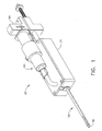
- FIGURE 1 presents a perspective view of one version of a device for severing internal tissues and removing the severed tissues
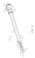
- FIGURE 2 presents a perspective view of the probe portion of the device illustrated in FIG. 1;
- FIGURE 3 presents an exploded perspective view of the probe of FIG. 2 and associated cutter
- FIGURE 4 presents a perspective cross-sectional view of the probe illustrated in FIG. 2 taken along line 4A-4A;
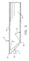
- FIGURE 5 presents a longitudinal cross-sectional view of the distal portion of the cutter illustrated in FIG. 3;
- FIGURE 6 presents a perspective view of the distal portion of the cutter illustrated in FIG. 3;
- FIGURE 7 presents a perspective view of the distal portion of the cutter of FIG. 3 with a grinder inserted into the distal tip of the cutter, illustrating an exemplary method of forming the cutting tip;
- FIGURE 8 presents a longitudinal cross-sectional view of the distal portion of the cutter of FIG. 3, shown with a grinder inserted into the cutter, illustrating an exemplary method of forming the cutting tip;
- FIGURE 9 presents a side perspective view of the grinder of FIG. 8;
- FIGURE 10 presents a partial perspective and transverse cross-sectional view of an alternate version of a cutter and an alternate probe shaft
- FIGURE 11 presents a partial perspective and transverse cross-sectional view of an alternate version of a cutter and an alternate probe shaft
- FIGURE 12 presents a partial perspective and transverse cross-sectional view of an alternate version of a cutter and an alternate probe shaft
- FIGURE 13 presents an exploded perspective view of the device shown in FIG. 1;
- FIGURE 14 presents a side longitudinal cross-sectional view of the device of FIG. 1, in a pre-deployment position;
- FIGURE 15 presents a side longitudinal cross-sectional view of the probe as shown in FIG. 14;
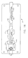
- FIGURE 16 presents a top sectional view of the body portion of the device as shown in FIG. 14;
- FIGURE 17 presents a side longitudinal cross-sectional view of the device of FIG. 1, in an engaged position
- FIGURE 18 presents a side longitudinal cross-sectional view of the probe as shown in FIG. 17;
- FIGURE 19 presents a top sectional view of the body portion of the device as shown in FIG. 17;
- FIGURE 20 presents a side longitudinal cross-sectional view of the device of FIG. 1, in a retracted position
- FIGURE 21 presents a side longitudinal cross-sectional view of the probe as shown in FIG. 20, and after tissue has moved into the receiving aperture;
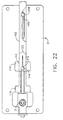
- FIGURE 22 presents a top sectional view of the body portion of the device as shown in FIG. 20;
- FIGURE 23 presents a side longitudinal cross-sectional view of the device of FIG. 1, in a fired position
- FIGURE 24 presents a side longitudinal cross-sectional view of the probe shown in FIG. 23, and after tissue has been severed and captured within the probe;
- FIGURE 25 presents a top sectional view of the body portion of the device as shown in FIG. 23;
- FIGURE 26 presents a side longitudinal cross-sectional view of the device of FIG. 1, during collection of severed tissue
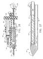
- FIGURE 27 presents a side longitudinal cross-sectional view of the probe as shown in FIG. 26.
- FIGURE 28 is a schematic diagram of a version of a fluid management system that may be used with a device such as the device shown in FIG. 1.
- Versions of a device described and illustrated herein are directed to an efficient system and method for removing tissue in a minimally invasive procedure for biopsy sampling or other purposes.
- versions described herein are directed to a device having a hollow probe with a receiving aperture, and a cutter within the probe having a cutting tip, for efficiently drawing in, cutting and removing tissue in a percutaneous procedure.
- Providing a cutter with an angled and rounded cutting tip, such as described with respect to the exemplary versions herein, may allow for effective cutting of tissue with a predominantly axial motion of the cutter.
- forward or “distal” (and forms thereof) means forward, toward or in the direction of the forward, distal end of the probe portion of the device that is described herein
- rearward or “proximal” (and forms thereof) means rearward or away from the direction of the forward, distal end of the probe portion of the device that is described herein.
- integral refers to two or more identifiable components that are either formed as a single unit or, alternatively, are otherwise joined or attached together such that they move and/or operate substantially as a single unit.
- integrated is not intended to be limited to identifiable components that are continuous or formed from a homogeneous continuum of material.
- identification of separately identifiable components joined together so as to operate substantially integrally is not meant to imply that separately identifiable components are necessarily required, and is not intended to limit the scope of the claims.
- vacuum means pressure within a space that is lower by any amount than atmospheric or ambient pressure, and although not exclusive of a condition of absolute vacuum defined by a complete absence within a space of air, fluid or other matter, the term as used herein is not meant to require or be limited to such a condition.
- FIG. 1 illustrates one example of a device for severing internal tissues and removing the severed tissues.
- Device 20 includes a probe 24, having a distal end and a proximal end, where the proximal end is affixed by any suitable mechanism to a body 21.
- Body 21 may be shaped as shown, or alternatively may be shaped to be aesthetically attractive and/or to form a handle or other conveniently grasped shape, or may have other features, for example, for mounting within or to suitable insertion-guiding, holding and/or steadying or immobilizing devices or fixtures. Versions of the probe 24 and body 21 will be discussed in greater detail herein.
- device 20 includes a probe 24 having a probe shaft 26 having a proximal end and a distal end.
- the probe shaft 26 has receiving aperture 27 through the outer wall 39, which may be positioned near the distal end of the probe 24 as shown.
- the receiving aperture 27 has an oval shape, but the receiving aperture may have any shape suitable to permit effective vacuum aspiration of tissue as will be further described herein.
- the distal portion, or the entire perimeter, of the receiving aperture 27 may be bounded by a beveled or sharpened edge at outer wall 39. Such a beveled or sharpened edge may be included and/or situated to cooperate in scissors-fashion with an internal cutter (to be described below) to facilitate the severing of tissue.
- probe 24 further includes cutter lumen 28 extending axially through the probe 24, configured to house and permit axial movement of a cutter 33 therethrough.
- Cutter lumen 28 may be formed in part by the outer wall 39 of the probe shaft 26, and in part by an inner wall 40 positioned within the probe 24.
- probe 24 includes vacuum lumen 29 through probe shaft 26.
- Inner wall 40 is provided with one or more vacuum ports 30.
- Vacuum ports 30 may include, for example, one or a plurality of holes suitably sized and positioned to allow the passage of air or other fluid therethrough. Vacuum ports 30 may be positioned such that vacuum may be transmitted through vacuum lumen 29, through vacuum ports 30, and into cutter lumen 28.
- vacuum lumen 29 is in fluid communication with a vacuum source port 31, where vacuum source port 31 may be connected to any suitable vacuum source including, for example, vacuum assembly 60 (shown in FIG. 14).
- probe 24 terminates with probe tip 32, which is suitably shaped and suitably sharp so as to enable insertion of probe 24 into tissue and toward a target tissue mass without the necessity of a prior incision to establish a path for the probe to the target tissue mass.
- probe tip 32 may have any suitable piercing and/or cutting shape effective for piercing tissue to create a passage for the probe through tissue, and toward a target tissue mass.
- cutter 33 is formed from hollow tube stock, which forms tissue lumen 34 (see FIG. 5). Cutter 33 may move longitudinally distally and proximally within cutter lumen 28 such that its cutting tip 35 may advance forwardly past receiving aperture 27, thereby closing receiving aperture 27, or retract rearwardly, thereby opening receiving aperture 27.
- cutter 33 is provided with a cutting tip 35 at its distal end.
- cutting tip 35 has a cutting edge 37.
- the angle ⁇ is about 45° in the exemplary version depicted.
- the cutting tip may be formed in other versions wherein the angle ⁇ (formed by a line connecting the most distal extent of cutting edge 37 and the most proximal extent of receding edge 38, and a line perpendicular to the longitudinal axis of the cutter as illustrated in FIG.
- Providing a beveled or angled cutting tip 35 as shown in the illustrated versions results in a curved cutting edge 37 that has a distal-most point, and curves rearwardly on either side of the distal-most point.
- rotating grinder 36 has a semi-ellipsoid shape 42 at its distal end and a diameter that is larger than the diameter of the tube forming cutter 33.
- the grinder may have a hemispherical, hemispheroid, circular semi-paraboloid or other substantially convex distal end shape 42, at least at that portion of its surface (grinding surface) where it will contact and grind cutting edge 37 of cutter 33. Utilizing a grinder having a convex shaped grinding surface to form and sharpen cutting edge 37 provides for a cutting edge 37 having a concave grind, providing a thin and very sharp cutting edge.
- the grinding surface of the grinder used may have a conical or cylindrical shape, if a cutting edge having a concave grind is not desired or deemed necessary.
- sharpening angle ⁇ is about 14°.
- sharpening angle ⁇ of cutting edge 37 may be from about 10° to about 14°, from about 10° to about 15°, from about 10° to about 20°, or from about 10° to about 25°, or alternatively, about 10°, about 11°, about 12°, about 13°, about 14° or about 15°.
- sharpening angle ⁇ may be adjusted by adjusting the angle ⁇ at which the grinder is brought into contact with the distal end of cutter 33. It will be appreciated also that the sharpening angle of the cutting edge can be affected by the diameter of the grinder and the particular shape and/or angle of the grinding surface.
- the sharpening angle and extent of concavity of grind for cutting edge 37 may be adjusted to strike a desired balance between edge thinness and sharpness and tissue cutting effectiveness, and lateral edge strength and edge durability, as may be suitable for the use to which the device may be put.
- the contemplated use for the exemplary versions illustrated herein is taking multiple breast tissue biopsy samples during a single probe insertion, but is not necessarily limited to that application.
- shaping and sharpening of cutting edge 37 of cutter 33 may be of particular concern when a predominantly translational (e.g., substantially non-rotating) cutting stroke is provided by the associated device.
- a thin, very sharp edge may be more desirable for cutting certain types of soft tissue or organ tissue, which might in some circumstances be elastic and evasive to substantially translational advancement of a cutting edge through a protruding portion thereof.
- cutter 33 is used in conjunction with a probe 24 with a receiving aperture 27 defined in part by a sharpened edge to cooperate in scissors-fashion with cutting edge 37, a very thin, extremely sharp cutting edge 37 may in certain circumstances be deemed of lesser importance, or may be deemed undesirable, if more lateral edge strength is deemed desirable.
- receding edge 38 in the exemplary version shown in the figures may be of lesser concern, because for the substantially translating cutter motion provided in the exemplary examples described herein, receding edge 38 may not be substantially involved in cutting tissue.
- a grinder having an ellipsoid, paraboloid, spherical or other convex-shaped grinding surface the grinder of larger diameter than that of the outer diameter of the tube stock from which cutter 33 is formed, may be brought into contact with the tube stock wherein, with reference to FIG. 8, axes 4A and 6A are collinear and angle ⁇ is zero, so as to form no distinguishably leading or receding edges on cutter 33. Rather, with reference to FIG.
- angle ⁇ may be zero and the entire circumference of the tube end may be given a uniform and squared-off cutting edge having a concave grind, such that the resulting cutter might be rotated during a cutting stroke to enhance tissue cutting effectiveness via slicing action, or alternatively, if the device provides only substantially translational cutting motion during actuation, to allow for rotation of a fresh cutting edge into a position proximate to the receiving aperture of the probe during the procedure, in a suitably configured device.
- cutter 33 is contemplated as formed from, by way of example, stainless steel.
- the cutter may be AISI 17-7 PH or type 631 (UNS 17700) stainless steel, condition CH900, suitably hardened to hold a cutting edge.
- Other stainless steels may be suitable, including but not limited to, for example, type 304, type 316 or type 420 stainless steel or other martensitic stainless steel.
- a suitable cutter also may be formed from titanium and/or another metal or metal alloy, including a non-ferrous metal or alloy, which might be selected, for example, so as to be either invisible, or to cause minimal or no distorting effects, when used in conjunction with imaging and guiding techniques and equipment, such as a plastic or a ceramic material, or any other suitable material, including a combination of materials, that provides for shaping and sharpening of an edge of substantial razor-sharpness and sufficient strength and durability for the application contemplated.
- a suitable cutter also may be formed from titanium and/or another metal or metal alloy, including a non-ferrous metal or alloy, which might be selected, for example, so as to be either invisible, or to cause minimal or no distorting effects, when used in conjunction with imaging and guiding techniques and equipment, such as a plastic or a ceramic material, or any other suitable material, including a combination of materials, that provides for shaping and sharpening of an edge of substantial razor-sharpness and sufficient strength and durability for the application contemplated.
- cutter 33 may be formed, for example, from tube stock having, for example, an inner diameter of about 0.085" and an outer diameter of about 0.1025"; or an inner diameter of about 0.063" and an outer diameter of about 0.072", or any other suitable combination of inner and outer diameters.
- an angled cutting tip 35 and a cutting edge 37 having a concave grind may be formed by a rotating grinder 36 having a semi-ellipsoid end shape 42 and a diameter of about 0.1128", semi-minor axis for the ellipsoid end shape 42 of about 0.0564", and a semi-major axis for the ellipsoid end shape 42 of about 0.1350".
- the grinder 36 may be applied to form and sharpen cutter 33 at an angle ⁇ (see FIG. 8) of about 10 degrees, where the forwardmost extent of the cutting edge 37 terminates where the full diameter of the grinder 36 begins, marking the intersection of the semi-minor axis of the semi-ellipsoid end shape 42.
- an angled cutting tip 35 and a cutting edge 37 having a concave grind may be formed by a rotating grinder 36 having a semi-ellipsoid end shape 42 and a diameter of about 0.080", semi-minor axis for the ellipsoid end shape 42 of about 0.040", and a semi-major axis for the ellipsoid shape 42 of about 0.094".
- the grinder 36 may be applied to form and sharpen cutter 33 at an angle ⁇ (see FIG. 8) of about 10 degrees, where the forwardmost extent of the cutting edge 37 terminates where the full diameter of the grinder 36 begins, marking the intersection of the semi-minor axis of the semi-ellipsoid end shape 42.
- the grinder 36 may be made of, or tipped or coated with, any suitable fine grinding material, including but not limited to carbide or ceramic material.
- the grinder may be run at relatively high rotational speeds suitable for producing surgically sharp cutting edges on the selected material, and the grinder and/or cutter tube stock may be cooled using suitable methods during grinding as may be desired to prevent undesirable heating of the cutter tube stock during cutting edge formation and sharpening.
- cutters of other dimensions and materials having angled cutting tips and cutting edges with concave grinds may be produced using the techniques described above.
- the exemplary version of the probe 24 and cutter 33 combination may be used as follows. Following identification of a target tissue mass within a patient, such as a suspected mass within breast tissue, the user may, using suitable immobilization equipment and suitable imaging and/or guidance techniques and equipment, insert probe 24 into and through the skin and tissue, until receiving aperture 27 is within or adjacent to the suspected tissue mass. During insertion, cutter 33 may be held in a forward position so that receiving aperture 27 is closed. When receiving aperture 27 is in the desired location, using a suitable actuating device and/or other equipment associated with the probe, the user may cause cutter 33 to retract proximally so as to open receiving aperture 27 and place cutter 33 into a position ready for cutting.
- the user may cause (manually or by operating any suitable associated device or equipment) a vacuum to be applied via, for example, vacuum source port 31.
- This vacuum can be transmitted to cutter lumen 28 via vacuum lumen 29 and vacuum ports 30, or any other suitable porting or ducting structures or passages, which will cause tissue to be drawn into cutter lumen 28 through receiving aperture 27.
- cutter 33 can be advanced forwardly, in substantially translational motion, so that its cutting edge 37 will contact and sever the tissue drawn into the cutter lumen. As cutter 33 advances, the tissue severed by cutting edge 37 is captured within tissue lumen 34 in cutter 33.
- the distal portion of the edge of receiving aperture 27 may be sharpened so as to cooperate in scissors-fashion with cutter 33 as it advances, to facilitate a final separation or snipping of the tissue being severed during the cutting stroke.
- the severed tissue may then be collected from the tissue lumen 34 by any suitable mechanism. It will be appreciated that a variety of devices and mechanisms may be designed and manufactured to be associated with probe 24 and cutter 33 to effectuate the steps described above.
- a cutter may be formed from a semi-circular, elliptical or other shaped hollow member, as an alterative to a circular tube.
- a cutter might be formed from a member of a minimal size necessary and sufficient to support and drive a cutting edge, for example, a longitudinal member having an open semi-circular or semi-elliptical transverse cross section. Reducing the size of a cutter will permit reduction in size of an associated probe, which will reduce patient discomfort and tissue trauma caused by a procedure.
- a reduction in size of a cutter and probe combination results in a reduction in the amount of tissue that may be removed in a single cutting stroke, which may be undesirable, for example, if a more substantial tissue sample from a single cutting stroke is desired, or if the combination is to be used not only for tissue sampling purposes but also for therapeutic tissue excision purposes.
- an exemplary alternative version of a probe 124 (shown in perspective cross section, without a distal end or receiving aperture) is depicted including an arched or semi-circular cutter 133.
- the probe shaft 126 is circular or elliptical in cross section and is divided by an inner wall 140 into a cutter lumen 128 and a vacuum lumen 129.
- the vacuum lumen 129 may be used to transmit vacuum from a vacuum source (not shown) to a receiving aperture (not shown) for example, in the manner described for the alternative version above.
- the cutter lumen 128 may be, for example, semi-circular in transverse cross section or any other suitable transverse cross sectional shape that houses and provides for the longitudinal movement of a matching cutter 133.
- the inner wall 140 at least partially defining the cutter lumen 128 may be provided with vacuum ports (not shown) as described above for the alternate versions herein.
- Cutter 133 may be provided with cutting tip 135 having a cutting edge 137.
- Cutting tip 135 may be formed by a grinder, such as a grinder 36 (FIG. 9), as discussed above.
- a grinder such as a grinder 36 (FIG. 9)
- Providing, as in the example shown in FIG. 10, a semi-circular transverse cross sectional shape for cutter 133 may allow for reduction of the overall cross-sectional size of the probe 124 thereby reducing the discomfort to the patient and trauma to the tissue caused by a procedure in which the probe is used.
- FIGS. 11-12 additional alternative versions of a probe 224 are depicted, including a cutter 233 having a semicircular, semi-elliptical or arched transverse cross sectional shape.
- the probe shaft 226 is circular or elliptical in transverse cross-sectional shape and the cutter 233 is correspondingly semi-circular or semi-elliptical in cross-sectional shape and is adapted to fit and move axially within the single lumen 229.
- the cutter 233 may be associated with a structure integral thereto, or integral with the probe outer wall 239, such as a track or guide (not shown), to cause cutter 233 to be held and to move axially in adjacent fitting contact to the outer wall 339 as shown.
- vacuum may be applied and transmitted by lumen 229 or by a lumen within a hollow shaft or other structure (not shown) within or about probe 224 to a receiving aperture (not shown) in probe 224 by a suitable configuration and sealing arrangement within an instrument body associated with probe 224.
- a cutting edge such as cutting edge 37, 137, 237
- a grinder such as discussed above, so as to be suitable and effective in severing tissue in a substantially translational cutting stroke.
- a grinder having a convex grinding surface is used to shape or sharpen cutting edge 37, 137, 237, a cutting edge having a concave grind can be produced that is effective for cutting tissue in a substantially translational stroke of the cutter.
- versions of a device such as device 20 may be operably configured to provide for severing and collecting multiple tissue samples and/or excising tissue, with a single insertion of a probe 24.
- a device such as device 20 may be operably configured to be operated and used without an external vacuum or power source.
- a substantially non-rotational cutting mechanism that may be configured to provide the user with an efficient, simple, and versatile tissue removal instrument for performing a variety of minimally invasive internal tissue removal procedures.
- Device 20 includes probe 24 affixed within or to body 21, vacuum assembly 60 held by body 21, cutter driver mechanism 100 held by body 21, and actuator 96.
- vacuum assembly 60 includes a syringe 62 having syringe body 64 and an actuating member such as plunger 66 having plunger tip 67, for creating a vacuum.
- the size and/or proportions of syringe 62 may be selected such that approximately 5 cc of space is created or displaced therein, respectively, during retraction or advancement, respectively, of plunger 66 as will be described further below. It will be appreciated that a syringe (as that term may be typically understood, such as, for example, a hypodermic syringe) is suitable but not necessary.
- any suitable aspirator, cylindrical or otherwise, or other mechanism that creates vacuum upon the movement of an actuating member thereof, may be utilized.
- Nozzle 76 of syringe 62 is connected in a substantially fluid-tight manner to vacuum source port 31 of probe 24, via vacuum tube 70 or any other suitable conduit structure.
- Syringe body 64 may be affixed to body 21 via a holder 82.
- syringe 62 or other suitable aspirator can constitute a vacuum source for the device.
- cutter 33 rides longitudinally within probe 24.
- Cutter 33 extends from its distal end within probe 24, proximally through body 21, terminating with an open proximal portion that may slide longitudinally within actuator 96 as may be seen in FIG. 14.
- Spring collar 116 is affixed about cutter 33 so as move integrally therewith and limit the axial movement thereof.
- firing spring 118 is substantially coaxial with cutter 33 and is held in compression against spring collar 116 at its distal end and against rear block 122 at its proximal end.
- Rear block 122 is affixed within body 21.
- spring collar 116 rests against a forward stop structure, or alternatively, probe boss 50, within body 21 under urging of firing spring 118.
- Spring collar 116 has projecting therefrom an integral firing pin 114.
- firing pin 114 moves longitudinally within firing pin track 115 integral with body 21.
- proximal end of plunger 66 of syringe 62 is integrally affixed to or within actuator 96 by any suitable mechanism, such as but not limited to mating/fitting geometry or set screws.
- proximal and distal motion of actuator 96 will effect substantially corresponding, parallel and coextensive proximal and distal motion of plunger 66, relative to body 21.
- proximal portion of retraction member 102 integrally affixed to or within actuator 96.
- Retraction member 102 rides longitudinally within retraction track 103 incorporated into body 21, and also moves substantially correspondingly, in parallel and coextensively in proximal and distal directions along with plunger 66, with movement of actuator 96.
- Retraction member 102 has integral limiting pin 108 extending downwardly therefrom and into limiting track 110 within body 21. As retraction member 108 is moved rearwardly or forwardly relative to body 21, its rearward and forward motion is checked by interaction of limiting pin 108 with limiting track 110.
- retraction member 102 has at its distal end a nock 112 formed by two flexible extensions 113.
- Nock 112 is adapted to snapably engage and disengage firing pin 114 of spring collar 116, enabled by the outward flexing of the flexible extensions 113 as may be appreciated from FIG. 13.
- retraction member 102 rides longitudinally within retraction track 103.
- the width and sides of retraction track 103 are adapted so as to snugly fit about retraction member 102 or vice versa, and thereby prevent outward flexing of the flexible extensions 113 forming nock 112.
- retraction track 103 includes engagement cavity 170 and disengagement cavity 171.
- nock 112 of retraction member 102 When nock 112 of retraction member 102 is moved to either engagement cavity 170 or disengagement cavity 171 via distal or proximal longitudinal movement of retraction member 102 within retraction track 103, the flexible extensions 113 of nock 112 may flex outwardly laterally, which will permit engagement or disengagement of nock 112 with firing pin 114, as will be described below.
- device 20 also may include a removable sample collection assembly inserted into the open proximal end of, and residing within, cutter 33.
- Sample collection assembly 130 may include collection tube 134 and ejector rod 144, both of which are coaxial with cutter 33 when inserted therein.
- Collection tube 134 is open at both ends, and the proximal end has collection tube knob 136 integrally affixed thereto.
- Collection tube 134 may be formed of a suitable plastic such as polyethylene or other suitable material, and have a wall thickness of about 0.007" to 0.011"; it will be appreciated that a thinner collection tube wall will ease movement past, and collection of, tissue samples within the cutter 33 as will be described below, but that a collection tube wall that is too thin may lack suitable strength and stiffness.
- Ejector rod 144 has ejector rod knob 146 integrally affixed at or near the proximal end thereof, and when ejector rod 144 is fully inserted into collection tube 134, ejector rod knob 146 rests against collection tube knob 136, and may rest within a recess in collection tube knob 136 as shown.
- Return spring 138 is situated on collection tube 134 distally adjacent to collection tube knob 136.
- collection tube 134 is of a length that is substantially equal to or greater than the length of cutter 33, such that by axial/longitudinal depression of collection tube knob 136 by the user in a distal direction, and resulting compression of return spring 138 against actuator 96, the distal end of collection tube 134 may be brought substantially proximate to the distal end of cutter 33.
- Ejector rod 144 is preferably of a length that is substantially equal to the length of collection tube 134 when fully inserted therein.
- ejector rod 144 is of a diameter such that it fits sufficiently snugly within the inside diameter of collection tube 134, such that vacuum applied by vacuum assembly 60 and transmitted into cutter lumen 28 will not draw ejector rod 144 in a forward direction within collection tube 134, rather than draw tissue into receiving aperture 27.
- the fit must be loose enough so as to permit ejector rod 144 to slide rearwardly within collection tube 134 when urged by the contact and pressure of tissue and/or fluid entering the distal end of collection tube 134, as it is advanced by the user to collect severed tissue as will be described further below.
- Collection tube 134 is of a diameter such that it fits sufficiently snugly within the inside diameter of cutter 33, such that vacuum applied by vacuum assembly 60 and transmitted into cutter lumen 28 will not draw collection tube 134 together with ejector rod 144 in a forward direction within collection tube 134, rather than draw tissue into receiving aperture 27. At the same time, collection tube 134 must not fit within cutter 33 so snugly as to prevent movement therewithin at the urging of the user as will be described below.
- FIGS. 14-16 depict the exemplary version of the device in a predeployment position.
- Cutter 33 is in its forwardmost position under urging of firing spring 118 acting against spring collar 116, and thus receiving aperture 27 of probe 24 is closed by cutter 33.
- Nock 112 of retraction member 102 is not engaged with firing pin 114, but is adjacent thereto (see FIG. 16). It can be seen in FIG. 14 that sufficient clearance exists between the tip 67 of plunger 66 and the inside distal limit of syringe body 64 to allow actuator 96 to be moved forward a distance sufficient to cause engagement of nock 112 of retraction member 102 with firing pin 114. It also can be seen in FIG.
- probe 24 may be inserted into tissue, toward a target tissue mass.
- FIGS. 17-19 depict the exemplary version of the device after the retraction member 102 has been engaged with the cutter 33 via engagement of nock 112 about firing pin 114.
- the user may push or otherwise effect movement of actuator 96 in a forward direction relative to body 21.
- retraction member 102 is integral with actuator 96, forward movement of actuator 96 relative to body 21 effects corresponding forward movement of retraction member 102, and nock 112 is urged against firing pin 114.
- Advanced forwardly into engagement cavity 170, the flexible extensions 113 forming nock 112 are permitted to flex outwardly laterally within the clearance provided by engagement cavity 170, allowing nock 112 to open and snap onto and about firing pin 114, thereby grasping it.
- FIGS. 20-22 depict the exemplary version of the device after the user has caused actuator 96 to be retracted rearwardly, after tissue has been drawn into the receiving aperture 27 of probe 24, and just before firing of the cutter 33 as will be described below.
- the user may pull or otherwise effect movement of actuator 96 in a rearward direction relative to body 21.
- retraction member 102 and plunger 66 are integrally affixed to actuator 96, and so rearward movement of actuator 96 relative to body 21 effects corresponding rearward movement of retraction member 102 and plunger 66.
- Rearward movement of retraction member 102 effects reward movement of cutter 33 within probe 24, via engagement and pulling of nock 119 on firing pin 114.
- FIGS. 23-25 depict the exemplary version of the device after release of the firing pin 114 and firing of the cutter 33 to sever and capture tissue within the probe 24.
- the user may further pull or otherwise effect further rearward movement of actuator 96 relative to body 21, to move retraction member 102 the additional distance from the position shown in FIG. 22 to the position shown in FIG. 25.
- This moves flexible extensions 113 forming nock 119 past the distal edges of disengagement cavity 171, thereby allowing flexible extensions 113 to flex outwardly laterally to open nock 112 and release firing pin 114 under urging of firing spring 118 acting on spring collar 116.
- Urging of firing spring 118 moves cutter 33 and cutting tip 35 thereof forward past receiving aperture 27, effectively severing tissue drawn therethrough, and capturing the severed tissue within tissue lumen 34 of cutter 33 as depicted in FIG. 24.
- Rearward motion of retraction member 102 (and correspondingly, rearward motion of actuator 96) is limited to a rearwardmost extent by interaction of limiting pin 108 with track 110.
- the exemplary version of the device depicted provides for coordinated rearward movement of cutter 33 to a position ready for a cutting stroke, opening of receiving aperture 27 of probe 24, development of vacuum to draw tissues into receiving aperture 27, and compressing of firing spring 118, all effected by rearward movement of actuator 96.
- the last incremental rearward movement of actuator 96 effects release of firing pin 114 as nock 112 of retraction member 102 moves into disengagement cavity 171, and the resulting firing of cutter 33 in a forward direction under urging of firing spring 118 acting against spring collar 116.
- plunger 66 of syringe 62 continues to be pulled rearwardly toward its rearwardmost position in order to maintain vacuum within the system during the cutting stroke.
- FIGS. 26-27 depict the exemplary version of the device as the collection tube 134 is being advanced forwardly to capture and collect a severed tissue sample.
- the user may advance collection tube knob 136 forward relative to body 21, thereby advancing collection tube 134 forward within cutter 33 so that it captures the severed tissue sample therewithin, as shown in progress in FIG. 27.
- the severed tissue sample enters the distal end thereof, and either the severed tissue or a small quantity of air and/or fluid trapped between the proximal portion of the severed tissue and the distal end of ejector rod 144 will contact and urge ejector rod 144 rearwardly relative to collection tube 134 to make room for the tissue sample within the collection tube 134.
- collection tube knob 136 After the tissue sample is captured within collection tube 134, the user may release collection tube knob 136, and under urging of return spring 138, collection tube knob 136 and correspondingly, collection tube 134 holding the severed tissue, will return to a predetermined position, with the distal end of collection tube 134 proximal to receiving aperture 27. Following that, the user may, by effecting movement of actuator 96 forward with respect to body 21, reset the device to the position shown in FIGS. 17-19 in preparation for drawing in and severing another tissue sample by repeating the steps described above.
- the user may entirely withdraw collection tube 134 from the device by pulling knob 136 rearwardly, and eject severed tissue sample(s) contained therein by advancing ejector rod 144 forwardly within collection tube 134, pushing the sample(s) out the distal end of collection tube 134.
- ejector rod 144 will move rearwardly relative to collection tube 134 as each sample moves into the distal end of collection tube 134, and the position of ejector rod 144 and/or ejector rod knob 146 with respect to collection tube knob 136 can thereby serve as an indicator of the amount of severed tissue and/or number of tissue samples contained within collection tube 134. Accordingly, ejector rod 144 may be marked with one or more visible indicators (not shown) to more effectively provide this information to the user.
- the vacuum within the device created by the rearward movement of plunger 66 within syringe 62 can possibly cause air or other fluids to be drawn into the device via system leaks, or by drawing body fluids into receiving aperture 27 in addition to tissue, and such fluids can enter the vacuum system via vacuum apertures 30 and vacuum lumen 29 (see FIG. 4).
- FIG. 28 schematically depicts one version of a system that can serve such a function.
- the exemplary fluid management system 150 includes a three-way junction 152 in the line of fluid communication between syringe 62 and vacuum lumen 29 of probe 24.
- One leg of three-way junction 152 may be vented to or placed in fluid communication by suitable tubing or other conduit mechanism with a receptacle 158 suitably configured to receive fluids vented, drained or expelled from the device. If a closed system is desired, fluids may be vented or expelled into an expandable bladder 160 via sealed connections, for purposes of, among others, avoiding an undesirable or counterproductive creation of back pressure within the receptacle 158.
- a first one-way check valve 154 lies in line between vacuum lumen 29 and three-way junction 152, such that it permits fluid flow away from but not toward vacuum lumen 29.
- a second one-way check valve 156 lies in line between receptacle 158 and three-way junction 152, such that it permits fluid flow away from but not toward three-way junction 152. From FIG. 28, it will be appreciated that this arrangement will allow fluid flow from vacuum lumen 29 of probe 24 and toward and possibly into syringe 62, but not vice versa, and this arrangement will allow fluid flow from syringe 62 and toward and into receptacle 158, but not vice versa. Thus, when syringe 62 creates a vacuum, it will draw fluid from the probe 24, but not from the receptacle 158, because such flow is prevented by second one-way check valve 156.
- One-way valves 154, 156 and three-way junction 152 may be arranged and positioned within, on or about the device with suitable fluid conduit or passage structures such that a minimum quantity of unwanted fluid may remain in the system following expulsion by, for example, distal movement of plunger 66 in syringe 62.
- fluid management system 150 may include, for example, an exit tube coupled with one leg of junction 152 for the removal of fluid, which may, but need not necessarily, vent or drain into a receptacle.
- Receptacle 158 may, for example, comprise a vessel or container of any description, or an expandable bladder such as a balloon that simply expands as fluid is driven thereinto.
- Expandable bladder 160 may be, for example, any suitable bag, balloon, pouch, or flexible container.
- any suitable mechanism that creates a vacuum such as a syringe 62, other aspirator, or outboard vacuum source, may be used to supply vacuum to draw tissues into the probe 24 in accordance with versions described herein. It will be appreciated that various configurations, orientations and locations of the vacuum assembly 60 may be provided in accordance with the versions described herein. It will be apparent that the vacuum supplied by movement of an actuating member of an aspirator such as plunger 66, that draws tissue into receiving aperture 27 in the exemplary versions depicted, is supplied during or after opening of the receiving aperture 27 and before or during a cutting stroke.
- vacuum may be supplied effectively while a receiving aperture is open, and effectively prior to and during at least a portion of the time a cutting edge moves across such receiving aperture in a cutting stroke, so as to provide that tissue is drawn into and present within a probe so that it can be severed in a cutting stroke. It will be understood, however, that simultaneous movement of a cutter and a plunger prior to a cutting stroke may be desirable in some circumstances for purposes of configuration of the driving mechanism(s) or other structures, but is not necessarily required to effect the proper timing of creation of vacuum within the probe.
- a plunger or other aspirator actuating member and a cutter may be decoupled and effected by separate mechanisms to provide for the creation of vacuum that is suitably timed with respect to a cutting stroke to ensure that tissue is drawn into a probe and situated in a position in which it can be effectively severed and removed by an associated device.
- the exemplary version described and depicted herein involves a trip mechanism (the interacting combination of nock 112 on retraction member 102, and disengagement cavity 171 in retraction track 103) for alternately restraining, and then releasing, a member upon which a spring exerts force, to effect driving of components such as cutter 33.
- a trip mechanism the interacting combination of nock 112 on retraction member 102, and disengagement cavity 171 in retraction track 103 for alternately restraining, and then releasing, a member upon which a spring exerts force, to effect driving of components such as cutter 33.
- suitable trip mechanisms to alternately restrain and then release such devices may take a variety of suitable forms in addition to the example described and depicted herein.
- any suitable cutter driving mechanism such as a rotational or non-rotational driving mechanism, may be used in accordance with versions described herein.
- the driving force to effect forward motion of the cutter 33 is supplied by a compressed spring, firing spring 118.
- a compressed spring firing spring 118.
- such driving force can be supplied by any other suitable driving mechanism, such as but not limited to other types of springs in compression, tension, flexion or torsion, by other longitudinally motive devices such as gas or fluid cylinders or levers and/or gear-driven devices operably configured to store and release potential energy to supply longitudinal motive forces, or alternatively, to supply longitudinal motive forces by converting and/or transferring forces developed or supplied through other mechanisms.
- suitable longitudinal forces might by supplied by hand-operated or motor-driven lever and/or gear mechanisms, used in conjunction with one or more spring devices, or not.
- a component such as actuator 96 or other component to transfer force and movement to charge a cutter driving mechanism may be manually actuated by a user or may, for example, be automated and/or part of an automatic system.
- tissue samples may be removed immediately, or retained within an onboard receptacle other than a collection tube.
Abstract
Description
- Devices utilizing hollow probe aspiration are useful for removing and/or obtaining samples of tissue in minimally invasive percutaneous procedures, for biopsy or other purposes, such as therapeutic tissue removal purposes.
- It may be desirable to provide additional and alternative designs for an instrument including a hollow probe that allows for effective and efficient sample cutting and removal, minimal trauma to tissue and to the patient in the tissue removal procedure, and of relatively simple design, manufacture and use.
- A variety of such devices have been developed and used, but to the best of the inventors' knowledge, no one prior to the inventors has created or used the invention described in the appended claims.
- While the specification concludes with claims that particularly point out and distinctly claim the invention, it is believed the present invention will be better understood from the following description taken in conjunction with the accompanying drawings, in which like reference numerals identify the same elements. The drawings and detailed description which follow are intended to be merely illustrative and are not intended to limit the scope of the invention as set forth in the appended claims.
- FIGURE 1 presents a perspective view of one version of a device for severing internal tissues and removing the severed tissues;
- FIGURE 2 presents a perspective view of the probe portion of the device illustrated in FIG. 1;
- FIGURE 3 presents an exploded perspective view of the probe of FIG. 2 and associated cutter;
- FIGURE 4 presents a perspective cross-sectional view of the probe illustrated in FIG. 2 taken along
line 4A-4A; - FIGURE 5 presents a longitudinal cross-sectional view of the distal portion of the cutter illustrated in FIG. 3;
- FIGURE 6 presents a perspective view of the distal portion of the cutter illustrated in FIG. 3;
- FIGURE 7 presents a perspective view of the distal portion of the cutter of FIG. 3 with a grinder inserted into the distal tip of the cutter, illustrating an exemplary method of forming the cutting tip;
- FIGURE 8 presents a longitudinal cross-sectional view of the distal portion of the cutter of FIG. 3, shown with a grinder inserted into the cutter, illustrating an exemplary method of forming the cutting tip;
- FIGURE 9 presents a side perspective view of the grinder of FIG. 8;
- FIGURE 10 presents a partial perspective and transverse cross-sectional view of an alternate version of a cutter and an alternate probe shaft;
- FIGURE 11 presents a partial perspective and transverse cross-sectional view of an alternate version of a cutter and an alternate probe shaft;
- FIGURE 12 presents a partial perspective and transverse cross-sectional view of an alternate version of a cutter and an alternate probe shaft;
- FIGURE 13 presents an exploded perspective view of the device shown in FIG. 1;
- FIGURE 14 presents a side longitudinal cross-sectional view of the device of FIG. 1, in a pre-deployment position;
- FIGURE 15 presents a side longitudinal cross-sectional view of the probe as shown in FIG. 14;
- FIGURE 16 presents a top sectional view of the body portion of the device as shown in FIG. 14;
- FIGURE 17 presents a side longitudinal cross-sectional view of the device of FIG. 1, in an engaged position;
- FIGURE 18 presents a side longitudinal cross-sectional view of the probe as shown in FIG. 17;
- FIGURE 19 presents a top sectional view of the body portion of the device as shown in FIG. 17;
- FIGURE 20 presents a side longitudinal cross-sectional view of the device of FIG. 1, in a retracted position;
- FIGURE 21 presents a side longitudinal cross-sectional view of the probe as shown in FIG. 20, and after tissue has moved into the receiving aperture;
- FIGURE 22 presents a top sectional view of the body portion of the device as shown in FIG. 20;
- FIGURE 23 presents a side longitudinal cross-sectional view of the device of FIG. 1, in a fired position;
- FIGURE 24 presents a side longitudinal cross-sectional view of the probe shown in FIG. 23, and after tissue has been severed and captured within the probe;
- FIGURE 25 presents a top sectional view of the body portion of the device as shown in FIG. 23;
- FIGURE 26 presents a side longitudinal cross-sectional view of the device of FIG. 1, during collection of severed tissue;
- FIGURE 27 presents a side longitudinal cross-sectional view of the probe as shown in FIG. 26; and
- FIGURE 28 is a schematic diagram of a version of a fluid management system that may be used with a device such as the device shown in FIG. 1.
- Versions of a device described and illustrated herein are directed to an efficient system and method for removing tissue in a minimally invasive procedure for biopsy sampling or other purposes. In particular, versions described herein are directed to a device having a hollow probe with a receiving aperture, and a cutter within the probe having a cutting tip, for efficiently drawing in, cutting and removing tissue in a percutaneous procedure. Providing a cutter with an angled and rounded cutting tip, such as described with respect to the exemplary versions herein, may allow for effective cutting of tissue with a predominantly axial motion of the cutter.
- For purposes of the description contained herein, with respect to components and movement of components described herein, "forward" or "distal" (and forms thereof) means forward, toward or in the direction of the forward, distal end of the probe portion of the device that is described herein, and "rearward" or "proximal" (and forms thereof) means rearward or away from the direction of the forward, distal end of the probe portion of the device that is described herein. However, it should be understood that these uses of these terms are for purposes of reference and orientation with respect to the description and drawings herein, and are not intended to limit the scope of the claims.
- For purposes of the description contained herein, with respect to components described herein, the term "integral" refers to two or more identifiable components that are either formed as a single unit or, alternatively, are otherwise joined or attached together such that they move and/or operate substantially as a single unit. The term "integral" is not intended to be limited to identifiable components that are continuous or formed from a homogeneous continuum of material. However, it should be understood that the identification of separately identifiable components joined together so as to operate substantially integrally is not meant to imply that separately identifiable components are necessarily required, and is not intended to limit the scope of the claims.
- For purposes of the description contained herein, "vacuum" means pressure within a space that is lower by any amount than atmospheric or ambient pressure, and although not exclusive of a condition of absolute vacuum defined by a complete absence within a space of air, fluid or other matter, the term as used herein is not meant to require or be limited to such a condition.
- Turning to the drawings, FIG. 1 illustrates one example of a device for severing internal tissues and removing the severed tissues.
Device 20 includes aprobe 24, having a distal end and a proximal end, where the proximal end is affixed by any suitable mechanism to abody 21.Body 21 may be shaped as shown, or alternatively may be shaped to be aesthetically attractive and/or to form a handle or other conveniently grasped shape, or may have other features, for example, for mounting within or to suitable insertion-guiding, holding and/or steadying or immobilizing devices or fixtures. Versions of theprobe 24 andbody 21 will be discussed in greater detail herein. - Referring now to FIGS. 2-4, in the exemplary version shown,
device 20 includes aprobe 24 having aprobe shaft 26 having a proximal end and a distal end. Theprobe shaft 26 has receivingaperture 27 through theouter wall 39, which may be positioned near the distal end of theprobe 24 as shown. In the version shown, the receivingaperture 27 has an oval shape, but the receiving aperture may have any shape suitable to permit effective vacuum aspiration of tissue as will be further described herein. The distal portion, or the entire perimeter, of thereceiving aperture 27 may be bounded by a beveled or sharpened edge atouter wall 39. Such a beveled or sharpened edge may be included and/or situated to cooperate in scissors-fashion with an internal cutter (to be described below) to facilitate the severing of tissue. - In the exemplary version shown,
probe 24 further includescutter lumen 28 extending axially through theprobe 24, configured to house and permit axial movement of acutter 33 therethrough.Cutter lumen 28 may be formed in part by theouter wall 39 of theprobe shaft 26, and in part by aninner wall 40 positioned within theprobe 24. - Still referring to FIGS. 2-4, in the exemplary version shown,
probe 24 includesvacuum lumen 29 throughprobe shaft 26.Inner wall 40 is provided with one ormore vacuum ports 30.Vacuum ports 30 may include, for example, one or a plurality of holes suitably sized and positioned to allow the passage of air or other fluid therethrough.Vacuum ports 30 may be positioned such that vacuum may be transmitted throughvacuum lumen 29, throughvacuum ports 30, and intocutter lumen 28. In the illustrated version,vacuum lumen 29 is in fluid communication with avacuum source port 31, wherevacuum source port 31 may be connected to any suitable vacuum source including, for example, vacuum assembly 60 (shown in FIG. 14). - In the exemplary version,
probe 24 terminates withprobe tip 32, which is suitably shaped and suitably sharp so as to enable insertion ofprobe 24 into tissue and toward a target tissue mass without the necessity of a prior incision to establish a path for the probe to the target tissue mass. It will be appreciated thatprobe tip 32 may have any suitable piercing and/or cutting shape effective for piercing tissue to create a passage for the probe through tissue, and toward a target tissue mass. - In the exemplary version shown,
cutter 33 is formed from hollow tube stock, which forms tissue lumen 34 (see FIG. 5).Cutter 33 may move longitudinally distally and proximally withincutter lumen 28 such that itscutting tip 35 may advance forwardly past receivingaperture 27, thereby closing receivingaperture 27, or retract rearwardly, thereby opening receivingaperture 27. - In the exemplary version,
cutter 33 is provided with a cuttingtip 35 at its distal end. Referring to FIGS. 5-8, cuttingtip 35 has acutting edge 37. Referring to FIG. 5, the angle Γ is about 45° in the exemplary version depicted. However, the cutting tip may be formed in other versions wherein the angle Γ (formed by a line connecting the most distal extent of cuttingedge 37 and the most proximal extent of recedingedge 38, and a line perpendicular to the longitudinal axis of the cutter as illustrated in FIG. 5), is from about 30° to about 60°, from about 40° to about 60°, from about 45° to about 60°, from about 45° to about 55°, or from about 45° to about 50°, or alternatively, about 50°, about 55° or about 60°. Providing a beveled or angled cuttingtip 35 as shown in the illustrated versions results in acurved cutting edge 37 that has a distal-most point, and curves rearwardly on either side of the distal-most point. - Referring to FIGS. 5-9, it can be seen that the cutting
tip 35, including thecutting edge 37, may be formed and/or sharpened by use of a suitably shaped rotatinggrinder 36. In the exemplary version ofcutter 33 and the exemplary method of forming and/or sharpening illustrated, rotatinggrinder 36 has asemi-ellipsoid shape 42 at its distal end and a diameter that is larger than the diameter of thetube forming cutter 33. Alternatively, the grinder may have a hemispherical, hemispheroid, circular semi-paraboloid or other substantially convexdistal end shape 42, at least at that portion of its surface (grinding surface) where it will contact andgrind cutting edge 37 ofcutter 33. Utilizing a grinder having a convex shaped grinding surface to form and sharpen cuttingedge 37 provides for acutting edge 37 having a concave grind, providing a thin and very sharp cutting edge. - Alternatively, the grinding surface of the grinder used may have a conical or cylindrical shape, if a cutting edge having a concave grind is not desired or deemed necessary.
- Another technique for producing a thin, sharp cutting edge resides in control and manipulation of the sharpening angle Φ for cutting edge 37 (see FIG. 5). In the exemplary version shown, sharpening angle Φ is about 14°. Alternatively, in other versions sharpening angle Φ of cutting
edge 37 may be from about 10° to about 14°, from about 10° to about 15°, from about 10° to about 20°, or from about 10° to about 25°, or alternatively, about 10°, about 11°, about 12°, about 13°, about 14° or about 15°. Referring to the example illustrated in FIGS. 5-8, it can be appreciated that sharpening angle Φ may be adjusted by adjusting the angle θ at which the grinder is brought into contact with the distal end ofcutter 33. It will be appreciated also that the sharpening angle of the cutting edge can be affected by the diameter of the grinder and the particular shape and/or angle of the grinding surface. - The sharpening angle and extent of concavity of grind for cutting
edge 37 may be adjusted to strike a desired balance between edge thinness and sharpness and tissue cutting effectiveness, and lateral edge strength and edge durability, as may be suitable for the use to which the device may be put. The contemplated use for the exemplary versions illustrated herein is taking multiple breast tissue biopsy samples during a single probe insertion, but is not necessarily limited to that application. - It will be appreciated that the shaping and sharpening of cutting
edge 37 ofcutter 33 may be of particular concern when a predominantly translational (e.g., substantially non-rotating) cutting stroke is provided by the associated device. In this circumstance, a thin, very sharp edge may be more desirable for cutting certain types of soft tissue or organ tissue, which might in some circumstances be elastic and evasive to substantially translational advancement of a cutting edge through a protruding portion thereof. - If the
cutter 33 is used in conjunction with aprobe 24 with a receivingaperture 27 defined in part by a sharpened edge to cooperate in scissors-fashion with cuttingedge 37, a very thin, extremelysharp cutting edge 37 may in certain circumstances be deemed of lesser importance, or may be deemed undesirable, if more lateral edge strength is deemed desirable. - The shape and edge sharpness of receding
edge 38 in the exemplary version shown in the figures may be of lesser concern, because for the substantially translating cutter motion provided in the exemplary examples described herein, recedingedge 38 may not be substantially involved in cutting tissue. However, it also will be appreciated that a grinder having an ellipsoid, paraboloid, spherical or other convex-shaped grinding surface, the grinder of larger diameter than that of the outer diameter of the tube stock from whichcutter 33 is formed, may be brought into contact with the tube stock wherein, with reference to FIG. 8, axes 4A and 6A are collinear and angle θ is zero, so as to form no distinguishably leading or receding edges oncutter 33. Rather, with reference to FIG. 5, angle Γ may be zero and the entire circumference of the tube end may be given a uniform and squared-off cutting edge having a concave grind, such that the resulting cutter might be rotated during a cutting stroke to enhance tissue cutting effectiveness via slicing action, or alternatively, if the device provides only substantially translational cutting motion during actuation, to allow for rotation of a fresh cutting edge into a position proximate to the receiving aperture of the probe during the procedure, in a suitably configured device. - The illustrated and described version of
cutter 33 is contemplated as formed from, by way of example, stainless steel. For example, the cutter may be AISI 17-7 PH or type 631 (UNS 17700) stainless steel, condition CH900, suitably hardened to hold a cutting edge. Other stainless steels may be suitable, including but not limited to, for example, type 304, type 316 or type 420 stainless steel or other martensitic stainless steel. However, a suitable cutter also may be formed from titanium and/or another metal or metal alloy, including a non-ferrous metal or alloy, which might be selected, for example, so as to be either invisible, or to cause minimal or no distorting effects, when used in conjunction with imaging and guiding techniques and equipment, such as a plastic or a ceramic material, or any other suitable material, including a combination of materials, that provides for shaping and sharpening of an edge of substantial razor-sharpness and sufficient strength and durability for the application contemplated. - In the exemplary version depicted,
cutter 33 may be formed, for example, from tube stock having, for example, an inner diameter of about 0.085" and an outer diameter of about 0.1025"; or an inner diameter of about 0.063" and an outer diameter of about 0.072", or any other suitable combination of inner and outer diameters. - For example, referring to FIGS. 5-9, for a
cutter 33 having an inner diameter of about 0.085" and an outer diameter of about 0.1025", anangled cutting tip 35 and acutting edge 37 having a concave grind may be formed by a rotatinggrinder 36 having asemi-ellipsoid end shape 42 and a diameter of about 0.1128", semi-minor axis for theellipsoid end shape 42 of about 0.0564", and a semi-major axis for theellipsoid end shape 42 of about 0.1350". Thegrinder 36 may be applied to form and sharpencutter 33 at an angle θ (see FIG. 8) of about 10 degrees, where the forwardmost extent of thecutting edge 37 terminates where the full diameter of thegrinder 36 begins, marking the intersection of the semi-minor axis of thesemi-ellipsoid end shape 42. - By way of further example, referring to FIGS. 5-9, for a
cutter 33 having an inner diameter of about 0.063" and an outer diameter of about 0.072", anangled cutting tip 35 and acutting edge 37 having a concave grind may be formed by a rotatinggrinder 36 having asemi-ellipsoid end shape 42 and a diameter of about 0.080", semi-minor axis for theellipsoid end shape 42 of about 0.040", and a semi-major axis for theellipsoid shape 42 of about 0.094". Thegrinder 36 may be applied to form and sharpencutter 33 at an angle θ (see FIG. 8) of about 10 degrees, where the forwardmost extent of thecutting edge 37 terminates where the full diameter of thegrinder 36 begins, marking the intersection of the semi-minor axis of thesemi-ellipsoid end shape 42. - The
grinder 36 may be made of, or tipped or coated with, any suitable fine grinding material, including but not limited to carbide or ceramic material. The grinder may be run at relatively high rotational speeds suitable for producing surgically sharp cutting edges on the selected material, and the grinder and/or cutter tube stock may be cooled using suitable methods during grinding as may be desired to prevent undesirable heating of the cutter tube stock during cutting edge formation and sharpening. - The foregoing are only examples and it will be appreciated that cutters of other dimensions and materials having angled cutting tips and cutting edges with concave grinds may be produced using the techniques described above.
- Referring back to FIGS. 2-5, the exemplary version of the
probe 24 andcutter 33 combination may be used as follows. Following identification of a target tissue mass within a patient, such as a suspected mass within breast tissue, the user may, using suitable immobilization equipment and suitable imaging and/or guidance techniques and equipment, insertprobe 24 into and through the skin and tissue, until receivingaperture 27 is within or adjacent to the suspected tissue mass. During insertion,cutter 33 may be held in a forward position so that receivingaperture 27 is closed. When receivingaperture 27 is in the desired location, using a suitable actuating device and/or other equipment associated with the probe, the user may causecutter 33 to retract proximally so as to open receivingaperture 27 andplace cutter 33 into a position ready for cutting. Contemporaneously or thereafter the user may cause (manually or by operating any suitable associated device or equipment) a vacuum to be applied via, for example,vacuum source port 31. This vacuum can be transmitted tocutter lumen 28 viavacuum lumen 29 andvacuum ports 30, or any other suitable porting or ducting structures or passages, which will cause tissue to be drawn intocutter lumen 28 through receivingaperture 27. Then,cutter 33 can be advanced forwardly, in substantially translational motion, so that itscutting edge 37 will contact and sever the tissue drawn into the cutter lumen. Ascutter 33 advances, the tissue severed by cuttingedge 37 is captured withintissue lumen 34 incutter 33. As noted above, the distal portion of the edge of receivingaperture 27 may be sharpened so as to cooperate in scissors-fashion withcutter 33 as it advances, to facilitate a final separation or snipping of the tissue being severed during the cutting stroke. The severed tissue may then be collected from thetissue lumen 34 by any suitable mechanism. It will be appreciated that a variety of devices and mechanisms may be designed and manufactured to be associated withprobe 24 andcutter 33 to effectuate the steps described above. - In another version, a cutter may formed from a semi-circular, elliptical or other shaped hollow member, as an alterative to a circular tube. Alternatively, a cutter might be formed from a member of a minimal size necessary and sufficient to support and drive a cutting edge, for example, a longitudinal member having an open semi-circular or semi-elliptical transverse cross section. Reducing the size of a cutter will permit reduction in size of an associated probe, which will reduce patient discomfort and tissue trauma caused by a procedure. It will be appreciated, however, that a reduction in size of a cutter and probe combination results in a reduction in the amount of tissue that may be removed in a single cutting stroke, which may be undesirable, for example, if a more substantial tissue sample from a single cutting stroke is desired, or if the combination is to be used not only for tissue sampling purposes but also for therapeutic tissue excision purposes.
- Referring to FIG. 10, an exemplary alternative version of a probe 124 (shown in perspective cross section, without a distal end or receiving aperture) is depicted including an arched or
semi-circular cutter 133. In the illustrated exemplary version, theprobe shaft 126 is circular or elliptical in cross section and is divided by aninner wall 140 into acutter lumen 128 and a vacuum lumen 129. The vacuum lumen 129 may be used to transmit vacuum from a vacuum source (not shown) to a receiving aperture (not shown) for example, in the manner described for the alternative version above. Thecutter lumen 128 may be, for example, semi-circular in transverse cross section or any other suitable transverse cross sectional shape that houses and provides for the longitudinal movement of amatching cutter 133. Theinner wall 140 at least partially defining thecutter lumen 128 may be provided with vacuum ports (not shown) as described above for the alternate versions herein.Cutter 133 may be provided with cuttingtip 135 having acutting edge 137. Cuttingtip 135 may be formed by a grinder, such as a grinder 36 (FIG. 9), as discussed above. Providing, as in the example shown in FIG. 10, a semi-circular transverse cross sectional shape forcutter 133 may allow for reduction of the overall cross-sectional size of theprobe 124 thereby reducing the discomfort to the patient and trauma to the tissue caused by a procedure in which the probe is used. - Referring to FIGS. 11-12, additional alternative versions of a
probe 224 are depicted, including acutter 233 having a semicircular, semi-elliptical or arched transverse cross sectional shape. In one version, theprobe shaft 226 is circular or elliptical in transverse cross-sectional shape and thecutter 233 is correspondingly semi-circular or semi-elliptical in cross-sectional shape and is adapted to fit and move axially within thesingle lumen 229. Thecutter 233 may be associated with a structure integral thereto, or integral with the probeouter wall 239, such as a track or guide (not shown), to causecutter 233 to be held and to move axially in adjacent fitting contact to the outer wall 339 as shown. In the absence of an inner wall defining separate vacuum and cutter lumens withinprobe 224, vacuum may be applied and transmitted bylumen 229 or by a lumen within a hollow shaft or other structure (not shown) within or aboutprobe 224 to a receiving aperture (not shown) inprobe 224 by a suitable configuration and sealing arrangement within an instrument body associated withprobe 224. - It will be noted, however, that in all alternative versions of
cutter edge edge - Referring back to FIG. 1, versions of a device such as
device 20 may be operably configured to provide for severing and collecting multiple tissue samples and/or excising tissue, with a single insertion of aprobe 24. A device such asdevice 20 may be operably configured to be operated and used without an external vacuum or power source. Provided in versions discussed herein is a substantially non-rotational cutting mechanism that may be configured to provide the user with an efficient, simple, and versatile tissue removal instrument for performing a variety of minimally invasive internal tissue removal procedures. - Referring to FIGS. 1-2 and 13-15, an exemplary version of such a
device 20 is depicted.Device 20 includesprobe 24 affixed within or tobody 21,vacuum assembly 60 held bybody 21,cutter driver mechanism 100 held bybody 21, andactuator 96. - In the exemplary version depicted,
vacuum assembly 60 includes asyringe 62 havingsyringe body 64 and an actuating member such asplunger 66 havingplunger tip 67, for creating a vacuum. The size and/or proportions ofsyringe 62 may be selected such that approximately 5 cc of space is created or displaced therein, respectively, during retraction or advancement, respectively, ofplunger 66 as will be described further below. It will be appreciated that a syringe (as that term may be typically understood, such as, for example, a hypodermic syringe) is suitable but not necessary. Rather, any suitable aspirator, cylindrical or otherwise, or other mechanism that creates vacuum upon the movement of an actuating member thereof, may be utilized.Nozzle 76 ofsyringe 62 is connected in a substantially fluid-tight manner to vacuumsource port 31 ofprobe 24, viavacuum tube 70 or any other suitable conduit structure.Syringe body 64 may be affixed tobody 21 via aholder 82. Thus disposed,syringe 62 or other suitable aspirator can constitute a vacuum source for the device. - As previously described above, in the exemplary versions depicted
cutter 33 rides longitudinally withinprobe 24.Cutter 33 extends from its distal end withinprobe 24, proximally throughbody 21, terminating with an open proximal portion that may slide longitudinally withinactuator 96 as may be seen in FIG. 14.Spring collar 116 is affixed aboutcutter 33 so as move integrally therewith and limit the axial movement thereof. As may be seen in FIG. 14, firingspring 118 is substantially coaxial withcutter 33 and is held in compression againstspring collar 116 at its distal end and againstrear block 122 at its proximal end. Rear block 122 is affixed withinbody 21. Thus, it can be appreciated that firingspring 118 acts to urgecutter 33 forward relative tobody 21, viaspring collar 116. In a pre-deployment position,spring collar 116 rests against a forward stop structure, or alternatively,probe boss 50, withinbody 21 under urging of firingspring 118.Spring collar 116 has projecting therefrom anintegral firing pin 114. Asspring collar 116 moves longitudinally withinbody 21,firing pin 114 moves longitudinally withinfiring pin track 115 integral withbody 21. - In the exemplary version depicted, the proximal end of
plunger 66 ofsyringe 62 is integrally affixed to or withinactuator 96 by any suitable mechanism, such as but not limited to mating/fitting geometry or set screws. Thus, it can be appreciated that proximal and distal motion ofactuator 96 will effect substantially corresponding, parallel and coextensive proximal and distal motion ofplunger 66, relative tobody 21. Also integrally affixed to or withinactuator 96 is the proximal portion ofretraction member 102.Retraction member 102 rides longitudinally withinretraction track 103 incorporated intobody 21, and also moves substantially correspondingly, in parallel and coextensively in proximal and distal directions along withplunger 66, with movement ofactuator 96.Retraction member 102 has integral limitingpin 108 extending downwardly therefrom and into limitingtrack 110 withinbody 21. Asretraction member 108 is moved rearwardly or forwardly relative tobody 21, its rearward and forward motion is checked by interaction of limitingpin 108 with limitingtrack 110. - In the exemplary version depicted,
retraction member 102 has at its distal end anock 112 formed by twoflexible extensions 113.Nock 112 is adapted to snapably engage and disengagefiring pin 114 ofspring collar 116, enabled by the outward flexing of theflexible extensions 113 as may be appreciated from FIG. 13. As noted,retraction member 102 rides longitudinally withinretraction track 103. The width and sides ofretraction track 103 are adapted so as to snugly fit aboutretraction member 102 or vice versa, and thereby prevent outward flexing of theflexible extensions 113 formingnock 112. However,retraction track 103 includesengagement cavity 170 anddisengagement cavity 171. When nock 112 ofretraction member 102 is moved to eitherengagement cavity 170 ordisengagement cavity 171 via distal or proximal longitudinal movement ofretraction member 102 withinretraction track 103, theflexible extensions 113 ofnock 112 may flex outwardly laterally, which will permit engagement or disengagement ofnock 112 withfiring pin 114, as will be described below. - In the exemplary version depicted,
device 20 also may include a removable sample collection assembly inserted into the open proximal end of, and residing within,cutter 33.Sample collection assembly 130 may includecollection tube 134 andejector rod 144, both of which are coaxial withcutter 33 when inserted therein.Collection tube 134 is open at both ends, and the proximal end hascollection tube knob 136 integrally affixed thereto.Collection tube 134 may be formed of a suitable plastic such as polyethylene or other suitable material, and have a wall thickness of about 0.007" to 0.011"; it will be appreciated that a thinner collection tube wall will ease movement past, and collection of, tissue samples within thecutter 33 as will be described below, but that a collection tube wall that is too thin may lack suitable strength and stiffness.Ejector rod 144 hasejector rod knob 146 integrally affixed at or near the proximal end thereof, and whenejector rod 144 is fully inserted intocollection tube 134,ejector rod knob 146 rests againstcollection tube knob 136, and may rest within a recess incollection tube knob 136 as shown.Return spring 138 is situated oncollection tube 134 distally adjacent tocollection tube knob 136. In the exemplary version,collection tube 134 is of a length that is substantially equal to or greater than the length ofcutter 33, such that by axial/longitudinal depression ofcollection tube knob 136 by the user in a distal direction, and resulting compression ofreturn spring 138 againstactuator 96, the distal end ofcollection tube 134 may be brought substantially proximate to the distal end ofcutter 33.Ejector rod 144 is preferably of a length that is substantially equal to the length ofcollection tube 134 when fully inserted therein. In the exemplary version,ejector rod 144 is of a diameter such that it fits sufficiently snugly within the inside diameter ofcollection tube 134, such that vacuum applied byvacuum assembly 60 and transmitted intocutter lumen 28 will not drawejector rod 144 in a forward direction withincollection tube 134, rather than draw tissue into receivingaperture 27. At the same time, however, the fit must be loose enough so as to permitejector rod 144 to slide rearwardly withincollection tube 134 when urged by the contact and pressure of tissue and/or fluid entering the distal end ofcollection tube 134, as it is advanced by the user to collect severed tissue as will be described further below.Collection tube 134 is of a diameter such that it fits sufficiently snugly within the inside diameter ofcutter 33, such that vacuum applied byvacuum assembly 60 and transmitted intocutter lumen 28 will not drawcollection tube 134 together withejector rod 144 in a forward direction withincollection tube 134, rather than draw tissue into receivingaperture 27. At the same time,collection tube 134 must not fit withincutter 33 so snugly as to prevent movement therewithin at the urging of the user as will be described below. - FIGS. 14-16 depict the exemplary version of the device in a predeployment position.
Cutter 33 is in its forwardmost position under urging of firingspring 118 acting againstspring collar 116, and thus receivingaperture 27 ofprobe 24 is closed bycutter 33.Nock 112 ofretraction member 102 is not engaged withfiring pin 114, but is adjacent thereto (see FIG. 16). It can be seen in FIG. 14 that sufficient clearance exists between thetip 67 ofplunger 66 and the inside distal limit ofsyringe body 64 to allowactuator 96 to be moved forward a distance sufficient to cause engagement ofnock 112 ofretraction member 102 withfiring pin 114. It also can be seen in FIG. 14, that theflexible extensions 113 ofnock 112 have clearance withinengagement cavity 170 in which to move outwardly laterally and allow engagement ofnock 112 withfiring pin 114, upon urging ofretraction member 102 in a distal direction. With the device in this position, probe 24 may be inserted into tissue, toward a target tissue mass. - FIGS. 17-19 depict the exemplary version of the device after the
retraction member 102 has been engaged with thecutter 33 via engagement ofnock 112 about firingpin 114. In order to move the components of the device into this position, the user may push or otherwise effect movement ofactuator 96 in a forward direction relative tobody 21. Becauseretraction member 102 is integral withactuator 96, forward movement ofactuator 96 relative tobody 21 effects corresponding forward movement ofretraction member 102, and nock 112 is urged againstfiring pin 114. Advanced forwardly intoengagement cavity 170, theflexible extensions 113 formingnock 112 are permitted to flex outwardly laterally within the clearance provided byengagement cavity 170, allowingnock 112 to open and snap onto and about firingpin 114, thereby grasping it. At the same time, forward movement ofactuator 96 with respect tobody 21 effects corresponding forward movement ofplunger 66 with respect tosyringe body 64, thereby expelling air or other fluids fromsyringe body 64, which may be vented or drained as necessary, for example, by a mechanism described below or by any other suitable mechanism. In this way the device is made ready for drawing in and cutting tissue. Forward motion ofretraction member 102 is limited to a forwardmost extent by interaction of limitingpin 108 withtrack 110. As an alternative to insertion ofprobe 24 into tissue prior to engagement of thefiring pin 114,probe 24 may be inserted into tissue and toward a target tissue mass after such engagement offiring pin 114. - FIGS. 20-22 depict the exemplary version of the device after the user has caused
actuator 96 to be retracted rearwardly, after tissue has been drawn into the receivingaperture 27 ofprobe 24, and just before firing of thecutter 33 as will be described below. In order to move the device to this position, the user may pull or otherwise effect movement ofactuator 96 in a rearward direction relative tobody 21. As noted above,retraction member 102 andplunger 66 are integrally affixed toactuator 96, and so rearward movement ofactuator 96 relative tobody 21 effects corresponding rearward movement ofretraction member 102 andplunger 66. Rearward movement ofretraction member 102 effects reward movement ofcutter 33 withinprobe 24, via engagement and pulling of nock 119 onfiring pin 114. Asfiring pin 114 is pulled in a rearward direction,spring collar 116 with which it is integral is also pulled in a rearward direction, thereby pullingcutter 33 in a rearward direction to open receivingaperture 27, and compressingfiring spring 118. The corresponding rearward movement ofplunger 66 creates vacuum withinsyringe body 64, which is communicated throughsyringe nozzle 76, throughvacuum tube 70, intovacuum source port 31 ofprobe 24, throughvacuum lumen 29, throughvacuum ports 30, and intocutter lumen 28, thereby drawing tissue into receivingaperture 27 as depicted in FIG. 21. - FIGS. 23-25 depict the exemplary version of the device after release of the
firing pin 114 and firing of thecutter 33 to sever and capture tissue within theprobe 24. To effect release offiring pin 114 to release andfire cutter 33, the user may further pull or otherwise effect further rearward movement ofactuator 96 relative tobody 21, to moveretraction member 102 the additional distance from the position shown in FIG. 22 to the position shown in FIG. 25. This movesflexible extensions 113 forming nock 119 past the distal edges ofdisengagement cavity 171, thereby allowingflexible extensions 113 to flex outwardly laterally to opennock 112 andrelease firing pin 114 under urging of firingspring 118 acting onspring collar 116. Urging of firingspring 118 movescutter 33 and cuttingtip 35 thereof forward past receivingaperture 27, effectively severing tissue drawn therethrough, and capturing the severed tissue withintissue lumen 34 ofcutter 33 as depicted in FIG. 24. Rearward motion of retraction member 102 (and correspondingly, rearward motion of actuator 96) is limited to a rearwardmost extent by interaction of limitingpin 108 withtrack 110. - From a comparison of FIGS. 17-19, 20-22, and 23-25, it will be appreciated that the exemplary version of the device depicted provides for coordinated rearward movement of
cutter 33 to a position ready for a cutting stroke, opening of receivingaperture 27 ofprobe 24, development of vacuum to draw tissues into receivingaperture 27, and compressing of firingspring 118, all effected by rearward movement ofactuator 96. The last incremental rearward movement ofactuator 96 effects release offiring pin 114 asnock 112 ofretraction member 102 moves intodisengagement cavity 171, and the resulting firing ofcutter 33 in a forward direction under urging of firingspring 118 acting againstspring collar 116. At the same time,plunger 66 ofsyringe 62 continues to be pulled rearwardly toward its rearwardmost position in order to maintain vacuum within the system during the cutting stroke. Thus, it will be appreciated that a single, effectively rapid, continuous rearward movement ofactuator 96 effected by the user can effect the coordinated opening of receivingaperture 27, drawing of tissue intoprobe 24 by vacuum, and the severing of the tissue drawn therein, bycutter 33, in a short period of time before the vacuum within the device can substantially dissipate as the result of system leaks and/or drawing of body fluids into theprobe 24 so as to allow the tissue to recede back out of the probe before it can be severed. - FIGS. 26-27 depict the exemplary version of the device as the
collection tube 134 is being advanced forwardly to capture and collect a severed tissue sample. The user may advancecollection tube knob 136 forward relative tobody 21, thereby advancingcollection tube 134 forward withincutter 33 so that it captures the severed tissue sample therewithin, as shown in progress in FIG. 27. Ascollection tube 134 is advanced, the severed tissue sample enters the distal end thereof, and either the severed tissue or a small quantity of air and/or fluid trapped between the proximal portion of the severed tissue and the distal end ofejector rod 144 will contact and urgeejector rod 144 rearwardly relative tocollection tube 134 to make room for the tissue sample within thecollection tube 134. After the tissue sample is captured withincollection tube 134, the user may releasecollection tube knob 136, and under urging ofreturn spring 138,collection tube knob 136 and correspondingly,collection tube 134 holding the severed tissue, will return to a predetermined position, with the distal end ofcollection tube 134 proximal to receivingaperture 27. Following that, the user may, by effecting movement ofactuator 96 forward with respect tobody 21, reset the device to the position shown in FIGS. 17-19 in preparation for drawing in and severing another tissue sample by repeating the steps described above. Alternatively, the user may entirely withdrawcollection tube 134 from the device by pullingknob 136 rearwardly, and eject severed tissue sample(s) contained therein by advancingejector rod 144 forwardly withincollection tube 134, pushing the sample(s) out the distal end ofcollection tube 134. It will be appreciated that, following the severing of one or more tissue samples but prior to withdrawal ofcollection tube 134 and ejection of the samples,ejector rod 144 will move rearwardly relative tocollection tube 134 as each sample moves into the distal end ofcollection tube 134, and the position ofejector rod 144 and/orejector rod knob 146 with respect tocollection tube knob 136 can thereby serve as an indicator of the amount of severed tissue and/or number of tissue samples contained withincollection tube 134. Accordingly,ejector rod 144 may be marked with one or more visible indicators (not shown) to more effectively provide this information to the user. - In the exemplary version of the
device 20 shown, the vacuum within the device created by the rearward movement ofplunger 66 withinsyringe 62 can possibly cause air or other fluids to be drawn into the device via system leaks, or by drawing body fluids into receivingaperture 27 in addition to tissue, and such fluids can enter the vacuum system viavacuum apertures 30 and vacuum lumen 29 (see FIG. 4). In this event, it may be desirable to have a mechanism for venting, draining or expelling such fluids from the system (but not into the patient) in preparation for taking a successive tissue sample with the device in place. FIG. 28 schematically depicts one version of a system that can serve such a function. The exemplaryfluid management system 150 includes a three-way junction 152 in the line of fluid communication betweensyringe 62 andvacuum lumen 29 ofprobe 24. One leg of three-way junction 152 may be vented to or placed in fluid communication by suitable tubing or other conduit mechanism with areceptacle 158 suitably configured to receive fluids vented, drained or expelled from the device. If a closed system is desired, fluids may be vented or expelled into anexpandable bladder 160 via sealed connections, for purposes of, among others, avoiding an undesirable or counterproductive creation of back pressure within thereceptacle 158. A first one-way check valve 154 lies in line betweenvacuum lumen 29 and three-way junction 152, such that it permits fluid flow away from but not towardvacuum lumen 29. A second one-way check valve 156 lies in line betweenreceptacle 158 and three-way junction 152, such that it permits fluid flow away from but not toward three-way junction 152. From FIG. 28, it will be appreciated that this arrangement will allow fluid flow fromvacuum lumen 29 ofprobe 24 and toward and possibly intosyringe 62, but not vice versa, and this arrangement will allow fluid flow fromsyringe 62 and toward and intoreceptacle 158, but not vice versa. Thus, whensyringe 62 creates a vacuum, it will draw fluid from theprobe 24, but not from thereceptacle 158, because such flow is prevented by second one-way check valve 156. If unwanted fluid is present in the system following a tissue severing stroke of the device, it may be expelled in part or in entirety by forward movement ofplunger 66 withinsyringe 62, which will force fluid towardreceptacle 158, but not towardvacuum lumen 29, because such flow is prevented by first one-way check valve 154. One-way valves way junction 152 may be arranged and positioned within, on or about the device with suitable fluid conduit or passage structures such that a minimum quantity of unwanted fluid may remain in the system following expulsion by, for example, distal movement ofplunger 66 insyringe 62. - It will be appreciated that the illustrated version of the
fluid management system 150 is disclosed by way of example only and is not limiting. Further versions of thefluid management system 150 may include, for example, an exit tube coupled with one leg ofjunction 152 for the removal of fluid, which may, but need not necessarily, vent or drain into a receptacle.Receptacle 158 may, for example, comprise a vessel or container of any description, or an expandable bladder such as a balloon that simply expands as fluid is driven thereinto.Expandable bladder 160 may be, for example, any suitable bag, balloon, pouch, or flexible container. - Referring to the
vacuum assembly 60 in the exemplary version depicted, it will be appreciated that any suitable mechanism that creates a vacuum, such as asyringe 62, other aspirator, or outboard vacuum source, may be used to supply vacuum to draw tissues into theprobe 24 in accordance with versions described herein. It will be appreciated that various configurations, orientations and locations of thevacuum assembly 60 may be provided in accordance with the versions described herein. It will be apparent that the vacuum supplied by movement of an actuating member of an aspirator such asplunger 66, that draws tissue into receivingaperture 27 in the exemplary versions depicted, is supplied during or after opening of the receivingaperture 27 and before or during a cutting stroke. It will be appreciated that such vacuum may be supplied effectively while a receiving aperture is open, and effectively prior to and during at least a portion of the time a cutting edge moves across such receiving aperture in a cutting stroke, so as to provide that tissue is drawn into and present within a probe so that it can be severed in a cutting stroke. It will be understood, however, that simultaneous movement of a cutter and a plunger prior to a cutting stroke may be desirable in some circumstances for purposes of configuration of the driving mechanism(s) or other structures, but is not necessarily required to effect the proper timing of creation of vacuum within the probe. Accordingly, the respective motions of a plunger or other aspirator actuating member and a cutter may be decoupled and effected by separate mechanisms to provide for the creation of vacuum that is suitably timed with respect to a cutting stroke to ensure that tissue is drawn into a probe and situated in a position in which it can be effectively severed and removed by an associated device. - The exemplary version described and depicted herein involves a trip mechanism (the interacting combination of
nock 112 onretraction member 102, anddisengagement cavity 171 in retraction track 103) for alternately restraining, and then releasing, a member upon which a spring exerts force, to effect driving of components such ascutter 33. It will be appreciated that if springs or other devices having therein stored potential energy are used to supply motive forces, suitable trip mechanisms to alternately restrain and then release such devices may take a variety of suitable forms in addition to the example described and depicted herein. - Referring to the exemplary
cutter driver mechanism 100, it will be appreciated that any suitable cutter driving mechanism, such as a rotational or non-rotational driving mechanism, may be used in accordance with versions described herein. In the exemplary components and versions described herein, the driving force to effect forward motion of thecutter 33 is supplied by a compressed spring, firingspring 118. However, it will be appreciated that such driving force can be supplied by any other suitable driving mechanism, such as but not limited to other types of springs in compression, tension, flexion or torsion, by other longitudinally motive devices such as gas or fluid cylinders or levers and/or gear-driven devices operably configured to store and release potential energy to supply longitudinal motive forces, or alternatively, to supply longitudinal motive forces by converting and/or transferring forces developed or supplied through other mechanisms. For example, suitable longitudinal forces might by supplied by hand-operated or motor-driven lever and/or gear mechanisms, used in conjunction with one or more spring devices, or not. A component such asactuator 96 or other component to transfer force and movement to charge a cutter driving mechanism may be manually actuated by a user or may, for example, be automated and/or part of an automatic system. - Referring to the
collection assembly 130, it will be appreciated that any suitable tissue collection mechanism may be used in accordance with versions herein where, for example, the tissue samples may be removed immediately, or retained within an onboard receptacle other than a collection tube. - Having shown and described various versions and concepts of the invention, further adaptations of the methods and systems described herein can be accomplished by appropriate modifications by one of ordinary skill in the art without departing from the scope of the invention. Several of such potential alternatives, modifications, and variations have been mentioned, and others will be apparent to those skilled in the art in light of the foregoing teachings. Accordingly, the invention is intended to embrace all such alternatives, modifications and variations as may fall within the spirit and scope of the appended claims and is understood not to be limited to the details of structure and operation shown and described in the specification and drawings. We claim:
Claims (12)
- A device for severing and removing internal tissues, comprising:a body;a hollow probe affixed to said body, said probe including a receiving aperture thereon, a vacuum lumen along said probe in fluid communication with said receiving aperture, and a free distal end having thereon a piercing tip;a cutter within said probe, having thereon a cutting edge, said cutting edge being proximate to said receiving aperture and said cutter being movable with respect to said receiving aperture such that said cutting edge may move past said receiving aperture;an aspirator held by said body and having a fluid connection with said vacuum lumen; anda cutter driving mechanism held by said body and in mechanical communication with said cutter, wherein said cutter driving mechanism drives said cutter so that said cutting edge moves across said receiving aperture, and wherein said device requires no connection to outboard vacuum or power sources to effect operation thereof.
- The device of Claim 1 wherein said cutter driving mechanism further comprises a spring held by said body, that drives said cutter longitudinally within said probe.
- The device of Claim 1 further comprising a junction along said fluid connection between said aspirator and said vacuum lumen, said junction having at least first, second and third legs, with said aspirator fluidly connected to said first leg and said vacuum lumen fluidly connected to said second leg.
- The device of Claim 3 further comprising a first one-way check valve along said fluid connection between said aspirator and said vacuum lumen, between said vacuum lumen and said junction.
- The device of Claim 4 wherein said third leg of said junction vents fluids from said device.
- The device of Claim 5 further comprising a second one-way check valve in fluid connection with said third leg of said junction.
- The device of Claim 1 wherein said aspirator is a syringe.
- The device of Claim 1 wherein said aspirator further comprises an actuating member, and said device further comprises an actuator in mechanical communication with said actuating member of said aspirator and with said cutter driving mechanism, wherein movement of said actuator effects coordinated operation of said aspirator and of said cutter driving mechanism.
- The device of Claim 8 wherein movement of said actuator effects simultaneous movement of said actuating member of said aspirator, and of said cutter.
- The device of Claim 1 wherein said cutter further comprises a cutter tube, and said device further comprises a collection tube within said cutter tube, said collection tube being longitudinally movable within said cutter tube.
- The device of Claim 10 further comprising an ejector rod within said collection tube, said ejector rod being longitudinally movable within said collection tube.
- The device of Claim 1 wherein said cutting edge has a concave grind, and said cutter driving mechanism drives said cutter longitudinally within said probe so that said cutting edge substantially translates past said receiving aperture and said cutter does not substantially rotate within said probe.
Applications Claiming Priority (1)
| Application Number | Priority Date | Filing Date | Title |
|---|---|---|---|
| US11/369,588 US7806834B2 (en) | 2006-03-07 | 2006-03-07 | Device for minimally invasive internal tissue removal |
Publications (2)
| Publication Number | Publication Date |
|---|---|
| EP1832234A2 true EP1832234A2 (en) | 2007-09-12 |
| EP1832234A3 EP1832234A3 (en) | 2007-12-12 |
Family
ID=38134851
Family Applications (1)
| Application Number | Title | Priority Date | Filing Date |
|---|---|---|---|
| EP07250926A Ceased EP1832234A3 (en) | 2006-03-07 | 2007-03-06 | biopsy device |
Country Status (6)
| Country | Link |
|---|---|
| US (1) | US7806834B2 (en) |
| EP (1) | EP1832234A3 (en) |
| JP (1) | JP2007236948A (en) |
| CN (1) | CN101032420A (en) |
| AU (1) | AU2007200727A1 (en) |
| CA (1) | CA2581264A1 (en) |
Cited By (20)
| Publication number | Priority date | Publication date | Assignee | Title |
|---|---|---|---|---|
| EP1889573A1 (en) * | 2006-08-17 | 2008-02-20 | Ethicon Endo-Surgery, Inc. | Biopsy device with vacuum assisted bleeding control |
| US7575556B2 (en) | 2007-11-20 | 2009-08-18 | Ethicon Endo-Surgery, Inc. | Deployment device interface for biopsy device |
| WO2010077657A1 (en) * | 2008-12-16 | 2010-07-08 | Ethicon Endo-Surgery, Inc. | Hand actuated tetherless biopsy device with scissors grip |
| US7854707B2 (en) | 2005-08-05 | 2010-12-21 | Devicor Medical Products, Inc. | Tissue sample revolver drum biopsy device |
| US7867173B2 (en) | 2005-08-05 | 2011-01-11 | Devicor Medical Products, Inc. | Biopsy device with replaceable probe and incorporating vibration insertion assist and static vacuum source sample stacking retrieval |
| US7896817B2 (en) | 2005-08-05 | 2011-03-01 | Devicor Medical Products, Inc. | Biopsy device with manually rotated sample barrel |
| US8038627B2 (en) | 2005-08-05 | 2011-10-18 | Devicor Medical Products, Inc. | Biopsy device with translating valve mechanism |
| US8454531B2 (en) | 2007-11-20 | 2013-06-04 | Devicor Medical Products, Inc. | Icon-based user interface on biopsy system control module |
| US8480595B2 (en) | 2006-12-13 | 2013-07-09 | Devicor Medical Products, Inc. | Biopsy device with motorized needle cocking |
| US8702623B2 (en) | 2008-12-18 | 2014-04-22 | Devicor Medical Products, Inc. | Biopsy device with discrete tissue chambers |
| US8956306B2 (en) | 2004-09-29 | 2015-02-17 | Devicor Medical Products, Inc. | Biopsy device with integral vacuum assist and tissue sample and fluid capturing canister |
| US9039634B2 (en) | 2007-11-20 | 2015-05-26 | Devicor Medical Products, Inc. | Biopsy device tissue sample holder rotation control |
| US9095326B2 (en) | 2006-12-13 | 2015-08-04 | Devicor Medical Products, Inc. | Biopsy system with vacuum control module |
| EP3009076A1 (en) | 2014-10-13 | 2016-04-20 | NeoDynamics AB | Trocar arrangement for tissue sampling device |
| EP3009075A1 (en) | 2014-10-13 | 2016-04-20 | NeoDynamics AB | Distal tip tissue sampling arrangement |
| USRE46135E1 (en) | 2005-08-05 | 2016-09-06 | Devicor Medical Products, Inc. | Vacuum syringe assisted biopsy device |
| EP3616625A1 (en) | 2018-09-03 | 2020-03-04 | NeoDynamics AB | A biopsy arrangement |
| US10595831B2 (en) | 2012-05-30 | 2020-03-24 | Devicor Medical Products, Inc. | Control for biopsy device |
| EP3791794A1 (en) | 2019-09-12 | 2021-03-17 | NeoDynamics AB (publ) | A biopsy arrangement |
| US11179141B2 (en) | 2006-12-13 | 2021-11-23 | Devicor Medical Products, Inc. | Biopsy system |
Families Citing this family (67)
| Publication number | Priority date | Publication date | Assignee | Title |
|---|---|---|---|---|
| WO2003077768A1 (en) | 2002-03-19 | 2003-09-25 | Bard Dublin Itc Limited | Biopsy device and biopsy needle module that can be inserted into the biopsy device |
| ATE303099T1 (en) | 2002-03-19 | 2005-09-15 | Bard Dublin Itc Ltd | VACUUM BIOPSY DEVICE |
| DE60318595T2 (en) * | 2002-08-01 | 2009-01-08 | James E. Birmingham Selis | biopsy devices |
| DE10314240A1 (en) | 2003-03-29 | 2004-10-07 | Bard Dublin Itc Ltd., Crawley | Pressure generating unit |
| US8075568B2 (en) | 2004-06-11 | 2011-12-13 | Selis James E | Biopsy devices and methods |
| EP1776047B1 (en) | 2004-07-09 | 2012-12-05 | Bard Peripheral Vascular, Inc. | Transport system for biopsy device |
| US7517321B2 (en) | 2005-01-31 | 2009-04-14 | C. R. Bard, Inc. | Quick cycle biopsy system |
| US20080004545A1 (en) * | 2005-08-05 | 2008-01-03 | Garrison William A | Trigger Fired Radial Plate Specimen Retrieval Biopsy Instrument |
| US8262585B2 (en) | 2005-08-10 | 2012-09-11 | C. R. Bard, Inc. | Single-insertion, multiple sampling biopsy device with linear drive |
| EP1921999B1 (en) | 2005-08-10 | 2015-08-05 | C.R.Bard, Inc. | Single-insertion, multiple sampling biopsy device usable with various transport systems |
| WO2007021905A2 (en) | 2005-08-10 | 2007-02-22 | C.R. Bard Inc. | Single-insertion, multiple sample biopsy device with integrated markers |
| US8394033B2 (en) * | 2006-07-12 | 2013-03-12 | Boston Scientific Scimed, Inc. | Biopsy device |
| WO2008024684A2 (en) | 2006-08-21 | 2008-02-28 | C.R. Bard, Inc. | Self-contained handheld biopsy needle |
| US8485987B2 (en) | 2006-10-06 | 2013-07-16 | Bard Peripheral Vascular, Inc. | Tissue handling system with reduced operator exposure |
| WO2008051987A2 (en) | 2006-10-24 | 2008-05-02 | C.R. Bard Inc. | Large sample low aspect ratio biopsy needle |
| US7938786B2 (en) * | 2006-12-13 | 2011-05-10 | Devicor Medical Products, Inc. | Vacuum timing algorithm for biopsy device |
| US8251916B2 (en) | 2006-12-13 | 2012-08-28 | Devicor Medical Products, Inc. | Revolving tissue sample holder for biopsy device |
| US7981049B2 (en) | 2006-12-13 | 2011-07-19 | Devicor Medical Products, Inc. | Engagement interface for biopsy system vacuum module |
| US20080183192A1 (en) | 2007-01-26 | 2008-07-31 | Laurimed Llc | Contralateral insertion method to treat herniation with device using visualization components |
| US20080300506A1 (en) * | 2007-05-29 | 2008-12-04 | Boston Scientific Scimed, Inc. | Biopsy device with multiple cutters |
| US8202229B2 (en) * | 2007-10-01 | 2012-06-19 | Suros Surgical Systems, Inc. | Surgical device |
| US7858038B2 (en) | 2007-11-20 | 2010-12-28 | Devicor Medical Products, Inc. | Biopsy device with illuminated tissue holder |
| US8052616B2 (en) | 2007-11-20 | 2011-11-08 | Devicor Medical Products, Inc. | Biopsy device with fine pitch drive train |
| US7806835B2 (en) | 2007-11-20 | 2010-10-05 | Devicor Medical Products, Inc. | Biopsy device with sharps reduction feature |
| US8241225B2 (en) | 2007-12-20 | 2012-08-14 | C. R. Bard, Inc. | Biopsy device |
| US7854706B2 (en) | 2007-12-27 | 2010-12-21 | Devicor Medical Products, Inc. | Clutch and valving system for tetherless biopsy device |
| WO2009124192A1 (en) | 2008-04-02 | 2009-10-08 | Laurimed, Llc | Methods and devices for delivering injections |
| US8287465B2 (en) * | 2008-07-29 | 2012-10-16 | Suros Surgical Systems, Inc. | Disposable automated tissue excision and collection device |
| US8574167B2 (en) * | 2008-12-16 | 2013-11-05 | Devicor Medical Products, Inc. | Needle for biopsy device |
| US8690793B2 (en) * | 2009-03-16 | 2014-04-08 | C. R. Bard, Inc. | Biopsy device having rotational cutting |
| AU2009344276B2 (en) | 2009-04-15 | 2014-06-05 | C.R. Bard, Inc. | Biopsy apparatus having integrated fluid management |
| US8206316B2 (en) | 2009-06-12 | 2012-06-26 | Devicor Medical Products, Inc. | Tetherless biopsy device with reusable portion |
| EP3572002A1 (en) | 2009-08-12 | 2019-11-27 | C.R. Bard Inc. | Biopsy apparatus having integrated thumbwheel mechanism for manual rotation of biopsy cannula |
| USD640977S1 (en) | 2009-09-25 | 2011-07-05 | C. R. Bard, Inc. | Charging station for a battery operated biopsy device |
| US8430824B2 (en) | 2009-10-29 | 2013-04-30 | Bard Peripheral Vascular, Inc. | Biopsy driver assembly having a control circuit for conserving battery power |
| US8485989B2 (en) | 2009-09-01 | 2013-07-16 | Bard Peripheral Vascular, Inc. | Biopsy apparatus having a tissue sample retrieval mechanism |
| US8597206B2 (en) | 2009-10-12 | 2013-12-03 | Bard Peripheral Vascular, Inc. | Biopsy probe assembly having a mechanism to prevent misalignment of components prior to installation |
| US20110105946A1 (en) * | 2009-10-31 | 2011-05-05 | Sorensen Peter L | Biopsy system with infrared communications |
| US8337415B2 (en) * | 2010-02-22 | 2012-12-25 | Devicor Medical Products, Inc. | Tissue harvesting, mincing, and transport device |
| KR101096297B1 (en) | 2010-03-22 | 2011-12-20 | 국립암센터 | Cyst inhalation apparatus |
| US9241692B2 (en) * | 2010-04-28 | 2016-01-26 | Sanovas, Inc. | Pressure/vacuum actuated catheter forceps |
| US8641641B2 (en) | 2010-05-11 | 2014-02-04 | Ethicon Endo-Surgery, Inc. | Instrument for applying therapeutic cells, with proximal portion for processing therapeutic cells |
| US8974400B2 (en) * | 2010-05-11 | 2015-03-10 | Ethicon Endo-Surgery, Inc. | Instrument for applying therapeutic cells, with distal portion for processing therapeutic cells |
| US8685052B2 (en) | 2010-06-30 | 2014-04-01 | Laurimed, Llc | Devices and methods for cutting tissue |
| CN103068327B (en) | 2010-06-30 | 2015-08-05 | 劳瑞弥徳有限责任公司 | For excising and withdraw from the apparatus and method of tissue |
| US20120109185A1 (en) * | 2010-10-28 | 2012-05-03 | Pare Surgical, Inc. | Percutaneous tissue grasping apparatus and method |
| FR2967567B1 (en) * | 2010-11-19 | 2012-12-14 | Jean-Charles Persat | VECTOR FOR TISSUE PARTICULARLY ADIPOSE |
| TWI428113B (en) * | 2010-12-15 | 2014-03-01 | Metal Ind Res & Dev Ct | Myoma-excising device |
| US9968337B2 (en) * | 2010-12-20 | 2018-05-15 | Cook Medical Technologies Llc | Coring tissue biopsy needle and method of use |
| US8540645B2 (en) * | 2011-07-27 | 2013-09-24 | Suros Surgical Systems, Inc. | Needle biopsy device and related method |
| US9770289B2 (en) | 2012-02-10 | 2017-09-26 | Myromed, Llc | Vacuum powered rotary devices and methods |
| WO2013158072A1 (en) | 2012-04-16 | 2013-10-24 | Hathaway Jeff M | Biopsy device |
| EP3498176B1 (en) | 2013-03-20 | 2021-04-28 | Bard Peripheral Vascular, Inc. | Biopsy device |
| EP3808281B1 (en) | 2013-11-05 | 2024-01-10 | C. R. Bard, Inc. | Biopsy device having integrated vacuum |
| US8815099B1 (en) | 2014-01-21 | 2014-08-26 | Laurimed, Llc | Devices and methods for filtering and/or collecting tissue |
| US20160151054A1 (en) * | 2014-12-02 | 2016-06-02 | Byungesol An | Disposable biopsy devices and methods of obtaining tissue biopsy samples using same |
| PL3288467T3 (en) | 2015-05-01 | 2022-03-07 | C. R. Bard, Inc. | Biopsy device |
| CN106361409A (en) * | 2016-08-30 | 2017-02-01 | 苏州品诺维新医疗科技有限公司 | Knife handle and control method thereof, and surgical operation system |
| WO2018055431A1 (en) * | 2016-09-20 | 2018-03-29 | Gavanescu Cosmin Adrian | Surgery device |
| CN106826943B (en) * | 2017-03-30 | 2018-08-21 | 上海海洋大学 | A kind of sclerous tissues' cutter for primitive cell culture |
| EP3624698A4 (en) | 2017-05-19 | 2021-06-09 | Merit Medical Systems, Inc. | Semi-automatic biopsy needle device and methods of use |
| EP3624697B1 (en) | 2017-05-19 | 2024-02-14 | Merit Medical Systems, Inc. | Biopsy needle devices and methods of use |
| US11116483B2 (en) | 2017-05-19 | 2021-09-14 | Merit Medical Systems, Inc. | Rotating biopsy needle |
| CN107961043B (en) * | 2017-12-20 | 2020-07-24 | 王兰华 | Tumor biopsy puncture outfit |
| CN109330632B (en) * | 2018-11-09 | 2023-09-29 | 上海导向医疗系统有限公司 | Biopsy rotary cutting device |
| CN112690835A (en) * | 2020-12-23 | 2021-04-23 | 重庆市公共卫生医疗救治中心 | AIDS lung puncture biopsy device and use method thereof |
| CN113440181B (en) * | 2021-07-06 | 2022-07-12 | 中南大学湘雅医院 | Biological tissue biopsy sampling device based on endoscopic system |
Citations (2)
| Publication number | Priority date | Publication date | Assignee | Title |
|---|---|---|---|---|
| WO1996024289A2 (en) | 1995-02-10 | 1996-08-15 | Biopsys Medical, Inc. | Methods and devices for automated biopsy and collection of soft tissue |
| US20050165328A1 (en) | 2002-03-19 | 2005-07-28 | Norbert Heske | Biopsy device and biopsy needle module that can be inserted into the biopsy device |
Family Cites Families (116)
| Publication number | Priority date | Publication date | Assignee | Title |
|---|---|---|---|---|
| GB815046A (en) | 1957-08-27 | 1959-06-17 | Vann Bros Ltd | A method and instrument for obtaining small biopsy specimens of the mucosa of the rectum and lower colon |
| US1867624A (en) | 1930-04-01 | 1932-07-19 | Memorial Hospital For The Trea | Device for obtaining biopsy specimens |
| US2716035A (en) | 1952-09-19 | 1955-08-23 | Abington Textile Mach Works | Bill cutter and yarn holder for knotter |
| US3003235A (en) | 1960-06-03 | 1961-10-10 | Mine Safety Appliances Co | Cable cutting tool |
| US3330268A (en) | 1963-12-18 | 1967-07-11 | Goldsmith Sidney | Biopsy needle |
| US3364572A (en) | 1964-10-27 | 1968-01-23 | Clemens B. Hoppe | Surgical suture extractor |
| US3328876A (en) | 1964-10-27 | 1967-07-04 | Clemens B Hoppe | Surgical suture extractor |
| US3470867A (en) | 1964-11-23 | 1969-10-07 | Sidney Goldsmith | Biopsy needle |
| US3372477A (en) | 1966-12-15 | 1968-03-12 | Clemens B. Hoppe | Surgical suture extractor |
| US3561429A (en) * | 1968-05-23 | 1971-02-09 | Eversharp Inc | Instrument for obtaining a biopsy specimen |
| US3606878A (en) | 1968-10-04 | 1971-09-21 | Howard B Kellogg Jr | Needle instrument for extracting biopsy sections |
| US3802074A (en) | 1971-05-21 | 1974-04-09 | C Hoppe | Surgical suture extractor |
| US3815604A (en) | 1972-06-19 | 1974-06-11 | Malley C O | Apparatus for intraocular surgery |
| US3800783A (en) | 1972-06-22 | 1974-04-02 | K Jamshidi | Muscle biopsy device |
| US3929123A (en) | 1973-02-07 | 1975-12-30 | Khosrow Jamshidi | Muscle biopsy needle |
| US3877434A (en) | 1974-02-11 | 1975-04-15 | Sherwood Medical Ind Inc | Vascular tourniquet |
| US4051852A (en) * | 1975-06-26 | 1977-10-04 | The Kendall Company | Aspirating device |
| US4011869A (en) | 1975-08-01 | 1977-03-15 | David Kopf Instruments | Tubular cutting instrument |
| US3995619A (en) | 1975-10-14 | 1976-12-07 | Glatzer Stephen G | Combination subcutaneous suture remover, biopsy sampler and syringe |
| US4099529A (en) | 1976-09-20 | 1978-07-11 | Peyman Gholam A | Wide-angle cutter vitrophage |
| US4111207A (en) | 1976-10-28 | 1978-09-05 | David Kopf Instruments | Notched tubular cutting instrument |
| US4210146A (en) | 1978-06-01 | 1980-07-01 | Anton Banko | Surgical instrument with flexible blade |
| US4530356A (en) | 1983-02-08 | 1985-07-23 | Helfgott Maxwell A | Ophthalmic surgical instrument with beveled tip |
| US4577629A (en) | 1983-10-28 | 1986-03-25 | Coopervision, Inc. | Surgical cutting instrument for ophthalmic surgery |
| US4598710A (en) | 1984-01-20 | 1986-07-08 | Urban Engineering Company, Inc. | Surgical instrument and method of making same |
| SU1225547A1 (en) | 1984-08-03 | 1986-04-23 | Московский Городской Ордена Ленина И Ордена Трудового Красного Знамени Научно-Исследовательский Институт Скорой Помощи Им.Н.В.Склифосовского | Surgical instrument |
| US4753234A (en) | 1986-11-03 | 1988-06-28 | Miguel Martinez | Surgical cutting instrument having a offset probe for ophthalmic surgery |
| US4900300A (en) | 1987-07-06 | 1990-02-13 | Lee David A | Surgical instrument |
| US4819635A (en) | 1987-09-18 | 1989-04-11 | Henry Shapiro | Tubular microsurgery cutting apparatus |
| US4844088A (en) * | 1987-12-11 | 1989-07-04 | Parviz Kambin | Surgical cutting device with reciprocating cutting member |
| US4961430A (en) | 1988-07-28 | 1990-10-09 | John Sheahon | Cervical biopsy instrument |
| US5106364A (en) | 1989-07-07 | 1992-04-21 | Kabushiki Kaisha Topcon | Surgical cutter |
| US5335671A (en) | 1989-11-06 | 1994-08-09 | Mectra Labs, Inc. | Tissue removal assembly with provision for an electro-cautery device |
| US5015250A (en) | 1990-01-12 | 1991-05-14 | Vance Products Incorporated | Medical instrument for driving a suture needle |
| US5163946A (en) | 1990-04-25 | 1992-11-17 | Mitek Surgical Products, Inc. | Suture rundown tool and cutter system |
| US5087263A (en) | 1990-04-25 | 1992-02-11 | Mitek Surgical Products, Inc. | Suture throw holder and rundown system |
| US5133723A (en) | 1990-04-25 | 1992-07-28 | Mitek Surgical Products, Inc. | Suture rundown tool and cutter system |
| US5084058A (en) | 1990-04-25 | 1992-01-28 | Mitek Surgical Products, Inc. | Suture rundown tool and cutter system |
| US5674232A (en) | 1990-06-05 | 1997-10-07 | Halliburton; Alexander George | Catheter and method of use thereof |
| US5368603A (en) | 1990-06-05 | 1994-11-29 | Halliburton; Alexander G. | Endarterectomy catheter, and method of use thereof |
| US5439467A (en) | 1991-12-03 | 1995-08-08 | Vesica Medical, Inc. | Suture passer |
| JP2566510Y2 (en) * | 1992-06-29 | 1998-03-30 | 日本鋼管株式会社 | Slab thickness variable mold for continuous casting |
| US5312422A (en) | 1992-07-16 | 1994-05-17 | Linvatec Corporation | Endoscopic suturing needle |
| US5324298A (en) | 1992-11-03 | 1994-06-28 | Edward H. Phillips | Endoscopic knot pushing instrument |
| US5972000A (en) | 1992-11-13 | 1999-10-26 | Influence Medical Technologies, Ltd. | Non-linear anchor inserter device and bone anchors |
| US5405354A (en) | 1993-08-06 | 1995-04-11 | Vance Products Inc. | Suture driver |
| US5609597A (en) | 1993-12-09 | 1997-03-11 | Lehrer; Theodor | Apparatus and method of extracorporeally applying and locking laparoscopic suture and loop ligatures |
| US5536273A (en) | 1993-12-09 | 1996-07-16 | Lehrer; Theodor | Apparatus and method of extracorporeally applying and locking laparoscopic suture and loop ligatures |
| US5526822A (en) | 1994-03-24 | 1996-06-18 | Biopsys Medical, Inc. | Method and apparatus for automated biopsy and collection of soft tissue |
| US5511556A (en) * | 1994-04-11 | 1996-04-30 | Desantis; Stephen A. | Needle core biopsy instrument |
| US5560373A (en) | 1994-04-11 | 1996-10-01 | De Santis; Stephen A. | Needle core biopsy instrument with durable or disposable cannula assembly |
| US5817033A (en) | 1994-04-11 | 1998-10-06 | Desantis; Stephen A. | Needle core biopsy device |
| EP1304085A3 (en) | 1994-09-16 | 2004-01-21 | Ethicon Endo-Surgery, Inc. | Biodegradable tissue marking device |
| JP3074445B2 (en) * | 1994-11-25 | 2000-08-07 | 株式会社タスク | Biopsy device |
| US5879365A (en) * | 1995-04-04 | 1999-03-09 | United States Surgical Corporation | Surgical cutting apparatus |
| US5769086A (en) | 1995-12-06 | 1998-06-23 | Biopsys Medical, Inc. | Control system and method for automated biopsy device |
| US5665101A (en) | 1996-04-01 | 1997-09-09 | Linvatec Corporation | Endoscopic or open lipectomy instrument |
| US6258111B1 (en) | 1997-10-03 | 2001-07-10 | Scieran Technologies, Inc. | Apparatus and method for performing ophthalmic procedures |
| KR100213463B1 (en) | 1997-03-31 | 1999-08-02 | 신명철 | Needle for sampling of tissue of living body and method for making of the same and operating device of the same |
| US6017316A (en) | 1997-06-18 | 2000-01-25 | Biopsys Medical | Vacuum control system and method for automated biopsy device |
| US6626903B2 (en) | 1997-07-24 | 2003-09-30 | Rex Medical, L.P. | Surgical biopsy device |
| US6602204B2 (en) * | 1998-02-10 | 2003-08-05 | Artemis Medical, Inc | Intraoperative tissue treatment methods |
| US5890309A (en) * | 1997-12-15 | 1999-04-06 | Markarian; Jean | Pivoting picture frames |
| US6027514A (en) | 1997-12-17 | 2000-02-22 | Fox Hollow Technologies, Inc. | Apparatus and method for removing occluding material from body lumens |
| US6022324A (en) * | 1998-01-02 | 2000-02-08 | Skinner; Bruce A. J. | Biopsy instrument |
| US6193673B1 (en) | 1998-02-20 | 2001-02-27 | United States Surgical Corporation | Biopsy instrument driver apparatus |
| US6331166B1 (en) | 1998-03-03 | 2001-12-18 | Senorx, Inc. | Breast biopsy system and method |
| US6471700B1 (en) | 1998-04-08 | 2002-10-29 | Senorx, Inc. | Apparatus and method for accessing biopsy site |
| US6517498B1 (en) | 1998-03-03 | 2003-02-11 | Senorx, Inc. | Apparatus and method for tissue capture |
| US6454727B1 (en) | 1998-03-03 | 2002-09-24 | Senorx, Inc. | Tissue acquisition system and method of use |
| US6540695B1 (en) | 1998-04-08 | 2003-04-01 | Senorx, Inc. | Biopsy anchor device with cutter |
| US6143006A (en) | 1998-04-18 | 2000-11-07 | Chan; Kwan-Ho | Apparatus and method for tying and tensioning knots |
| US6077230A (en) | 1998-05-14 | 2000-06-20 | Ethicon Endo-Surgery, Inc. | Biopsy instrument with removable extractor |
| US5964716A (en) * | 1998-05-14 | 1999-10-12 | Ethicon Endo-Surgery, Inc. | Method of use for a multi-port biopsy instrument |
| US5944673A (en) * | 1998-05-14 | 1999-08-31 | Ethicon Endo-Surgery, Inc. | Biopsy instrument with multi-port needle |
| US6007497A (en) | 1998-06-30 | 1999-12-28 | Ethicon Endo-Surgery, Inc. | Surgical biopsy device |
| CA2287087C (en) | 1998-10-23 | 2007-12-04 | Ethicon Endo-Surgery, Inc. | Surgical device for the collection of soft tissue |
| US6280447B1 (en) | 1998-12-23 | 2001-08-28 | Nuvasive, Inc. | Bony tissue resector |
| US7189206B2 (en) | 2003-02-24 | 2007-03-13 | Senorx, Inc. | Biopsy device with inner cutter |
| US6402701B1 (en) | 1999-03-23 | 2002-06-11 | Fna Concepts, Llc | Biopsy needle instrument |
| US6086544A (en) | 1999-03-31 | 2000-07-11 | Ethicon Endo-Surgery, Inc. | Control apparatus for an automated surgical biopsy device |
| US6120462A (en) | 1999-03-31 | 2000-09-19 | Ethicon Endo-Surgery, Inc. | Control method for an automated surgical biopsy device |
| US6514215B1 (en) | 1999-10-13 | 2003-02-04 | Pentax Corporation | Endoscopic tissue collecting instrument |
| US6471659B2 (en) | 1999-12-27 | 2002-10-29 | Neothermia Corporation | Minimally invasive intact recovery of tissue |
| US6428487B1 (en) | 1999-12-17 | 2002-08-06 | Ethicon Endo-Surgery, Inc. | Surgical biopsy system with remote control for selecting an operational mode |
| US6231522B1 (en) * | 2000-02-18 | 2001-05-15 | Ethicon Endo-Surgery, Inc. | Biopsy instrument with breakable sample segments |
| US6755844B2 (en) | 2000-04-27 | 2004-06-29 | Akihito Furusawa | Ligator |
| EP1289429B1 (en) | 2000-06-05 | 2006-03-15 | Boston Scientific Limited | devices for the treatment of urinary incontinence |
| US6494844B1 (en) | 2000-06-21 | 2002-12-17 | Sanarus Medical, Inc. | Device for biopsy and treatment of breast tumors |
| ES2281377T3 (en) | 2000-07-07 | 2007-10-01 | Medical Positioning, Inc. | PATIENT SUPPORT APPARATUS AND METHOD FOR THE PERFORMANCE OF A BIOPSY OF BREAST IN THE DECUBE. |
| US6585664B2 (en) | 2000-08-02 | 2003-07-01 | Ethicon Endo-Surgery, Inc. | Calibration method for an automated surgical biopsy device |
| US6733509B2 (en) | 2000-08-25 | 2004-05-11 | Sutura, Inc. | Suture cutter |
| US6716224B2 (en) | 2000-08-28 | 2004-04-06 | Linvatec Corporation | Intracorporeal knot tier |
| US6712773B1 (en) | 2000-09-11 | 2004-03-30 | Tyco Healthcare Group Lp | Biopsy system |
| AU2002213003A1 (en) | 2000-10-03 | 2002-04-15 | The Board Of Trustees Of The University Of Arkansas | Method for detecting and excising nonpalpable lesions |
| US6656133B2 (en) | 2000-10-13 | 2003-12-02 | Ethicon Endo-Surgery, Inc. | Transmission assembly for a surgical biopsy device |
| US6610020B2 (en) | 2000-10-13 | 2003-08-26 | Ethicon Endo-Surgery, Inc. | Fork assembly for a surgical biopsy device |
| US6602203B2 (en) | 2000-10-13 | 2003-08-05 | Ethicon Endo-Surgery, Inc. | Remote thumbwheel for a surgical biopsy device |
| US6730044B2 (en) | 2000-10-13 | 2004-05-04 | Ethicon Endo-Surgery, Inc. | Firing mechanism for use in a surgical biopsy device |
| US6540694B1 (en) | 2000-10-16 | 2003-04-01 | Sanarus Medical, Inc. | Device for biopsy tumors |
| JP3996057B2 (en) | 2000-11-27 | 2007-10-24 | タイコ ヘルスケア グループ リミテッド パートナーシップ | Tissue extractor |
| US6620111B2 (en) | 2001-04-20 | 2003-09-16 | Ethicon Endo-Surgery, Inc. | Surgical biopsy device having automatic rotation of the probe for taking multiple samples |
| US6730045B2 (en) | 2001-06-22 | 2004-05-04 | Richard Finer | Biopsy needle for continuous sample removal |
| US6942627B2 (en) | 2001-07-19 | 2005-09-13 | Ethicon Endo-Surgery, Inc. | Surgical biopsy device having a flexible cutter |
| US6709408B2 (en) | 2001-08-09 | 2004-03-23 | Biopsy Sciences, Llc | Dual action aspiration biopsy needle |
| US6695852B2 (en) | 2001-10-31 | 2004-02-24 | Spineology, Inc. | Tension tools for tension band clip |
| US6626849B2 (en) | 2001-11-01 | 2003-09-30 | Ethicon Endo-Surgery, Inc. | MRI compatible surgical biopsy device |
| JP4480936B2 (en) | 2001-11-26 | 2010-06-16 | オリンパス株式会社 | Tissue puncture system |
| ATE303099T1 (en) * | 2002-03-19 | 2005-09-15 | Bard Dublin Itc Ltd | VACUUM BIOPSY DEVICE |
| US20030199753A1 (en) | 2002-04-23 | 2003-10-23 | Ethicon Endo-Surgery | MRI compatible biopsy device with detachable probe |
| US6852108B2 (en) | 2002-05-14 | 2005-02-08 | Spiration, Inc. | Apparatus and method for resecting and removing selected body tissue from a site inside a patient |
| US20050277845A1 (en) * | 2004-05-27 | 2005-12-15 | David Cooke | Medical instrument |
| US7740597B2 (en) * | 2002-12-11 | 2010-06-22 | Ethicon Endo-Surgery, Inc. | Biopsy device with sample tube |
| US7025732B2 (en) * | 2003-02-25 | 2006-04-11 | Ethicon Endo-Surgery, Inc. | Biopsy device with variable speed cutter advance |
| US6923809B2 (en) | 2003-07-30 | 2005-08-02 | Neothermia Corporation | Minimally invasive instrumentation for recovering tissue |
| US7419472B2 (en) * | 2003-09-30 | 2008-09-02 | Ethicon Endo-Surgery, Inc. | Biopsy instrument with internal specimen collection mechanism |
-
2006
- 2006-03-07 US US11/369,588 patent/US7806834B2/en active Active
-
2007
- 2007-02-19 AU AU2007200727A patent/AU2007200727A1/en not_active Abandoned
- 2007-03-06 JP JP2007056050A patent/JP2007236948A/en active Pending
- 2007-03-06 CA CA002581264A patent/CA2581264A1/en not_active Abandoned
- 2007-03-06 EP EP07250926A patent/EP1832234A3/en not_active Ceased
- 2007-03-07 CN CNA2007100860281A patent/CN101032420A/en active Pending
Patent Citations (2)
| Publication number | Priority date | Publication date | Assignee | Title |
|---|---|---|---|---|
| WO1996024289A2 (en) | 1995-02-10 | 1996-08-15 | Biopsys Medical, Inc. | Methods and devices for automated biopsy and collection of soft tissue |
| US20050165328A1 (en) | 2002-03-19 | 2005-07-28 | Norbert Heske | Biopsy device and biopsy needle module that can be inserted into the biopsy device |
Cited By (46)
| Publication number | Priority date | Publication date | Assignee | Title |
|---|---|---|---|---|
| US8956306B2 (en) | 2004-09-29 | 2015-02-17 | Devicor Medical Products, Inc. | Biopsy device with integral vacuum assist and tissue sample and fluid capturing canister |
| US9757100B2 (en) | 2004-09-29 | 2017-09-12 | Devicor Medical Products, Inc. | Biopsy device with integral vacuum assist and tissue sample and fluid capturing canister |
| US9468425B2 (en) | 2004-09-29 | 2016-10-18 | Devicor Medical Products, Inc. | Biopsy device with integral vacuum assist and tissue sample and fluid capturing canister |
| US9265485B2 (en) | 2004-09-29 | 2016-02-23 | Devicor Medical Products, Inc. | Biopsy device with integral vacuum assist and tissue sample and fluid capturing canister |
| US9901327B2 (en) | 2005-08-05 | 2018-02-27 | Devicor Medical Products, Inc. | Biopsy device with translating valve member |
| US9968339B2 (en) | 2005-08-05 | 2018-05-15 | Devicor Medical Products, Inc. | Biopsy device with rotatable tissue sample holder |
| US7867173B2 (en) | 2005-08-05 | 2011-01-11 | Devicor Medical Products, Inc. | Biopsy device with replaceable probe and incorporating vibration insertion assist and static vacuum source sample stacking retrieval |
| US7918804B2 (en) | 2005-08-05 | 2011-04-05 | Devicor Medical Products, Inc. | Biopsy device with vacuum assisted bleeding control |
| US8038627B2 (en) | 2005-08-05 | 2011-10-18 | Devicor Medical Products, Inc. | Biopsy device with translating valve mechanism |
| US9907542B2 (en) | 2005-08-05 | 2018-03-06 | Devicor Medical Products, Inc. | Biopsy device with translating valve member |
| US8235913B2 (en) | 2005-08-05 | 2012-08-07 | Devicor Medical Products, Inc. | Biopsy device with translating valve member |
| USRE46135E1 (en) | 2005-08-05 | 2016-09-06 | Devicor Medical Products, Inc. | Vacuum syringe assisted biopsy device |
| US9414814B2 (en) | 2005-08-05 | 2016-08-16 | Devicor Medical Products, Inc. | Biopsy device with rotatable tissue sample holder |
| US7896817B2 (en) | 2005-08-05 | 2011-03-01 | Devicor Medical Products, Inc. | Biopsy device with manually rotated sample barrel |
| US8568335B2 (en) | 2005-08-05 | 2013-10-29 | Devicor Medical Products, Inc. | Biopsy device with vacuum assisted bleeding control |
| US8241226B2 (en) | 2005-08-05 | 2012-08-14 | Devicor Medical Products, Inc. | Biopsy device with rotatable tissue sample holder |
| US7828748B2 (en) | 2005-08-05 | 2010-11-09 | Devicor Medical Products, Inc. | Vacuum syringe assisted biopsy device |
| US8905943B2 (en) | 2005-08-05 | 2014-12-09 | Devicor Medical Products, Inc. | Biopsy device with rotatable tissue sample holder |
| US8911381B2 (en) | 2005-08-05 | 2014-12-16 | Devicor Medical Products, Inc. | Biopsy device with translating valve member |
| US7854707B2 (en) | 2005-08-05 | 2010-12-21 | Devicor Medical Products, Inc. | Tissue sample revolver drum biopsy device |
| US8979769B2 (en) | 2005-08-05 | 2015-03-17 | Devicor Medical Products, Inc. | Biopsy device with vacuum assisted bleeding control |
| US9005136B2 (en) | 2005-08-05 | 2015-04-14 | Devicor Medical Products, Inc. | Biopsy device with vacuum assisted bleeding control |
| EP1889573A1 (en) * | 2006-08-17 | 2008-02-20 | Ethicon Endo-Surgery, Inc. | Biopsy device with vacuum assisted bleeding control |
| US10517577B2 (en) | 2006-12-13 | 2019-12-31 | Devicor Medical Products, Inc. | Presentation of biopsy sample by biopsy device |
| US8480595B2 (en) | 2006-12-13 | 2013-07-09 | Devicor Medical Products, Inc. | Biopsy device with motorized needle cocking |
| US11179141B2 (en) | 2006-12-13 | 2021-11-23 | Devicor Medical Products, Inc. | Biopsy system |
| US10905403B2 (en) | 2006-12-13 | 2021-02-02 | Devicor Medical Products, Inc. | Presentation of biopsy sample by biopsy device |
| US9095326B2 (en) | 2006-12-13 | 2015-08-04 | Devicor Medical Products, Inc. | Biopsy system with vacuum control module |
| US7575556B2 (en) | 2007-11-20 | 2009-08-18 | Ethicon Endo-Surgery, Inc. | Deployment device interface for biopsy device |
| US8454531B2 (en) | 2007-11-20 | 2013-06-04 | Devicor Medical Products, Inc. | Icon-based user interface on biopsy system control module |
| US9039634B2 (en) | 2007-11-20 | 2015-05-26 | Devicor Medical Products, Inc. | Biopsy device tissue sample holder rotation control |
| US8162850B2 (en) | 2008-12-16 | 2012-04-24 | Devicor Medical Products, Inc. | Hand actuated tetherless biopsy device with scissors grip |
| CN104287781B (en) * | 2008-12-16 | 2017-05-17 | 德威科医疗产品公司 | Hand actuated tetherless biopsy device with scissors grip |
| WO2010077657A1 (en) * | 2008-12-16 | 2010-07-08 | Ethicon Endo-Surgery, Inc. | Hand actuated tetherless biopsy device with scissors grip |
| CN102271592B (en) * | 2008-12-16 | 2014-11-05 | 德威科医疗产品公司 | Hand actuated tetherless biopsy device with scissors grip |
| US8702623B2 (en) | 2008-12-18 | 2014-04-22 | Devicor Medical Products, Inc. | Biopsy device with discrete tissue chambers |
| US10595831B2 (en) | 2012-05-30 | 2020-03-24 | Devicor Medical Products, Inc. | Control for biopsy device |
| US10342519B2 (en) | 2014-10-13 | 2019-07-09 | Neodynamics Ab | Trocar arrangement for tissue sampling device |
| EP3009076A1 (en) | 2014-10-13 | 2016-04-20 | NeoDynamics AB | Trocar arrangement for tissue sampling device |
| EP3009075A1 (en) | 2014-10-13 | 2016-04-20 | NeoDynamics AB | Distal tip tissue sampling arrangement |
| US11083441B2 (en) | 2014-10-13 | 2021-08-10 | Neodynamics Ab | Distal tip tissue sampling arrangement |
| WO2016058844A1 (en) | 2014-10-13 | 2016-04-21 | Neodynamics Ab | Distal tip tissue sampling arrangement |
| EP3616625A1 (en) | 2018-09-03 | 2020-03-04 | NeoDynamics AB | A biopsy arrangement |
| WO2020048888A1 (en) | 2018-09-03 | 2020-03-12 | Neodynamics Ab (Publ) | A biopsy arrangement |
| EP3791794A1 (en) | 2019-09-12 | 2021-03-17 | NeoDynamics AB (publ) | A biopsy arrangement |
| WO2021047984A1 (en) | 2019-09-12 | 2021-03-18 | Neodynamics Ab (Publ) | A biopsy arrangement |
Also Published As
| Publication number | Publication date |
|---|---|
| EP1832234A3 (en) | 2007-12-12 |
| US20070213630A1 (en) | 2007-09-13 |
| CA2581264A1 (en) | 2007-09-07 |
| AU2007200727A1 (en) | 2007-09-27 |
| CN101032420A (en) | 2007-09-12 |
| US7806834B2 (en) | 2010-10-05 |
| JP2007236948A (en) | 2007-09-20 |
Similar Documents
| Publication | Publication Date | Title |
|---|---|---|
| US7806834B2 (en) | Device for minimally invasive internal tissue removal | |
| US7670299B2 (en) | Device for minimally invasive internal tissue removal | |
| EP1839582B1 (en) | Device for minimally invasive internal tissue removal | |
| JP3706139B2 (en) | Method and apparatus for automatic biopsy and collection of soft tissue | |
| US8167818B2 (en) | Biopsy apparatus with vacuum relief | |
| US5188118A (en) | Automatic biopsy instrument with independently actuated stylet and cannula | |
| EP1651115B1 (en) | Biopsy apparatus having a disposable cutting element and a reusable handpiece | |
| EP0556243A4 (en) | ||
| MXPA06002509A (en) | Biopsy device with variable side aperture. | |
| US9993232B2 (en) | Biopsy with marker device and method | |
| EP3527142A2 (en) | Full core biopsy device | |
| CN112654306B (en) | Core needle biopsy device for collecting multiple samples in a single insertion | |
| WO1993004629A1 (en) | Biopsy instrument with radius ground cutting edge |
Legal Events
| Date | Code | Title | Description |
|---|---|---|---|
| PUAI | Public reference made under article 153(3) epc to a published international application that has entered the european phase |
Free format text: ORIGINAL CODE: 0009012 |
|
| AK | Designated contracting states |
Kind code of ref document: A2 Designated state(s): AT BE BG CH CY CZ DE DK EE ES FI FR GB GR HU IE IS IT LI LT LU LV MC MT NL PL PT RO SE SI SK TR |
|
| AX | Request for extension of the european patent |
Extension state: AL BA HR MK YU |
|
| PUAL | Search report despatched |
Free format text: ORIGINAL CODE: 0009013 |
|
| AK | Designated contracting states |
Kind code of ref document: A3 Designated state(s): AT BE BG CH CY CZ DE DK EE ES FI FR GB GR HU IE IS IT LI LT LU LV MC MT NL PL PT RO SE SI SK TR |
|
| AX | Request for extension of the european patent |
Extension state: AL BA HR MK YU |
|
| RTI1 | Title (correction) |
Free format text: BIOPSY DEVICE |
|
| RTI1 | Title (correction) |
Free format text: BIOPSY DEVICE |
|
| 17P | Request for examination filed |
Effective date: 20080612 |
|
| 17Q | First examination report despatched |
Effective date: 20080714 |
|
| AKX | Designation fees paid |
Designated state(s): DE ES FR GB IT |
|
| RAP1 | Party data changed (applicant data changed or rights of an application transferred) |
Owner name: DEVICOR MEDICAL PRODUCTS, INC. |
|
| STAA | Information on the status of an ep patent application or granted ep patent |
Free format text: STATUS: THE APPLICATION HAS BEEN REFUSED |
|
| 18R | Application refused |
Effective date: 20110814 |