EP1832253B1 - Non-invasive pressure measurement in a fluid adjustable restrictive device - Google Patents
Non-invasive pressure measurement in a fluid adjustable restrictive device Download PDFInfo
- Publication number
- EP1832253B1 EP1832253B1 EP07250931A EP07250931A EP1832253B1 EP 1832253 B1 EP1832253 B1 EP 1832253B1 EP 07250931 A EP07250931 A EP 07250931A EP 07250931 A EP07250931 A EP 07250931A EP 1832253 B1 EP1832253 B1 EP 1832253B1
- Authority
- EP
- European Patent Office
- Prior art keywords
- pressure
- fluid
- implantable
- port
- pressure sensor
- Prior art date
- Legal status (The legal status is an assumption and is not a legal conclusion. Google has not performed a legal analysis and makes no representation as to the accuracy of the status listed.)
- Active
Links
- 239000012530 fluid Substances 0.000 title claims abstract description 195
- 238000009530 blood pressure measurement Methods 0.000 title description 27
- 230000002496 gastric effect Effects 0.000 claims abstract description 32
- 238000004891 communication Methods 0.000 claims description 48
- 238000002347 injection Methods 0.000 abstract description 31
- 239000007924 injection Substances 0.000 abstract description 31
- 238000000034 method Methods 0.000 abstract description 24
- 230000008569 process Effects 0.000 abstract description 11
- 210000002784 stomach Anatomy 0.000 description 14
- 239000003990 capacitor Substances 0.000 description 13
- 230000006870 function Effects 0.000 description 11
- 230000002572 peristaltic effect Effects 0.000 description 11
- 230000037406 food intake Effects 0.000 description 10
- 235000012631 food intake Nutrition 0.000 description 10
- 239000007943 implant Substances 0.000 description 8
- 238000006073 displacement reaction Methods 0.000 description 7
- 230000007423 decrease Effects 0.000 description 6
- 238000010586 diagram Methods 0.000 description 6
- 229910052751 metal Inorganic materials 0.000 description 6
- 239000002184 metal Substances 0.000 description 6
- 230000008685 targeting Effects 0.000 description 6
- 230000000007 visual effect Effects 0.000 description 6
- XUIMIQQOPSSXEZ-UHFFFAOYSA-N Silicon Chemical compound [Si] XUIMIQQOPSSXEZ-UHFFFAOYSA-N 0.000 description 5
- 230000003247 decreasing effect Effects 0.000 description 5
- 230000000694 effects Effects 0.000 description 5
- 230000004044 response Effects 0.000 description 5
- 229910052710 silicon Inorganic materials 0.000 description 5
- 239000010703 silicon Substances 0.000 description 5
- 210000001519 tissue Anatomy 0.000 description 5
- FAPWRFPIFSIZLT-UHFFFAOYSA-M Sodium chloride Chemical compound [Na+].[Cl-] FAPWRFPIFSIZLT-UHFFFAOYSA-M 0.000 description 4
- 230000008901 benefit Effects 0.000 description 4
- 230000008602 contraction Effects 0.000 description 4
- 210000003238 esophagus Anatomy 0.000 description 4
- 230000001965 increasing effect Effects 0.000 description 4
- 230000001939 inductive effect Effects 0.000 description 4
- 239000007788 liquid Substances 0.000 description 4
- 230000007246 mechanism Effects 0.000 description 4
- 0 C(C1)C*1(C1)C2[C@@]1C=CC2 Chemical compound C(C1)C*1(C1)C2[C@@]1C=CC2 0.000 description 3
- 208000008589 Obesity Diseases 0.000 description 3
- RTAQQCXQSZGOHL-UHFFFAOYSA-N Titanium Chemical compound [Ti] RTAQQCXQSZGOHL-UHFFFAOYSA-N 0.000 description 3
- 239000000853 adhesive Substances 0.000 description 3
- 230000001070 adhesive effect Effects 0.000 description 3
- 230000008859 change Effects 0.000 description 3
- 230000008878 coupling Effects 0.000 description 3
- 238000010168 coupling process Methods 0.000 description 3
- 238000005859 coupling reaction Methods 0.000 description 3
- 239000000499 gel Substances 0.000 description 3
- 238000003780 insertion Methods 0.000 description 3
- 230000037431 insertion Effects 0.000 description 3
- 238000012544 monitoring process Methods 0.000 description 3
- 239000003921 oil Substances 0.000 description 3
- 230000010363 phase shift Effects 0.000 description 3
- 238000012545 processing Methods 0.000 description 3
- 239000011780 sodium chloride Substances 0.000 description 3
- 239000010936 titanium Substances 0.000 description 3
- XLYOFNOQVPJJNP-UHFFFAOYSA-N water Substances O XLYOFNOQVPJJNP-UHFFFAOYSA-N 0.000 description 3
- 230000003213 activating effect Effects 0.000 description 2
- 210000003484 anatomy Anatomy 0.000 description 2
- 230000036760 body temperature Effects 0.000 description 2
- 238000004364 calculation method Methods 0.000 description 2
- 238000004040 coloring Methods 0.000 description 2
- 210000003236 esophagogastric junction Anatomy 0.000 description 2
- 230000002706 hydrostatic effect Effects 0.000 description 2
- 238000002955 isolation Methods 0.000 description 2
- 235000020824 obesity Nutrition 0.000 description 2
- 230000035515 penetration Effects 0.000 description 2
- 230000000717 retained effect Effects 0.000 description 2
- 229920002379 silicone rubber Polymers 0.000 description 2
- 239000004945 silicone rubber Substances 0.000 description 2
- 230000009747 swallowing Effects 0.000 description 2
- 229910052719 titanium Inorganic materials 0.000 description 2
- 238000012546 transfer Methods 0.000 description 2
- 208000034347 Faecal incontinence Diseases 0.000 description 1
- 229910001200 Ferrotitanium Inorganic materials 0.000 description 1
- 241000167880 Hirundinidae Species 0.000 description 1
- 241000220317 Rosa Species 0.000 description 1
- 206010046543 Urinary incontinence Diseases 0.000 description 1
- 210000001015 abdomen Anatomy 0.000 description 1
- 210000003489 abdominal muscle Anatomy 0.000 description 1
- 210000000577 adipose tissue Anatomy 0.000 description 1
- 230000002411 adverse Effects 0.000 description 1
- PNEYBMLMFCGWSK-UHFFFAOYSA-N aluminium oxide Inorganic materials [O-2].[O-2].[O-2].[Al+3].[Al+3] PNEYBMLMFCGWSK-UHFFFAOYSA-N 0.000 description 1
- 230000000712 assembly Effects 0.000 description 1
- 238000000429 assembly Methods 0.000 description 1
- 239000000560 biocompatible material Substances 0.000 description 1
- 229920000249 biocompatible polymer Polymers 0.000 description 1
- 210000000746 body region Anatomy 0.000 description 1
- 238000009529 body temperature measurement Methods 0.000 description 1
- 229910010293 ceramic material Inorganic materials 0.000 description 1
- 238000004140 cleaning Methods 0.000 description 1
- 239000003086 colorant Substances 0.000 description 1
- 230000003750 conditioning effect Effects 0.000 description 1
- 208000012696 congenital leptin deficiency Diseases 0.000 description 1
- 230000010339 dilation Effects 0.000 description 1
- 201000006549 dyspepsia Diseases 0.000 description 1
- 238000005538 encapsulation Methods 0.000 description 1
- 239000004744 fabric Substances 0.000 description 1
- 210000003195 fascia Anatomy 0.000 description 1
- 235000019138 food restriction Nutrition 0.000 description 1
- -1 for example Inorganic materials 0.000 description 1
- 208000021302 gastroesophageal reflux disease Diseases 0.000 description 1
- 208000024798 heartburn Diseases 0.000 description 1
- 201000001881 impotence Diseases 0.000 description 1
- 238000010348 incorporation Methods 0.000 description 1
- 238000012423 maintenance Methods 0.000 description 1
- 239000000463 material Substances 0.000 description 1
- 238000005259 measurement Methods 0.000 description 1
- 238000012986 modification Methods 0.000 description 1
- 230000004048 modification Effects 0.000 description 1
- 208000001022 morbid obesity Diseases 0.000 description 1
- 210000003205 muscle Anatomy 0.000 description 1
- 230000000737 periodic effect Effects 0.000 description 1
- 229920001296 polysiloxane Polymers 0.000 description 1
- 230000037452 priming Effects 0.000 description 1
- 230000002035 prolonged effect Effects 0.000 description 1
- 238000009877 rendering Methods 0.000 description 1
- 230000035945 sensitivity Effects 0.000 description 1
- 229920002545 silicone oil Polymers 0.000 description 1
- 229910001220 stainless steel Inorganic materials 0.000 description 1
- 239000010935 stainless steel Substances 0.000 description 1
- 210000001562 sternum Anatomy 0.000 description 1
- 238000003860 storage Methods 0.000 description 1
- 210000004003 subcutaneous fat Anatomy 0.000 description 1
- 239000000126 substance Substances 0.000 description 1
- 238000006467 substitution reaction Methods 0.000 description 1
- 238000001356 surgical procedure Methods 0.000 description 1
- 230000001225 therapeutic effect Effects 0.000 description 1
- 238000012800 visualization Methods 0.000 description 1
- 238000003466 welding Methods 0.000 description 1
Images


Classifications
-
- A—HUMAN NECESSITIES
- A61—MEDICAL OR VETERINARY SCIENCE; HYGIENE
- A61F—FILTERS IMPLANTABLE INTO BLOOD VESSELS; PROSTHESES; DEVICES PROVIDING PATENCY TO, OR PREVENTING COLLAPSING OF, TUBULAR STRUCTURES OF THE BODY, e.g. STENTS; ORTHOPAEDIC, NURSING OR CONTRACEPTIVE DEVICES; FOMENTATION; TREATMENT OR PROTECTION OF EYES OR EARS; BANDAGES, DRESSINGS OR ABSORBENT PADS; FIRST-AID KITS
- A61F5/00—Orthopaedic methods or devices for non-surgical treatment of bones or joints; Nursing devices; Anti-rape devices
- A61F5/0003—Apparatus for the treatment of obesity; Anti-eating devices
-
- A—HUMAN NECESSITIES
- A61—MEDICAL OR VETERINARY SCIENCE; HYGIENE
- A61B—DIAGNOSIS; SURGERY; IDENTIFICATION
- A61B17/00—Surgical instruments, devices or methods, e.g. tourniquets
- A61B17/12—Surgical instruments, devices or methods, e.g. tourniquets for ligaturing or otherwise compressing tubular parts of the body, e.g. blood vessels, umbilical cord
- A61B17/12022—Occluding by internal devices, e.g. balloons or releasable wires
- A61B17/12099—Occluding by internal devices, e.g. balloons or releasable wires characterised by the location of the occluder
-
- A—HUMAN NECESSITIES
- A61—MEDICAL OR VETERINARY SCIENCE; HYGIENE
- A61F—FILTERS IMPLANTABLE INTO BLOOD VESSELS; PROSTHESES; DEVICES PROVIDING PATENCY TO, OR PREVENTING COLLAPSING OF, TUBULAR STRUCTURES OF THE BODY, e.g. STENTS; ORTHOPAEDIC, NURSING OR CONTRACEPTIVE DEVICES; FOMENTATION; TREATMENT OR PROTECTION OF EYES OR EARS; BANDAGES, DRESSINGS OR ABSORBENT PADS; FIRST-AID KITS
- A61F2/00—Filters implantable into blood vessels; Prostheses, i.e. artificial substitutes or replacements for parts of the body; Appliances for connecting them with the body; Devices providing patency to, or preventing collapsing of, tubular structures of the body, e.g. stents
- A61F2/0004—Closure means for urethra or rectum, i.e. anti-incontinence devices or support slings against pelvic prolapse
- A61F2/0031—Closure means for urethra or rectum, i.e. anti-incontinence devices or support slings against pelvic prolapse for constricting the lumen; Support slings for the urethra
- A61F2/0036—Closure means for urethra or rectum, i.e. anti-incontinence devices or support slings against pelvic prolapse for constricting the lumen; Support slings for the urethra implantable
- A61F2/004—Closure means for urethra or rectum, i.e. anti-incontinence devices or support slings against pelvic prolapse for constricting the lumen; Support slings for the urethra implantable inflatable
-
- A—HUMAN NECESSITIES
- A61—MEDICAL OR VETERINARY SCIENCE; HYGIENE
- A61F—FILTERS IMPLANTABLE INTO BLOOD VESSELS; PROSTHESES; DEVICES PROVIDING PATENCY TO, OR PREVENTING COLLAPSING OF, TUBULAR STRUCTURES OF THE BODY, e.g. STENTS; ORTHOPAEDIC, NURSING OR CONTRACEPTIVE DEVICES; FOMENTATION; TREATMENT OR PROTECTION OF EYES OR EARS; BANDAGES, DRESSINGS OR ABSORBENT PADS; FIRST-AID KITS
- A61F5/00—Orthopaedic methods or devices for non-surgical treatment of bones or joints; Nursing devices; Anti-rape devices
- A61F5/0003—Apparatus for the treatment of obesity; Anti-eating devices
- A61F5/0013—Implantable devices or invasive measures
- A61F5/005—Gastric bands
- A61F5/0053—Gastric bands remotely adjustable
-
- A—HUMAN NECESSITIES
- A61—MEDICAL OR VETERINARY SCIENCE; HYGIENE
- A61M—DEVICES FOR INTRODUCING MEDIA INTO, OR ONTO, THE BODY; DEVICES FOR TRANSDUCING BODY MEDIA OR FOR TAKING MEDIA FROM THE BODY; DEVICES FOR PRODUCING OR ENDING SLEEP OR STUPOR
- A61M39/00—Tubes, tube connectors, tube couplings, valves, access sites or the like, specially adapted for medical use
- A61M39/02—Access sites
- A61M39/0208—Subcutaneous access sites for injecting or removing fluids
-
- A—HUMAN NECESSITIES
- A61—MEDICAL OR VETERINARY SCIENCE; HYGIENE
- A61B—DIAGNOSIS; SURGERY; IDENTIFICATION
- A61B17/00—Surgical instruments, devices or methods, e.g. tourniquets
- A61B17/12—Surgical instruments, devices or methods, e.g. tourniquets for ligaturing or otherwise compressing tubular parts of the body, e.g. blood vessels, umbilical cord
- A61B17/12009—Implements for ligaturing other than by clamps or clips, e.g. using a loop with a slip knot
-
- A—HUMAN NECESSITIES
- A61—MEDICAL OR VETERINARY SCIENCE; HYGIENE
- A61B—DIAGNOSIS; SURGERY; IDENTIFICATION
- A61B17/00—Surgical instruments, devices or methods, e.g. tourniquets
- A61B17/12—Surgical instruments, devices or methods, e.g. tourniquets for ligaturing or otherwise compressing tubular parts of the body, e.g. blood vessels, umbilical cord
- A61B17/12022—Occluding by internal devices, e.g. balloons or releasable wires
-
- A—HUMAN NECESSITIES
- A61—MEDICAL OR VETERINARY SCIENCE; HYGIENE
- A61B—DIAGNOSIS; SURGERY; IDENTIFICATION
- A61B17/00—Surgical instruments, devices or methods, e.g. tourniquets
- A61B17/12—Surgical instruments, devices or methods, e.g. tourniquets for ligaturing or otherwise compressing tubular parts of the body, e.g. blood vessels, umbilical cord
- A61B17/132—Tourniquets
- A61B17/135—Tourniquets inflatable
- A61B17/1355—Automated control means therefor
-
- A—HUMAN NECESSITIES
- A61—MEDICAL OR VETERINARY SCIENCE; HYGIENE
- A61B—DIAGNOSIS; SURGERY; IDENTIFICATION
- A61B17/00—Surgical instruments, devices or methods, e.g. tourniquets
- A61B2017/00535—Surgical instruments, devices or methods, e.g. tourniquets pneumatically or hydraulically operated
- A61B2017/00557—Surgical instruments, devices or methods, e.g. tourniquets pneumatically or hydraulically operated inflatable
-
- A—HUMAN NECESSITIES
- A61—MEDICAL OR VETERINARY SCIENCE; HYGIENE
- A61B—DIAGNOSIS; SURGERY; IDENTIFICATION
- A61B90/00—Instruments, implements or accessories specially adapted for surgery or diagnosis and not covered by any of the groups A61B1/00 - A61B50/00, e.g. for luxation treatment or for protecting wound edges
- A61B90/06—Measuring instruments not otherwise provided for
- A61B2090/064—Measuring instruments not otherwise provided for for measuring force, pressure or mechanical tension
-
- A—HUMAN NECESSITIES
- A61—MEDICAL OR VETERINARY SCIENCE; HYGIENE
- A61F—FILTERS IMPLANTABLE INTO BLOOD VESSELS; PROSTHESES; DEVICES PROVIDING PATENCY TO, OR PREVENTING COLLAPSING OF, TUBULAR STRUCTURES OF THE BODY, e.g. STENTS; ORTHOPAEDIC, NURSING OR CONTRACEPTIVE DEVICES; FOMENTATION; TREATMENT OR PROTECTION OF EYES OR EARS; BANDAGES, DRESSINGS OR ABSORBENT PADS; FIRST-AID KITS
- A61F2/00—Filters implantable into blood vessels; Prostheses, i.e. artificial substitutes or replacements for parts of the body; Appliances for connecting them with the body; Devices providing patency to, or preventing collapsing of, tubular structures of the body, e.g. stents
- A61F2/02—Prostheses implantable into the body
- A61F2/26—Penis implants
-
- A—HUMAN NECESSITIES
- A61—MEDICAL OR VETERINARY SCIENCE; HYGIENE
- A61F—FILTERS IMPLANTABLE INTO BLOOD VESSELS; PROSTHESES; DEVICES PROVIDING PATENCY TO, OR PREVENTING COLLAPSING OF, TUBULAR STRUCTURES OF THE BODY, e.g. STENTS; ORTHOPAEDIC, NURSING OR CONTRACEPTIVE DEVICES; FOMENTATION; TREATMENT OR PROTECTION OF EYES OR EARS; BANDAGES, DRESSINGS OR ABSORBENT PADS; FIRST-AID KITS
- A61F5/00—Orthopaedic methods or devices for non-surgical treatment of bones or joints; Nursing devices; Anti-rape devices
- A61F5/41—Devices for promoting penis erection
- A61F2005/414—Devices for promoting penis erection by constricting means
-
- A—HUMAN NECESSITIES
- A61—MEDICAL OR VETERINARY SCIENCE; HYGIENE
- A61F—FILTERS IMPLANTABLE INTO BLOOD VESSELS; PROSTHESES; DEVICES PROVIDING PATENCY TO, OR PREVENTING COLLAPSING OF, TUBULAR STRUCTURES OF THE BODY, e.g. STENTS; ORTHOPAEDIC, NURSING OR CONTRACEPTIVE DEVICES; FOMENTATION; TREATMENT OR PROTECTION OF EYES OR EARS; BANDAGES, DRESSINGS OR ABSORBENT PADS; FIRST-AID KITS
- A61F5/00—Orthopaedic methods or devices for non-surgical treatment of bones or joints; Nursing devices; Anti-rape devices
- A61F5/41—Devices for promoting penis erection
- A61F2005/415—Devices for promoting penis erection by inflatable means
-
- A—HUMAN NECESSITIES
- A61—MEDICAL OR VETERINARY SCIENCE; HYGIENE
- A61M—DEVICES FOR INTRODUCING MEDIA INTO, OR ONTO, THE BODY; DEVICES FOR TRANSDUCING BODY MEDIA OR FOR TAKING MEDIA FROM THE BODY; DEVICES FOR PRODUCING OR ENDING SLEEP OR STUPOR
- A61M39/00—Tubes, tube connectors, tube couplings, valves, access sites or the like, specially adapted for medical use
- A61M39/02—Access sites
- A61M39/0208—Subcutaneous access sites for injecting or removing fluids
- A61M2039/0226—Subcutaneous access sites for injecting or removing fluids having means for protecting the interior of the access site from damage due to the insertion of a needle
-
- A—HUMAN NECESSITIES
- A61—MEDICAL OR VETERINARY SCIENCE; HYGIENE
- A61M—DEVICES FOR INTRODUCING MEDIA INTO, OR ONTO, THE BODY; DEVICES FOR TRANSDUCING BODY MEDIA OR FOR TAKING MEDIA FROM THE BODY; DEVICES FOR PRODUCING OR ENDING SLEEP OR STUPOR
- A61M39/00—Tubes, tube connectors, tube couplings, valves, access sites or the like, specially adapted for medical use
- A61M39/02—Access sites
- A61M39/0208—Subcutaneous access sites for injecting or removing fluids
- A61M2039/0238—Subcutaneous access sites for injecting or removing fluids having means for locating the implanted device to insure proper injection, e.g. radio-emitter, protuberances, radio-opaque markers
-
- A—HUMAN NECESSITIES
- A61—MEDICAL OR VETERINARY SCIENCE; HYGIENE
- A61M—DEVICES FOR INTRODUCING MEDIA INTO, OR ONTO, THE BODY; DEVICES FOR TRANSDUCING BODY MEDIA OR FOR TAKING MEDIA FROM THE BODY; DEVICES FOR PRODUCING OR ENDING SLEEP OR STUPOR
- A61M2205/00—General characteristics of the apparatus
- A61M2205/33—Controlling, regulating or measuring
- A61M2205/3327—Measuring
-
- A—HUMAN NECESSITIES
- A61—MEDICAL OR VETERINARY SCIENCE; HYGIENE
- A61M—DEVICES FOR INTRODUCING MEDIA INTO, OR ONTO, THE BODY; DEVICES FOR TRANSDUCING BODY MEDIA OR FOR TAKING MEDIA FROM THE BODY; DEVICES FOR PRODUCING OR ENDING SLEEP OR STUPOR
- A61M2205/00—General characteristics of the apparatus
- A61M2205/33—Controlling, regulating or measuring
- A61M2205/3331—Pressure; Flow
-
- A—HUMAN NECESSITIES
- A61—MEDICAL OR VETERINARY SCIENCE; HYGIENE
- A61M—DEVICES FOR INTRODUCING MEDIA INTO, OR ONTO, THE BODY; DEVICES FOR TRANSDUCING BODY MEDIA OR FOR TAKING MEDIA FROM THE BODY; DEVICES FOR PRODUCING OR ENDING SLEEP OR STUPOR
- A61M2205/00—General characteristics of the apparatus
- A61M2205/35—Communication
- A61M2205/3507—Communication with implanted devices, e.g. external control
- A61M2205/3523—Communication with implanted devices, e.g. external control using telemetric means
-
- A—HUMAN NECESSITIES
- A61—MEDICAL OR VETERINARY SCIENCE; HYGIENE
- A61M—DEVICES FOR INTRODUCING MEDIA INTO, OR ONTO, THE BODY; DEVICES FOR TRANSDUCING BODY MEDIA OR FOR TAKING MEDIA FROM THE BODY; DEVICES FOR PRODUCING OR ENDING SLEEP OR STUPOR
- A61M2205/00—General characteristics of the apparatus
- A61M2205/58—Means for facilitating use, e.g. by people with impaired vision
- A61M2205/587—Lighting arrangements
Definitions
- Embodiments of the present invention relate generally to implantable restriction devices, particularly fluid filled restriction devices. Embodiments of the present invention have even further relation to food intake restriction devices for the treatment of morbid obesity.
- adjustable gastric bands Many devices and methods for treating obesity have been made and used, including but not limited to adjustable gastric bands.
- An example of such an adjustable gastric band is disclosed in U.S. Patent No. 6,067,991 , entitled “Mechanical Food Intake Restriction Device” which issued on May 30, 2000.
- US patent no. 5938669 which is regarded as the closed prior arts discloses an adjustable gastric band which includes a cavity filled with liquid, means for adjusting the volume of the liquid, an electronic control box and a pressure sensor. This document is silent to the mention of an implantable part.
- European publication no. EP 1 704 833 discloses a restriction system, including an implanted port and a pressure sensing system for measuring pressure of a working fluid and transmitting it to an external monitor.
- WO2006/118793 discloses a restriction system comprising a gastric band with a reservoir containing a fluid, a fluid line, a band adjustment controller and a pressure sensor. These two documents are not relevant fo the question of inventive step.
- an adjustable gastric band system is fluid based, those of ordinary skill in the art will appreciate that it may be advantageous to acquire data indicating the pressure of fluid in the band system. Similar advantages may be achieved with fluid-filled members implanted within the stomach cavity or elsewhere. Such pressure data may be obtained before, during, and/or after pressure adjustment, and may be useful for adjustment, diagnostic, monitoring, or other purposes.
- the foregoing examples are merely illustrative and not exhaustive. While a variety of techniques and devices have been used treat obesity, it is believed that no one prior to the inventors has previously made or used an invention as described in the appended claims.
- a restriction system for forming a restriction in a patient comprises an implantable restriction device that is operable to form a restriction in a patient.
- the restriction system further comprises an implantable port in fluid communication with the implantable restriction device.
- the implantable port is configured to receive fluid from a fluid source external to the patient.
- the restriction system further comprises an implantable fluid conduit positioned between the implantable restriction device and the implantable port.
- the implantable conduit is configured to permit communication of fluid from the implantable port toward the implantable restriction device.
- the implantable conduit is further configured to permit communication of fluid from the implantable restriction device toward the implantable port.
- the restriction system further comprises a fluid located within each of the implantable restriction device, the implantable port, and the implantable fluid conduit.
- the restriction system further comprises an implantable pressure sensor operable to sense the pressure of the fluid.
- the implantable pressure sensor is further operable to communicate pressure data to an external monitor.
- the pressure sensor is located at a junction between the implantable part and the implantable fluid conduit, or within the implantable fluid conduit, or in-line with the implantable fluid conduit, or in a T-shaped portion of the implantable fluid conduit, or between a first and a second catheter of the fluid conduit.
- Embodiment 1 A restriction system for forming a restriction in a patient, the system comprising: (a) an implantable restriction device, wherein the implantable restriction device is operable to form a restriction in a patient; (b) an implantable fluid conduit positioned between the implantable restriction device and the implantable port, wherein the implantable conduit is configured to permit communication of fluid from the implantable port toward the implantable restriction device, wherein the implantable conduit is further configured to permit communication of fluid from the implantable restriction device toward the implantable port; (c) a fluid, wherein the fluid is located within each of the implantable restriction device, the implantable port, and the implantable fluid conduit; and (d) an implantable pressure sensor, wherein the implantable pressure sensor is operable to sense the pressure of the fluid, wherein the implantable pressure sensor is further operable to communicate pressure data to an external monitor, wherein the restriction system further comprises an implantable port in fluid communication with the implantable restriction device, wherein the implantable port is configured to receive fluid from a fluid source external to the patient, and wherein the
- Embodiment 2 The restriction system of embodiment 1, wherein the implantable restriction device comprises an adjustable gastric band.
- Embodiment 3 The restriction system of embodiment 1, wherein the restriction has a variable size, wherein the size is a function of pressure of the fluid.
- Embodiment 4 The restriction system of embodiment 1, wherein the implantable pressure sensor comprises a mechanically deformable surface in communication with the fluid, wherein the mechanically deformable surface is configured to deform in proportion to the pressure of the fluid.
- FIG. 1 is a schematic illustration of an exemplary food intake restriction device
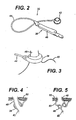
- FIG. 2 is a more detailed perspective view of an exemplary implantable portion for the food intake restriction device of FIG. 1 ;
- FIG. 3 is a perspective view of the adjustable gastric band of FIG. 2 , showing the band positioned around the gastro-esophageal junction of a patient;
- FIG. 4 is a cross-sectional view of the adjustable gastric band of FIG. 2 , shown in a deflated configuration
- FIG. 5 is a cross-sectional view of the adjustable gastric band of FIG. 2 , shown in an inflated configuration to create a food intake restriction;
- FIG. 6 is a side, partially cross-sectioned view of the injection port shown in FIG. 2 ;
- FIG. 7 is an isometric view of the retaining cover shown in FIG. 6 ;
- FIG. 8 is an isometric view of the pressure sensor shown in FIG.6 ;
- FIG. 9 is a side cross-sectional view illustrating an exemplary pressure sensing system
- FIG. 10 is a simplified schematic of the variable resistance circuit of pressure sensing system of FIG. 9 ;
- FIG. 11 is a side, cross-sectional view of an alternative exemplary pressure sensing system
- FIG. 12 is a block diagram representing a pressure measurement system associated with the pressure sensing system of FIGS. 9 and 11 ;
- FIG. 13 is a side, cross-sectional view of an alternative exemplary pressure sensing system
- FIG. 14 is a block diagram representing a pressure measurement system associated with the pressure sensing system of FIG. 13 ;
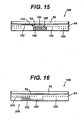
- FIG. 15 is a side, cross-sectional view of an alternative pressure sensing system
- FIG. 16 is a side, cross-sectional view of an alternative pressure sensing system
- FIG. 17 is a block diagram representing a pressure measurement system associated with the pressure sensing systems of FIGS. 15 and 16 ;
- FIG. 18 is a graph indicating a pressure signal from the pressure sensing system, such as may appear on an external monitor display during interrogation by a user;
- FIG. 19 is a side, cross-sectional view of an alternative exemplary pressure sensing system not belonging to the invention.
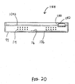
- FIG. 20 is a side, cross-sectional view of an alternative exemplary pressure sensing system not belonging to the invention.
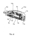
- FIG. 21 is a perspective, cross-sectional view of an alternative exemplary pressure sensing system not belonging to the invention.
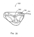
- FIG. 22 is a perspective view of an exemplary sense head
- FIG. 23 a plan view of the sense head of FIG. 22 ;
- FIG. 24 is a side, cross-sectional view of the sense head of FIG. 23 , taken along line 24-24;
- FIG. 25 is a side, cross-sectional view of the sense head of FIG. 23 , taken along line 25-25;
- FIG. 26 is a plan view of an alternative exemplary sense head
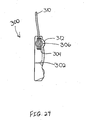
- FIG. 27 is a perspective view of an exemplary display device suitable for coupling with the sense head of FIG. 22 ;
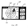
- FIG. 28 is an exemplary graphical display suitable for the display device of FIG. 27 ;
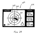
- FIG. 29 is the graphical display of FIG. 28 indicating suitable positioning of the sense head of FIG. 22 ;
- FIG. 30 is a perspective exploded view of an exemplary syringe system with pressure sensor and display device
- FIG. 31 is a cross-sectional view of a pressure sensing portion of the syringe system of FIG. 32 ;
- FIG. 32 is a perspective view of an exemplary infrared communicator suitable for use with the syringe system of FIG. 30 ;
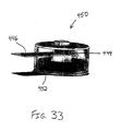
- FIG. 33 is a perspective view of an exemplary RF communicator suitable for use with the syringe system of FIG. 30 ;
- FIG. 34 is a schematic view of an alternative exemplary pressure sensing syringe system
- FIG. 35 is a perspective view of a reusable sensor portion of the pressure sensing syringe system of FIG. 34 ;
- FIG. 36 is a partial perspective view of a disposable cap portion of the pressure sensing syringe system of FIG. 34 ;
- FIG. 37 is a perspective exploded view of an alternative syringe with pressure sensor
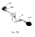
- FIG. 38 a perspective view of a gastric band system with a pressure sensor positioned at the gastric band, which does not belong to the invention
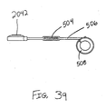
- FIG. 39 is a schematic view of a gastric band system with a pressure sensor positioned within the catheter;
- FIG. 40 a perspective view of a gastric band system with an alternative pressure sensor positioned along the catheter;
- FIG. 41 is a schematic view of a gastric band system with a removable pressure sensor positioned along the catheter;
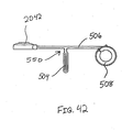
- FIG. 42 is a schematic view of a gastric band system with a pressure sensor and alternative catheter configuration.
- FIG. 43 is a perspective view of a gastric band system with a pressure sensor positioned at the gastric band buckle, which does not belong to the invention.
- FIG. 1 illustrates a food intake restriction system 30.
- System 30 comprises a first portion, identified generally as 32, implanted inside of a patient 34, and a second portion, identified generally as 36, located external to the patient.
- Implanted portion 32 comprises an adjustable gastric band 38 positioned on the upper portion of the patient's stomach 40.
- Adjustable band 38 may include a cavity made of silicone rubber, or another type of biocompatible material, that inflates inwardly against stomach 40 when filled with a fluid.
- band 38 may comprise a mechanically adjustable device having a fluid cavity that experiences pressure changes with band adjustments, or a combination hydraulic/mechanical adjustable band.
- An injection port 42 which will be described in greater detail below, is implanted in a body region accessible for needle injections and/or telemetry communication signals.
- injection port 42 fluidly communicates with adjustable band 38 via a catheter 44.
- a surgeon may position and permanently implant injection port 42 inside the body of the patient in order to perform adjustments of the food intake restriction or stoma.
- gastric band systems such as implantable portion 32 have evolved greatly during recent years so that the patient may derive optimal therapeutic effect with minimal complications.
- the surgeon typically implants injection port 42 in the lateral, subcostal region of the patient's abdomen under the skin and layers of fatty tissue.
- the surgeon may also implant injection port 42 on the sternum of the patient.
- FIG. 2 illustrates an exemplary adjustable gastric band in greater detail.
- band 38 includes a variable volume cavity 46 that expands or contracts against the outer wall of the stomach to form an adjustable stoma for controllably restricting food intake into the stomach.
- a physician may decrease the size of the stoma opening by adding fluid to variable volume cavity 46 or, alternatively, may increase the stoma size by withdrawing fluid from the cavity. Fluid may be added or withdrawn by inserting a needle into injection port 42. Alternatively, fluid may be transferred in a non-invasive manner between band 38 and injection port 42 using telemetry command signals.
- the fluid may be, but is not restricted to, a 0.9 percent saline solution.
- FIG. 3 shows the adjustable gastric band 38 of FIG. 2 applied about the gastro-esophageal junction of a patient.
- band 38 at least substantially encloses the upper portion of stomach 40 near the junction with esophagus 48.
- FIG. 4 is a sectional view of band 38, showing the band in a deflated configuration. In this view, band 38 contains little to no fluid, thereby maximizing the size of the stoma opening into stomach 40.
- FIG. 5 is a cross-sectional view of band 38 and stomach 40, similar to FIG. 4 , showing band 38 in an inflated, fluid-filled configuration.
- FIG. 5 also schematically illustrates the dilation of esophagus 48 above band 38 to form an upper pouch 50 beneath the diaphragm muscle 52 of the patient.
- external portion 36 of food restriction system 30 comprises a pressure-reading device 60 electrically connected (in this embodiment via an electrical cable assembly 62) to a control box 64.
- Control box 64 includes a display 66, one or more control switches 68, and an external control module, which will be explained in further detail below.
- Control box 64 may be configured for use, for example, in a physician's office or examination room. Some ways to mount control box 64 include placement upon a desktop, attachment to an examination table, or hanging on a portable stand. Control box 64 may also be configured for carrying in the physician's lab coat pocket, holding by hand, or placing upon the examination table or the reclining patient.
- Electrical cable assembly 62 may be detachably connected to control box 64 or pressure-reading device 60 to facilitate cleaning, maintenance, usage, and storage of external portion 36 of system 30.
- Pressure-reading device 60 non-invasively measures the pressure of the fluid within implanted portion 32 even when injection port 42 is implanted beneath thick (at least over 10 centimeters) subcutaneous fat tissue. The physician may hold pressure-reading device 60 against the patient's skin near the location of injection port 42 in the patient and observe the pressure reading on display 66 of control box 64.
- Pressure-reading device 60 may also be removably attached to the patient, such as during a prolonged examination, using straps, adhesives, and other well-known methods. Pressure-reading device 60 operates through conventional cloth or paper surgical drapes, and may also include a disposal cover (not shown) that may be replaced for each patient.
- injection port 42 containing a pressure sensing system for non-invasively measuring the fluid pressure within implanted portion 32.
- injection port 42 comprises a rigid housing 70 having an annular flange 72 containing a plurality of attachment holes 74 for fastening the injection port to tissue in a patient.
- a surgeon may attach injection port 42 to the tissue, such as the fascia covering an abdominal muscle, using any one of numerous surgical fasteners including suture filaments, staples, and clips.
- Injection port 42 further comprises a septum 76 typically made of a silicone rubber and compressively retained in housing 70.
- Septum 76 is penetrable by a Huber needle, or a similar type of injection instrument, for adding or withdrawing fluid from the port. Septum 76 self-seals upon withdrawal of the syringe needle to maintain the volume of fluid inside of injection port 42.
- Injection port 42 further comprises a reservoir 80 for retaining a working fluid and a catheter connector 82.
- Connector 82 attaches to catheter 44, shown in FIG. 2 , to form a closed hydraulic circuit between reservoir 80 inside of injection port 42 and cavity 46 within adjustable band 38. Fluid from reservoir 80 may be used to expand the volume of band cavity 46. Alternatively, fluid may be removed from cavity 46 and retained in reservoir 80 in order to temporarily decrease the volume of cavity 46.
- Housing 70 and connector 82 may be integrally molded from a biocompatible polymer or constructed from a metal such as titanium or stainless steel.
- a pressure sensing system is provided in injection port 42 to measure the fluid pressure within the closed hydraulic circuit of implanted portion 32.
- the pressure within the circuit corresponds to the amount of restriction applied by adjustable band 38 to the patient's stomach. Accordingly, measuring the fluid pressure enables a physician to evaluate the restriction created by a band adjustment. Fluid pressure may be measured before, during and/or after an adjustment to verify that the band is properly adjusted.
- the pressure sensing system comprises a sensor 84 positioned at the bottom of fluid reservoir 80 within housing 70.
- a retaining cover 86 extends above pressure sensor 84 to substantially separate the sensor surface from reservoir 80, and protect the sensor from needle penetration.
- Retaining cover 86 may be made of a ceramic material such as, for example, alumina, which resists needle penetration yet does not interfere with electronic communications between pressure sensor 84 and pressure-reading device 60. Retaining cover 86 includes a vent 90 that allows fluid inside of reservoir 80 to flow to and impact upon the surface of pressure sensor 84.
- FIG. 7 is an isometric view of retaining cover 86 illustrating vent 90 in the bottom surface of the cover.
- FIG. 8 is an isometric view of the exterior of pressure sensor 84.
- the exterior of pressure sensor 84 includes a strain element having a deformable surface.
- the strain element is a diaphragm 92.
- Diaphragm 92 may be formed by thinning out a section of a wall in titanium reservoir 80.
- Diaphragm 92 may be made of titanium or another similar material, and have a thickness between 0.0025 cm and 0.005 cm (0.001" and 0.002"). While the embodiments show a diaphragm as the strain element, other strain elements may be used to convert fluid pressure to a mechanical displacement.
- Pressure sensor 84 is hermetically sealed within a housing 94 to prevent fluid infiltrating and effecting the operation of the sensor. Housing 94 is sealed to port housing 70 to prevent the loss of fluid from the injection port 42. Diaphragm 92 is hermetically sealed to sensor housing 94 to prevent fluid from passing around the edges of the diaphragm and into the internal components of the sensing system. As fluid flows through vent 90 in reservoir 80, the fluid impacts upon the surface of diaphragm 92. The fluid flow through vent 90 enables diaphragm 92 to respond to fluid pressure changes within the hydraulic circuit and convert the pressure changes into a mechanical displacement.
- FIG. 9 is a side sectional view of pressure sensor 84, taken along line A-A of FIG. 8 , illustrating a first embodiment 88 for measuring fluid pressure.
- the mechanical displacement of diaphragm 92 is converted to an electrical signal by a pair of variable resistance, silicon strain gauges 96, 98.
- Strain gauges 96, 98 are attached to diaphragm 92 on the side opposite the working fluid in reservoir 80.
- Strain gauge 96 is attached to a center portion of diaphragm 92 to measure the displacement of the diaphragm.
- the second, matched strain gauge 98 is attached near the outer edge of diaphragm 92.
- Strain gauges 96, 98 may be attached to diaphragm 92 by adhesives, or may be diffused into the diaphragm structure. As the fluid pressure within band 38 changes, the surface of diaphragm 92 deforms up or down within the surface of housing 94. This deformation of diaphragm 92 produces a resistance change in the center strain gauge 96.
- strain gauges 96, 98 form the top two resistance elements of a half-compensated, Wheatstone bridge circuit 100.
- Strain gauge 98 is matched to strain gauge 96 and athermalizes the Wheatstone bridge circuit.
- Differential amplifiers 102, 104 are connected to bridge circuit 100 to measure the change in potential within the bridge circuit due to the variable resistance strain gauges. In particular, differential amplifier 102 measures the voltage across the entire bridge circuit, while differential amplifier 104 measures the differential voltage across the strain gauge half of bridge circuit 100.
- a fully compensated Wheatstone bridge circuit could also be used to increase the sensitivity and accuracy of the pressure sensing system.
- four strain gauges are attached to the surface of diaphragm 92, rather than only two strain gauges as shown in FIG. 9 .
- the output signals from differential amplifiers 102, 104 are applied to a microcontroller 106.
- Microcontroller 106 is integrated into a circuit board 110 within housing 94.
- a temperature sensor 112 measures the temperature within the implanted port and inputs a temperature signal to microcontroller 106.
- Microcontroller 106 uses the temperature signal from sensor 112 to compensate for variations in body temperature and residual temperature errors not accounted for by strain gauge 98. Compensating the pressure measurement signal for variations in body temperature increases the accuracy of the pressure sensing system.
- a TET/telemetry coil 114 is located within housing 94. Coil 114 is connected to a capacitor 116 to form a tuned tank circuit for receiving power from external portion 36, and transmitting the pressure measurement to pressure reading device 60.
- FIG. 11 is a side, sectional view similar to FIG. 9 , showing a second embodiment 118 for the pressure sensing system of the present invention.
- a MEMS sensor 120 is provided within housing 94 to measure the mechanical deformation of diaphragm 92 and produce an electrical signal proportional to the pressure within adjustable band 38.
- a sealed, silicone oil chamber 122 is provided between diaphragm 92 and MEMS sensor 120. Oil chamber 122 protects MEMS sensor 120 and transfers the mechanical displacements of diaphragm 92 to the sensor.
- MEMS sensor 120 outputs an electrical signal to microcontroller 106 indicative of the fluid pressure in reservoir 80.
- Microcontroller 106 inputs the signal from the MEMS sensor 120 and a temperature signal from temperature sensor 112, and calculates the pressure measurement.
- the pressure measurement is transmitted to pressure reading device 60 in external portion 36 using telemetry signals, as will be described in more detail below.
- FIG. 12 is a block diagram of a pressure measurement system.
- an external control module 126 of the system includes a primary TET coil 130 for transmitting a power signal to the internal control module, indicated generally as 132.
- Primary TET coil 130 is located in pressure reading device 60 shown in FIG. 1 .
- a TET drive circuit 134 controls the application of a power signal to primary TET coil 130.
- TET drive circuit 134 is controlled by a microprocessor 136 having an associated memory 138.
- a graphical user interface 140 is connected to microprocessor 136 for controlling the data shown on display 66.
- External control module 126 also includes a primary telemetry transceiver 142 for transmitting interrogation commands to and receiving response data, including fluid pressure readings, from implant control module 132.
- Primary transceiver 142 is electrically connected to microprocessor 136 for inputting and receiving command and data signals.
- Primary transceiver 142 resonates at a selected RF communication frequency to generate a downlink alternating magnetic field 146 that transmits command data to implant control module 132.
- a power supply 150 supplies energy to external control module 126 in order to power system 30.
- An ambient pressure sensor 152 is connected to microprocessor 136.
- Microprocessor 136 uses the signal from ambient pressure sensor 152 to adjust the pressure reading for variations in atmospheric pressure due to, for example, variations in barometric conditions or altitude, in order to increase the accuracy of the pressure measurement.
- FIG. 12 also illustrates internal control module 132 implanted beneath the patient's skin 154.
- Internal control module 132 is located within housing 94 of injection port 42.
- a secondary TET/telemetry coil 156 in internal control module 132 receives power and communication signals from external control module 126.
- Coil 156 forms a tuned tank circuit that is inductively coupled with either primary TET coil 130 to power the implant, or primary telemetry coil 144 to receive and transmit data.
- a telemetry transceiver 158 controls data exchange with coil 156.
- internal control module 132 includes a rectifier/power regulator 160, microcontroller 106 described above, a memory 162 associated with the microcontroller, temperature sensor 112, pressure sensor 84 and a signal conditioning circuit 164 for amplifying the signal from the pressure sensor.
- Internal control module 132 transmits the temperature adjusted pressure measurement from pressure sensor 84 to external control module 126. In external module 126, the received pressure measurement signal is adjusted for changes in ambient pressure and shown on display 66.
- FIG. 13 is a side, sectional view showing a third exemplary embodiment 170 for measuring fluid pressure.
- internal control module 132 is powered by an internal power supply such as, for example, a battery 172.
- Battery 172 replaces primary and secondary TET coils 130, 156 for powering microcontroller 106 and the other internal components.
- the pressure sensing system includes a pair of strain gauges 96, 98 as in first embodiment 88, for measuring the mechanical deformations of diaphragm 92 corresponding to pressure changes in band 38. Strain gauges 96, 98 are incorporated into a balanced, thermally compensated bridge circuit for measuring pressure differentials within the closed fluid circuit of the implant.
- FIG. 14 is a block diagram of the pressure measurement system in accordance with the third examplary embodiment 170 shown in FIG. 13 .
- an internal power supply is used to power internal control module 176 rather than a TET power system as in the first embodiment.
- the power source for implanted portion 32 is battery 172 rather than the TET primary coil 130 and secondary coil 156 shown in FIG. 12 .
- secondary, implanted coil 156 is used solely for data communication between the internal and external control modules.
- a power regulator 174 is provided to control power from battery 172 in order to conserve and extend the life of the battery.
- FIG. 15 illustrates a fourth exemplary embodiment 180 for measuring fluid pressure within adjustable band 38, in which a passive system is utilized for measuring pressure changes within the working fluid.
- a variable capacitance 182 is attached to diaphragm 92 in order to measure the mechanical deformations of the diaphragm.
- Variable capacitance 182 includes a first plate 184 attached near the center of diaphragm 92 on the side opposite fluid reservoir 80.
- a second capacitor plate 186 is fixed in position within housing 94 by a capacitor mount 188.
- Each of the capacitor plates 184, 186 is connected to an inductance coil 190, as shown by lines 192, to form a resonant circuit.
- capacitor plate 184 When the fluid pressure within reservoir 80 increases or decreases due to, for instance, changes in the peristaltic pressure against band 38, the position of capacitor plate 184 varies with the deformation of diaphragm 92. As fluid pressure increases, diaphragm 92 pushes first capacitor plate 184 closer to second capacitor plate 186, thereby increasing the capacitance and decreasing the resonant frequency. Likewise, when the hydraulic pressure decreases within the closed implant circuit, first capacitor plate 184 moves with diaphragm 92 in a direction away from second plate 186, thereby decreasing the capacitance within the resonant circuit and increasing the resonant frequency.
- FIG. 16 shows a fifth exemplary embodiment 196 for measuring fluid pressure in accordance with the present invention.
- Fifth embodiment 196 is an alternative embodiment for a passive pressure sensing system, in which a variable inductance coil 200 converts the mechanical deformations of diaphragm 92 into a pressure measurement signal.
- inductance coil 200 is a flat coil spaced beneath diaphragm 92.
- a fixed capacitance 202 is connected to inductance coil 200, as shown by lines 204, to form an LC resonant circuit 206.
- diaphragm 92 deforms up and down in response to pressure variations in the working fluid, the inductance of coil 200 varies.
- diaphragm 92 deforms in the direction of coil 200, thereby decreasing the inductance of coil 200 due to eddy current coupling between the metal diaphragm and coil. Conversely, when fluid pressure decreases, diaphragm 92 deforms away from coil 200, thereby decreasing the eddy current coupling and increasing the inductance of the coil. Accordingly, the inductance of coil 200 is inversely proportional to the pressure of the working fluid. As the inductance of coil 200 changes, the resonant frequency of the LC circuit 206 changes.
- FIG. 17 is a block diagram of a pressure measurement system for the fourth and fifth exemplary embodiments 180, 196 of the invention.
- microprocessor 136 controls an inducing coil circuit 208 and inducing coil 210.
- Microprocessor 136 varies the frequency of inducing coil 210 to magnetically couple the coil with LC circuit 206 in implanted portion 32, as indicated by line 212.
- the frequency at which the internal and external coils couple will vary with the resonant frequency of the implanted LC circuit 206.
- the resonant frequency of the implanted LC circuit will vary with the fluid pressure within band 38.
- the variation in resonant frequency is measured by microprocessor 136 through inducing coil circuit 208. Once detected, the resonant frequency may be compared to known pressures at designated frequencies to determine the fluid pressure within band 38.
- a graphical user interface 140 in external module 214 displays the measured fluid pressure on display 66.
- FIG. 18 is a graphical representation of a pressure signal 216 from the pressure sensing system, such as may appear on display 66 during interrogation by a user.
- the fluid pressure is initially measured by pressure reading device 60 while the patient is stable, resulting in a steady pressure reading as shown.
- an adjustment is applied to band 38 to decrease the stoma size.
- the pressure sensing system continues to measure the fluid pressure and transmit the pressure readings through the patient's skin to device 60.
- the pressure reading rises slightly following the band adjustment.
- the patient is then asked to drink a liquid to check the accuracy of the adjustment.
- the pressure sensing system continues to measure the pressure spikes due to the peristaltic pressure of swallowing the liquid, and transmit the pressure readings to external module 36 for display.
- the present invention provides the physician with an accurate, real-time visualization of the patient's response to the adjustment.
- This instantaneous, active display of recorded pressure data enables the physician to perform more accurate band adjustments.
- the data may be displayed over time to provide a pressure verses time history.
- the pressure sensing system of the invention may also be used to measure pressure variations in the restriction device at various intervals during treatment. Periodic pressure readings enable the pressure sensing system to function as a diagnostic tool, to ensure that the food intake restriction device is operating effectively.
- the pressure sensing system may be utilized to detect a no pressure condition within the band, indicating a fluid leakage.
- the system may be used to detect excessive pressure spikes within the band, indicating a kink in catheter 44 or a blockage within the stoma.
- the pressure sensing system of the invention also enables a patient to track their own treatment, utilizing an external monitor, such as external device 36, at home.
- an external monitor such as external device 36
- the patient may routinely download pressure readings to their physician's office, thereby reducing the number of office visits required to monitor the patient's treatment.
- the patient could perform pressure readings at home and notify their physician when the band pressure drops below a specified baseline or exceeds a threshold, indicating the need for an adjustment of the device.
- the pressure sensing system of the invention thus has benefits as both a diagnostic and a monitoring tool during patient treatment with a bariatric device.
- Exemplary sensor systems 1088, 1188 suitable for incorporation into port 42 are shown in FIGS. 19-20 .
- Each of these pressure sensing systems 1088, 1118 comprise an upper member 1092 and a housing 94.
- pressure sensing systems 1088, 1118 may be positioned beneath retaining cover 86 of port 42.
- upper member 1092 may be integral with retaining cover 86, such that upper member 1092 provides a bottom for retaining cover 86 or reservoir 80.
- Other suitable configurations will be apparent to those of ordinary skill in the art.
- upper member 1092 is in fluid communication with fluid located within port 42, such that the pressure of such fluid is exerted against upper member 1092.
- Each of these pressure sensing systems 1088, 1118 further comprise a microcontroller 106, a TET/telemetry coil 114, and a capacitor 116. Each of these pressure sensing systems 1088 may further comprise a temperature sensor (not shown). Microcontroller 106, TET/telemetry coil 114, and capacitor 116 may be configured and may function in a manner similar to the configuration and function of these components 106, 114, 116 described above.
- a fluid access port 1094 is provided in upper member 1092, and is in fluid communication with a pressure sensor 1120.
- a hermetic seal 1122 secures pressure sensor 1120 to the bottom of upper member 1092.
- Pressure sensor 1120 is configured to sense pressure of fluid adjacent to upper member 1092, which is communicated to pressure sensor 1120 via fluid access port 1094.
- Pressure sensor 1120 is further in communication with microcontroller 106, such that pressure measurements obtained using pressure sensor 1120 may be communicated to or through microcontroller 106 and thus via coil 114 to an external telemetry device.
- a pressure sensor 1180 having a can-like configuration is positioned within upper member 1092, and protrudes above upper member 1092.
- Pressure sensor 1180 has a metal cap 1182 that acts as a diaphragm, and is hermetically sealed. Pressure sensor 1180 and/or cap 1182 may also be hermetically sealed relative to adjacent conductive and/or electronic components to provide electrical isolation.
- pressure sensor 1180 is configured to sense pressure of fluid adjacent to upper member 1092.
- pressure sensor 1180 is further in communication with microcontroller 106, such that pressure measurements obtained using pressure sensor 1180 may be communicated to or through microcontroller 106 and thus via coil 114 to an external telemetry device.
- pressure sensor 1180 may further comprise silicon oil or gel to facilitate uniformity of pressure transfer from cap 1182, to facilitate electrical isolation of pressure sensor 1180, or for any other purpose.
- silicon oil or gel any substitute for silicon oil or gel may be used, or the same may be omitted altogether.
- FIG. 21 shows another exemplary port 1142.
- Port 1142 of this example comprises an upper housing 1170, which is secured to a lower housing 1172.
- Port 1142 further comprises a septum 76 and a retainer 1176.
- Retainer 1176 is secured to upper housing 1170, and is configured to retain septum 76.
- Port 1142 further comprises a reservoir 80 and a catheter connector 82 in fluid communication with reservoir 80.
- a plate 1178 is positioned at the bottom of reservoir 80, and has a plurality of vents 90 formed therethrough.
- a pressure measurement chamber 1188 is located beneath plate 1178, and is in fluid communication with reservoir 80 via vents 90.
- a pressure sensor 1190 is positioned within pressure measurement chamber 1188, and is operable to measure the pressure of fluid within port 1142.
- pressure sensors 1120, 1180, 1190 each comprise a wireless pressure sensor provided by CardioMEMS, Inc. of Atlanta, Georgia, though a suitable MEMS pressure sensor may be obtained from any other source.
- MEMS pressure sensor 1190 comprises a pressure sensor described in U.S. Patent No. 6,855,115 .
- each pressure sensor 1120, 1180, 1190 is configured to wirelessly communicate pressure data to an external telemetry device.
- pressure sensors 1120, 1180, 1190 each comprise a silicon dye. Of course, any other type of pressure sensor may be used.
- port 1142 shown in FIG. 21 may further comprise any additional components, including but not limited to a TET/telemetry coil, a capacitor, a microcontroller, a battery, etc. (not shown). Still other variations will be apparent to those of ordinary skill in the art.
- FIGS. 22-25 show an exemplary sense head 300, which is operable to externally sense the location and orientation of port 42, 1142.
- Sense head 300 of this example comprises a needle window 302, a set of horizontal coils 304, a set of vertical coils 306, a TET coil (not shown), and a cable 310.
- the TET coil is wrapped around a generally triangular bobbin (not shown), though any other configuration may be used.
- the TET coil is tuned in parallel with a low ESR capacitor at 50 kHz to form a parallel tuned tank circuit.
- Coil 114 of port 42 is tuned in series with a capacitor such that the resonant impedance is minimized at a resonant frequency of 50 kHz. With an input power of 5 W on the TET coil, coil 114 may deliver approximately 10 mW of power.
- any other configurations and parameters may be used.
- Each vertical coil 306 of sense head 300 is positioned perpendicularly within a corresponding horizontal coil 304. While three horizontal coils 304 and three vertical coils 306 are shown, it will be appreciated that any suitable number of coils 304, 306 may be used. In addition, while the coils 304, 306 are shown as being in a generally triangular arrangement, it will be appreciated that any other suitable arrangement or configuration may be used. Cable 310 is in communication with coils 304, 306, and is further in communication with a display device 350 as will be described in greater detail below. Of course, sense head 300 may be in communication with any other external device via wire, wirelessly, or otherwise.
- Sense head 300 of the present example is configured to communicate with an injection port, such as injection port 42 by way of example only. It will be appreciated that sense head 300 may communicate with any other injection port or device, including but not limited to alternative ports described herein and variations thereof. It will be understood after reviewing the discussion herein, however, that with some embodiments, the type or amount of metal within a port may have an adverse effect on operation of the port and/or sense head 300. For instance, such effects may be in the form of undesirable eddy currents, to the extent that eddy currents are undesirable. To the extent that a metal port housing provides undesirable results it will be appreciated that a coil 114 may be positioned outside of such metal and hermetically wired to a pressure sensor 87 or to other port components. However, such measures are not necessary with port 42 of the present example.
- sense head 300 is operable to provide power to port 42 via the TET coil. Sense head 300 is also operable to detect the position and orientation of port 42, as will be described in greater detail below. Furthermore, sense head 300 is operable to receive pressure data and other data communicated from port 42 in a manner similar to pressure reading device 60, described above. While location, orientation, and pressure-related communications will be described in greater detail below, those of ordinary skill in the art will appreciate that any other types of information may be communicated between port 42 and sense head 300 in any other suitable manner.
- sense head 300 is placed adjacent to a patient 34 in a region generally near port 42.
- sense head 300 may be used to determine the location and orientation of port 42, thereby permitting a user to position sense head 300 directly over or sufficiently near port 42.
- the user may insert a needle 430 of syringe 400 through needle guide 302 of sense head 300 and reach septum 76 of port 42 on the first try. The user may then use syringe 400 to adjust the pressure of fluid within implanted portion 32.
- horizontal coils 304 are configured to sense an RF signal provided by coil 114 in port 42. It will be appreciated that characteristics of such RF signal may vary as a function of the position of sense head 300 relative to port 42.
- Display device 350 may receive indications of such RF signals from each horizontal coil 304, and may process these signals through a logic operable to compare the signal picked up at each horizontal coil 304.
- Sense head 300 may thus be used to determine the position of port 42 through triangulation. For instance, when sense head 300 is positioned directly over port 42, the three received signals may have an approximately equal amplitude, and a phase shift of approximately zero.
- sense head 300 may be moved around adjacent patient 34 until the differences between the amplitudes and phases of the RF signal sensed at horizontal coils 304 are minimized.
- a display device 350 may further comprise a logic operable to provide a visual representation to the user indicating the relative positioning of sense head 300 and port 42, and further provide a particular indication when sense head 300 is positioned directly over port 42.
- Sense head 300 may further comprise a feature operable to visually display location information.
- sense head 300 comprises a plurality of LEDs 312, which are arranged in a "plus sign"-like configuration.
- LEDs 312 may provide a visual indication to the user as to the relative positioning of sense head 300 and port 42.
- lit LEDs 312 may represent position of port 42 relative to sense head 300. For instance, if sense head 300 needs to be moved down and to the right in order to be positioned directly over port 42, the right-most and lower-most LEDs 312 may be lit.
- LEDs may provide feedback indicating such proximity as sense head 300 is moved, until the center LED 312 is lit to indicate that sense head 300 is positioned generally over port 42.
- the user may then desire to refer to display device 350, as will be described in greater detail below, to further adjust positioning of sense head 300.
- LEDs 312 may be arranged in any suitable configuration other than a "plus sign.”
- Such alternative configurations may comprise a Cartesian representation, a polar representation, a numerical representation, or any other type of representation. By way of example only, a star or compass rose configuration may be used.
- an array of LEDs 312 are provided, and are operable to be selectively lit in the form of an arrow indicating direction. The length of such an arrow may further be varied to indicate distance. It will also be appreciated that additional LEDs 312 may be used to increase spatial resolution of distance and/or direction indicated by such LEDs 312. Of course, any suitable alternative to LEDs 312 may be used, including but not limited to an LCD screen or other display.
- a logic configured to process signals received by horizontal coils 304 to provide positioning feedback through LEDs 312 resides within sense head 300.
- such logic resides in display device 350, and is communicated to LEDs 312 in part through cable 310.
- the logic for driving LEDs 312 resides within both sense head 300 and display device 350. Still other suitable locations for logic to drive LEDs 312, and other ways in which LEDs 312 may be driven, will be apparent to those of ordinary skill in the art. It will also be appreciated that, as with any other component and feature described herein, LEDs 312 may simply be omitted altogether.
- sense head 300 With sense head 300 placed in an initial position adjacent to a patient 34 in a region generally near port 42, vertical coils 306 configured to sense an RF signal provided by coil 114 in port 42. It will be appreciated that characteristics of such RF signal may vary as a function of the orientation (e.g., pitch, yaw, roll, attitude, etc.) of sense head 300 relative to port 42.
- Display device 350 may receive indications of such RF signals from each vertical coil 306, and may process these signals through a logic operable to compare the signal picked up at each vertical coil 306.
- the three received signals When sense head 300 is oriented parallel with port 42, the three received signals may have an approximately equal amplitude, and a phase shift of approximately zero.
- display device 350 may further comprise a logic operable to provide a visual representation to the user indicating the relative orientation of sense head 300 and port 42, and further indicate when sense head 300 is oriented substantially parallel with port 42.
- sense head 300 and port 42 are configured such that orientation characteristics may detected based on the phase relationship between signals emitted by coil 114 and within sense head 300 (e.g., a launch/drive signal from a TET coil in sense head 300). For instance, if the signals are in phase, such a relationship may indicate that port 42 is oriented parallel with sense head 300 and that septum 76 is facing sense head 300; whereas the signals being 90° out of phase may indicate that port 42 is perpendicular to sense head 300; while the signals being 180° out of phase may indicate that port 42 is flipped over relative to sense head 300 (e.g., septum 76 is facing inward toward the center of patient 34). Other orientations may be detected based on corresponding phase relationships.
- coil 114 in port 42 may emit a pattern of pulses when sense head 300 is passed over port 42, such as two short pulses followed by a longer pulse (e.g., about 3-4% longer than the short pulses) when port 42 is right side up. When port 42 is flipped 180°, the pattern may be reversed.
- Sense head 300 may receive these signals, and sense head 300 or any other device (e.g., display device 350, etc.) may process such signals, such that the user may be provided with an audio or visual indication relating to the orientation of port 42. Accordingly, it will be appreciated that vertical coils 306 are not necessarily needed to obtain orientation information. Other suitable structures and techniques for determining orientation information will be apparent to those of ordinary skill in the art.
- needle window 303 is offset from the center of sense head 301, but is otherwise configured similar to sense head 300. Such an offset of needle window 303 may reduce the likelihood that the housing of sense head 301 will physically interfere with external anatomical structures of patient 34 where such interference would otherwise create difficulties in positioning the centered needle window 302 of sense head 300 over port 42.
- the offset of needle window 303 as shown in FIG. 26 is merely exemplary, and it will be appreciated that needle window 303 may be located elsewhere (e.g., proximate to an edge or corner of the housing of sense head 301, etc.).
- a corrective constant e.g., a vector
- Such a corrective constant may represent the displacement (e.g., in terms of distance and direction) of needle window 303 relative to the center of sense head 301 (or relative to the center of the arrangement of coils 304, 306).
- the position of the center of sense head 301 relative to port 42 may first be found by comparing RF signals (e.g., in terms of phase and amplitude) received by horizontal coils 304 (thereby obtaining a "determined position"). The corrective constant may then be added to that determined position to further determine the position of needle window 303 relative to port 42.
- the properties of RF signals received by coils 304 may have one or more characteristic disparities (or one or more characteristic disparity ranges) when needle window 303 is positioned directly over port 42, such that the algorithm may treat that disparity in a manner similar to the minimized phase and amplitude differences of RF signals received by coils 304 in sense head 300.
- the algorithm may treat such disparity as a target to be reached.
- the characteristic disparities in the properties of RF signals sensed by horizontal coils 304 when needle window 303 is positioned directly over port 42 may be a function of the displacement of the needle window 303 relative to sense head 301, such that the characteristic disparities may be predetermined.
- any other techniques or structures suitable for determining the position of needle window 303 relative to port 42 may be used.
- FIG. 27 shows an exemplary display device 350 that is configured to translate information communicated from the sense head 300 into visual representations readable by a user.
- display device 350 is in communication with sense head 300 via cable 310, but again, any alternative to cable 310 may be used.
- Display device 350 further comprises a graphical display 354, which includes a target display 360, and is illustrated in FIGS. 28-29 .
- the target display 360 of the present example includes a crosshairs 362 and an arrow indicator 364.
- the target display 360 of this example is operable to render location and orientation information relating to the location and orientation of sense head 300 relative to port 42.
- the position of the tip 366 of arrow indicator 366 relative to the center 364 of crosshairs 362 may serve to indicate the position of needle window 302 relative to the center of port 42 (e.g., septum 76).
- the center 364 of crosshairs 360 may represent the center of septum 76; with the tip 366 of arrow indicator 366 representing needle window 302.
- the positioning data may be refreshed at any suitable rate, such as in approximate real-time, to provide the user location feedback via targeting display 360. The user may thus move sense head 300 until targeting display 360 indicates that the needle window 302 is located directly over port 42.
- Orientation data may be rendered via targeting display 360 in terms of the tilt of arrow indicator 366.
- the direction and amount of tilt of arrow indicator 366 may represent the orientation of sense head 300 relative to port 42, such that arrow indicator 366 pivots about its tip 366 to indicate such orientation.
- the orientation data may be refreshed at any suitable rate, such as in approximate real-time, to provide the user orientation feedback via targeting display 360.
- sense head 300 cannot be satisfactorily oriented relative to port 42 (e.g., if port 42 has flipped upside-down or on its side relative to the fascial plane of patient), surgery may be required to re-orient port 42.
- FIG. 29 shows a view of display device 350 with a target display 360 indicating that the sense head 300 is positioned substantially directly over port 42 and substantially parallel with port 42. Accordingly, arrow indicator 366 is positioned over center 364 of crosshairs 362, and pivoted upright (i.e., perpendicular to the screen), such that only the tail 370 of arrow indicator 366 can be seen. Such a display may indicate to the user that a needle 403 inserted straight into needle window 302 will successfully reach septum 76 of port.
- arrow indicator 366 may be shown in red to indicate that insertion of needle 403 through needle window 302 would not be appropriate (e.g., needle 403 would not reach septum 76).
- tail 370 of arrow indicator 366 may be shown in green to indicate that insertion of needle 403 through needle window 302 would be appropriate (e.g., the needle would reach septum 76).
- sense head 300 need not be perfectly parallel with port 42 in order to successfully pass needle 403 through needle window 302 into septum 76. Accordingly, display device 350 may provide an indication showing that needle 403 may successfully reach septum 76 through needle window 302, despite a non-parallel orientation of sense head 300 relative to port 42. For instance, such orientation may be indicated where tail 370 of arrow indicator 366 is within a particular ring of crosshairs 362. Alternatively, such orientation may be indicated by coloring arrow indicator 366 yellow or some other color. Still other ways in which the sufficiency of a non-parallel orientation may be indicated in target display 360 will be apparent to those of ordinary skill in the art.
- sense head 300 cannot be located directly over port 42 without having unsatisfactory orientation of sense head 300 relative to port 42; while sense head 300 may be oriented generally parallel with port 42 when not positioned directly over port 42.
- the septum 76 may nevertheless be reached by needle 403 inserted through needle window 302 if needle 403 is oriented properly with respect to sense head 300 (e.g., at an angle of approximately 80° or a 10° deflection).
- display device 350 may provide an indication showing that needle 403 may successfully reach septum 76 through needle window 302, despite sense head 300 not being positioned directly over port 42.
- orientation may be indicated where tail 370 of arrow indicator 366 is within a particular ring of crosshairs 362.
- orientation may be indicated by coloring arrow indicator 366 yellow or some other color.
- sense head 300 may be configured to obtain depth data indicating the distance from needle window 302 to port 42 (and, hence, depth to septum 76). Such depth data may be represented on display device 350 in a variety of ways. For instance, the depth may be indicated as a numerical value and/or in any other suitable way. In addition to location, orientation, and depth-related information, other geometric information that may be obtained by sense head 300 and communicated to display device 350 will be apparent to those of ordinary skill in the art.
- display device 360 may also display pressure data communicated from port 42 to sense head 300.
- display device 350 of the present example comprises a pressure display portion 374.
- pressure display portion 374 provides an initial pressure reading, a baseline pressure, and a peak pressure.
- the initial pressure reading represents the pressure within implanted portion 32 before fluid is added or withdrawn.
- the baseline pressure reading represents the current pressure within implanted portion 32 (e.g., as fluid is being added or withdrawn or after fluid has been added or withdrawn).
- the peak pressure reading represents the peak pressure sensed during peristaltic motion of the stomach.
- any other pressure parameters may be displayed, as may other data such as temperature, etc.
- sense head 300 may be configured to receive pressure data from port 42 in a manner similar to pressure-reading device 60. It will therefore be appreciated that the TET coil of sense head 300 may also serve as a telemetry coil to receive telemetry signals from coil 114 in port 42 indicating pressure or other data. Alternatively an additional coil dedicated to such telemetry may be provided in sense head 300. As yet another variation any of vertical coils 306 and/or horizontal coils 304 may be used for such telemetry. Still other suitable configurations will be apparent to those of ordinary skill in the art.
- sense head 300 and display device 350 may be used to provide approximately real-time pressure measurements to a user before, during, and after the addition or withdrawal of fluid to or from implanted portion 32. For instance, a surgeon may adjust the saline content of implanted portion 32 while patient 34 swallows a fixed amount of water, and may monitor the pressure level in implanted portion via sense head 300 and display device 350 during such activities.
- an optimal pressure adjustment may be determined based on a variety of factors related to pressure data, including but not limited to any of the following: the original baseline pressure; the new baseline pressure; the maximum peristaltic pressure; the minimum peristaltic pressure; the length of a peristaltic contraction; the Fourier transform of a peristaltic contraction data spike; the pressure decay time constant during persistaltic contractions; the total averaged pressure decay time constant during a water swallowing period; the number of peristaltic contractions to swallow a fixed amount of water; one or more forces exerted by an implanted device and/or an anatomical structure; energy of an implanted device or of fluid therein; the fill rate of fluid into an implanted device; the volume of fluid in an implanted device; the capacity of an implanted device; the flow rate of fluid into or within an implanted device; the pressure pulse rate of fluid within an implanted device; a counted number of pressure pulses of fluid within an implanted device; one or more electrical signals communicated from tissue
- display device 350 is operable to receive data indicative of the above-noted factors in any suitable fashion (e.g., from sensors, etc.), and is further operable to automatically process such factors and present the result of such processing to the user.
- display device 350 may be configured to determine an ideal amount of fluid to be added or withdrawn based on such processing of factors, and may simply display a message to the user such as "Add 4 cc's of fluid,” “Withdraw 0.5 cc's of fluid,” or the like. Such messages may be displayed in addition to or in lieu of displaying pressure measurements, changes in pressure, or other data.
- Other suitable processes of any of the above-noted factors or other factors, as well as ways in which results of such processes may be presented to the user will be apparent to those of ordinary skill in the art.
- pressure sensor 84 provides pressure data at an update rate of approximately 20 Hz. Such a rate may provide a telemetry/TET mode cycle completion at approximately every 50 ms.
- coil 114 may provide TET for port 42 for approximately 45 ms to power port 42, then provide telemetry of pressure data for approximately 5 ms.
- any other switching topology may be used. It will also be appreciated that switching between TET and telemetry may be unnecessary.
- port 42 may be active, such that TET is not required.
- a second coil (not shown) may be added to port 42, with one of the coils in port 42 being dedicated to TET and the other to telemetry. Still other alternatives and variations will be apparent to those of ordinary skill in the art.
- pressure data may be represented in a variety of other ways. For instance, a graph may show pressure as a function of time, which may be useful for monitoring pressure during peristaltic activity or for other purposes. It will also be appreciated that absolute values of pressure at particular moments in time need not be displayed, and that display device 350 may instead display changes in pressure value. Other ways in which pressure data or other data may be displayed will be apparent to those of ordinary skill in the art.
- sense head 300 may receive additional data such as temperature measurements taken within implanted portion 32, and display device 350 may comprise logic configured to adjust pressure readings in accordance with a variety of such factors.
- sense head 300 comprises a switch (not shown) which is operable to switch sense head 300 between a positioning mode and a pressure sensing mode.
- the user may switch sense head 300 to positioning mode to obtain location and orientation data to sufficiently position sense head 300 over port 42.
- the user may then switch sense head 300 to pressure sensing mode to obtain pressure measurements before, during, and after the addition or withdrawal of fluid to or from implanted portion 32.
- a similar switch may be provided on display device 350.
- no switch is used, such that sense head 300 is operable for use in a positioning mode and pressure sensing mode simultaneously. Still other possible modes and features for effecting switching between such modes will be apparent to those of ordinary skill in the art.
- sense head 300 may be used in conjunction with a port that has a coil but lacks a pressure sensor. This embodiment does not form part of the invention. In other words, sense head 300 may be used simply to determine the location and orientation of a port. Upon such a determination, pressure data may be obtained from a source other than the port (e.g., from a sensor elsewhere in implanted portion, from a sensor external to the patient, etc.) or not obtained at all. In addition, while examples discussed above include use of sense head 300 with port 42, it will be appreciated that sense head 300 may be used with port 1142.
- sense head 300 may necessitate the inclusion of a TET/telemetry coil in sense head 1142, or some other device(s) operable to transmit signals for reception by coils 304, 306.
- Other variations of sense head 300 and variations of using sense head 300 will be apparent to those of ordinary skill in the art.
- FIGS. 30-31 depicts an exemplary syringe 400 and a display device 420 in communication via a cable 422.
- Syringe 400 comprises a plunger 402, a barrel 404, a pressure sensing component 410, and a needle 430.
- plunger 402, barrel 404, and needle 430 are conventional components.
- barrel 404 has a male luer lock portion 406; and needle 430 has a female luer lock portion 424.
- Plunger 402 has a piston 408 configured to sealingly engage with barrel 404.
- needle 430 comprises a Huber needle.
- any of these components, among others, may be varied.
- Cable 422 has a boot portion 429, which is configured to selectively attach to pressure sensing component 410.
- Boot portion 429 further comprises a feature (not shown) that is operable to electrically engage with pressure sensor 426, and thereby communicate pressure readings obtained by pressure sensor 426 along cable 422.
- a feature may comprise one or more terminals (not shown) or any other feature(s).
- pressure sensing component 410 is fixedly secured to boot portion 429 and cable 422.
- Other suitable configurations will be apparent to those of ordinary skill in the art.
- pressure sensing component 410 comprises a male luer lock portion 412, a female luer lock portion 414, a vertical cylindraceous portion 416, a horizontal cylindraceous portion 418, and a pressure sensor 426.
- Male luer lock portion 412 of pressure sensing component 410 is configured to engage with female luer lock portion 424 of needle 430; while female luer lock portion 414 of pressure sensing component 410 is configured to engage with male luer lock portion 406 of barrel 404.
- pressure sensing component 410 may be retrofitted to a variety of existing syringes.
- a syringe 400 may be constructed having a pressure sensing component 410 or similar feature integrally formed within.
- pressure sensor 426 is positioned within horizontal cylindraceous portion 418, adjacent to an annular flange 428.
- pressure sensor 426 is sealingly secured to annular flange 428.
- boot portion 429 comprises one or more electrodes (not shown) or similar features configured to communicate with and/or receive communications from pressure sensor 426 upon engagement of boot portion 429 with pressure sensing component 410.
- pressure sensor 426 is fixed within boot portion 429, and may be positioned adjacent to annular flange 428 upon engagement of boot portion 429 with pressure sensing portion 410. Alternatively, any other suitable configuration may be used.
- Pressure sensor 426 may be constructed in accordance with any of the pressure sensors described above. Alternatively, pressure sensor 426 may comprise any off-the-shelf pressure sensor suitable for use, or any other type of pressure sensor. In the present example, when syringe 400 is assembled, vertical cylindraceous portion 416 provides a sealed conduit for fluid communication from barrel 404 to needle 430. Vertical cylindraceous portion 416 is further in fluid communication with horizontal cylindraceous portion 418; as is pressure sensor 426. Accordingly, it will be appreciated that pressure sensor 426 may be operable to sense pressure of fluid within syringe 400. It will also be appreciated that pressure sensed by pressure sensor 426 may be communicated to display device 420 via cable 422, and displayed thereon in any suitable format.
- needle 430 is inserted into patient 34 to reach a septum of an injection port (not shown).
- Any suitable port may be used, including but not limited to any of the ports 42, 1142 described above and variations thereof, and any port lacking a pressure sensor.
- needle 430 may be placed in fluid communication with implanted portion 32, such that the pressure of the fluid in implanted portion 32 and the fluid in syringe 400 may be substantially equalized. It will therefore be appreciated that pressure sensed by pressure sensor 426 may be indicative of the pressure of fluid within implanted portion 32.
- Such pressure information may be particularly useful during a process of adjusting pressure within implanted portion 32 via addition of fluid to implanted portion 32 with syringe or withdrawal of fluid from implanted portion 32 with syringe 400.
- syringe 400 may permit simultaneous adjustment and reading of fluid pressure.
- a user may first insert needle 430 into patient 34 to reach the septum 76 of an injection port 42, 1142. Upon pressure equalization, the user may then read the initial pressure via display device 420. It will be appreciated that pressure equalization may be determined by a pressure reading remaining substantially constant. The user may then add or withdraw fluid to or from implanted portion 32 using syringe 400, watching for changes in pressure indicated via display device 420. Because no valve or other mechanism is necessarily required to switch syringe 400 between a pressure sensing mode and an add/withdrawal mode, such pressure readings may be obtained as the user is adding or withdrawing fluid to or from implanted portion 32.
- pressure sensing component 410 and pressure sensor 426 may be considered substantially in-line with the other syringe 400 components.
- the phrase “substantially in-line” shall be read to imply that fluid may be added or withdrawn with syringe 400 substantially contemporaneously with pressure sensing by pressure sensor 426; and that manipulation of a valve or other mechanism is not required to switch between an add/withdrawal mode of syringe 400 and a pressure sensing mode of syringe 400.
- the phrase “substantially in-line” shall not be read to require that a straight line must be able to intersect pressure sensor 426 and all other components of syringe 400.
- Pressure readings may thus be obtained in approximately real-time, as the pressure is adjusted by the user with syringe 400. To the extent that there is a delay between the user's manipulation of syringe 400 and the time the pressure equalizes among syringe 400 and implanted portion 32, the user may simply wait until the pressure reading indicated by display device 420 becomes substantially constant.
- Other suitable uses for syringe 400 and display device 420 will be apparent to those of ordinary skill in the art.
- FIG. 32 depicts an exemplary substitute for cable 422.
- cable 422 of the syringe 400 version shown in FIGS. 30-31 is substituted with a wireless infrared communicator 440.
- Infrared communicator 440 comprises a pair of LED's 442, a battery 444, and a pull-tab 446.
- Infrared communicator 440 is securable to pressure sensing component 410, and is in communication with pressure sensor 426.
- pressure sensor 426 is housed within infrared communicator 440, and is configured to be exposed to the pressure of fluid within pressure sensing component 410 when coupled with pressure sensing component 410.
- pressure exposure may be provided by having pressure sensor 426 in direct contact with fluid in pressure sensing component 410.
- infrared communicator 440 and/or pressure sensing component 410 may comprise a diaphragm or other member operable to communicate pressure forces to pressure sensor 426 positioned between pressure sensor 426 and fluid in pressure sensing component 410.
- pressure sensor 426 is a component of pressure sensing component 410, and infrared communicator 440 is configured to receive pressure data obtained from pressure sensor 426 when coupled with pressure sensing component 410. Still other suitable configurations will be apparent to those of ordinary skill in the art.
- Infrared communicator 440 of the present example is operable to communicate pressure data obtained from pressure sensor 426 via LED's 442 in infrared light. Accordingly, it will be appreciated that display device 420 may be modified to include an infrared sensor (not shown) operable to receive such communications. Battery 444 may be used to provide power to infrared communicator 440. Pull-tab 446 may be initially positioned between battery 444 and a terminal to preserve the life of battery 444 before a first use. The user may thus remove pull-tab 446 before the first use. Alternatively, infrared communicator 440 may comprise a switch or other mechanism for selectively activating battery 444. Other variations will be apparent to those of ordinary skill in the art. It will also be appreciated that this variation of syringe 400 may be used in a manner similar to any of the other variations of syringe 400, as described above.
- FIG. 33 shows yet another exemplary substitute for cable 422.
- cable 422 of the syringe 400 version shown in FIGS. 30-31 is substituted with a wireless radio frequency (RF) communicator 450.
- RF communicator 450 comprises an RF coil 452, a battery 444, and a pull-tab 446.
- RF communicator 450 is securable to pressure sensing component 410, and is in communication with pressure sensor 426.
- pressure sensor 426 may reside within RF communicator 450 or within pressure sensing component 410. other suitable configurations will be apparent to those of ordinary skill in the art.
- RF communicator 450 of the present example is operable to communicate pressure data obtained from pressure sensor 426 via RF coil 452 as an RF signal. Accordingly, it will be appreciated that display device 420 may be modified to include an RF signal receiver (not shown) operable to receive such communications.
- Battery 444 may be used to provide power to RF communicator 450.
- Pull-tab 446 may be initially positioned between battery 444 and a terminal to preserve the life of battery 444 before a first use. The user may thus remove pull-tab 446 before the first use.
- RF communicator 450 may comprise a switch or other mechanism for selectively activating battery 444.
- this variation of syringe 400 may be used in a manner similar to any of the other variations of syringe 400, as described above.
- FIG. 34 shows another exemplary pressure sensing syringe system 1400.
- syringe system 1400 comprises a syringe 400, tubing 1402, a pressure sensing portion 1420, cables 1404, an interface component 1406, and a display device 1408.
- Syringe 400 comprises "T"-joint 1410 having a two-way leur activated valve 1412.
- "T"-joint 1410 is in fluid communication with needle 430 and tubing 1402.
- Two-way luer activated valve 1412 is configured such that it opens when "T"-joint 1410 is coupled with male luer lock portion 406 of syringe 400.
- a "T'-joint 1410 or other device may be provided without a two-way luer activated valve 1412. It will also be appreciated that pressure sensing component 410 described above may also have a two-way luer activated valve (e.g., at female luer lock portion 414).
- tubing 1402 is operable to communicate the pressure of fluid within syringe 400 to pressure sensing portion 1420. It will be appreciated that "T"-joint may be secured to a variety of existing syringes 400 and needles 430.
- barrel 404 may be removed after pressure is adjusted without affecting fluid pressure in components "downstream" of two-way luer activated valve 1412.
- pressure sensing portion 1420 comprises a reusable sensor portion 1422 and a disposable cap portion 1424.
- Reusable sensor portion 1422 and disposable cap portion 1424 are configured to selectively engage one another.
- disposable cap portion 1424 is in fluid communication with reusable sensor portion 1422, such that pressure of fluid within tubing 1402 may be communicated to reusable sensor portion 1422 via disposable cap portion 1424.
- disposable cap portion 1424 comprises the pressure dome described in U.S. Patent No. 6,725,726 .
- Reusable sensor portion 1422 comprises a pressure port 1426, which is configured to receive such fluid pressure communications from disposable cap portion 1424.
- pressure port 1426 may comprise a diaphragm or other structure suited for receiving fluid pressure communications.
- Reusable sensor portion 1422 further comprises a pressure sensor (not shown), such as a transducer, which is configured to provide pressure data via cable 1404 to interface component 1406.
- Interface component 1406 is operable to process such pressure data and communicate it to display device 1408 via cable 1404.
- reusable sensor portion 1422 comprises a Model SP840 or SP844 sensor from MEMSCAP of Durham, North Carolina, though any other sensor portion 1422 component(s) may be used.
- interface component 1406 and display device 1408 may alternatively be integrated as a single device.
- Interface component 1406 and/or display device 1408 may comprise a desktop PC, a laptop computer, a personal digital assistant (PDA), a dedicated device, or any other suitable device(s).
- PDA personal digital assistant
- tubing 1402. Such fluid may be provided within tubing 1402 before attempting to take pressure measurements. While the fluid within tubing 1402 may be the same type of fluid within syringe 400 (e.g. saline), any fluid may be used, including but not limited to gels, silicone fluid, saline, etc. In one embodiment, 1402 tubing is provided pre-primed, such that fluid is provided within tubing 1402 prior to use (e.g., before "T"-joint 1410 is coupled with syringe 400).
- tubing 1402 is initially empty of fluid, and the user primes tubing 1402 with fluid before using syringe 400 to add or withdraw fluid to or from injection port 42, 1142.
- a vent cap 1414 is provided in disposable cap portion 1424 to facilitate priming of tubing 1402 with fluid by facilitating the evacuation of air from tubing 1402.
- a user may use syringe 400 to add fluid to or withdraw fluid from port 42, 1142 to adjust a gastric band 38.
- pressure sensing syringe system 1400 assembled as shown in FIG. 34 during such use, or when any suitable variation of pressure sensing syringe system 1400 is used, it will be appreciated that fluid pressure may be sensed, and pressure measurements may be made, as gastric band 38 pressure is adjusted. In other words, pressure may be sensed and adjusted substantially simultaneously, without the need to manipulate a stopcock valve or similar device in order to switch between solely adjusting pressure or solely sensing pressure. Alternatively, such a stopcock valve or similar device may be provided.
- reusable sensor portion 1422 and disposable cap portion 1424 are shown as being separate components, it is contemplated that these components 1422, 1424 may alternatively be unitary. Still other variations will be apparent to those of ordinary skill in the art.
- FIG. 37 depicts a variation of syringe 400.
- pressure sensor 426 is positioned between plunger 402 and piston 408, and is in communication with display device 420 via cable 422.
- pressure sensor 426 may be positioned within piston 408 or at the distal end of piston 408, such that it is in contact with fluid within barrel 404.
- pressure sensor 426 may be configured to sense the pressure of fluid within barrel 404, and hence, the pressure of fluid within implanted portion 32 when needle 430 is placed in fluid communication with implanted portion 32.
- such pressure measurements may be communicated to the user via display device 420 as the user is adding fluid to or withdrawing fluid from the implanted portion 32 via syringe 400 in approximately real-time.
- syringe 400 may be varied, so may display device 420.
- display device 420 of the present example is dedicated for use with pressure sensor 426, display device 420 may be any other device.
- display device 350 shown in FIG. 27 may be configured to receive communications from pressure sensor 426.
- pressure sensor 426 may be configured to communicate with a desktop PC, laptop computer, personal digital assistant (PDA), or any other device.
- PDA personal digital assistant
- Other variations of syringe 400 and display device 420 will be apparent to those of ordinary skill in the art, as will methods of processing pressure data.
- display device 420 or any other device may be configured to analyze pressure amplitude, the rate of change in pressure, and/or other factors to determine whether a user is using a syringe 400 that is too large, too small, or is using the syringe 400 improperly (e.g., injecting fluid too quickly, etc.), and may alert the user (e.g., visually and/or aurally) when such conditions are found.
- a pressure sensor 504 may be located within a catheter 506 that is positioned between a gastric band 508 and a port 2042, pump, reservoir, or other device in fluid communication with catheter 506.
- a pressure sensor 1504 may be fixedly secured in-line with a catheter 506, while not residing within catheter 506.
- a sensor housing 2504 may be removably joined to catheter 506. In this example, pressure sensor 504 resides within sensor housing 2504, and sensor housing 2504 has a pair of barbed connectors 2506 configured to engage with ends of catheter 506.
- Sensor housing 2504 is thus configured to provide a fluid conduit between port 2042 and gastric band 508, and thus sense the pressure of fluid within sensor housing 2504. It will be appreciated that an already-implanted catheter 506 may be retrofitted with sensor housing 2504, such as by simply severing catheter 506 and inserting barbed connectors 2506 into the severed ends of catheter 506. It will also be appreciated that any alternative to barbed connectors 2506 may be used, including but not limited to clamps, clips, adhesives, welding, etc.
- FIG. 42 depicts a catheter 506 having a "T"-shaped intersection 550.
- a pressure sensor 504 is provided in the arm of "T"-shaped intersection 550 that is perpendicular to catheter 506, and is in fluid communication with catheter 506.
- "T"-shaped intersection 550 is integrally formed with catheter 506.
- "T"-shaped intersection 550 is a separate component that is joined to catheter 506 (e.g., using structure similar to barbed connectors 2506).
- Other suitable ways in which "T"-shaped intersection 550 may be provided will be apparent to those of ordinary skill in the art.
- a pressure sensor 504, 1504 may be provided within, in-line with, or adjacent to a catheter 506 will be apparent to those of ordinary skill in the art.
- a pressure sensor 500, 504, 510, 1504 may comprise any off-the-shelf pressure sensor suitable for use, or may be customized for the particular use. Suitable sources for pressure sensors may include CardioMEMS, Integrated Sensing Systems (ISSYS), and Remon Medical. Exemplary pressure sensors may include, but are not limited to, capacitive, piezoresistive, silicon strain gauge, or ultrasonic (acoustic) pressure sensors. In addition, active or passive telemetry may be provided with such a pressure sensor 500, 504, 510, 1504 to receive pressure data from the same using any of the techniques described above or using any other suitable technique.
- Suitable sources for pressure sensors may include CardioMEMS, Integrated Sensing Systems (ISSYS), and Remon Medical. Exemplary pressure sensors may include, but are not limited to, capacitive, piezoresistive, silicon strain gauge, or ultrasonic (acoustic) pressure sensors.
- active or passive telemetry may be provided with such a pressure sensor 500, 504, 510, 1504 to receive pressure data from the
- telemetry may be provided using RF, ultrawideband (UWB), ultrasonics, or any other suitable way of communicating.
- any protocol e.g., Bluetooth, etc.
- any of pressure sensors 500, 504, 510, 1504 may comprise a telemetry component (e.g., coil, transmitter, etc.) or be in communication with a telemetry component.
- a telemetry component of a pressure sensor 500, 504, 510, 1504 is unable to reach a telemetry device external to patient 34 without some assistance, such assistance may provided by any suitable number of relays (not shown) or other devices.
- a gastric band system may comprise a pressure sensor 500 within a gastric band 502 in addition to a pressure sensor 504 within a catheter 506 that is in fluid communication with band 502.
- a plurality of pressure sensors 500, 504 may provide an indication of how well fluid pressure is distributed among components of a gastric band system.
- Such a plurality of pressure sensors 500, 504 may also provide greater accuracy in pressure readings, reduce the likelihood of catheter obstruction (e.g., pinching) affecting pressure reading, may reduce effects of hydrostatic pressure changes from patient movement, or may provide a variety of other results.
- any system that includes a plurality of pressure sensors may include a pressure sensor in a port 42, 1142, and/or a pressure sensor external to patient 34 (e.g., pressure sensor 426 in syringe 400 or pressure sensor portion 1426 coupled with syringe 400), in addition to any of the internal pressure sensors 500, 504, 510, 1504 described above.
- a device such as an internal or external inclinometer (or a substitute therefor) may be used to determine the angle at which patient 34 and/or implanted portion 32 is oriented (e.g., standing, lying down, etc.), which may be factored into pressure data sensed by one or more sensors 500, 504, 510, 1504 to account for hydrostatic pressure effects caused by a patient's 34 orientation.
- a factor or any other factor may be accounted for prior to or in conjunction with the rendering of a pressure reading.
- each of pressure sensors 500, 504, 510, 1504 is hermetically encapsulated, such that inclusion of pressure sensor 500, 504, 510, 1504 will not impact pressure of fluid in implanted portion 32.
- a pressure sensor 500, 504, 510, 1504 may be provided without hermetic encapsulation.
- any pressure sensor described herein, including but not limited to pressure sensors 500, 504, 510, 1504, may sense pressure in any of a variety of ways. For instance, pressure may be sensed as detecting deflection of a member such as a diaphragm.
- the degree of such deflection may be a function of force exerted on such member, such that a pressure value may be obtained by factoring in a known surface area. To the extent that calculations are needed to determine pressure as a function of deflection, such calculations may be performed within the sensor or elsewhere. It is also contemplated that pressure may be sensed in a variety of ways other than detecting deflection. For instance, a pressure sensor may comprise a strain gauge configured to measure tension in a member. Still other structures and techniques suitable for sensing or measuring pressure will be apparent to those of ordinary skill in the art. The particular structures and techniques described herein for sensing or measuring pressure are not deemed critical, and the inventors contemplate that any suitable structures and techniques for measuring pressure may be used.
- pressure of fluid within esophagus 48, upper pouch 50, and/or stomach 40 may also be sensed using any suitable device, such as an endoscopic manometer.
- any suitable device such as an endoscopic manometer.
- such fluid pressure measurements may be compared against measured pressure of fluid within implanted portion 32 before, during, and/or after adjustment of pressure within implanted portion 32.
- Other suitable uses for measured pressure within esophagus 48, upper pouch 50, and/or stomach 40 will be apparent to those of ordinary skill in the art.
- bands are used for the treatment of fecal incontinence.
- One such band is described in U.S. Patent 6,461,292 which is hereby incorporated Bands can also be used to treat urinary incontinence.
- One such band is described in U.S. Patent Application 2003/0105385 Bands can also be used to treat heartburn and/or acid reflux.
- One such band is described in U.S. Patent 6,470,892 .
- Bands can also be used to treat impotence.
- One such band is described in U.S. Patent Application 2003/0114729 .
Abstract
Description
- Embodiments of the present invention relate generally to implantable restriction devices, particularly fluid filled restriction devices. Embodiments of the present invention have even further relation to food intake restriction devices for the treatment of morbid obesity.
- Many devices and methods for treating obesity have been made and used, including but not limited to adjustable gastric bands. An example of such an adjustable gastric band is disclosed in
U.S. Patent No. 6,067,991 , entitled "Mechanical Food Intake Restriction Device" which issued on May 30, 2000.US patent no. 5938669 which is regarded as the closed prior arts discloses an adjustable gastric band which includes a cavity filled with liquid, means for adjusting the volume of the liquid, an electronic control box and a pressure sensor. This document is silent to the mention of an implantable part.European publication no. discloses a restriction system, including an implanted port and a pressure sensing system for measuring pressure of a working fluid and transmitting it to an external monitor. International publication no.EP 1 704 833WO2006/118793 discloses a restriction system comprising a gastric band with a reservoir containing a fluid, a fluid line, a band adjustment controller and a pressure sensor. These two documents are not relevant fo the question of inventive step. To the extent that an adjustable gastric band system is fluid based, those of ordinary skill in the art will appreciate that it may be advantageous to acquire data indicating the pressure of fluid in the band system. Similar advantages may be achieved with fluid-filled members implanted within the stomach cavity or elsewhere. Such pressure data may be obtained before, during, and/or after pressure adjustment, and may be useful for adjustment, diagnostic, monitoring, or other purposes. The foregoing examples are merely illustrative and not exhaustive. While a variety of techniques and devices have been used treat obesity, it is believed that no one prior to the inventors has previously made or used an invention as described in the appended claims. - In one aspect, a restriction system for forming a restriction in a patient comprises an implantable restriction device that is operable to form a restriction in a patient. The restriction system further comprises an implantable port in fluid communication with the implantable restriction device. The implantable port is configured to receive fluid from a fluid source external to the patient. The restriction system further comprises an implantable fluid conduit positioned between the implantable restriction device and the implantable port. The implantable conduit is configured to permit communication of fluid from the implantable port toward the implantable restriction device. The implantable conduit is further configured to permit communication of fluid from the implantable restriction device toward the implantable port. The restriction system further comprises a fluid located within each of the implantable restriction device, the implantable port, and the implantable fluid conduit. The restriction system further comprises an implantable pressure sensor operable to sense the pressure of the fluid. The implantable pressure sensor is further operable to communicate pressure data to an external monitor.
- The pressure sensor is located at a junction between the implantable part and the implantable fluid conduit, or within the implantable fluid conduit, or in-line with the implantable fluid conduit, or in a T-shaped portion of the implantable fluid conduit, or between a first and a second catheter of the fluid conduit.
- The following is a non-exhaustive list of embodiments of the present invention in which an exclusive monopoly is or may be claimed.
-
Embodiment 1. A restriction system for forming a restriction in a patient, the system comprising: (a) an implantable restriction device, wherein the implantable restriction device is operable to form a restriction in a patient; (b) an implantable fluid conduit positioned between the implantable restriction device and the implantable port, wherein the implantable conduit is configured to permit communication of fluid from the implantable port toward the implantable restriction device, wherein the implantable conduit is further configured to permit communication of fluid from the implantable restriction device toward the implantable port; (c) a fluid, wherein the fluid is located within each of the implantable restriction device, the implantable port, and the implantable fluid conduit; and (d) an implantable pressure sensor, wherein the implantable pressure sensor is operable to sense the pressure of the fluid, wherein the implantable pressure sensor is further operable to communicate pressure data to an external monitor, wherein the restriction system further comprises an implantable port in fluid communication with the implantable restriction device, wherein the implantable port is configured to receive fluid from a fluid source external to the patient, and wherein the implantable pressure sensor is located at a junction between the implantable port and the implantable fluid conduit, or the implantable pressure sensor is located within the implantable fluid conduit, the implantable fluid conduit comprises a "T"-shaped portion, wherein the implantable pressure sensor is located in the "T"-shaped portion, the implantable pressure sensor is located in-line with the implantable fluid conduit, the implantable fluid conduit comprises a first catheter and a second catheter, wherein the implantable pressure sensor is located between the first catheter and the second catheter. - Embodiment 2. The restriction system of
embodiment 1, wherein the implantable restriction device comprises an adjustable gastric band. - Embodiment 3. The restriction system of
embodiment 1, wherein the restriction has a variable size, wherein the size is a function of pressure of the fluid. - Embodiment 4. The restriction system of
embodiment 1, wherein the implantable pressure sensor comprises a mechanically deformable surface in communication with the fluid, wherein the mechanically deformable surface is configured to deform in proportion to the pressure of the fluid. - Still other examples, features, aspects, embodiments, and advantages of the invention will become apparent to those skilled in the art from the following description, which includes by way of illustration, one of the best modes contemplated for carrying out the invention. As will be realized, the invention is capable of other different and obvious aspects, all without departing from the invention. Accordingly, the drawings and descriptions should be regarded as illustrative in nature and not restrictive.
- While the specification concludes with claims which particularly point out and distinctly claim the invention, it is believed the present invention will be better understood from the following description of certain examples taken in conjunction with the accompanying drawings, in which like reference numerals identify the same elements and in which:
-
FIG. 1 is a schematic illustration of an exemplary food intake restriction device; -
FIG. 2 is a more detailed perspective view of an exemplary implantable portion for the food intake restriction device ofFIG. 1 ; -
FIG. 3 is a perspective view of the adjustable gastric band ofFIG. 2 , showing the band positioned around the gastro-esophageal junction of a patient; -
FIG. 4 is a cross-sectional view of the adjustable gastric band ofFIG. 2 , shown in a deflated configuration; -
FIG. 5 is a cross-sectional view of the adjustable gastric band ofFIG. 2 , shown in an inflated configuration to create a food intake restriction; -
FIG. 6 is a side, partially cross-sectioned view of the injection port shown inFIG. 2 ; -
FIG. 7 is an isometric view of the retaining cover shown inFIG. 6 ; -
FIG. 8 is an isometric view of the pressure sensor shown inFIG.6 ; -
FIG. 9 is a side cross-sectional view illustrating an exemplary pressure sensing system; -
FIG. 10 is a simplified schematic of the variable resistance circuit of pressure sensing system ofFIG. 9 ; -
FIG. 11 is a side, cross-sectional view of an alternative exemplary pressure sensing system; -
FIG. 12 is a block diagram representing a pressure measurement system associated with the pressure sensing system ofFIGS. 9 and 11 ; -
FIG. 13 is a side, cross-sectional view of an alternative exemplary pressure sensing system; -
FIG. 14 is a block diagram representing a pressure measurement system associated with the pressure sensing system ofFIG. 13 ; -
FIG. 15 is a side, cross-sectional view of an alternative pressure sensing system; -
FIG. 16 is a side, cross-sectional view of an alternative pressure sensing system; -
FIG. 17 is a block diagram representing a pressure measurement system associated with the pressure sensing systems ofFIGS. 15 and 16 ; -
FIG. 18 is a graph indicating a pressure signal from the pressure sensing system, such as may appear on an external monitor display during interrogation by a user; -
FIG. 19 is a side, cross-sectional view of an alternative exemplary pressure sensing system not belonging to the invention; -
FIG. 20 is a side, cross-sectional view of an alternative exemplary pressure sensing system not belonging to the invention; -
FIG. 21 is a perspective, cross-sectional view of an alternative exemplary pressure sensing system not belonging to the invention; -
FIG. 22 is a perspective view of an exemplary sense head; -
FIG. 23 a plan view of the sense head ofFIG. 22 ; -
FIG. 24 is a side, cross-sectional view of the sense head ofFIG. 23 , taken along line 24-24; -
FIG. 25 is a side, cross-sectional view of the sense head ofFIG. 23 , taken along line 25-25; -
FIG. 26 is a plan view of an alternative exemplary sense head; -
FIG. 27 is a perspective view of an exemplary display device suitable for coupling with the sense head ofFIG. 22 ; -
FIG. 28 is an exemplary graphical display suitable for the display device ofFIG. 27 ; -
FIG. 29 is the graphical display ofFIG. 28 indicating suitable positioning of the sense head ofFIG. 22 ; -
FIG. 30 is a perspective exploded view of an exemplary syringe system with pressure sensor and display device; -
FIG. 31 is a cross-sectional view of a pressure sensing portion of the syringe system ofFIG. 32 ; -
FIG. 32 is a perspective view of an exemplary infrared communicator suitable for use with the syringe system ofFIG. 30 ; -
FIG. 33 is a perspective view of an exemplary RF communicator suitable for use with the syringe system ofFIG. 30 ; -
FIG. 34 is a schematic view of an alternative exemplary pressure sensing syringe system; -
FIG. 35 is a perspective view of a reusable sensor portion of the pressure sensing syringe system ofFIG. 34 ; -
FIG. 36 is a partial perspective view of a disposable cap portion of the pressure sensing syringe system ofFIG. 34 ; -
FIG. 37 is a perspective exploded view of an alternative syringe with pressure sensor; -
FIG. 38 a perspective view of a gastric band system with a pressure sensor positioned at the gastric band, which does not belong to the invention; -
FIG. 39 is a schematic view of a gastric band system with a pressure sensor positioned within the catheter; -
FIG. 40 a perspective view of a gastric band system with an alternative pressure sensor positioned along the catheter; -
FIG. 41 is a schematic view of a gastric band system with a removable pressure sensor positioned along the catheter; -
FIG. 42 is a schematic view of a gastric band system with a pressure sensor and alternative catheter configuration; and -
FIG. 43 is a perspective view of a gastric band system with a pressure sensor positioned at the gastric band buckle, which does not belong to the invention. - The following description of certain examples of the invention should not be used to limit the scope of the present invention. Other examples, features, aspects, embodiments, and advantages of the invention will become apparent to those skilled in the art from the following description, which is by way of illustration, one of the best modes contemplated for carrying out the invention. As will be realized, the invention is capable of other different and obvious aspects, all without departing from the invention. Accordingly, the drawings and descriptions should be regarded as illustrative in nature and not restrictive.
- Referring now to the drawings in detail, wherein like numerals indicate the same elements throughout the views,
FIG. 1 illustrates a foodintake restriction system 30.System 30 comprises a first portion, identified generally as 32, implanted inside of apatient 34, and a second portion, identified generally as 36, located external to the patient. Implantedportion 32 comprises an adjustablegastric band 38 positioned on the upper portion of the patient'sstomach 40.Adjustable band 38 may include a cavity made of silicone rubber, or another type of biocompatible material, that inflates inwardly againststomach 40 when filled with a fluid. Alternatively,band 38 may comprise a mechanically adjustable device having a fluid cavity that experiences pressure changes with band adjustments, or a combination hydraulic/mechanical adjustable band. Aninjection port 42, which will be described in greater detail below, is implanted in a body region accessible for needle injections and/or telemetry communication signals. In the embodiment shown,injection port 42 fluidly communicates withadjustable band 38 via acatheter 44. A surgeon may position and permanently implantinjection port 42 inside the body of the patient in order to perform adjustments of the food intake restriction or stoma. Those skilled in the art will recognize that the surgical methods for placing gastric band systems such asimplantable portion 32 have evolved greatly during recent years so that the patient may derive optimal therapeutic effect with minimal complications. The surgeon, for example, typicallyimplants injection port 42 in the lateral, subcostal region of the patient's abdomen under the skin and layers of fatty tissue. The surgeon may also implantinjection port 42 on the sternum of the patient. -
FIG. 2 illustrates an exemplary adjustable gastric band in greater detail. In this embodiment,band 38 includes avariable volume cavity 46 that expands or contracts against the outer wall of the stomach to form an adjustable stoma for controllably restricting food intake into the stomach. A physician may decrease the size of the stoma opening by adding fluid tovariable volume cavity 46 or, alternatively, may increase the stoma size by withdrawing fluid from the cavity. Fluid may be added or withdrawn by inserting a needle intoinjection port 42. Alternatively, fluid may be transferred in a non-invasive manner betweenband 38 andinjection port 42 using telemetry command signals. The fluid may be, but is not restricted to, a 0.9 percent saline solution. -
FIG. 3 shows the adjustablegastric band 38 ofFIG. 2 applied about the gastro-esophageal junction of a patient. As shown inFIG. 3 ,band 38 at least substantially encloses the upper portion ofstomach 40 near the junction withesophagus 48.FIG. 4 is a sectional view ofband 38, showing the band in a deflated configuration. In this view,band 38 contains little to no fluid, thereby maximizing the size of the stoma opening intostomach 40.FIG. 5 is a cross-sectional view ofband 38 andstomach 40, similar toFIG. 4 , showingband 38 in an inflated, fluid-filled configuration. In this view, the pressure ofband 38 againststomach 40 is increased due to the fluid within the band, thereby decreasing the stoma opening to create a food intake restriction.FIG. 5 also schematically illustrates the dilation ofesophagus 48 aboveband 38 to form anupper pouch 50 beneath thediaphragm muscle 52 of the patient. - Returning now to
FIG. 1 ,external portion 36 offood restriction system 30 comprises a pressure-readingdevice 60 electrically connected (in this embodiment via an electrical cable assembly 62) to acontrol box 64.Control box 64 includes adisplay 66, one or more control switches 68, and an external control module, which will be explained in further detail below.Control box 64 may be configured for use, for example, in a physician's office or examination room. Some ways to mountcontrol box 64 include placement upon a desktop, attachment to an examination table, or hanging on a portable stand.Control box 64 may also be configured for carrying in the physician's lab coat pocket, holding by hand, or placing upon the examination table or the reclining patient. Electrical cable assembly 62 may be detachably connected to controlbox 64 or pressure-readingdevice 60 to facilitate cleaning, maintenance, usage, and storage ofexternal portion 36 ofsystem 30. Pressure-readingdevice 60 non-invasively measures the pressure of the fluid within implantedportion 32 even wheninjection port 42 is implanted beneath thick (at least over 10 centimeters) subcutaneous fat tissue. The physician may hold pressure-readingdevice 60 against the patient's skin near the location ofinjection port 42 in the patient and observe the pressure reading ondisplay 66 ofcontrol box 64. Pressure-readingdevice 60 may also be removably attached to the patient, such as during a prolonged examination, using straps, adhesives, and other well-known methods. Pressure-readingdevice 60 operates through conventional cloth or paper surgical drapes, and may also include a disposal cover (not shown) that may be replaced for each patient. - Turning now to
FIG. 6 , which depicts a side, partially sectioned view ofinjection port 42 containing a pressure sensing system for non-invasively measuring the fluid pressure within implantedportion 32. As shown inFIG. 6 ,injection port 42 comprises arigid housing 70 having anannular flange 72 containing a plurality of attachment holes 74 for fastening the injection port to tissue in a patient. A surgeon may attachinjection port 42 to the tissue, such as the fascia covering an abdominal muscle, using any one of numerous surgical fasteners including suture filaments, staples, and clips.Injection port 42 further comprises aseptum 76 typically made of a silicone rubber and compressively retained inhousing 70.Septum 76 is penetrable by a Huber needle, or a similar type of injection instrument, for adding or withdrawing fluid from the port.Septum 76 self-seals upon withdrawal of the syringe needle to maintain the volume of fluid inside ofinjection port 42.Injection port 42 further comprises areservoir 80 for retaining a working fluid and acatheter connector 82.Connector 82 attaches tocatheter 44, shown inFIG. 2 , to form a closed hydraulic circuit betweenreservoir 80 inside ofinjection port 42 andcavity 46 withinadjustable band 38. Fluid fromreservoir 80 may be used to expand the volume ofband cavity 46. Alternatively, fluid may be removed fromcavity 46 and retained inreservoir 80 in order to temporarily decrease the volume ofcavity 46.Housing 70 andconnector 82 may be integrally molded from a biocompatible polymer or constructed from a metal such as titanium or stainless steel. - A pressure sensing system is provided in
injection port 42 to measure the fluid pressure within the closed hydraulic circuit of implantedportion 32. The pressure within the circuit corresponds to the amount of restriction applied byadjustable band 38 to the patient's stomach. Accordingly, measuring the fluid pressure enables a physician to evaluate the restriction created by a band adjustment. Fluid pressure may be measured before, during and/or after an adjustment to verify that the band is properly adjusted. In the embodiment shown inFIG. 6 , the pressure sensing system comprises asensor 84 positioned at the bottom offluid reservoir 80 withinhousing 70. A retainingcover 86 extends abovepressure sensor 84 to substantially separate the sensor surface fromreservoir 80, and protect the sensor from needle penetration. Retainingcover 86 may be made of a ceramic material such as, for example, alumina, which resists needle penetration yet does not interfere with electronic communications betweenpressure sensor 84 and pressure-readingdevice 60. Retainingcover 86 includes avent 90 that allows fluid inside ofreservoir 80 to flow to and impact upon the surface ofpressure sensor 84. -
FIG. 7 is an isometric view of retainingcover 86 illustratingvent 90 in the bottom surface of the cover.FIG. 8 is an isometric view of the exterior ofpressure sensor 84. As shown inFIG. 8 , the exterior ofpressure sensor 84 includes a strain element having a deformable surface. In the embodiment shown, the strain element is adiaphragm 92.Diaphragm 92 may be formed by thinning out a section of a wall intitanium reservoir 80.Diaphragm 92 may be made of titanium or another similar material, and have a thickness between 0.0025 cm and 0.005 cm (0.001" and 0.002"). While the embodiments show a diaphragm as the strain element, other strain elements may be used to convert fluid pressure to a mechanical displacement. Examples of other suitable strain elements include, but are not limited to, Bourdon tubes and bellows assemblies.Pressure sensor 84 is hermetically sealed within ahousing 94 to prevent fluid infiltrating and effecting the operation of the sensor.Housing 94 is sealed toport housing 70 to prevent the loss of fluid from theinjection port 42.Diaphragm 92 is hermetically sealed tosensor housing 94 to prevent fluid from passing around the edges of the diaphragm and into the internal components of the sensing system. As fluid flows throughvent 90 inreservoir 80, the fluid impacts upon the surface ofdiaphragm 92. The fluid flow throughvent 90 enablesdiaphragm 92 to respond to fluid pressure changes within the hydraulic circuit and convert the pressure changes into a mechanical displacement. -
FIG. 9 is a side sectional view ofpressure sensor 84, taken along line A-A ofFIG. 8 , illustrating afirst embodiment 88 for measuring fluid pressure. In the embodiment shown inFIG. 9 , the mechanical displacement ofdiaphragm 92 is converted to an electrical signal by a pair of variable resistance,silicon strain gauges reservoir 80.Strain gauge 96 is attached to a center portion ofdiaphragm 92 to measure the displacement of the diaphragm. The second, matchedstrain gauge 98 is attached near the outer edge ofdiaphragm 92. Strain gauges 96, 98 may be attached to diaphragm 92 by adhesives, or may be diffused into the diaphragm structure. As the fluid pressure withinband 38 changes, the surface ofdiaphragm 92 deforms up or down within the surface ofhousing 94. This deformation ofdiaphragm 92 produces a resistance change in thecenter strain gauge 96. - As shown in
FIG. 10 , strain gauges 96, 98 form the top two resistance elements of a half-compensated,Wheatstone bridge circuit 100. Asstrain gauge 96 reacts to the mechanical deformations ofdiaphragm 92, the changing resistance of the gauge changes the potential across the top portion of the bridge circuit.Strain gauge 98 is matched tostrain gauge 96 and athermalizes the Wheatstone bridge circuit.Differential amplifiers circuit 100 to measure the change in potential within the bridge circuit due to the variable resistance strain gauges. In particular,differential amplifier 102 measures the voltage across the entire bridge circuit, whiledifferential amplifier 104 measures the differential voltage across the strain gauge half ofbridge circuit 100. The greater the differential between the strain gauge voltages, for a fixed voltage across the bridge, the greater the pressure difference. If desired, a fully compensated Wheatstone bridge circuit could also be used to increase the sensitivity and accuracy of the pressure sensing system. In a fully compensated bridge circuit, four strain gauges are attached to the surface ofdiaphragm 92, rather than only two strain gauges as shown inFIG. 9 . - The output signals from
differential amplifiers microcontroller 106.Microcontroller 106 is integrated into acircuit board 110 withinhousing 94. Atemperature sensor 112 measures the temperature within the implanted port and inputs a temperature signal tomicrocontroller 106.Microcontroller 106 uses the temperature signal fromsensor 112 to compensate for variations in body temperature and residual temperature errors not accounted for bystrain gauge 98. Compensating the pressure measurement signal for variations in body temperature increases the accuracy of the pressure sensing system. Additionally, a TET/telemetry coil 114 is located withinhousing 94.Coil 114 is connected to acapacitor 116 to form a tuned tank circuit for receiving power fromexternal portion 36, and transmitting the pressure measurement to pressurereading device 60. -
FIG. 11 is a side, sectional view similar toFIG. 9 , showing asecond embodiment 118 for the pressure sensing system of the present invention. Insecond embodiment 118, aMEMS sensor 120 is provided withinhousing 94 to measure the mechanical deformation ofdiaphragm 92 and produce an electrical signal proportional to the pressure withinadjustable band 38. A sealed,silicone oil chamber 122 is provided betweendiaphragm 92 andMEMS sensor 120.Oil chamber 122 protectsMEMS sensor 120 and transfers the mechanical displacements ofdiaphragm 92 to the sensor.MEMS sensor 120 outputs an electrical signal tomicrocontroller 106 indicative of the fluid pressure inreservoir 80.Microcontroller 106 inputs the signal from theMEMS sensor 120 and a temperature signal fromtemperature sensor 112, and calculates the pressure measurement. The pressure measurement is transmitted to pressurereading device 60 inexternal portion 36 using telemetry signals, as will be described in more detail below. -
FIG. 12 is a block diagram of a pressure measurement system. As shown inFIG. 12 , anexternal control module 126 of the system includes aprimary TET coil 130 for transmitting a power signal to the internal control module, indicated generally as 132.Primary TET coil 130 is located inpressure reading device 60 shown inFIG. 1 . ATET drive circuit 134 controls the application of a power signal toprimary TET coil 130.TET drive circuit 134 is controlled by amicroprocessor 136 having an associatedmemory 138. Agraphical user interface 140 is connected tomicroprocessor 136 for controlling the data shown ondisplay 66.External control module 126 also includes aprimary telemetry transceiver 142 for transmitting interrogation commands to and receiving response data, including fluid pressure readings, fromimplant control module 132.Primary transceiver 142 is electrically connected tomicroprocessor 136 for inputting and receiving command and data signals.Primary transceiver 142 resonates at a selected RF communication frequency to generate a downlink alternatingmagnetic field 146 that transmits command data to implantcontrol module 132. Apower supply 150 supplies energy toexternal control module 126 in order topower system 30. Anambient pressure sensor 152 is connected tomicroprocessor 136.Microprocessor 136 uses the signal fromambient pressure sensor 152 to adjust the pressure reading for variations in atmospheric pressure due to, for example, variations in barometric conditions or altitude, in order to increase the accuracy of the pressure measurement. -
FIG. 12 also illustratesinternal control module 132 implanted beneath the patient'sskin 154.Internal control module 132 is located withinhousing 94 ofinjection port 42. As shown inFIG. 12 , a secondary TET/telemetry coil 156 ininternal control module 132 receives power and communication signals fromexternal control module 126.Coil 156 forms a tuned tank circuit that is inductively coupled with eitherprimary TET coil 130 to power the implant, orprimary telemetry coil 144 to receive and transmit data. Atelemetry transceiver 158 controls data exchange withcoil 156. Additionally,internal control module 132 includes a rectifier/power regulator 160,microcontroller 106 described above, amemory 162 associated with the microcontroller,temperature sensor 112,pressure sensor 84 and asignal conditioning circuit 164 for amplifying the signal from the pressure sensor.Internal control module 132 transmits the temperature adjusted pressure measurement frompressure sensor 84 toexternal control module 126. Inexternal module 126, the received pressure measurement signal is adjusted for changes in ambient pressure and shown ondisplay 66. -
FIG. 13 is a side, sectional view showing a thirdexemplary embodiment 170 for measuring fluid pressure. In thethird embodiment 170,internal control module 132 is powered by an internal power supply such as, for example, abattery 172.Battery 172 replaces primary and secondary TET coils 130, 156 for poweringmicrocontroller 106 and the other internal components. In this embodiment, the pressure sensing system includes a pair ofstrain gauges first embodiment 88, for measuring the mechanical deformations ofdiaphragm 92 corresponding to pressure changes inband 38. Strain gauges 96, 98 are incorporated into a balanced, thermally compensated bridge circuit for measuring pressure differentials within the closed fluid circuit of the implant. -
FIG. 14 is a block diagram of the pressure measurement system in accordance with the thirdexamplary embodiment 170 shown inFIG. 13 . Inembodiment 170, an internal power supply is used to powerinternal control module 176 rather than a TET power system as in the first embodiment. The power source for implantedportion 32 isbattery 172 rather than the TETprimary coil 130 andsecondary coil 156 shown inFIG. 12 . In the embodiment shown inFIG. 14 , secondary, implantedcoil 156 is used solely for data communication between the internal and external control modules. Apower regulator 174 is provided to control power frombattery 172 in order to conserve and extend the life of the battery. -
FIG. 15 illustrates a fourthexemplary embodiment 180 for measuring fluid pressure withinadjustable band 38, in which a passive system is utilized for measuring pressure changes within the working fluid. In thisfourth embodiment 180, avariable capacitance 182 is attached todiaphragm 92 in order to measure the mechanical deformations of the diaphragm.Variable capacitance 182 includes afirst plate 184 attached near the center ofdiaphragm 92 on the side oppositefluid reservoir 80. Asecond capacitor plate 186 is fixed in position withinhousing 94 by acapacitor mount 188. Each of thecapacitor plates inductance coil 190, as shown bylines 192, to form a resonant circuit. When the fluid pressure withinreservoir 80 increases or decreases due to, for instance, changes in the peristaltic pressure againstband 38, the position ofcapacitor plate 184 varies with the deformation ofdiaphragm 92. As fluid pressure increases,diaphragm 92 pushesfirst capacitor plate 184 closer tosecond capacitor plate 186, thereby increasing the capacitance and decreasing the resonant frequency. Likewise, when the hydraulic pressure decreases within the closed implant circuit,first capacitor plate 184 moves withdiaphragm 92 in a direction away fromsecond plate 186, thereby decreasing the capacitance within the resonant circuit and increasing the resonant frequency. -
FIG. 16 shows a fifthexemplary embodiment 196 for measuring fluid pressure in accordance with the present invention.Fifth embodiment 196 is an alternative embodiment for a passive pressure sensing system, in which avariable inductance coil 200 converts the mechanical deformations ofdiaphragm 92 into a pressure measurement signal. As shown inFIG. 16 ,inductance coil 200 is a flat coil spaced beneathdiaphragm 92. A fixedcapacitance 202 is connected toinductance coil 200, as shown bylines 204, to form an LCresonant circuit 206. Asdiaphragm 92 deforms up and down in response to pressure variations in the working fluid, the inductance ofcoil 200 varies. As the fluid pressure increases,diaphragm 92 deforms in the direction ofcoil 200, thereby decreasing the inductance ofcoil 200 due to eddy current coupling between the metal diaphragm and coil. Conversely, when fluid pressure decreases,diaphragm 92 deforms away fromcoil 200, thereby decreasing the eddy current coupling and increasing the inductance of the coil. Accordingly, the inductance ofcoil 200 is inversely proportional to the pressure of the working fluid. As the inductance ofcoil 200 changes, the resonant frequency of theLC circuit 206 changes. -
FIG. 17 is a block diagram of a pressure measurement system for the fourth and fifthexemplary embodiments microprocessor 136 controls an inducingcoil circuit 208 and inducingcoil 210.Microprocessor 136 varies the frequency of inducingcoil 210 to magnetically couple the coil withLC circuit 206 in implantedportion 32, as indicated byline 212. The frequency at which the internal and external coils couple will vary with the resonant frequency of the implantedLC circuit 206. The resonant frequency of the implanted LC circuit will vary with the fluid pressure withinband 38. The variation in resonant frequency is measured bymicroprocessor 136 through inducingcoil circuit 208. Once detected, the resonant frequency may be compared to known pressures at designated frequencies to determine the fluid pressure withinband 38. Agraphical user interface 140 inexternal module 214 displays the measured fluid pressure ondisplay 66. -
FIG. 18 is a graphical representation of apressure signal 216 from the pressure sensing system, such as may appear ondisplay 66 during interrogation by a user. In the example shown inFIG. 18 , the fluid pressure is initially measured bypressure reading device 60 while the patient is stable, resulting in a steady pressure reading as shown. Next, an adjustment is applied to band 38 to decrease the stoma size. During the band adjustment, the pressure sensing system continues to measure the fluid pressure and transmit the pressure readings through the patient's skin todevice 60. As seen in the graph ofFIG. 18 , the pressure reading rises slightly following the band adjustment. In the example shown, the patient is then asked to drink a liquid to check the accuracy of the adjustment. As the patient drinks, the pressure sensing system continues to measure the pressure spikes due to the peristaltic pressure of swallowing the liquid, and transmit the pressure readings toexternal module 36 for display. By measuring and visually depicting the loading of the restriction device against the peristaltic motion of the stomach both during and after an adjustment, the present invention provides the physician with an accurate, real-time visualization of the patient's response to the adjustment. This instantaneous, active display of recorded pressure data enables the physician to perform more accurate band adjustments. The data may be displayed over time to provide a pressure verses time history. - In addition to use during adjustments, the pressure sensing system of the invention may also be used to measure pressure variations in the restriction device at various intervals during treatment. Periodic pressure readings enable the pressure sensing system to function as a diagnostic tool, to ensure that the food intake restriction device is operating effectively. In particular, the pressure sensing system may be utilized to detect a no pressure condition within the band, indicating a fluid leakage. Alternatively, the system may be used to detect excessive pressure spikes within the band, indicating a kink in
catheter 44 or a blockage within the stoma. - The pressure sensing system of the invention also enables a patient to track their own treatment, utilizing an external monitor, such as
external device 36, at home. Using the external device, the patient may routinely download pressure readings to their physician's office, thereby reducing the number of office visits required to monitor the patient's treatment. Additionally, the patient could perform pressure readings at home and notify their physician when the band pressure drops below a specified baseline or exceeds a threshold, indicating the need for an adjustment of the device. The pressure sensing system of the invention thus has benefits as both a diagnostic and a monitoring tool during patient treatment with a bariatric device. -
Exemplary sensor systems port 42 are shown inFIGS. 19-20 . Each of thesepressure sensing systems 1088, 1118 comprise anupper member 1092 and ahousing 94. As with pressure sensing system embodiments 88, 118, 170, 180, 196, described above,pressure sensing systems 1088, 1118 may be positioned beneath retainingcover 86 ofport 42. Alternatively,upper member 1092 may be integral with retainingcover 86, such thatupper member 1092 provides a bottom for retainingcover 86 orreservoir 80. Other suitable configurations will be apparent to those of ordinary skill in the art. In the present example,upper member 1092 is in fluid communication with fluid located withinport 42, such that the pressure of such fluid is exerted againstupper member 1092. Each of thesepressure sensing systems 1088, 1118 further comprise amicrocontroller 106, a TET/telemetry coil 114, and acapacitor 116. Each of thesepressure sensing systems 1088 may further comprise a temperature sensor (not shown).Microcontroller 106, TET/telemetry coil 114, andcapacitor 116 may be configured and may function in a manner similar to the configuration and function of thesecomponents - In
FIG. 19 , afluid access port 1094 is provided inupper member 1092, and is in fluid communication with apressure sensor 1120. A hermetic seal 1122 securespressure sensor 1120 to the bottom ofupper member 1092.Pressure sensor 1120 is configured to sense pressure of fluid adjacent toupper member 1092, which is communicated topressure sensor 1120 viafluid access port 1094.Pressure sensor 1120 is further in communication withmicrocontroller 106, such that pressure measurements obtained usingpressure sensor 1120 may be communicated to or throughmicrocontroller 106 and thus viacoil 114 to an external telemetry device. - In
FIG. 20 , apressure sensor 1180 having a can-like configuration is positioned withinupper member 1092, and protrudes aboveupper member 1092.Pressure sensor 1180 has ametal cap 1182 that acts as a diaphragm, and is hermetically sealed.Pressure sensor 1180 and/orcap 1182 may also be hermetically sealed relative to adjacent conductive and/or electronic components to provide electrical isolation. Likepressure sensor 1120,pressure sensor 1180 is configured to sense pressure of fluid adjacent toupper member 1092. Similarly,pressure sensor 1180 is further in communication withmicrocontroller 106, such that pressure measurements obtained usingpressure sensor 1180 may be communicated to or throughmicrocontroller 106 and thus viacoil 114 to an external telemetry device. It will be appreciated thatpressure sensor 1180 may further comprise silicon oil or gel to facilitate uniformity of pressure transfer fromcap 1182, to facilitate electrical isolation ofpressure sensor 1180, or for any other purpose. Alternatively, any substitute for silicon oil or gel may be used, or the same may be omitted altogether. -
FIG. 21 shows another exemplary port 1142. Port 1142 of this example comprises anupper housing 1170, which is secured to alower housing 1172. Port 1142 further comprises aseptum 76 and aretainer 1176.Retainer 1176 is secured toupper housing 1170, and is configured to retainseptum 76. Port 1142 further comprises areservoir 80 and acatheter connector 82 in fluid communication withreservoir 80. Aplate 1178 is positioned at the bottom ofreservoir 80, and has a plurality ofvents 90 formed therethrough. Apressure measurement chamber 1188 is located beneathplate 1178, and is in fluid communication withreservoir 80 via vents 90. Apressure sensor 1190 is positioned withinpressure measurement chamber 1188, and is operable to measure the pressure of fluid within port 1142. - In one embodiment,
pressure sensors MEMS pressure sensor 1190 comprises a pressure sensor described inU.S. Patent No. 6,855,115 .In the present example, eachpressure sensor pressure sensors FIG. 21 may further comprise any additional components, including but not limited to a TET/telemetry coil, a capacitor, a microcontroller, a battery, etc. (not shown). Still other variations will be apparent to those of ordinary skill in the art. -
FIGS. 22-25 show anexemplary sense head 300, which is operable to externally sense the location and orientation ofport 42, 1142.Sense head 300 of this example comprises aneedle window 302, a set ofhorizontal coils 304, a set ofvertical coils 306, a TET coil (not shown), and acable 310. The TET coil is wrapped around a generally triangular bobbin (not shown), though any other configuration may be used. In the present example, the TET coil is tuned in parallel with a low ESR capacitor at 50 kHz to form a parallel tuned tank circuit.Coil 114 ofport 42 is tuned in series with a capacitor such that the resonant impedance is minimized at a resonant frequency of 50 kHz. With an input power of 5 W on the TET coil,coil 114 may deliver approximately 10 mW of power. Of course, any other configurations and parameters may be used. - Each
vertical coil 306 ofsense head 300 is positioned perpendicularly within a correspondinghorizontal coil 304. While threehorizontal coils 304 and threevertical coils 306 are shown, it will be appreciated that any suitable number ofcoils coils Cable 310 is in communication withcoils display device 350 as will be described in greater detail below. Of course,sense head 300 may be in communication with any other external device via wire, wirelessly, or otherwise. -
Sense head 300 of the present example is configured to communicate with an injection port, such asinjection port 42 by way of example only. It will be appreciated thatsense head 300 may communicate with any other injection port or device, including but not limited to alternative ports described herein and variations thereof. It will be understood after reviewing the discussion herein, however, that with some embodiments, the type or amount of metal within a port may have an adverse effect on operation of the port and/orsense head 300. For instance, such effects may be in the form of undesirable eddy currents, to the extent that eddy currents are undesirable. To the extent that a metal port housing provides undesirable results it will be appreciated that acoil 114 may be positioned outside of such metal and hermetically wired to a pressure sensor 87 or to other port components. However, such measures are not necessary withport 42 of the present example. - In the present
example sense head 300 is operable to provide power to port 42 via the TET coil.Sense head 300 is also operable to detect the position and orientation ofport 42, as will be described in greater detail below. Furthermore,sense head 300 is operable to receive pressure data and other data communicated fromport 42 in a manner similar topressure reading device 60, described above. While location, orientation, and pressure-related communications will be described in greater detail below, those of ordinary skill in the art will appreciate that any other types of information may be communicated betweenport 42 andsense head 300 in any other suitable manner. - In one exemplary use,
sense head 300 is placed adjacent to a patient 34 in a region generally nearport 42. As will be described in greater detail below,sense head 300 may be used to determine the location and orientation ofport 42, thereby permitting a user to positionsense head 300 directly over or sufficiently nearport 42. Whensense head 300 is so positioned, the user may insert aneedle 430 ofsyringe 400 throughneedle guide 302 ofsense head 300 and reachseptum 76 ofport 42 on the first try. The user may then usesyringe 400 to adjust the pressure of fluid within implantedportion 32. - With
sense head 300 placed in an initial position,horizontal coils 304 are configured to sense an RF signal provided bycoil 114 inport 42. It will be appreciated that characteristics of such RF signal may vary as a function of the position ofsense head 300 relative toport 42.Display device 350 may receive indications of such RF signals from eachhorizontal coil 304, and may process these signals through a logic operable to compare the signal picked up at eachhorizontal coil 304.Sense head 300 may thus be used to determine the position ofport 42 through triangulation. For instance, whensense head 300 is positioned directly overport 42, the three received signals may have an approximately equal amplitude, and a phase shift of approximately zero. It will be appreciated, however, that it may not be possible to positionsense head 300 such that the RF signal sensed at eachhorizontal coil 304 has equal amplitude and a zero phase shift relative to the RF signal as sensed at the otherhorizontal coils 304. Accordingly,sense head 300 may be moved aroundadjacent patient 34 until the differences between the amplitudes and phases of the RF signal sensed athorizontal coils 304 are minimized. - As will be described in greater detail below, a
display device 350 may further comprise a logic operable to provide a visual representation to the user indicating the relative positioning ofsense head 300 andport 42, and further provide a particular indication whensense head 300 is positioned directly overport 42. -
Sense head 300 may further comprise a feature operable to visually display location information. In the present example,sense head 300 comprises a plurality ofLEDs 312, which are arranged in a "plus sign"-like configuration.LEDs 312 may provide a visual indication to the user as to the relative positioning ofsense head 300 andport 42. In particular, litLEDs 312 may represent position ofport 42 relative to sensehead 300. For instance, ifsense head 300 needs to be moved down and to the right in order to be positioned directly overport 42, the right-most andlower-most LEDs 312 may be lit. Assense head 300 is moved closer to being located directly overport 42, LEDs may provide feedback indicating such proximity assense head 300 is moved, until thecenter LED 312 is lit to indicate thatsense head 300 is positioned generally overport 42. When thecenter LED 312 is lit, the user may then desire to refer todisplay device 350, as will be described in greater detail below, to further adjust positioning ofsense head 300. To the extent thatLEDs 312 are used,such LEDs 312 may be arranged in any suitable configuration other than a "plus sign." Such alternative configurations may comprise a Cartesian representation, a polar representation, a numerical representation, or any other type of representation. By way of example only, a star or compass rose configuration may be used. In another embodiment, an array ofLEDs 312 are provided, and are operable to be selectively lit in the form of an arrow indicating direction. The length of such an arrow may further be varied to indicate distance. It will also be appreciated thatadditional LEDs 312 may be used to increase spatial resolution of distance and/or direction indicated bysuch LEDs 312. Of course, any suitable alternative toLEDs 312 may be used, including but not limited to an LCD screen or other display. - In one embodiment, a logic configured to process signals received by
horizontal coils 304 to provide positioning feedback throughLEDs 312 resides withinsense head 300. In another embodiment, such logic resides indisplay device 350, and is communicated toLEDs 312 in part throughcable 310. In still another embodiment, the logic for drivingLEDs 312 resides within bothsense head 300 anddisplay device 350. Still other suitable locations for logic to driveLEDs 312, and other ways in whichLEDs 312 may be driven, will be apparent to those of ordinary skill in the art. It will also be appreciated that, as with any other component and feature described herein,LEDs 312 may simply be omitted altogether. - With
sense head 300 placed in an initial position adjacent to a patient 34 in a region generally nearport 42,vertical coils 306 configured to sense an RF signal provided bycoil 114 inport 42. It will be appreciated that characteristics of such RF signal may vary as a function of the orientation (e.g., pitch, yaw, roll, attitude, etc.) ofsense head 300 relative toport 42.Display device 350 may receive indications of such RF signals from eachvertical coil 306, and may process these signals through a logic operable to compare the signal picked up at eachvertical coil 306. Whensense head 300 is oriented parallel withport 42, the three received signals may have an approximately equal amplitude, and a phase shift of approximately zero. As will be described in greater detail below,display device 350 may further comprise a logic operable to provide a visual representation to the user indicating the relative orientation ofsense head 300 andport 42, and further indicate whensense head 300 is oriented substantially parallel withport 42. - In another embodiment,
sense head 300 andport 42 are configured such that orientation characteristics may detected based on the phase relationship between signals emitted bycoil 114 and within sense head 300 (e.g., a launch/drive signal from a TET coil in sense head 300). For instance, if the signals are in phase, such a relationship may indicate thatport 42 is oriented parallel withsense head 300 and thatseptum 76 is facingsense head 300; whereas the signals being 90° out of phase may indicate thatport 42 is perpendicular to sensehead 300; while the signals being 180° out of phase may indicate thatport 42 is flipped over relative to sense head 300 (e.g.,septum 76 is facing inward toward the center of patient 34). Other orientations may be detected based on corresponding phase relationships. Alternatively,coil 114 inport 42 may emit a pattern of pulses whensense head 300 is passed overport 42, such as two short pulses followed by a longer pulse (e.g., about 3-4% longer than the short pulses) whenport 42 is right side up. Whenport 42 is flipped 180°, the pattern may be reversed.Sense head 300 may receive these signals, andsense head 300 or any other device (e.g.,display device 350, etc.) may process such signals, such that the user may be provided with an audio or visual indication relating to the orientation ofport 42. Accordingly, it will be appreciated thatvertical coils 306 are not necessarily needed to obtain orientation information. Other suitable structures and techniques for determining orientation information will be apparent to those of ordinary skill in the art. - An
alternative sense head 301 is shown inFIG. 26 . In this variation,needle window 303 is offset from the center ofsense head 301, but is otherwise configured similar tosense head 300. Such an offset ofneedle window 303 may reduce the likelihood that the housing ofsense head 301 will physically interfere with external anatomical structures ofpatient 34 where such interference would otherwise create difficulties in positioning the centeredneedle window 302 ofsense head 300 overport 42. The offset ofneedle window 303 as shown inFIG. 26 is merely exemplary, and it will be appreciated thatneedle window 303 may be located elsewhere (e.g., proximate to an edge or corner of the housing ofsense head 301, etc.). It will also be appreciated that, withneedle window 303 not being positioned at the center ofsense head 301,needle window 303 will not be positioned at the collective center of the arrangement ofhorizontal coils 304 andvertical coils 306. Nevertheless, coils 304, 306 may still be used to determine the relative positioning ofneedle window 303 andport 42 using techniques similar to those employed withsense head 300. For instance, a corrective constant (e.g., a vector) may be factored into an algorithm used to process RF signals sensed bycoils needle window 303 relative to the center of sense head 301 (or relative to the center of the arrangement ofcoils 304, 306). Various ways in which such a corrective constant may be factored into the algorithm will be apparent to those of ordinary skill in the art. - By way of example only, the position of the center of
sense head 301 relative to port 42 may first be found by comparing RF signals (e.g., in terms of phase and amplitude) received by horizontal coils 304 (thereby obtaining a "determined position"). The corrective constant may then be added to that determined position to further determine the position ofneedle window 303 relative toport 42. Alternatively, the properties of RF signals received bycoils 304 may have one or more characteristic disparities (or one or more characteristic disparity ranges) whenneedle window 303 is positioned directly overport 42, such that the algorithm may treat that disparity in a manner similar to the minimized phase and amplitude differences of RF signals received bycoils 304 insense head 300. In other words, the algorithm may treat such disparity as a target to be reached. The characteristic disparities in the properties of RF signals sensed byhorizontal coils 304 whenneedle window 303 is positioned directly overport 42 may be a function of the displacement of theneedle window 303 relative to sensehead 301, such that the characteristic disparities may be predetermined. Of course, any other techniques or structures suitable for determining the position ofneedle window 303 relative to port 42 may be used. -
FIG. 27 shows anexemplary display device 350 that is configured to translate information communicated from thesense head 300 into visual representations readable by a user. In the present example,display device 350 is in communication withsense head 300 viacable 310, but again, any alternative tocable 310 may be used.Display device 350 further comprises agraphical display 354, which includes atarget display 360, and is illustrated inFIGS. 28-29 . Thetarget display 360 of the present example includes acrosshairs 362 and anarrow indicator 364. Thetarget display 360 of this example is operable to render location and orientation information relating to the location and orientation ofsense head 300 relative toport 42. In particular, the position of thetip 366 ofarrow indicator 366 relative to thecenter 364 ofcrosshairs 362 may serve to indicate the position ofneedle window 302 relative to the center of port 42 (e.g., septum 76). In other words, thecenter 364 ofcrosshairs 360 may represent the center ofseptum 76; with thetip 366 ofarrow indicator 366 representingneedle window 302. The positioning data may be refreshed at any suitable rate, such as in approximate real-time, to provide the user location feedback via targetingdisplay 360. The user may thus movesense head 300 until targetingdisplay 360 indicates that theneedle window 302 is located directly overport 42. - Orientation data may be rendered via targeting
display 360 in terms of the tilt ofarrow indicator 366. In other words, the direction and amount of tilt ofarrow indicator 366 may represent the orientation ofsense head 300 relative to port 42, such thatarrow indicator 366 pivots about itstip 366 to indicate such orientation. As with positioning/location data, the orientation data may be refreshed at any suitable rate, such as in approximate real-time, to provide the user orientation feedback via targetingdisplay 360. To the extent that sensehead 300 cannot be satisfactorily oriented relative to port 42 (e.g., ifport 42 has flipped upside-down or on its side relative to the fascial plane of patient), surgery may be required to re-orientport 42. -
FIG. 29 shows a view ofdisplay device 350 with atarget display 360 indicating that thesense head 300 is positioned substantially directly overport 42 and substantially parallel withport 42. Accordingly,arrow indicator 366 is positioned overcenter 364 ofcrosshairs 362, and pivoted upright (i.e., perpendicular to the screen), such that only thetail 370 ofarrow indicator 366 can be seen. Such a display may indicate to the user that a needle 403 inserted straight intoneedle window 302 will successfully reachseptum 76 of port. - It will also be appreciated that further visual indication may be given to a user to represent location and orientation information, such as with the use of colors. For instance, in the targeting
display 360 shown inFIG. 28 , thearrow indicator 366 may be shown in red to indicate that insertion of needle 403 throughneedle window 302 would not be appropriate (e.g., needle 403 would not reach septum 76). By contrast, in the targetingdisplay 360 shown inFIG. 23 ,tail 370 ofarrow indicator 366 may be shown in green to indicate that insertion of needle 403 throughneedle window 302 would be appropriate (e.g., the needle would reach septum 76). - It will also be appreciated that
sense head 300 need not be perfectly parallel withport 42 in order to successfully pass needle 403 throughneedle window 302 intoseptum 76. Accordingly,display device 350 may provide an indication showing that needle 403 may successfully reachseptum 76 throughneedle window 302, despite a non-parallel orientation ofsense head 300 relative toport 42. For instance, such orientation may be indicated wheretail 370 ofarrow indicator 366 is within a particular ring ofcrosshairs 362. Alternatively, such orientation may be indicated bycoloring arrow indicator 366 yellow or some other color. Still other ways in which the sufficiency of a non-parallel orientation may be indicated intarget display 360 will be apparent to those of ordinary skill in the art. - Similarly, there may be a situation in which
sense head 300 cannot be located directly overport 42 without having unsatisfactory orientation ofsense head 300 relative to port 42; whilesense head 300 may be oriented generally parallel withport 42 when not positioned directly overport 42. In some such situations, theseptum 76 may nevertheless be reached by needle 403 inserted throughneedle window 302 if needle 403 is oriented properly with respect to sense head 300 (e.g., at an angle of approximately 80° or a 10° deflection). Accordingly,display device 350 may provide an indication showing that needle 403 may successfully reachseptum 76 throughneedle window 302, despitesense head 300 not being positioned directly overport 42. For instance, such orientation may be indicated wheretail 370 ofarrow indicator 366 is within a particular ring ofcrosshairs 362. Alternatively, such orientation may be indicated bycoloring arrow indicator 366 yellow or some other color. Still other ways in which the sufficiency of anindirect sense head 300 location may be indicated intarget display 360 will be apparent to those of ordinary skill in the art. - It will also be appreciated that
sense head 300 may be configured to obtain depth data indicating the distance fromneedle window 302 to port 42 (and, hence, depth to septum 76). Such depth data may be represented ondisplay device 350 in a variety of ways. For instance, the depth may be indicated as a numerical value and/or in any other suitable way. In addition to location, orientation, and depth-related information, other geometric information that may be obtained bysense head 300 and communicated to displaydevice 350 will be apparent to those of ordinary skill in the art. - In addition to displaying information relating to the location and orientation of
sense head 300 relative to port 42,display device 360 may also display pressure data communicated fromport 42 tosense head 300. Accordingly,display device 350 of the present example comprises apressure display portion 374. As shown,pressure display portion 374 provides an initial pressure reading, a baseline pressure, and a peak pressure. The initial pressure reading represents the pressure within implantedportion 32 before fluid is added or withdrawn. The baseline pressure reading represents the current pressure within implanted portion 32 (e.g., as fluid is being added or withdrawn or after fluid has been added or withdrawn). The peak pressure reading represents the peak pressure sensed during peristaltic motion of the stomach. Of course, any other pressure parameters may be displayed, as may other data such as temperature, etc. - As noted above,
sense head 300 may be configured to receive pressure data fromport 42 in a manner similar to pressure-readingdevice 60. It will therefore be appreciated that the TET coil ofsense head 300 may also serve as a telemetry coil to receive telemetry signals fromcoil 114 inport 42 indicating pressure or other data. Alternatively an additional coil dedicated to such telemetry may be provided insense head 300. As yet another variation any ofvertical coils 306 and/orhorizontal coils 304 may be used for such telemetry. Still other suitable configurations will be apparent to those of ordinary skill in the art. - In view of the foregoing, it will be appreciated that
sense head 300 anddisplay device 350 may be used to provide approximately real-time pressure measurements to a user before, during, and after the addition or withdrawal of fluid to or from implantedportion 32. For instance, a surgeon may adjust the saline content of implantedportion 32 whilepatient 34 swallows a fixed amount of water, and may monitor the pressure level in implanted portion viasense head 300 anddisplay device 350 during such activities. It will be appreciated that an optimal pressure adjustment may be determined based on a variety of factors related to pressure data, including but not limited to any of the following: the original baseline pressure; the new baseline pressure; the maximum peristaltic pressure; the minimum peristaltic pressure; the length of a peristaltic contraction; the Fourier transform of a peristaltic contraction data spike; the pressure decay time constant during persistaltic contractions; the total averaged pressure decay time constant during a water swallowing period; the number of peristaltic contractions to swallow a fixed amount of water; one or more forces exerted by an implanted device and/or an anatomical structure; energy of an implanted device or of fluid therein; the fill rate of fluid into an implanted device; the volume of fluid in an implanted device; the capacity of an implanted device; the flow rate of fluid into or within an implanted device; the pressure pulse rate of fluid within an implanted device; a counted number of pressure pulses of fluid within an implanted device; one or more electrical signals communicated from tissue prior to and/or in response to adjustment of an implanted device; chemical(s) output from tissue prior to and/or in response to adjustment of an implanted device; other tissue feedback responsive to adjustment of an implanted device; or any other factors. - In one embodiment,
display device 350 is operable to receive data indicative of the above-noted factors in any suitable fashion (e.g., from sensors, etc.), and is further operable to automatically process such factors and present the result of such processing to the user. For instance,display device 350 may be configured to determine an ideal amount of fluid to be added or withdrawn based on such processing of factors, and may simply display a message to the user such as "Add 4 cc's of fluid," "Withdraw 0.5 cc's of fluid," or the like. Such messages may be displayed in addition to or in lieu of displaying pressure measurements, changes in pressure, or other data. Other suitable processes of any of the above-noted factors or other factors, as well as ways in which results of such processes may be presented to the user, will be apparent to those of ordinary skill in the art. - In the present example,
pressure sensor 84 provides pressure data at an update rate of approximately 20 Hz. Such a rate may provide a telemetry/TET mode cycle completion at approximately every 50 ms. For instance,coil 114 may provide TET forport 42 for approximately 45 ms topower port 42, then provide telemetry of pressure data for approximately 5 ms. Of course, any other switching topology may be used. It will also be appreciated that switching between TET and telemetry may be unnecessary. For instance,port 42 may be active, such that TET is not required. As another example, a second coil (not shown) may be added toport 42, with one of the coils inport 42 being dedicated to TET and the other to telemetry. Still other alternatives and variations will be apparent to those of ordinary skill in the art. - While
display device 350 of the present example shows pressure data being represented numerically, it will be appreciated that pressure data may be represented in a variety of other ways. For instance, a graph may show pressure as a function of time, which may be useful for monitoring pressure during peristaltic activity or for other purposes. It will also be appreciated that absolute values of pressure at particular moments in time need not be displayed, and thatdisplay device 350 may instead display changes in pressure value. Other ways in which pressure data or other data may be displayed will be apparent to those of ordinary skill in the art. - As discussed above, it may be desirable to account for temperature, atmospheric pressure, and other factors when considering measurements of pressure within implanted
portion 32. Accordingly,sense head 300 may receive additional data such as temperature measurements taken within implantedportion 32, anddisplay device 350 may comprise logic configured to adjust pressure readings in accordance with a variety of such factors. - In one version,
sense head 300 comprises a switch (not shown) which is operable to switchsense head 300 between a positioning mode and a pressure sensing mode. Thus, the user may switchsense head 300 to positioning mode to obtain location and orientation data to sufficiently positionsense head 300 overport 42. The user may then switchsense head 300 to pressure sensing mode to obtain pressure measurements before, during, and after the addition or withdrawal of fluid to or from implantedportion 32. Alternatively, a similar switch may be provided ondisplay device 350. In yet another version, no switch is used, such thatsense head 300 is operable for use in a positioning mode and pressure sensing mode simultaneously. Still other possible modes and features for effecting switching between such modes will be apparent to those of ordinary skill in the art. - It will also be appreciated that
sense head 300 may be used in conjunction with a port that has a coil but lacks a pressure sensor. This embodiment does not form part of the invention. In other words,sense head 300 may be used simply to determine the location and orientation of a port. Upon such a determination, pressure data may be obtained from a source other than the port (e.g., from a sensor elsewhere in implanted portion, from a sensor external to the patient, etc.) or not obtained at all. In addition, while examples discussed above include use ofsense head 300 withport 42, it will be appreciated thatsense head 300 may be used with port 1142. Of course, such use may necessitate the inclusion of a TET/telemetry coil in sense head 1142, or some other device(s) operable to transmit signals for reception bycoils sense head 300 and variations of usingsense head 300 will be apparent to those of ordinary skill in the art. - Another embodiment is shown in
FIGS. 30-31 , which depicts anexemplary syringe 400 and adisplay device 420 in communication via acable 422.Syringe 400 comprises aplunger 402, abarrel 404, apressure sensing component 410, and aneedle 430. In the present example,plunger 402,barrel 404, andneedle 430 are conventional components. Accordingly,barrel 404 has a maleluer lock portion 406; andneedle 430 has a femaleluer lock portion 424.Plunger 402 has apiston 408 configured to sealingly engage withbarrel 404. In one version,needle 430 comprises a Huber needle. Of course, any of these components, among others, may be varied. -
Cable 422 has a boot portion 429, which is configured to selectively attach to pressuresensing component 410. Boot portion 429 further comprises a feature (not shown) that is operable to electrically engage withpressure sensor 426, and thereby communicate pressure readings obtained bypressure sensor 426 alongcable 422. Such a feature may comprise one or more terminals (not shown) or any other feature(s). In another embodiment,pressure sensing component 410 is fixedly secured to boot portion 429 andcable 422. Other suitable configurations will be apparent to those of ordinary skill in the art. - In the present example,
pressure sensing component 410 comprises a maleluer lock portion 412, a femaleluer lock portion 414, a verticalcylindraceous portion 416, ahorizontal cylindraceous portion 418, and apressure sensor 426. Maleluer lock portion 412 ofpressure sensing component 410 is configured to engage with femaleluer lock portion 424 ofneedle 430; while femaleluer lock portion 414 ofpressure sensing component 410 is configured to engage with maleluer lock portion 406 ofbarrel 404. Accordingly, it will be appreciated thatpressure sensing component 410 may be retrofitted to a variety of existing syringes. Alternatively, asyringe 400 may be constructed having apressure sensing component 410 or similar feature integrally formed within. - As shown,
pressure sensor 426 is positioned withinhorizontal cylindraceous portion 418, adjacent to anannular flange 428. In one example,pressure sensor 426 is sealingly secured toannular flange 428. In this example, boot portion 429 comprises one or more electrodes (not shown) or similar features configured to communicate with and/or receive communications frompressure sensor 426 upon engagement of boot portion 429 withpressure sensing component 410. In another example,pressure sensor 426 is fixed within boot portion 429, and may be positioned adjacent toannular flange 428 upon engagement of boot portion 429 withpressure sensing portion 410. Alternatively, any other suitable configuration may be used. -
Pressure sensor 426 may be constructed in accordance with any of the pressure sensors described above. Alternatively,pressure sensor 426 may comprise any off-the-shelf pressure sensor suitable for use, or any other type of pressure sensor. In the present example, whensyringe 400 is assembled, verticalcylindraceous portion 416 provides a sealed conduit for fluid communication frombarrel 404 toneedle 430. Verticalcylindraceous portion 416 is further in fluid communication with horizontalcylindraceous portion 418; as ispressure sensor 426. Accordingly, it will be appreciated thatpressure sensor 426 may be operable to sense pressure of fluid withinsyringe 400. It will also be appreciated that pressure sensed bypressure sensor 426 may be communicated to displaydevice 420 viacable 422, and displayed thereon in any suitable format. - In one exemplary use,
needle 430 is inserted intopatient 34 to reach a septum of an injection port (not shown). Any suitable port may be used, including but not limited to any of theports 42, 1142 described above and variations thereof, and any port lacking a pressure sensor. Upon such insertion in the present example,needle 430 may be placed in fluid communication with implantedportion 32, such that the pressure of the fluid in implantedportion 32 and the fluid insyringe 400 may be substantially equalized. It will therefore be appreciated that pressure sensed bypressure sensor 426 may be indicative of the pressure of fluid within implantedportion 32. Such pressure information may be particularly useful during a process of adjusting pressure within implantedportion 32 via addition of fluid to implantedportion 32 with syringe or withdrawal of fluid from implantedportion 32 withsyringe 400. In particular,syringe 400 may permit simultaneous adjustment and reading of fluid pressure. - For instance, a user may first insert
needle 430 intopatient 34 to reach theseptum 76 of aninjection port 42, 1142. Upon pressure equalization, the user may then read the initial pressure viadisplay device 420. It will be appreciated that pressure equalization may be determined by a pressure reading remaining substantially constant. The user may then add or withdraw fluid to or from implantedportion 32 usingsyringe 400, watching for changes in pressure indicated viadisplay device 420. Because no valve or other mechanism is necessarily required to switchsyringe 400 between a pressure sensing mode and an add/withdrawal mode, such pressure readings may be obtained as the user is adding or withdrawing fluid to or from implantedportion 32. Accordingly,pressure sensing component 410 andpressure sensor 426 may be considered substantially in-line with theother syringe 400 components. As used herein, the phrase "substantially in-line" shall be read to imply that fluid may be added or withdrawn withsyringe 400 substantially contemporaneously with pressure sensing bypressure sensor 426; and that manipulation of a valve or other mechanism is not required to switch between an add/withdrawal mode ofsyringe 400 and a pressure sensing mode ofsyringe 400. However, the phrase "substantially in-line" shall not be read to require that a straight line must be able to intersectpressure sensor 426 and all other components ofsyringe 400. - Pressure readings may thus be obtained in approximately real-time, as the pressure is adjusted by the user with
syringe 400. To the extent that there is a delay between the user's manipulation ofsyringe 400 and the time the pressure equalizes amongsyringe 400 and implantedportion 32, the user may simply wait until the pressure reading indicated bydisplay device 420 becomes substantially constant. Other suitable uses forsyringe 400 anddisplay device 420 will be apparent to those of ordinary skill in the art. -
FIG. 32 depicts an exemplary substitute forcable 422. In this variation,cable 422 of thesyringe 400 version shown inFIGS. 30-31 is substituted with a wirelessinfrared communicator 440.Infrared communicator 440 comprises a pair of LED's 442, abattery 444, and a pull-tab 446.Infrared communicator 440 is securable to pressuresensing component 410, and is in communication withpressure sensor 426. In one embodiment,pressure sensor 426 is housed withininfrared communicator 440, and is configured to be exposed to the pressure of fluid withinpressure sensing component 410 when coupled withpressure sensing component 410. For instance, such pressure exposure may be provided by havingpressure sensor 426 in direct contact with fluid inpressure sensing component 410. Alternatively,infrared communicator 440 and/orpressure sensing component 410 may comprise a diaphragm or other member operable to communicate pressure forces to pressuresensor 426 positioned betweenpressure sensor 426 and fluid inpressure sensing component 410. In yet another embodiment,pressure sensor 426 is a component ofpressure sensing component 410, andinfrared communicator 440 is configured to receive pressure data obtained frompressure sensor 426 when coupled withpressure sensing component 410. Still other suitable configurations will be apparent to those of ordinary skill in the art. -
Infrared communicator 440 of the present example is operable to communicate pressure data obtained frompressure sensor 426 via LED's 442 in infrared light. Accordingly, it will be appreciated thatdisplay device 420 may be modified to include an infrared sensor (not shown) operable to receive such communications.Battery 444 may be used to provide power toinfrared communicator 440. Pull-tab 446 may be initially positioned betweenbattery 444 and a terminal to preserve the life ofbattery 444 before a first use. The user may thus remove pull-tab 446 before the first use. Alternatively,infrared communicator 440 may comprise a switch or other mechanism for selectively activatingbattery 444. Other variations will be apparent to those of ordinary skill in the art. It will also be appreciated that this variation ofsyringe 400 may be used in a manner similar to any of the other variations ofsyringe 400, as described above. -
FIG. 33 shows yet another exemplary substitute forcable 422. In this variation,cable 422 of thesyringe 400 version shown inFIGS. 30-31 is substituted with a wireless radio frequency (RF)communicator 450.RF communicator 450 comprises anRF coil 452, abattery 444, and a pull-tab 446.RF communicator 450 is securable to pressuresensing component 410, and is in communication withpressure sensor 426. As noted above with respect toinfrared communicator 440,pressure sensor 426 may reside withinRF communicator 450 or withinpressure sensing component 410. other suitable configurations will be apparent to those of ordinary skill in the art. -
RF communicator 450 of the present example is operable to communicate pressure data obtained frompressure sensor 426 viaRF coil 452 as an RF signal. Accordingly, it will be appreciated thatdisplay device 420 may be modified to include an RF signal receiver (not shown) operable to receive such communications.Battery 444 may be used to provide power toRF communicator 450. Pull-tab 446 may be initially positioned betweenbattery 444 and a terminal to preserve the life ofbattery 444 before a first use. The user may thus remove pull-tab 446 before the first use. Alternatively,RF communicator 450 may comprise a switch or other mechanism for selectively activatingbattery 444. Other variations will be apparent to those of ordinary skill in the art. It will also be appreciated that this variation ofsyringe 400 may be used in a manner similar to any of the other variations ofsyringe 400, as described above. -
FIG. 34 shows another exemplary pressuresensing syringe system 1400. In this example,syringe system 1400 comprises asyringe 400,tubing 1402, apressure sensing portion 1420,cables 1404, aninterface component 1406, and adisplay device 1408.Syringe 400 comprises "T"-joint 1410 having a two-way leur activatedvalve 1412. "T"-joint 1410 is in fluid communication withneedle 430 andtubing 1402. Two-way luer activatedvalve 1412 is configured such that it opens when "T"-joint 1410 is coupled with maleluer lock portion 406 ofsyringe 400. Of course, a "T'-joint 1410 or other device may be provided without a two-way luer activatedvalve 1412. It will also be appreciated thatpressure sensing component 410 described above may also have a two-way luer activated valve (e.g., at female luer lock portion 414). In the present example, when "T"-joint 1410 is coupled withsyringe 400,tubing 1402 is operable to communicate the pressure of fluid withinsyringe 400 to pressuresensing portion 1420. It will be appreciated that "T"-joint may be secured to a variety of existingsyringes 400 and needles 430. To the extent that a two-way luer activatedvalve 1412 or similar device is used (e.g., in "T"-joint 1410, inpressure sensing component 410, etc.),barrel 404 may be removed after pressure is adjusted without affecting fluid pressure in components "downstream" of two-way luer activatedvalve 1412. By way of example only, it may be desirable to adjustpressure using syringe 400, then removebarrel 404 from two-way luer activatedvalve 1412, then havepatient 34 stand upright, then obtain subsequent pressure measurements. Removal ofbarrel 404 and/or other uses for two-way luer activatedvalve 1412 may also be desirable in a number of other situations. - As shown in
FIGS. 34-36 ,pressure sensing portion 1420 comprises areusable sensor portion 1422 and adisposable cap portion 1424.Reusable sensor portion 1422 anddisposable cap portion 1424 are configured to selectively engage one another. When coupled withreusable sensor portion 1422,disposable cap portion 1424 is in fluid communication withreusable sensor portion 1422, such that pressure of fluid withintubing 1402 may be communicated toreusable sensor portion 1422 viadisposable cap portion 1424. In one embodiment,disposable cap portion 1424 comprises the pressure dome described inU.S. Patent No. 6,725,726 .Reusable sensor portion 1422 comprises apressure port 1426, which is configured to receive such fluid pressure communications fromdisposable cap portion 1424. For instance,pressure port 1426 may comprise a diaphragm or other structure suited for receiving fluid pressure communications.Reusable sensor portion 1422 further comprises a pressure sensor (not shown), such as a transducer, which is configured to provide pressure data viacable 1404 tointerface component 1406.Interface component 1406 is operable to process such pressure data and communicate it to displaydevice 1408 viacable 1404. In one embodiment,reusable sensor portion 1422 comprises a Model SP840 or SP844 sensor from MEMSCAP of Durham, North Carolina, though anyother sensor portion 1422 component(s) may be used. Of course,interface component 1406 anddisplay device 1408 may alternatively be integrated as a single device.Interface component 1406 and/ordisplay device 1408 may comprise a desktop PC, a laptop computer, a personal digital assistant (PDA), a dedicated device, or any other suitable device(s). - It will be appreciated that, in order to effectively communicate the pressure of fluid in
syringe 400 toreusable sensor portion 1422, it may be desirable to provide a fluid withintubing 1402. Such fluid may be provided withintubing 1402 before attempting to take pressure measurements. While the fluid withintubing 1402 may be the same type of fluid within syringe 400 (e.g. saline), any fluid may be used, including but not limited to gels, silicone fluid, saline, etc. In one embodiment, 1402 tubing is provided pre-primed, such that fluid is provided withintubing 1402 prior to use (e.g., before "T"-joint 1410 is coupled with syringe 400). In another embodiment,tubing 1402 is initially empty of fluid, and the user primestubing 1402 with fluid before usingsyringe 400 to add or withdraw fluid to or frominjection port 42, 1142. Accordingly, avent cap 1414 is provided indisposable cap portion 1424 to facilitate priming oftubing 1402 with fluid by facilitating the evacuation of air fromtubing 1402. - As described above, a user may use
syringe 400 to add fluid to or withdraw fluid fromport 42, 1142 to adjust agastric band 38. With pressure sensingsyringe system 1400 assembled as shown inFIG. 34 during such use, or when any suitable variation of pressure sensingsyringe system 1400 is used, it will be appreciated that fluid pressure may be sensed, and pressure measurements may be made, asgastric band 38 pressure is adjusted. In other words, pressure may be sensed and adjusted substantially simultaneously, without the need to manipulate a stopcock valve or similar device in order to switch between solely adjusting pressure or solely sensing pressure. Alternatively, such a stopcock valve or similar device may be provided. - While
reusable sensor portion 1422 anddisposable cap portion 1424 are shown as being separate components, it is contemplated that thesecomponents -
FIG. 37 depicts a variation ofsyringe 400. In this variation,pressure sensor 426 is positioned betweenplunger 402 andpiston 408, and is in communication withdisplay device 420 viacable 422. Alternatively,pressure sensor 426 may be positioned withinpiston 408 or at the distal end ofpiston 408, such that it is in contact with fluid withinbarrel 404. In any of these variations,pressure sensor 426 may be configured to sense the pressure of fluid withinbarrel 404, and hence, the pressure of fluid within implantedportion 32 whenneedle 430 is placed in fluid communication with implantedportion 32. As with embodiments described above, such pressure measurements may be communicated to the user viadisplay device 420 as the user is adding fluid to or withdrawing fluid from the implantedportion 32 viasyringe 400 in approximately real-time. - The foregoing describes but a few examples of suitable locations for a pressure sensor external to a
patient 34. Several other suitable locations exist, including but not limited to in barrel 404 (e.g., adjacent to male luer lock portion 406), in needle 430 (e.g., adjacent to female luer lock portion 424), or in any other suitable location. Similarly, just assyringe 400 may be varied, so may displaydevice 420. For instance, whiledisplay device 420 of the present example is dedicated for use withpressure sensor 426,display device 420 may be any other device. By way of example only,display device 350 shown inFIG. 27 may be configured to receive communications frompressure sensor 426. Alternatively,pressure sensor 426 may be configured to communicate with a desktop PC, laptop computer, personal digital assistant (PDA), or any other device. Other variations ofsyringe 400 anddisplay device 420 will be apparent to those of ordinary skill in the art, as will methods of processing pressure data. By way of example only,display device 420 or any other device may be configured to analyze pressure amplitude, the rate of change in pressure, and/or other factors to determine whether a user is using asyringe 400 that is too large, too small, or is using thesyringe 400 improperly (e.g., injecting fluid too quickly, etc.), and may alert the user (e.g., visually and/or aurally) when such conditions are found. - As shown in
FIG. 39 , apressure sensor 504 may be located within acatheter 506 that is positioned between agastric band 508 and aport 2042, pump, reservoir, or other device in fluid communication withcatheter 506. As another variation, an example of which is shown inFIG. 40 , apressure sensor 1504 may be fixedly secured in-line with acatheter 506, while not residing withincatheter 506. As yet another variation, an example of which is shown inFIG. 41 , asensor housing 2504 may be removably joined tocatheter 506. In this example,pressure sensor 504 resides withinsensor housing 2504, andsensor housing 2504 has a pair ofbarbed connectors 2506 configured to engage with ends ofcatheter 506.Sensor housing 2504 is thus configured to provide a fluid conduit betweenport 2042 andgastric band 508, and thus sense the pressure of fluid withinsensor housing 2504. It will be appreciated that an already-implantedcatheter 506 may be retrofitted withsensor housing 2504, such as by simply severingcatheter 506 and insertingbarbed connectors 2506 into the severed ends ofcatheter 506. It will also be appreciated that any alternative tobarbed connectors 2506 may be used, including but not limited to clamps, clips, adhesives, welding, etc. - Yet another variation is shown in
FIG. 42 , which depicts acatheter 506 having a "T"-shapedintersection 550. Apressure sensor 504 is provided in the arm of "T"-shapedintersection 550 that is perpendicular tocatheter 506, and is in fluid communication withcatheter 506. In one embodiment, "T"-shapedintersection 550 is integrally formed withcatheter 506. In another embodiment, "T"-shapedintersection 550 is a separate component that is joined to catheter 506 (e.g., using structure similar to barbed connectors 2506). Other suitable ways in which "T"-shapedintersection 550 may be provided will be apparent to those of ordinary skill in the art. Similarly, other ways in which apressure sensor catheter 506 will be apparent to those of ordinary skill in the art. - Regardless of the location, a
pressure sensor pressure sensor pressure sensors pressure sensor patient 34 without some assistance, such assistance may provided by any suitable number of relays (not shown) or other devices. - In another embodiment, a plurality of
pressure sensors pressure sensor 500 within agastric band 502 in addition to apressure sensor 504 within acatheter 506 that is in fluid communication withband 502. Such a plurality ofpressure sensors pressure sensors port 42, 1142, and/or a pressure sensor external to patient 34 (e.g.,pressure sensor 426 insyringe 400 orpressure sensor portion 1426 coupled with syringe 400), in addition to any of theinternal pressure sensors patient 34 and/or implantedportion 32 is oriented (e.g., standing, lying down, etc.), which may be factored into pressure data sensed by one ormore sensors - In the present example, each of
pressure sensors pressure sensor portion 32. Of course, apressure sensor sensors - In addition to sensing pressure of fluid within implanted
portion 32 as described in various embodiments above, it will be appreciated that pressure of fluid withinesophagus 48,upper pouch 50, and/orstomach 40 may also be sensed using any suitable device, such as an endoscopic manometer. By way of example only, such fluid pressure measurements may be compared against measured pressure of fluid within implantedportion 32 before, during, and/or after adjustment of pressure within implantedportion 32. Other suitable uses for measured pressure withinesophagus 48,upper pouch 50, and/orstomach 40 will be apparent to those of ordinary skill in the art. - It will become readily apparent to those skilled in the art that the above invention has equally applicability to other types of implantable bands. For example, bands are used for the treatment of fecal incontinence. One such band is described in
U.S. Patent 6,461,292 which is hereby incorporated Bands can also be used to treat urinary incontinence. One such band is described inU.S. Patent Application 2003/0105385 Bands can also be used to treat heartburn and/or acid reflux. One such band is described inU.S. Patent 6,470,892 . Bands can also be used to treat impotence. One such band is described inU.S. Patent Application 2003/0114729 . - While the present invention has been illustrated by description of several embodiments, it is not the intention of the applicant to restrict or limit the spirit and scope of the appended claims to such detail. Numerous other variations, changes, and substitutions will occur to those skilled in the art without departing from the scope of the invention. The structure of each element associated with the present invention can be alternatively described as a means for providing the function performed by the element. It will be understood that the foregoing description is provided by way of example, and that other modifications may occur to those skilled in the art without departing from the scope of the appended Claims.
Claims (4)
- A restriction system (30) for forming a restriction in a patient, the system comprising:(a) an implantable restriction device(32), wherein the implantable restriction device is operable to form a restriction in a patient;(b) an implantable port (42) in fluid communication with the implantable restriction device, wherein the implantable port is configured to receive fluid from a fluid source external to the patient;(c) an implantable fluid conduit (44) positioned between the implantable restriction device and the implantable port, wherein the implantable conduit is configured to permit communication of fluid from the implantable port toward the implantable restriction device, wherein the implantable conduit is further configured to permit communication of fluid from the implantable restriction device toward the implantable port;(d) a fluid, wherein the fluid is located within each of the implantable restriction device, the implantable port, and the implantable fluid conduit; and(e) an implantable pressure sensor (84), wherein the implantable pressure sensor is operable to sense the pressure of the fluid, wherein the implantable pressure sensor is further operable to communicate pressure data to an external monitor (60);wherein the implantable pressure sensor is located at a junction between the implantable port and the implantable fluid conduit,
or within the implantable fluid conduit,
or in-line with the implantable fluid conduit,
or wherein the implantable fluid conduit comprises a "T"-shaped portion and the implantable pressure sensor is located in the "T"-shaped portion ,
or wherein the implantable fluid conduit comprises a first catheter and a second catheter, wherein the implantable pressure sensor is located between the first catheter and the second catheter. - The restriction system of claim 1, wherein the implantable restriction device comprises an adjustable gastric band(38).
- The restriction system of claim 1, wherein the restriction has a variable size, wherein the size is a function of pressure of the fluid.
- The restriction system of claim 1, wherein the implantable pressure sensor comprises a mechanically deformable surface in communication with the fluid, wherein the mechanically deformable surface is configured to deform in proportion to the pressure of the fluid.
Applications Claiming Priority (1)
| Application Number | Priority Date | Filing Date | Title |
|---|---|---|---|
| US11/369,531 US7775966B2 (en) | 2005-02-24 | 2006-03-07 | Non-invasive pressure measurement in a fluid adjustable restrictive device |
Publications (2)
| Publication Number | Publication Date |
|---|---|
| EP1832253A1 EP1832253A1 (en) | 2007-09-12 |
| EP1832253B1 true EP1832253B1 (en) | 2010-04-28 |
Family
ID=38110680
Family Applications (1)
| Application Number | Title | Priority Date | Filing Date |
|---|---|---|---|
| EP07250931A Active EP1832253B1 (en) | 2006-03-07 | 2007-03-06 | Non-invasive pressure measurement in a fluid adjustable restrictive device |
Country Status (11)
| Country | Link |
|---|---|
| US (1) | US7775966B2 (en) |
| EP (1) | EP1832253B1 (en) |
| JP (1) | JP5037179B2 (en) |
| CN (1) | CN101120895B (en) |
| AT (1) | ATE465700T1 (en) |
| AU (1) | AU2007200760B8 (en) |
| BR (1) | BRPI0700640B8 (en) |
| CA (1) | CA2581267C (en) |
| DE (1) | DE602007006081D1 (en) |
| HK (1) | HK1108821A1 (en) |
| MX (1) | MX2007002735A (en) |
Cited By (1)
| Publication number | Priority date | Publication date | Assignee | Title |
|---|---|---|---|---|
| WO2021213834A1 (en) * | 2020-04-23 | 2021-10-28 | A.M.I. Agency For Medical Innovations Gmbh | Method for adjusting a fill level of a liquid balloon of a medical device, and medical device comprising a liquid balloon for forming artificial sphincters |
Families Citing this family (141)
| Publication number | Priority date | Publication date | Assignee | Title |
|---|---|---|---|---|
| US7702394B2 (en) | 2001-05-01 | 2010-04-20 | Intrapace, Inc. | Responsive gastric stimulator |
| US7695427B2 (en) * | 2002-04-26 | 2010-04-13 | Torax Medical, Inc. | Methods and apparatus for treating body tissue sphincters and the like |
| US7338433B2 (en) | 2002-08-13 | 2008-03-04 | Allergan, Inc. | Remotely adjustable gastric banding method |
| ES2339009T3 (en) * | 2002-08-28 | 2010-05-14 | Allergan, Inc. | FATIGUE RESISTANT GASTRIC BAND DEVICE. |
| US7037343B2 (en) * | 2002-12-23 | 2006-05-02 | Python, Inc. | Stomach prosthesis |
| US7141071B2 (en) | 2002-12-23 | 2006-11-28 | Python Medical, Inc. | Implantable digestive tract organ |
| US7289761B2 (en) * | 2003-06-23 | 2007-10-30 | Cardiac Pacemakers, Inc. | Systems, devices, and methods for selectively preventing data transfer from a medical device |
| NZ548535A (en) | 2004-01-23 | 2010-01-29 | Allergan Sales Llc | Realeasably-securable one-piece adjustable gastric band |
| EP1725193B1 (en) | 2004-03-08 | 2009-09-30 | Allergan Medical S.A. | Closure system for tubular organs |
| ES2368149T3 (en) | 2004-03-18 | 2011-11-14 | Allergan, Inc. | APPARATUS FOR ADJUSTMENT OF THE VOLUME OF INTRAGASTRIC BALLOONS. |
| WO2006049725A2 (en) | 2004-03-23 | 2006-05-11 | Minimus Surgical Systems | Surgical systems and devices to enhance gastric restriction therapies |
| US7255675B2 (en) * | 2004-03-23 | 2007-08-14 | Michael Gertner | Devices and methods to treat a patient |
| US20050228415A1 (en) * | 2004-03-23 | 2005-10-13 | Michael Gertner | Methods and devices for percutaneous, non-laparoscopic treatment of obesity |
| US7946976B2 (en) * | 2004-03-23 | 2011-05-24 | Michael Gertner | Methods and devices for the surgical creation of satiety and biofeedback pathways |
| US8934976B2 (en) | 2004-09-23 | 2015-01-13 | Intrapace, Inc. | Feedback systems and methods to enhance obstructive and other obesity treatments, optionally using multiple sensors |
| US7775966B2 (en) | 2005-02-24 | 2010-08-17 | Ethicon Endo-Surgery, Inc. | Non-invasive pressure measurement in a fluid adjustable restrictive device |
| US7879068B2 (en) * | 2005-01-14 | 2011-02-01 | Ethicon Endo-Surgery, Inc. | Feedback sensing for a mechanical restrictive device |
| US7601162B2 (en) * | 2005-01-14 | 2009-10-13 | Ethicon Endo-Surgery, Inc. | Actuator for an implantable band |
| US7775215B2 (en) | 2005-02-24 | 2010-08-17 | Ethicon Endo-Surgery, Inc. | System and method for determining implanted device positioning and obtaining pressure data |
| US7927270B2 (en) * | 2005-02-24 | 2011-04-19 | Ethicon Endo-Surgery, Inc. | External mechanical pressure sensor for gastric band pressure measurements |
| US8066629B2 (en) | 2005-02-24 | 2011-11-29 | Ethicon Endo-Surgery, Inc. | Apparatus for adjustment and sensing of gastric band pressure |
| US7658196B2 (en) | 2005-02-24 | 2010-02-09 | Ethicon Endo-Surgery, Inc. | System and method for determining implanted device orientation |
| US8016744B2 (en) | 2005-02-24 | 2011-09-13 | Ethicon Endo-Surgery, Inc. | External pressure-based gastric band adjustment system and method |
| US7699770B2 (en) | 2005-02-24 | 2010-04-20 | Ethicon Endo-Surgery, Inc. | Device for non-invasive measurement of fluid pressure in an adjustable restriction device |
| US8251888B2 (en) * | 2005-04-13 | 2012-08-28 | Mitchell Steven Roslin | Artificial gastric valve |
| CA2610379A1 (en) * | 2005-05-27 | 2006-12-07 | The Cleveland Clinic Foundation | Method and apparatus for eddy current compensation in a radio frequency probe |
| US20070073098A1 (en) * | 2005-09-23 | 2007-03-29 | Ellipse Technologies, Inc. | Method and apparatus for adjusting body lumens |
| US8043206B2 (en) | 2006-01-04 | 2011-10-25 | Allergan, Inc. | Self-regulating gastric band with pressure data processing |
| US7798954B2 (en) | 2006-01-04 | 2010-09-21 | Allergan, Inc. | Hydraulic gastric band with collapsible reservoir |
| US8152710B2 (en) | 2006-04-06 | 2012-04-10 | Ethicon Endo-Surgery, Inc. | Physiological parameter analysis for an implantable restriction device and a data logger |
| US20080249806A1 (en) | 2006-04-06 | 2008-10-09 | Ethicon Endo-Surgery, Inc | Data Analysis for an Implantable Restriction Device and a Data Logger |
| US8870742B2 (en) | 2006-04-06 | 2014-10-28 | Ethicon Endo-Surgery, Inc. | GUI for an implantable restriction device and a data logger |
| US20080250341A1 (en) | 2006-04-06 | 2008-10-09 | Ethicon Endo-Surgery, Inc. | Gui With Trend Analysis for an Implantable Restriction Device and a Data Logger |
| US20080097249A1 (en) * | 2006-10-20 | 2008-04-24 | Ellipse Technologies, Inc. | External sensing system for gastric restriction devices |
| US8920307B2 (en) | 2007-03-06 | 2014-12-30 | Ethicon Endo-Surgery, Inc. | Gastric band system with esophageal sensor |
| US8083665B2 (en) | 2007-03-06 | 2011-12-27 | Ethicon Endo-Surgery, Inc. | Pressure sensors for gastric band and adjacent tissue |
| US10702174B2 (en) | 2007-06-27 | 2020-07-07 | Integra Lifesciences Corporation | Medical monitor user interface |
| FR2920087B1 (en) * | 2007-08-24 | 2009-10-23 | Univ Grenoble 1 | DEVICE FOR PREVENTING URINARY LEAKS |
| HUE055098T2 (en) * | 2007-10-11 | 2021-10-28 | Implantica Patent Ltd | Apparatus for controlling flow of sperms in an uterine tube |
| US9042983B2 (en) * | 2007-10-31 | 2015-05-26 | Medtronic, Inc. | Implantable system for flow measurement including charge amplifier |
| US8187163B2 (en) | 2007-12-10 | 2012-05-29 | Ethicon Endo-Surgery, Inc. | Methods for implanting a gastric restriction device |
| US8100870B2 (en) | 2007-12-14 | 2012-01-24 | Ethicon Endo-Surgery, Inc. | Adjustable height gastric restriction devices and methods |
| US8142452B2 (en) | 2007-12-27 | 2012-03-27 | Ethicon Endo-Surgery, Inc. | Controlling pressure in adjustable restriction devices |
| US8377079B2 (en) | 2007-12-27 | 2013-02-19 | Ethicon Endo-Surgery, Inc. | Constant force mechanisms for regulating restriction devices |
| US20090187202A1 (en) | 2008-01-17 | 2009-07-23 | Ortiz Mark S | Optimizing the operation of a restriction system |
| US8192350B2 (en) | 2008-01-28 | 2012-06-05 | Ethicon Endo-Surgery, Inc. | Methods and devices for measuring impedance in a gastric restriction system |
| US20090192541A1 (en) * | 2008-01-28 | 2009-07-30 | Ethicon Endo-Surgery, Inc. | Methods and devices for predicting performance of a gastric restriction system |
| US8591395B2 (en) | 2008-01-28 | 2013-11-26 | Ethicon Endo-Surgery, Inc. | Gastric restriction device data handling devices and methods |
| US8337389B2 (en) | 2008-01-28 | 2012-12-25 | Ethicon Endo-Surgery, Inc. | Methods and devices for diagnosing performance of a gastric restriction system |
| US20090192534A1 (en) | 2008-01-29 | 2009-07-30 | Ethicon Endo-Surgery, Inc. | Sensor trigger |
| US7844342B2 (en) | 2008-02-07 | 2010-11-30 | Ethicon Endo-Surgery, Inc. | Powering implantable restriction systems using light |
| US8221439B2 (en) | 2008-02-07 | 2012-07-17 | Ethicon Endo-Surgery, Inc. | Powering implantable restriction systems using kinetic motion |
| US8114345B2 (en) | 2008-02-08 | 2012-02-14 | Ethicon Endo-Surgery, Inc. | System and method of sterilizing an implantable medical device |
| US8057492B2 (en) | 2008-02-12 | 2011-11-15 | Ethicon Endo-Surgery, Inc. | Automatically adjusting band system with MEMS pump |
| US8591532B2 (en) | 2008-02-12 | 2013-11-26 | Ethicon Endo-Sugery, Inc. | Automatically adjusting band system |
| US8034065B2 (en) | 2008-02-26 | 2011-10-11 | Ethicon Endo-Surgery, Inc. | Controlling pressure in adjustable restriction devices |
| US20090222028A1 (en) | 2008-02-29 | 2009-09-03 | Ethicon Endo-Surgery, Inc. | Methods and devices for fixing antenna orientation in a restriction system |
| US8187162B2 (en) | 2008-03-06 | 2012-05-29 | Ethicon Endo-Surgery, Inc. | Reorientation port |
| US8233995B2 (en) | 2008-03-06 | 2012-07-31 | Ethicon Endo-Surgery, Inc. | System and method of aligning an implantable antenna |
| US20090228063A1 (en) | 2008-03-06 | 2009-09-10 | Ethicon Endo-Surgery, Inc. | System and method of communicating with an implantable antenna |
| US9023063B2 (en) | 2008-04-17 | 2015-05-05 | Apollo Endosurgery, Inc. | Implantable access port device having a safety cap |
| JP5552585B2 (en) | 2008-04-17 | 2014-07-16 | アポロ エンドサージェリー,インコーポレイティド | IMPORTABLE ACCESS PORT DEVICE AND MOUNTING SYSTEM |
| EP2320836B1 (en) | 2008-06-11 | 2015-08-12 | Apollo Endosurgery, Inc. | Implantable pump system |
| GB2460096B (en) | 2008-06-27 | 2010-04-07 | Wajid Rasheed | Expansion and calliper tool |
| ES2717198T3 (en) * | 2008-08-22 | 2019-06-19 | Liebel Flarsheim Co Llc | Energy injector with constant deterioration functionality |
| EP2362762A1 (en) | 2008-10-06 | 2011-09-07 | Allergan Medical Sàrl | Mechanical gastric band with cushions |
| US20100185049A1 (en) | 2008-10-22 | 2010-07-22 | Allergan, Inc. | Dome and screw valves for remotely adjustable gastric banding systems |
| US20100114146A1 (en) * | 2008-10-30 | 2010-05-06 | Albrecht Thomas E | Methods and devices for predicting intra-gastric satiety and satiation creation device system performance |
| US20100114143A1 (en) * | 2008-10-30 | 2010-05-06 | Albrecht Thomas E | Wearable elements for intra-gastric satiety creations systems |
| US20100114144A1 (en) * | 2008-10-30 | 2010-05-06 | Albrecht Thomas E | Intra-gastric satiety creation device with data handling devices and methods |
| US20100114149A1 (en) * | 2008-10-30 | 2010-05-06 | Albrecht Thomas E | Automatically adjusting intra-gastric satiation and satiety creation device |
| US20100114141A1 (en) * | 2008-10-30 | 2010-05-06 | Albrecht Thomas E | Optimizing the operation of an intra-gastric satiety creation device |
| US20100185225A1 (en) * | 2009-01-19 | 2010-07-22 | Albrecht Thomas E | Gui for an implantable distension device and a data logger |
| US20100191265A1 (en) * | 2009-01-29 | 2010-07-29 | Cavu Medical, Inc. | Assembly and method for automatically controlling pressure for a gastric band |
| US20100191271A1 (en) * | 2009-01-29 | 2010-07-29 | Lilip Lau | Assembly and method for automatically controlling pressure for a gastric band |
| US8708979B2 (en) | 2009-08-26 | 2014-04-29 | Apollo Endosurgery, Inc. | Implantable coupling device |
| US8715158B2 (en) | 2009-08-26 | 2014-05-06 | Apollo Endosurgery, Inc. | Implantable bottom exit port |
| US8506532B2 (en) | 2009-08-26 | 2013-08-13 | Allergan, Inc. | System including access port and applicator tool |
| US8523885B2 (en) | 2009-09-18 | 2013-09-03 | Ethicon Endo-Surgery, Inc. | Implantable restriction system with load monitor |
| US8727964B2 (en) * | 2009-09-18 | 2014-05-20 | Ethicon Endo-Surgery, Inc. | Tissue interface for implantable restriction system |
| US8617049B2 (en) | 2009-09-18 | 2013-12-31 | Ethicon Endo-Surgery, Inc. | Symmetrical drive system for an implantable restriction device |
| US9750629B2 (en) | 2009-09-18 | 2017-09-05 | Ethicon Endo-Surgery, Inc. | Implantable restriction system tension release mechanism |
| US8672830B2 (en) | 2009-09-18 | 2014-03-18 | Ethicon Endo-Surgery, Inc. | Implantable restriction system with release mechanism |
| US8882728B2 (en) | 2010-02-10 | 2014-11-11 | Apollo Endosurgery, Inc. | Implantable injection port |
| US8678993B2 (en) | 2010-02-12 | 2014-03-25 | Apollo Endosurgery, Inc. | Remotely adjustable gastric banding system |
| US8758221B2 (en) | 2010-02-24 | 2014-06-24 | Apollo Endosurgery, Inc. | Source reservoir with potential energy for remotely adjustable gastric banding system |
| US8840541B2 (en) | 2010-02-25 | 2014-09-23 | Apollo Endosurgery, Inc. | Pressure sensing gastric banding system |
| US8764624B2 (en) | 2010-02-25 | 2014-07-01 | Apollo Endosurgery, Inc. | Inductively powered remotely adjustable gastric banding system |
| JP5778242B2 (en) | 2010-03-16 | 2015-09-16 | ペルベイロン インコーポレイテッド | Intravaginal device for fecal incontinence |
| US9289278B2 (en) | 2010-03-16 | 2016-03-22 | Pelvalon, Inc. | Intra-vaginal devices and methods for treating fecal incontinence |
| US9265422B2 (en) | 2010-04-27 | 2016-02-23 | Apollo Endosurgery, Inc. | System and method for determining an adjustment to a gastric band based on satiety state data and weight loss data |
| US8939888B2 (en) | 2010-04-28 | 2015-01-27 | Apollo Endosurgery, Inc. | Method and system for determining the pressure of a fluid in a syringe, an access port, a catheter, and a gastric band |
| US9044298B2 (en) | 2010-04-29 | 2015-06-02 | Apollo Endosurgery, Inc. | Self-adjusting gastric band |
| US9028394B2 (en) | 2010-04-29 | 2015-05-12 | Apollo Endosurgery, Inc. | Self-adjusting mechanical gastric band |
| US20110270024A1 (en) | 2010-04-29 | 2011-11-03 | Allergan, Inc. | Self-adjusting gastric band having various compliant components |
| US20110270025A1 (en) | 2010-04-30 | 2011-11-03 | Allergan, Inc. | Remotely powered remotely adjustable gastric band system |
| US20110270021A1 (en) | 2010-04-30 | 2011-11-03 | Allergan, Inc. | Electronically enhanced access port for a fluid filled implant |
| US8992415B2 (en) | 2010-04-30 | 2015-03-31 | Apollo Endosurgery, Inc. | Implantable device to protect tubing from puncture |
| US9226840B2 (en) | 2010-06-03 | 2016-01-05 | Apollo Endosurgery, Inc. | Magnetically coupled implantable pump system and method |
| US8517915B2 (en) | 2010-06-10 | 2013-08-27 | Allergan, Inc. | Remotely adjustable gastric banding system |
| US20120041258A1 (en) | 2010-08-16 | 2012-02-16 | Allergan, Inc. | Implantable access port system |
| US8698373B2 (en) | 2010-08-18 | 2014-04-15 | Apollo Endosurgery, Inc. | Pare piezo power with energy recovery |
| US9211207B2 (en) | 2010-08-18 | 2015-12-15 | Apollo Endosurgery, Inc. | Power regulated implant |
| US20120059216A1 (en) | 2010-09-07 | 2012-03-08 | Allergan, Inc. | Remotely adjustable gastric banding system |
| US20120065460A1 (en) | 2010-09-14 | 2012-03-15 | Greg Nitka | Implantable access port system |
| US8961393B2 (en) | 2010-11-15 | 2015-02-24 | Apollo Endosurgery, Inc. | Gastric band devices and drive systems |
| US8725435B2 (en) | 2011-04-13 | 2014-05-13 | Apollo Endosurgery, Inc. | Syringe-based leak detection system |
| US8821373B2 (en) | 2011-05-10 | 2014-09-02 | Apollo Endosurgery, Inc. | Directionless (orientation independent) needle injection port |
| US8801597B2 (en) | 2011-08-25 | 2014-08-12 | Apollo Endosurgery, Inc. | Implantable access port with mesh attachment rivets |
| EP2757987A4 (en) | 2011-09-22 | 2015-07-08 | Pelvalon Inc | Intra-vaginal devices and methods for treating fecal incontinence |
| US9199069B2 (en) | 2011-10-20 | 2015-12-01 | Apollo Endosurgery, Inc. | Implantable injection port |
| US8858421B2 (en) | 2011-11-15 | 2014-10-14 | Apollo Endosurgery, Inc. | Interior needle stick guard stems for tubes |
| US9089395B2 (en) | 2011-11-16 | 2015-07-28 | Appolo Endosurgery, Inc. | Pre-loaded septum for use with an access port |
| US8876694B2 (en) | 2011-12-07 | 2014-11-04 | Apollo Endosurgery, Inc. | Tube connector with a guiding tip |
| US8961394B2 (en) | 2011-12-20 | 2015-02-24 | Apollo Endosurgery, Inc. | Self-sealing fluid joint for use with a gastric band |
| US20130165965A1 (en) * | 2011-12-21 | 2013-06-27 | Pacesetter, Inc. | Pressure transducer equipped cardiac plug |
| FR2988996B1 (en) * | 2012-04-06 | 2015-01-23 | Uromems | METHOD AND DEVICE FOR CONTROLLING AN IMPLANTABLE DEVICE |
| US9456916B2 (en) | 2013-03-12 | 2016-10-04 | Medibotics Llc | Device for selectively reducing absorption of unhealthy food |
| US9717422B2 (en) | 2012-12-12 | 2017-08-01 | Volcano Corporation | Sheath with optically interrogatable sensors |
| US9999490B2 (en) | 2013-02-14 | 2018-06-19 | Pelvalon, Inc. | Intra-vaginal devices and methods for treating fecal incontinence |
| US9011365B2 (en) | 2013-03-12 | 2015-04-21 | Medibotics Llc | Adjustable gastrointestinal bifurcation (AGB) for reduced absorption of unhealthy food |
| US9067070B2 (en) | 2013-03-12 | 2015-06-30 | Medibotics Llc | Dysgeusia-inducing neurostimulation for modifying consumption of a selected nutrient type |
| US9636070B2 (en) | 2013-03-14 | 2017-05-02 | DePuy Synthes Products, Inc. | Methods, systems, and devices for monitoring and displaying medical parameters for a patient |
| EP3903727A1 (en) * | 2013-03-15 | 2021-11-03 | Implantica Patent Ltd. | Restriction device |
| US20160220341A1 (en) * | 2015-02-02 | 2016-08-04 | Gt Urological, Llc | Hydraulic urethral occlusive device |
| EP3335167A4 (en) * | 2015-08-13 | 2019-07-03 | Bayer Healthcare LLC | Systems for determining, and devices for indicating, viable life of replaceable components thereof and methods therefor |
| AT518714B1 (en) * | 2016-06-03 | 2018-09-15 | Ami Agency Medical Innovations Gmbh | Medical device for narrowing or shutting off a body canal |
| AT518764B1 (en) | 2016-06-14 | 2018-03-15 | Ami Agency Medical Innovations Gmbh | Medical device for shutting off a body canal |
| AT518411B1 (en) | 2016-06-14 | 2017-10-15 | Ami Agency Medical Innovations Gmbh | Medical device for shutting off a body canal |
| WO2018001389A1 (en) * | 2016-06-27 | 2018-01-04 | Dongping Lin | Implantable monitor |
| EP4059417A1 (en) | 2017-04-27 | 2022-09-21 | Bard Access Systems, Inc. | Magnetizing system for needle assemblies |
| US11766550B2 (en) | 2017-05-21 | 2023-09-26 | Veris Health, Inc. | Implantable medication infusion port with physiologic monitoring |
| US11209296B2 (en) * | 2018-09-28 | 2021-12-28 | Rosemount Inc. | Non-intrusive process fluid pressure measurement system |
| US11096582B2 (en) | 2018-11-20 | 2021-08-24 | Veris Health Inc. | Vascular access devices, systems, and methods for monitoring patient health |
| GB201914534D0 (en) * | 2019-10-08 | 2019-11-20 | Oxford Healthtech Ltd | Sensor device for a compression garment |
| CA3165119A1 (en) * | 2019-12-17 | 2021-06-24 | Johnson & Johnson Surgical Vision, Inc. | Non-contacting, high accuracy pressure sensing for medical cassette assemblies |
| JP2023521359A (en) * | 2020-04-08 | 2023-05-24 | フラウンホーファーゲゼルシャフト ツール フォルデルング デル アンゲヴァンテン フォルシユング エー.フアー. | implant |
| US11911140B2 (en) | 2020-11-09 | 2024-02-27 | Bard Access Systems, Inc. | Medical device magnetizer |
| EP4301281A1 (en) * | 2021-03-03 | 2024-01-10 | Boston Scientific Scimed, Inc. | Inflatable medical implant having a pressure calibration system |
| CN113101180B (en) * | 2021-04-13 | 2022-07-01 | 山东大学齐鲁医院(青岛) | Portable emergency extrusion device for cardiology department |
| US20230067834A1 (en) * | 2021-08-30 | 2023-03-02 | Peter Forsell | Implantable urethra restriction device |
Family Cites Families (1652)
| Publication number | Priority date | Publication date | Assignee | Title |
|---|---|---|---|---|
| US3125028A (en) | 1964-03-17 | rohde | ||
| US2734992A (en) | 1956-02-14 | Compartment light and switch | ||
| US236373A (en) | 1881-01-04 | Photographic dry-plate holder | ||
| US1310290A (en) | 1919-07-15 | Pouktaht-brush | ||
| US3126029A (en) | 1964-03-24 | Englesson | ||
| US2511765A (en) | 1950-06-13 | Coupling device for pipes | ||
| US1551525A (en) | 1925-08-25 | Bag-sealing machine | ||
| US400401A (en) | 1889-03-26 | Piston water-meter | ||
| US1384873A (en) | 1921-07-19 | strickland | ||
| US322388A (en) | 1885-07-14 | Water-closet supply-valve | ||
| US689758A (en) | 1899-07-17 | 1901-12-24 | Ai B Shaw | Book rest or holder. |
| US724913A (en) | 1901-06-27 | 1903-04-07 | John Theodore Montgomery | Syringe-nozzle. |
| US953875A (en) | 1907-03-21 | 1910-04-05 | Edward M Waring | Type-writer. |
| US899477A (en) | 1907-10-26 | 1908-09-22 | William Bryant | Dilator and applicator. |
| US926197A (en) | 1908-08-29 | 1909-06-29 | George E Kim | Water-bag syringe. |
| US1087988A (en) | 1909-09-11 | 1914-02-24 | Gen Electric | Pitot plug for fluid-meters. |
| US991192A (en) | 1910-05-03 | 1911-05-02 | John Battenfeld | Fastener. |
| US1224355A (en) | 1915-02-19 | 1917-05-01 | Universal Liquid Register Company | Liquid measuring and dispensing apparatus. |
| US1210701A (en) | 1915-04-21 | 1917-01-02 | Appleton Electric Co | Conduit-hanger. |
| US1219296A (en) | 1916-01-21 | 1917-03-13 | George W Hahn | Duster, scrubber, and washer appliance. |
| US1263914A (en) | 1917-12-24 | 1918-04-23 | Charles T Martin | Ink-well. |
| US1421507A (en) | 1920-06-21 | 1922-07-04 | Crane Co | Method of lapping metal pipes |
| US1560973A (en) | 1922-11-21 | 1925-11-10 | Cheron Jules Jean | Fountain brush |
| US1620633A (en) | 1924-04-16 | 1927-03-15 | Pioneer Instr Company | Pitot-static tube |
| US1623403A (en) | 1926-04-03 | 1927-04-05 | John J Friel | Oil saver |
| US1689085A (en) | 1927-03-25 | 1928-10-23 | Charles H C Russell | Ice-bag cap |
| US1782704A (en) | 1928-03-27 | 1930-11-25 | Joseph W Woodruff | Oil-measuring apparatus |
| US1764071A (en) | 1929-01-30 | 1930-06-17 | Thomas E Grinslade | Radio aerial bracket |
| US1924781A (en) | 1929-04-13 | 1933-08-29 | Us Gauge Co | Low pressure diaphragm gauge |
| US1807107A (en) | 1930-04-09 | 1931-05-26 | Layman M Sternbergh | Splash guard and tile for forming the same |
| US1865446A (en) | 1930-10-30 | 1932-07-05 | Sears Edward | Weighing device |
| US1882338A (en) | 1931-01-08 | 1932-10-11 | Ford Motor Co | Airplane |
| US2024203A (en) | 1932-06-14 | 1935-12-17 | Armstrong Cork Co | Method and apparatus for manufacturing molded inlaid linoleum |
| US2027875A (en) | 1932-10-24 | 1936-01-14 | Hal Charles J Odend | Pressure gauge |
| US2106192A (en) | 1934-10-15 | 1938-01-25 | Willard C Saville | Method and apparatus for making and decanting champagne |
| US2063430A (en) | 1935-09-24 | 1936-12-08 | Eugene D Lichtenberg | Liquid dispenser |
| US2099160A (en) | 1935-10-23 | 1937-11-16 | Du Pont | Method and apparatus for drying |
| US2105127A (en) | 1936-02-05 | 1938-01-11 | Mathieson Alkali Works Inc | Fluid meter |
| US2180599A (en) | 1936-03-10 | 1939-11-21 | Vega Airplane Company | Multiple motor drive |
| US2177564A (en) | 1936-07-21 | 1939-10-24 | Eclipse Aviat Corp | Expansible element |
| US2143429A (en) | 1936-10-14 | 1939-01-10 | Frank Tea & Spice Company | Apparatus for forming sheet metal forms |
| US2203460A (en) | 1937-04-19 | 1940-06-04 | Siemens App Und Maschinen Gmbh | Apparatus for measuring fluid pressure |
| US2166603A (en) | 1937-05-21 | 1939-07-18 | Bendix Aviat Corp | Temperature-compensated indicating instrument |
| US2168427A (en) | 1937-05-25 | 1939-08-08 | Walter N Mcconkey | Thermal dilator |
| US2225880A (en) | 1937-06-30 | 1940-12-24 | Imo Industri Ab | Valve |
| US2206038A (en) | 1937-08-05 | 1940-07-02 | Ford Walter D Lang | Orthopedic apparatus |
| US2223699A (en) | 1938-05-21 | 1940-12-03 | Carl A Norgren | Check valve |
| US2216374A (en) | 1938-05-25 | 1940-10-01 | Walter R Martin | Pressure gauge with protecting and pulsation damping means |
| US2225145A (en) | 1938-08-01 | 1940-12-17 | Emil A Baumbach | Self-aligning leader pin oiler |
| US2261060A (en) | 1938-08-15 | 1941-10-28 | Fulton Sylphon Co | Automatic tube drawing press |
| US2178463A (en) | 1938-09-09 | 1939-10-31 | Bahnson Co | Air filter |
| US2174525A (en) | 1938-09-20 | 1939-10-03 | Vincente D Padernal | Tree climbing device |
| US2261355A (en) | 1939-07-14 | 1941-11-04 | Robert A Bussey | Invalid's exercising chair |
| US2295539A (en) | 1940-04-11 | 1942-09-15 | Puritan Company | Apparatus for servicing hydraulic brakes |
| US2303502A (en) | 1940-09-19 | 1942-12-01 | Rous Bernard | Draft proof shower curtain |
| US2318819A (en) | 1940-12-12 | 1943-05-11 | David C Verson | Multiple action punch press die and cushion |
| US2327615A (en) | 1941-05-02 | 1943-08-24 | Victor E Ankarlo | Gas main stopper |
| US2303108A (en) | 1941-06-20 | 1942-11-24 | Blackburn Jasper | Cable ring or hanger |
| US2327407A (en) | 1942-09-03 | 1943-08-24 | Gen Motors Corp | Deburring machine |
| US2354571A (en) | 1942-10-31 | 1944-07-25 | Rca Corp | Facsimile apparatus |
| US2453217A (en) | 1944-04-13 | 1948-11-09 | Bendix Aviat Corp | Scavenging oil system for engines |
| US2396351A (en) * | 1944-07-13 | 1946-03-12 | Paul V Thompson | Device for measuring pressure of the spinal fluid |
| US2520056A (en) | 1944-12-06 | 1950-08-22 | Leroy Houghton | Disinfecting and deodorizing device for toilets |
| US2426817A (en) | 1945-01-19 | 1947-09-02 | Charles F Charlton | Cooling system for machine tools |
| US2426392A (en) | 1945-04-19 | 1947-08-26 | Crane Co | Pressure sealed joint |
| US2494881A (en) | 1945-07-03 | 1950-01-17 | Prestole Corp | Fastening device for condensers or the like |
| US2440260A (en) | 1945-07-14 | 1948-04-27 | James E Gall | Cathode-ray tube mount |
| US2509210A (en) | 1945-07-14 | 1950-05-30 | Clark James | Equipment for measuring pulsating and steady pressure |
| US2482392A (en) | 1945-12-15 | 1949-09-20 | Rolfe E Whitaker | Machine for trimming branches from standing trees |
| US2521976A (en) | 1946-02-26 | 1950-09-12 | Russell R Hays | Hydraulic control for drilling apparatus |
| US2455859A (en) | 1946-05-13 | 1948-12-07 | Frederic E B Foley | Artificial sphincter and method |
| US2477922A (en) | 1946-09-18 | 1949-08-02 | Walter B Emery | Machine for debarking and trimming either standing or felled tree trunks |
| US2509673A (en) | 1947-05-15 | 1950-05-30 | Union Mfg Co | Fluid pressure operated chuck |
| US2538259A (en) | 1947-09-11 | 1951-01-16 | Aeroquip Corp | Break-away coupling |
| US2442573A (en) | 1947-10-07 | 1948-06-01 | James R Stafford | Syringe nozzle |
| US2665577A (en) | 1948-03-26 | 1954-01-12 | Sanowskis Albert | Step-by-step operated combination lock |
| US2581479A (en) | 1948-04-19 | 1952-01-08 | Charles W Grasham | Palm tree pruner |
| US2478876A (en) | 1948-05-10 | 1949-08-09 | Ole A Nelson | Automatic intermittent bladder irrigator |
| US2632447A (en) | 1948-05-12 | 1953-03-24 | Cowan Mfg Co | Electric applicator |
| US2533924A (en) | 1948-06-28 | 1950-12-12 | Frederic E B Foley | Artificial sphincter |
| US2606003A (en) | 1948-08-28 | 1952-08-05 | Union Oil Co | Off-shore drilling |
| US2676609A (en) | 1948-09-04 | 1954-04-27 | Morris Machine Works | Fluid pressure operated wear resistant slurry valve |
| US2641742A (en) | 1948-09-20 | 1953-06-09 | Aerojet General Co | Pressure pickup |
| US2600324A (en) | 1949-08-25 | 1952-06-10 | Sanborn Company | Fluid pressure measuring apparatus |
| US2615940A (en) | 1949-10-25 | 1952-10-28 | Williams Milton | Electrokinetic transducing method and apparatus |
| US2640119A (en) | 1950-08-09 | 1953-05-26 | Jr John R Bradford | Flat tire signal device |
| US2723323A (en) | 1950-09-29 | 1955-11-08 | Leece Neville Co | Magnetic shunt compensated voltage regulator |
| US2651304A (en) | 1950-10-19 | 1953-09-08 | Relaxacizor Thermatone Inc | Therapeutic electrode |
| US2673999A (en) | 1950-10-20 | 1954-04-06 | Porter M Shey | Car washing attachment for hoses |
| US2639342A (en) | 1950-11-14 | 1953-05-19 | Archie C Cope | Low tire indicator |
| US2742323A (en) | 1950-11-21 | 1956-04-17 | Porter M Shey | Washing attachment for hoses |
| US2756983A (en) | 1951-03-26 | 1956-07-31 | James F Furcini | Load weighing and supporting mechanism |
| US2783728A (en) | 1951-09-12 | 1957-03-05 | Lake Erie Engineering Corp | Apparatus for pressing sheet metal shapes |
| US2684118A (en) | 1951-10-12 | 1954-07-20 | Fred N Osmun | Safety support for line-suspended well equipment |
| US2740853A (en) | 1951-11-08 | 1956-04-03 | Holley Carburetor Co | Circuit breaker arm |
| US2761603A (en) | 1952-04-26 | 1956-09-04 | Beverly E Williams | Apparatus for the aseptic packaging of foods |
| US2697435A (en) | 1952-09-22 | 1954-12-21 | Ray Henry Benjamin | Auxiliary blood circuit |
| US2793379A (en) | 1953-02-25 | 1957-05-28 | Bruce D Moore | Car washer |
| US2795460A (en) | 1953-03-09 | 1957-06-11 | Ralph E Bletcher | Detergent dispersing device |
| US2938592A (en) | 1953-03-23 | 1960-05-31 | Jersey Prod Res Co | Seismic velocity well logging apparatus |
| US2773312A (en) | 1953-04-01 | 1956-12-11 | Henry E Peck | Apparatus for drying fabrics |
| US2747332A (en) | 1953-06-15 | 1956-05-29 | Silas A Morehouse | Flower pot watering device |
| US2756883A (en) | 1953-06-17 | 1956-07-31 | Irvin F Schreck | Vat lifting and dumping truck |
| US2689611A (en) | 1953-06-19 | 1954-09-21 | Milton B Martinson | Means for extracting the liquid from a cased well below the top end of the casing |
| US2864393A (en) | 1953-08-31 | 1958-12-16 | Marquardt Aircraft Company | Pressure ratio senser |
| US2740007A (en) | 1954-01-12 | 1956-03-27 | Ernst J Amelang | Tire pressure indicator |
| US2930170A (en) | 1954-03-29 | 1960-03-29 | Aseptic Food Fillers Inc | Means and method for aseptic packaging |
| US2787875A (en) | 1954-04-16 | 1957-04-09 | Aseptic Food Fillers Inc | Filling head |
| US2883995A (en) | 1954-09-21 | 1959-04-28 | Gen Electric | Pressure transmitter for liquid metal systems |
| US2870024A (en) | 1954-12-16 | 1959-01-20 | Dole Eng Co James | Preserving products in sealed containers |
| US2902861A (en) | 1955-03-09 | 1959-09-08 | Swartwout Co | Pressure sensing device |
| US2753876A (en) | 1955-03-15 | 1956-07-10 | Midwest Rubber Company | Drain plug valve flushing device |
| US2831478A (en) | 1955-04-30 | 1958-04-22 | Uddenberg Goran Olof | Apparatuses for observing and measuring of pressures within organs of the human body |
| BE548343A (en) | 1955-06-03 | |||
| US2886355A (en) | 1955-08-09 | 1959-05-12 | Waldes Kohinoor Inc | Coupled assemblies and coupling ring for use therein |
| US2895215A (en) | 1955-10-17 | 1959-07-21 | Gen Tire & Rubber Co | Machine for assembling resilient bushings and the like |
| US2943682A (en) | 1956-01-31 | 1960-07-05 | Bowen Company Of Texas Inc | Wireline control head |
| US2958781A (en) | 1956-03-22 | 1960-11-01 | Marchal Maurice | Radio-physiological method and means |
| US2923531A (en) | 1956-04-26 | 1960-02-02 | Shell Oil Co | Drilling |
| US2924432A (en) | 1956-05-08 | 1960-02-09 | Jan J Arps | Earth borehole logging system |
| US2804514A (en) | 1956-06-15 | 1957-08-27 | Chicago Coin Machine Co | Combination bumper and switch |
| US2865541A (en) | 1956-10-08 | 1958-12-23 | Harry F Hicks | Sprayer |
| US2822113A (en) | 1956-10-16 | 1958-02-04 | United Shoe Machinery Corp | Container lifting and emptying apparatus |
| US2899493A (en) | 1957-01-24 | 1959-08-11 | Multiple ratio electrical engraving machine | |
| US2976355A (en) | 1957-01-24 | 1961-03-21 | Fairchild Camera Instr Co | Carriage drive for selective size photoelectric image reproducing machine |
| US2989019A (en) | 1957-05-20 | 1961-06-20 | Budd Co | Method of deep drawing sheet material |
| US2961479A (en) | 1957-07-12 | 1960-11-22 | Mc Graw Edison Co | Mid span spacer and service tap assembly |
| US2976686A (en) | 1958-02-07 | 1961-03-28 | Kelsey Hayes Co | Booster brake mechanism |
| US2941338A (en) | 1958-02-10 | 1960-06-21 | Pittsburgh Plate Glass Co | Apparatus for glass drilling |
| US3167044A (en) | 1958-04-14 | 1965-01-26 | Kaiser Aluminium Chem Corp | Forming apparatus |
| US3034356A (en) | 1958-05-06 | 1962-05-15 | Rca Corp | Balanced pressure transducers |
| US3018791A (en) | 1958-08-08 | 1962-01-30 | Hydril Co | Valve control apparatus |
| US3040800A (en) | 1958-10-16 | 1962-06-26 | Parker Hannifin Corp | Tube flaring tool |
| US2977876A (en) | 1958-11-03 | 1961-04-04 | Robert R Myers | Printing plate construction |
| US3129072A (en) | 1958-12-29 | 1964-04-14 | Midland Ross Corp | Heat transfer apparatus for continuously moving strip |
| US2986715A (en) | 1959-02-16 | 1961-05-30 | Ultradyne Inc | Transducer adjusting means |
| US3135914A (en) | 1959-09-04 | 1964-06-02 | Magnetic Analysis Corp | Multi-frequency testing method and apparatus for selectively detecting flaws at different depths |
| US3010692A (en) | 1959-11-20 | 1961-11-28 | Robertson Co H H | Expansible conical plug valve |
| JPS36022343B1 (en) | 1959-12-24 | 1961-11-18 | Univ Tokyo | |
| DE1090817B (en) | 1960-01-07 | 1960-10-13 | Telefunken Gmbh | Pill-shaped, swallowable transmitter |
| US3013234A (en) | 1960-04-11 | 1961-12-12 | Marlan E Bourns | Pressure responsive electrical instruments |
| US3054618A (en) | 1960-05-03 | 1962-09-18 | Clevite Corp | Self-sealing lanyard device |
| US3082414A (en) | 1960-06-13 | 1963-03-19 | Andrew A Papaminas | Sleep inhibiting device and method |
| US3161051A (en) | 1961-04-04 | 1964-12-15 | Cherry Burrell Corp | Level indicating device and system |
| US3151258A (en) | 1960-12-10 | 1964-09-29 | Sonderegger Hans Conrad | Device for measuring the forces between components of an assembly |
| US3070373A (en) | 1961-03-02 | 1962-12-25 | Donald K Mathews | Visual type swing indicator attachment for golf clubs |
| US3190388A (en) | 1961-05-16 | 1965-06-22 | Schlumberger Well Surv Corp | Acoustic logging tools with acoustic attenuating structure |
| US3085577A (en) | 1961-06-12 | 1963-04-16 | Vector Mfg Company Inc | Body electrode |
| DE1279615B (en) | 1961-07-07 | 1968-10-10 | Siemens Elektrogeraete Gmbh | Device for hydraulic deep drawing |
| GB955005A (en) | 1961-07-21 | 1964-04-08 | Molins Machine Co Ltd | Apparatus for gripping and lifting articles |
| US3187745A (en) | 1961-08-01 | 1965-06-08 | Melpar Inc | Electrodes |
| US3173269A (en) | 1961-10-13 | 1965-03-16 | Norman M Imbertson | Collapsible dam |
| US3096410A (en) | 1961-12-19 | 1963-07-02 | Anderson Mitchell | Low tire indicating device |
| US3236088A (en) | 1962-01-05 | 1966-02-22 | Reynolds Metals Co | Method and apparatus for making cupshaped articles and the like |
| US3299603A (en) | 1962-03-12 | 1967-01-24 | Continental Can Co | Method of filling pouches |
| US3238624A (en) | 1962-03-13 | 1966-03-08 | Melpar Inc | Printed circuit layout machine |
| US3221468A (en) | 1962-03-21 | 1965-12-07 | Minnesota Mining & Mfg | Method and apparatus for applying easy-opening seal of adhesive tape |
| US3353364A (en) | 1962-04-26 | 1967-11-21 | Gen Dynamics Corp | Underwater well enclosing capsule and service chamber |
| US3255568A (en) | 1962-05-14 | 1966-06-14 | M And K Jar Cleaner Corp | Jar capping machine |
| US3353481A (en) | 1962-06-08 | 1967-11-21 | Potter Instrument Co Inc | High speed printer drum with print plate mounting means |
| US3240510A (en) | 1962-06-13 | 1966-03-15 | Pacific Scientific Co | Safety harness |
| US3099262A (en) | 1962-06-21 | 1963-07-30 | Du Pont | Physiologic fluid pressure sensing head |
| US3205547A (en) | 1962-06-22 | 1965-09-14 | Neil B Riekse | Device for attaching fabric or similar material to support |
| US3153460A (en) | 1962-09-19 | 1964-10-20 | Sands Measurement Corp | Weighing apparatus |
| US3209570A (en) | 1962-09-28 | 1965-10-05 | Walker Mfg Co | Control device |
| US3182494A (en) | 1962-10-17 | 1965-05-11 | Goodrich Co B F | Viscurometer |
| US3228703A (en) | 1962-11-05 | 1966-01-11 | James A Wilson | Line stripper and packing element therefor |
| US3187181A (en) | 1963-02-05 | 1965-06-01 | William M Keller | Railway car brake inspection utilizing a radioactive source and detector |
| US3266489A (en) | 1963-05-17 | 1966-08-16 | Vickers Res Ltd | Breathing apparatus |
| US3260091A (en) | 1963-05-24 | 1966-07-12 | Pedrick Tool And Machine Compa | Bending machine |
| US3172700A (en) | 1963-08-05 | 1965-03-09 | Lawrence J Haas | Retractable seat belt |
| US3273447A (en) | 1963-08-26 | 1966-09-20 | Franklin Institute | Detection and measurement device having a small flexible fiber transmission line |
| US3245642A (en) | 1963-08-28 | 1966-04-12 | Crown Controls Corp | Antenna support |
| US3350944A (en) | 1963-10-17 | 1967-11-07 | Gen Electric | Strain gauge pressure transducer |
| US3299882A (en) | 1963-10-25 | 1967-01-24 | Du Pont | Physiologic fluid pressure sensor mount |
| US3290919A (en) | 1963-12-18 | 1966-12-13 | Cincinnati Milling Machine Co | High pressure hydraulic forming press |
| US3438391A (en) | 1964-01-13 | 1969-04-15 | Superior Valve & Fittings Co | Check valves having plastic sealing member |
| US3313314A (en) | 1964-05-08 | 1967-04-11 | Burke Vernon | Flexible drain for sinks |
| US3302457A (en) | 1964-06-02 | 1967-02-07 | Sun Oil Co | Method and apparatus for telemetering in a bore hole by changing drilling mud pressure |
| US3389355A (en) | 1964-06-05 | 1968-06-18 | Fred Schroeder Jr. | Multiple coil solenoid |
| US3316935A (en) | 1964-06-24 | 1967-05-02 | Abbott Lab | Flow control clamp |
| US3334510A (en) | 1964-07-22 | 1967-08-08 | Boeing Co | Explosively actuated tool |
| US3294988A (en) | 1964-09-24 | 1966-12-27 | Hewlett Packard Co | Transducers |
| US3301514A (en) | 1964-09-30 | 1967-01-31 | Sugaya Masao | Clips for conduits or pipes |
| CH440755A (en) | 1964-11-27 | 1967-07-31 | Wirth Armin | Stiff mess string |
| GB1084080A (en) | 1964-11-30 | Beckman Instruments Inc | ||
| US3320750A (en) | 1964-12-08 | 1967-05-23 | Howard R Haise | Remote control irrigation system |
| US3265822A (en) | 1964-12-14 | 1966-08-09 | Jesse H Moulton | Tire pressure indicating device |
| US3347162A (en) | 1964-12-21 | 1967-10-17 | Braco Engraving Company | Printing plates |
| US3364929A (en) | 1964-12-21 | 1968-01-23 | Burroughs Wellcome Co | Method for administering muscle relaxant drug |
| US3516220A (en) | 1965-01-11 | 1970-06-23 | Charles Gilbert Buford | Container filling apparatus |
| US3357218A (en) | 1965-02-24 | 1967-12-12 | Cincinnati Milling Machine Co | Hydraulic press |
| US3340868A (en) | 1965-03-05 | 1967-09-12 | Gen Electric | Body signal pickup electrode |
| IL23222A (en) | 1965-03-25 | 1968-12-26 | Rosenberg P | Automatically responsive shut-off valve |
| US3339401A (en) | 1965-04-01 | 1967-09-05 | Gen Motors Corp | Brake bleed and fill machine |
| US3378456A (en) | 1965-04-05 | 1968-04-16 | Gen Electric | Jet pumping means for a nuclear reactor |
| GB1097174A (en) | 1965-05-04 | 1967-12-29 | Smidth & Co As F L | Improvements relating to methods and apparatus for transferring data from rotary bodies |
| US3356334A (en) | 1965-05-17 | 1967-12-05 | Scaramucci Domer | Gate valve and seal |
| US3396561A (en) | 1965-05-19 | 1968-08-13 | Houdaille Industries Inc | Hydraulic die assembly for the forming of sheet material |
| US3445335A (en) | 1965-05-28 | 1969-05-20 | Gen Electric | Nuclear reactor system with jet pump flow means |
| US3453848A (en) | 1965-06-07 | 1969-07-08 | Dro Eng Co Di | Apparatus for deep drawing metal with hydraulically controlled dies |
| US3478344A (en) | 1965-06-21 | 1969-11-11 | Ralph K Schwitzgebel | Behavioral supervision system with wrist carried transceiver |
| US3283352A (en) | 1965-06-28 | 1966-11-08 | Jacob Frank | Water powered cleaning device |
| US3292493A (en) | 1965-07-06 | 1966-12-20 | Robert T Franklin | Chamfering tool |
| US3365684A (en) | 1965-07-06 | 1968-01-23 | Henry F. Stemke | Shower curtain retaining means |
| US3321035A (en) | 1965-07-23 | 1967-05-23 | Oswalt Ind Inc | Vehicle electronic scales mount |
| US3292888A (en) | 1965-09-21 | 1966-12-20 | Harry G Fischer | I-beam clamp for supporting an electrical outlet box, multiple conduits and/or pipes |
| US3380445A (en) | 1965-09-24 | 1968-04-30 | Int Rectifier Corp | Electrical pickup structure for electrocardiographs and the like |
| US3357461A (en) | 1965-09-30 | 1967-12-12 | Meyer Geo J Mfg Co | Automatic container filling control method and apparatus |
| US3399667A (en) | 1965-10-18 | 1968-09-03 | Matsushita Electric Ind Co Ltd | Composite glass electrode |
| US3380649A (en) | 1965-10-19 | 1968-04-30 | Gen Electric | Reactor pumping system |
| US3443608A (en) | 1965-10-22 | 1969-05-13 | Meyer Geo J Mfg Co | Apparatus for filling containers with beverages |
| US3332788A (en) | 1965-11-12 | 1967-07-25 | Owens Illinois Inc | Sterile food packaging operation |
| US3356510A (en) | 1965-11-12 | 1967-12-05 | Owens Illinois Inc | Method and apparatus for sterile packaging |
| US3504664A (en) | 1965-12-17 | 1970-04-07 | Instrumentation Labor Inc | Sensing element support |
| US3385022A (en) | 1966-01-13 | 1968-05-28 | Heinz Co H J | Method and apparatus for aseptically filling drums |
| US3527226A (en) | 1966-02-03 | 1970-09-08 | Cordis Corp | Ventricular catheter with valve and pump flushing means |
| US3359741A (en) | 1966-03-11 | 1967-12-26 | Arthur J Nelson | Deep water support system |
| US3420325A (en) | 1966-04-06 | 1969-01-07 | Iris J Mcalister | Vehicle load weighing device |
| US3492638A (en) | 1966-04-20 | 1970-01-27 | James N Lane | Signal system for automotive vehicles |
| US3417476A (en) | 1966-05-02 | 1968-12-24 | Bausch & Lomb | Digital measuring apparatus |
| US3393612A (en) | 1966-05-12 | 1968-07-23 | Dresser Ind | Pressure responsive device |
| US3447281A (en) | 1966-05-19 | 1969-06-03 | Charles G Buford | Apparatus for filling containers |
| GB1194332A (en) | 1966-05-23 | 1970-06-10 | Express Dairy Company London L | Improvements in or relating to the Filling of Containers. |
| US3306384A (en) | 1966-06-07 | 1967-02-28 | Ross Victor | Hydraulic weigher with stabilizing rods for use on truck |
| US3361300A (en) | 1966-07-11 | 1968-01-02 | Henco Mfg Co Inc | Detergent-water mixer and dispenser |
| US3470725A (en) | 1966-07-18 | 1969-10-07 | Metal Flo Corp | Hydraulic spindle press for drawing metal |
| US3457909A (en) | 1966-07-20 | 1969-07-29 | Avco Corp | Heart augmentation system provided with means for measuring intra-arterial pressure |
| US3453546A (en) | 1966-11-04 | 1969-07-01 | Nasa | Telemeter adaptable for implanting in an animal |
| US3469818A (en) | 1966-11-14 | 1969-09-30 | Bobrick Corp | Balanced shutoff valve |
| US3426165A (en) | 1966-12-06 | 1969-02-04 | Par Way Mfg Co | Electric switch operating and mounting means |
| US3472230A (en) | 1966-12-19 | 1969-10-14 | Fogarty T J | Umbrella catheter |
| US3460557A (en) | 1967-01-23 | 1969-08-12 | Donald A Gallant | Device for producing and regulating a pulsating pneumatic control signal |
| US3502829A (en) | 1967-03-20 | 1970-03-24 | Claude J Reynolds | Safety warning alarm |
| US3403237A (en) | 1967-04-05 | 1968-09-24 | Robertshaw Controls Co | Electrical switch having a one-piece actuator and spring arm structure |
| CH489048A (en) | 1967-04-14 | 1969-12-31 | Manuf Des Montres Doxa S A | Diver's watch |
| FR1573827A (en) | 1967-05-08 | 1969-07-11 | ||
| US3533403A (en) | 1967-05-10 | 1970-10-13 | Riley D Woodson | Combination heart catheter and electrode |
| JPS4833118B1 (en) | 1967-05-13 | 1973-10-11 | ||
| US3422324A (en) | 1967-05-17 | 1969-01-14 | Webb James E | Pressure variable capacitor |
| US3409924A (en) | 1967-05-29 | 1968-11-12 | Russell J. Slama | Portable car washer |
| DE1533722B2 (en) | 1967-06-01 | 1971-12-09 | Bergwerksverband Gmbh, 4300 Essen | DEVICE FOR REMOTE CONTROL TECHNOLOGY IN MINING, IN PARTICULAR IN HYDRAULIC PITING |
| US3450153A (en) | 1967-06-26 | 1969-06-17 | Gen Electric | Electrical pulse generator and regulator for fluid flow and like control systems |
| US3534728A (en) | 1967-07-31 | 1970-10-20 | William F Barrows | Physiological parameter measuring system |
| US3487959A (en) | 1967-08-25 | 1970-01-06 | Pearne & Lacy Machine Co Inc | Unloader |
| US3456134A (en) | 1967-10-05 | 1969-07-15 | Us Health Education & Welfare | Piezoelectric energy converter for electronic implants |
| US3503116A (en) | 1967-10-09 | 1970-03-31 | Bendix Corp | Method of fabricating a pressure transducer |
| US3566083A (en) | 1967-10-16 | 1971-02-23 | Measurement Research Center In | Sensor for punches and marks |
| US3614926A (en) | 1967-11-16 | 1971-10-26 | Albert Schnellpressen | Device for tensioning the mounting sheet onto printing machines |
| US3576554A (en) | 1967-11-30 | 1971-04-27 | Fairchild Hiller Corp | Passive telemetry system |
| US3517553A (en) | 1967-12-06 | 1970-06-30 | Tenneco Oil Co | Method and apparatus for measuring and controlling bottomhole differential pressure while drilling |
| US3482816A (en) | 1968-02-19 | 1969-12-09 | Valcor Eng Corp | Low friction shear seal valve |
| US3590809A (en) | 1968-03-05 | 1971-07-06 | Seymour B London | Method for central venous pressure monitoring |
| US3563245A (en) | 1968-03-15 | 1971-02-16 | Donald Neil Mclean | Biologically implantable and energized power supply |
| FR2004064A1 (en) | 1968-03-16 | 1969-11-21 | Hoechst Ag | |
| US3463338A (en) | 1968-03-26 | 1969-08-26 | Harnischfeger Corp | Front to rear loader |
| US3539009A (en) | 1968-03-26 | 1970-11-10 | Marvel Eng Co | Reservoir-filter assembly |
| US3630242A (en) | 1968-04-01 | 1971-12-28 | Corco Inc | Apparatus for automatic filling of liquid containers having semirigid walls |
| US3568636A (en) | 1968-05-15 | 1971-03-09 | Lockwood Tech | Hot melt applicator system |
| US3568367A (en) | 1968-06-10 | 1971-03-09 | Akron Crane & Conveyor Co | Glass drilling apparatus |
| US3534872A (en) | 1968-06-20 | 1970-10-20 | Gladys J Tanner | Depalletizer |
| US3545275A (en) | 1968-09-12 | 1970-12-08 | Nasa | Transducer circuit and catheter transducer |
| SE320739B (en) | 1968-09-24 | 1970-02-16 | Asea Ab | |
| US3529908A (en) | 1968-10-07 | 1970-09-22 | Gorman Rupp Co | Variable output positive displacement bellows pump |
| US3653671A (en) | 1968-10-23 | 1972-04-04 | Fmc Corp | Self-energizing well packoff |
| US3587204A (en) | 1968-11-04 | 1971-06-28 | William W George | Clinching apparatus |
| US3543744A (en) | 1968-11-29 | 1970-12-01 | Edwin Lepar | Equipment for administering enemas for radiological purposes |
| SE333127B (en) | 1968-12-09 | 1971-03-08 | Saab Scania Ab | DEVICE FOR PRESSING FOR FORMING THE PLATE BLANKS BY FLUID PRESSURE |
| US3482449A (en) | 1968-12-10 | 1969-12-09 | Rosemount Eng Co Ltd | Extruder pressure sensor |
| US3583387A (en) | 1968-12-20 | 1971-06-08 | John T Garner | Pressure absorbing appliance for treating hydrocephalus |
| US3590992A (en) | 1969-01-30 | 1971-07-06 | Karl Gunnar Rune Soderstrom | Method and apparatus for examining and identifying banknotes and the like |
| US3535914A (en) | 1969-02-07 | 1970-10-27 | Goodrich Co B F | Continuous shear dynamometer |
| US3730560A (en) | 1969-02-13 | 1973-05-01 | Abildgaard Lab | Method of forming and casing books and product thereof |
| US3834739A (en) | 1969-02-13 | 1974-09-10 | Velo Bind Inc | Cased book using end sheets bound with plastic retainers |
| US4369013A (en) | 1969-02-13 | 1983-01-18 | Velo-Bind, Inc. | Bookbinding strips |
| US3749423A (en) | 1969-02-13 | 1973-07-31 | Velo Bind Inc | Pressure sensitive end sheets for uncased books and method and apparatus for casing books |
| US3623371A (en) | 1969-02-24 | 1971-11-30 | Crouzet Sa | Pressure transducers |
| US3581402A (en) | 1969-03-26 | 1971-06-01 | Norman I London | Automatic thickness gauging apparatus |
| US3550847A (en) | 1969-05-05 | 1970-12-29 | Robertshaw Controls Co | Pneumatically operated logic system or the like |
| US3987860A (en) | 1969-05-09 | 1976-10-26 | The Babcock & Wilcox Company | Nuclear reactor core stabilizing arrangement |
| US3566875A (en) | 1969-05-20 | 1971-03-02 | Richard K Stoehr | Device for draining cerebrospinal fluid |
| US3592183A (en) | 1969-05-27 | 1971-07-13 | David H Watkins | Heart assist method and apparatus |
| US3509754A (en) | 1969-05-28 | 1970-05-05 | Metal Flo Corp | Method and apparatus for deep drawing metal |
| US3590818A (en) | 1969-06-24 | 1971-07-06 | Gerald T Lemole | Combination reference level indicator, manometer, intravenous fluid supply means and means permitting rapid adjustment of reference levels in accordance with shift in patient elevation |
| US3610016A (en) | 1969-08-12 | 1971-10-05 | Tenneco Inc | Unitized tube end forming machine |
| US3624854A (en) | 1969-08-26 | 1971-12-07 | Edward W Strong | Car washer |
| US3602885A (en) | 1969-08-27 | 1971-08-31 | Ruben Grajeda | Trailer flat tire warning device |
| US3610851A (en) | 1969-09-19 | 1971-10-05 | Anthony L Krupski | Tire deflation warning signal apparatus |
| US3928980A (en) | 1969-10-06 | 1975-12-30 | Pneumatiques Caoutchouc Mfg | Inflatable water-retaining barrier |
| US3633881A (en) | 1969-10-09 | 1972-01-11 | Alfred Yurdin | Evaporative deodorizing system |
| US3635074A (en) | 1969-10-20 | 1972-01-18 | Barogenics Inc | Compensating system for presses |
| US3580082A (en) | 1969-11-07 | 1971-05-25 | Bendix Corp | Pressure transducer |
| US3703099A (en) | 1969-11-12 | 1972-11-21 | Ici Ltd | Pressure transducer |
| US3648687A (en) | 1969-12-01 | 1972-03-14 | Ramtech | Disposable blood pressure monitor |
| BE759990A (en) | 1969-12-17 | 1971-05-17 | Sauter Kg August | FLAT FLAT VIBRATING ROPE, ESPECIALLY FOR CORDEVIBRANT SCALES |
| US3651289A (en) | 1969-12-19 | 1972-03-21 | Noken Kogyo Kk | Apparatus for sensing the predetermined level of continuously fed particles |
| US3644883A (en) | 1969-12-29 | 1972-02-22 | Motorola Inc | Automatic vehicle monitoring identification location alarm and voice communications system |
| US3594519A (en) | 1970-01-09 | 1971-07-20 | Addressograph Mulltigraph Corp | Switch assembly feeler |
| US3614955A (en) | 1970-02-09 | 1971-10-26 | Medtronic Inc | Standby defibrillator and method of operation |
| US3651405A (en) | 1970-02-25 | 1972-03-21 | Eckrich Peter & Sons | Telemetering transmitter |
| FR2081077B1 (en) | 1970-03-03 | 1974-03-01 | Framatome Sa | |
| US3631874A (en) | 1970-03-06 | 1972-01-04 | Gen Electric | Fluidic overspeed sensor for a power turbine |
| US4052991A (en) | 1970-03-24 | 1977-10-11 | Fred Zacouto | Method of stimulating the heart |
| US3857399A (en) | 1970-03-24 | 1974-12-31 | F Zacouto | Heart pacer |
| US3611811A (en) | 1970-03-27 | 1971-10-12 | Liquidonics Inc | Differential density manometer |
| FR2086747A5 (en) | 1970-04-07 | 1971-12-31 | Cotton De Bennetot M | |
| US3735040A (en) | 1970-04-08 | 1973-05-22 | Xerox Corp | Facsimile transceiver |
| US3736930A (en) | 1970-04-14 | 1973-06-05 | Ivac Corp | Parenteral administration fluid flow control system |
| US3677685A (en) | 1970-04-22 | 1972-07-18 | Katashi Aoki | Mold clamping mechanism of injection molding machine |
| US3719524A (en) | 1970-05-13 | 1973-03-06 | Gen Electric | Variable flow steam circulator |
| US3731681A (en) | 1970-05-18 | 1973-05-08 | Univ Minnesota | Implantable indusion pump |
| US3619742A (en) | 1970-05-21 | 1971-11-09 | Rosemount Eng Co Ltd | Shielded capacitance pressure sensor |
| US3659615A (en) | 1970-06-08 | 1972-05-02 | Carl C Enger | Encapsulated non-permeable piezoelectric powered pacesetter |
| US3638496A (en) | 1970-06-15 | 1972-02-01 | Mine Safety Appliances Co | Pressure transducer |
| US3713124A (en) | 1970-07-13 | 1973-01-23 | Beckman Instruments Inc | Temperature telemetering apparatus |
| US3688568A (en) | 1970-07-28 | 1972-09-05 | Goodrich Co B F | Viscurometer |
| GB1330739A (en) | 1970-07-29 | 1973-09-19 | Buehler Optima Maschf | Apparatus for closing bags |
| US3702677A (en) | 1970-09-10 | 1972-11-14 | Thomas E Heffington | Animal repellent pack |
| US3731679A (en) | 1970-10-19 | 1973-05-08 | Sherwood Medical Ind Inc | Infusion system |
| US4063439A (en) | 1970-11-06 | 1977-12-20 | Chabas & Besson S.A. | Apparatus for calibrating and surfacing tubes |
| DE2060696B2 (en) | 1970-12-10 | 1972-12-07 | Lippke, Paul, 5450 Neuwied | DEVICE FOR CHECKING MOVING TRAILS MADE OF PAPER OR DGL FOR COLDLES, KNOTS AND SIMILAR DEFECTS |
| US3738356A (en) | 1971-01-22 | 1973-06-12 | Lowa State University Res Foun | Intravenous pressure monitor |
| US3732731A (en) | 1971-02-02 | 1973-05-15 | Eastech | Bluff body flowmeter with internal sensor |
| NO125760B (en) | 1971-02-17 | 1972-10-30 | Sentralinst For Ind Forskning | |
| US3712138A (en) | 1971-02-19 | 1973-01-23 | C Alinari | Depth gauges |
| US3757770A (en) | 1971-02-22 | 1973-09-11 | Bio Tel Western | Physiological pressure sensing and telemetry means employing a diode connected transistor transducer |
| US3686958A (en) | 1971-02-22 | 1972-08-29 | Ladd Res Ind | Fiber optic pressure detector |
| US3942536A (en) | 1971-03-15 | 1976-03-09 | Mieczyslaw Mirowski | Cardioverting device having single intravascular catheter electrode system and method for its use |
| US3815722A (en) | 1971-03-15 | 1974-06-11 | J Sessoms | Solenoid controlled paper handling mechanism |
| US3750194A (en) | 1971-03-16 | 1973-08-07 | Fairchild Industries | Apparatus and method for reversibly closing a natural or implanted body passage |
| US3727463A (en) | 1971-03-18 | 1973-04-17 | Kollsman Instr Corp | Shorted turn axial driver-sensor |
| US3724000A (en) | 1971-03-29 | 1973-04-03 | C Eakman | Bathtub shower splash plate |
| US3899862A (en) | 1971-04-06 | 1975-08-19 | Lever Brothers Ltd | Sterilization of containers |
| US3721412A (en) | 1971-04-09 | 1973-03-20 | H Kindorf | Locking wire cinch strap |
| US3825963A (en) | 1971-05-25 | 1974-07-30 | Velo Bind Inc | Method and apparatus for casing books and product thereof |
| US3867950A (en) | 1971-06-18 | 1975-02-25 | Univ Johns Hopkins | Fixed rate rechargeable cardiac pacemaker |
| US3759095A (en) | 1971-07-16 | 1973-09-18 | Research Technology | Strip detection apparatus |
| US3781902A (en) | 1971-09-07 | 1973-12-25 | Nasa | Recorder/processor apparatus |
| US3746111A (en) | 1971-09-07 | 1973-07-17 | Canadian Nat Railway Co | Short scale for weighing railway vehicles |
| US3776333A (en) | 1971-09-09 | 1973-12-04 | W Mathauser | Bicycle brake arrangement |
| US3749422A (en) | 1971-09-12 | 1973-07-31 | Velco Bind Inc | Pressure sensitive end sheet for casing books |
| US3796095A (en) | 1971-10-01 | 1974-03-12 | Eastech | Bluff body flowmeter utilizing a movable member responsive to vortex shedding |
| US3774243A (en) | 1971-10-20 | 1973-11-27 | D Ng | Implantable power system for an artificial heart |
| US3778051A (en) | 1971-10-21 | 1973-12-11 | J Allen | Superposed sheet detector |
| US3760638A (en) | 1971-11-01 | 1973-09-25 | Rosemont Inc | Extruder pressure transmitter |
| US3730174A (en) | 1971-11-19 | 1973-05-01 | G Madison | Exerciser for paraplegic patients |
| US3727615A (en) | 1971-11-26 | 1973-04-17 | Kimberly Clark Co | Soft, drapable nonwoven material |
| US3964770A (en) | 1971-12-08 | 1976-06-22 | Velo-Bind, Inc. | Case for book with pressure sensitive resilient spine pad |
| US3976278A (en) * | 1971-12-22 | 1976-08-24 | The Kendall Company | Valve assembly |
| US3748678A (en) | 1971-12-30 | 1973-07-31 | Knight Oil Corp | Rotary brush |
| US3962921A (en) | 1972-02-04 | 1976-06-15 | The Garrett Corporation | Compensated pressure transducer |
| US3789667A (en) | 1972-02-14 | 1974-02-05 | Ladd Res Ind Inc | Fiber optic pressure detector |
| US3850208A (en) | 1972-03-03 | 1974-11-26 | C Hamilton | Positive displacement vapor control apparatus for fluid transfer |
| GB1382191A (en) | 1972-03-08 | 1975-01-29 | Doncaster Sons Ltd Daniel | Hydraulic jacking devices |
| AU5340573A (en) | 1972-03-16 | 1974-09-19 | Griffin C J | Load indicating assembly |
| US3857745A (en) | 1972-04-18 | 1974-12-31 | Fisher & Paykel | Method of covering articles with leather |
| US3765494A (en) | 1972-04-21 | 1973-10-16 | Sperry Sun Well Surveying Co | Circulating sleeve |
| US3780578A (en) | 1972-05-02 | 1973-12-25 | Us Navy | Measurement of the total volume flow of a watercourse |
| US3853117A (en) | 1972-05-15 | 1974-12-10 | Berkeley Bio Eng Inc | Pressure sensing system and method |
| US3807219A (en) | 1972-06-05 | 1974-04-30 | Edelmann & Co | Tester for pressure-vacuum gas caps |
| JPS4929616U (en) | 1972-06-17 | 1974-03-14 | ||
| US3863933A (en) | 1972-06-19 | 1975-02-04 | Wynn B Tredway | Game club swing training device |
| US3839708A (en) | 1972-06-28 | 1974-10-01 | Searle Medidata Inc | Input-output terminal for hospital information system |
| US3845757A (en) | 1972-07-12 | 1974-11-05 | Minnesota Mining & Mfg | Biomedical monitoring electrode |
| CA949539A (en) | 1972-08-02 | 1974-06-18 | Ian F. Norton | Flush valve |
| US3924635A (en) | 1972-08-14 | 1975-12-09 | Salomon Hakim | Ventricular shunt having a variable pressure valve |
| US3886948A (en) * | 1972-08-14 | 1975-06-03 | Hakim Co Ltd | Ventricular shunt having a variable pressure valve |
| US3828766A (en) | 1972-08-14 | 1974-08-13 | Jet Medical Prod Inc | Disposable medical electrode |
| US3765142A (en) | 1972-08-24 | 1973-10-16 | Heinz Co J | Method and apparatus for aseptically filling drums |
| US3769830A (en) | 1972-09-01 | 1973-11-06 | Goodrich Co B F | Viscurometer |
| US3783585A (en) | 1972-09-18 | 1974-01-08 | Thurme Eng Co Ltd | Machine for closing filled bags |
| CH549503A (en) | 1972-09-20 | 1974-05-31 | Alupak Ag | METHOD AND DEVICE FOR THE AIR-TIGHT SEALING OF A FILLED CONTAINER. |
| US3912304A (en) | 1972-09-22 | 1975-10-14 | Velo Bind Inc | Method and apparatus for casing books and product thereof |
| US3811429A (en) | 1972-09-25 | 1974-05-21 | Nasa | Arterial pulse wave pressure transducer |
| US3833238A (en) | 1972-09-27 | 1974-09-03 | M Liard | Safety belt system |
| FR2155689A5 (en) | 1972-10-11 | 1973-05-18 | Durand Herve | |
| US3831588A (en) | 1972-10-16 | 1974-08-27 | Device Res Inc | Pressure sensing device |
| US3828672A (en) | 1972-10-17 | 1974-08-13 | American Bank Note Co | Apparatus for fitting flexible printing plates and rigging to printing press cylinders |
| US3854469A (en) | 1972-10-31 | 1974-12-17 | Electro Sciences For Medicine | Epiurethral valve |
| US3949388A (en) | 1972-11-13 | 1976-04-06 | Monitron Industries, Inc. | Physiological sensor and transmitter |
| DE2256933C3 (en) | 1972-11-21 | 1975-05-07 | W. Hofmann & Co Kg, 5657 Haan | Pressure medium-operated rotating clamping cylinder for clamping devices |
| US3825065A (en) | 1972-12-05 | 1974-07-23 | Exxon Production Research Co | Method and apparatus for drilling in deep water |
| US3834167A (en) | 1972-12-06 | 1974-09-10 | Imbertson N & Ass Inc | Collapsible dam and damming method |
| US3845664A (en) | 1972-12-26 | 1974-11-05 | J Perry | Pressure transducer |
| US3823610A (en) | 1973-01-05 | 1974-07-16 | Eastech | Bluff body flowmeter utilizing a moveable shutter ball responsive to vortex shedding |
| US3863622A (en) | 1973-01-09 | 1975-02-04 | Robert Enno Buuck | Incontinence system and methods of implanting and using same |
| FR2214938B1 (en) | 1973-01-23 | 1976-05-14 | Commissariat Energie Atomique | |
| US3874388A (en) | 1973-02-12 | 1975-04-01 | Ochsner Med Found Alton | Shunt defect closure system |
| US3831942A (en) | 1973-02-13 | 1974-08-27 | Del Mar Eng Lab | Portable exercise machine |
| US3820400A (en) | 1973-02-20 | 1974-06-28 | Combustion Eng | Seal |
| US3918291A (en) | 1973-03-05 | 1975-11-11 | Sterer Engineering & Mfg Co | Method and apparatus for testing leakage rate |
| FR2224752B1 (en) | 1973-04-09 | 1977-09-02 | Thomson Medical Telco | |
| JPS49129541A (en) | 1973-04-11 | 1974-12-11 | ||
| US3825964A (en) | 1973-04-17 | 1974-07-30 | Velo Bind Inc | Device and method for casing books |
| DE2319686A1 (en) | 1973-04-18 | 1974-11-14 | Amsted Siemag Kette Gmbh | QUICK CLAMPING DEVICE, IN PARTICULAR FOR CLAMPING TOOLS OR WORK PIECES AND DEVICES ON MACHINE TOOLS |
| US3847434A (en) | 1973-05-02 | 1974-11-12 | Sigmatex Ag | Vehicle occupant restraint system |
| US3908721A (en) | 1973-05-09 | 1975-09-30 | Texaco Inc | Automatic fuel metering nozzle for a closed system |
| US3921682A (en) | 1973-05-09 | 1975-11-25 | Texaco Inc | Automatic fuel dispensing nozzle |
| US3954271A (en) | 1973-06-11 | 1976-05-04 | Tredway Sr Wynn B | Golf club swing training device |
| US3868008A (en) | 1973-06-13 | 1975-02-25 | Ibm | Printing station apparatus for a bank passbook type document |
| US3858581A (en) | 1973-07-02 | 1975-01-07 | Dean Kamen | Medication injection device |
| CH580009A5 (en) | 1973-07-04 | 1976-09-30 | Quader Ets | |
| US3820795A (en) | 1973-08-09 | 1974-06-28 | D Taylor | Golf swing training device |
| US3845751A (en) | 1973-08-30 | 1974-11-05 | R Runstetler | Oil purifying means employed in connection with internal combustion engines |
| US3842483A (en) | 1973-09-10 | 1974-10-22 | W Cramer | Method and apparatus for mounting a sleeve on a combined ferrule and electrical conductor |
| US3922951A (en) | 1973-09-24 | 1975-12-02 | Ernst Linsinger | Apparatus for trimming and edge-cutting a plate-like metallic workpiece |
| US4018134A (en) | 1973-09-24 | 1977-04-19 | Ernst Linsinger | Apparatus for trimming and edge-cutting a plate-like metallic workpiece |
| CH569321A5 (en) | 1973-10-03 | 1975-11-14 | Siemens Ag | |
| US3868679A (en) | 1973-10-09 | 1975-02-25 | Gen Electric | Blood pressure amplifier with zero balancing means |
| US3904234A (en) | 1973-10-15 | 1975-09-09 | Stanford Research Inst | Manipulator with electromechanical transducer means |
| SE381985B (en) | 1973-10-17 | 1976-01-12 | Hook J B Waldermarsson | MINIATURED PRESSURE SENSOR FOR PHYSIOLOGICAL SATURATIONS |
| US3881528A (en) | 1973-10-23 | 1975-05-06 | Elbert K Mackenzie | Hose nozzle with seal sensing system |
| US3876980A (en) | 1973-11-05 | 1975-04-08 | Products Of Information Techno | Vehicle location systems |
| DE2456758C3 (en) | 1973-12-05 | 1982-03-18 | Saab-Scania AB, Linköping | Hydraulic press |
| US4262632A (en) | 1974-01-03 | 1981-04-21 | Hanton John P | Electronic livestock identification system |
| SE7401401L (en) | 1974-02-04 | 1975-08-04 | Kjell Lidstrom | |
| US3857452A (en) | 1974-02-14 | 1974-12-31 | Tri Coastal Ind Inc | Dump truck load-sensing assembly |
| US3968473A (en) | 1974-03-04 | 1976-07-06 | Mobil Oil Corporation | Weight-on-drill-bit and torque-measuring apparatus |
| US3878908A (en) | 1974-03-05 | 1975-04-22 | Asea Ab | Means for measuring the axle load in vehicles |
| CH579899A5 (en) | 1974-03-07 | 1976-09-30 | Etat De Vaud Departement De L | |
| US3946613A (en) | 1974-03-07 | 1976-03-30 | Lmc Data, Inc. | Electronic thermometer and probe |
| US3893111A (en) | 1974-03-14 | 1975-07-01 | Albert Albert F | System and method for remote monitoring of animal temperature |
| US3973753A (en) | 1974-03-18 | 1976-08-10 | Varian Associates | High vacuum gate valve |
| US3945704A (en) | 1974-03-28 | 1976-03-23 | Kraus Robert A | Device for detecting an applied compressive load |
| US3923060A (en) | 1974-04-23 | 1975-12-02 | Jr Everett H Ellinwood | Apparatus and method for implanted self-powered medication dispensing having timing and evaluator means |
| US4146029A (en) | 1974-04-23 | 1979-03-27 | Ellinwood Jr Everett H | Self-powered implanted programmable medication system and method |
| SE406551B (en) | 1974-05-07 | 1979-02-19 | Seiko Instr & Electronics | SYSTEM FOR DETECTING INFORMATION REGARDING THE ELECTROMOTOR POWER OF SERIES-PLACED BATTERIES IN A HEART STIMULATOR |
| US3985133A (en) | 1974-05-28 | 1976-10-12 | Imed Corporation | IV pump |
| US3872285A (en) | 1974-05-31 | 1975-03-18 | Westinghouse Electric Corp | Control system for sensing the vibration and lateral force on a cutting tool |
| FR2274396A1 (en) | 1974-06-14 | 1976-01-09 | Peugeot & Renault | PNEUMATIC CONTROL DEVICE FOR THE END OF OPERATION OF A MACHINE SPINDLE |
| US3908461A (en) | 1974-06-20 | 1975-09-30 | Randtron Systems | Adjustable pressure transducer with digital signal output |
| IL47486A (en) | 1974-06-21 | 1979-01-31 | Hastwell P J | Solar generator panel for heating water |
| DE2431048C2 (en) | 1974-06-28 | 1983-05-19 | Henkel KGaA, 4000 Düsseldorf | Process for making marbled soap |
| US3929175A (en) | 1974-06-28 | 1975-12-30 | Lynes Inc | Vapor recovery fuel nozzle apparatus |
| US3983948A (en) | 1974-07-01 | 1976-10-05 | Texas Dynamatics, Inc. | Method and apparatus for indicating the orientation of a down hole drilling assembly |
| US4006735A (en) | 1974-07-16 | 1977-02-08 | Hittman Corporation | Pressure sensor apparatus |
| US4027661A (en) | 1974-07-16 | 1977-06-07 | Hittman Corporation | Pressure sensor |
| US4022190A (en) | 1974-07-16 | 1977-05-10 | Hittman Corporation | Apparatus for sensing pressure |
| US3977391A (en) | 1974-07-16 | 1976-08-31 | Hittman Corporation | Pressure sensor apparatus |
| US4039069A (en) | 1974-07-31 | 1977-08-02 | Bunker Ramo Corporation | Magnetic stripe passbook and scanner for document printing apparatus |
| US3972320A (en) | 1974-08-12 | 1976-08-03 | Gabor Ujhelyi Kalman | Patient monitoring system |
| US3968594A (en) | 1974-08-15 | 1976-07-13 | Kawakami George S | Method and apparatus for the chemical treatment of trees |
| US3967737A (en) | 1974-08-19 | 1976-07-06 | Conveyor Systems, Inc. | Depalletizing and pallet stacking apparatus |
| US3948141A (en) | 1974-08-20 | 1976-04-06 | Katsumi Shinjo | Load indicating washer |
| US3958558A (en) | 1974-09-16 | 1976-05-25 | Huntington Institute Of Applied Medical Research | Implantable pressure transducer |
| US3964485A (en) | 1974-09-20 | 1976-06-22 | Marsan Manufacturing Company, Inc. | Enterostomy appliances |
| US3992948A (en) | 1974-09-27 | 1976-11-23 | Antonio Nicholas F D | Diver information system |
| US3930682A (en) | 1974-09-30 | 1976-01-06 | Allied Chemical Corporation | Safety belt tension relieving apparatus |
| DE2446798C3 (en) | 1974-10-01 | 1982-01-07 | Gesellschaft für Hydraulik-Zubehör mbH, 6603 Sulzbach | Hydropneumatic pressure vessel |
| US4120097A (en) | 1974-10-02 | 1978-10-17 | John Doise Jeter | Pulse transmitter |
| US3940630A (en) | 1974-10-21 | 1976-02-24 | Mcdonnell Douglas Corporation | Vehicle locator |
| US3963019A (en) | 1974-11-25 | 1976-06-15 | Quandt Robert S | Ocular testing method and apparatus |
| US4014321A (en) | 1974-11-25 | 1977-03-29 | March Wayne F | Non-invasive glucose sensor system |
| US3943915A (en) | 1974-11-29 | 1976-03-16 | Motorola, Inc. | Intracranial pressure sensing device |
| US3960142A (en) * | 1974-12-02 | 1976-06-01 | The Institutes Of Medical Sciences | Air flow to pressure differential transducer for pneumotachography |
| US3910087A (en) | 1974-12-18 | 1975-10-07 | Boeing Co | Hydraulic-forming machine |
| US4010449A (en) | 1974-12-31 | 1977-03-01 | Intel Corporation | Mos computer employing a plurality of separate chips |
| US3952170A (en) | 1975-01-10 | 1976-04-20 | Montron Corporation | Miniature apparatus for reproducing sound from a stationary record |
| US3974865A (en) | 1975-01-21 | 1976-08-17 | Emco Wheaton Inc. | Vapor collecting nozzle |
| US3939823A (en) | 1975-01-28 | 1976-02-24 | The United States Of America As Represented By The Department Of Health, Education And Welfare | Esophageal transducer |
| US3912168A (en) | 1975-01-30 | 1975-10-14 | Teledyne Ind Inc Teledyne Aqua | Irrigation lavage |
| US4078620A (en) | 1975-03-10 | 1978-03-14 | Westlake John H | Method of and apparatus for telemetering information from a point in a well borehole to the earth's surface |
| DE2513467C3 (en) | 1975-03-26 | 1979-10-31 | Siemens Ag, 1000 Berlin Und 8000 Muenchen | Device for infusing liquids into the human or animal body |
| US4003141A (en) | 1975-04-01 | 1977-01-18 | New Research And Development Lab., Inc. | Intracranial pressure monitoring device |
| GB1539879A (en) | 1975-04-14 | 1979-02-07 | Automotive Prod Co Ltd | Liquid pressure apparatus |
| US3974655A (en) | 1975-04-14 | 1976-08-17 | Halpern Richard L | Water gate |
| US4217588A (en) | 1975-04-16 | 1980-08-12 | Information Identification Company, Inc. | Object monitoring method and apparatus |
| DE2518294A1 (en) | 1975-04-24 | 1976-11-04 | Sartorius Werke Gmbh | STRING MEASURING DEVICE |
| GB1543155A (en) | 1975-05-02 | 1979-03-28 | Nat Res Dev | Transponders |
| US3982571A (en) | 1975-05-16 | 1976-09-28 | Emco Wheaton Inc. | Vapor recovery nozzle with mechanical flow interlock |
| US4051338A (en) | 1975-05-23 | 1977-09-27 | Greer Hydraulics, Inc. | Load responsive switch actuator |
| US3946615A (en) | 1975-06-09 | 1976-03-30 | Bourns, Inc. | Pressure transducer |
| US3961425A (en) | 1975-06-18 | 1976-06-08 | Measurex Corporation | Temperature control system for textile tenter frame apparatus |
| US3996927A (en) | 1975-06-27 | 1976-12-14 | Hoffmann-La Roche Inc. | Blood pressure monitor leveling device |
| US4111056A (en) | 1975-06-30 | 1978-09-05 | Michael Mastromatteo | Control devices |
| US4062354A (en) | 1975-07-01 | 1977-12-13 | Taylor H Lyndon | Intracranial pressure transducer system |
| US4124023A (en) | 1975-07-03 | 1978-11-07 | Hittman Corporation | Non-invasive nuclear device for communicating pressure inside a body to the exterior thereof |
| US4047296A (en) * | 1975-07-31 | 1977-09-13 | Feather Safety Razor Company, Ltd. | Two-edge shaving blade unit having anti-clogging means |
| DE2535650C2 (en) | 1975-08-09 | 1982-05-27 | Dr. Eduard Fresenius, Chemisch-pharmazeutische Industrie KG Apparatebau KG, 6380 Bad Homburg | Roller peristaltic pump with an electric drive motor |
| US3993149A (en) | 1975-08-20 | 1976-11-23 | Harvey John E | Scale system |
| US4005593A (en) | 1975-08-20 | 1977-02-01 | Allied Tube & Conduit Corporation | Bending clamp |
| US4064882A (en) | 1975-08-25 | 1977-12-27 | Shiley Laboratories, Inc. | Tracheostomy tube with pressure relief valve |
| US4075099A (en) | 1975-09-02 | 1978-02-21 | The Continental Group, Inc. | Integral oil supply and filter |
| IT1047161B (en) | 1975-09-03 | 1980-09-10 | Olivetti & Co Spa | WORKING CENTER FOR AUTOMATIC PROGRAMMING WITH SELF-ADAPTIVE TOUCH DEVICE |
| US4024864A (en) | 1975-09-05 | 1977-05-24 | Cordis Corporation | Injector with overspeed protector |
| US4005282A (en) | 1975-09-25 | 1977-01-25 | The United States Of America As Represented By The Secretary Of The Navy | Decometer |
| DE2542919A1 (en) | 1975-09-26 | 1977-03-31 | Porsche Ag | COUPLING FOR COMPRESSED PIPES |
| US3918286A (en) | 1975-10-17 | 1975-11-11 | Willard Whitehead | U-Bolt bending machine |
| US3989005A (en) | 1975-10-29 | 1976-11-02 | Xerox Corporation | Oil metering blade device |
| FR2330368A1 (en) | 1975-11-04 | 1977-06-03 | Anvar | METHOD AND DEVICE FOR IN VIVO MEASUREMENT OF THE DEGREE OF BONE CONSOLIDATION |
| DE2551359A1 (en) | 1975-11-15 | 1977-06-02 | Remesta Gmbh | MONITORING DEVICE FOR VACUUM GENERATING COMBUSTION ENGINES |
| US3991749A (en) | 1975-11-17 | 1976-11-16 | Zent Lawson J | Exercising apparatus |
| US4084752A (en) | 1975-12-11 | 1978-04-18 | Kawasaki Jukogyo Kabushiki Kaisha | Gap adjusting system for crusher and method |
| US4048494A (en) | 1975-12-12 | 1977-09-13 | Liesting Bernardus G | Device for taking pieces of material stuck to a substrate wound on a reel |
| US4009591A (en) | 1976-01-02 | 1977-03-01 | General Electric Company | Single evaporator, single fan combination refrigerator with independent temperature controls |
| US4017329A (en) | 1976-01-07 | 1977-04-12 | Larson Philip C | Method of restoring hydraulic systems |
| US4031899A (en) | 1976-01-22 | 1977-06-28 | Vitatron Medical B.V. | Long life cardiac pacer with switching power delivery means and method of alternately delivering power to respective circuit portions of a stimulus delivery system |
| US4080653A (en) | 1976-01-30 | 1978-03-21 | Barnes Jr Ralph W | Intracranial pressure data processor |
| US4049004A (en) | 1976-02-02 | 1977-09-20 | Arco Medical Products Company | Implantable digital cardiac pacer having externally selectible operating parameters and "one shot" digital pulse generator for use therein |
| FR2344872A1 (en) | 1976-03-15 | 1977-10-14 | Motobecane Ateliers | PROCESS FOR OBTAINING A VARIABLE TRANSPARENCY PLATE |
| US4089329A (en) | 1976-03-18 | 1978-05-16 | University Of Utah Research Institute | Noninvasive, continuous intraocular pressure monitor |
| US3996962A (en) | 1976-03-19 | 1976-12-14 | Rockwell International Corporation | Backflow preventer and relief valve assembly |
| US4109518A (en) | 1976-03-24 | 1978-08-29 | Creative Tool Company | Engine monitoring apparatus |
| US4062360A (en) | 1976-04-02 | 1977-12-13 | Bentley Laboratories, Inc. | Atraumatic fluid handling method and apparatus |
| US4026276A (en) | 1976-04-05 | 1977-05-31 | The Johns Hopkins University | Intracranial pressure monitor |
| CH611821A5 (en) | 1976-04-09 | 1979-06-29 | Patent & Inventions Ltd | |
| US4103496A (en) | 1976-04-15 | 1978-08-01 | Pirelli Furlanis - Applicazioni Idrauliche Agricole Gomma S.P.A. | Collapsible and expansible barrage |
| US4070239A (en) | 1976-04-23 | 1978-01-24 | Combustion Engineering, Inc. | Ball check valve |
| JPS52151835A (en) | 1976-04-30 | 1977-12-16 | Univ Johns Hopkins | Enclosed battery |
| US4055175A (en) | 1976-05-07 | 1977-10-25 | Miles Laboratories, Inc. | Blood glucose control apparatus |
| US4042504A (en) | 1976-05-23 | 1977-08-16 | Mordeki Drori | Self cleanable filters |
| US4127110A (en) | 1976-05-24 | 1978-11-28 | Huntington Institute Of Applied Medical Research | Implantable pressure transducer |
| US4133355A (en) | 1976-06-07 | 1979-01-09 | Texaco Inc. | Sealable dispensing nozzle with automatic shut-off |
| US4107689A (en) | 1976-06-07 | 1978-08-15 | Rca Corporation | System for automatic vehicle location |
| DE2626215C3 (en) | 1976-06-11 | 1979-03-01 | Messerschmitt-Boelkow-Blohm Gmbh, 8000 Muenchen | Drainage device for draining excess fluid from the cerebral cavities |
| US4281666A (en) | 1976-06-21 | 1981-08-04 | Cosman Eric R | Single diaphragm pressure-balanced telemetric pressure sensing system |
| US4281667A (en) | 1976-06-21 | 1981-08-04 | Cosman Eric R | Single diaphragm telemetric differential pressure sensing system |
| US4206761A (en) | 1976-06-21 | 1980-06-10 | Cosman Eric R | Pressure-balanced telemetric pressure sensing method |
| US4593703A (en) | 1976-06-21 | 1986-06-10 | Cosman Eric R | Telemetric differential pressure sensor with the improvement of a conductive shorted loop tuning element and a resonant circuit |
| US4660568A (en) | 1976-06-21 | 1987-04-28 | Cosman Eric R | Telemetric differential pressure sensing system and method therefore |
| US4206762A (en) | 1976-06-21 | 1980-06-10 | Cosman Eric R | Telemetric differential pressure sensing method |
| US4025912A (en) | 1976-07-19 | 1977-05-24 | The United States Of America As Represented By The Secretary Of The Navy | Method and apparatus for remotely transducing and transmitting pressure and temperature changes |
| US4077072A (en) | 1976-07-19 | 1978-03-07 | Waldo Dezura | Shower bath curtain holder |
| US4016764A (en) | 1976-07-19 | 1977-04-12 | The United States Of America As Represented By The Secretary Of The Navy | Temperature compensated, high resolution pressure transducer based on capacitance change principles |
| IL50171A (en) | 1976-07-30 | 1979-07-25 | Drori Mordeki | Easily-cleanable filter |
| US4114424A (en) | 1976-08-03 | 1978-09-19 | Johnson Andrew P | Gas-fluid-sound isolation door assembly with integral testing means |
| US4075602A (en) | 1976-08-04 | 1978-02-21 | Clothier Darrell S | Low tire alarm |
| US4092925A (en) | 1976-08-05 | 1978-06-06 | Fromson H A | Lithographic printing plate system |
| US4114603A (en) * | 1976-08-06 | 1978-09-19 | Wilkinson Harold A | Intracranial pressure monitoring catheter |
| US4077394A (en) | 1976-08-25 | 1978-03-07 | Mccurdy Martin D | Integral pressure sensor probe for a cardiac assistance device |
| JPS5932136B2 (en) | 1976-08-27 | 1984-08-07 | 株式会社医療工学研究所 | Brain pressure measuring device |
| GB1565111A (en) | 1976-09-03 | 1980-04-16 | Renault | Machining assembly with exchangeable machining heads |
| US4107995A (en) | 1976-09-13 | 1978-08-22 | James Raymond Ligman | Recorder for decompression data |
| US4141348A (en) | 1976-09-27 | 1979-02-27 | Hittman Corporation | Pressure sensor apparatus for non-invasively communicating pressure inside a body to the exterior thereof |
| US4077882A (en) | 1976-09-27 | 1978-03-07 | Ronald Gangemi | Isolating and blood pressure transmitting apparatus for extracorporeal blood treatment system |
| US4047851A (en) | 1976-09-27 | 1977-09-13 | Bender Machine Works, Inc. | Bellows type expansible chamber pump having separate biasing means |
| US4186751A (en) | 1976-09-27 | 1980-02-05 | Hittman Corporation | Non-invasive, pressure sensor apparatus for communicating pressure inside a body to the exterior thereof |
| US4056854A (en) | 1976-09-28 | 1977-11-08 | The United States Of America As Represented By The Department Of Health, Education And Welfare | Aortic heart valve catheter |
| US4086488A (en) | 1976-10-18 | 1978-04-25 | General Medical Appliance Research Corporation | Digital pressure gauge system |
| US4073292A (en) | 1976-10-29 | 1978-02-14 | William Edelman | Control apparatus for the automatic treatment of diabetes |
| US4140131A (en) | 1976-11-03 | 1979-02-20 | Medtronic, Inc. | Body tissue stimulation apparatus with warning device |
| US4108148A (en) | 1976-11-03 | 1978-08-22 | Sheldon Thaler | Pacer with automatically variable A-V interval |
| US4114606A (en) | 1976-11-12 | 1978-09-19 | The Johns Hopkins University | Monitoring apparatus for resonant circuit intracranial pressure implants |
| US4273122A (en) | 1976-11-12 | 1981-06-16 | Whitney Douglass G | Self contained powered injection system |
| US4048879A (en) | 1976-11-12 | 1977-09-20 | Cincinnati Milacron Inc. | Stock sensing device |
| US4090802A (en) | 1976-12-27 | 1978-05-23 | Otto Bilz Werkzeugfabrik | Radio detector for detecting dull and broken tools |
| US4055074A (en) | 1976-12-30 | 1977-10-25 | The United States Of America As Represented By The Secretary Of The Interior | Window method for measuring leakage |
| US4109644A (en) | 1977-01-12 | 1978-08-29 | The United States Of America As Represented By The United States National Aeronautics And Space Administration | Miniature implantable ultrasonic echosonometer |
| US4106370A (en) | 1977-02-09 | 1978-08-15 | Robert August Kraus | Electric infinite-range load-sensing transducer |
| US4133367A (en) | 1977-02-10 | 1979-01-09 | Temp-Rite, Inc. | Insulating window and door construction |
| CH615869A5 (en) | 1977-02-24 | 1980-02-29 | Buehler Ag Geb | |
| US4088417A (en) | 1977-03-04 | 1978-05-09 | Advanced Controls Corp. | Method and apparatus for high speed, high precision drilling and machining |
| GB1595972A (en) | 1977-03-09 | 1981-08-19 | Nat Res Dev | Syringe driving apparatus |
| US4123310A (en) | 1977-03-10 | 1978-10-31 | Sunkist Growers, Inc. | Apparatus for applying a label to an object |
| FR2387659A1 (en) | 1977-04-21 | 1978-11-17 | Armines | GLYCEMIA CONTROL AND REGULATION DEVICE |
| US4130169A (en) | 1977-04-22 | 1978-12-19 | Shell Oil Company | Downhole connector for use with drill string telemetering system |
| US4135509A (en) * | 1977-04-26 | 1979-01-23 | Sherwood Medical Industries Inc. | Fluid pressure manometer |
| US4186749A (en) | 1977-05-12 | 1980-02-05 | The United States Of America As Represented By The Administrator Of The National Aeronautics And Space Administration | Induction powered biological radiosonde |
| US4173228A (en) * | 1977-05-16 | 1979-11-06 | Applied Medical Devices | Catheter locating device |
| US4160448A (en) | 1977-05-23 | 1979-07-10 | Jackson Richard R | Blood pressure measuring catheter |
| JPS53144415A (en) | 1977-05-23 | 1978-12-15 | Sumitomo Chem Co Ltd | Anti-corrosive bellows |
| US4121635A (en) | 1977-06-13 | 1978-10-24 | Sun Oil Company Of Pennsylvania | Interlock system for a gasoline dispensing nozzle |
| US4087568A (en) | 1977-07-01 | 1978-05-02 | Formica Corporation | Method and apparatus for controlling a material treater at maximum throughput with air velocity control |
| US4120134A (en) | 1977-07-05 | 1978-10-17 | Scholle Corporation | Apparatus for and method of filling flexible containers |
| CA1106733A (en) | 1977-07-13 | 1981-08-11 | Clark Equipment Company | Pressure control mechanism for a grapple skidder |
| DE2732160C3 (en) | 1977-07-13 | 1980-05-14 | Biotronik Mess- Und Therapiegeraete Gmbh & Co Ingenieurbuero Berlin, 1000 Berlin | Device for the detection and registration of uterine activity |
| US4151823A (en) | 1977-07-28 | 1979-05-01 | Grosse Leland J | Quick-change oil filter/reservoir system for internal combustion engine |
| JPS6052365B2 (en) | 1977-07-29 | 1985-11-19 | 東芝テック株式会社 | Weight measurement method and device |
| US4247850A (en) | 1977-08-05 | 1981-01-27 | Prince Corporation | Visor and garage door operator assembly |
| US4167304A (en) | 1977-08-22 | 1979-09-11 | Sea-Log Corporation | Method and apparatus for providing perfect alignment of optical fibers contained in connectors |
| US4131596A (en) | 1977-08-22 | 1978-12-26 | Logic Devices, Inc. | Sensing system and method for plastic injection molding |
| US4148096A (en) | 1977-09-12 | 1979-04-03 | Acushnet Company | Light emitter assembly |
| DE2835685A1 (en) | 1977-09-14 | 1979-03-22 | Umbria Brevetti | DEVICE FOR DOSED DISPENSING OF A LIQUID, IN PARTICULAR FOR DISPENSING WATER TO CROPS |
| US4284073A (en) | 1977-10-11 | 1981-08-18 | Krause Horst E | Method and apparatus for pumping blood within a vessel |
| US4183124A (en) | 1977-11-21 | 1980-01-15 | Kisco Company | Method of and apparatus for fabricating spiral wrapped cartridge cases |
| US4193397A (en) | 1977-12-01 | 1980-03-18 | Metal Bellows Corporation | Infusion apparatus and method |
| US4351037A (en) | 1977-12-05 | 1982-09-21 | Scherbatskoy Serge Alexander | Systems, apparatus and methods for measuring while drilling |
| US4143661A (en) | 1977-12-12 | 1979-03-13 | Andros Incorporated | Power supply for body implant and method for operation |
| US4166469A (en) | 1977-12-13 | 1979-09-04 | Littleford Philip O | Apparatus and method for inserting an electrode |
| US4190057A (en) | 1977-12-27 | 1980-02-26 | Thoratec Laboratories Corporation | Device for determining the patentcy of a blood vessel |
| US4167952A (en) | 1978-03-09 | 1979-09-18 | Parker-Hannifin Corporation | Control device for prosthetic urinary sphincter valve |
| US4170280A (en) | 1978-03-14 | 1979-10-09 | Parker-Hannifin Corporation | Bleeder harness for brake master cylinders |
| US4226229A (en) | 1978-03-31 | 1980-10-07 | Thomas D. Eckhart | Anatomy testing device |
| US4378809A (en) | 1978-04-13 | 1983-04-05 | Cosman Eric R | Audio-telemetric pressure sensing systems and methods |
| US4265252A (en) | 1978-04-19 | 1981-05-05 | The Johns Hopkins University | Intracranial pressure implant |
| US4149423A (en) | 1978-04-28 | 1979-04-17 | Nasa | High-temperature microphone system |
| US4207903A (en) | 1978-04-28 | 1980-06-17 | Medtronic, Inc. | Device for screwing body tissue electrode into body tissue |
| US4183247A (en) | 1978-05-01 | 1980-01-15 | Geomet, Incorporated | Method for sampling air in proportion to respiration |
| GB1587706A (en) | 1978-05-09 | 1981-04-08 | Avon Rubber Co Ltd | Testing rubber |
| US4153085A (en) | 1978-05-18 | 1979-05-08 | General Motors Corporation | Fuel dispensing nozzle |
| US4241247A (en) | 1978-05-23 | 1980-12-23 | Pitney Bowes Inc. | Controller for rotary collator |
| US4385636A (en) | 1978-05-23 | 1983-05-31 | Cosman Eric R | Telemetric differential pressure sensor with the improvement of a conductive shorted loop tuning element and a resonant circuit |
| US4280775A (en) | 1978-06-20 | 1981-07-28 | Wood Ross C | Hole drilling machine and work positioning system |
| US4186287A (en) | 1978-06-22 | 1980-01-29 | General Electric Company | Switch operating assembly including a self-adjusting arrangement |
| US4221523A (en) | 1978-06-27 | 1980-09-09 | General Battery Corporation | Apparatus for dumping and collecting corrosive substances from automotive batteries |
| US4221219A (en) | 1978-07-31 | 1980-09-09 | Metal Bellows Corporation | Implantable infusion apparatus and method |
| US4231376A (en) | 1978-08-07 | 1980-11-04 | Hittman Corporation | Pressure sensor |
| US4232682A (en) | 1978-08-21 | 1980-11-11 | United States Surgical Corporation | Physiological parameter measuring system |
| US4185641A (en) | 1978-08-23 | 1980-01-29 | Hewlett-Packard Company | Pressure dome |
| DE2838659C2 (en) | 1978-09-05 | 1981-07-16 | Bio-Melktechnik Swiss Hoefelmayer & Co, Niederteufen, Aargau | Hose arrangement for a quarter milking machine |
| US4291699A (en) | 1978-09-21 | 1981-09-29 | Purdue Research Foundation | Method of and apparatus for automatically detecting and treating ventricular fibrillation |
| IL55622A0 (en) | 1978-09-22 | 1978-12-17 | Drori Mordeki | Backflushing fluid filter |
| US4241870A (en) | 1978-10-23 | 1980-12-30 | Prince Corporation | Remote transmitter and housing |
| US4280036A (en) | 1978-10-24 | 1981-07-21 | Tokyo Shibaura Denki Kabushiki Kaisha | Banking apparatus using passbooks |
| US4356486A (en) | 1978-11-01 | 1982-10-26 | Medimetric Company | Telemetering system for operating room and the like |
| US4192192A (en) | 1978-11-02 | 1980-03-11 | General Signal Corporation | Diaphragm seal assembly |
| US4227533A (en) | 1978-11-03 | 1980-10-14 | Bristol-Myers Company | Flushable urinary catheter |
| US4204547A (en) | 1978-11-13 | 1980-05-27 | Allocca John A | Method and apparatus for noninvasive monitoring of intracranial pressure |
| GB2035115A (en) | 1978-11-17 | 1980-06-18 | Drori M | Backwashable fluid filter |
| US4220189A (en) | 1978-12-18 | 1980-09-02 | Marquez Fidencio G | Window shade sealing system |
| US4332255A (en) * | 1979-01-10 | 1982-06-01 | Hakim Company Limited | Shunt valve |
| NL170938B (en) | 1979-01-29 | 1982-08-16 | Moba Holding Barneveld Bv | DEVICE FOR CLOSING A FILLED BAG. |
| IL56550A (en) | 1979-01-31 | 1983-05-15 | Drori Mordeki | Differential-pressure valve and system including same |
| US4237900A (en) | 1979-02-14 | 1980-12-09 | Pacesetter Systems, Inc. | Implantable calibration means and calibration method for an implantable body transducer |
| US4265241A (en) | 1979-02-28 | 1981-05-05 | Andros Incorporated | Implantable infusion device |
| US4316693A (en) | 1979-03-05 | 1982-02-23 | Columbia Machine, Inc. | Variable array can palletizer |
| JPS55131451A (en) | 1979-03-24 | 1980-10-13 | Murata Mach Ltd | Positioning and clamping plate material |
| US4248238A (en) | 1979-03-26 | 1981-02-03 | Joseph Simon P | Heart stimulating apparatus |
| US4226124A (en) | 1979-04-02 | 1980-10-07 | Baxter Travenol Laboratories, Inc. | Pressure isolator |
| US4262343A (en) | 1979-04-18 | 1981-04-14 | Dresser Industries | Pressure pulse detection apparatus |
| US4275913A (en) | 1979-04-19 | 1981-06-30 | Prince Corporation | Vehicle storage receptacle |
| US4373527B1 (en) | 1979-04-27 | 1995-06-27 | Univ Johns Hopkins | Implantable programmable medication infusion system |
| US4217221A (en) | 1979-05-07 | 1980-08-12 | Masso Joseph I | Oil refining apparatus |
| IL57320A (en) | 1979-05-17 | 1985-09-29 | Drori Mordeki | Backwashing fluid filters with differential-pressure sensor |
| US4274444A (en) | 1979-05-17 | 1981-06-23 | Autoclave Engineers, Inc. | Magnetically actuated rising stem valve |
| US4421124A (en) | 1979-06-06 | 1983-12-20 | Lee Marshall | Pressure detection arrangement |
| DE2924111C2 (en) | 1979-06-15 | 1986-07-17 | SMW Schneider & Weißhaupt GmbH, 7996 Meckenbeuren | Device for monitoring the pressure in pressurized fluid-operated chucks with clamping cylinders rotating during operation on processing machines |
| US4256094A (en) | 1979-06-18 | 1981-03-17 | Kapp John P | Arterial pressure control system |
| US4305402A (en) | 1979-06-29 | 1981-12-15 | Katims Jefferson J | Method for transcutaneous electrical stimulation |
| US4285770A (en) | 1979-07-12 | 1981-08-25 | General Electric Company | Jet pump with labyrinth seal |
| US4246877A (en) | 1979-07-27 | 1981-01-27 | General Motors Corporation | Notched injector hold-down clamp |
| US4248241A (en) | 1979-08-17 | 1981-02-03 | Tacchi Ernest J | Patient monitoring apparatus |
| US4245593A (en) | 1979-09-04 | 1981-01-20 | Kim Hotstart Manufacturing Co., Inc. | Liquid heating and circulating system |
| CA1119469A (en) | 1979-10-09 | 1982-03-09 | George R. Usher | Apparatus and method for forming seamed tube |
| CA1156003A (en) | 1979-10-30 | 1983-11-01 | Juan Voltas Baro | Apparatus for the continence of digestive stomas and anal incontinence |
| DE2945852A1 (en) | 1979-11-13 | 1981-05-21 | Siemens AG, 1000 Berlin und 8000 München | METHOD FOR DETECTING TRAFFIC IN A GUIDE AND INFORMATION SYSTEM FOR INDIVIDUAL TRAFFIC |
| US4325387A (en) | 1979-12-17 | 1982-04-20 | American Home Products Corporation | Sealing apparatus for intrauterine pressure catheter and the like |
| JPS5687196A (en) | 1979-12-19 | 1981-07-15 | Hitachi Ltd | Differential pressure transmitter |
| JPS5689098A (en) | 1979-12-21 | 1981-07-20 | Tokyo Shibaura Electric Co | Closing device |
| US4403984A (en) | 1979-12-28 | 1983-09-13 | Biotek, Inc. | System for demand-based adminstration of insulin |
| US4553226A (en) | 1980-01-10 | 1985-11-12 | Scherbatskoy Serge Alexander | Systems, apparatus and methods for measuring while drilling |
| US4342218A (en) | 1980-01-16 | 1982-08-03 | Forrest Fox | Method and apparatus for zeroing and calibrating an invasive blood pressure monitoring system |
| JPS56106663A (en) | 1980-01-31 | 1981-08-25 | Tokyo Shibaura Electric Co | Transmitting medium for energy to organism buried device |
| US4303075A (en) | 1980-02-11 | 1981-12-01 | Mieczyslaw Mirowski | Method and apparatus for maximizing stroke volume through atrioventricular pacing using implanted cardioverter/pacer |
| US4363236A (en) | 1980-04-28 | 1982-12-14 | Meyers Harry W | Method and apparatus for detecting leaks in a structure |
| US4460835A (en) | 1980-05-13 | 1984-07-17 | Tokyo Shibaura Denki Kabushiki Kaisha | Semiconductor integrated circuit device with low power consumption in a standby mode using an on-chip substrate bias generator |
| US4360010A (en) | 1980-05-15 | 1982-11-23 | Medical Engineering Corporation | Penile prosthesis |
| US4361153A (en) | 1980-05-27 | 1982-11-30 | Cordis Corporation | Implant telemetry system |
| JPS6031687B2 (en) | 1980-07-01 | 1985-07-24 | 株式会社大生機械 | Binding method using adhesive tape |
| US4346604A (en) | 1980-07-14 | 1982-08-31 | Narco Bio-Systems, Inc. | Electromagnetic flow probe |
| US4314480A (en) | 1980-07-14 | 1982-02-09 | Baxter Travenol Laboratories, Inc. | Venous pressure isolator |
| US4537129A (en) | 1980-07-25 | 1985-08-27 | W. R. Grace & Co. | Offset printing blanket |
| US4407271A (en) | 1980-07-28 | 1983-10-04 | Peter Schiff | Apparatus for left heart assist |
| US4327804A (en) | 1980-07-31 | 1982-05-04 | Midway Fishing Tool Co. | Geothermal well head assembly |
| DE3034107C2 (en) | 1980-09-11 | 1982-10-21 | Flachglas AG, 8510 Fürth | Drilling machine for plate-shaped or disc-shaped workpieces |
| US4351116A (en) | 1980-09-12 | 1982-09-28 | Bj-Hughes Inc. | Apparatus for making multiple orientation measurements in a drill string |
| US4407296A (en) | 1980-09-12 | 1983-10-04 | Medtronic, Inc. | Integral hermetic impantable pressure transducer |
| US4387715A (en) * | 1980-09-23 | 1983-06-14 | Hakim Company Limited | Shunt valve |
| DE3035905C2 (en) | 1980-09-24 | 1982-12-30 | Christensen, Inc., 84115 Salt Lake City, Utah | Device for the remote transmission of information from a borehole to the surface of the earth during the operation of a drilling rig |
| US4386422A (en) | 1980-09-25 | 1983-05-31 | Exploration Logging, Inc. | Servo valve for well-logging telemetry |
| US4342308A (en) | 1980-10-02 | 1982-08-03 | Medical Engineering Corporation | Penile erectile system |
| DE3037835C2 (en) | 1980-10-07 | 1982-11-18 | Daimler-Benz Ag, 7000 Stuttgart | Accelerometer |
| US4556063A (en) | 1980-10-07 | 1985-12-03 | Medtronic, Inc. | Telemetry system for a medical device |
| US4347851A (en) | 1980-10-21 | 1982-09-07 | Norman S. Blodgett | Vital signs monitor |
| IT1168021B (en) | 1980-10-22 | 1987-05-20 | Saurer Allma Gmbh | PNEUMATICALLY OPERATED LOCKING DEVICE, IN PARTICULAR MACHINE VICE |
| US4395258A (en) | 1980-11-03 | 1983-07-26 | Cooper Medical Devices | Linear intra-ocular suction device |
| DE3128072A1 (en) | 1980-11-08 | 1982-06-24 | Robert Bosch Gmbh, 7000 Stuttgart | TEST STAND FOR TESTING INJECTION NOZZLES |
| US4332254A (en) | 1980-11-17 | 1982-06-01 | Advanced Catheter Systems, Inc. | System for filling and inflating and deflating a vascular dilating cathether assembly |
| DE3044137C2 (en) | 1980-11-24 | 1985-01-31 | Karl 7298 Loßburg Hehl | Mold clamping unit for receiving a plastic injection mold |
| CH639609A5 (en) | 1980-12-09 | 1983-11-30 | Vibro Meter Ag | TRUCK WITH A DEVICE FOR MEASURING THE WORK LOAD AND THE AXLE LOAD OF THE SAME. |
| US4424720A (en) | 1980-12-15 | 1984-01-10 | Ivac Corporation | Mechanism for screw drive and syringe plunger engagement/disengagement |
| US4392368A (en) | 1980-12-17 | 1983-07-12 | Saab-Scania Aktiebolag | Arrangement for presses |
| US4360277A (en) | 1980-12-31 | 1982-11-23 | Burlington Industries, Inc. | Portable fabric temperature profiler |
| ZA818662B (en) | 1981-01-21 | 1982-11-24 | Automotive Prod Co Ltd | Improvements to reservoirs for liquid pressure control systems |
| US4531936A (en) | 1981-01-29 | 1985-07-30 | Gordon Robert T | Device and method for the selective delivery of drugs to the myocardium |
| US4648406A (en) | 1981-02-02 | 1987-03-10 | Michael Ebert | Physiological pressure measuring system |
| US4399707A (en) | 1981-02-04 | 1983-08-23 | Honeywell, Inc. | Stress sensitive semiconductor unit and housing means therefor |
| US4511974A (en) | 1981-02-04 | 1985-04-16 | Kabushiki Kaisha Toyoda Jidoshokki Seisakusho | Load condition indicating method and apparatus for forklift truck |
| US4368937A (en) | 1981-02-17 | 1983-01-18 | The Boeing Company | Overhead stowage bin mechanism |
| US4399821A (en) | 1981-02-19 | 1983-08-23 | Bowers David L | Free moving animal physiological monitoring and identification system and method |
| US4444498A (en) | 1981-02-27 | 1984-04-24 | Bentley Laboratories | Apparatus and method for measuring blood oxygen saturation |
| US4416282A (en) | 1981-03-02 | 1983-11-22 | Cordis Corporation | Cardiac pacer with improved, output circuitry |
| US4693253A (en) | 1981-03-23 | 1987-09-15 | Medtronic, Inc. | Automatic implantable defibrillator and pacer |
| US4339831A (en) | 1981-03-27 | 1982-07-20 | Medtronic, Inc. | Dynamic annulus heart valve and reconstruction ring |
| GB2095862B (en) | 1981-03-31 | 1984-10-24 | Toyoda Automatic Loom Works | Fork lift control system |
| JPS57177735A (en) | 1981-04-27 | 1982-11-01 | Toyoda Chuo Kenkyusho Kk | Telemeter type brain nanometer |
| US4376523A (en) | 1981-04-30 | 1983-03-15 | Goyen Albert H | Header and valving assembly |
| GB2098884B (en) | 1981-05-26 | 1985-01-16 | British United Shoe Machinery | Applicator head for applying a band of liquid adhesive |
| DE3122375C2 (en) | 1981-06-05 | 1983-03-03 | Robert Bosch Gmbh, 7000 Stuttgart | Sensor arrangement |
| US4365425A (en) | 1981-06-09 | 1982-12-28 | Scott Paper Company | Controlled curing of air-permeable bonded webs |
| US4686987A (en) | 1981-06-18 | 1987-08-18 | Cardiac Pacemakers, Inc. | Biomedical method and apparatus for controlling the administration of therapy to a patient in response to changes in physiologic demand |
| US4350647A (en) | 1981-06-19 | 1982-09-21 | Respiratory Care, Inc. | Permanent adapter for a medical humidifier |
| US4415071A (en) | 1981-07-27 | 1983-11-15 | Butler Eric S | Device for bleeding brakes and refilling brake system |
| US4407326A (en) | 1981-07-29 | 1983-10-04 | Brunswick Corporation | Valve actuating mechanism |
| JPS5820497A (en) | 1981-07-31 | 1983-02-05 | 株式会社東芝 | Printer |
| US4453537A (en) | 1981-08-04 | 1984-06-12 | Spitzer Daniel E | Apparatus for powering a body implant device |
| US4404974A (en) | 1981-08-07 | 1983-09-20 | Possis Medical, Inc. | Method and apparatus for monitoring and displaying heart rate and blood pressure product information |
| US4531526A (en) | 1981-08-07 | 1985-07-30 | Genest Leonard Joseph | Remote sensor telemetering system |
| JPS5829450A (en) | 1981-08-18 | 1983-02-21 | 株式会社豊田中央研究所 | Hematocrit measuring apparatus |
| DE8124422U1 (en) | 1981-08-21 | 1982-10-28 | Filterwerk Mann & Hummel Gmbh, 7140 Ludwigsburg | DEVICE FOR SECURING THE OIL LEVEL IN THE OIL PAN OF A VEHICLE IN-LINE COMBUSTION ENGINE |
| US4431009A (en) | 1981-09-08 | 1984-02-14 | Biomedical Dynamics Corporation | Apparatus for measuring blood pressure |
| DE3135511C2 (en) | 1981-09-08 | 1986-03-20 | Fraunhofer-Gesellschaft zur Förderung der angewandten Forschung e.V., 8000 München | Pressure sensor, consisting of a cylindrical cup circle with an end face designed as a membrane |
| US4450946A (en) | 1981-09-08 | 1984-05-29 | Minster Machine Company | Press speed control and indication system |
| EP0074421B1 (en) | 1981-09-12 | 1985-05-22 | L. SCHULER GmbH | Deep-drawing arrangement for presses with mechanically driven drawing punch |
| US4574792A (en) | 1981-09-24 | 1986-03-11 | Medical Engineering Corporation | Penile erectile system |
| DE3138620A1 (en) | 1981-09-29 | 1983-04-14 | Adolf Dr.med. Ing.(grad.) 3000 Hannover Kuhl | DILATION DEVICE |
| US4451033A (en) | 1981-10-05 | 1984-05-29 | Nestegard Sander C | Upper body exerciser for a stationary bicycle and a bicycle including the same |
| JPS5862374A (en) | 1981-10-08 | 1983-04-13 | Ngk Spark Plug Co Ltd | Controller for internal-combustion engine |
| US4485813A (en) | 1981-11-19 | 1984-12-04 | Medtronic, Inc. | Implantable dynamic pressure transducer system |
| US4466290A (en) | 1981-11-27 | 1984-08-21 | Rosemount Inc. | Apparatus for conveying fluid pressures to a differential pressure transducer |
| US4395232A (en) | 1981-12-07 | 1983-07-26 | Nabisco Brands, Inc. | Oven control apparatus |
| SE436687B (en) | 1981-12-14 | 1985-01-21 | Anders Blomberg | INJECTION DEVICE |
| DE8137235U1 (en) | 1981-12-21 | 1982-05-19 | B. Braun Melsungen Ag, 3508 Melsungen | PRESSURE INFUSION APPARATUS FOR MEDICAL APPLICATIONS |
| US4395916A (en) | 1981-12-30 | 1983-08-02 | Combustion Engineering, Inc. | Arrangement for sealing a reactive element within a fluid pressure transducer |
| US4529401A (en) | 1982-01-11 | 1985-07-16 | Cardiac Pacemakers, Inc. | Ambulatory infusion pump having programmable parameters |
| US4494950A (en) | 1982-01-19 | 1985-01-22 | The Johns Hopkins University | Plural module medication delivery system |
| JPS58124629A (en) | 1982-01-20 | 1983-07-25 | Toyoda Gosei Co Ltd | Dielectric heat-vulcanizing method |
| GB2115884B (en) | 1982-02-01 | 1986-04-09 | Hartridge Ltd Leslie | Detecting instants of injection for example in checking the phases of a multi-line fuel injection pump |
| US4421505A (en) | 1982-02-02 | 1983-12-20 | Schwartz Nathan H | Wound irrigation system |
| JPS58149228A (en) | 1982-02-19 | 1983-09-05 | 株式会社大生機械 | Bundling device for packing |
| US4428365A (en) | 1982-03-01 | 1984-01-31 | Hakky Said I | Anti-incontinent prostheses |
| US4435173A (en) | 1982-03-05 | 1984-03-06 | Delta Medical Industries | Variable rate syringe pump for insulin delivery |
| US4444194A (en) | 1982-03-08 | 1984-04-24 | Ndm Corporation | Medical electrode assembly |
| US4441501A (en) | 1982-03-08 | 1984-04-10 | Ndm Corporation | Medical electrode |
| IT8267442A0 (en) | 1982-04-05 | 1982-04-05 | Rotomec Costr Mecc | DEVICE FOR SPREADING A SUBSTANCE ONTO A TAPE MATERIAL |
| US4404968A (en) | 1982-04-07 | 1983-09-20 | Evans Sr Alvin S | Pump and valve assembly for penile implant |
| US4489916A (en) | 1982-04-07 | 1984-12-25 | Cameron Iron Works, Inc. | Valve and stem seal therefor |
| JPS58186550A (en) | 1982-04-23 | 1983-10-31 | Yoshiaki Kakino | Tool break preventive device |
| US4408597A (en) | 1982-04-23 | 1983-10-11 | The United States Of America As Represented By The Administrator Of The National Aeronautics And Space Administration | Prosthetic occlusive device for an internal passageway |
| US4473067A (en) | 1982-04-28 | 1984-09-25 | Peter Schiff | Introducer assembly for intra-aortic balloons and the like incorporating a sliding, blood-tight seal |
| US4445385A (en) | 1982-04-30 | 1984-05-01 | International Telephone & Telegraph Corporation | Static pressure sensor with glass bonded strain gauge transducers |
| JPS58202077A (en) | 1982-05-19 | 1983-11-25 | Fuji Photo Film Co Ltd | Method and apparatus for metering coating liquid |
| US4473078A (en) | 1982-05-24 | 1984-09-25 | Cardiac Resuscitator Corporation | Cardiac arrhythmia analysis system |
| US4872869A (en) | 1982-06-09 | 1989-10-10 | Smith & Nephew (Latin America), Inc. | Low profile ostomy device |
| US4542461A (en) | 1982-06-14 | 1985-09-17 | Payhauler Corporation | Apparatus for acquiring dump truck duty cycle data |
| EP0099621B1 (en) | 1982-07-20 | 1988-06-15 | Thurne Engineering Co Ltd | Bag tying machine |
| US4469365A (en) | 1982-07-29 | 1984-09-04 | Prince Corporation | Automotive sunglass storage system |
| DE3229688A1 (en) | 1982-08-10 | 1984-02-16 | Metrawatt GmbH, 8500 Nürnberg | MULTIPLE MEASURING DEVICE WITH SWIVELING DISPLAY |
| US4441491A (en) | 1982-08-13 | 1984-04-10 | Evans Sr Alvin S | Pressure relief valve system for penile implant device |
| US4446711A (en) | 1982-08-18 | 1984-05-08 | Vale Industries, Inc. | U-Bolt bender |
| US4478213A (en) | 1982-08-20 | 1984-10-23 | Redding Donald E | Therapeutic limb manipulator |
| US4499691A (en) | 1982-08-25 | 1985-02-19 | General Electric Company | Jet pump beam bolt retainer cutter |
| DE8225992U1 (en) | 1982-09-15 | 1982-12-23 | Kadia Diamant Maschinen- und Werkzeugfabrik O. Kopp GmbH & Co, 7440 Nürtingen | DRILLING AND DEBURRING HEAD AND CLAMPING DRILLING AND DEBURRING TOOL |
| US4515750A (en) | 1982-09-20 | 1985-05-07 | The United States Of America As Represented By The United States Department Of Energy | Sealing coupling |
| US4447224A (en) | 1982-09-20 | 1984-05-08 | Infusaid Corporation | Variable flow implantable infusion apparatus |
| US4571749A (en) | 1982-09-21 | 1986-02-25 | The Johns Hopkins University | Manually actuated hydraulic sphincter |
| US4464170A (en) | 1982-09-29 | 1984-08-07 | Miles Laboratories, Inc. | Blood glucose control apparatus and method |
| US4515004A (en) | 1982-10-07 | 1985-05-07 | Jenglo Engineering, Inc. | Welded wire fabric bending apparatus and method |
| DE3238111C1 (en) | 1982-10-14 | 1984-03-29 | Karl 7298 Loßburg Hehl | Hydraulic device for the mold clamping unit of a plastic injection molding machine |
| EP0108857B2 (en) | 1982-11-10 | 1992-11-19 | Günter Horst Röhm | Power-actuated clamping chuck |
| JPS59124589A (en) | 1982-12-28 | 1984-07-18 | 株式会社東芝 | Industrial robot |
| US4453578A (en) | 1983-01-12 | 1984-06-12 | Dover Corporation | Automatic shut-off dispensing nozzle responsive to liquid in a tank reaching a predetermined level and to a supply pressure |
| US4540404A (en) | 1983-01-19 | 1985-09-10 | Datascope Corp. | Balloon catheter with intrinsic introducer for percutaneous insertion into a blood vessel over a guide wire, and method of use |
| NL8303271A (en) | 1983-01-25 | 1984-08-16 | Draegerwerk Ag | MONITORING DEVICE FOR MEDICAL APPARATUS. |
| US4581018A (en) | 1983-02-08 | 1986-04-08 | Novacor Medical Corporation | Implantable infusion device |
| GB8303407D0 (en) | 1983-02-08 | 1983-03-16 | Tectron Eng Ltd | Fuel injectors |
| US4483196A (en) | 1983-03-07 | 1984-11-20 | Kulite Semiconductor Products, Inc. | Tubular transducer structures |
| US4468172A (en) | 1983-03-08 | 1984-08-28 | General Electric Company | Jet pump plug |
| US4471182A (en) | 1983-03-10 | 1984-09-11 | The Singer Company | Single pole make make switch and pressure switch using same |
| IT1170375B (en) | 1983-04-19 | 1987-06-03 | Giuseppe Bombardieri | Implantable device for measuring body fluid parameters |
| DE3314664C2 (en) | 1983-04-22 | 1985-02-21 | B. Braun Melsungen Ag, 3508 Melsungen | Procedure for triggering a pre-alarm in a pressure infusion apparatus |
| US4551128A (en) | 1983-05-11 | 1985-11-05 | Salomon Hakim | Cerebrospinal fluid shunt valve |
| US4497176A (en) | 1983-05-13 | 1985-02-05 | General Motors Corporation | Brake system pressure bleed device |
| US4596563A (en) | 1983-06-09 | 1986-06-24 | Cordis Corporation | Thin-walled multi-layered catheter having a fuseless tip |
| US4552150A (en) | 1983-06-14 | 1985-11-12 | Fred Zacouto | Method and apparatus to assist cardiac muscle functioning |
| US4557269A (en) | 1983-06-22 | 1985-12-10 | Abbott Laboratories | Disposable transducer apparatus for an electromanometry system |
| US4614137A (en) | 1983-07-14 | 1986-09-30 | The Boeing Company | Magnetic tool changer |
| US4595390A (en) * | 1983-07-21 | 1986-06-17 | Salomon Hakim | Magnetically-adjustable cerebrospinal fluid shunt valve |
| US4615691A (en) * | 1983-12-08 | 1986-10-07 | Salomon Hakim | Surgically-implantable stepping motor |
| US4538616A (en) | 1983-07-25 | 1985-09-03 | Robert Rogoff | Blood sugar level sensing and monitoring transducer |
| US4604089A (en) | 1983-08-15 | 1986-08-05 | Codman & Shurtleff, Inc. | Pressure regulated irrigation system for arthroscopy |
| JPS6048011A (en) | 1983-08-27 | 1985-03-15 | Olympus Optical Co Ltd | Endoscope device |
| DE3332880A1 (en) | 1983-09-12 | 1985-03-28 | Robert Bosch Gmbh, 7000 Stuttgart | SENSOR |
| US4519401A (en) | 1983-09-20 | 1985-05-28 | Case Western Reserve University | Pressure telemetry implant |
| CH662182A5 (en) | 1983-09-21 | 1987-09-15 | Zivy & Cie S A N | THREAD TENSION GAUGE. |
| US4576183A (en) | 1983-09-21 | 1986-03-18 | Gianni Plicchi | Electronic circuit for monitoring respiratory parameter for controlling operation of implantable medical device |
| US4606478A (en) | 1983-09-26 | 1986-08-19 | Nor-Am Chemical Company | Device for controlling ectoparasites |
| GB8325861D0 (en) | 1983-09-28 | 1983-11-02 | Syrinx Presicion Instr Ltd | Force transducer |
| US4561442A (en) | 1983-10-17 | 1985-12-31 | Cordis Corporation | Implantable cardiac pacer with discontinuous microprocessor programmable antitachycardia mechanisms and patient data telemetry |
| US4875483A (en) | 1983-10-17 | 1989-10-24 | Telectronics, N.V. | Implantable cardiac pacer with programmable antitachycardia mechanisms |
| US4499394A (en) | 1983-10-21 | 1985-02-12 | Koal Jan G | Polymer piezoelectric sensor of animal foot pressure |
| US4513295A (en) | 1983-10-21 | 1985-04-23 | American Home Products Corporation (Del.) | Method for recording medical information on a strip chart |
| US4772257A (en) * | 1983-12-08 | 1988-09-20 | Salomon Hakim | External programmer for magnetically-adjustable cerebrospinal fluid shunt valve |
| US5104399A (en) | 1986-12-10 | 1992-04-14 | Endovascular Technologies, Inc. | Artificial graft and implantation method |
| US4492632A (en) | 1983-12-16 | 1985-01-08 | Mattson Fred P | Adaptor for external oil filter |
| US4563175A (en) | 1983-12-19 | 1986-01-07 | Lafond Margaret | Multiple syringe pump |
| US4527568A (en) | 1983-12-27 | 1985-07-09 | Vitafin N.V. | Dual chamber pacer with alternative rate adaptive means and method |
| JPS60139422A (en) | 1983-12-28 | 1985-07-24 | Fanuc Ltd | Injection molding machine |
| US4562751A (en) | 1984-01-06 | 1986-01-07 | Nason Clyde K | Solenoid drive apparatus for an external infusion pump |
| US4678408A (en) | 1984-01-06 | 1987-07-07 | Pacesetter Infusion, Ltd. | Solenoid drive apparatus for an external infusion pump |
| US4685903A (en) | 1984-01-06 | 1987-08-11 | Pacesetter Infusion, Ltd. | External infusion pump apparatus |
| DE3401350C2 (en) | 1984-01-17 | 1986-01-23 | M.A.N.- Roland Druckmaschinen AG, 6050 Offenbach | Cylinder lift for a blanket cylinder of a rotary offset printing machine |
| US4548209A (en) | 1984-02-06 | 1985-10-22 | Medtronic, Inc. | Energy converter for implantable cardioverter |
| JPS60171475A (en) | 1984-02-15 | 1985-09-04 | アイデンティフィケ−ション・デバイセス・インコ−ポレ−テッド | Discriminating system |
| US4546524A (en) | 1984-02-29 | 1985-10-15 | Kreft Brad W | Hose clamp apparatus |
| DE8407322U1 (en) | 1984-03-09 | 1984-05-30 | Keller, Hans W., Dipl.-Phys. ETH, 8404 Winterthur | PIEZORESESTIVE PRESSURE MEASURING CELL |
| DE3411407A1 (en) | 1984-03-28 | 1985-10-03 | Robert Bosch Gmbh, 7000 Stuttgart | PUMP NOZZLE FOR FUEL INJECTION IN INTERNAL COMBUSTION ENGINES |
| US4665511A (en) | 1984-03-30 | 1987-05-12 | Nl Industries, Inc. | System for acoustic caliper measurements |
| US4893630A (en) * | 1984-04-06 | 1990-01-16 | Trinity Computing Systems, Inc. | Apparatus and method for analyzing physiological conditions within an organ of a living body |
| US4557332A (en) | 1984-04-09 | 1985-12-10 | Shell Offshore Inc. | Drilling riser locking apparatus and method |
| US4595228A (en) | 1984-04-30 | 1986-06-17 | Prince Corporation | Garage door opening transmitter compartment |
| US4592340A (en) | 1984-05-02 | 1986-06-03 | Boyles Paul W | Artificial catheter means |
| US4705507A (en) | 1984-05-02 | 1987-11-10 | Boyles Paul W | Arterial catheter means |
| US4576181A (en) * | 1984-05-09 | 1986-03-18 | Utah Medical Products | Disposable pressure transducer apparatus for medical use |
| US4741732A (en) | 1984-05-10 | 1988-05-03 | The University Of Melbourne | Open-loop control of drug infusion |
| GB2159100B (en) | 1984-05-18 | 1988-10-26 | Unisys Corp | Passbook printer |
| US4658358A (en) | 1984-06-13 | 1987-04-14 | Battelle Memorial Institute | Underwater computer |
| NL8402113A (en) | 1984-07-03 | 1986-02-03 | Kinetron Bv | SYSTEM FOR ELECTRICAL SUPPLY OF PORTABLE MINIATURE ENERGY CONSUMERS. |
| US4635182A (en) | 1984-07-03 | 1987-01-06 | The United States Of America As Represented By The Secretary Of The Navy | Apparatus for controlling multiple time-varying processes |
| US4581915A (en) | 1984-07-27 | 1986-04-15 | Reynolds Metals Company | Hydraulic cup holder |
| US4605354A (en) | 1984-07-30 | 1986-08-12 | International Business Machines Corporation | Slip sensitive robot gripper system |
| US4570351A (en) | 1984-08-24 | 1986-02-18 | Velo-Bind, Inc. | Book core gauge and positioning guide for casing book cores |
| US4571995A (en) | 1984-09-13 | 1986-02-25 | William S. Adam | Digital readout indicator of oxygen usage, pressure and flow |
| AT384899B (en) | 1984-09-17 | 1988-01-25 | Hoerbiger Ventilwerke Ag | CONTROL METHOD FOR A FLUID CYLINDER |
| DE3434672C2 (en) | 1984-09-21 | 1986-09-11 | Fa. Carl Freudenberg, 6940 Weinheim | Process for the production of flexible printed circuit boards for high bending stress |
| US4610256A (en) | 1984-09-25 | 1986-09-09 | Utah Medical Products, Inc. | Pressure transducer |
| US4556086A (en) | 1984-09-26 | 1985-12-03 | Burron Medical Inc. | Dual disc low pressure back-check valve |
| CA1254091A (en) | 1984-09-28 | 1989-05-16 | Vladimir Feingold | Implantable medication infusion system |
| US4701143A (en) | 1984-10-17 | 1987-10-20 | Key Ocean Services, Inc. | Vessel mooring system and method for its installation |
| US4698038A (en) | 1984-10-17 | 1987-10-06 | Key Ocean Services, Inc. | Vessel mooring system and method for its installation |
| US4566456A (en) | 1984-10-18 | 1986-01-28 | Cordis Corporation | Apparatus and method for adjusting heart/pacer rate relative to right ventricular systolic pressure to obtain a required cardiac output |
| US4606419A (en) | 1984-10-25 | 1986-08-19 | Accu-Weigh Systems, Inc. | Truck mounted load scale |
| US4691694A (en) | 1984-11-29 | 1987-09-08 | Biodex Corporation | Muscle exercise and rehabilitation apparatus |
| US4569623A (en) | 1984-12-06 | 1986-02-11 | The United States Of America As Represented By The United States Department Of Energy | Dump assembly |
| US4602541A (en) | 1984-12-06 | 1986-07-29 | Trumpf Gmbh & Co. | Punch press with means for rotating the workpiece and method of using same and tooling therefor |
| US4622871A (en) | 1984-12-31 | 1986-11-18 | Gte Valeron Corporation | Cutting tool compensator for stationary machine tool |
| US4712562A (en) | 1985-01-08 | 1987-12-15 | Jacques J. Ohayon | Outpatient monitoring systems |
| DE8503153U1 (en) | 1985-02-06 | 1985-05-09 | Benteler-Werke Ag Werk Neuhaus, 4790 Paderborn | DRILLING DEVICE FOR DRILLING FRAME-SENSITIVE PANELS |
| US4741345A (en) | 1985-02-07 | 1988-05-03 | Board Of Regents Of The University Of Michigan | Continuous flow tissue pressure measurement |
| US4752115A (en) | 1985-02-07 | 1988-06-21 | Spectramed, Inc. | Optical sensor for monitoring the partial pressure of oxygen |
| FR2577423B1 (en) | 1985-02-20 | 1989-05-05 | Gilles Karcher | CIRCULATORY AND CORONARY ASSISTANCE PUMP WITH INTRA-AORTIC BALLOONS |
| US4863470A (en) | 1985-03-19 | 1989-09-05 | Medical Engineering Corporation | Identification marker for a breast prosthesis |
| US4618861A (en) | 1985-03-20 | 1986-10-21 | Cornell Research Foundation, Inc. | Passive activity monitor for livestock |
| FR2579092B1 (en) | 1985-03-22 | 1989-06-16 | Univ Toulouse | IMPLANTABLE INTRACRANIAL PRESSURE SENSOR |
| US4716887A (en) | 1985-04-11 | 1988-01-05 | Telectronics N.V. | Apparatus and method for adjusting heart/pacer rate relative to cardiac pCO2 to obtain a required cardiac output |
| DE3513345A1 (en) | 1985-04-13 | 1986-10-16 | Brown, Boveri & Cie Ag, 6800 Mannheim | MEASURING DEVICE HOUSING |
| US4637736A (en) | 1985-04-19 | 1987-01-20 | Sri International | Slip sensing method and apparatus |
| US4646553A (en) | 1985-04-22 | 1987-03-03 | Tufte Jerold W | Press for cultivator shank |
| US4819656A (en) | 1985-04-30 | 1989-04-11 | Donald Spector | Biofeedback therapy system |
| US4838857A (en) | 1985-05-29 | 1989-06-13 | Becton, Dickinson And Company | Medical infusion device |
| JPH066113B2 (en) | 1985-05-29 | 1994-01-26 | 三井東圧化学株式会社 | Catheter with pressure sensor |
| US4592339A (en) | 1985-06-12 | 1986-06-03 | Mentor Corporation | Gastric banding device |
| US4672974A (en) | 1985-06-14 | 1987-06-16 | Lee Arnold St J | Method and apparatus for "zeroing" and calibrating a catheter-tip gauge-pressure transducer |
| US4658760A (en) | 1985-06-17 | 1987-04-21 | American Thermal Corporation | Pressure transfer fluid heater |
| US4727887A (en) * | 1985-07-08 | 1988-03-01 | Habley Medical Technology Corporation | Hypodermic manometer |
| DE3525101A1 (en) | 1985-07-13 | 1987-01-15 | Orenstein & Koppel Ag | IMPACT CRUSHERS |
| US4665896A (en) | 1985-07-22 | 1987-05-19 | Novacor Medical Corporation | Power supply for body implant and method of use |
| US4738268A (en) | 1985-07-24 | 1988-04-19 | Tokos Medical Corporation | Relative time clock |
| US4697962A (en) | 1985-08-02 | 1987-10-06 | Coalair Systems Limited Partnership | Control system for a continuous process venturi accelerated pneumatic pump |
| US4674546A (en) | 1985-08-26 | 1987-06-23 | Aeroquip Corporation | Fueling nozzle vapor collecting system |
| DE3531352C1 (en) | 1985-09-03 | 1986-10-30 | Audi AG, 8070 Ingolstadt | Oil pan for internal combustion engines |
| NL8502543A (en) | 1985-09-17 | 1987-04-16 | Sentron V O F | ELECTRONIC PRESSURE SENSITIVE ELEMENT MADE OF SEMICONDUCTOR MATERIAL. |
| DE3533597A1 (en) | 1985-09-18 | 1987-04-16 | Biotronik Mess & Therapieg | HEART PACEMAKER |
| US4620807A (en) | 1985-09-23 | 1986-11-04 | Xerox Corporation | Article transport for printers |
| US4638665A (en) | 1985-10-03 | 1987-01-27 | Full Vision, Inc. | Tube bender |
| DE3535616A1 (en) | 1985-10-05 | 1987-04-09 | Hombak Maschf Gmbh | CENTERING AND CLAMPING DEVICE FOR LONG-TERM ROUND BODIES OF DIFFERENT DIAMETERS |
| US4936304A (en) | 1985-10-07 | 1990-06-26 | Thomas Jefferson University | Pacing system and method for cardiac pacing as a function of determined myocardial contractility |
| DE3536174C1 (en) | 1985-10-10 | 1986-07-31 | Grünzweig + Hartmann und Glasfaser AG, 6700 Ludwigshafen | Method and device for laminating a pipe insulation shell with a film |
| GB8525109D0 (en) | 1985-10-11 | 1985-11-13 | Vickers Plc | Syringe pumps |
| US4648363A (en) | 1985-11-12 | 1987-03-10 | Tecumseh Products Company | Lubricating oil filtration system for an engine |
| DE3687886D1 (en) | 1985-11-27 | 1993-04-08 | Hewlett Packard Co | DEVICE FOR MEASURING A PATIENT'S BLOOD PRESSURE. |
| JPS62148297A (en) | 1985-12-20 | 1987-07-02 | エヌ・シー・アール・インターナショナル・インコーポレイテッド | Page turn-over device for booklets |
| US4681559A (en) | 1985-12-23 | 1987-07-21 | Cordis Corporation | Plural valve three stage pressure relief system |
| US4745647A (en) | 1985-12-30 | 1988-05-24 | Ssi Medical Services, Inc. | Patient support structure |
| US4728479A (en) | 1986-01-09 | 1988-03-01 | Westinghouse Electric Corp. | High pressure seal fitting with built-in low pressure seal arrangement |
| US4794803A (en) | 1986-01-30 | 1989-01-03 | Tekna | Decompression and air consumption computer |
| US4691710A (en) | 1986-02-18 | 1987-09-08 | Dickens Judith F | Medical apparatus and system |
| US4735205A (en) | 1986-02-24 | 1988-04-05 | Medtronic, Inc. | Method and apparatus including a sliding insulation lead for cardiac assistance |
| US4724830A (en) | 1986-02-24 | 1988-02-16 | Fischell Robert | Flow control device for an implantable prosthesis |
| US5211129A (en) | 1986-02-25 | 1993-05-18 | Destron/Idi, Inc. | Syringe-implantable identification transponder |
| US5005586A (en) | 1986-03-06 | 1991-04-09 | Lahr Christopher J | Method for exercising a patient's anal canal |
| US4746830A (en) | 1986-03-14 | 1988-05-24 | Holland William R | Electronic surveillance and identification |
| US4870258A (en) | 1986-03-19 | 1989-09-26 | Hitachi, Ltd. | Page turning apparatus |
| US5120313A (en) | 1986-03-28 | 1992-06-09 | Nancy W. Elftman | Method for measuring blood pressure in an animal or human using a percutaneous access port |
| US4685463A (en) | 1986-04-03 | 1987-08-11 | Williams R Bruce | Device for continuous in vivo measurement of blood glucose concentrations |
| US4798211A (en) | 1986-04-25 | 1989-01-17 | Daniel Goor | Diagnostic methods and apparatus employing monitoring of myocardial ischemia |
| US4703756A (en) | 1986-05-06 | 1987-11-03 | The Regents Of The University Of California | Complete glucose monitoring system with an implantable, telemetered sensor module |
| SE454198B (en) | 1986-05-13 | 1988-04-11 | Atlas Copco Ab | Lubricant Circulation System |
| US4731058A (en) | 1986-05-22 | 1988-03-15 | Pharmacia Deltec, Inc. | Drug delivery system |
| US4902277A (en) | 1987-08-26 | 1990-02-20 | Orthoconcept | Circulating a liquid through a joint |
| US4674457A (en) | 1986-06-02 | 1987-06-23 | Ford Motor Company | Dry sump crankcase |
| US4757463A (en) | 1986-06-02 | 1988-07-12 | International Business Machines Corp. | Fault isolation for vehicle using a multifunction test probe |
| US4774955A (en) | 1986-06-04 | 1988-10-04 | Solutech, Inc. | Programmable dialyzer system analyzer and method of use |
| US4803987A (en) | 1986-06-11 | 1989-02-14 | Intermedics, Inc. | Temperature responsive controller for cardiac pacer |
| US4745541A (en) | 1986-06-16 | 1988-05-17 | Cincinnati Milacron Inc. | Method and apparatus for process control |
| US4830006B1 (en) | 1986-06-17 | 1997-10-28 | Intermedics Inc | Implantable cardiac stimulator for detection and treatment of ventricular arrhythmias |
| US4953563A (en) | 1986-06-20 | 1990-09-04 | Howard Kaiser | Protective disposable sheath for muscle monitor |
| JPS6325075A (en) | 1986-07-18 | 1988-02-02 | Hitachi Ltd | Booklet printer |
| US4711249A (en) | 1986-07-23 | 1987-12-08 | Brooks Albert E | Circumferential membrane, fluid coupled catheter |
| US4783106A (en) | 1986-08-04 | 1988-11-08 | Nutter Ralph E | Method and apparatus for automatically controlling pressure in fluid-actuated systems |
| US4779626A (en) | 1986-09-09 | 1988-10-25 | Colin Electronics Co., Ltd. | Method and apparatus for compensating for transducer position in blood pressure monitoring system |
| US4669484A (en) | 1986-09-22 | 1987-06-02 | Masters Thomas N | Automatic leveling device for hemodynamic pressure measuring system |
| EP0261582B1 (en) | 1986-09-23 | 1992-12-16 | Siemens-Elema AB | Heart pacemaker electrode |
| JPH0229262Y2 (en) | 1986-09-30 | 1990-08-06 | ||
| DE3633136A1 (en) | 1986-09-30 | 1988-04-07 | Daimler Benz Ag | MAGNETIC VALVE-CONTROLLED INJECTION DEVICE FOR PUMP AND NOZZLE FOR AIR COMPRESSING ENGINES |
| US5007430A (en) | 1986-11-05 | 1991-04-16 | Dardik Irving I | Rhythmic biofeedback technique |
| US4799491A (en) | 1986-11-06 | 1989-01-24 | Sri International | Blood pressure monitoring method and apparatus |
| US4802488A (en) | 1986-11-06 | 1989-02-07 | Sri International | Blood pressure monitoring method and apparatus |
| US5184619A (en) | 1986-11-10 | 1993-02-09 | Peritronics Medical, Inc. | Intrauterine pressure and fetal heart rate sensor |
| DE3639688A1 (en) | 1986-11-20 | 1988-05-26 | Bosch Gmbh Robert | TIRE PRESSURE SENSOR FOR MOTOR VEHICLES |
| DE3640788A1 (en) | 1986-11-28 | 1988-06-01 | Schuler Gmbh L | DRAWING DEVICE FOR A PRESS |
| US4804368A (en) | 1986-12-05 | 1989-02-14 | C. R. Bard, Inc. | Battery operated miniature syringe infusion pump and improved halfnut therefor |
| IT1216386B (en) | 1986-12-16 | 1990-02-22 | G G Di Grasselli E C Snc | AUTOMATIC MECHANICAL DEVICE WITH FLUID ENERGY TO PROVIDE MOTORCYCLES ALTERNATIVE TO ONE BODY COMPARED TO ANOTHER, IN PARTICULAR TO PROVIDE JETS OF FLUID |
| US4820265A (en) | 1986-12-16 | 1989-04-11 | Minnesota Mining And Manufacturing Company | Tubing set |
| US4781192A (en) | 1986-12-22 | 1988-11-01 | Baylor College Of Medicine | Balloon dilation apparatus |
| DE3644181C1 (en) | 1986-12-23 | 1988-04-28 | Karl Hehl | Hydraulic device for the mold clamping unit of a plastic injection molding machine |
| US4882678A (en) | 1987-01-14 | 1989-11-21 | Oceanic Usa | Data sensing and processing device for scuba divers |
| US4795431A (en) | 1987-01-14 | 1989-01-03 | Walling Peter T | Syringe and catheter apparatus |
| US5010893A (en) | 1987-01-15 | 1991-04-30 | Siemens-Pacesetter, Inc. | Motion sensor for implanted medical device |
| US4808167A (en) | 1987-01-16 | 1989-02-28 | Pacesetter Infusion, Ltd. | Medication infusion system with disposable pump/battery cassette |
| US4725826A (en) | 1987-01-16 | 1988-02-16 | Hunter Bryan D | Manipulator grip slip sensor |
| US4759386A (en) | 1987-01-20 | 1988-07-26 | Pennwalt Corporation | Electromechanical linear actuator |
| US4934369A (en) | 1987-01-30 | 1990-06-19 | Minnesota Mining And Manufacturing Company | Intravascular blood parameter measurement system |
| US4769001A (en) | 1987-02-25 | 1988-09-06 | Baxter International Inc. | Method and apparatus for calibrating plural pump fluid flow system |
| US4777953A (en) | 1987-02-25 | 1988-10-18 | Ash Medical Systems, Inc. | Capillary filtration and collection method for long-term monitoring of blood constituents |
| US4821723A (en) | 1987-02-27 | 1989-04-18 | Intermedics Inc. | Biphasic waveforms for defibrillation |
| JPH068021B2 (en) | 1987-02-27 | 1994-02-02 | 青木 茂人 | Clamping mechanism of injection molding machine |
| US4821167A (en) | 1987-03-02 | 1989-04-11 | Cincinnati Milacron Inc. | Method and apparatus for sequential control of analogue signals |
| US4854328A (en) | 1987-03-23 | 1989-08-08 | Philip Pollack | Animal monitoring telltale and information system |
| US4785822A (en) | 1987-04-01 | 1988-11-22 | Utah Medical Products, Inc. | Disposable intracompartmental pressure transducer |
| EP0285679A1 (en) | 1987-04-04 | 1988-10-12 | B. Braun-SSC AG | Pressure infusion apparatus |
| US4832034A (en) | 1987-04-09 | 1989-05-23 | Pizziconi Vincent B | Method and apparatus for withdrawing, collecting and biosensing chemical constituents from complex fluids |
| US4812823A (en) | 1987-04-13 | 1989-03-14 | Bi Incorporated | Locked transmitter tag assembly and method of lockably attaching same to object |
| EP0286755B1 (en) | 1987-04-16 | 1995-03-15 | Yasui Seiki Co., Ltd. | Coating feeder system |
| US4799625A (en) | 1987-05-05 | 1989-01-24 | Ford New Holland, Inc. | Method and apparatus for adjusting a shear bar relative to a cutter head |
| US4823779A (en) | 1987-05-15 | 1989-04-25 | Medical Engineering Corporation | Penile implant with compensator |
| US4898158A (en) | 1987-05-15 | 1990-02-06 | Medical Engineering Corporation | Penile implant with improved pressure relief valve |
| US4782826A (en) | 1987-05-21 | 1988-11-08 | Mentor Corporation | Penile prosthesis |
| US4750495A (en) | 1987-06-05 | 1988-06-14 | Medtronic, Inc. | Oxygen sensing pacemaker |
| US4903701A (en) | 1987-06-05 | 1990-02-27 | Medtronic, Inc. | Oxygen sensing pacemaker |
| US4752658A (en) | 1987-06-22 | 1988-06-21 | Caterpillar Inc. | Pressure checked electrical pressure switch |
| US4796641A (en) | 1987-07-06 | 1989-01-10 | Data Sciences, Inc. | Device and method for chronic in-vivo measurement of internal body pressure |
| DE3722264A1 (en) | 1987-07-06 | 1989-01-19 | Bosch Gmbh Robert | FUEL INJECTION SYSTEM FOR INTERNAL COMBUSTION ENGINES |
| EP0298707B1 (en) | 1987-07-10 | 1994-09-28 | Seiko Epson Corporation | Charging device for electronic apparatus |
| US4895151A (en) | 1987-07-20 | 1990-01-23 | Telectronics N.V. | Apparatus and method for therapy adjustment in implantable |
| US4833384A (en) | 1987-07-20 | 1989-05-23 | Syntex (U.S.A.) Inc. | Syringe drive assembly |
| JPS6435579A (en) | 1987-07-31 | 1989-02-06 | Toshiba Corp | Image forming device |
| US4840350A (en) | 1987-07-31 | 1989-06-20 | Bendix Electronics Limited | Electrically actuated EGR valve |
| DE3788227T2 (en) | 1987-08-18 | 1994-03-10 | Medex Inc | PIPE PRESSURE SENSOR. |
| US4765001A (en) | 1987-08-20 | 1988-08-23 | Smith William J | Splash guard for bathtub showers |
| US4773401A (en) | 1987-08-21 | 1988-09-27 | Cardiac Pacemakers, Inc. | Physiologic control of pacemaker rate using pre-ejection interval as the controlling parameter |
| JPH02500588A (en) | 1987-08-21 | 1990-03-01 | ロドリゲス,ピーター エー. | Systems and methods for cutting and winding paper webs |
| US4909678A (en) | 1987-08-31 | 1990-03-20 | Ushio Co, Ltd. | Boring apparatus for a laminated plate and boring cutter |
| DK162185C (en) | 1987-09-15 | 1998-02-23 | Linda Jonasson | Device for preventing involuntary discharge of urine |
| DE3732640C1 (en) | 1987-09-28 | 1989-05-18 | Alt Eckhard | Medical device for determining physiological functional parameters |
| NL8702370A (en) | 1987-10-05 | 1989-05-01 | Groningen Science Park | METHOD AND SYSTEM FOR GLUCOSE DETERMINATION AND USEABLE MEASURING CELL ASSEMBLY. |
| US4788847A (en) | 1987-10-05 | 1988-12-06 | Rodbuster, Inc. | Rod bending apparatus |
| US4899751A (en) | 1987-10-06 | 1990-02-13 | Leonard Bloom | System for and method of therapeutic stimulation of a patient's heart |
| US4774950A (en) | 1987-10-06 | 1988-10-04 | Leonard Bloom | Hemodynamically responsive system for and method of treating a malfunctioning heart |
| US5163429A (en) | 1987-10-06 | 1992-11-17 | Leonard Bloom | Hemodynamically responsive system for treating a malfunctioning heart |
| US4899752A (en) | 1987-10-06 | 1990-02-13 | Leonard Bloom | System for and method of therapeutic stimulation of a patient's heart |
| DE3887459T2 (en) | 1987-11-16 | 1994-05-11 | Nec Corp | Digital signal receiving circuit with baud sampling phase control by a power of sampled signals. |
| GB8726933D0 (en) | 1987-11-18 | 1987-12-23 | Cadell T E | Telemetry system |
| US4834731A (en) | 1987-11-19 | 1989-05-30 | Hollister Incorporated | Ostomy appliance and convex pressure ring assembly therefor |
| US4820953A (en) | 1987-11-23 | 1989-04-11 | Malcolm Saubolle | Rate of ascent monitor using piezoelectric transducer |
| US5041086A (en) | 1987-12-04 | 1991-08-20 | Pacesetter Infusion, Ltd. | Clinical configuration of multimode medication infusion system |
| US5006997A (en) * | 1987-12-15 | 1991-04-09 | Shiley Infusaid, Inc. | Pump diagnostic system |
| US4791318A (en) | 1987-12-15 | 1988-12-13 | Analog Devices, Inc. | MOS threshold control circuit |
| US5042503A (en) | 1987-12-17 | 1991-08-27 | Kisszovetkezet Mikroker | Process and apparatus for extended, non-invasive monitoring of uterine contractions |
| JPH074955B2 (en) | 1987-12-22 | 1995-01-25 | 日本ビクター株式会社 | Thermal transfer printer |
| US4872483A (en) | 1987-12-31 | 1989-10-10 | International Medical Products, Inc. | Conveniently hand held self-contained electronic manometer and pressure modulating device |
| JP2638632B2 (en) | 1988-01-07 | 1997-08-06 | ベルナール アゾン | Emergency syringe pusher device that servo-controls outflow by syringe volume for parenteral injection |
| US4869252A (en) | 1988-01-11 | 1989-09-26 | Telectronics N.V. | Apparatus and method for controlling pulse energy in antitachyarrhythmia and bradycardia pacing device |
| US4898578A (en) | 1988-01-26 | 1990-02-06 | Baxter International Inc. | Drug infusion system with calculator |
| FR2627649B1 (en) | 1988-02-22 | 1990-10-26 | Inst Francais Du Petrole | METHOD AND DEVICE FOR TRANSMITTING INFORMATION BY CABLE AND MUD WAVE |
| US5019041A (en) | 1988-03-08 | 1991-05-28 | Scimed Life Systems, Inc. | Balloon catheter inflation device |
| US4840068A (en) | 1988-03-14 | 1989-06-20 | Mayhew Jr John D | Pipe pressure sensor |
| US4981173A (en) | 1988-03-18 | 1991-01-01 | Otis Engineering Corporation | Electric surface controlled subsurface valve system |
| US4941718A (en) | 1988-03-21 | 1990-07-17 | Alexander Machinery, Inc. | Concealed retractable housings |
| US5003975A (en) | 1988-04-19 | 1991-04-02 | Siemens-Pacesetter, Inc. | Automatic electrode configuration of an implantable pacemaker |
| US4978338A (en) | 1988-04-21 | 1990-12-18 | Therex Corp. | Implantable infusion apparatus |
| US4846191A (en) | 1988-05-27 | 1989-07-11 | Data Sciences, Inc. | Device for chronic measurement of internal body pressure |
| US4867618A (en) | 1988-05-31 | 1989-09-19 | Brohammer Lawrence F | Removable spindle for drill heads |
| US4880004A (en) | 1988-06-07 | 1989-11-14 | Intermedics, Inc. | Implantable cardiac stimulator with automatic gain control and bandpass filtering in feedback loop |
| US4846153A (en) | 1988-06-10 | 1989-07-11 | George Berci | Intubating video endoscope |
| US4960424A (en) | 1988-06-30 | 1990-10-02 | Grooters Ronald K | Method of replacing a defective atrio-ventricular valve with a total atrio-ventricular valve bioprosthesis |
| JPH0210105U (en) | 1988-07-04 | 1990-01-23 | ||
| US4967761A (en) | 1988-07-20 | 1990-11-06 | Cornell Research Foundation, Inc. | Method of monitoring labor |
| JP2717808B2 (en) | 1988-08-10 | 1998-02-25 | テルモ株式会社 | Syringe pump |
| US5021046A (en) | 1988-08-10 | 1991-06-04 | Utah Medical Products, Inc. | Medical pressure sensing and display system |
| US4944307A (en) | 1988-08-22 | 1990-07-31 | The Hon Group | Intrauterine catheter |
| US4952928A (en) | 1988-08-29 | 1990-08-28 | B. I. Incorporated | Adaptable electronic monitoring and identification system |
| US5204670A (en) | 1988-08-29 | 1993-04-20 | B. I. Incorporated | Adaptable electric monitoring and identification system |
| US4905698A (en) * | 1988-09-13 | 1990-03-06 | Pharmacia Deltec Inc. | Method and apparatus for catheter location determination |
| DE3831809A1 (en) | 1988-09-19 | 1990-03-22 | Funke Hermann | DEVICE DETERMINED AT LEAST PARTLY IN THE LIVING BODY |
| US5012810A (en) | 1988-09-22 | 1991-05-07 | Minnesota Mining And Manufacturing Company | Biomedical electrode construction |
| US5078139A (en) | 1988-09-22 | 1992-01-07 | Minnesota Mining And Manufacturing Company | Biomedical electrode construction |
| US4932406A (en) | 1988-09-23 | 1990-06-12 | Medtronic | Dual chamber rate responsive pacemaker |
| ATE119758T1 (en) | 1988-10-04 | 1995-04-15 | Peter Emmanuel Petros | SURGICAL INSTRUMENT, PROSTHESIS. |
| NL8802481A (en) | 1988-10-10 | 1990-05-01 | Texas Instruments Holland | TRANSPONDER AND METHOD FOR MAKING THE SAME |
| GB2225141A (en) | 1988-10-14 | 1990-05-23 | Total Alert Corp | Personal locator transmitter |
| DE3836365A1 (en) | 1988-10-26 | 1990-05-10 | Schering Ag | FILLING DEVICE |
| US4942004A (en) | 1988-11-01 | 1990-07-17 | Cincinnati Milacron Inc. | Method and apparatus for regulating mold clamping force in an injection molding machine |
| JP2593533B2 (en) | 1988-11-09 | 1997-03-26 | 東芝機械株式会社 | Fully automatic operation system of injection molding machine |
| US4971251A (en) | 1988-11-28 | 1990-11-20 | Minnesota Mining And Manufacturing Company | Spray gun with disposable liquid handling portion |
| US4867498A (en) | 1988-12-02 | 1989-09-19 | Chivas Products Limited | Overhead console assembly |
| US4949724A (en) | 1988-12-23 | 1990-08-21 | Mahutte Cornelis K | Method and apparatus for continuous measurement of cardiac output |
| US4997556A (en) | 1988-12-26 | 1991-03-05 | Mitsubishi Oil Co., Ltd. | Oil filter I |
| DE3844432C1 (en) | 1988-12-31 | 1990-01-25 | Karl 7298 Lossburg De Hehl | |
| FR2642500B1 (en) | 1989-01-30 | 1991-04-19 | Parker Hannifin Rak Sa | PROCESS FOR PRODUCING A SEALED CONNECTION FOR A RIGID TUBE AND CONNECTION THEREOF |
| US5001528A (en) | 1989-01-31 | 1991-03-19 | The United States Of America As Represented By The Secretary Of The Air Force | Radiation hardened CMOS on SOI or SOS devices |
| US5089979A (en) | 1989-02-08 | 1992-02-18 | Basic Measuring Instruments | Apparatus for digital calibration of detachable transducers |
| US4981141A (en) | 1989-02-15 | 1991-01-01 | Jacob Segalowitz | Wireless electrocardiographic monitoring system |
| US5013292A (en) | 1989-02-24 | 1991-05-07 | R. Laborie Medical Corporation | Surgical correction of female urinary stress incontinence and kit therefor |
| JPH02228939A (en) | 1989-03-03 | 1990-09-11 | Fukuda Denshi Co Ltd | System for monitoring patient by use of lan |
| US5269891A (en) | 1989-03-09 | 1993-12-14 | Novo Nordisk A/S | Method and apparatus for determination of a constituent in a fluid |
| GB2229497B (en) | 1989-03-10 | 1992-06-03 | Graseby Medical Ltd | Infusion pump |
| US5135488A (en) | 1989-03-17 | 1992-08-04 | Merit Medical Systems, Inc. | System and method for monitoring, displaying and recording balloon catheter inflation data |
| US5057078A (en) | 1989-03-17 | 1991-10-15 | Merit Medical Systems, Inc. | Locking syringe |
| US5596986A (en) | 1989-03-17 | 1997-01-28 | Scico, Inc. | Blood oximeter |
| US5201753A (en) | 1989-03-17 | 1993-04-13 | Merit Medical Systems, Inc. | Totally self-contained, digitally controlled, disposable syringe inflation system, and method for monitoring, displaying and recording balloon catheter inflation data |
| US5431629A (en) * | 1989-03-17 | 1995-07-11 | Merit Medical Systems, Inc. | System and method for monitoring, displaying and recording balloon catheter condition interval data |
| US5209732A (en) | 1989-03-17 | 1993-05-11 | Merit Medical Systems, Inc. | Locking syringe with thread-release lock |
| US5425713A (en) * | 1989-03-17 | 1995-06-20 | Merit Medical Systems, Inc. | System and method for monitoring, displaying and recording balloon catheter condition interval and inflation location data |
| US5449345A (en) * | 1989-03-17 | 1995-09-12 | Merit Medical Systems, Inc. | Detachable and reusable digital control unit for monitoring balloon catheter data in a syringe inflation system |
| US5068779A (en) | 1989-03-28 | 1991-11-26 | Mts Systems Corporation | Degree of freedom digital control system for a hydraulic press |
| JPH0336328Y2 (en) | 1989-03-30 | 1991-08-01 | ||
| DE3910837A1 (en) | 1989-04-04 | 1990-10-11 | Imo Ind Gmbh | ELECTRICAL SWITCHING DEVICE |
| US5226604A (en) | 1989-04-07 | 1993-07-13 | Salzgitter Maschinenbau Gmbh | Method of and apparatus for adjusting comminuting machines |
| US4980671A (en) | 1989-04-26 | 1990-12-25 | Guardian Technologies, Inc. | Remote confinement system with timed tamper signal reset |
| US4926903A (en) | 1989-05-05 | 1990-05-22 | Tomoe Technical Research Company | Butterfly valve having a function for measuring a flow rate and method of measuring a flow rate with a butterfly valve |
| US4944298A (en) | 1989-05-23 | 1990-07-31 | Siemens-Pacesetter, Inc. | Atrial rate based programmable pacemaker with automatic mode switching means |
| CN1049287A (en) * | 1989-05-24 | 1991-02-20 | 住友电气工业株式会社 | The treatment conduit |
| US5095309A (en) | 1989-05-26 | 1992-03-10 | Trovan Limited | Method and apparatus for modulating and detecting a subcarrier signal for an inductively coupled transponder |
| US4977896A (en) | 1989-05-26 | 1990-12-18 | Biomagnetic Technologies, Inc. | Analysis of biological signals using data from arrays of sensors |
| US5084699A (en) | 1989-05-26 | 1992-01-28 | Trovan Limited | Impedance matching coil assembly for an inductively coupled transponder |
| US4944050A (en) | 1989-05-26 | 1990-07-31 | Shames Sidney J | Combined shower splash guard and shower curtain holder |
| US5298022A (en) | 1989-05-29 | 1994-03-29 | Amplifon Spa | Wearable artificial pancreas |
| US4967585A (en) | 1989-06-12 | 1990-11-06 | Samuel Grimaldo | Bending die and ram assembly for tube bending machine |
| US4919143A (en) | 1989-06-14 | 1990-04-24 | Ayers Margaret E | Electroencephalic neurofeedback apparatus and method for bioelectrical frequency inhibition and facilitation |
| US5062052B1 (en) | 1989-06-20 | 1997-11-18 | Cincinnati Milacron Inc | Logic controlled plastic molding machine with programmable operator interface |
| US5026360A (en) | 1989-06-27 | 1991-06-25 | E. R. Squibb & Sons | Clamping systems for two piece ostomy device |
| US5022395A (en) | 1989-07-07 | 1991-06-11 | Cardiac Pacemakers, Inc. | Implantable cardiac device with dual clock control of microprocessor |
| US4970823A (en) | 1989-08-10 | 1990-11-20 | Erico Industries | Plant nursery bottle |
| CA2024548C (en) | 1989-09-05 | 2002-05-28 | David Issachar | Analyte specific chemical sensor |
| US5263485A (en) | 1989-09-18 | 1993-11-23 | The Research Foundation Of State University Of New York | Combination esophageal catheter for the measurement of atrial pressure |
| US4987897A (en) | 1989-09-18 | 1991-01-29 | Medtronic, Inc. | Body bus medical device communication system |
| US5181517A (en) | 1989-09-18 | 1993-01-26 | The State University Of New York | Method and apparatus for the measurement of atrial pressure |
| US5004873A (en) | 1989-09-20 | 1991-04-02 | Eaton Corporation | Plural set point pressure responsive switching apparatus utilizing a single pressure sensing driver element |
| US5188604A (en) | 1989-09-29 | 1993-02-23 | Rocky Mountain Research, Inc. | Extra corporeal support system |
| US4978335A (en) | 1989-09-29 | 1990-12-18 | Medex, Inc. | Infusion pump with bar code input to computer |
| US4958630A (en) | 1989-10-06 | 1990-09-25 | Advanced Surgical Intervention, Inc. | Method and apparatus for treating impotence |
| US5007919A (en) | 1989-10-11 | 1991-04-16 | Silva Fidel H | Method and apparatus for patient protection against vessel rupture from balloon-tipped catheters |
| US5003807A (en) | 1989-10-30 | 1991-04-02 | Teledyne Industries, Inc. | Press assembly and method of operation |
| US5121777A (en) | 1989-11-01 | 1992-06-16 | Dover Corporation | Vapor recovery nozzles and sub-assemblies therefor |
| US4960966A (en) | 1989-11-06 | 1990-10-02 | Enterprise Sales & Company Inc. | Limit switch |
| US4979730A (en) | 1989-11-14 | 1990-12-25 | Pitney Bowes Inc. | Sheet drive system having an encoder apparatus |
| US5291894A (en) | 1989-11-14 | 1994-03-08 | Nagy Lajos Z | Apparatus for treating a patient with acoustic waves |
| US5005574A (en) | 1989-11-28 | 1991-04-09 | Medical Engineering And Development Institute, Inc. | Temperature-based, rate-modulated cardiac therapy apparatus and method |
| US5267940A (en) | 1989-11-29 | 1993-12-07 | The Administrators Of The Tulane Educational Fund | Cardiovascular flow enhancer and method of operation |
| US5050922A (en) | 1989-11-30 | 1991-09-24 | United Technologies Automotive | Overhead console having a pivotable storage shelf-door |
| US5020845A (en) | 1989-12-01 | 1991-06-04 | United Technologies Automotive | Overhead console with drop-down compartment |
| US5046661A (en) | 1989-12-06 | 1991-09-10 | Yoshikazu Kimura | Postal leaflets for direct mails |
| US5067960A (en) | 1989-12-06 | 1991-11-26 | Medtronic, Inc. | Muscle fitness detection by colorimetry |
| US5069680A (en) | 1989-12-06 | 1991-12-03 | Medtronic, Inc. | Muscle stimulator with variable duty cycle |
| US5028918A (en) | 1989-12-18 | 1991-07-02 | Dairy Equipment Company | Identification transponder circuit |
| DE4000044A1 (en) | 1990-01-03 | 1991-07-04 | Bosch Gmbh Robert | ELECTRICALLY CONTROLLED FUEL INJECTION PUMP FOR INTERNAL COMBUSTION ENGINES, IN PARTICULAR PUMPEDUESE |
| US5115676A (en) | 1990-01-10 | 1992-05-26 | Setra Systems, Inc. | Flush-mounted pressure sensor |
| US5354319A (en) | 1990-01-22 | 1994-10-11 | Medtronic, Inc. | Telemetry system for an implantable medical device |
| US5061239A (en) | 1990-01-31 | 1991-10-29 | Shiels William E | Intussusception air reduction system |
| DE4003410A1 (en) | 1990-02-05 | 1991-08-08 | Anatoli Stobbe | PORTABLE FIELD PROGRAMMABLE DETECTOR TAG |
| EP0513176B1 (en) | 1990-02-09 | 1994-01-26 | Teracor | Method and device for flow control of a periodic flow heart prosthesis |
| US5083563A (en) | 1990-02-16 | 1992-01-28 | Telectronics Pacing Systems, Inc. | Implantable automatic and haemodynamically responsive cardioverting/defibrillating pacemaker |
| US5024965A (en) | 1990-02-16 | 1991-06-18 | Chang Chen Chi P | Manufacturing high speed low leakage radiation hardened CMOS/SOI devices |
| US5292219A (en) | 1990-02-23 | 1994-03-08 | Auramo Cargo Systems Oy | Procedure and apparatus for the handling of loads |
| SE464558B (en) | 1990-03-22 | 1991-05-13 | Hepar Ab | IMPLANTABLE DEVICE FOR SUSPENSION OF A CHANNEL IN THE BODY OF A LIVE BEING |
| US5044770A (en) | 1990-03-28 | 1991-09-03 | Cyrus Haghkar | Thermometer for hot asphaltic concrete application |
| US5152776A (en) | 1990-04-03 | 1992-10-06 | Cordis Corporation | Balloon inflation device |
| US5019032A (en) | 1990-04-03 | 1991-05-28 | Robertson Jack R | Refined suspension procedure with implement for treating female stress incontinence |
| US5064974A (en) | 1990-04-06 | 1991-11-12 | United Technologies Automotive | Compartment for remote transmitter or the like |
| FI85072C (en) | 1990-04-12 | 1992-02-25 | Nokia Mobile Phones Ltd | Circuit arrangement. |
| US5097831A (en) | 1990-04-16 | 1992-03-24 | Siemens-Pacesetter, Inc. | Rate-responsive pacemaker with circuitry for processing multiple sensor inputs |
| US5176502A (en) | 1990-04-25 | 1993-01-05 | Becton, Dickinson And Company | Syringe pump and the like for delivering medication |
| EP0456121B1 (en) | 1990-05-10 | 1995-03-22 | Wegener GmbH | Method of bending plate-like workpieces and bending machine for carrying out this method |
| US5167615A (en) | 1990-05-15 | 1992-12-01 | Pudenz-Schulte Medical Research Corporation | Flow control device having selectable alternative fluid pathways |
| US5154693A (en) | 1990-05-15 | 1992-10-13 | Pudenz-Schulte Medical Research Corp. | Flow control device having selectable alternative fluid pathways |
| US5168757A (en) | 1990-05-15 | 1992-12-08 | Ryder International Corporation | Fluid displacement and pressurizing device |
| DK124690D0 (en) | 1990-05-18 | 1990-05-18 | Henning Rud Andersen | FAT PROTECTION FOR IMPLEMENTATION IN THE BODY FOR REPLACEMENT OF NATURAL FLEET AND CATS FOR USE IN IMPLEMENTING A SUCH FAT PROTECTION |
| US5411552A (en) | 1990-05-18 | 1995-05-02 | Andersen; Henning R. | Valve prothesis for implantation in the body and a catheter for implanting such valve prothesis |
| US5085224A (en) | 1990-05-25 | 1992-02-04 | Hewlett-Packard Company | Portable signalling unit for an ekg |
| US5494193A (en) | 1990-06-06 | 1996-02-27 | The Coca-Cola Company | Postmix beverage dispensing system |
| US5305923A (en) | 1990-06-06 | 1994-04-26 | The Coca-Cola Company | Postmix beverage dispensing system |
| DE4018334C1 (en) | 1990-06-08 | 1991-11-07 | Karl 7298 Lossburg De Hehl | Hydraulic appts. for mould closing unit of injection moulder - includes pump control valve on mould closure unit, hydraulic cylinder(s) controlled by 4-4 way valve |
| DE69104835T2 (en) | 1990-06-14 | 1995-05-18 | Ball Burnishing Mach Tools | LINKS. |
| US5350413B1 (en) | 1990-06-21 | 1999-09-07 | Heart Inst Research Corp | Transcutaneous energy transfer device |
| US5173873A (en) | 1990-06-28 | 1992-12-22 | The United States Of America As Represented By The Administrator Of The National Aeronautics And Space Administration | High speed magneto-resistive random access memory |
| CA2020320C (en) | 1990-07-03 | 1992-12-01 | Dean W. Dyckow | Shower curtain sealing and fastening arrangement |
| US5058583A (en) | 1990-07-13 | 1991-10-22 | Geddes Leslie A | Multiple monopolar system and method of measuring stroke volume of the heart |
| US5105810A (en) | 1990-07-24 | 1992-04-21 | Telectronics Pacing Systems, Inc. | Implantable automatic and haemodynamically responsive cardioverting/defibrillating pacemaker with means for minimizing bradycardia support pacing voltages |
| US5233985A (en) | 1990-08-10 | 1993-08-10 | Medtronic, Inc. | Cardiac pacemaker with operational amplifier output circuit |
| US5370665A (en) | 1990-08-10 | 1994-12-06 | Medtronic, Inc. | Medical stimulator with multiple operational amplifier output stimulation circuits |
| US5158078A (en) | 1990-08-14 | 1992-10-27 | Medtronic, Inc. | Rate responsive pacemaker and methods for optimizing its operation |
| US5154170A (en) | 1990-08-14 | 1992-10-13 | Medtronic, Inc. | Optimization for rate responsive cardiac pacemaker |
| US5113869A (en) | 1990-08-21 | 1992-05-19 | Telectronics Pacing Systems, Inc. | Implantable ambulatory electrocardiogram monitor |
| US5133358A (en) | 1990-09-07 | 1992-07-28 | Becton, Dickinson And Company | Apparatus for rezeroing an in vivo pressure sensor and method for rezeroing |
| US5077870A (en) | 1990-09-21 | 1992-01-07 | Minnesota Mining And Manufacturing Company | Mushroom-type hook strip for a mechanical fastener |
| US5127451A (en) | 1990-09-24 | 1992-07-07 | Husky Corporation | Fuel dispensing nozzle improvement |
| US5085258A (en) | 1990-09-24 | 1992-02-04 | Husky Corporation | Fuel dispensing nozzle improvement |
| US5212476A (en) | 1990-09-28 | 1993-05-18 | Maloney Sean R | Wireless intraoral controller disposed in oral cavity with electrodes to sense E.M.G. signals produced by contraction of the tongue |
| US5103832A (en) | 1990-10-11 | 1992-04-14 | Gregmed | Biological pressure transducer zeroing and levelling reference apparatus |
| US5520606A (en) | 1990-10-18 | 1996-05-28 | Schoolman; Arnold | Mechanical urinary sphincter device |
| DE4033053C1 (en) | 1990-10-18 | 1992-03-05 | Hottinger Baldwin Messtechnik Gmbh, 6100 Darmstadt, De | |
| US5218957A (en) | 1990-10-19 | 1993-06-15 | Ballard Medical Products | Multi-layered transtracheal catheter |
| US5199427A (en) | 1990-10-19 | 1993-04-06 | Ballard Medical Products | Multi-layered transtracheal caatheter |
| US5184614A (en) | 1990-10-19 | 1993-02-09 | Telectronics Pacing Systems, Inc. | Implantable haemodynamically responsive cardioverting/defibrillating pacemaker |
| US5107850A (en) | 1990-11-02 | 1992-04-28 | Cardiac Pacemakers, Inc. | Method and apparatus for classifying and treating cardiac arrhythmias based on atrial and ventricular activity |
| US5117825A (en) | 1990-11-09 | 1992-06-02 | John Grevious | Closed loop transmitter for medical implant |
| US5053008A (en) | 1990-11-21 | 1991-10-01 | Sandeep Bajaj | Intracardiac catheter |
| US5197322A (en) | 1990-11-29 | 1993-03-30 | Minimed Technologies, Ltd. | Pressure reservoir filling process for an implantable medication infusion pump |
| US5174286A (en) | 1990-12-07 | 1992-12-29 | Raul Chirife | Sensor for right ventricular and thoracic volumes using the trailing edge value of a generated pulse |
| US5129394A (en) | 1991-01-07 | 1992-07-14 | Medtronic, Inc. | Method and apparatus for controlling heart rate in proportion to left ventricular pressure |
| US5032822A (en) | 1991-01-09 | 1991-07-16 | Sweet Bill J | Tire deflation warning system |
| DE4100568A1 (en) | 1991-01-11 | 1992-07-16 | Fehling Guido | DEVICE FOR MONITORING A PATIENT FOR REPELLATION REACTIONS OF AN IMPLANTED ORGAN |
| US5211161A (en) | 1991-01-22 | 1993-05-18 | Compagnie Generale De Materiel Orthopedique | Three axis passive motion exerciser |
| US5098384A (en) | 1991-01-23 | 1992-03-24 | Abrams Lawrence M | Pressure-compensated fluid administering apparatus |
| US5256157A (en) | 1991-01-31 | 1993-10-26 | Baxter International Inc. | Automated infusion pump with replaceable memory cartridges |
| US5188106A (en) | 1991-03-08 | 1993-02-23 | Telectronics Pacing Systems, Inc. | Method and apparatus for chronically monitoring the hemodynamic state of a patient using doppler ultrasound |
| US5131388A (en) | 1991-03-14 | 1992-07-21 | Ventritex, Inc. | Implantable cardiac defibrillator with improved capacitors |
| US5077102A (en) | 1991-03-14 | 1991-12-31 | Chong Sue C | Scented artificial flower |
| US5144949A (en) | 1991-03-15 | 1992-09-08 | Medtronic, Inc. | Dual chamber rate responsive pacemaker with automatic mode switching |
| US5209223A (en) | 1991-03-20 | 1993-05-11 | Biodex Medical Systems, Inc. | Single chair muscle exercise and rehabilitation apparatus |
| US5199428A (en) | 1991-03-22 | 1993-04-06 | Medtronic, Inc. | Implantable electrical nerve stimulator/pacemaker with ischemia for decreasing cardiac workload |
| US5096271A (en) | 1991-03-29 | 1992-03-17 | Sony Trans Com, Inc. | Drive assembly, power off retract |
| DE4111246C1 (en) | 1991-04-08 | 1992-09-10 | Maschinen- Und Stahlbau Julius Lippert Gmbh & Co, 8487 Pressath, De | |
| US5383915A (en) | 1991-04-10 | 1995-01-24 | Angeion Corporation | Wireless programmer/repeater system for an implanted medical device |
| US5344388A (en) | 1991-05-01 | 1994-09-06 | Maxwell G Patrick | Textured surface prosthetic device |
| EP0514907B1 (en) | 1991-05-23 | 1996-07-10 | Ivac Corporation | Syringe plunger driver system |
| US5215523A (en) | 1991-05-30 | 1993-06-01 | Eli Williams | Balloon catheter inflation syringe with remote display |
| US5591171A (en) * | 1991-06-14 | 1997-01-07 | Brown; Byron L. | Adapter and method for measuring pressures of fluid materials |
| US5154171A (en) | 1991-06-15 | 1992-10-13 | Raul Chirife | Rate adaptive pacemaker controlled by ejection fraction |
| US5185535A (en) | 1991-06-17 | 1993-02-09 | Hughes Aircraft Company | Control of backgate bias for low power high speed CMOS/SOI devices |
| US5226429A (en) | 1991-06-20 | 1993-07-13 | Inamed Development Co. | Laparoscopic gastric band and method |
| US5328460A (en) | 1991-06-21 | 1994-07-12 | Pacesetter Infusion, Ltd. | Implantable medication infusion pump including self-contained acoustic fault detection apparatus |
| US5207429A (en) | 1991-06-21 | 1993-05-04 | Taracan Pty Ltd. | Club aiming unit |
| US5769812A (en) | 1991-07-16 | 1998-06-23 | Heartport, Inc. | System for cardiac procedures |
| US5370685A (en) | 1991-07-16 | 1994-12-06 | Stanford Surgical Technologies, Inc. | Endovascular aortic valve replacement |
| US5558644A (en) | 1991-07-16 | 1996-09-24 | Heartport, Inc. | Retrograde delivery catheter and method for inducing cardioplegic arrest |
| US5766151A (en) | 1991-07-16 | 1998-06-16 | Heartport, Inc. | Endovascular system for arresting the heart |
| US5795325A (en) | 1991-07-16 | 1998-08-18 | Heartport, Inc. | Methods and apparatus for anchoring an occluding member |
| US5584803A (en) | 1991-07-16 | 1996-12-17 | Heartport, Inc. | System for cardiac procedures |
| US6482171B1 (en) | 1991-07-16 | 2002-11-19 | Heartport, Inc. | Multi-lumen catheter |
| US5879499A (en) | 1996-06-17 | 1999-03-09 | Heartport, Inc. | Method of manufacture of a multi-lumen catheter |
| US5171299A (en) | 1991-08-02 | 1992-12-15 | Baxter International Inc. | Balloon catheter inflation pressure and diameter display apparatus and method |
| US5235326A (en) | 1991-08-15 | 1993-08-10 | Avid Corporation | Multi-mode identification system |
| US5360407A (en) | 1991-08-29 | 1994-11-01 | C. R. Bard, Inc. | Implantable dual access port with tactile ridge for position sensing |
| US5645065A (en) * | 1991-09-04 | 1997-07-08 | Navion Biomedical Corporation | Catheter depth, position and orientation location system |
| US5250020A (en) | 1991-09-12 | 1993-10-05 | Mentor Corporation | Unitary inflatable penile prosthesis |
| DE4130644A1 (en) | 1991-09-14 | 1993-03-18 | Airbus Gmbh | UPPER LUGGAGE RACK WITH A LOWERABLE TRAY, IN PARTICULAR FOR A PASSENGER PLANE |
| US5304112A (en) | 1991-10-16 | 1994-04-19 | Theresia A. Mrklas | Stress reduction system and method |
| US5195362A (en) | 1991-10-21 | 1993-03-23 | Jimmy R. C. Grinder | Apparatus for and method of testing diesel engine heads for fuel and/or collant leaks |
| ATE142520T1 (en) | 1991-11-04 | 1996-09-15 | Cardiac Pacemakers Inc | IMPLANTABLE HEART MONITORING AND STIMULATION DEVICE FOR DIAGNOSIS AND THERAPY |
| US5184132A (en) | 1991-11-06 | 1993-02-02 | Baird William E | Garage door opening device |
| US5163904A (en) | 1991-11-12 | 1992-11-17 | Merit Medical Systems, Inc. | Syringe apparatus with attached pressure gauge |
| US5148695A (en) | 1991-11-21 | 1992-09-22 | Ellis Harry S | Adjustable pipe and tubing bender |
| US5192314A (en) | 1991-12-12 | 1993-03-09 | Daskalakis Michael K | Synthetic intraventricular implants and method of inserting |
| US5178197A (en) | 1992-01-02 | 1993-01-12 | Healy Systems, Inc. | Fuel dispensing nozzle |
| US5230694A (en) | 1992-01-09 | 1993-07-27 | Rosenblum Jeffrey L | Urological prosthesis |
| US5313953A (en) | 1992-01-14 | 1994-05-24 | Incontrol, Inc. | Implantable cardiac patient monitor |
| FR2686519B1 (en) | 1992-01-28 | 1995-01-27 | Michel Quadri | LIGHT DEVICE FOR GOLF TRAINING. |
| US5280789A (en) | 1992-01-31 | 1994-01-25 | Potts Richard A | Apparatus and method for measuring fluid pressure in a medical patient |
| US5406957A (en) | 1992-02-05 | 1995-04-18 | Tansey; Michael A. | Electroencephalic neurofeedback apparatus for training and tracking of cognitive states |
| US5312443A (en) | 1992-02-20 | 1994-05-17 | Angeion Corporation | Arrhythmia-detection criteria process for a cardioverter/defibrillator |
| NL9200391A (en) | 1992-03-03 | 1993-10-01 | Nederland Ptt | DEVICE FOR MAKING A CHANGE IN A FLOW OF TRANSMISSION CELLS. |
| US5382232A (en) | 1992-03-13 | 1995-01-17 | Ivac Corporation | Infusion system with air-in-line clear function |
| US5282840A (en) | 1992-03-26 | 1994-02-01 | Medtronic, Inc. | Multiple frequency impedance measurement system |
| US5263244A (en) | 1992-04-17 | 1993-11-23 | Gould Inc. | Method of making a flexible printed circuit sensor assembly for detecting optical pulses |
| US5271395A (en) | 1992-04-17 | 1993-12-21 | Medtronic, Inc. | Method and apparatus for rate-responsive cardiac pacing |
| US5267942A (en) | 1992-04-20 | 1993-12-07 | Utah State University Foundation | Method for influencing physiological processes through physiologically interactive stimuli |
| US5263981A (en) | 1992-04-24 | 1993-11-23 | American Medical Systems, Inc. | Implantable penile prosthesis |
| US5213331A (en) | 1992-04-30 | 1993-05-25 | Frank Avanzini | Golf training putter |
| US5249858A (en) | 1992-05-04 | 1993-10-05 | Nusser Marjorie A | Motor driven movable cabinet |
| DE4214320C1 (en) | 1992-05-04 | 1993-06-03 | Erwin Halder Kg, 7958 Laupheim, De | |
| US5312453A (en) | 1992-05-11 | 1994-05-17 | Medtronic, Inc. | Rate responsive cardiac pacemaker and method for work-modulating pacing rate deceleration |
| US5337750A (en) | 1992-07-30 | 1994-08-16 | Spacelabs Medical, Inc. | Automatic blood pressure monitor employing artifact rejection method and apparatus |
| US5306294A (en) | 1992-08-05 | 1994-04-26 | Ultrasonic Sensing And Monitoring Systems, Inc. | Stent construction of rolled configuration |
| JPH08503757A (en) | 1992-08-10 | 1996-04-23 | ダウ、ドイチュラント、インコーポレーテッド. | Method and apparatus for monitoring and controlling a compressor |
| CA2141592A1 (en) | 1992-08-10 | 1994-02-17 | Hilger A. Walter | Process and device for monitoring vibrational excitation of an axial compressor |
| EP0654162B1 (en) | 1992-08-10 | 1999-06-16 | Dow Deutschland Inc. | Process for detecting fouling of an axial compressor |
| DE69325586T2 (en) | 1992-08-10 | 1999-10-28 | Dow Deutschland Inc | ADAPTER FOR ATTACHING A PRESSURE CONVERTER TO THE HOUSING OF A GAS TURBINE |
| US6757557B1 (en) * | 1992-08-14 | 2004-06-29 | British Telecommunications | Position location system |
| DE69318304T2 (en) * | 1992-08-14 | 1998-08-20 | British Telecomm | LOCATION SYSTEM |
| US5431694A (en) | 1992-08-18 | 1995-07-11 | Snaper; Alvin A. | Bio-operable power source |
| US5342401A (en) | 1992-08-19 | 1994-08-30 | The Regents Of The University Of California | Real time cardiac arrhythmia stabilizing system |
| SE9202401D0 (en) | 1992-08-21 | 1992-08-21 | Siemens Elema Ab | MOVEMENT SENSOR OF INDUCTIVE TYPE |
| US5300120A (en) | 1992-08-24 | 1994-04-05 | Lipomatrix Incorporated | Implant with electrical transponder marker |
| US5505916A (en) | 1992-08-25 | 1996-04-09 | C/T Med--Systems Ltd. Inc. | Autoclave cassette |
| US5300093A (en) | 1992-09-14 | 1994-04-05 | Telectronics Pacing Systems, Inc. | Apparatus and method for measuring, formatting and transmitting combined intracardiac impedance data and electrograms |
| US5295967A (en) | 1992-09-23 | 1994-03-22 | Becton, Dickinson And Company | Syringe pump having continuous pressure monitoring and display |
| US5254096A (en) | 1992-09-23 | 1993-10-19 | Becton, Dickinson And Company | Syringe pump with graphical display or error conditions |
| US5342406A (en) | 1992-10-07 | 1994-08-30 | Medtronic, Inc. | Oxygen sensor based capture detection for a pacer |
| JP3660678B2 (en) | 1992-10-15 | 2005-06-15 | ザ ゼネラル ホスピタル コーポレーション | Infusion pump with electronically loadable drug library |
| US5298884A (en) | 1992-10-16 | 1994-03-29 | Bi Incorporated | Tamper detection circuit and method for use with wearable transmitter tag |
| US5312452A (en) | 1992-11-03 | 1994-05-17 | Cardiac Pacemakers, Inc. | Cardiac rhythm management device with automatic optimization of performance related pacing parameters |
| US5493738A (en) | 1992-11-06 | 1996-02-27 | Gordon Sanderson | Water guiding strip for use in association with a shower stall or bathtub |
| US5378231A (en) | 1992-11-25 | 1995-01-03 | Abbott Laboratories | Automated drug infusion system |
| US5347476A (en) | 1992-11-25 | 1994-09-13 | Mcbean Sr Ronald V | Instrumentation system with multiple sensor modules |
| US6325067B1 (en) | 1992-12-03 | 2001-12-04 | Wesley D. Sterman | Methods and systems for performing thoracoscopic coronary bypass and other procedures |
| US5353800A (en) | 1992-12-11 | 1994-10-11 | Medtronic, Inc. | Implantable pressure sensor lead |
| US5282839A (en) | 1992-12-14 | 1994-02-01 | Medtronic, Inc. | Rate responsive cardiac pacemaker and method for providing an optimized pacing rate which varies with a patient's physiologic demand |
| US5274859A (en) | 1992-12-17 | 1994-01-04 | Brass-Craft Manufacturing Company | Shower splash shield |
| FR2699413B1 (en) | 1992-12-23 | 1995-02-24 | Ela Medical Sa | Implantable pacemaker. |
| FR2700003B1 (en) | 1992-12-28 | 1995-02-10 | Commissariat Energie Atomique | Method for manufacturing a pressure sensor using silicon on insulator technology and sensor obtained. |
| US5314451A (en) | 1993-01-15 | 1994-05-24 | Medtronic, Inc. | Replaceable battery for implantable medical device |
| US5330511A (en) | 1993-01-19 | 1994-07-19 | Vitatron Medical B.V. | Dual chamber pacemaker with automatically optimized AV delay |
| US5354316A (en) | 1993-01-29 | 1994-10-11 | Medtronic, Inc. | Method and apparatus for detection and treatment of tachycardia and fibrillation |
| US5449368A (en) | 1993-02-18 | 1995-09-12 | Kuzmak; Lubomyr I. | Laparoscopic adjustable gastric banding device and method for implantation and removal thereof |
| DE4308718C2 (en) | 1993-03-15 | 1996-04-25 | Siemens Ag | Differential pressure transmitter |
| DE4308344A1 (en) | 1993-03-16 | 1994-09-22 | Mueller Weingarten Maschf | Method for controlling the drive of a hydraulic press and device for carrying out the method |
| US5314457A (en) | 1993-04-08 | 1994-05-24 | Jeutter Dean C | Regenerative electrical |
| US5507737A (en) | 1993-04-22 | 1996-04-16 | Siemens Elema Ab | Apparatus for determining the volume of a bellows reservoir for medication in an implantable infusion system |
| SE9301344D0 (en) * | 1993-04-22 | 1993-04-22 | Siemens-Elema Ab | PROCEDURE AND DEVICE FOR DETERMINING THE VOLUME OF A BELT CONTAINER FOR MEDICATION BY AN IMPLANT INFUSION SYSTEM |
| US5396899A (en) * | 1993-04-28 | 1995-03-14 | Duke University | Spinal puncture fluid collection apparatus |
| US5461293A (en) * | 1993-05-12 | 1995-10-24 | Sundstrand Corporation | Rotor position detector |
| US5394909A (en) | 1993-05-12 | 1995-03-07 | Husky Coprpration | Vapor control valve |
| US5456690A (en) | 1993-05-20 | 1995-10-10 | Ventritex, Inc. | System and method for fractal pulse defibrillation |
| US5437605A (en) | 1993-05-27 | 1995-08-01 | Helmy; Ali M. | Remote controllable penile prosthetic system |
| DE4320365C2 (en) | 1993-06-19 | 2000-07-13 | Uvo Hoelscher | Multi-channel dosing system |
| US5373852A (en) | 1993-06-25 | 1994-12-20 | The Regents Of The University Of California | Monitoring uterine contractions by radiotelemetric transmission |
| US5431171A (en) | 1993-06-25 | 1995-07-11 | The Regents Of The University Of California | Monitoring fetal characteristics by radiotelemetric transmission |
| US5817093A (en) | 1993-07-22 | 1998-10-06 | Ethicon Endo-Surgery, Inc. | Impedance feedback monitor with query electrode for electrosurgical instrument |
| US5425362A (en) | 1993-07-30 | 1995-06-20 | Criticare | Fetal sensor device |
| US5348536A (en) | 1993-08-02 | 1994-09-20 | Quinton Instrument Company | Coextruded catheter and method of forming |
| US5368040A (en) | 1993-08-02 | 1994-11-29 | Medtronic, Inc. | Apparatus and method for determining a plurality of hemodynamic variables from a single, chroniclaly implanted absolute pressure sensor |
| US5325834A (en) | 1993-08-03 | 1994-07-05 | Caterpillar Inc. | Method of and conversion kit for converting an engine to hydraulically-actuated fuel injection system |
| US5324315A (en) | 1993-08-12 | 1994-06-28 | Medtronic, Inc. | Closed-loop downlink telemetry and method for implantable medical device |
| US5354200A (en) | 1993-09-27 | 1994-10-11 | Michael Klein | Temperature gauge for dental drills and method employing same |
| KR960015796B1 (en) | 1993-09-28 | 1996-11-21 | 임승현 | A pennis enlarger |
| EP0649628B1 (en) | 1993-10-22 | 1999-01-07 | Siemens-Elema AB | Processes and devices for continuously monitoring levels of anolyte |
| US5713950A (en) | 1993-11-01 | 1998-02-03 | Cox; James L. | Method of replacing heart valves using flexible tubes |
| US5353622A (en) | 1993-11-10 | 1994-10-11 | Theener Ronald E | Articulated three point pipe bending apparatus |
| US5365985A (en) | 1993-11-18 | 1994-11-22 | Dresser Industries, Inc. | Vapor guard for vapor recovery system |
| US5791344A (en) | 1993-11-19 | 1998-08-11 | Alfred E. Mann Foundation For Scientific Research | Patient monitoring system |
| JP3387591B2 (en) | 1993-11-22 | 2003-03-17 | ジョンソン・エンド・ジョンソン株式会社 | toothbrush |
| US5411031A (en) | 1993-11-24 | 1995-05-02 | Incontrol, Inc. | Implantable cardiac patient monitor |
| US5494036A (en) | 1993-11-26 | 1996-02-27 | Medrad, Inc. | Patient infusion system for use with MRI |
| DE59301912D1 (en) | 1993-12-22 | 1996-04-18 | Wika Alexander Wiegand Gmbh | Device for the sealed passage of a cable |
| US5518504A (en) | 1993-12-28 | 1996-05-21 | American Medical Systems, Inc. | Implantable sphincter system utilizing lifting means |
| DE4345042C1 (en) | 1993-12-31 | 1995-05-04 | Hebel Ag | Apparatus for removing the upper waste layer produced during the cutting of plastic aerated-concrete blocks or the like |
| US5467627A (en) | 1994-01-05 | 1995-11-21 | Wauseon Machine And Manufacturing, Inc. | End finisher machine |
| US5464435A (en) | 1994-02-03 | 1995-11-07 | Medtronic, Inc. | Parallel processors in implantable medical device |
| US5365619A (en) | 1994-02-09 | 1994-11-22 | Jeff Solomon | Bathtub shield arrangement |
| US5451373A (en) * | 1994-02-16 | 1995-09-19 | Akzo N.V. | Obstruction detector for a fluid flow line of a medical laboratory instrument |
| US5597284A (en) | 1994-02-25 | 1997-01-28 | Ball Corporation | Method and apparatus for processing container ends |
| US5711302A (en) * | 1994-03-03 | 1998-01-27 | Merit Medical Systems, Inc. | Disposable transducer with digital processing and readout |
| US5487760A (en) | 1994-03-08 | 1996-01-30 | Ats Medical, Inc. | Heart valve prosthesis incorporating electronic sensing, monitoring and/or pacing circuitry |
| US5542282A (en) | 1994-03-09 | 1996-08-06 | Inner Act, Inc. | Markless press brake material protector |
| US5482049A (en) | 1994-03-16 | 1996-01-09 | Siemens Medical Systems, Inc. | Programmable electronic blood pressure monitoring labels |
| US5409009A (en) | 1994-03-18 | 1995-04-25 | Medtronic, Inc. | Methods for measurement of arterial blood flow |
| US5447519A (en) | 1994-03-19 | 1995-09-05 | Medtronic, Inc. | Method and apparatus for discrimination of monomorphic and polymorphic arrhythmias and for treatment thereof |
| US5443215A (en) | 1994-04-04 | 1995-08-22 | New Holland North America, Inc. | Apparatus for adjusting a shearbar relative to a cutterhead |
| US5478309A (en) | 1994-05-27 | 1995-12-26 | William P. Sweezer, Jr. | Catheter system and method for providing cardiopulmonary bypass pump support during heart surgery |
| US5461390A (en) | 1994-05-27 | 1995-10-24 | At&T Ipm Corp. | Locator device useful for house arrest and stalker detection |
| DE4419593A1 (en) * | 1994-06-03 | 1995-12-07 | Fresenius Ag | Device for measuring the pressure of a medium |
| US5474226A (en) | 1994-06-08 | 1995-12-12 | Orbit Technologies, Inc. | Projectile welding |
| US5417226A (en) | 1994-06-09 | 1995-05-23 | Juma; Saad | Female anti-incontinence device |
| US5514103A (en) | 1994-06-14 | 1996-05-07 | Minimed Inc. | Medication infusion pump with improved pressure reservoir |
| US5603685A (en) | 1994-07-01 | 1997-02-18 | Tutrone, Jr.; Donald F. | Inflatable vaginal pessary |
| US5504474A (en) | 1994-07-18 | 1996-04-02 | Elmo Tech Ltd. | Tag for electronic personnel monitoring |
| US5554185A (en) | 1994-07-18 | 1996-09-10 | Block; Peter C. | Inflatable prosthetic cardiovascular valve for percutaneous transluminal implantation of same |
| US5509888A (en) | 1994-07-26 | 1996-04-23 | Conceptek Corporation | Controller valve device and method |
| US5803917A (en) * | 1994-09-13 | 1998-09-08 | Alaris Medical Systems, Inc. | Fluid flow resistance monitoring system |
| US5540731A (en) | 1994-09-21 | 1996-07-30 | Medtronic, Inc. | Method and apparatus for pressure detecting and treating obstructive airway disorders |
| DE9416395U1 (en) | 1994-10-12 | 1994-12-08 | Schwalm Alexander | Oral hygiene device |
| US5626630A (en) | 1994-10-13 | 1997-05-06 | Ael Industries, Inc. | Medical telemetry system using an implanted passive transponder |
| US5687734A (en) | 1994-10-20 | 1997-11-18 | Hewlett-Packard Company | Flexible patient monitoring system featuring a multiport transmitter |
| CA2135038C (en) | 1994-11-03 | 2002-01-22 | Bob Bishop | Method and apparatus for automated processing and handling of mash welded sheet metal blanks |
| US5490514A (en) * | 1994-11-03 | 1996-02-13 | Rosenberg; Norman M. | Medical manometer with flexible fluid collection tube |
| US5545151A (en) | 1994-11-22 | 1996-08-13 | Schneider (Usa) Inc | Catheter having hydrophobic properties |
| EP0714017B1 (en) | 1994-11-24 | 2000-07-12 | Siemens Aktiengesellschaft | Capacitive pressure sensor |
| US5534018A (en) | 1994-11-30 | 1996-07-09 | Medtronic, Inc. | Automatic lead recognition for implantable medical device |
| US5509891A (en) | 1994-12-19 | 1996-04-23 | Deridder; Paul A. | Prothesis for male dysfunction |
| US5507785A (en) | 1994-12-21 | 1996-04-16 | Intermedics, Inc. | Rate responsive cardiac pacemaker with biphasic impedance sensing and method |
| US5630836A (en) | 1995-01-19 | 1997-05-20 | Vascor, Inc. | Transcutaneous energy and information transmission apparatus |
| US6690963B2 (en) * | 1995-01-24 | 2004-02-10 | Biosense, Inc. | System for determining the location and orientation of an invasive medical instrument |
| US5593430A (en) | 1995-01-27 | 1997-01-14 | Pacesetter, Inc. | Bus system for interconnecting an implantable medical device with a plurality of sensors |
| US5551427A (en) | 1995-02-13 | 1996-09-03 | Altman; Peter A. | Implantable device for the effective elimination of cardiac arrhythmogenic sites |
| US5564434A (en) | 1995-02-27 | 1996-10-15 | Medtronic, Inc. | Implantable capacitive absolute pressure and temperature sensor |
| US5535752A (en) * | 1995-02-27 | 1996-07-16 | Medtronic, Inc. | Implantable capacitive absolute pressure and temperature monitor system |
| US5545186A (en) | 1995-03-30 | 1996-08-13 | Medtronic, Inc. | Prioritized rule based method and apparatus for diagnosis and treatment of arrhythmias |
| US5575770A (en) | 1995-04-05 | 1996-11-19 | Therex Corporation | Implantable drug infusion system with safe bolus capability |
| US5586629A (en) | 1995-04-13 | 1996-12-24 | Medtronic, Inc. | Presure controlled system for filling an implantable drug infusion pump |
| US5650766A (en) | 1995-04-24 | 1997-07-22 | Detection Systems, Inc. | Wearable transmitter with optical tamper detection |
| US5523740A (en) | 1995-04-24 | 1996-06-04 | Detection Systems, Inc. | Wearable transmitter assembly |
| CA2147915C (en) | 1995-04-26 | 2001-06-19 | Bob Bishop | Automated dimpling apparatus |
| US5619991A (en) | 1995-04-26 | 1997-04-15 | Lucent Technologies Inc. | Delivery of medical services using electronic data communications |
| US5643207A (en) | 1995-04-28 | 1997-07-01 | Medtronic, Inc. | Implantable techniques for infusing a therapeutic agent with endogenous bodily fluid |
| US5721382A (en) * | 1995-05-01 | 1998-02-24 | Kriesel; Marshall S. | Apparatus for indicating fluid pressure within a conduit |
| US5625946A (en) | 1995-05-19 | 1997-05-06 | Siemens Automotive Corporation | Armature guide for an electromechanical fuel injector and method of assembly |
| DE19520300A1 (en) | 1995-06-02 | 1996-12-05 | Bosch Gmbh Robert | Device for detecting a leak in a fuel supply system |
| US5863366A (en) | 1995-06-07 | 1999-01-26 | Heartport, Inc. | Method of manufacture of a cannula for a medical device |
| US5702431A (en) | 1995-06-07 | 1997-12-30 | Sulzer Intermedics Inc. | Enhanced transcutaneous recharging system for battery powered implantable medical device |
| US5592939A (en) * | 1995-06-14 | 1997-01-14 | Martinelli; Michael A. | Method and system for navigating a catheter probe |
| JP3284887B2 (en) | 1995-06-23 | 2002-05-20 | トヨタ自動車株式会社 | Tight fitting method and tight fitting device |
| DE19528398A1 (en) | 1995-08-02 | 1997-02-06 | Gema Volstatic Ag | Electrostatic spraying device for coating material |
| US5810015A (en) | 1995-09-01 | 1998-09-22 | Strato/Infusaid, Inc. | Power supply for implantable device |
| US5771903A (en) * | 1995-09-22 | 1998-06-30 | Kirk Promotions Limited | Surgical method for reducing the food intake of a patient |
| US6102922A (en) | 1995-09-22 | 2000-08-15 | Kirk Promotions Limited | Surgical method and device for reducing the food intake of patient |
| US5716342A (en) * | 1995-10-10 | 1998-02-10 | Circuit Tree Medical, Inc. | Non-invasive pressure sensor |
| US5743267A (en) | 1995-10-19 | 1998-04-28 | Telecom Medical, Inc. | System and method to monitor the heart of a patient |
| US6076016A (en) | 1995-10-19 | 2000-06-13 | Feierbach; Gary F. | Galvanic transdermal conduction communication system and method |
| DE19539135C1 (en) | 1995-10-20 | 1997-03-27 | Berg & Co Gmbh | Clamping drive, in particular for rotatingly driven clamping devices of machine tools |
| JPH09123203A (en) | 1995-11-01 | 1997-05-13 | Meiki Co Ltd | Method and apparatus for molding disk board |
| JP3570800B2 (en) | 1995-11-01 | 2004-09-29 | 株式会社東海理化電機製作所 | Catheter with sensor function |
| US5645116A (en) | 1995-11-06 | 1997-07-08 | Environmental Spout Company | Method and assembly for preventing dripping of a liquid dispensing nozzle |
| IT1281032B1 (en) | 1995-11-17 | 1998-02-11 | Carlo Chiaves | STRUCTURE OF AN UNDERGROUND WORKS, PARTICULARLY FOR THE RELIABATION OF TUNNELS, SUBWAYS, GARAGES OR SIMILAR, ITS PROCEDURE OF |
| US5704352A (en) | 1995-11-22 | 1998-01-06 | Tremblay; Gerald F. | Implantable passive bio-sensor |
| US5797403A (en) * | 1995-12-29 | 1998-08-25 | Dilorenzo; Daniel J. | Method for reduction of neurosurgical edema, hemorrhage, and respiration-induced tissue movement |
| JP3737554B2 (en) | 1996-01-09 | 2006-01-18 | 株式会社東海理化電機製作所 | Catheter with sensor function |
| DE19600562C1 (en) | 1996-01-09 | 1997-05-22 | Daimler Benz Ag | Direct injection internal combustion engine |
| US5693076A (en) | 1996-01-16 | 1997-12-02 | Medtronic, Inc. | Compressed patient narrative storage in and full text reconstruction from implantable medical devices |
| US5637083A (en) | 1996-01-19 | 1997-06-10 | Pudenz-Schulte Medical Research Corporation | Implantable adjustable fluid flow control valve |
| US5935078A (en) | 1996-01-30 | 1999-08-10 | Telecom Medical, Inc. | Transdermal communication system and method |
| US5686831A (en) | 1996-02-07 | 1997-11-11 | Defelsko Corporation | Gauge with reversible display screen |
| DE69733604T2 (en) * | 1996-02-15 | 2006-05-11 | Biosense Webster, Inc., Diamond Bar | MOVABLE RECEIVING AND TRANSMISSION PANS FOR A LOCAL DETERMINATION SYSTEM |
| US5728154A (en) | 1996-02-29 | 1998-03-17 | Minnesota Mining And Manfacturing Company | Communication method for implantable medical device |
| WO1997032519A1 (en) * | 1996-03-05 | 1997-09-12 | Lifesensors, Inc. | Telemetric intracranial pressure monitoring system |
| US5860938A (en) | 1996-03-07 | 1999-01-19 | Scimed Life Systems, Inc. | Medical pressure sensing guide wire |
| US5836300A (en) | 1996-03-11 | 1998-11-17 | Mault; James R. | Metabolic gas exchange and noninvasive cardiac output monitor |
| US5833603A (en) | 1996-03-13 | 1998-11-10 | Lipomatrix, Inc. | Implantable biosensing transponder |
| AU718073B2 (en) | 1996-03-28 | 2000-04-06 | Medtronic, Inc. | Detection of pressure waves transmitted through catheter/lead body |
| US5702427A (en) | 1996-03-28 | 1997-12-30 | Medtronic, Inc. | Verification of capture using pressure waves transmitted through a pacing lead |
| US6110145A (en) | 1996-04-16 | 2000-08-29 | Cardeon Corporation | Catheter system for surgical access and circulatory support of the heart |
| US5782774A (en) | 1996-04-17 | 1998-07-21 | Imagyn Medical Technologies California, Inc. | Apparatus and method of bioelectrical impedance analysis of blood flow |
| US5993395A (en) | 1996-04-18 | 1999-11-30 | Sunscope International Inc. | Pressure transducer apparatus with disposable dome |
| US5626623A (en) | 1996-04-30 | 1997-05-06 | Medtronic, Inc. | Method and apparatus for optimizing pacemaker AV delay |
| US5610083A (en) | 1996-05-20 | 1997-03-11 | Chartered Semiconductor Manufacturing Pte Ltd | Method of making back gate contact for silicon on insulator technology |
| US5861018A (en) | 1996-05-28 | 1999-01-19 | Telecom Medical Inc. | Ultrasound transdermal communication system and method |
| US6059757A (en) | 1996-06-18 | 2000-05-09 | Cardeon | Single lumen catheter with controlled antegrade and retrograde flow |
| US5855601A (en) | 1996-06-21 | 1999-01-05 | The Trustees Of Columbia University In The City Of New York | Artificial heart valve and method and device for implanting the same |
| US5935083A (en) * | 1996-07-03 | 1999-08-10 | Williams; Paul A. | Device for body fluid pressure measurement |
| DE59610971D1 (en) | 1996-07-05 | 2004-05-13 | Iee Sarl | DEVICE FOR TERMINAL DETECTION |
| US5792179A (en) | 1996-07-16 | 1998-08-11 | Sideris; Eleftherios B. | Retrievable cardiac balloon placement |
| US5755748A (en) | 1996-07-24 | 1998-05-26 | Dew Engineering & Development Limited | Transcutaneous energy transfer device |
| US6158965A (en) * | 1996-07-30 | 2000-12-12 | Alaris Medical Systems, Inc. | Fluid flow resistance monitoring system |
| US5733313A (en) | 1996-08-01 | 1998-03-31 | Exonix Corporation | RF coupled, implantable medical device with rechargeable back-up power source |
| US5807336A (en) | 1996-08-02 | 1998-09-15 | Sabratek Corporation | Apparatus for monitoring and/or controlling a medical device |
| US5749369A (en) | 1996-08-09 | 1998-05-12 | R.S. Medical Monitoring Ltd. | Method and device for stable impedance plethysmography |
| US5732710A (en) | 1996-08-09 | 1998-03-31 | R.S. Medical Monitoring Ltd. | Method and device for stable impedance plethysmography |
| US5715837A (en) | 1996-08-29 | 1998-02-10 | Light Sciences Limited Partnership | Transcutaneous electromagnetic energy transfer |
| DE19638813C1 (en) | 1996-09-20 | 1998-03-05 | Sican F & E Gmbh Sibet | Measuring device for medical applications with an intracorporeally usable sensor element and method for its production |
| US5971934A (en) | 1996-10-04 | 1999-10-26 | Trustees Of The University Of Pennsylvania | Noninvasive method and apparatus for determining cardiac output |
| US5749909A (en) | 1996-11-07 | 1998-05-12 | Sulzer Intermedics Inc. | Transcutaneous energy coupling using piezoelectric device |
| US5796827A (en) | 1996-11-14 | 1998-08-18 | International Business Machines Corporation | System and method for near-field human-body coupling for encrypted communication with identification cards |
| US6019729A (en) | 1996-11-15 | 2000-02-01 | Kabushiki Kaisha Tokai-Rika-Denki-Seisakusho | Sensor mechanism-equipped catheter |
| US5676690A (en) | 1996-12-05 | 1997-10-14 | Pacesetter Ab | Apparatus for administering medical therapy using detrended fluctuation analysis of physiological activity |
| NL1004827C2 (en) | 1996-12-18 | 1998-06-19 | Surgical Innovations Vof | Device for regulating blood circulation. |
| EP0904009B1 (en) | 1997-01-03 | 2003-09-10 | Biosense, Inc. | Pressure-sensing stent |
| US5810841A (en) * | 1997-01-22 | 1998-09-22 | Minrad Inc. | Energy guided apparatus and method with indication of alignment |
| US5742233A (en) | 1997-01-21 | 1998-04-21 | Hoffman Resources, Llc | Personal security and tracking system |
| US5957861A (en) | 1997-01-31 | 1999-09-28 | Medtronic, Inc. | Impedance monitor for discerning edema through evaluation of respiratory rate |
| US6102856A (en) | 1997-02-12 | 2000-08-15 | Groff; Clarence P | Wearable vital sign monitoring system |
| JP2000508955A (en) | 1997-02-13 | 2000-07-18 | ジカン・エフ・ウント・エー・ゲーエムベーハー | Implantable measuring device for in vivo measurement of patient data |
| DE19706703A1 (en) * | 1997-02-20 | 1998-08-27 | Philips Patentverwaltung | MR method and MR arrangement for determining the position of a microcoil |
| US6558321B1 (en) | 1997-03-04 | 2003-05-06 | Dexcom, Inc. | Systems and methods for remote monitoring and modulation of medical devices |
| US5991664A (en) | 1997-03-09 | 1999-11-23 | Cochlear Limited | Compact inductive arrangement for medical implant data and power transfer |
| US6015387A (en) | 1997-03-20 | 2000-01-18 | Medivas, Llc | Implantation devices for monitoring and regulating blood flow |
| US5787520A (en) | 1997-03-25 | 1998-08-04 | Dunbar; James A. | Shower curtain sealing kit |
| US5755687A (en) | 1997-04-01 | 1998-05-26 | Heartport, Inc. | Methods and devices for occluding a patient's ascending aorta |
| DE69723955D1 (en) | 1997-04-04 | 2003-09-11 | Christian Peclat | Peristaltic pump |
| US5916179A (en) | 1997-04-18 | 1999-06-29 | Sharrock; Nigel | System and method for reducing iatrogenic damage to nerves |
| US6090096A (en) | 1997-04-23 | 2000-07-18 | Heartport, Inc. | Antegrade cardioplegia catheter and method |
| US6162245A (en) | 1997-05-07 | 2000-12-19 | Iowa-India Investments Company Limited | Stent valve and stent graft |
| US6245102B1 (en) | 1997-05-07 | 2001-06-12 | Iowa-India Investments Company Ltd. | Stent, stent graft and stent valve |
| US5938669A (en) * | 1997-05-07 | 1999-08-17 | Klasamed S.A. | Adjustable gastric banding device for contracting a patient's stomach |
| US5855597A (en) | 1997-05-07 | 1999-01-05 | Iowa-India Investments Co. Limited | Stent valve and stent graft for percutaneous surgery |
| US5879297A (en) * | 1997-05-08 | 1999-03-09 | Lucent Medical Systems, Inc. | System and method to determine the location and orientation of an indwelling medical device |
| JP4162270B2 (en) | 1997-06-27 | 2008-10-08 | ザ トラスティーズ オブ コロンビア ユニバーシティー イン ザ シティー オブ ニューヨーク | Equipment for circulation valve repair |
| DE19728069C1 (en) | 1997-07-01 | 1999-02-11 | Acritec Gmbh | Device for measuring intraocular pressure |
| US5928182A (en) * | 1997-07-02 | 1999-07-27 | Johnson & Johnson Professional, Inc. | Pediatric programmable hydrocephalus valve |
| ES2224420T3 (en) | 1997-08-01 | 2005-03-01 | Alfred E. Mann Foundation For Scientific Research | IMPLANTABLE DEVICE WITH IMPROVED POWER AND BATTERY RECHARGE CONFIGURATION. |
| US6135945A (en) | 1997-08-04 | 2000-10-24 | Sultan; Hashem | Anti-incontinence device |
| EP0897690B1 (en) | 1997-08-15 | 2013-04-24 | Academisch Ziekenhuis Leiden h.o.d.n. LUMC | Pressure sensor for use in an aneurysmal sac |
| US6248080B1 (en) | 1997-09-03 | 2001-06-19 | Medtronic, Inc. | Intracranial monitoring and therapy delivery control device, system and method |
| US6731976B2 (en) | 1997-09-03 | 2004-05-04 | Medtronic, Inc. | Device and method to measure and communicate body parameters |
| US5873837A (en) | 1997-09-09 | 1999-02-23 | Lieber; Claude P. | System and method for remote measurement of fluid flow |
| US6033366A (en) | 1997-10-14 | 2000-03-07 | Data Sciences International, Inc. | Pressure measurement device |
| US5967986A (en) | 1997-11-25 | 1999-10-19 | Vascusense, Inc. | Endoluminal implant with fluid flow sensing capability |
| US20020120200A1 (en) | 1997-10-14 | 2002-08-29 | Brian Brockway | Devices, systems and methods for endocardial pressure measurement |
| US6409674B1 (en) | 1998-09-24 | 2002-06-25 | Data Sciences International, Inc. | Implantable sensor with wireless communication |
| US6016449A (en) | 1997-10-27 | 2000-01-18 | Neuropace, Inc. | System for treatment of neurological disorders |
| US5881919A (en) | 1997-10-28 | 1999-03-16 | The University Of Tennessee Research Corporation | Liquid injection system for sprayers |
| US5978985A (en) | 1997-12-05 | 1999-11-09 | Thurman; Michael A. | Method and apparatus for elastic shower splash guard |
| US6016477A (en) | 1997-12-18 | 2000-01-18 | International Business Machines Corporation | Method and apparatus for identifying applicable business rules |
| US6475170B1 (en) | 1997-12-30 | 2002-11-05 | Remon Medical Technologies Ltd | Acoustic biosensor for monitoring physiological conditions in a body implantation site |
| US6486588B2 (en) | 1997-12-30 | 2002-11-26 | Remon Medical Technologies Ltd | Acoustic biosensor for monitoring physiological conditions in a body implantation site |
| US6140740A (en) | 1997-12-30 | 2000-10-31 | Remon Medical Technologies, Ltd. | Piezoelectric transducer |
| US5970801A (en) * | 1997-12-30 | 1999-10-26 | Bear Medical Systems, Inc. | Variable orifice flow sensor |
| US6431175B1 (en) | 1997-12-30 | 2002-08-13 | Remon Medical Technologies Ltd. | System and method for directing and monitoring radiation |
| US6305381B1 (en) * | 1998-02-02 | 2001-10-23 | Medtronic Inc. | System for locating implantable medical device |
| US6009878A (en) * | 1998-02-02 | 2000-01-04 | Medtronic, Inc. | System for locating implantable medical device |
| US6071267A (en) * | 1998-02-06 | 2000-06-06 | Kinetic Concepts, Inc. | Medical patient fluid management interface system and method |
| US6505062B1 (en) * | 1998-02-09 | 2003-01-07 | Stereotaxis, Inc. | Method for locating magnetic implant by source field |
| US5995874A (en) | 1998-02-09 | 1999-11-30 | Dew Engineering And Development Limited | Transcutaneous energy transfer device |
| US5974873A (en) | 1998-02-27 | 1999-11-02 | Medtronic, Inc. | Drug reservoir volume measuring device |
| US6058330A (en) | 1998-03-06 | 2000-05-02 | Dew Engineering And Development Limited | Transcutaneous energy transfer device |
| US6187037B1 (en) | 1998-03-11 | 2001-02-13 | Stanley Satz | Metal stent containing radioactivatable isotope and method of making same |
| US5993398A (en) | 1998-04-10 | 1999-11-30 | Alperin; Noam | Method of measuring intracranial pressure |
| US5916237A (en) | 1998-04-30 | 1999-06-29 | Medtronic, Inc. | Power control apparatus and method for a body implantable medical device |
| US6024704A (en) | 1998-04-30 | 2000-02-15 | Medtronic, Inc | Implantable medical device for sensing absolute blood pressure and barometric pressure |
| US6152885A (en) | 1998-04-30 | 2000-11-28 | Medtronic, Inc. | Barometric pressure sensor for use with implantable absolute pressure sensor |
| US6210368B1 (en) | 1998-04-30 | 2001-04-03 | Medtronic, Inc. | Reservoir volume sensors |
| US6015386A (en) | 1998-05-07 | 2000-01-18 | Bpm Devices, Inc. | System including an implantable device and methods of use for determining blood pressure and other blood parameters of a living being |
| US6165183A (en) | 1998-07-15 | 2000-12-26 | St. Jude Medical, Inc. | Mitral and tricuspid valve repair |
| GB9816011D0 (en) | 1998-07-22 | 1998-09-23 | Habib Nagy A | Monitoring treatment using implantable telemetric sensors |
| WO2000009201A2 (en) | 1998-08-11 | 2000-02-24 | Medtronic, Inc. | Body heat powered implantable medical device |
| US6067991A (en) | 1998-08-13 | 2000-05-30 | Forsell; Peter | Mechanical food intake restriction device |
| US6210347B1 (en) * | 1998-08-13 | 2001-04-03 | Peter Forsell | Remote control food intake restriction device |
| US6460543B1 (en) * | 1998-08-13 | 2002-10-08 | Obtech Medical Ag | Non-injection port food intake restriction device |
| US6240316B1 (en) | 1998-08-14 | 2001-05-29 | Advanced Bionics Corporation | Implantable microstimulation system for treatment of sleep apnea |
| US6641610B2 (en) | 1998-09-10 | 2003-11-04 | Percardia, Inc. | Valve designs for left ventricular conduits |
| BR9914055B1 (en) | 1998-09-25 | 2008-11-18 | Method and system for lowering a well tube into a well with control lines attached to the well, as well as apparatus for lowering a well tube into a well. | |
| IL127481A (en) | 1998-10-06 | 2004-05-12 | Bio Control Medical Ltd | Incontinence treatment device |
| ATE328548T1 (en) | 1998-10-06 | 2006-06-15 | Bio Control Medical Ltd | CONTROL OF URGENT INCONTINENCE |
| US6035461A (en) | 1998-10-23 | 2000-03-14 | Nguyen; Cuong V. | Bathtub shower splash guard |
| US6240318B1 (en) | 1998-10-27 | 2001-05-29 | Richard P. Phillips | Transcutaneous energy transmission system with full wave Class E rectifier |
| DE29819377U1 (en) | 1998-10-30 | 1999-01-28 | Festo Ag & Co | Fastening device |
| DE19852968C1 (en) | 1998-11-17 | 2000-03-30 | Micronas Intermetall Gmbh | Semiconductor component with a pressure sensor and a semiconductor chip for additional functions and with a position sensor for indirect measurement of deflecting pressure |
| EP1135060A1 (en) | 1998-12-04 | 2001-09-26 | The Johns Hopkins University | Telemetric in vivo bladder monitoring system |
| JP4277241B2 (en) | 1998-12-24 | 2009-06-10 | Smc株式会社 | Pipe connection structure for fluid pressure equipment |
| US6162180A (en) | 1998-12-28 | 2000-12-19 | Medtronic, Inc. | Non-invasive cardiac monitoring system and method with communications interface |
| US6470213B1 (en) * | 1999-03-30 | 2002-10-22 | Kenneth A. Alley | Implantable medical device |
| US6285897B1 (en) * | 1999-04-07 | 2001-09-04 | Endonetics, Inc. | Remote physiological monitoring system |
| US6752813B2 (en) | 1999-04-09 | 2004-06-22 | Evalve, Inc. | Methods and devices for capturing and fixing leaflets in valve repair |
| DE60045096D1 (en) | 1999-04-09 | 2010-11-25 | Evalve Inc | METHOD AND DEVICE FOR HEART LAPSE REPERATION |
| US6171252B1 (en) * | 1999-04-29 | 2001-01-09 | Medtronic, Inc. | Pressure sensor with increased sensitivity for use with an implantable medical device |
| US6309350B1 (en) | 1999-05-03 | 2001-10-30 | Tricardia, L.L.C. | Pressure/temperature/monitor device for heart implantation |
| US6212430B1 (en) | 1999-05-03 | 2001-04-03 | Abiomed, Inc. | Electromagnetic field source with detection of position of secondary coil in relation to multiple primary coils |
| US7160312B2 (en) * | 1999-06-25 | 2007-01-09 | Usgi Medical, Inc. | Implantable artificial partition and methods of use |
| US7510550B2 (en) * | 1999-07-19 | 2009-03-31 | I-Flow Corporation | Catheter for uniform delivery of medication |
| US6454698B1 (en) | 1999-08-12 | 2002-09-24 | Obtech Medical Ag | Anal incontinence treatment with energy transfer device |
| US6482145B1 (en) | 2000-02-14 | 2002-11-19 | Obtech Medical Ag | Hydraulic anal incontinence treatment |
| BR0012999A (en) | 1999-08-12 | 2002-04-30 | Potencia Medical Ag | Apparatus for formation of stoma opening |
| US6464628B1 (en) * | 1999-08-12 | 2002-10-15 | Obtech Medical Ag | Mechanical anal incontinence |
| US6454701B1 (en) | 1999-08-12 | 2002-09-24 | Obtech Medical Ag | Heartburn and reflux disease treatment apparatus with energy transfer device |
| US6453907B1 (en) * | 1999-08-12 | 2002-09-24 | Obtech Medical Ag | Food intake restriction with energy transfer device |
| US6454699B1 (en) | 2000-02-11 | 2002-09-24 | Obtech Medical Ag | Food intake restriction with controlled wireless energy supply |
| US6471635B1 (en) * | 2000-02-10 | 2002-10-29 | Obtech Medical Ag | Anal incontinence disease treatment with controlled wireless energy supply |
| US6503189B1 (en) | 1999-08-12 | 2003-01-07 | Obtech Medical Ag | Controlled anal incontinence disease treatment |
| US6482177B1 (en) | 1999-09-13 | 2002-11-19 | Medtronic, Inc. | Apparatus and method for measuring the amount of fluid contained in an implantable medical device |
| US6315769B1 (en) | 1999-09-13 | 2001-11-13 | Medtronic, Inc. | Apparatus and method for measuring the amount of fluid contained in an implantable medical device |
| GB9921788D0 (en) | 1999-09-16 | 1999-11-17 | Biosil Ltd | Urinary sphincter device |
| DE19945879C2 (en) | 1999-09-24 | 2002-01-03 | Acritec Gmbh | Device for measuring the intraocular pressure with a foldable implant |
| US6533733B1 (en) * | 1999-09-24 | 2003-03-18 | Ut-Battelle, Llc | Implantable device for in-vivo intracranial and cerebrospinal fluid pressure monitoring |
| US6527711B1 (en) | 1999-10-18 | 2003-03-04 | Bodymedia, Inc. | Wearable human physiological data sensors and reporting system therefor |
| US7018406B2 (en) | 1999-11-17 | 2006-03-28 | Corevalve Sa | Prosthetic valve for transluminal delivery |
| US6277078B1 (en) | 1999-11-19 | 2001-08-21 | Remon Medical Technologies, Ltd. | System and method for monitoring a parameter associated with the performance of a heart |
| US6481292B1 (en) | 1999-12-24 | 2002-11-19 | Apex Medical, Inc. | Dual pressure monitor |
| US6589189B2 (en) * | 2000-01-07 | 2003-07-08 | Rice Creek Medical, Llc | Non-invasive method and apparatus for monitoring intracranial pressure |
| US6328699B1 (en) | 2000-01-11 | 2001-12-11 | Cedars-Sinai Medical Center | Permanently implantable system and method for detecting, diagnosing and treating congestive heart failure |
| US7483743B2 (en) | 2000-01-11 | 2009-01-27 | Cedars-Sinai Medical Center | System for detecting, diagnosing, and treating cardiovascular disease |
| WO2001054615A2 (en) | 2000-01-25 | 2001-08-02 | Harridan Medical | Device for preventing fecal incontinence |
| DK1251804T3 (en) | 2000-01-27 | 2008-11-03 | 3F Therapeutics Inc | Heart valve valve |
| US6454700B1 (en) | 2000-02-09 | 2002-09-24 | Obtech Medical Ag | Heartburn and reflux disease treatment apparatus with wireless energy supply |
| ES2249405T3 (en) | 2000-02-10 | 2006-04-01 | Potencia Medical Ag | ANAL INCONTINENCE TREATMENT WITH CONTROLLED WIRELESS POWER SUPPLY. |
| US7367938B2 (en) | 2000-02-10 | 2008-05-06 | Obtech Medical Ag | Mechanical impotence treatment apparatus |
| EP1598030B1 (en) | 2000-02-10 | 2008-06-25 | Potencia Medical AG | Controlled urinary incontinence treatment |
| ES2249407T3 (en) | 2000-02-10 | 2006-04-01 | Potencia Medical Ag | CONTROLLED URINARY INCONTINENCE TREATMENT. |
| EP1568338A3 (en) | 2000-02-10 | 2006-11-02 | Potencia Medical AG | Mechanical impotence treatment apparatus |
| US6470892B1 (en) * | 2000-02-10 | 2002-10-29 | Obtech Medical Ag | Mechanical heartburn and reflux treatment |
| US6463935B1 (en) * | 2000-02-10 | 2002-10-15 | Obtech Medical Ag | Controlled heartburn and reflux disease treatment |
| CN1720879B (en) | 2000-02-10 | 2011-01-19 | 厄罗洛吉卡股份公司 | Urinary incontinence treatment with wireless energy supply. |
| ATE380006T1 (en) | 2000-02-11 | 2007-12-15 | Potencia Medical Ag | CONTROLLED IMPOTENCY TREATMENT |
| EP1586283B1 (en) | 2000-02-11 | 2014-10-08 | Urologica AG | Urinary incontinence treatment apparatus |
| AU2001232559A1 (en) | 2000-02-11 | 2001-07-03 | Surgical Development Ag | Urinary incontinence treatment apparatus |
| MX340163B (en) | 2000-02-11 | 2016-06-29 | Potentica Ag | Impotence treatment apparatus with energy transforming means. |
| US6450946B1 (en) * | 2000-02-11 | 2002-09-17 | Obtech Medical Ag | Food intake restriction with wireless energy transfer |
| US20030100929A1 (en) | 2000-02-14 | 2003-05-29 | Peter Forsell | Controlled penile prosthesis |
| US6475136B1 (en) | 2000-02-14 | 2002-11-05 | Obtech Medical Ag | Hydraulic heartburn and reflux treatment |
| AU2001232581A1 (en) | 2000-02-14 | 2001-08-07 | Potencia Medical Ag | Male sexual impotence treatment apparatus |
| AU778113B2 (en) | 2000-02-14 | 2004-11-18 | Implantica Patent Ltd. | Male impotence prosthesis apparatus with wireless energy supply |
| EP1255513B1 (en) | 2000-02-14 | 2005-05-25 | Potencia Medical AG | Penile prosthesis |
| EP1263355B1 (en) | 2000-02-14 | 2005-04-27 | Potencia Medical AG | Hydraulic urinary incontinence treatment apparatus |
| US6292697B1 (en) | 2000-02-15 | 2001-09-18 | Medtronic, Inc. | Testing sterile packaged components of an implantable medical device prior to chronic implantation |
| US6234745B1 (en) | 2000-03-06 | 2001-05-22 | Ergonomic Design Specialties, Inc. | Container destacking and transfer apparatus |
| JP3846844B2 (en) | 2000-03-14 | 2006-11-15 | 株式会社東芝 | Body-mounted life support device |
| CA2403256A1 (en) | 2000-03-17 | 2001-09-27 | Medtronic, Inc. | Heart failure monitor quick look summary for patient management systems |
| US6606684B1 (en) | 2000-03-31 | 2003-08-12 | Intel Corporation | Multi-tiered memory bank having different data buffer sizes with a programmable bank select |
| DE20006311U1 (en) * | 2000-04-06 | 2001-08-09 | Boucherie Nv G B | Device for attaching tufts of bristles to brush bodies |
| US6360822B1 (en) | 2000-07-07 | 2002-03-26 | Abb Vetco Gray, Inc. | Casing annulus monitoring apparatus and method |
| US6463329B1 (en) | 2000-08-01 | 2002-10-08 | Medtronic, Inc. | Null-free antenna array for use in communication with implantable medical devices |
| EP1311191B1 (en) | 2000-08-25 | 2012-03-07 | The Cleveland Clinic Foundation | Implantable apparatus for assessing loads on adjacent pair of vertebrae |
| GB2370509A (en) | 2000-08-29 | 2002-07-03 | Don Edward Casey | Subcutaneously implanted photovoltaic power supply |
| US6432040B1 (en) | 2000-09-14 | 2002-08-13 | Nizam N. Meah | Implantable esophageal sphincter apparatus for gastroesophageal reflux disease and method |
| US6527701B1 (en) * | 2000-09-29 | 2003-03-04 | Precision Medical Devices, Inc. | Body fluid flow control device |
| US7273457B2 (en) | 2000-10-16 | 2007-09-25 | Remon Medical Technologies, Ltd. | Barometric pressure correction based on remote sources of information |
| US7094216B2 (en) * | 2000-10-18 | 2006-08-22 | Medrad, Inc. | Injection system having a pressure isolation mechanism and/or a handheld controller |
| US6357438B1 (en) | 2000-10-19 | 2002-03-19 | Mallinckrodt Inc. | Implantable sensor for proportional assist ventilation |
| DE10052079A1 (en) | 2000-10-19 | 2002-05-02 | Endress Hauser Gmbh Co | The pressure measuring |
| EP1346685B1 (en) * | 2000-11-30 | 2008-04-16 | ARKRAY, Inc. | Measuring device equipped with comment input function |
| US6503208B1 (en) * | 2000-12-05 | 2003-01-07 | Holtech Medical | Method and apparatus for the measurement of intra-abdominal pressure |
| WO2002047539A2 (en) | 2000-12-15 | 2002-06-20 | Viacor, Inc. | Apparatus and method for replacing aortic valve |
| US6522461B1 (en) | 2000-12-22 | 2003-02-18 | Ciena Corporation | Optical pre-amplifier apparatus and method for receiver performing gain control according to LOS declaration |
| US6443887B1 (en) | 2000-12-27 | 2002-09-03 | American Medical Systems Inc. | Switch based spontaneous inflation inhibitor in a pump for an inflation prosthesis |
| US6533719B2 (en) | 2000-12-27 | 2003-03-18 | Ams Research Corporation | Diaphragm based spontaneous inflation inhibitor in a pump for an inflatable prosthesis |
| US6758000B2 (en) | 2001-01-10 | 2004-07-06 | Avery Dennison Corporation | Livestock security tag assembly |
| KR100363555B1 (en) | 2001-02-07 | 2002-12-05 | 삼성전자 주식회사 | An SOI semiconductor integrated circuit for eliminating floating body effects in SOI MOSFETs and method of fabricating the same |
| US6558994B2 (en) | 2001-03-01 | 2003-05-06 | Chartered Semiconductors Maufacturing Ltd. | Dual silicon-on-insulator device wafer die |
| US6733525B2 (en) | 2001-03-23 | 2004-05-11 | Edwards Lifesciences Corporation | Rolled minimally-invasive heart valves and methods of use |
| US20040133092A1 (en) | 2001-03-27 | 2004-07-08 | Kain Aron Z. | Wireless system for measuring distension in flexible tubes |
| DE10115341A1 (en) * | 2001-03-28 | 2002-10-02 | Philips Corp Intellectual Pty | Method and imaging ultrasound system for determining the position of a catheter |
| US6531739B2 (en) | 2001-04-05 | 2003-03-11 | Peregrine Semiconductor Corporation | Radiation-hardened silicon-on-insulator CMOS device, and method of making the same |
| US6718200B2 (en) | 2001-04-10 | 2004-04-06 | Koninklijke Philips Electronics N.V. | Wearable body-fat sensor |
| US7147640B2 (en) | 2003-03-12 | 2006-12-12 | Acumed Llc | External fixator |
| US6678561B2 (en) | 2001-05-23 | 2004-01-13 | Surgical Development Ag | Heartburn and reflux disease treatment apparatus |
| US6511490B2 (en) * | 2001-06-22 | 2003-01-28 | Antoine Jean Henri Robert | Gastric banding device and method |
| US7499753B2 (en) | 2001-06-28 | 2009-03-03 | Urologica Ag | Urinary Dysfunction Treatment Apparatus |
| SE0102312D0 (en) | 2001-06-28 | 2001-06-28 | Obtech Medical Ag | Urinary dysfunction treatment apparatus |
| SE0102313D0 (en) | 2001-06-28 | 2001-06-28 | Obtech Medical Ag | Intestine dysfunction treatment apparatus |
| US7004899B2 (en) * | 2001-06-29 | 2006-02-28 | Ethicon, Inc. | System and method for assessing urinary function |
| US7143462B2 (en) | 2002-09-20 | 2006-12-05 | Colgate-Palmolive Company | Oral care implement |
| US20030037591A1 (en) | 2001-07-04 | 2003-02-27 | Sulzer Markets And Technology Ltd. | Vessel prosthesis with a measuring point |
| US7257438B2 (en) | 2002-07-23 | 2007-08-14 | Datascope Investment Corp. | Patient-worn medical monitoring device |
| US6976974B2 (en) * | 2002-10-23 | 2005-12-20 | Scimed Life Systems, Inc. | Rotary manifold syringe |
| AU2002341249B2 (en) | 2001-10-06 | 2009-03-05 | Medos S.A. | Method of setting and actuating a multi-stable micro valve and adjustable micro valve |
| DE10153416A1 (en) | 2001-10-30 | 2003-05-22 | Berufsgenossenschaftlicher Ver | Device for examining disorders of bladder function |
| US7187978B2 (en) | 2001-11-01 | 2007-03-06 | Medtronic, Inc. | Method and apparatus for programming an implantable medical device |
| DE10156494B4 (en) | 2001-11-16 | 2006-02-09 | Campus Micro Technologies Gmbh | Implant for installation in the human or animal body |
| EP1513466B1 (en) | 2001-11-20 | 2009-01-21 | Jocham, Dieter | Closing system with electronic control |
| US6682503B1 (en) | 2001-12-07 | 2004-01-27 | Ibionics, Inc. | Anti-reflux valve interconnected with a catheter |
| US7729742B2 (en) * | 2001-12-21 | 2010-06-01 | Biosense, Inc. | Wireless position sensor |
| US7699059B2 (en) | 2002-01-22 | 2010-04-20 | Cardiomems, Inc. | Implantable wireless sensor |
| US6855115B2 (en) | 2002-01-22 | 2005-02-15 | Cardiomems, Inc. | Implantable wireless sensor for pressure measurement within the heart |
| US6654629B2 (en) | 2002-01-23 | 2003-11-25 | Valentino Montegrande | Implantable biomarker and method of use |
| AU2003223187B2 (en) | 2002-02-25 | 2008-05-22 | Sequana Medical Ag | Vesicular shunt for the drainage of excess fluid |
| US6822343B2 (en) | 2002-02-28 | 2004-11-23 | Texas Instruments Incorporated | Generating electric power in response to activity of a biological system |
| US6640137B2 (en) | 2002-03-15 | 2003-10-28 | Biomed Solutions Llc | Biothermal power source for implantable devices |
| US7862513B2 (en) * | 2002-05-14 | 2011-01-04 | Pacesetter, Inc. | Apparatus for minimally invasive calibration of implanted pressure transducers |
| US6866648B2 (en) | 2002-05-28 | 2005-03-15 | Macosta Medical U.S.A., L.L.C. | Method and apparatus to decrease the risk of intraneuronal injection during administration of nerve block anesthesia |
| ATE261261T1 (en) | 2002-06-27 | 2004-03-15 | Sis Ag Surgical Instr Systems | DEVICE FOR COLLECTING MEASUREMENTS ON AN EYE |
| US7081683B2 (en) | 2002-07-31 | 2006-07-25 | Arie Ariav | Method and apparatus for body generation of electrical energy |
| AU2003265380A1 (en) | 2002-08-07 | 2004-02-25 | Cardiomems, Inc. | Implantable wireless sensor for blood pressure measurement within an artery |
| US7338433B2 (en) | 2002-08-13 | 2008-03-04 | Allergan, Inc. | Remotely adjustable gastric banding method |
| US6890300B2 (en) | 2002-08-27 | 2005-05-10 | Board Of Trustees Of Michigan State University | Implantable microscale pressure sensor system for pressure monitoring and management |
| ATE378029T1 (en) | 2002-09-04 | 2007-11-15 | Endoart Sa | DEVICE FOR CLOSING SURGICAL RINGS |
| US7070591B2 (en) | 2002-09-17 | 2006-07-04 | Transoma Medical, Inc. | Vascular access port with physiological sensor |
| US7256695B2 (en) | 2002-09-23 | 2007-08-14 | Microstrain, Inc. | Remotely powered and remotely interrogated wireless digital sensor telemetry system |
| US20040055610A1 (en) * | 2002-09-25 | 2004-03-25 | Peter Forsell | Detection of implanted wireless energy receiving device |
| US8303511B2 (en) | 2002-09-26 | 2012-11-06 | Pacesetter, Inc. | Implantable pressure transducer system optimized for reduced thrombosis effect |
| US20040064030A1 (en) * | 2002-10-01 | 2004-04-01 | Peter Forsell | Detection of implanted injection port |
| US8512252B2 (en) | 2002-10-07 | 2013-08-20 | Integrated Sensing Systems Inc. | Delivery method and system for monitoring cardiovascular pressures |
| CA2817028A1 (en) | 2002-10-09 | 2004-04-22 | Bodymedia, Inc. | Method and apparatus for auto journaling of continuous or discrete body states utilizing physiological and/or contextual parameters |
| US7131945B2 (en) | 2002-10-16 | 2006-11-07 | California Institute Of Technology | Optically powered and optically data-transmitting wireless intraocular pressure sensor device |
| US6889772B2 (en) | 2002-10-23 | 2005-05-10 | Frank's International, Inc. | Method and apparatus for installing control lines in a well |
| US20040082867A1 (en) * | 2002-10-29 | 2004-04-29 | Pearl Technology Holdings, Llc | Vascular graft with integrated sensor |
| US7660623B2 (en) | 2003-01-30 | 2010-02-09 | Medtronic Navigation, Inc. | Six degree of freedom alignment display for medical procedures |
| ATE356595T1 (en) | 2003-01-31 | 2007-04-15 | Potencia Medical Ag | ELECTRICALLY CONTROLLED DEVICE FOR IMPOTENCY TREATMENT |
| DE60312564T2 (en) | 2003-01-31 | 2007-11-22 | Oblicus Ag | ELECTRICALLY OPERATED DEVICE FOR INCONTINENCE TREATMENT |
| AU2004216181B2 (en) * | 2003-02-21 | 2010-01-07 | Smith & Nephew, Inc. | Spinal fluid introduction |
| US20040243148A1 (en) | 2003-04-08 | 2004-12-02 | Wasielewski Ray C. | Use of micro- and miniature position sensing devices for use in TKA and THA |
| US7044920B2 (en) | 2003-04-24 | 2006-05-16 | Medtronic Vascular, Inc. | Pressure monitoring system to prevent aneurismal sac rupture |
| EP1472996B1 (en) | 2003-04-30 | 2009-09-30 | Medtronic Vascular, Inc. | Percutaneously delivered temporary valve |
| US7862546B2 (en) | 2003-06-16 | 2011-01-04 | Ethicon Endo-Surgery, Inc. | Subcutaneous self attaching injection port with integral moveable retention members |
| US7850660B2 (en) | 2003-12-19 | 2010-12-14 | Ethicon Endo-Surgery, Inc. | Implantable medical device with simultaneous attachment mechanism and method |
| EP1488735B1 (en) | 2003-06-17 | 2007-06-13 | Raymond Moser | Instrumented retrievable implantable device |
| US7951067B2 (en) * | 2003-06-27 | 2011-05-31 | Ethicon Endo-Surgery, Inc. | Implantable band having improved attachment mechanism |
| US20040267291A1 (en) * | 2003-06-27 | 2004-12-30 | Byrum Randal T. | Implantable band with non-mechanical attachment mechanism |
| US7101362B2 (en) * | 2003-07-02 | 2006-09-05 | St. Jude Medical, Atrial Fibrillation Division, Inc. | Steerable and shapable catheter employing fluid force |
| WO2005010925A2 (en) | 2003-07-19 | 2005-02-03 | Infineon Technologies Ag | Integrated sensor chip unit |
| US8792985B2 (en) | 2003-07-21 | 2014-07-29 | Metacure Limited | Gastrointestinal methods and apparatus for use in treating disorders and controlling blood sugar |
| WO2005009305A1 (en) * | 2003-07-25 | 2005-02-03 | Wolfgang Lechner | Adjustable stomach band |
| US7860579B2 (en) | 2003-07-25 | 2010-12-28 | Integrated Sensing Systems, Inc. | Delivery system, method, and anchor for medical implant placement |
| US20050027175A1 (en) | 2003-07-31 | 2005-02-03 | Zhongping Yang | Implantable biosensor |
| US7252005B2 (en) | 2003-08-22 | 2007-08-07 | Alfred E. Mann Foundation For Scientific Research | System and apparatus for sensing pressure in living organisms and inanimate objects |
| EP1510306B1 (en) | 2003-09-01 | 2006-07-26 | Bobst S.A. | Presser assembly for separating blanks cut in a sheet |
| US7493158B2 (en) * | 2003-09-05 | 2009-02-17 | Sandhill Scientific, Inc. | Esophageal function display and playback system and method for displaying esophageal function |
| EP1677852A4 (en) | 2003-09-16 | 2009-06-24 | Cardiomems Inc | Implantable wireless sensor |
| US7144400B2 (en) | 2003-10-01 | 2006-12-05 | Ethicon Endo-Surgery, Inc. | Gastric band introduction device |
| US7225032B2 (en) | 2003-10-02 | 2007-05-29 | Medtronic Inc. | External power source, charger and system for an implantable medical device having thermal characteristics and method therefore |
| US6851628B1 (en) | 2003-10-10 | 2005-02-08 | Delaware Capital Formation, Inc. | Nozzle for dispensing liquid in a container |
| US7134580B2 (en) | 2003-10-10 | 2006-11-14 | Delaware Capital Formation, Inc. | Spout assembly for dispensing liquid from a nozzle |
| US6951229B2 (en) | 2003-10-10 | 2005-10-04 | Delaware Capital Formation, Inc. | Nozzle including first and second lever portions |
| US20050165317A1 (en) | 2003-11-04 | 2005-07-28 | Turner Nicholas M. | Medical devices |
| US7416530B2 (en) | 2003-11-04 | 2008-08-26 | L & P 100 Limited | Medical devices |
| EP2301428B1 (en) * | 2003-12-09 | 2016-11-30 | Dexcom, Inc. | Signal processing for continuous analyte sensor |
| US7021402B2 (en) | 2003-12-15 | 2006-04-04 | Itrec B.V. | Method for using a multipurpose unit with multipurpose tower and a surface blow out preventer |
| AU2004235622A1 (en) | 2003-12-17 | 2005-07-07 | Ethicon Endo-Surgery, Inc. | Mechanically adjustable gastric band |
| US7435229B2 (en) | 2004-02-25 | 2008-10-14 | Wolf Erich W | System for transcutaneous monitoring of intracranial pressure (ICP) using near infrared (NIR) telemetry |
| JP2005245937A (en) | 2004-03-08 | 2005-09-15 | Pentax Corp | Clothing with communication function and endoscope system |
| ES2368149T3 (en) | 2004-03-18 | 2011-11-14 | Allergan, Inc. | APPARATUS FOR ADJUSTMENT OF THE VOLUME OF INTRAGASTRIC BALLOONS. |
| WO2006049725A2 (en) | 2004-03-23 | 2006-05-11 | Minimus Surgical Systems | Surgical systems and devices to enhance gastric restriction therapies |
| US8001976B2 (en) | 2004-03-23 | 2011-08-23 | Michael Gertner | Management systems for the surgically treated obese patient |
| US7483742B2 (en) | 2004-04-26 | 2009-01-27 | St. Jude Medical Ab | Detection of diastolic heart failure |
| US20050240156A1 (en) | 2004-04-27 | 2005-10-27 | Conlon Sean P | Method of implanting a fluid injection port |
| US20050240155A1 (en) | 2004-04-27 | 2005-10-27 | Conlon Sean P | Surgically implantable injection port having a centered catheter connection tube |
| US7374565B2 (en) | 2004-05-28 | 2008-05-20 | Ethicon Endo-Surgery, Inc. | Bi-directional infuser pump with volume braking for hydraulically controlling an adjustable gastric band |
| US7390294B2 (en) | 2004-05-28 | 2008-06-24 | Ethicon Endo-Surgery, Inc. | Piezo electrically driven bellows infuser for hydraulically controlling an adjustable gastric band |
| US7351240B2 (en) | 2004-05-28 | 2008-04-01 | Ethicon Endo—Srugery, Inc. | Thermodynamically driven reversible infuser pump for use as a remotely controlled gastric band |
| US7481763B2 (en) | 2004-05-28 | 2009-01-27 | Ethicon Endo-Surgery, Inc. | Metal bellows position feedback for hydraulic control of an adjustable gastric band |
| US7351198B2 (en) | 2004-06-02 | 2008-04-01 | Ethicon Endo-Surgery, Inc. | Implantable adjustable sphincter system |
| US7450988B2 (en) | 2004-06-04 | 2008-11-11 | Cardiac Pacemakers, Inc. | Method and apparatus for minimizing post-infarct ventricular remodeling |
| US7764995B2 (en) | 2004-06-07 | 2010-07-27 | Cardiac Pacemakers, Inc. | Method and apparatus to modulate cellular regeneration post myocardial infarct |
| US20050288740A1 (en) | 2004-06-24 | 2005-12-29 | Ethicon Endo-Surgery, Inc. | Low frequency transcutaneous telemetry to implanted medical device |
| US7191007B2 (en) | 2004-06-24 | 2007-03-13 | Ethicon Endo-Surgery, Inc | Spatially decoupled twin secondary coils for optimizing transcutaneous energy transfer (TET) power transfer characteristics |
| US7599744B2 (en) | 2004-06-24 | 2009-10-06 | Ethicon Endo-Surgery, Inc. | Transcutaneous energy transfer primary coil with a high aspect ferrite core |
| US7599743B2 (en) | 2004-06-24 | 2009-10-06 | Ethicon Endo-Surgery, Inc. | Low frequency transcutaneous energy transfer to implanted medical device |
| US20050288739A1 (en) | 2004-06-24 | 2005-12-29 | Ethicon, Inc. | Medical implant having closed loop transcutaneous energy transfer (TET) power transfer regulation circuitry |
| US7477490B2 (en) | 2004-06-30 | 2009-01-13 | Seagate Technology Llc | Single sensor element that is naturally differentiated |
| US7433853B2 (en) | 2004-07-12 | 2008-10-07 | Cardiac Pacemakers, Inc. | Expert system for patient medical information analysis |
| US20060020224A1 (en) | 2004-07-20 | 2006-01-26 | Geiger Mark A | Intracranial pressure monitoring system |
| TWI243412B (en) | 2004-08-13 | 2005-11-11 | Chun-Yen Chang | Apparatus of catalytic molecule beam epitaxy and process for growing III-nitride materials using thereof |
| US20060049957A1 (en) | 2004-08-13 | 2006-03-09 | Surgenor Timothy R | Biological interface systems with controlled device selector and related methods |
| US7205701B2 (en) | 2004-09-03 | 2007-04-17 | Honeywell International Inc. | Passive wireless acoustic wave chemical sensor |
| US20060064134A1 (en) | 2004-09-17 | 2006-03-23 | Cardiac Pacemakers, Inc. | Systems and methods for deriving relative physiologic measurements |
| US6951571B1 (en) | 2004-09-30 | 2005-10-04 | Rohit Srivastava | Valve implanting device |
| CA2582929A1 (en) | 2004-09-30 | 2006-04-06 | Duocure, Inc. | Device and method for treating weight disorders |
| US20060085051A1 (en) | 2004-10-19 | 2006-04-20 | Fritsch Michael H | Electrical implants |
| US7637897B2 (en) | 2004-10-25 | 2009-12-29 | Codman Neuro Sciences Sarl | Implantable pump with integrated refill detection |
| US8131614B2 (en) | 2004-10-29 | 2012-03-06 | American Express Travel Related Services Company, Inc. | Using commercial share of wallet to compile marketing company lists |
| MX2007006127A (en) | 2004-11-22 | 2007-07-13 | Home Diagnostics Inc | Biosensors comprising semiconducting electrodes or ruthenium containing mediators and method of using the same. |
| US20060122863A1 (en) | 2004-12-02 | 2006-06-08 | Medtronic, Inc. | Patient management network |
| EP1836250B1 (en) | 2004-12-02 | 2010-03-10 | Chemtura Corporation | Non-scorch flame retarded polyurethane foam |
| KR20060064264A (en) | 2004-12-08 | 2006-06-13 | 삼성전자주식회사 | Thin film transistor array panel and method for manufacturing the same |
| JP2006175191A (en) | 2004-12-21 | 2006-07-06 | Yoshiyuki Ozawa | Manual or automatic syringe and its equivalent medical appliance |
| US7976547B2 (en) | 2004-12-21 | 2011-07-12 | Depuy Products, Inc. | Cement restrictor with integrated pressure transducer and method of measuring the pressure at the distal end of a bone canal |
| US7585280B2 (en) * | 2004-12-29 | 2009-09-08 | Codman & Shurtleff, Inc. | System and method for measuring the pressure of a fluid system within a patient |
| US20060149324A1 (en) | 2004-12-30 | 2006-07-06 | Brian Mann | Cardiac rhythm management with interchangeable components |
| US7601162B2 (en) | 2005-01-14 | 2009-10-13 | Ethicon Endo-Surgery, Inc. | Actuator for an implantable band |
| US7775966B2 (en) | 2005-02-24 | 2010-08-17 | Ethicon Endo-Surgery, Inc. | Non-invasive pressure measurement in a fluid adjustable restrictive device |
| US7879068B2 (en) | 2005-01-14 | 2011-02-01 | Ethicon Endo-Surgery, Inc. | Feedback sensing for a mechanical restrictive device |
| US8267954B2 (en) | 2005-02-04 | 2012-09-18 | C. R. Bard, Inc. | Vascular filter with sensing capability |
| US7729767B2 (en) | 2005-02-15 | 2010-06-01 | Baker Iii Rex M | Implantable generating system |
| US20080009680A1 (en) | 2005-06-24 | 2008-01-10 | Hassler William L Jr | Remote monitoring and adjustment of a food intake restriction device |
| US7775215B2 (en) | 2005-02-24 | 2010-08-17 | Ethicon Endo-Surgery, Inc. | System and method for determining implanted device positioning and obtaining pressure data |
| US7909754B2 (en) | 2005-02-24 | 2011-03-22 | Ethicon Endo-Surgery, Inc. | Non-invasive measurement of fluid pressure in an adjustable gastric band |
| US8016744B2 (en) | 2005-02-24 | 2011-09-13 | Ethicon Endo-Surgery, Inc. | External pressure-based gastric band adjustment system and method |
| US7699770B2 (en) | 2005-02-24 | 2010-04-20 | Ethicon Endo-Surgery, Inc. | Device for non-invasive measurement of fluid pressure in an adjustable restriction device |
| US20060217673A1 (en) | 2005-03-22 | 2006-09-28 | Schulze Dale R | Subcutaneous injection port with stabilizing elements |
| US20060217668A1 (en) | 2005-03-22 | 2006-09-28 | Schulze Dale R | Method of implanting a subcutaneous injection port having stabilizing elements |
| US8251888B2 (en) | 2005-04-13 | 2012-08-28 | Mitchell Steven Roslin | Artificial gastric valve |
| US7261724B2 (en) | 2005-04-14 | 2007-08-28 | Ethicon Endo-Surgery, Inc. | Surgical clip advancement mechanism |
| US7623923B2 (en) | 2005-04-28 | 2009-11-24 | Medtronic, Inc. | Tube sensor for penile tumescence |
| US7610093B2 (en) | 2005-04-28 | 2009-10-27 | Medtronic, Inc. | Implantable optical pressure sensor for sensing urinary sphincter pressure |
| US8068910B2 (en) | 2005-04-28 | 2011-11-29 | Medtronic, Inc. | Flexible tube sensor for sensing urinary sphincter pressure |
| US7328070B2 (en) | 2005-04-28 | 2008-02-05 | Medtronic, Inc. | Multi-tube sensor for sensing urinary sphincter and urethral pressure |
| US7835796B2 (en) | 2005-04-29 | 2010-11-16 | Cyberonics, Inc. | Weight loss method and device |
| US7338170B2 (en) | 2005-04-29 | 2008-03-04 | Volk Optical Inc. | Lens systems for vitreoretinal surgery |
| US7899540B2 (en) | 2005-04-29 | 2011-03-01 | Cyberonics, Inc. | Noninvasively adjustable gastric band |
| US7310557B2 (en) * | 2005-04-29 | 2007-12-18 | Maschino Steven E | Identification of electrodes for nerve stimulation in the treatment of eating disorders |
| US7727141B2 (en) | 2005-05-04 | 2010-06-01 | Ethicon Endo-Surgery, Inc. | Magnetic resonance imaging (MRI) safe remotely adjustable artifical sphincter |
| US7651483B2 (en) | 2005-06-24 | 2010-01-26 | Ethicon Endo-Surgery, Inc. | Injection port |
| US7918844B2 (en) | 2005-06-24 | 2011-04-05 | Ethicon Endo-Surgery, Inc. | Applier for implantable medical device |
| US7766815B2 (en) | 2005-07-28 | 2010-08-03 | Ethicon Endo-Surgery, Inc. | Electroactive polymer actuated gastric band |
| JP4929659B2 (en) | 2005-09-26 | 2012-05-09 | 株式会社ジェイテクト | Electronic control device |
| US7719967B2 (en) | 2005-09-28 | 2010-05-18 | Netapp, Inc. | Cumulative TCP congestion control |
| JP2007102075A (en) | 2005-10-07 | 2007-04-19 | Toshiba Corp | Electronic apparatus |
| US8043206B2 (en) | 2006-01-04 | 2011-10-25 | Allergan, Inc. | Self-regulating gastric band with pressure data processing |
| US20070225781A1 (en) | 2006-03-21 | 2007-09-27 | Nidus Medical, Llc | Apparatus and methods for altering temperature in a region within the body |
| US8870742B2 (en) | 2006-04-06 | 2014-10-28 | Ethicon Endo-Surgery, Inc. | GUI for an implantable restriction device and a data logger |
| US20080250341A1 (en) | 2006-04-06 | 2008-10-09 | Ethicon Endo-Surgery, Inc. | Gui With Trend Analysis for an Implantable Restriction Device and a Data Logger |
| US20080172072A1 (en) * | 2007-01-11 | 2008-07-17 | Ellipse Technologies, Inc. | Internal sensors for use with gastric restriction devices |
| US20070208313A1 (en) | 2007-05-07 | 2007-09-06 | Ethicon Endo-Surgery, Inc. | Method of implanting a fluid injection port |
| US10702174B2 (en) * | 2007-06-27 | 2020-07-07 | Integra Lifesciences Corporation | Medical monitor user interface |
-
2006
- 2006-03-07 US US11/369,531 patent/US7775966B2/en not_active Expired - Fee Related
-
2007
- 2007-02-20 AU AU2007200760A patent/AU2007200760B8/en not_active Ceased
- 2007-03-06 CA CA2581267A patent/CA2581267C/en not_active Expired - Fee Related
- 2007-03-06 AT AT07250931T patent/ATE465700T1/en not_active IP Right Cessation
- 2007-03-06 DE DE602007006081T patent/DE602007006081D1/en active Active
- 2007-03-06 MX MX2007002735A patent/MX2007002735A/en active IP Right Grant
- 2007-03-06 JP JP2007056086A patent/JP5037179B2/en active Active
- 2007-03-06 EP EP07250931A patent/EP1832253B1/en active Active
- 2007-03-07 BR BRPI0700640A patent/BRPI0700640B8/en not_active IP Right Cessation
- 2007-03-07 CN CN2007100860332A patent/CN101120895B/en not_active Expired - Fee Related
- 2007-12-21 HK HK07114032.4A patent/HK1108821A1/en not_active IP Right Cessation
Cited By (1)
| Publication number | Priority date | Publication date | Assignee | Title |
|---|---|---|---|---|
| WO2021213834A1 (en) * | 2020-04-23 | 2021-10-28 | A.M.I. Agency For Medical Innovations Gmbh | Method for adjusting a fill level of a liquid balloon of a medical device, and medical device comprising a liquid balloon for forming artificial sphincters |
Also Published As
| Publication number | Publication date |
|---|---|
| CA2581267C (en) | 2015-11-24 |
| HK1108821A1 (en) | 2008-05-23 |
| BRPI0700640A8 (en) | 2017-10-03 |
| EP1832253A1 (en) | 2007-09-12 |
| CA2581267A1 (en) | 2007-09-07 |
| CN101120895A (en) | 2008-02-13 |
| DE602007006081D1 (en) | 2010-06-10 |
| US20060211913A1 (en) | 2006-09-21 |
| JP5037179B2 (en) | 2012-09-26 |
| AU2007200760B8 (en) | 2013-02-14 |
| AU2007200760B2 (en) | 2013-01-24 |
| BRPI0700640B8 (en) | 2021-06-22 |
| MX2007002735A (en) | 2008-11-14 |
| BRPI0700640A (en) | 2007-11-06 |
| CN101120895B (en) | 2011-06-29 |
| BRPI0700640B1 (en) | 2019-04-24 |
| AU2007200760A1 (en) | 2007-09-27 |
| JP2007236952A (en) | 2007-09-20 |
| ATE465700T1 (en) | 2010-05-15 |
| US7775966B2 (en) | 2010-08-17 |
Similar Documents
| Publication | Publication Date | Title |
|---|---|---|
| EP1832253B1 (en) | Non-invasive pressure measurement in a fluid adjustable restrictive device | |
| EP1832254B1 (en) | System for determining implanted device positioning and obtaining pressure data | |
| CA2581266C (en) | External pressure-based gastric band adjustment system and method | |
| US7658196B2 (en) | System and method for determining implanted device orientation | |
| US7909754B2 (en) | Non-invasive measurement of fluid pressure in an adjustable gastric band | |
| JP4841968B2 (en) | Non-invasive measurement device for fluid pressure in adjustable restriction devices | |
| US20120130273A1 (en) | Non-Invasive Measurement Of Fluid Pressure In An Adjustable Gastric Band |
Legal Events
| Date | Code | Title | Description |
|---|---|---|---|
| PUAI | Public reference made under article 153(3) epc to a published international application that has entered the european phase |
Free format text: ORIGINAL CODE: 0009012 |
|
| AK | Designated contracting states |
Kind code of ref document: A1 Designated state(s): AT BE BG CH CY CZ DE DK EE ES FI FR GB GR HU IE IS IT LI LT LU LV MC MT NL PL PT RO SE SI SK TR |
|
| AX | Request for extension of the european patent |
Extension state: AL BA HR MK YU |
|
| 17P | Request for examination filed |
Effective date: 20080222 |
|
| 17Q | First examination report despatched |
Effective date: 20080326 |
|
| AKX | Designation fees paid |
Designated state(s): AT BE BG CH CY CZ DE DK EE ES FI FR GB GR HU IE IS IT LI LT LU LV MC MT NL PL PT RO SE SI SK TR |
|
| REG | Reference to a national code |
Ref country code: HK Ref legal event code: DE Ref document number: 1108821 Country of ref document: HK |
|
| GRAP | Despatch of communication of intention to grant a patent |
Free format text: ORIGINAL CODE: EPIDOSNIGR1 |
|
| GRAS | Grant fee paid |
Free format text: ORIGINAL CODE: EPIDOSNIGR3 |
|
| GRAA | (expected) grant |
Free format text: ORIGINAL CODE: 0009210 |
|
| AK | Designated contracting states |
Kind code of ref document: B1 Designated state(s): AT BE BG CH CY CZ DE DK EE ES FI FR GB GR HU IE IS IT LI LT LU LV MC MT NL PL PT RO SE SI SK TR |
|
| REG | Reference to a national code |
Ref country code: GB Ref legal event code: FG4D |
|
| REG | Reference to a national code |
Ref country code: CH Ref legal event code: EP |
|
| REG | Reference to a national code |
Ref country code: IE Ref legal event code: FG4D |
|
| REF | Corresponds to: |
Ref document number: 602007006081 Country of ref document: DE Date of ref document: 20100610 Kind code of ref document: P |
|
| REG | Reference to a national code |
Ref country code: CH Ref legal event code: NV Representative=s name: E. BLUM & CO. AG PATENT- UND MARKENANWAELTE VSP |
|
| REG | Reference to a national code |
Ref country code: SE Ref legal event code: TRGR |
|
| REG | Reference to a national code |
Ref country code: NL Ref legal event code: VDEP Effective date: 20100428 |
|
| LTIE | Lt: invalidation of european patent or patent extension |
Effective date: 20100428 |
|
| PG25 | Lapsed in a contracting state [announced via postgrant information from national office to epo] |
Ref country code: ES Free format text: LAPSE BECAUSE OF FAILURE TO SUBMIT A TRANSLATION OF THE DESCRIPTION OR TO PAY THE FEE WITHIN THE PRESCRIBED TIME-LIMIT Effective date: 20100808 Ref country code: NL Free format text: LAPSE BECAUSE OF FAILURE TO SUBMIT A TRANSLATION OF THE DESCRIPTION OR TO PAY THE FEE WITHIN THE PRESCRIBED TIME-LIMIT Effective date: 20100428 Ref country code: LT Free format text: LAPSE BECAUSE OF FAILURE TO SUBMIT A TRANSLATION OF THE DESCRIPTION OR TO PAY THE FEE WITHIN THE PRESCRIBED TIME-LIMIT Effective date: 20100428 |
|
| REG | Reference to a national code |
Ref country code: HK Ref legal event code: GR Ref document number: 1108821 Country of ref document: HK |
|
| PG25 | Lapsed in a contracting state [announced via postgrant information from national office to epo] |
Ref country code: AT Free format text: LAPSE BECAUSE OF FAILURE TO SUBMIT A TRANSLATION OF THE DESCRIPTION OR TO PAY THE FEE WITHIN THE PRESCRIBED TIME-LIMIT Effective date: 20100428 Ref country code: FI Free format text: LAPSE BECAUSE OF FAILURE TO SUBMIT A TRANSLATION OF THE DESCRIPTION OR TO PAY THE FEE WITHIN THE PRESCRIBED TIME-LIMIT Effective date: 20100428 Ref country code: IS Free format text: LAPSE BECAUSE OF FAILURE TO SUBMIT A TRANSLATION OF THE DESCRIPTION OR TO PAY THE FEE WITHIN THE PRESCRIBED TIME-LIMIT Effective date: 20100828 Ref country code: LV Free format text: LAPSE BECAUSE OF FAILURE TO SUBMIT A TRANSLATION OF THE DESCRIPTION OR TO PAY THE FEE WITHIN THE PRESCRIBED TIME-LIMIT Effective date: 20100428 Ref country code: SI Free format text: LAPSE BECAUSE OF FAILURE TO SUBMIT A TRANSLATION OF THE DESCRIPTION OR TO PAY THE FEE WITHIN THE PRESCRIBED TIME-LIMIT Effective date: 20100428 |
|
| PG25 | Lapsed in a contracting state [announced via postgrant information from national office to epo] |
Ref country code: CY Free format text: LAPSE BECAUSE OF FAILURE TO SUBMIT A TRANSLATION OF THE DESCRIPTION OR TO PAY THE FEE WITHIN THE PRESCRIBED TIME-LIMIT Effective date: 20100519 Ref country code: PL Free format text: LAPSE BECAUSE OF FAILURE TO SUBMIT A TRANSLATION OF THE DESCRIPTION OR TO PAY THE FEE WITHIN THE PRESCRIBED TIME-LIMIT Effective date: 20100428 |
|
| PG25 | Lapsed in a contracting state [announced via postgrant information from national office to epo] |
Ref country code: DK Free format text: LAPSE BECAUSE OF FAILURE TO SUBMIT A TRANSLATION OF THE DESCRIPTION OR TO PAY THE FEE WITHIN THE PRESCRIBED TIME-LIMIT Effective date: 20100428 Ref country code: PT Free format text: LAPSE BECAUSE OF FAILURE TO SUBMIT A TRANSLATION OF THE DESCRIPTION OR TO PAY THE FEE WITHIN THE PRESCRIBED TIME-LIMIT Effective date: 20100830 Ref country code: EE Free format text: LAPSE BECAUSE OF FAILURE TO SUBMIT A TRANSLATION OF THE DESCRIPTION OR TO PAY THE FEE WITHIN THE PRESCRIBED TIME-LIMIT Effective date: 20100428 |
|
| PG25 | Lapsed in a contracting state [announced via postgrant information from national office to epo] |
Ref country code: RO Free format text: LAPSE BECAUSE OF FAILURE TO SUBMIT A TRANSLATION OF THE DESCRIPTION OR TO PAY THE FEE WITHIN THE PRESCRIBED TIME-LIMIT Effective date: 20100428 Ref country code: SK Free format text: LAPSE BECAUSE OF FAILURE TO SUBMIT A TRANSLATION OF THE DESCRIPTION OR TO PAY THE FEE WITHIN THE PRESCRIBED TIME-LIMIT Effective date: 20100428 Ref country code: CZ Free format text: LAPSE BECAUSE OF FAILURE TO SUBMIT A TRANSLATION OF THE DESCRIPTION OR TO PAY THE FEE WITHIN THE PRESCRIBED TIME-LIMIT Effective date: 20100428 |
|
| PLBE | No opposition filed within time limit |
Free format text: ORIGINAL CODE: 0009261 |
|
| STAA | Information on the status of an ep patent application or granted ep patent |
Free format text: STATUS: NO OPPOSITION FILED WITHIN TIME LIMIT |
|
| 26N | No opposition filed |
Effective date: 20110131 |
|
| PG25 | Lapsed in a contracting state [announced via postgrant information from national office to epo] |
Ref country code: GR Free format text: LAPSE BECAUSE OF FAILURE TO SUBMIT A TRANSLATION OF THE DESCRIPTION OR TO PAY THE FEE WITHIN THE PRESCRIBED TIME-LIMIT Effective date: 20100729 |
|
| PG25 | Lapsed in a contracting state [announced via postgrant information from national office to epo] |
Ref country code: MC Free format text: LAPSE BECAUSE OF NON-PAYMENT OF DUE FEES Effective date: 20110331 |
|
| PG25 | Lapsed in a contracting state [announced via postgrant information from national office to epo] |
Ref country code: MT Free format text: LAPSE BECAUSE OF FAILURE TO SUBMIT A TRANSLATION OF THE DESCRIPTION OR TO PAY THE FEE WITHIN THE PRESCRIBED TIME-LIMIT Effective date: 20100428 |
|
| REG | Reference to a national code |
Ref country code: IE Ref legal event code: MM4A |
|
| PG25 | Lapsed in a contracting state [announced via postgrant information from national office to epo] |
Ref country code: IE Free format text: LAPSE BECAUSE OF NON-PAYMENT OF DUE FEES Effective date: 20110306 |
|
| PG25 | Lapsed in a contracting state [announced via postgrant information from national office to epo] |
Ref country code: LU Free format text: LAPSE BECAUSE OF NON-PAYMENT OF DUE FEES Effective date: 20110306 |
|
| PG25 | Lapsed in a contracting state [announced via postgrant information from national office to epo] |
Ref country code: BG Free format text: LAPSE BECAUSE OF FAILURE TO SUBMIT A TRANSLATION OF THE DESCRIPTION OR TO PAY THE FEE WITHIN THE PRESCRIBED TIME-LIMIT Effective date: 20100728 Ref country code: TR Free format text: LAPSE BECAUSE OF FAILURE TO SUBMIT A TRANSLATION OF THE DESCRIPTION OR TO PAY THE FEE WITHIN THE PRESCRIBED TIME-LIMIT Effective date: 20100428 |
|
| PG25 | Lapsed in a contracting state [announced via postgrant information from national office to epo] |
Ref country code: HU Free format text: LAPSE BECAUSE OF FAILURE TO SUBMIT A TRANSLATION OF THE DESCRIPTION OR TO PAY THE FEE WITHIN THE PRESCRIBED TIME-LIMIT Effective date: 20100428 |
|
| REG | Reference to a national code |
Ref country code: FR Ref legal event code: PLFP Year of fee payment: 10 |
|
| REG | Reference to a national code |
Ref country code: FR Ref legal event code: PLFP Year of fee payment: 11 |
|
| REG | Reference to a national code |
Ref country code: FR Ref legal event code: PLFP Year of fee payment: 12 |
|
| PGFP | Annual fee paid to national office [announced via postgrant information from national office to epo] |
Ref country code: LU Payment date: 20190520 Year of fee payment: 14 |
|
| PGFP | Annual fee paid to national office [announced via postgrant information from national office to epo] |
Ref country code: SE Payment date: 20200310 Year of fee payment: 14 |
|
| PGFP | Annual fee paid to national office [announced via postgrant information from national office to epo] |
Ref country code: BE Payment date: 20200217 Year of fee payment: 14 Ref country code: CH Payment date: 20200313 Year of fee payment: 14 |
|
| REG | Reference to a national code |
Ref country code: DE Ref legal event code: R119 Ref document number: 602007006081 Country of ref document: DE |
|
| PG25 | Lapsed in a contracting state [announced via postgrant information from national office to epo] |
Ref country code: DE Free format text: LAPSE BECAUSE OF NON-PAYMENT OF DUE FEES Effective date: 20201001 |
|
| REG | Reference to a national code |
Ref country code: CH Ref legal event code: PL |
|
| REG | Reference to a national code |
Ref country code: BE Ref legal event code: MM Effective date: 20210331 |
|
| PG25 | Lapsed in a contracting state [announced via postgrant information from national office to epo] |
Ref country code: SE Free format text: LAPSE BECAUSE OF NON-PAYMENT OF DUE FEES Effective date: 20210307 Ref country code: CH Free format text: LAPSE BECAUSE OF NON-PAYMENT OF DUE FEES Effective date: 20210331 Ref country code: LI Free format text: LAPSE BECAUSE OF NON-PAYMENT OF DUE FEES Effective date: 20210331 |
|
| PGFP | Annual fee paid to national office [announced via postgrant information from national office to epo] |
Ref country code: GB Payment date: 20220203 Year of fee payment: 16 |
|
| PGFP | Annual fee paid to national office [announced via postgrant information from national office to epo] |
Ref country code: IT Payment date: 20220210 Year of fee payment: 16 Ref country code: FR Payment date: 20220209 Year of fee payment: 16 |
|
| PG25 | Lapsed in a contracting state [announced via postgrant information from national office to epo] |
Ref country code: BE Free format text: LAPSE BECAUSE OF NON-PAYMENT OF DUE FEES Effective date: 20210331 |
|
| GBPC | Gb: european patent ceased through non-payment of renewal fee |
Effective date: 20230306 |
|
| PG25 | Lapsed in a contracting state [announced via postgrant information from national office to epo] |
Ref country code: GB Free format text: LAPSE BECAUSE OF NON-PAYMENT OF DUE FEES Effective date: 20230306 |
|
| PG25 | Lapsed in a contracting state [announced via postgrant information from national office to epo] |
Ref country code: GB Free format text: LAPSE BECAUSE OF NON-PAYMENT OF DUE FEES Effective date: 20230306 Ref country code: FR Free format text: LAPSE BECAUSE OF NON-PAYMENT OF DUE FEES Effective date: 20230331 |