EP1832841A1 - Microelectromechanical integrated sensor structure with rotary driving motion - Google Patents
Microelectromechanical integrated sensor structure with rotary driving motion Download PDFInfo
- Publication number
- EP1832841A1 EP1832841A1 EP06425163A EP06425163A EP1832841A1 EP 1832841 A1 EP1832841 A1 EP 1832841A1 EP 06425163 A EP06425163 A EP 06425163A EP 06425163 A EP06425163 A EP 06425163A EP 1832841 A1 EP1832841 A1 EP 1832841A1
- Authority
- EP
- European Patent Office
- Prior art keywords
- detection
- axis
- mass
- sensing
- type
- Prior art date
- Legal status (The legal status is an assumption and is not a legal conclusion. Google has not performed a legal analysis and makes no representation as to the accuracy of the status listed.)
- Granted
Links
- 238000001514 detection method Methods 0.000 claims abstract description 95
- 230000006355 external stress Effects 0.000 claims abstract description 6
- 238000010292 electrical insulation Methods 0.000 claims description 4
- 230000001133 acceleration Effects 0.000 description 53
- 239000003990 capacitor Substances 0.000 description 16
- 238000006073 displacement reaction Methods 0.000 description 15
- 238000009413 insulation Methods 0.000 description 10
- 239000000758 substrate Substances 0.000 description 7
- 238000004519 manufacturing process Methods 0.000 description 4
- 238000005452 bending Methods 0.000 description 3
- 238000000034 method Methods 0.000 description 3
- 238000003486 chemical etching Methods 0.000 description 2
- 238000000708 deep reactive-ion etching Methods 0.000 description 2
- 230000000694 effects Effects 0.000 description 2
- 238000005516 engineering process Methods 0.000 description 2
- 238000012986 modification Methods 0.000 description 2
- 230000004048 modification Effects 0.000 description 2
- 229910021420 polycrystalline silicon Inorganic materials 0.000 description 2
- 230000009467 reduction Effects 0.000 description 2
- 230000004044 response Effects 0.000 description 2
- 239000004065 semiconductor Substances 0.000 description 2
- 230000005483 Hooke's law Effects 0.000 description 1
- VYPSYNLAJGMNEJ-UHFFFAOYSA-N Silicium dioxide Chemical compound O=[Si]=O VYPSYNLAJGMNEJ-UHFFFAOYSA-N 0.000 description 1
- XUIMIQQOPSSXEZ-UHFFFAOYSA-N Silicon Chemical compound [Si] XUIMIQQOPSSXEZ-UHFFFAOYSA-N 0.000 description 1
- 238000004873 anchoring Methods 0.000 description 1
- 230000015572 biosynthetic process Effects 0.000 description 1
- 238000010276 construction Methods 0.000 description 1
- 238000010586 diagram Methods 0.000 description 1
- 230000036039 immunity Effects 0.000 description 1
- 239000000463 material Substances 0.000 description 1
- 230000010355 oscillation Effects 0.000 description 1
- 230000003534 oscillatory effect Effects 0.000 description 1
- 230000008569 process Effects 0.000 description 1
- 229910052710 silicon Inorganic materials 0.000 description 1
- 239000010703 silicon Substances 0.000 description 1
- 229910052814 silicon oxide Inorganic materials 0.000 description 1
- 230000035882 stress Effects 0.000 description 1
- 230000000930 thermomechanical effect Effects 0.000 description 1
Images


Classifications
-
- G—PHYSICS
- G01—MEASURING; TESTING
- G01C—MEASURING DISTANCES, LEVELS OR BEARINGS; SURVEYING; NAVIGATION; GYROSCOPIC INSTRUMENTS; PHOTOGRAMMETRY OR VIDEOGRAMMETRY
- G01C19/00—Gyroscopes; Turn-sensitive devices using vibrating masses; Turn-sensitive devices without moving masses; Measuring angular rate using gyroscopic effects
- G01C19/56—Turn-sensitive devices using vibrating masses, e.g. vibratory angular rate sensors based on Coriolis forces
- G01C19/5705—Turn-sensitive devices using vibrating masses, e.g. vibratory angular rate sensors based on Coriolis forces using masses driven in reciprocating rotary motion about an axis
- G01C19/5712—Turn-sensitive devices using vibrating masses, e.g. vibratory angular rate sensors based on Coriolis forces using masses driven in reciprocating rotary motion about an axis the devices involving a micromechanical structure
-
- G—PHYSICS
- G01—MEASURING; TESTING
- G01P—MEASURING LINEAR OR ANGULAR SPEED, ACCELERATION, DECELERATION, OR SHOCK; INDICATING PRESENCE, ABSENCE, OR DIRECTION, OF MOVEMENT
- G01P15/00—Measuring acceleration; Measuring deceleration; Measuring shock, i.e. sudden change of acceleration
- G01P15/02—Measuring acceleration; Measuring deceleration; Measuring shock, i.e. sudden change of acceleration by making use of inertia forces using solid seismic masses
- G01P15/08—Measuring acceleration; Measuring deceleration; Measuring shock, i.e. sudden change of acceleration by making use of inertia forces using solid seismic masses with conversion into electric or magnetic values
- G01P15/125—Measuring acceleration; Measuring deceleration; Measuring shock, i.e. sudden change of acceleration by making use of inertia forces using solid seismic masses with conversion into electric or magnetic values by capacitive pick-up
-
- G—PHYSICS
- G01—MEASURING; TESTING
- G01P—MEASURING LINEAR OR ANGULAR SPEED, ACCELERATION, DECELERATION, OR SHOCK; INDICATING PRESENCE, ABSENCE, OR DIRECTION, OF MOVEMENT
- G01P15/00—Measuring acceleration; Measuring deceleration; Measuring shock, i.e. sudden change of acceleration
- G01P15/18—Measuring acceleration; Measuring deceleration; Measuring shock, i.e. sudden change of acceleration in two or more dimensions
Landscapes
- Physics & Mathematics (AREA)
- General Physics & Mathematics (AREA)
- Engineering & Computer Science (AREA)
- Radar, Positioning & Navigation (AREA)
- Remote Sensing (AREA)
- Gyroscopes (AREA)
- Micromachines (AREA)
Abstract
Description
- The present invention relates to a microelectromechanical integrated sensor structure having a rotary driving motion. In particular, in the following description reference will be made to a gyroscope (whether uniaxial, biaxial, or triaxial), which can possibly operate as accelerometer (whether uniaxial, biaxial, or triaxial).
- As is known, microprocessing techniques enable formation of microelectromechanical structures or systems (the so-called MEMS) within layers of semiconductor material, which have been deposited (for example, in the case of a layer of polycrystalline silicon) or grown (for example, in the case of an epitaxial layer) on top of sacrificial layers, which are removed by chemical etching. Inertial sensors, accelerometers and gyroscopes obtained with said technology are encountering an increasing success, for example in the automotive field, in inertial navigation, or in the sector of portable devices.
- In particular, integrated semiconductor gyroscopes are known, which are made with MEMS technology. Said gyroscopes operate according to the theorem of relative accelerations, exploiting Coriolis acceleration. When an angular velocity is imparted on a movable mass that is moving with a linear velocity, the movable mass "feels" an apparent force, referred to as Coriolis force, which determines a displacement thereof in a direction perpendicular to the direction of the linear velocity and to the axis of rotation. The movable mass is supported via springs that enable a displacement thereof in the direction of the apparent force. According to Hooke's law, said displacement is proportional to the apparent force, and consequently, from the displacement of the movable mass, it is possible to detect the Coriolis force and the angular velocity that has generated it. The displacement of the movable mass can, for example, be detected capacitively, by measuring, in resonance conditions, the variations in capacitance caused by the movement of movable electrodes, integrally fixed to the movable mass and comb-fingered to fixed electrodes.
- Examples of embodiment of integrated gyroscopes of a MEMS type are described in
EP-A-1 253 399 andEP-A-1 365 211 , filed in the name of the present applicant, which relate to gyroscopes with a rectilinear driving motion, or else inWO 02/103364 US 6 062 082 , which relate to gyroscopes with rotary driving motion. - In general, gyroscopes of a known type are not completely satisfactory for what concerns simplicity of production, reduction in dimensions, efficiency, and immunity to disturbance. In addition, microelectromechanical structures of a known type enable a limited configurability. Furthermore, rejection of external interference (for example, due to spurious linear or angular accelerations) is critical.
- The aim of the present invention is to provide an integrated microelectromechanical structure that will enable the aforesaid advantages and problems to be overcome, and in particular that will be compact, simple to manufacture, and have a high detection efficiency and configurability.
- According to the present invention, an integrated microelectromechanical structure is consequently provided as defined in
claim 1. - For a better understanding of the present invention, preferred embodiments thereof are now described purely by way of nonlimiting example and with reference to the attached drawings, wherein:
- Figure 1 is a schematic top plan view of a microelectromechanical structure according to a first embodiment of the present invention;
- Figures 2a-2b are schematic lateral sections of parts of the structure of Figure 1, respectively in the absence and in the presence of a Coriolis force;
- Figure 3 is a schematic top plan view of a variant of the structure of Figure 1;
- Figure 4 is a schematic top plan view of a second embodiment of the microelectromechanical structure;
- Figure 5 is a schematic top plan view of a third embodiment of the microelectromechanical structure;
- Figures 6a-6d are schematic lateral sections of parts of the structure of Figure 5, showing displacements of sensing masses;
- Figure 7 is a layout of the structure of Figure 5, showing connections between capacitors;
- Figure 8 is a layout similar to that of Figure 7, of a variant of the structure of Figure 5;
- Figure 9 is a schematic top plan view of the structure of Figure 5, showing the driving velocity of corresponding sensing masses;
- Figure 10 is a schematic top plan view similar to that of Figure 9, of a portion of the structure of Figure 4;
- Figure 11 is a schematic top plan view of a microelectromechanical structure according to a fourth embodiment of the present invention;
- Figure 12 is a schematic top plan view of the structure of Figure 11, showing the driving velocity of corresponding sensing masses;
- Figure 13 is a schematic top plan view of a microelectromechanical structure according to a fifth embodiment of the present invention;
- Figure 14 shows a variant of the structure of Figure 13;
- Figure 15 is a schematic top plan view of a further variant of the structure of Figure 13, showing electrical-insulation structures;
- Figures 16a, 16b show schemes of connection of capacitors of a portion of the structure of Figure 13, with possibility of switching between a gyroscope operating mode and an accelerometer operating mode; and
- Figure 17 shows a block diagram of a sensor device provided with the microelectromechanical structure according to the invention.
- According to an aspect of the present invention, a microelectromechanical sensor structure comprises a single driving mass, anchored to a support in a single central point and driven with rotary motion about an axis, which passes through the central point and is orthogonal to the plane of the driving mass. In particular, the rotation of the driving mass enables two mutually orthogonal components of driving velocity in the plane of the mass. At least one through opening is provided inside the driving mass, in which a sensing mass is arranged; the sensing mass is enclosed within the driving mass, suspended with respect to the substrate, and connected to the driving mass via flexible elements. The sensing mass is fixed to the driving mass during its rotary motion, and has a further degree of freedom of movement as a function of an external stress, in particular a Coriolis force acting on the sensor. The flexible elements, according to their particular construction, allow the sensing mass to perform a rotary movement of detection about an axis lying in the plane of the sensor or else a linear movement of detection along an axis lying in the plane of the sensor in response, respectively, to a Coriolis acceleration acting in a direction perpendicular to the plane and to a Coriolis acceleration acting in a direction lying in said plane. Said movement is in any case substantially decoupled from that of the driving mass. As will be described in detail hereinafter, the microelectromechanical structure, in addition to being compact (in so far as it envisages just one driving mass that encloses in its overall dimensions one or more sensing masses), enables with minor structural modifications, a uniaxial, biaxial or triaxial gyroscope (and/or possibly an accelerometer, according to the electrical connections implemented) to be obtained, at the same time ensuring an excellent decoupling of the driving mass from the sensing mass during the movement of detection.
- In detail, and with initial reference to Figure 1, a
microelectromechanical sensor structure 1 according to a first embodiment of the invention comprises a driving structure formed by adriving mass 3 and by adriving assembly 4. Thedriving mass 3 has, for example, a generally circular geometry with radial symmetry (other geometries are in any case possible), with a substantially planar configuration having a main extension in a plane defined by a first axis x and by a second axis y (referred to in what follows as "plane of the sensor xy"), and negligible dimension, with respect to the main extension, in a direction parallel to a third axis (referred to in what follows as "orthogonal axis z"), forming with the first and second axes x, y a set of three orthogonal axes fixed with respect to the sensor structure. In particular, thedriving mass 3 has in the plane of the sensor xy substantially the shape of an annulus, and defines at the centre anempty space 6, the centre O of which coincides with the centroid and the centre of symmetry of thedriving mass 3. Thedriving mass 3 is anchored to a substrate 2 (Figure 2a) by means of ananchorage 7 arranged at the centre O, to which it is connected throughelastic anchorage elements 8. For example, theelastic anchorage elements 8 depart in a crosswise configuration from the centre O along a first axis of symmetry A and a second axis of symmetry B of thedriving mass 3, said axes of symmetry being parallel, respectively, to the first axis x and to the second axis y. Theelastic anchorage elements 8 enable, as will be clarified hereinafter, a rotary movement of thedriving mass 3 about a drive axis passing through the centre O, parallel to the orthogonal axis z and perpendicular to the plane of the sensor xy. - The driving
mass 3 moreover has a first pair of first throughopenings empty space 6. In particular, as will be clarified hereinafter, the direction of alignment of the first throughopenings - The
driving assembly 4 comprises a plurality of driven arms 10 (for example, eight in number), extending externally from thedriving mass 3 in a radial direction and spaced apart at a same angular distance, and a plurality of first and second drivingarms arms 10. Each drivenarm 10 carries a plurality offirst electrodes 13, extending in a direction perpendicular to, and on either side of, the driven arm. Furthermore, each of the first and second drivingarms second electrodes arm 10 and comb-fingered to the correspondingfirst electrodes 13. The first drivingarms 12a are all arranged on the same side of the respective drivenarms 10 and are all biased at a first voltage. Likewise, the second drivingarms 12b are all arranged on the opposite side of the respective drivenarms 10, and are all biased at a second voltage. In a per se known manner which is not illustrated, a driving circuit is connected to thesecond electrodes driving mass 3 about the drive axis, at a given oscillation frequency. - The
microelectromechanical sensor structure 1 further comprises a first pair of acceleration sensors with axis parallel to the orthogonal axis z, and in particular a first pair offirst sensing masses driving mass 3 in the plane of the sensor xy. Thefirst sensing masses rectangular portion 17, which is wider, and by a secondrectangular portion 18, which is narrower (along the first axis x), connected by a connectingportion 19, which is shorter (in a direction parallel to the second axis y) than the first and second rectangular portions. Eachfirst sensing mass rectangular portion 17, and is supported by a pair of first elastic supportingelements 20 extending from, and connected to, the connectingportion 19 towards thedriving mass 3 parallel to the second axis y. The first elastic supportingelements 20 extend at a distance from the centroid G of therespective sensing mass driving mass 3, and also enable rotation of the first sensing masses about an axis of rotation parallel to the second axis y and lying in the plane of the sensor xy (and, consequently, their movement outside the plane of the sensor xy). - A first pair of first and
second detection electrodes rectangular portions substrate 2 and having dimensions substantially corresponding to those of the overlyingrectangular portions second detection electrodes rectangular portions second detection electrodes rectangular portions - In a known way, both the
driving mass 3 and thefirst sensing masses substrate 2. - In use, the
microelectromechanical sensor structure 1 is able to operate as uniaxial gyroscope, designed to detect an angular velocity
- With reference also to Figure 2b, and on the hypothesis of small displacements of the
first sensing masses driving mass 3, the rotary movement of thedriving mass 3 and of thefirst sensing masses 


first sensing masses elements 20. Said movement is allowed by the torsion of the first elastic supportingelements 20. Instead, the configuration of theelastic anchorage elements 8 is such as to inhibit, to a good approximation, movement of the drivingmass 3 out of the plane of the sensor xy, thus allowing effective decoupling of the motion of detection of the first sensing masses from the driving motion. The displacement of thefirst sensing masses 
- In particular, since the reading scheme is differential (see also the subsequent Figure 7), the presence of a pair of first sensing masses enables automatic rejection of spurious linear accelerations along the orthogonal axis z. Said accelerations, in fact, cause a variation in the same direction of the detection capacitors C1, C2, which is cancelled by the differential reading. The presence of the central anchorage also enables rejection of spurious linear accelerations along the axes x and y, given that the ensemble of
elastic anchorage elements 8 is extremely rigid in these directions, and does not consequently enable displacement of the sensing masses. Furthermore, the described structure is able to mechanically reject spurious angular acceleration about the orthogonal axis z, since the frequency response of the sensor can be modelled as a very selective filter. - Given the symmetry of the described structure, the possibility of providing a uniaxial gyroscope sensing rotations about the second axis y is evident. In particular (see Figure 3), the
microelectromechanical sensor structure 1 has, in this case, a second pair of first throughopenings openings empty space 6. In addition, themicroelectromechanical sensor structure 1 comprises, in this case, a second pair of acceleration sensors with axis parallel to the orthogonal axis z, and in particular a second pair offirst sensing masses first sensing masses openings mass 3. Thesensing masses sensing masses elements 20 extend parallel to the first axis x and enable rotation of the respective sensing masses about an axis of rotation parallel to the first axis x. A second pair of first andsecond detection electrodes first sensing masses microelectromechanical sensor structure 1 is able to operate as uniaxial gyroscope, designed to detect an angular velocity
first sensing masses - In an equally evident way (see Figure 4), it is possible to obtain a biaxial gyroscope sensing rotations about the first and second axes x, y. In this case, the
microelectromechanical sensor structure 1 comprises both the first and the second pair offirst sensing masses first sensing masses 


first sensing masses - The solutions described, albeit efficient from many points of view, do not enable rejection of spurious angular accelerations about the axes of detection. For example, in the structure of Figure 1, whereas a spurious angular acceleration about the first axis x does not cause any appreciable capacitive unbalancing in the
first sensing masses elements 20, a spurious angular acceleration about the second axis y causes the same effects (a differential capacitive variation of the detection capacitors) as the Coriolis force due to rotation about the first axis x. - In order to solve said problem, a third embodiment of the invention (shown in Figure 5), envisages use of a further pair of acceleration sensors with axis parallel to the orthogonal axis z, and hence of first sensing masses for each axis of detection (for a total of eight first sensing masses in the case of a biaxial gyroscope). The
microelectromechanical sensor structure 1 comprises in this case: a third pair offirst sensing masses first sensing masses openings first sensing masses first sensing masses openings second electrodes - In detail, the
first sensing masses first sensing masses first sensing masses elements 20 are staggered along the first axis x, so that to the firstrectangular portion 17, which is wider, of one sensing mass, there corresponds the secondrectangular portion 18, which is narrower, of the sensing mass facing it. Likewise, thefirst sensing masses first sensing masses first sensing masses elements 20 are staggered along the second axis y. - In use, the described arrangement enables rejection of the spurious angular accelerations about the axes x and y. For example, in the presence of a spurious angular acceleration about the second axis y, the second and fourth pairs of
first sensing masses first sensing masses - In detail (Figure 6a), in a way similar to what has been described previously, a counterclockwise rotation about the first axis x with angular velocity


first sensing masses 
- Figure 7 shows a possible embodiment of the
electrical connections 24 between the detection capacitors associated to the sensing masses, which enables implementation of the differential-reading scheme previously described. In particular, thefirst electrodes 22 and thesecond electrodes 23 of mutually facing sensing masses are connected to one another, and a respectivefirst electrode 22 and a respectivesecond electrode 23 of sensing masses belonging to one and the same pair are connected to one another. - Figure 8 shows a connection scheme similar to that of Figure 7, corresponding, however, to the case where the first and
second detection electrodes - In the foregoing description, it is assumed to a first approximation that the driving velocity

mass 3 generates disturbance, in particular spurious angular velocities, intrinsically linked to the dynamics of motion. Also in this case, the use of eight first sensing masses appropriately connected to one another enables rejection of interferences. - In detail, reference is made to Figure 9 where once again a counterclockwise rotary driving motion about the drive axis, and a counterclockwise angular motion to be detected about the first axis x at an angular velocity


first sensing masses 


first sensing masses 


- In the event that only four sensing masses are used (or only two sensing masses, in the case of a uniaxial gyroscope), in the same dynamic conditions (Figure 10), the second component

sensing mass 16d is divided by the second axis of symmetry B, and a similar force directed downwards in the right-hand half of thesame sensing mass 16d (the same occurs for thesensing mass 16c). Consequently, said forces tend to cause a bending of the corresponding first elastic supportingelements 20, which, however, on account of their design, are very rigid to bending. Therefore, the entire structure, if appropriately sized, may not feel said disturbance even in the case where only four (or two) first sensing masses were to be used. - A fourth embodiment of the present invention envisages a microelectromechanical structure sensing angular velocities about the orthogonal axis z. Said structure is similar to the ones described previously (so that parts that are similar will be designated by the same reference numbers), but differs as regards the arrangement of the sensing masses (and the movement that these may be allowed by the elastic supporting elements) and as regards the adopted principle of detection. In particular, in this case, through openings made in the driving
mass 3 acceleration sensors are provided with axis lying in the plane of the sensor xy (for example, with their axis parallel to the first or to the second axis x, y). - In detail (see Figure 11), the
microelectromechanical sensor structure 1 comprises a pair of accelerometers with axis lying in the plane of the sensor xy, and in particular a first pair ofsecond sensing masses openings openings second sensing masses openings substrate 2, and are connected to the drivingmass 3 via second elastic supportingelements 28. The second elastic supportingelements 28 originate from a point situated approximately at the centre of main sides of the second sensing masses, and extend in the first radial direction. In particular, the second elastic supportingelements 28 are rigid with respect to the driving motion of the drivingmass 3, and exclusively enable a movement in the radial direction of the respective second sensing masses, while hindering movement in other directions (in other words, they are compliant exclusively in the first radial direction). Furthermore, thesecond sensing masses extensions 29 extending from a point situated approximately at the centre of corresponding smaller sides in the direction orthogonal to the first radial direction (in the case represented in the figure, along the first axis x). Theextensions 29, together with fixed electrodes anchored to the substrate, facing theextensions 29 and parallel thereto, form detection capacitors with plane and parallel plates. For example, from each smaller side of eachsecond sensing mass respective extension 29 originates, facing and set between two fixed electrodes. In a way similar to what has been previously described, it is possible to denote, asfirst detection electrodes 22, the fixed electrodes arranged in a radially outer position, and assecond detection electrodes 23 the fixed electrodes arranged in a radially inner position with respect to the centre. Alternatively, a higher number of electrodes can be provided, comb-fingered to one another. In any event, the detection capacitors are in this case in the plane of the sensor xy. - In use, the driving
mass 3 is rotated about the orthogonal axis z with a driving angular velocity
second sensing masses 

second sensing masses - In greater detail, consider an inertial reference system O'X'Y'Z'; the reference system OXYZ fixed to the
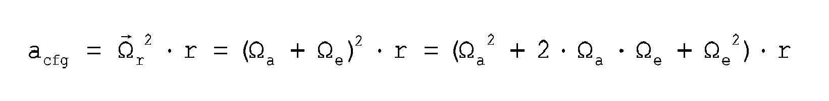
substrate 2, with respect to which the drivingmass 3 oscillates, rotates at the external angular velocity


- The three terms that constitute the expression of the centrifugal acceleration acfg are
Ω a 2·r - relative acceleration of the mass in rotation with respect to the reference system OXYZ;
Ω e 2·r - drag acceleration of the reference system OXYZ with respect to the inertial system O'X'Y'Z';
2 · Ωa · Ωe · r - Coriolis acceleration; in fact, said term can be re-written as 2 · Ωe · (Ωa · r), where (Ωa · r) = va, i.e., as the result of thevector product 
- The same result may be reached by re-writing, for the system described, the general law of composition of accelerations. As is known, given two reference systems, namely, an absolute system O'X'Y'Z' and a relative system OXYZ, the following expression applies:


where θa is the angle of rotation of the entire structure with respect to the reference system OXYZ; the term


- The terms that represent the tangential accelerations do not have any effect on the dynamics of the sensing masses with respect to the driving mass, in so far as the sensing masses can move only in the radial direction. Consequently, the general expression is equivalent to:

- Using a purposely provided read circuit, (for example as described in the patent application
EP 04425600.6 term 2 · Ωa · Ωe, which, once demodulated, is found to be equal to 2 · Ωe, and hence proportional to the external angular velocity Ωe alone, the value of which is to be determined. The other terms (with the fact that they are raised to the second power) can be easily filtered downstream of the demodulator (in so far as they have twice the original frequency), and for this reason they do not cause any significant disturbance at output. What has been described above has been verified by the applicant with a MATLAB "simulink" model. In conclusion, themicroelectromechanical sensor structure 1 modulates the Coriolis acceleration, which, as a result of the way in which the driving dynamics is implemented, has the same direction as the centrifugal acceleration. - As regards the spurious accelerations along the second axis y (but similar considerations apply in the case of detection along the first axis x), they are automatically rejected in so far as reading is performed in a differential way. In fact, whereas the Coriolis useful signal tends to unbalance the
second sensing masses term 2 · Ωa · Ωe · r the vector r has opposite directions), the spurious angular accelerations determine contributions having the same sign. By subtracting the two acceleration signals generated by the two acceleration sensors from one another, it is possible to measure the Coriolis contribution and to reject the spurious acceleration along the second axis y. - As regards the spurious angular accelerations along the axis z, these entail a tangential acceleration that does not cause any disturbance to detection along the second axis y.
- If, instead, an angular acceleration about the first axis x or the second axis y is applied to the system, the driving
mass 3 twists slightly because theelastic anchorage elements 8 at the centre of the structure rigidly oppose bending of the driving mass out of the plane xy. For small rotations along the axis x or y, this entails only ranges of displacement along the axis z for the accelerometer and spurious signals, which again can be intrinsically rejected through the differential reading by the sensor in the plane xy. - As regards the spurious signals deriving from the rotary driving motion about the orthogonal axis z, reference may be made to Figure 12, where it is assumed that both the driving angular velocity


elements 28 are rigid in said direction, the sensor is able to reject said undesirable components of velocity. - In the case of an external angular velocity that lies in the plane of the sensor xy, the components of the driving velocity

elements 28, at least to a first approximation, do not enable any significant out-of-plane displacements. Consequently, the sensor is able to reject also angular velocities that are not directed along the z axis. - A fifth embodiment of the present invention envisages a triaxial sensor structure (in particular a gyroscope), which is obtained by combining the structures described previously.
- In detail (see Figure 13), the
microelectromechanical sensor structure 1 comprises in this case the four pairs offirst sensing masses 16a-16h, for detecting, as described previously, angular velocities corresponding to rotations about a first axis of detection and a second axis of detection (the first and the second axes x, y), and also the pair ofsecond sensing masses second sensing masses - As shown in Figure 14, in order to make the structure altogether symmetrical with respect to the centre O, it is moreover possible to provide a second pair of
second sensing masses openings 26c, 26d, aligned in a second radial direction orthogonal to the first radial direction of alignment of the first pair ofsecond sensing masses - Furthermore, according to what is described, for example, in
EP1617178 or in the patent application No.EP 04425957.0 - As illustrated schematically in Figure 15, the
microelectromechanical sensor structure 1 comprises in this case afirst insulation region 34a and asecond insulation region 34b, which are for example made of silicon oxide, are symmetrical with respect to the centre O, and surround, respectively, a first half and a second half of the first and second sensing masses (in the case represented in the figure, each surrounds four of the first sensing masses and two of the second sensing masses). The first andsecond insulation regions empty space 6, and do not have any points of contact or intersection. In particular, given that both the driving mass and the sensing masses are formed in one and the same structural layer (epitaxial or pseudo-epitaxial layer), the insulation regions extend in a direction transverse to the plane of the sensor xy throughout the thickness of the drivingmass 3, and are closed at the top and at the bottom by plugs, which guarantee, on the one hand, the desired electrical insulation and, on the other, protection of the insulation during manufacturing operations, in particular during a trench etch (deep reactive ion-etching or DRIE of the epitaxial silicon) for definition of the structure, and the etch for removal of sacrificial layers. - The portions of the driving
mass 3 that lie within theinsulation regions detection portions insulation regions portion 3c, forms part of a driving structure (also forming part of which are, amongst other elements, the driven arms 10) and is biased at a driving voltage. In particular, the detection voltage and the driving voltage are applied, respectively, via afirst electrode 35a and asecond electrode 35b, which are insulated from one another, are set in a position corresponding to theanchorage 7, and are each fixed to twoelastic anchorage elements 8, which connect them to the detection and driving portions, respectively, of the drivingmass 3. Notwithstanding the open shape of the rings of theinsulation regions - According to a further aspect of the present invention, the
microelectromechanical sensor structure 1 may be used alternatively as gyroscope (whether uniaxial, biaxial, or triaxial) and as accelerometer (whether uniaxial, biaxial, or triaxial), by simply modifying theelectrical connections 24 between the detection capacitors, and particularly between the first andsecond electrodes electrical connections 24 are not established in the design stage, but can be modified by the purposely provided read circuit, for example by using controlled switches. - By way of example, Figures 16a-16b show the scheme of connections of the detection capacitors associated to one pair of first and second sensing masses (for example, the second pair of
first sensing masses second sensing masses first switch element 36 and asecond switch element 37, which connect, respectively, thefirst electrodes 22 and thesecond electrodes 23 to one another; and athird switch element 38 and afourth switch element 39, which connect a respectivefirst electrode 22 of a sensing mass and a respectivesecond electrode 23 of a different sensing mass of the same pair, to one another. - In detail, the read circuit controls the gyroscope operating mode of the sensor structure, simply by setting the third and
fourth switch elements second switch elements second switch elements fourth switch elements - The advantages of the microelectromechanical sensor structure according to the invention are clear from the foregoing description.
- In any case, it is underlined again that it is possible to provide uniaxial, biaxial and in particular triaxial gyroscopes of compact dimensions, given the presence of a single driving mass that encloses in its overall dimensions the sensing masses designed for detection. The rotary motion of the driving mass enables two components of driving velocity, orthogonal to one another in the plane of the sensor, to be automatically obtained, and hence effective implementation of a biaxial detection. Furthermore, the presence of the sensing masses free to move in a radial direction, responsive to the Coriolis force having the same direction as the centrifugal acceleration, enables implementation of a triaxial detection.
- The presence of a single central anchorage for the driving mass enables reduction of the thermomechanical stresses (in a per-se known way - see, for example,
EP1083144 filed in the name of the present applicant, which relates to a microelectromechanical accelerometer), in addition to allowing the aforesaid rotary motion. - The drive and detection dynamics are clearly decoupled from one another, thanks to the particular geometry and arrangement of the elastic supporting and anchoring elements.
- The described structure enables a good rejection of spurious linear and angular accelerations and angular cross-velocities for any direction of detection to be obtained.
- In addition, it is possible to switch the mode of operation of the microelectromechanical structure between an accelerometer mode and a gyroscope mode by simply modifying the connections between the detection capacitors (an operation that can be carried out by a purposely provided read circuit). In this connection, Figure 17 illustrates a
sensor device 40 comprising: themicroelectromechanical sensor structure 1; a drivingcircuit 41, connected to the drivingassembly 4 for imparting the rotary driving motion on the drivingmass 3; and aread circuit 42, connected to thedetection electrodes - Finally, it is clear that modifications and variations can be made to what is described and illustrated herein, without thereby departing from the scope of the present invention, as defined in the annexed claims.
- In particular, the driving
mass 3 can have a shape different from the circular one, for example any closed polygonal shape. Furthermore, even though this may not be advantageous, said shape may not have a perfect radial symmetry (or in general any other type of symmetry). - In a per-se known manner, the displacement of the sensing masses can be detected with a different technique other than the capacitive one, for example, by detecting a magnetic force.
- It is also evident that yet other structures different from the ones shown can be obtained, by appropriately combining pairs of first and second sensing masses; for example, a biaxial gyroscope with axes of detection x-z, or y-z can be obtained.
- Furthermore, the torsional moment for causing the driving mass to oscillate with rotary motion can be generated in a different manner, for example by means of parallel-plate electrodes, or else magnetic actuation.
- Finally, the microelectromechanical structure, in its simplest embodiment, can comprise a single (first or second) sensing mass, with the disadvantage of not being able to reject linear accelerations in the direction of detection.
Claims (17)
- An integrated microelectromechanical structure (1), characterized by comprising: a driving mass (3), which is designed to be moved with a rotary motion about an axis of rotation (z) and is anchored via elastic anchorage elements (8) to an anchorage (7) arranged along said axis of rotation (z), at least one first opening (9a) being provided within said driving mass (3); and a first sensing mass of a first type (16a), arranged inside said first opening (9a) and connected to said driving mass (3) via first elastic supporting elements (20) in such a manner as to perform a first detection movement in the presence of a first external stress; said first elastic supporting elements (20) and said elastic anchorage elements (8) being configured in such a manner that said first sensing mass of a first type (16a) is fixed to said driving mass (3) in said rotary driving motion, and is substantially decoupled from said driving mass (3) in said first detection movement.
- The structure according to claim 1, wherein said driving mass (3) extends substantially in a plane (xy) and said axis of rotation (z) is perpendicular to said plane (xy); said anchorage (7) being arranged substantially at the centre (O) of said driving mass (3).
- The structure according to claim 2, further comprising at least one first sensing mass of a second type (25a), arranged inside a second opening (26a) provided within said driving mass (3) and connected to said driving mass via second elastic supporting elements (28) in such a manner as to perform a second detection movement in the presence of a second external stress; said first detection movement being a rotational movement about an axis lying in said plane (xy), and said second detection movement being a linear movement along an axis lying in said plane (xy).
- The structure according to claim 3, wherein said second external stress is a Coriolis force (Fc) acting in a first radial direction (r), and said linear movement is directed movement said first radial direction (r).
- The structure according to any one of the preceding claims, wherein said driving mass (3) extends substantially in a plane (xy), further comprising: a second sensing mass of a first type (16b), which is aligned to said first sensing mass of a first type (16a) along a first axis of detection (x) lying in said plane (xy) and is arranged in a respective opening (9b) provided within said driving mass (3), said first and second sensing masses of a first type (16a, 16b) being enclosed in the overall dimensions of said driving mass (3) in said plane (xy); and detection means (22, 23) associated to each of said first and second sensing masses of a first type (16a, 16b) for detecting said first detection movement; said first detection movement being a rotational movement about an axis lying in said plane (xy) and perpendicular to said first axis of detection (x).
- The structure according to claim 5, comprising connection means (24, 36-39) configured to electrically connect the detection means (22, 23) associated to said first sensing mass of a first type (16a) to the detection means associated to said second sensing mass of a first type (16b); said connection means (24, 36-39) being configured to implement, in given operating conditions, a differential detection scheme.
- The structure according to claim 6, wherein said connection means (24, 36-39) are further configured to switch a mode of operation of said microelectromechanical structure (1) between a gyroscope mode and an accelerometer mode.
- The structure according to claim 6 or 7, wherein said detection means comprise a first detection electrode (22) and a second detection electrode (23), which are set facing each of said first and second sensing masses of a first type (16a, 16b), and said connection means comprise: a first switch element and a second switch element (36, 37) which connect to one another, respectively, said first detection electrodes (22) and said second detection electrodes (23) facing said sensing masses of a first type; and a third switch and a fourth switch (38, 39) which connect said first and second electrode (22, 23) facing said first sensing mass of a first type (16a) respectively to said second and first electrode (23, 22) facing said second sensing mass of a first type (16b); wherein said first and second switch elements (36, 37) are configured in an open condition and said third and fourth switch elements (38, 39) are configured in a closed condition for implementing said gyroscope mode, and said first and second switch elements (36, 37) are configured in a closed condition and said third and fourth switch elements (38, 39) are configured in an open condition for implementing said accelerometer mode.
- The structure according to any one of the preceding claims, further comprising: a second sensing mass of a first type (16b) forming with said first sensing mass of a first type (16a) a first pair of sensing masses of a first type, aligned along a first axis of detection (x) lying in said plane (xy) on opposite sides with respect to said anchorage (7); and a second pair of sensing masses of a first type (16c, 16d) aligned along a second axis of detection (y) lying in said plane (xy) and orthogonal to said first axis of detection (x), on opposite sides of said anchorage.
- The structure according to claim 9, further comprising a pair of sensing masses of a second type (25a, 25b) aligned in a first radial direction (r), on opposite sides of said anchorage (7); said sensing masses of a second type (25a, 25b) being connected to said driving mass (3) via respective second elastic supporting elements (28) in such a manner as to perform a second detection movement in the presence of a second external stress.
- The structure according to claim 10 defining a triaxial gyroscope, wherein said first and second pairs of sensing masses of a first type (16a-16b, 16c-16d) are configured to detect, respectively, a first external angular velocity and a second external angular velocity


- The structure according to any one of the preceding claims, further comprising: a second sensing mass of a first type (16b) forming with said first sensing mass of a first type (16a) a first pair of sensing masses of a first type, which are symmetrical to one another with respect to said anchorage (7) and are set on opposite sides of a first axis of detection (x) lying in said plane (xy); a second pair of sensing masses of a first type (16c, 16d), which are symmetrical with respect to said anchorage (7) and are set on opposite sides of a second axis of detection (y) lying in said plane (xy) and orthogonal to said first axis of detection (x); and a further pair of sensing masses of a first type (16e-16f, 16g-16h) for each of said first and second axes of detection (x, y), which are symmetrical with respect to said anchorage (7) and are set on opposite sides of a respective one of said first and second axes of detection (x, y) with respect to a respective one of said first and second pairs of sensing masses of a first type; corresponding sensing masses of pairs associated to one and the same axis of detection being set facing one another with respect to said respective axis of detection, and having first elastic supporting elements (20) staggered along said respective axis of detection.
- The structure according to any one of claims 9-12, wherein said driving mass (3) defines at the centre an empty space (6); further comprising an electrical-insulation region (34a, 34b), which electrically insulates a driving portion (3c) from a detection portion (3a, 3b) of said driving mass (3), which are biased, in use, at different voltages; said electrical-insulation region (34a, 34b) comprising a first ring (34a) surrounding a part of said sensing masses and a second ring (34b) surrounding another part of said sensing masses, said first and second rings (34a, 34b) being open at said empty space (6) and defining internally said detection portion (3a, 3b) and externally said driving portion (3c).
- The structure according to any one of the preceding claims, wherein said driving mass (3) has in said plane (xy) a circular geometry, having a first axis of symmetry and a second axis of symmetry (A, B) and defining at the centre an empty space (6) with a centre (O) in a position corresponding to said anchorage (7); said elastic anchorage elements (8) extending within said empty space (6).
- A sensor device (40) comprising a microelectromechanical structure (1), according to any one of the preceding claims.
- The sensor device according to claim 15, further comprising a read stage (42) configured to switch a mode of operation of said microelectromechanical structure (1) between a gyroscope mode and an accelerometer mode.
- The sensor device according to claim 16, wherein said microelectromechanical structure (1) comprises detection means (22, 23) for detecting said first detection movement and connection means (24, 36-39) for electrical connection of said detection means (22, 23); and said read stage (42) is configured to interact with said connection means for switching said mode of operation of said microelectromechanical structure (1).
Priority Applications (3)
| Application Number | Priority Date | Filing Date | Title |
|---|---|---|---|
| EP06425163.0A EP1832841B1 (en) | 2006-03-10 | 2006-03-10 | Microelectromechanical integrated sensor structure with rotary driving motion |
| JP2007060949A JP5319891B2 (en) | 2006-03-10 | 2007-03-09 | Micro-electromechanical integrated sensor structure using rotational drive motion |
| US11/684,243 US7694563B2 (en) | 2006-03-10 | 2007-03-09 | Microelectromechanical integrated sensor structure with rotary driving motion |
Applications Claiming Priority (1)
| Application Number | Priority Date | Filing Date | Title |
|---|---|---|---|
| EP06425163.0A EP1832841B1 (en) | 2006-03-10 | 2006-03-10 | Microelectromechanical integrated sensor structure with rotary driving motion |
Publications (2)
| Publication Number | Publication Date |
|---|---|
| EP1832841A1 true EP1832841A1 (en) | 2007-09-12 |
| EP1832841B1 EP1832841B1 (en) | 2015-12-30 |
Family
ID=36779030
Family Applications (1)
| Application Number | Title | Priority Date | Filing Date |
|---|---|---|---|
| EP06425163.0A Active EP1832841B1 (en) | 2006-03-10 | 2006-03-10 | Microelectromechanical integrated sensor structure with rotary driving motion |
Country Status (3)
| Country | Link |
|---|---|
| US (1) | US7694563B2 (en) |
| EP (1) | EP1832841B1 (en) |
| JP (1) | JP5319891B2 (en) |
Cited By (47)
| Publication number | Priority date | Publication date | Assignee | Title |
|---|---|---|---|---|
| WO2009156485A1 (en) * | 2008-06-27 | 2009-12-30 | Sensordynamics Ag | Microgyroscope |
| FR2937721A1 (en) * | 2008-10-29 | 2010-04-30 | Bosch Gmbh Robert | METHOD FOR MANAGING A SENSOR DEVICE AND SENSOR DEVICE FOR ITS IMPLEMENTATION |
| ITTO20080876A1 (en) * | 2008-11-26 | 2010-05-27 | St Microelectronics Srl | MICROELETTROMECHANICAL GYROSCOPE WITH ROTARY DRIVE MOVEMENT AND IMPROVED ELECTRICAL CHARACTERISTICS |
| ITTO20080877A1 (en) * | 2008-11-26 | 2010-05-27 | St Microelectronics Srl | MONO OR BIASSIAL MICROELECTROMECHANICAL GYROSCOPE WITH INCREASED SENSITIVITY TO THE ANGULAR SPEED DETECTION |
| ITTO20080981A1 (en) * | 2008-12-23 | 2010-06-24 | St Microelectronics Srl | MICROELETTROMECHANICAL GYROSCOPE WITH IMPROVED REJECTION OF ACCELERATION DISORDERS |
| CN101788567A (en) * | 2008-11-26 | 2010-07-28 | 意法半导体股份有限公司 | The detection side is to the multiaxis MEMS gyroscope and the sensing circuit thereof that tilt with axis of reference |
| DE102009001244A1 (en) * | 2009-02-27 | 2010-09-02 | Sensordynamics Ag | Micro gyroscope for determining rotational movements about an x, y or z axis |
| DE102009001922A1 (en) * | 2009-03-26 | 2010-09-30 | Sensordynamics Ag | Micro-gyroscope for determining rotational movements about three mutually perpendicular spatial axes x, y and z |
| WO2010136379A1 (en) * | 2009-05-27 | 2010-12-02 | Sensordynamics Ag | Microgyroscope for determining rotational motions about at least one of three perpendicular spatial axes |
| DE102010040516A1 (en) | 2009-09-09 | 2011-03-10 | Continental Teves Ag & Co. Ohg | Double-axial, shock-resistant rotation rate sensor with interwoven, linearly oscillating seismic elements |
| CN102052920A (en) * | 2010-11-23 | 2011-05-11 | 孙博华 | Wheeled single-structure three-axis micromechanical gyroscope |
| US8042396B2 (en) | 2007-09-11 | 2011-10-25 | Stmicroelectronics S.R.L. | Microelectromechanical sensor with improved mechanical decoupling of sensing and driving modes |
| WO2011136971A1 (en) * | 2010-04-30 | 2011-11-03 | Qualcomm Mems Technologies, Inc. | Micromachined piezoelectric x-axis gyroscope |
| CN102334010A (en) * | 2009-02-27 | 2012-01-25 | 感应动力股份公司 | Mems gyroscope for detecting rotational motions about an x-, y-, and/or z-axis |
| WO2012037540A2 (en) | 2010-09-18 | 2012-03-22 | Fairchild Semiconductor Corporation | Micromachined monolithic 3-axis gyroscope with single drive |
| WO2012131682A1 (en) * | 2011-03-31 | 2012-10-04 | Ramot At Tel-Aviv University Ltd. | Compliant structures with time-varying moment of inertia |
| US8342025B2 (en) | 2009-05-11 | 2013-01-01 | Stmicroelectronics S.R.L. | Microelectromechanical structure with enhanced rejection of acceleration noise |
| US8459093B2 (en) | 2009-12-21 | 2013-06-11 | Stmicroelectronics S.R.L. | Microelectromechanical gyroscope with continuous self-test function |
| US8459110B2 (en) | 2009-12-24 | 2013-06-11 | Stmicroelectronics S.R.L. | Integrated microelectromechanical gyroscope with improved driving structure |
| EP2607849A1 (en) * | 2011-12-22 | 2013-06-26 | Tronics Microsystems S.A. | Multiaxial micro-electronic inertial sensor |
| US8474317B2 (en) | 2009-12-21 | 2013-07-02 | Stmicroelectronics S.R.L. | Microelectromechanical device having an oscillating mass, and method for controlling a microelectromechanical device having an oscillating mass |
| DE102012219511A1 (en) | 2012-10-25 | 2014-04-30 | Robert Bosch Gmbh | Micromechanical structure |
| US8739626B2 (en) | 2009-08-04 | 2014-06-03 | Fairchild Semiconductor Corporation | Micromachined inertial sensor devices |
| US8813564B2 (en) | 2010-09-18 | 2014-08-26 | Fairchild Semiconductor Corporation | MEMS multi-axis gyroscope with central suspension and gimbal structure |
| US8978475B2 (en) | 2012-02-01 | 2015-03-17 | Fairchild Semiconductor Corporation | MEMS proof mass with split z-axis portions |
| US9006846B2 (en) | 2010-09-20 | 2015-04-14 | Fairchild Semiconductor Corporation | Through silicon via with reduced shunt capacitance |
| US9052194B2 (en) | 2009-09-11 | 2015-06-09 | Invensense, Inc. | Extension-mode angular velocity sensor |
| US9062972B2 (en) | 2012-01-31 | 2015-06-23 | Fairchild Semiconductor Corporation | MEMS multi-axis accelerometer electrode structure |
| US9069006B2 (en) | 2012-04-05 | 2015-06-30 | Fairchild Semiconductor Corporation | Self test of MEMS gyroscope with ASICs integrated capacitors |
| US9094027B2 (en) | 2012-04-12 | 2015-07-28 | Fairchild Semiconductor Corporation | Micro-electro-mechanical-system (MEMS) driver |
| US9095072B2 (en) | 2010-09-18 | 2015-07-28 | Fairchild Semiconductor Corporation | Multi-die MEMS package |
| US9097524B2 (en) | 2009-09-11 | 2015-08-04 | Invensense, Inc. | MEMS device with improved spring system |
| US9156673B2 (en) | 2010-09-18 | 2015-10-13 | Fairchild Semiconductor Corporation | Packaging to reduce stress on microelectromechanical systems |
| US9234755B2 (en) | 2010-02-15 | 2016-01-12 | Stmicroelectronics S.R.L. | Microelectromechanical gyroscope with calibrated synchronization of actuation and method for actuating a microelectromechanical gyroscope |
| US9278846B2 (en) | 2010-09-18 | 2016-03-08 | Fairchild Semiconductor Corporation | Micromachined monolithic 6-axis inertial sensor |
| US9352961B2 (en) | 2010-09-18 | 2016-05-31 | Fairchild Semiconductor Corporation | Flexure bearing to reduce quadrature for resonating micromachined devices |
| US9425328B2 (en) | 2012-09-12 | 2016-08-23 | Fairchild Semiconductor Corporation | Through silicon via including multi-material fill |
| US9444404B2 (en) | 2012-04-05 | 2016-09-13 | Fairchild Semiconductor Corporation | MEMS device front-end charge amplifier |
| US9488693B2 (en) | 2012-04-04 | 2016-11-08 | Fairchild Semiconductor Corporation | Self test of MEMS accelerometer with ASICS integrated capacitors |
| US9618361B2 (en) | 2012-04-05 | 2017-04-11 | Fairchild Semiconductor Corporation | MEMS device automatic-gain control loop for mechanical amplitude drive |
| US9625272B2 (en) | 2012-04-12 | 2017-04-18 | Fairchild Semiconductor Corporation | MEMS quadrature cancellation and signal demodulation |
| US10060757B2 (en) | 2012-04-05 | 2018-08-28 | Fairchild Semiconductor Corporation | MEMS device quadrature shift cancellation |
| US10065851B2 (en) | 2010-09-20 | 2018-09-04 | Fairchild Semiconductor Corporation | Microelectromechanical pressure sensor including reference capacitor |
| US10598690B2 (en) | 2011-09-12 | 2020-03-24 | Stmicroelectronics S.R.L. | Microelectromechanical device incorporating a gyroscope and an accelerometer |
| US10697994B2 (en) | 2017-02-22 | 2020-06-30 | Semiconductor Components Industries, Llc | Accelerometer techniques to compensate package stress |
| DE102021200483A1 (en) | 2021-01-20 | 2022-07-21 | Robert Bosch Gesellschaft mit beschränkter Haftung | Triaxial yaw rate sensor with a substrate and a double rotor |
| EP4148383A3 (en) * | 2021-08-18 | 2023-05-24 | Honeywell International Inc. | Rotation measurement system using coriolis and euler forces |
Families Citing this family (64)
| Publication number | Priority date | Publication date | Assignee | Title |
|---|---|---|---|---|
| DE102007046306B4 (en) | 2007-09-27 | 2021-10-14 | Robert Bosch Gmbh | Accelerometer |
| US20110088469A1 (en) * | 2007-11-08 | 2011-04-21 | Reinhard Neul | Rotation-rate sensor having two sensitive axes |
| DE102007054505B4 (en) | 2007-11-15 | 2016-12-22 | Robert Bosch Gmbh | Yaw rate sensor |
| JP4929489B2 (en) * | 2007-12-19 | 2012-05-09 | 株式会社村田製作所 | Angular velocity sensor |
| US8082788B1 (en) * | 2007-12-20 | 2011-12-27 | Advanced Numicro Systems, Inc. | MEMS load cell and strain sensor |
| JP5247182B2 (en) * | 2008-02-19 | 2013-07-24 | キヤノン株式会社 | Angular velocity sensor |
| DE102009002066A1 (en) | 2009-03-31 | 2010-10-07 | Sensordynamics Ag | Method for detecting accelerations and yaw rates and MEMS sensor |
| JP2012528335A (en) * | 2009-05-27 | 2012-11-12 | キング アブドゥーラ ユニバーシティ オブ サイエンス アンド テクノロジー | MEMS mass-spring-damper system using out-of-plane suspension system |
| IT1394898B1 (en) * | 2009-06-03 | 2012-07-20 | St Microelectronics Rousset | MICROELETTROMECHANICAL GYROSCOPE WITH POSITION CONTROL AND METHOD FOR THE CONTROL OF A MICROELECTRANOMANICAL GYROSCOPE |
| DE102009027897B4 (en) * | 2009-07-21 | 2023-07-20 | Robert Bosch Gmbh | Micromechanical rotation rate sensor |
| DE102010028005A1 (en) | 2010-04-20 | 2011-10-20 | Sensordynamics Ag | Micro gyroscope for detecting movements |
| WO2011158348A1 (en) * | 2010-06-16 | 2011-12-22 | トヨタ自動車株式会社 | Composite sensor |
| JP5652112B2 (en) * | 2010-10-18 | 2015-01-14 | セイコーエプソン株式会社 | Physical quantity sensor and electronic equipment |
| JP5652117B2 (en) * | 2010-10-21 | 2015-01-14 | セイコーエプソン株式会社 | Physical quantity sensor and electronic equipment |
| DE102010062095A1 (en) * | 2010-11-29 | 2012-05-31 | Robert Bosch Gmbh | Rotation rate sensor and method for operating a rotation rate sensor |
| ITTO20110687A1 (en) | 2011-07-28 | 2013-01-29 | St Microelectronics Srl | MICROELETTROMECHANICAL SENSOR WITH DIFFERENTIAL PERFORMANCE AND METHOD OF CONTROL OF A MICROELECTRANCANICAL SENSOR |
| US9714842B2 (en) * | 2011-09-16 | 2017-07-25 | Invensense, Inc. | Gyroscope self test by applying rotation on coriolis sense mass |
| US8833162B2 (en) * | 2011-09-16 | 2014-09-16 | Invensense, Inc. | Micromachined gyroscope including a guided mass system |
| US9863769B2 (en) | 2011-09-16 | 2018-01-09 | Invensense, Inc. | MEMS sensor with decoupled drive system |
| US10914584B2 (en) | 2011-09-16 | 2021-02-09 | Invensense, Inc. | Drive and sense balanced, semi-coupled 3-axis gyroscope |
| US9170107B2 (en) * | 2011-09-16 | 2015-10-27 | Invensense, Inc. | Micromachined gyroscope including a guided mass system |
| US8448513B2 (en) | 2011-10-05 | 2013-05-28 | Freescale Semiconductor, Inc. | Rotary disk gyroscope |
| DE102011057081A1 (en) * | 2011-12-28 | 2013-07-04 | Maxim Integrated Products, Inc. | Micro rotation rate sensor and method for operating a micro yaw rate sensor |
| US9759563B2 (en) * | 2012-01-31 | 2017-09-12 | Nxp Usa, Inc. | Vibration robust x-axis ring gyro transducer |
| GB201205014D0 (en) * | 2012-03-22 | 2012-05-09 | Atlantic Inertial Systems Ltd | Vibratory ring structure |
| JP6061064B2 (en) * | 2012-05-14 | 2017-01-18 | セイコーエプソン株式会社 | Gyro sensor and electronic equipment |
| US9194704B2 (en) | 2013-03-13 | 2015-11-24 | Freescale Semiconductor, Inc. | Angular rate sensor having multiple axis sensing capability |
| US9448071B2 (en) * | 2013-03-13 | 2016-09-20 | Stmicroelectronics S.R.L. | Microelectromechanical device having an oscillating mass and a forcing stage, and method of controlling a microelectromechanical device |
| WO2015042700A1 (en) | 2013-09-24 | 2015-04-02 | Motion Engine Inc. | Mems components and method of wafer-level manufacturing thereof |
| EP3019442A4 (en) | 2013-07-08 | 2017-01-25 | Motion Engine Inc. | Mems device and method of manufacturing |
| KR101454122B1 (en) * | 2013-07-31 | 2014-10-22 | 삼성전기주식회사 | Sensing Module and Angular Velocity Sensor having the same |
| WO2015013828A1 (en) | 2013-08-02 | 2015-02-05 | Motion Engine Inc. | Mems motion sensor and method of manufacturing |
| WO2015045621A1 (en) * | 2013-09-26 | 2015-04-02 | 株式会社村田製作所 | Angular velocity detection element |
| US9404747B2 (en) | 2013-10-30 | 2016-08-02 | Stmicroelectroncs S.R.L. | Microelectromechanical gyroscope with compensation of quadrature error drift |
| JP6248576B2 (en) * | 2013-11-25 | 2017-12-20 | セイコーエプソン株式会社 | Functional element, electronic device, and moving object |
| TWI538096B (en) | 2013-12-31 | 2016-06-11 | 財團法人工業技術研究院 | Mems apparatus with pn-junction |
| JP6590812B2 (en) | 2014-01-09 | 2019-10-16 | モーション・エンジン・インコーポレーテッド | Integrated MEMS system |
| US9958271B2 (en) | 2014-01-21 | 2018-05-01 | Invensense, Inc. | Configuration to reduce non-linear motion |
| CN103822620A (en) * | 2014-02-20 | 2014-05-28 | 上海交通大学 | Electrostatic drive type parameter excited micromechanic solid fluctuation disc gyroscope |
| JP2015184009A (en) | 2014-03-20 | 2015-10-22 | セイコーエプソン株式会社 | Vibration element, electronic apparatus, and mobile entity |
| WO2015154173A1 (en) | 2014-04-10 | 2015-10-15 | Motion Engine Inc. | Mems pressure sensor |
| CN105043370B (en) | 2014-04-29 | 2019-01-22 | 财团法人工业技术研究院 | Micro-motor device with fulcrum element |
| EP4166902A1 (en) * | 2014-05-21 | 2023-04-19 | InvenSense, Inc. | Mems sensor with decoupled drive system |
| US11674803B2 (en) | 2014-06-02 | 2023-06-13 | Motion Engine, Inc. | Multi-mass MEMS motion sensor |
| US10330471B2 (en) * | 2014-11-27 | 2019-06-25 | Goertek, Inc. | Triaxial micro-electromechanical gyroscope |
| WO2016090467A1 (en) | 2014-12-09 | 2016-06-16 | Motion Engine Inc. | 3d mems magnetometer and associated methods |
| US10407299B2 (en) | 2015-01-15 | 2019-09-10 | Motion Engine Inc. | 3D MEMS device with hermetic cavity |
| DE102015207856A1 (en) * | 2015-04-29 | 2016-11-17 | Robert Bosch Gmbh | Rate of rotation sensor and method |
| CN107636473B (en) | 2015-05-20 | 2020-09-01 | 卢米达因科技公司 | Extracting inertial information from non-linear periodic signals |
| DE102015117094B4 (en) | 2015-10-07 | 2020-04-23 | Tdk Electronics Ag | MEMS rotation rate sensor |
| JP6149910B2 (en) * | 2015-10-08 | 2017-06-21 | セイコーエプソン株式会社 | Physical quantity sensor and electronic equipment |
| CN106813816B (en) * | 2015-11-28 | 2020-07-10 | 陈剑 | Load balance measurement |
| ITUA20161498A1 (en) * | 2016-03-09 | 2017-09-09 | St Microelectronics Srl | MICROMECHANICAL DETECTION STRUCTURE OF A MEMS SENSOR DEVICE, IN PARTICULAR OF A MEMS GYRO, WITH IMPROVED DRIVE CHARACTERISTICS |
| DE102016104551A1 (en) * | 2016-03-11 | 2017-09-14 | Krohne Ag | Method for equipping a Coriolis mass flowmeter with electrical connections |
| ITUA20162172A1 (en) * | 2016-03-31 | 2017-10-01 | St Microelectronics Srl | ACCELEROMETRIC SENSOR MADE IN MEMS TECHNOLOGY WITH HIGH ACCURACY AND REDUCED SENSITIVITY TOWARDS TEMPERATURE AND AGING |
| US10234477B2 (en) | 2016-07-27 | 2019-03-19 | Google Llc | Composite vibratory in-plane accelerometer |
| JP6849042B2 (en) | 2018-12-19 | 2021-03-24 | 株式会社村田製作所 | Vibration-resistant multi-axis gyroscope |
| EP3671116B1 (en) * | 2018-12-19 | 2021-11-17 | Murata Manufacturing Co., Ltd. | Synchronized multi-axis gyroscope |
| JP6879391B2 (en) * | 2019-02-15 | 2021-06-02 | 株式会社村田製作所 | Multi-axis gyroscope with sync frame |
| EP3696503B1 (en) * | 2019-02-15 | 2022-10-26 | Murata Manufacturing Co., Ltd. | Vibration-robust multiaxis gyroscope |
| US11060866B2 (en) * | 2019-02-15 | 2021-07-13 | Murata Manufacturing Co., Ltd. | Balanced multiaxis gyroscope |
| JP7188311B2 (en) * | 2019-07-31 | 2022-12-13 | セイコーエプソン株式会社 | Gyro sensors, electronic devices, and mobile objects |
| DE102020205369A1 (en) * | 2020-04-28 | 2021-10-28 | Robert Bosch Gesellschaft mit beschränkter Haftung | Micromechanical component for a yaw rate sensor and a corresponding manufacturing process |
| CN113091722A (en) * | 2021-04-02 | 2021-07-09 | 瑞声开泰科技(武汉)有限公司 | Three-axis micromechanical gyroscope and angular velocity measuring method |
Citations (6)
| Publication number | Priority date | Publication date | Assignee | Title |
|---|---|---|---|---|
| DE19641284C1 (en) * | 1996-10-07 | 1998-05-20 | Inst Mikro Und Informationstec | Rotation rate sensor with decoupled orthogonal primary and secondary vibrations |
| EP0971208A2 (en) * | 1998-07-10 | 2000-01-12 | Murata Manufacturing Co., Ltd. | Angular velocity sensor |
| WO2000029855A1 (en) * | 1998-10-14 | 2000-05-25 | Irvine Sensors Corporation | Multi-element micro-gyro |
| US6308567B1 (en) * | 1998-12-10 | 2001-10-30 | Denso Corporation | Angular velocity sensor |
| US20020189352A1 (en) * | 2001-06-19 | 2002-12-19 | Reeds John William | Mems sensor with single central anchor and motion-limiting connection geometry |
| DE102004017480A1 (en) * | 2004-04-08 | 2005-10-27 | Fraunhofer-Gesellschaft zur Förderung der angewandten Forschung e.V. | Rotary rotation rate sensor with mechanically decoupled vibration modes |
Family Cites Families (25)
| Publication number | Priority date | Publication date | Assignee | Title |
|---|---|---|---|---|
| DE19523895A1 (en) | 1995-06-30 | 1997-01-02 | Bosch Gmbh Robert | Acceleration sensor |
| DE19617666B4 (en) * | 1996-05-03 | 2006-04-20 | Robert Bosch Gmbh | Micromechanical rotation rate sensor |
| GB9621873D0 (en) * | 1996-10-21 | 1996-12-11 | British Tech Group | A solid state,multi-axis gyroscope |
| JP3882973B2 (en) * | 1998-06-22 | 2007-02-21 | アイシン精機株式会社 | Angular velocity sensor |
| DE19850066B4 (en) * | 1998-10-30 | 2008-05-21 | Robert Bosch Gmbh | Micromechanical tilt sensor |
| US6189381B1 (en) * | 1999-04-26 | 2001-02-20 | Sitek, Inc. | Angular rate sensor made from a structural wafer of single crystal silicon |
| EP1083144B1 (en) | 1999-09-10 | 2008-05-07 | STMicroelectronics S.r.l. | Micro-electromechanical structure insensitive to mechanical stresses. |
| EP1212585B1 (en) * | 1999-09-17 | 2010-08-04 | Kionix, Inc. | Electrically decoupled micromachined gyroscope |
| US6686807B1 (en) * | 1999-11-02 | 2004-02-03 | Eta Sa Fabriques D'ebauches | Time base comprising an integrated micromechanical ring resonator |
| US6374672B1 (en) * | 2000-07-28 | 2002-04-23 | Litton Systems, Inc. | Silicon gyro with integrated driving and sensing structures |
| JP2002296038A (en) * | 2001-03-30 | 2002-10-09 | Mitsubishi Electric Corp | Angular velocity sensor |
| DE60120921T2 (en) | 2001-04-27 | 2007-02-01 | Stmicroelectronics S.R.L., Agrate Brianza | Integrated gyro made of semiconductor material |
| US20020189351A1 (en) | 2001-06-14 | 2002-12-19 | Reeds John W. | Angular rate sensor having a sense element constrained to motion about a single axis and flexibly attached to a rotary drive mass |
| US6715352B2 (en) * | 2001-06-26 | 2004-04-06 | Microsensors, Inc. | Method of designing a flexure system for tuning the modal response of a decoupled micromachined gyroscope and a gyroscoped designed according to the method |
| DE10152254A1 (en) * | 2001-10-20 | 2003-04-30 | Bosch Gmbh Robert | Micromechanical component and corresponding manufacturing method |
| DE60221103T2 (en) | 2002-05-21 | 2008-04-03 | Stmicroelectronics S.R.L., Agrate Brianza | Integrated gyroscope made of semiconductor material with at least one sensitive axis in the sensor plane |
| KR100476562B1 (en) * | 2002-12-24 | 2005-03-17 | 삼성전기주식회사 | Horizontal and tuning fork vibratory micro gyroscope |
| US20040231420A1 (en) * | 2003-02-24 | 2004-11-25 | Huikai Xie | Integrated monolithic tri-axial micromachined accelerometer |
| US6837107B2 (en) * | 2003-04-28 | 2005-01-04 | Analog Devices, Inc. | Micro-machined multi-sensor providing 1-axis of acceleration sensing and 2-axes of angular rate sensing |
| JP2005241500A (en) * | 2004-02-27 | 2005-09-08 | Mitsubishi Electric Corp | Angular velocity sensor |
| JP4654668B2 (en) * | 2004-03-12 | 2011-03-23 | パナソニック電工株式会社 | Gyro sensor and sensor device using the same |
| EP1617178B1 (en) | 2004-07-12 | 2017-04-12 | STMicroelectronics Srl | Micro-electro-mechanical structure having electrically insulated regions and manufacturing process thereof |
| US7100446B1 (en) * | 2004-07-20 | 2006-09-05 | The Regents Of The University Of California | Distributed-mass micromachined gyroscopes operated with drive-mode bandwidth enhancement |
| EP1624286B1 (en) | 2004-08-03 | 2017-10-04 | STMicroelectronics Srl | Micro-electro-mechanical sensor with force feedback loop |
| US8042394B2 (en) * | 2007-09-11 | 2011-10-25 | Stmicroelectronics S.R.L. | High sensitivity microelectromechanical sensor with rotary driving motion |
-
2006
- 2006-03-10 EP EP06425163.0A patent/EP1832841B1/en active Active
-
2007
- 2007-03-09 US US11/684,243 patent/US7694563B2/en active Active
- 2007-03-09 JP JP2007060949A patent/JP5319891B2/en active Active
Patent Citations (6)
| Publication number | Priority date | Publication date | Assignee | Title |
|---|---|---|---|---|
| DE19641284C1 (en) * | 1996-10-07 | 1998-05-20 | Inst Mikro Und Informationstec | Rotation rate sensor with decoupled orthogonal primary and secondary vibrations |
| EP0971208A2 (en) * | 1998-07-10 | 2000-01-12 | Murata Manufacturing Co., Ltd. | Angular velocity sensor |
| WO2000029855A1 (en) * | 1998-10-14 | 2000-05-25 | Irvine Sensors Corporation | Multi-element micro-gyro |
| US6308567B1 (en) * | 1998-12-10 | 2001-10-30 | Denso Corporation | Angular velocity sensor |
| US20020189352A1 (en) * | 2001-06-19 | 2002-12-19 | Reeds John William | Mems sensor with single central anchor and motion-limiting connection geometry |
| DE102004017480A1 (en) * | 2004-04-08 | 2005-10-27 | Fraunhofer-Gesellschaft zur Förderung der angewandten Forschung e.V. | Rotary rotation rate sensor with mechanically decoupled vibration modes |
Cited By (111)
| Publication number | Priority date | Publication date | Assignee | Title |
|---|---|---|---|---|
| US8042396B2 (en) | 2007-09-11 | 2011-10-25 | Stmicroelectronics S.R.L. | Microelectromechanical sensor with improved mechanical decoupling of sensing and driving modes |
| USRE45792E1 (en) | 2007-09-11 | 2015-11-03 | Stmicroelectronics S.R.L. | High sensitivity microelectromechanical sensor with driving motion |
| USRE45855E1 (en) | 2007-09-11 | 2016-01-19 | Stmicroelectronics S.R.L. | Microelectromechanical sensor with improved mechanical decoupling of sensing and driving modes |
| US8429970B2 (en) | 2008-06-27 | 2013-04-30 | Maxim Integrated Products Gmbh | Microgyroscope |
| DE102008002748A1 (en) * | 2008-06-27 | 2009-12-31 | Sensordynamics Ag | Microgyroscope |
| WO2009156485A1 (en) * | 2008-06-27 | 2009-12-30 | Sensordynamics Ag | Microgyroscope |
| CN102077054B (en) * | 2008-06-27 | 2013-05-29 | 玛克西姆综合公司 | Microgyroscope |
| FR2937721A1 (en) * | 2008-10-29 | 2010-04-30 | Bosch Gmbh Robert | METHOD FOR MANAGING A SENSOR DEVICE AND SENSOR DEVICE FOR ITS IMPLEMENTATION |
| EP2192382A1 (en) | 2008-11-26 | 2010-06-02 | STMicroelectronics Srl | Microelectromechanical gyroscope with rotary driving motion and improved electrical properties |
| CN101788567A (en) * | 2008-11-26 | 2010-07-28 | 意法半导体股份有限公司 | The detection side is to the multiaxis MEMS gyroscope and the sensing circuit thereof that tilt with axis of reference |
| US8413506B2 (en) | 2008-11-26 | 2013-04-09 | Stmicroelectronics S.R.L. | Microelectromechanical gyroscope with rotary driving motion and improved electrical properties |
| US8312769B2 (en) | 2008-11-26 | 2012-11-20 | Stmicroelectronics S.R.L. | Uniaxial or biaxial microelectromechanical gyroscope with improved sensitivity to angular velocity detection |
| EP2192383A1 (en) | 2008-11-26 | 2010-06-02 | STMicroelectronics Srl | Uniaxial or biaxial microelectromechanical gyroscope with improved sensitivity to angular velocity detection |
| CN101920927B (en) * | 2008-11-26 | 2014-06-18 | 意法半导体股份有限公司 | Microelectromechanical gyroscope with rotary driving motion and improved electrical properties |
| EP2236981A1 (en) * | 2008-11-26 | 2010-10-06 | STMicroelectronics Srl | Reading circuit for a multi-axis MEMS gyroscope having detection directions inclined with respect to the reference axes, and corresponding multi-axis mems gyroscope |
| US8459109B2 (en) | 2008-11-26 | 2013-06-11 | Stmicroelectronics S.R.L. | Reading circuit for a multi-axis MEMS gyroscope having detection directions inclined with respect to the reference axes |
| ITTO20080877A1 (en) * | 2008-11-26 | 2010-05-27 | St Microelectronics Srl | MONO OR BIASSIAL MICROELECTROMECHANICAL GYROSCOPE WITH INCREASED SENSITIVITY TO THE ANGULAR SPEED DETECTION |
| ITTO20090489A1 (en) * | 2008-11-26 | 2010-12-27 | St Microelectronics Srl | READING CIRCUIT FOR A MULTI-AXIS MEMS GYROSCOPE WITH DETECTED DETECTION DIRECTIONS COMPARED TO THE REFERENCE AXES, AND CORRESPONDING MEMS MULTI-AXIS GIROSCOPE |
| CN101788567B (en) * | 2008-11-26 | 2013-09-18 | 意法半导体股份有限公司 | Multi-axis mems gyroscope having detection directions inclined with respect to the reference axes, and its reading circuit |
| ITTO20080876A1 (en) * | 2008-11-26 | 2010-05-27 | St Microelectronics Srl | MICROELETTROMECHANICAL GYROSCOPE WITH ROTARY DRIVE MOVEMENT AND IMPROVED ELECTRICAL CHARACTERISTICS |
| ITTO20080981A1 (en) * | 2008-12-23 | 2010-06-24 | St Microelectronics Srl | MICROELETTROMECHANICAL GYROSCOPE WITH IMPROVED REJECTION OF ACCELERATION DISORDERS |
| US8549917B2 (en) | 2008-12-23 | 2013-10-08 | Stmicroelectronics S.R.L. | Microelectromechanical gyroscope with enhanced rejection of acceleration noises |
| CN101898744B (en) * | 2008-12-23 | 2014-12-10 | 意法半导体股份有限公司 | Microelectromechanical gyroscope with enhanced rejection of acceleration noise |
| CN101898744A (en) * | 2008-12-23 | 2010-12-01 | 意法半导体股份有限公司 | Strengthen the micro-electro-mechanical gyroscope of rejection of acceleration noise |
| EP2202484A1 (en) | 2008-12-23 | 2010-06-30 | STMicroelectronics Srl | Microelectromechanical gyroscope with enhanced rejection of acceleration noise |
| US8347716B2 (en) | 2008-12-23 | 2013-01-08 | Stmicroelectronics S.R.L. | Microelectromechanical gyroscope with enhanced rejection of acceleration noises |
| CN102334010B (en) * | 2009-02-27 | 2015-03-11 | 玛克西姆综合公司 | MEMS gyroscope for detecting rotational motions about an x-, y-, and/or z-axis |
| CN102334010A (en) * | 2009-02-27 | 2012-01-25 | 感应动力股份公司 | Mems gyroscope for detecting rotational motions about an x-, y-, and/or z-axis |
| WO2010097356A1 (en) * | 2009-02-27 | 2010-09-02 | Sensordynamics Ag | Microgyroscope for determining rotational movements about an x and/or y and z axis |
| DE102009001244A1 (en) * | 2009-02-27 | 2010-09-02 | Sensordynamics Ag | Micro gyroscope for determining rotational movements about an x, y or z axis |
| US8776599B2 (en) * | 2009-03-26 | 2014-07-15 | Maxim Integrated Products, Inc. | Micro gyroscope for determining rotational movements about three spatial axes which are perpendicular to one another |
| DE102009001922A1 (en) * | 2009-03-26 | 2010-09-30 | Sensordynamics Ag | Micro-gyroscope for determining rotational movements about three mutually perpendicular spatial axes x, y and z |
| JP2012521548A (en) * | 2009-03-26 | 2012-09-13 | センサーダイナミクス アクチエンゲゼルシャフト | A microgyroscope for determining rotational motion about three spatial axes orthogonal to each other |
| WO2010108773A1 (en) * | 2009-03-26 | 2010-09-30 | Sensordynamics Ag | Micro gyroscope for determining rotational movements about three spatial axes which are perpendicular to one another |
| CN102365523A (en) * | 2009-03-26 | 2012-02-29 | 感应动力股份公司 | Micro gyroscope for determining rotational movements about three spatial axes which are perpendicular to one another |
| US20120024056A1 (en) * | 2009-03-26 | 2012-02-02 | Hanno Hammer | Micro gyroscope for determining rotational movements about three spatial axes which are perpendicular to one another |
| CN102365523B (en) * | 2009-03-26 | 2015-04-29 | 玛克西姆综合公司 | Micro gyroscope for determining rotational movements about three spatial axes which are perpendicular to one another |
| US8342025B2 (en) | 2009-05-11 | 2013-01-01 | Stmicroelectronics S.R.L. | Microelectromechanical structure with enhanced rejection of acceleration noise |
| WO2010136379A1 (en) * | 2009-05-27 | 2010-12-02 | Sensordynamics Ag | Microgyroscope for determining rotational motions about at least one of three perpendicular spatial axes |
| US8904866B2 (en) | 2009-05-27 | 2014-12-09 | Maxim Integrated Products, Inc. | Microgyroscope for determining rotational motions about at least one of three perpendicular spatial axes |
| US8739626B2 (en) | 2009-08-04 | 2014-06-03 | Fairchild Semiconductor Corporation | Micromachined inertial sensor devices |
| WO2011029879A1 (en) | 2009-09-09 | 2011-03-17 | Continental Teves Ag & Co. Ohg | Double-axial, impact-resistant yaw rate sensor comprising nested, linearly oscillating seismic elements |
| DE102010040514A1 (en) | 2009-09-09 | 2011-04-21 | Continental Teves Ag & Co. Ohg | Double-axial, shock-resistant rotation rate sensor with linear and rotary seismic elements |
| DE102010040516A1 (en) | 2009-09-09 | 2011-03-10 | Continental Teves Ag & Co. Ohg | Double-axial, shock-resistant rotation rate sensor with interwoven, linearly oscillating seismic elements |
| US9068834B2 (en) | 2009-09-09 | 2015-06-30 | Continental Teves Ag & Co. Ohg | Double-axial, shock-resistant rotation rate sensor with nested, linearly oscillating seismic elements |
| US9074890B2 (en) | 2009-09-09 | 2015-07-07 | Continental Teves Ag & Co Ohg | Double-axle, shock-resistant rotation rate sensor with linear and rotary seismic elements |
| WO2011029878A1 (en) | 2009-09-09 | 2011-03-17 | Continental Teves Ag & Co. Ohg | Double-axial, impact-resistant yaw rate sensor comprising linear and rotatory seismic elements |
| US9683844B2 (en) | 2009-09-11 | 2017-06-20 | Invensense, Inc. | Extension-mode angular velocity sensor |
| US9097524B2 (en) | 2009-09-11 | 2015-08-04 | Invensense, Inc. | MEMS device with improved spring system |
| US9891053B2 (en) | 2009-09-11 | 2018-02-13 | Invensense, Inc. | MEMS device with improved spring system |
| US9052194B2 (en) | 2009-09-11 | 2015-06-09 | Invensense, Inc. | Extension-mode angular velocity sensor |
| US10551193B2 (en) | 2009-09-11 | 2020-02-04 | Invensense, Inc. | MEMS device with improved spring system |
| US8960001B2 (en) | 2009-12-21 | 2015-02-24 | Stmicroelectronics S.R.L. | Microelectromechanical device having an oscillating mass and method for controlling a microelectromechanical device having an oscillating mass |
| US8474317B2 (en) | 2009-12-21 | 2013-07-02 | Stmicroelectronics S.R.L. | Microelectromechanical device having an oscillating mass, and method for controlling a microelectromechanical device having an oscillating mass |
| US8459093B2 (en) | 2009-12-21 | 2013-06-11 | Stmicroelectronics S.R.L. | Microelectromechanical gyroscope with continuous self-test function |
| US8820136B2 (en) | 2009-12-21 | 2014-09-02 | Stmicroelectronics S.R.L. | Microelectromechanical gyroscope with continuous self-test function |
| US8459110B2 (en) | 2009-12-24 | 2013-06-11 | Stmicroelectronics S.R.L. | Integrated microelectromechanical gyroscope with improved driving structure |
| US9234755B2 (en) | 2010-02-15 | 2016-01-12 | Stmicroelectronics S.R.L. | Microelectromechanical gyroscope with calibrated synchronization of actuation and method for actuating a microelectromechanical gyroscope |
| US10209072B2 (en) | 2010-04-30 | 2019-02-19 | Snaptrack Inc. | Stacked lateral overlap transducer (SLOT) based three-axis accelerometer |
| US9410805B2 (en) | 2010-04-30 | 2016-08-09 | Qualcomm Mems Technologies, Inc. | Micromachined piezoelectric z-axis gyroscope |
| US8584522B2 (en) | 2010-04-30 | 2013-11-19 | Qualcomm Mems Technologies, Inc. | Micromachined piezoelectric x-axis gyroscope |
| US9459099B2 (en) | 2010-04-30 | 2016-10-04 | Qualcomm Mems Technologies, Inc. | Micromachined piezoelectric x-axis gyroscope |
| US8516886B2 (en) | 2010-04-30 | 2013-08-27 | Qualcomm Mems Technologies, Inc. | Micromachined piezoelectric X-Axis gyroscope |
| US8516887B2 (en) | 2010-04-30 | 2013-08-27 | Qualcomm Mems Technologies, Inc. | Micromachined piezoelectric z-axis gyroscope |
| US9605965B2 (en) | 2010-04-30 | 2017-03-28 | Snaptrack, Inc. | Micromachined piezoelectric x-axis gyroscope |
| WO2011136971A1 (en) * | 2010-04-30 | 2011-11-03 | Qualcomm Mems Technologies, Inc. | Micromachined piezoelectric x-axis gyroscope |
| US9021880B2 (en) | 2010-04-30 | 2015-05-05 | Qualcomm Mems Technologies, Inc. | Micromachined piezoelectric three-axis gyroscope and stacked lateral overlap transducer (slot) based three-axis accelerometer |
| US9032796B2 (en) | 2010-04-30 | 2015-05-19 | Qualcomm Mems Technologies, Inc. | Stacked lateral overlap transducer (SLOT) based three-axis accelerometer |
| EP2616772A4 (en) * | 2010-09-18 | 2014-03-26 | Fairchild Semiconductor | Micromachined monolithic 3-axis gyroscope with single drive |
| US8813564B2 (en) | 2010-09-18 | 2014-08-26 | Fairchild Semiconductor Corporation | MEMS multi-axis gyroscope with central suspension and gimbal structure |
| WO2012037540A2 (en) | 2010-09-18 | 2012-03-22 | Fairchild Semiconductor Corporation | Micromachined monolithic 3-axis gyroscope with single drive |
| EP2616822A4 (en) * | 2010-09-18 | 2014-03-26 | Fairchild Semiconductor | Micromachined 3-axis accelerometer with a single proof-mass |
| EP2616822A1 (en) * | 2010-09-18 | 2013-07-24 | Fairchild Semiconductor Corporation | Micromachined 3-axis accelerometer with a single proof-mass |
| US10050155B2 (en) | 2010-09-18 | 2018-08-14 | Fairchild Semiconductor Corporation | Micromachined monolithic 3-axis gyroscope with single drive |
| US9095072B2 (en) | 2010-09-18 | 2015-07-28 | Fairchild Semiconductor Corporation | Multi-die MEMS package |
| US9856132B2 (en) | 2010-09-18 | 2018-01-02 | Fairchild Semiconductor Corporation | Sealed packaging for microelectromechanical systems |
| US9156673B2 (en) | 2010-09-18 | 2015-10-13 | Fairchild Semiconductor Corporation | Packaging to reduce stress on microelectromechanical systems |
| US9455354B2 (en) | 2010-09-18 | 2016-09-27 | Fairchild Semiconductor Corporation | Micromachined 3-axis accelerometer with a single proof-mass |
| KR101779998B1 (en) | 2010-09-18 | 2017-09-19 | 페어차일드 세미컨덕터 코포레이션 | Micromachined monolithic 3-axis gyroscope with single drive |
| EP2616772A2 (en) * | 2010-09-18 | 2013-07-24 | Fairchild Semiconductor Corporation | Micromachined monolithic 3-axis gyroscope with single drive |
| US9246018B2 (en) | 2010-09-18 | 2016-01-26 | Fairchild Semiconductor Corporation | Micromachined monolithic 3-axis gyroscope with single drive |
| US9278846B2 (en) | 2010-09-18 | 2016-03-08 | Fairchild Semiconductor Corporation | Micromachined monolithic 6-axis inertial sensor |
| US9278845B2 (en) | 2010-09-18 | 2016-03-08 | Fairchild Semiconductor Corporation | MEMS multi-axis gyroscope Z-axis electrode structure |
| US9352961B2 (en) | 2010-09-18 | 2016-05-31 | Fairchild Semiconductor Corporation | Flexure bearing to reduce quadrature for resonating micromachined devices |
| US10065851B2 (en) | 2010-09-20 | 2018-09-04 | Fairchild Semiconductor Corporation | Microelectromechanical pressure sensor including reference capacitor |
| US9006846B2 (en) | 2010-09-20 | 2015-04-14 | Fairchild Semiconductor Corporation | Through silicon via with reduced shunt capacitance |
| CN102052920A (en) * | 2010-11-23 | 2011-05-11 | 孙博华 | Wheeled single-structure three-axis micromechanical gyroscope |
| WO2012131682A1 (en) * | 2011-03-31 | 2012-10-04 | Ramot At Tel-Aviv University Ltd. | Compliant structures with time-varying moment of inertia |
| US9354061B2 (en) | 2011-03-31 | 2016-05-31 | Ramot At Tel Aviv University Ltd. | Compliant structures with time-varying moment of inertia |
| US10598690B2 (en) | 2011-09-12 | 2020-03-24 | Stmicroelectronics S.R.L. | Microelectromechanical device incorporating a gyroscope and an accelerometer |
| EP2607849A1 (en) * | 2011-12-22 | 2013-06-26 | Tronics Microsystems S.A. | Multiaxial micro-electronic inertial sensor |
| CN104136886A (en) * | 2011-12-22 | 2014-11-05 | 特罗尼克斯微系统有限公司 | Multiaxial micro-electronic inertial sensor |
| WO2013091866A1 (en) * | 2011-12-22 | 2013-06-27 | Tronics Microsystems S.A. | Multiaxial micro-electronic inertial sensor |
| US9062972B2 (en) | 2012-01-31 | 2015-06-23 | Fairchild Semiconductor Corporation | MEMS multi-axis accelerometer electrode structure |
| US9599472B2 (en) | 2012-02-01 | 2017-03-21 | Fairchild Semiconductor Corporation | MEMS proof mass with split Z-axis portions |
| US8978475B2 (en) | 2012-02-01 | 2015-03-17 | Fairchild Semiconductor Corporation | MEMS proof mass with split z-axis portions |
| US9488693B2 (en) | 2012-04-04 | 2016-11-08 | Fairchild Semiconductor Corporation | Self test of MEMS accelerometer with ASICS integrated capacitors |
| US10060757B2 (en) | 2012-04-05 | 2018-08-28 | Fairchild Semiconductor Corporation | MEMS device quadrature shift cancellation |
| US9618361B2 (en) | 2012-04-05 | 2017-04-11 | Fairchild Semiconductor Corporation | MEMS device automatic-gain control loop for mechanical amplitude drive |
| US9069006B2 (en) | 2012-04-05 | 2015-06-30 | Fairchild Semiconductor Corporation | Self test of MEMS gyroscope with ASICs integrated capacitors |
| US9444404B2 (en) | 2012-04-05 | 2016-09-13 | Fairchild Semiconductor Corporation | MEMS device front-end charge amplifier |
| US9094027B2 (en) | 2012-04-12 | 2015-07-28 | Fairchild Semiconductor Corporation | Micro-electro-mechanical-system (MEMS) driver |
| US9625272B2 (en) | 2012-04-12 | 2017-04-18 | Fairchild Semiconductor Corporation | MEMS quadrature cancellation and signal demodulation |
| US9425328B2 (en) | 2012-09-12 | 2016-08-23 | Fairchild Semiconductor Corporation | Through silicon via including multi-material fill |
| US9802814B2 (en) | 2012-09-12 | 2017-10-31 | Fairchild Semiconductor Corporation | Through silicon via including multi-material fill |
| DE102012219511A1 (en) | 2012-10-25 | 2014-04-30 | Robert Bosch Gmbh | Micromechanical structure |
| US10697994B2 (en) | 2017-02-22 | 2020-06-30 | Semiconductor Components Industries, Llc | Accelerometer techniques to compensate package stress |
| DE102021200483A1 (en) | 2021-01-20 | 2022-07-21 | Robert Bosch Gesellschaft mit beschränkter Haftung | Triaxial yaw rate sensor with a substrate and a double rotor |
| US11846509B2 (en) | 2021-01-20 | 2023-12-19 | Robert Bosch Gmbh | Three-axis rotation rate sensor including a substrate and a double rotor |
| EP4148383A3 (en) * | 2021-08-18 | 2023-05-24 | Honeywell International Inc. | Rotation measurement system using coriolis and euler forces |
| US11796318B2 (en) | 2021-08-18 | 2023-10-24 | Honeywell International Inc. | Rotation measurement system using Coriolis and Euler forces |
Also Published As
| Publication number | Publication date |
|---|---|
| EP1832841B1 (en) | 2015-12-30 |
| US7694563B2 (en) | 2010-04-13 |
| US20070214883A1 (en) | 2007-09-20 |
| JP5319891B2 (en) | 2013-10-16 |
| JP2007271611A (en) | 2007-10-18 |
Similar Documents
| Publication | Publication Date | Title |
|---|---|---|
| EP1832841B1 (en) | Microelectromechanical integrated sensor structure with rotary driving motion | |
| US8042394B2 (en) | High sensitivity microelectromechanical sensor with rotary driving motion | |
| EP2192382B1 (en) | Microelectromechanical gyroscope with rotary driving motion and improved electrical properties | |
| EP2192383B1 (en) | Uniaxial or biaxial microelectromechanical gyroscope with improved sensitivity to angular velocity detection | |
| EP2462408B1 (en) | Micromachined inertial sensor devices | |
| EP2269001B1 (en) | Vibrating micro-mechanical sensor of angular velocity | |
| EP2616771B1 (en) | Micromachined monolithic 6-axis inertial sensor | |
| US8739626B2 (en) | Micromachined inertial sensor devices | |
| EP1855086A2 (en) | Use of electrodes to cancel lift effects in inertial sensors | |
| EP2202484A1 (en) | Microelectromechanical gyroscope with enhanced rejection of acceleration noise | |
| EP1774259A1 (en) | Mems gyroscope with horizontally oriented drive electrodes | |
| JP2010536036A (en) | Symmetric differential capacitance sensor and manufacturing method thereof | |
| EP1340984B1 (en) | Angular accelerometer having balanced inertia mass | |
| JP4898010B2 (en) | Isolated multi-disc gyroscope | |
| US6718826B2 (en) | Balanced angular accelerometer | |
| US10126128B2 (en) | Angular rate sensor | |
| JP4939671B2 (en) | Rotating vibration gyro |
Legal Events
| Date | Code | Title | Description |
|---|---|---|---|
| PUAI | Public reference made under article 153(3) epc to a published international application that has entered the european phase |
Free format text: ORIGINAL CODE: 0009012 |
|
| AK | Designated contracting states |
Kind code of ref document: A1 Designated state(s): AT BE BG CH CY CZ DE DK EE ES FI FR GB GR HU IE IS IT LI LT LU LV MC NL PL PT RO SE SI SK TR |
|
| AX | Request for extension of the european patent |
Extension state: AL BA HR MK YU |
|
| 17P | Request for examination filed |
Effective date: 20080311 |
|
| AKX | Designation fees paid |
Designated state(s): DE FR GB IT |
|
| 17Q | First examination report despatched |
Effective date: 20080519 |
|
| RAP1 | Party data changed (applicant data changed or rights of an application transferred) |
Owner name: STMICROELECTRONICS SRL |
|
| RAP1 | Party data changed (applicant data changed or rights of an application transferred) |
Owner name: STMICROELECTRONICS SRL |
|
| GRAP | Despatch of communication of intention to grant a patent |
Free format text: ORIGINAL CODE: EPIDOSNIGR1 |
|
| INTG | Intention to grant announced |
Effective date: 20150703 |
|
| GRAS | Grant fee paid |
Free format text: ORIGINAL CODE: EPIDOSNIGR3 |
|
| GRAA | (expected) grant |
Free format text: ORIGINAL CODE: 0009210 |
|
| AK | Designated contracting states |
Kind code of ref document: B1 Designated state(s): DE FR GB IT |
|
| REG | Reference to a national code |
Ref country code: GB Ref legal event code: FG4D |
|
| REG | Reference to a national code |
Ref country code: DE Ref legal event code: R096 Ref document number: 602006047589 Country of ref document: DE |
|
| PG25 | Lapsed in a contracting state [announced via postgrant information from national office to epo] |
Ref country code: IT Free format text: LAPSE BECAUSE OF FAILURE TO SUBMIT A TRANSLATION OF THE DESCRIPTION OR TO PAY THE FEE WITHIN THE PRESCRIBED TIME-LIMIT Effective date: 20151230 |
|
| REG | Reference to a national code |
Ref country code: DE Ref legal event code: R097 Ref document number: 602006047589 Country of ref document: DE |
|
| PLBE | No opposition filed within time limit |
Free format text: ORIGINAL CODE: 0009261 |
|
| STAA | Information on the status of an ep patent application or granted ep patent |
Free format text: STATUS: NO OPPOSITION FILED WITHIN TIME LIMIT |
|
| GBPC | Gb: european patent ceased through non-payment of renewal fee |
Effective date: 20160330 |
|
| 26N | No opposition filed |
Effective date: 20161003 |
|
| REG | Reference to a national code |
Ref country code: FR Ref legal event code: ST Effective date: 20161130 |
|
| PG25 | Lapsed in a contracting state [announced via postgrant information from national office to epo] |
Ref country code: FR Free format text: LAPSE BECAUSE OF NON-PAYMENT OF DUE FEES Effective date: 20160331 Ref country code: GB Free format text: LAPSE BECAUSE OF NON-PAYMENT OF DUE FEES Effective date: 20160330 |
|
| PGFP | Annual fee paid to national office [announced via postgrant information from national office to epo] |
Ref country code: DE Payment date: 20230221 Year of fee payment: 18 |