EP1834653A2 - Wick-based delivery system incorporating a capillary member - Google Patents
Wick-based delivery system incorporating a capillary member Download PDFInfo
- Publication number
- EP1834653A2 EP1834653A2 EP06024465A EP06024465A EP1834653A2 EP 1834653 A2 EP1834653 A2 EP 1834653A2 EP 06024465 A EP06024465 A EP 06024465A EP 06024465 A EP06024465 A EP 06024465A EP 1834653 A2 EP1834653 A2 EP 1834653A2
- Authority
- EP
- European Patent Office
- Prior art keywords
- wick
- capillary
- liquid
- container
- insert
- Prior art date
- Legal status (The legal status is an assumption and is not a legal conclusion. Google has not performed a legal analysis and makes no representation as to the accuracy of the status listed.)
- Withdrawn
Links
Images


Classifications
-
- B—PERFORMING OPERATIONS; TRANSPORTING
- B60—VEHICLES IN GENERAL
- B60H—ARRANGEMENTS OF HEATING, COOLING, VENTILATING OR OTHER AIR-TREATING DEVICES SPECIALLY ADAPTED FOR PASSENGER OR GOODS SPACES OF VEHICLES
- B60H3/00—Other air-treating devices
- B60H3/0007—Adding substances other than water to the air, e.g. perfume, oxygen
- B60H3/0014—Adding substances other than water to the air, e.g. perfume, oxygen characterised by the location of the substance adding device
- B60H3/0028—Adding substances other than water to the air, e.g. perfume, oxygen characterised by the location of the substance adding device on or near an air outlet
-
- A—HUMAN NECESSITIES
- A01—AGRICULTURE; FORESTRY; ANIMAL HUSBANDRY; HUNTING; TRAPPING; FISHING
- A01M—CATCHING, TRAPPING OR SCARING OF ANIMALS; APPARATUS FOR THE DESTRUCTION OF NOXIOUS ANIMALS OR NOXIOUS PLANTS
- A01M1/00—Stationary means for catching or killing insects
- A01M1/20—Poisoning, narcotising, or burning insects
- A01M1/2022—Poisoning or narcotising insects by vaporising an insecticide
- A01M1/2027—Poisoning or narcotising insects by vaporising an insecticide without heating
- A01M1/2044—Holders or dispensers for liquid insecticide, e.g. using wicks
-
- A—HUMAN NECESSITIES
- A61—MEDICAL OR VETERINARY SCIENCE; HYGIENE
- A61L—METHODS OR APPARATUS FOR STERILISING MATERIALS OR OBJECTS IN GENERAL; DISINFECTION, STERILISATION OR DEODORISATION OF AIR; CHEMICAL ASPECTS OF BANDAGES, DRESSINGS, ABSORBENT PADS OR SURGICAL ARTICLES; MATERIALS FOR BANDAGES, DRESSINGS, ABSORBENT PADS OR SURGICAL ARTICLES
- A61L9/00—Disinfection, sterilisation or deodorisation of air
- A61L9/015—Disinfection, sterilisation or deodorisation of air using gaseous or vaporous substances, e.g. ozone
- A61L9/04—Disinfection, sterilisation or deodorisation of air using gaseous or vaporous substances, e.g. ozone using substances evaporated in the air without heating
- A61L9/12—Apparatus, e.g. holders, therefor
- A61L9/127—Apparatus, e.g. holders, therefor comprising a wick
-
- B—PERFORMING OPERATIONS; TRANSPORTING
- B60—VEHICLES IN GENERAL
- B60H—ARRANGEMENTS OF HEATING, COOLING, VENTILATING OR OTHER AIR-TREATING DEVICES SPECIALLY ADAPTED FOR PASSENGER OR GOODS SPACES OF VEHICLES
- B60H3/00—Other air-treating devices
- B60H3/0007—Adding substances other than water to the air, e.g. perfume, oxygen
Definitions
- Our invention relates to a device for transporting liquids, such as insect repellants, fragrances, or insecticides, from a reservoir to a surface exposed to the ambient air.
- liquids such as insect repellants, fragrances, or insecticides
- Devices that release vapors into the ambient air are well-known in the art. Generally, the purpose of these devices is to deodorize, provide fragrance to, and/or disinfect the ambient air, or to distribute toxins into the air to kill or repel unwanted pests, such as mosquitoes.
- aerosol containers have been used to atomize particles into the air upon the activation of a trigger by a user.
- the reservoir from which the liquid is transported is a bottle 1 having a conventional shape.
- the bottle 1 contains a vaporizable liquid.
- a wick 3 is preferably shaped to fit snugly into a neck 5 of the bottle 1. It is also preferable to use a neck closure 2 to hold the wick 3 in place and to prevent leakage around the neck 5 of the bottle 1.
- the fit between the neck closure 2 and the bottle 1 should be sufficient to prevent leakage of the liquid from the bottle 1.
- the fit between the neck closure 2 and the wick 3 should be sufficient to prevent leakage.
- the wick 3 When assembled, the wick 3 is arranged such that a portion thereof is in contact with the liquid and another portion thereof is exposed to the ambient air. Arranged as such, the wick 3 transports the liquid to the surface of the wick by a principle called capillary action.
- the wick 3 material contains numerous small, internal, interconnecting pores. When liquid contacts those pores, it is elevated by principles of surface tension due to attractive forces, causing the liquid to be drawn into adjacent pores. As this process continues, the liquid migrates through the porous material. As the liquid is drawn from the bottle 1, it is transported up the porous wick 3 and eventually reaches a surface of the portion of the wick 3 exposed to the ambient air. As the liquid reaches this exposed surface, the liquid evaporates and disperses into the air.
- a glass container contains a fluid into which two rigid porous nylon wicks extend.
- the wicks also contact a rigid plastic porous element. In use, the wicks transport the fluid from the glass container to the porous element, which releases the fluid to the ambient air.
- wick-based evaporative methods have become relatively commonplace and are effective at dispersing an evaporative liquid to the ambient air.
- drawbacks In fact, a prevalent problem associated with these methods is their inability to provide a linear release of the liquid to be emanated to ambient air. For example, while a given amount of liquid is emanated during the first day of use of a wick-based air freshener, the amount emanated decreases continually through successive days and weeks.
- some devices provide heat to the wick surface, some utilize electric fans, and some a combination of the two.
- the combined apparatus is designed to be plugged into an electrical outlet, to provide power for the electrically operated features.
- the heater raises ambeient temperature adjacent to the wick, thereby aiding release of the liquid, while the fan blows a stream of air across the wick. In theory, this fan increases the rate of emanation of the liquid from the wick.
- the evaporative device used in conjunction with the heating device and/or the fan can usually be replaced by a refill, thereby allowing the electrically operated components to be reused, the heater device, fan, and necessary electronic components increase the overall price of the evaporative system.
- an external capillary member is partially in contact with a liquid fragrance contained in a reservoir and partially in contact with the ambient air.
- the external capillary member has one or more external capillary cavities formed in the outer surface of the external capillary members. Like the porous cavities in conventional wicks, the capillary cavities draw the liquid to be emanated from the reservoir to the portion of the capillary member exposed to the ambient air. Once exposed, the liquid is released into the ambient air.
- capillary channels are seen to be advantageous because, theoretically, the fragrance is delivered to the ambient air at a more constant rate, thereby overcoming the above-discussed problem associated with the conventional porous wick.
- open capillary release systems also have drawbacks.
- the capillary member has proven to be inferior, and even ineffective, at removing many liquid formulations from a reservoir (i.e., depending on viscosity, surface tension, etc.).
- An object of our invention is to provide a cost-effective, wick-based evaporative device that remedies those problems discussed above.
- an evaporative device in one aspect of our invention, includes a container, a porous wick, and a capillary member.
- the container holds a liquid and has an opening.
- the porous wick extends through the opening in the container such that a portion of the wick contacts the liquid held within the container and a portion of the wick is exposed to the ambient air.
- the wick transfers the liquid from the container.
- the capillary member has a surface in communication with a portion of the wick.
- One or more capillary pathways are disposed on the surface of the capillary member along which liquid, transferred by the wick from the container, is drawn by capillary action for dispersion to the ambient air.
- an evaporative device includes a container, a porous wick, and a capillary plate.
- the container holds a liquid and has an opening.
- the porous wick extends through the opening such that a portion of the wick contacts the liquid held within the container and a portion of the wick extends outside of the container.
- the wick transfers the liquid from the container.
- the capillary plate has a surface in communication with a portion of the wick. The surface has one or more capillary pathways along which liquid, transferred by the wick from the container, is drawn by capillary action for dispersion to the ambient environment.
- an evaporative device includes a container, a porous wick, and a capillary insert.
- the container holds a liquid and has an opening.
- the porous wick has an aperture extending axially therein and the wick extends through the opening of the container such that a portion of the wick contacts the liquid held within the container and a portion of the wick is exposed to the ambient air.
- the wick transfers liquid from the container.
- the capillary insert is insertable into the aperture in the wick, such that a surface of the capillary insert is in communication with the wick.
- the surface has a plurality of capillary pathways along which liquid transferred by the wick from the container is drawn by capillary action for dispersion to the ambient environment.
- an evaporative system includes a container, a porous wick, a capillary insert, a housing, and a heat sensitive member.
- the container holds a liquid and has an opening.
- the porous wick has an aperture extending axially therein forming an inner surface of the wick that is exposed to the ambient environment, and the wick extends through the opening of the container such that a portion of the wick contacts the liquid held within the container and a portion of the wick is exposed to the ambient air.
- the wick transfers liquid from the container to the inner surface of the wick.
- the capillary insert is insertable into the aperture in the wick, thereby forming a slidable engagement between the inner surface of the wick and a surface of the capillary insert.
- the surface has one or more capillary pathways along which liquid, transferred by the wick from the container, is drawn by capillary action for dispersion to the ambient air.
- the housing contains at least a portion of one or more of the container, the porous wick, and the capillary insert.
- the heat sensitive member is in communication with both the housing and the capillary insert and varies in length based on ambient temperature. When the heat sensitive member varies in length, the change in length causes displacement of the capillary insert within the aperature of the work.
- Figure 1 is an elevational, exploded view of a conventional wick-based delivery system.
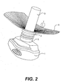
- Figure 2 is a perspective view of a wick-based delivery system according to an embodiment of our invention.
- Figures 3A and 3B are perspective views of a wick-based delivery system according to further embodiments of our invention.
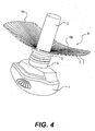
- Figure 4 is a perspective view of a wick-based delivery system according to another embodiment of our invention.
- Figure 5 is an elevational view of a wick-based delivery system according to a still further embodiment of our invention.
- Figure 6 is a top view illustrating the relationship of the porous wick and the capillary member of Figure 5.
- Figure 7 is an elevational, partial cut-away view of a wick-based delivery system according to yet another embodiment of our invention.
- Our invention relates generally to a wick-based delivery system for transporting a liquid from a reservoir to a surface that is exposed to the ambient air. Specifically, our invention relates to an improvement for a conventional wick-based system, like that shown in Figure 1.
- Figure 1 illustrates a conventional wick-based delivery system in its simplest form.
- Our invention may be configured to include many of the base features of a conventional device.
- the system includes a bottle 1 containing a liquid (not shown in Figure 1) and a wick 3.
- a neck closure 2 holds the wick 3 snugly in place within the neck 5 of the bottle 1.
- the wick 3 is preferably fixed in the bottle 1.
- the neck 5 of the bottle 1 can be shaped so that a cap 4 can be securely fastened over the wick 3 and the neck closure 2.
- an outer surface of the neck 5 of the bottle 1 may be threaded so that the cap 4 can be screwed onto the bottle 1 when the device is not in use.
- the bottle 1 and the neck closure 2 can be made of any suitable material that is leakproof.
- the size of the opening in the bottle 1 and the size of the neck closure 2 are dependent upon each other and upon the size of the wick 3 that is to be used with the device.
- the evaporative device of Figure 1 is assembled, and attached thereto is a capillary member, preferably, a capillary plate 6.
- the capillary plate 6 is preferably nonporous and includes one or more capillary channels 7 thereon. At least a portion of the capillary channels 7 is in substantial fluid communication with the wick 3.
- the capillary channels 7 are exposed to the ambient environment and are, individually, continuous from the position at which they are in intimate communication with the wick 3 to peripheral portions of the capillary plate 6.
- Other variations of channel-like capillaries may be used based on design requirements. In particular, in other embodiments, portions of the capillary channels 7 do not need to be exposed to the ambient environment.
- the capillary plate 6 is substantially wing-shaped, although we contemplate many suitable shapes and sizes. Also, according to this embodiment, the capillary plate 6 is preferably approximately .750 (1.905 cm) inches wide by 1.50 inches (3.81 cm) long, although such is merely exemplary. According to design preferences, the capillary plate 6 should be sized to effectuate an optimal release of fragrance. This sizing will likely be based on at least, the properties of the liquid used, the emanation rate of the wick 3, and various emanation preferences.
- the capillary channels 7 are preferably V-shaped in cross section. Also, the V-shaped capillary channels 7 are preferably 0.007 inches (0.1778 mm) wide at the surface of the capillary plate 6, 0.002 inches (0.0508 mm) wide at the base of the channel, and 0.017 inches (0.438 mm) deep. Notwithstanding, other shapes and sizes may be equally effective at transporting the liquid via capillary action from the wick 3. Generally, any shape and size that allows the liquid contained within the bottle 1 to be transported by capillary action will suffice. Further, as will be apparent to one of ordinary skill, the number or length of the capillary channels 7 will have a direct effect on the amount of liquid emanated from the capillary member.
- the capillary channels 7 are shown on the top (i.e., the side furthest from the bottle 1) of the capillary plate 6, such is not required. In fact, we contemplate that the capillary channels 7 may be formed on the underside (i.e., the side closest to the bottle 1) of the capillary plate 6. By placing the capillary channels 7 on the underside, for example, dust and other airborne impediments are less likely to collect in the capillary channels 7. In other embodiments, the capillary member may reside in other orientations relative to the porous wick. By way of illustration, the capillary member may be disposed such that the capillary channels 7 are positioned lengthwise against the wick 3.
- the capillary channels 7 are used, any surface having exposed capillary pathways along which a liquid can be drawn may be used as the capillary member.
- the capillary pathways may be continuous from the wick 3 to the periphery of the capillary plate 6, like the capillary channels 7 of Figure 2, or otherwise arranged to provide flow of liquid.
- the capillary plate 6 is non-porous, such that liquid can flow along the capillary pathways, on a surface thereof, but not through the capillary plate 6, as would happen in a conventional wicking substrate.
- the wick 3 is constructed such that the liquid contained within the bottle 1 is drawn through the porous wick 3 via capillary action. Then, as the liquid reaches an outer surface of the wick 3 exposed to the ambient air, the liquid evaporates, thereby releasing, for example, a liquid fragrance to the ambient air. Unlike conventional devices, however, as the liquid reaches the outer surface of the wick 3, the capillary channels 7 of the capillary plate 6 draw liquid, also by capillary action, from the wick 3. The liquid drawn to capillary plate 6 is also drawn along capillary channels 7.
- the liquid is introduced to the ambient air via both the outer surface of the wick 3 and the capillary plate 6.
- the amount of liquid released to the atmosphere is increased.
- the addition of the capillary channels 7 causes the release of the liquid to the ambient air at a more constant rate than can be achieved through the use of only a wick 3. Essentially, this configuration allows for an increased, substantially constant emanation rate.
- the capillary plate 6 of Figure 2 may also be detachably secured to the wick 3.
- the capillary plate 6 may be manufactured so that an aperture through the capillary plate 6 allows the capillary plate 6 to be slid over the wick 3.
- the bottom of the capillary plate 6 may come to rest on the neck closure 2 of the bottle 1 or on the neck 5 of the bottle 1.
- the outer perimeter of the wick 3 and the aperture through the capillary plate 6 may be formed so as to create an interference fit such that the capillary plate 6 comes to rest on an elevation of the protruding wick 3.
- liquid is drawn from the wick 3 to the capillary plate 6.
- the capillary channels 7, because of their communication with the wick 3, further disperse the liquid drawn by the wick 3.
- the capillary plate 6 can preferably be reused with a replacement evaporative device. Specifically, when all of the liquid contained within the bottle 1 of the embodiment shown in Figure 2 is dispersed, the capillary plate 6 can be detached and reattached to a replacement evaporative device.
- a replacement evaporative device Such a replacement generally includes those parts shown in Figure 1, although it only need include a liquid, a container for the liquid, and a wick.
- FIG. 2 shows all of the components just discussed as an integral unit, designed to stand alone as, for example, an air freshener. We also envision that the unit could be designed to removably attach to a housing 10. Illustrative examples of this embodiment are depicted in Figures 3A and 3B. As shown in these figures, a housing 10 having one or more vents 11 therethrough is used to contain the evaporative device of Figure 2. Preferably, the housing 10 and the bottle 1 are manufactured such that an outer surface of the bottle 1 can be engaged with an inner surface of the housing 10, although any detachable securement will suffice.
- the housing 10a part of the device By making the housing 10a part of the device, the overall aesthetics of the device are improved and the surfaces of the wick 3 and the capillary plate 6 are not exposed to external forces that may result in, for example, damage to the wick 3.
- the vents 11 allow liquid vapors emanated from the wick 3 and/or the capillary plate 6 to freely pass into the ambient air.
- the housing 10 may be reused. Generally, once the liquid contained within the bottle has evaporated completely, the entire device, i.e., the bottle 1, the wick 3, and anything connected thereto, are disposed of, and a replacement is purchased. However, since the housing 10 is a separate unit from which the device can be removed, a replacement device can be purchased and inserted into the housing 10. While we contemplate that the capillary plate 6 may be an integral portion of the evaporative device and thereby sold as part of the replacement device, we also contemplate the capillary plate 6 being fixed to the housing 10.
- a replacement for detachable attachment to the housing 10 does not include the capillary plate 6, thereby giving the user the benefits associated with the capillary plate 6, but without having to purchase it as part of a replacement.
- the housing 10 contains the capillary plate 6 such that, when a replaceable wick-based evaporative system is contained within the housing 10, the wick 3 and the capillary plate 6 are in contact with each other.
- the liquid supply is exhausted from the device, only the bottle 1, wick 3, and neck closure 2 (if used) are disposed of.
- a replacement contains only these components, as well as a fresh supply of evaporative liquid.
- the mating of the wick 3 and the capillary plate 6 may be one of several possible so that the wick 3 is in fluid contact with the capillary channels 7 of the capillary plate 6 when the replacement is inserted.
- Figure 4 shows a device similar to that of Figure 2, with the exception that the capillary plate 6 consists of two portions, i.e., capillary partial-plates 6a, 6b. While the operation of the device of Figure 4 is substantially the same to that of the device of Figure 2, using the capillary partial-plates 6a, 6b allows one to regulate the amount of liquid released to the ambient air. In particular, when both of the capillary partial-plates 6a, 6b are in communication with the wick 3, the device acts as the embodiment illustrated in Figure 2. However, when one of the capillary partial-plates 6a, 6b is no longer in communication with the wick 3, less liquid is emanated to the ambient air.
- the capillary partial plates 6a, 6b may either be entirely removable from the device, or they may be actuatable in a direction away from the wick 3.
- the capillary partial plates 6a, 6b function to transfer the liquid from the wick 3 for release to the ambient air only when in contact with the wick 3.
- the capillary partial plates 6a, 6b can be actuated away from the wick 3, the wick 3 is thus allowed to be inserted and withdrawn for purposes of replacement when no liquid remains.
- the capillary partial plates 6a, 6b are removed from communication with the wick 3, less liquid is emanated. As such, the useful life of the refill may be extended.
- FIG. 4 shows only two capillary partial- plates 6a, 6b, we anticipate that more capillary partial-plates 6a, 6b could be utilized.
- the capillary partial-plates 6a, 6b is to provide for an adjustable emanation device, it should be understood that the more capillary partial-plates 6a, 6b that are utilized, the greater the capability for adjustment.
- Figure 5 shows an emanation device including a bottle 1 with a neck 5, a neck closure 2, a porous wick 3a, and a capillary member formed as a capillary insert 8, with one or more capillary channels 9 formed thereon.
- the function and construction of the bottle 1, the neck 5, the neck closure 2, and the wick 3a is similar to that of the embodiments discussed previously.
- the wick 3a has an aperture formed in an axial direction therein, creating an inner surface 3i of the wick 3a, as seen in Figure 6.
- the aperture may extend throughout the entire length of the wick 3a, thereby rendering the wick 3a hollow, the aperture may only extend partially along the length of the wick 3a, thereby forming a bore in the wick 3a. Regardless of the length of the aperture, it should be understood that the inner surface 3i of the wick 3a created as a result of the aperture is exposed to the ambient environment, and, as such, liquid transferred by the wick 3a from the bottle 1 is emanated therefrom.
- the capillary insert 8 is designed for insertion into the aperture of the wick 3a and is preferably nonporous. When inserted, the capillary channels 9 of the capillary insert 8 are in communication with the inner surface 3i of the wick 3a. As would be appreciated, the presence of capillary insert 8 reduces (or prevents) the exposure of inner surface 3i to the ambient environment. However, as a result of this communication, the capillary channels 9 of the capillary insert 8 transfer liquid emanated from the inner surface 3i of the wick 3a, via capillary action, along their respective lengths.
- insertion of the capillary insert 8 into the aperture formed in the wick 3 a results in a slidable engagement between the capillary insert 8 and the inner surface 3i of the wick 3a.
- the amount of surface area of the capillary channels 9 that is exposed to the ambient air can be controlled. Specifically, when the capillary insert 8 is moved within the wick 3a closer to the bottle 1, less of the capillary insert 8 is exposed to the ambient air, above the wick 3a. As a result, relatively less liquid is emanated to the ambient air. Conversely, when the capillary insert 8 is moved within the wick 3a away from the bottle 1, more of the capillary insert 8 is exposed to the ambient air, above the wick 3a. As a result, relatively more liquid is emanated.
- our invention allows a user to achieve a preferred amount of emanation from the wick 3a by performing a simple adjustment.
- Figure 7 is a partial cut-away view illustrating still another embodiment of our invention.
- the wick 3a and the capillary insert 8 are identical to those of the embodiments of Figure 5 and Figure 6.
- the embodiment of Figure 7 provides a self-adjusting feature. More specifically, the embodiment of Figure 7 is capable of automatically adjusting the position of the capillary insert 8 within the wick 3a based on a change in temperature.
- the evaporative system is enclosed in a housing 10.
- the housing 10 may resemble those of Figures 3A and 3B, although it may be of myriad shapes and sizes.
- a heat sensitive member 12 is connected to both the housing 10 and the capillary insert 8.
- the heat sensitive member 12 is preferably substantially S-shaped and is sensitive to heat.
- the heat sensitive member 12 is preferably made of bimetal.
- an overall vertical length of the heat sensitive member 12 shortens, as the three central portions A, B, and C of the heat sensitive member 12 each becomes more horizontally disposed. Conversely, as the temperature of the heat sensitive member 12 increases, the heat sensitive member 12 lengthens in a vertical direction, with the portions A, B, and C of the heat sensitive member 12 becoming more vertically disposed.
- the shortening of the heat sensitive member 12 in cooler temperatures displaces the capillary insert 8 in a direction away from the bottle 1, and, therefore, more of the capillary insert 8 is exposed to the ambient air.
- the lengthening of the heat sensitive member 12 in warmer temperatures displaces the capillary insert 8 in a direction toward the bottle 1, and, therefore, less of the capillary insert 8 is exposed to the ambient air.
- This adjustability is advantageous because the temperature of the ambient air directly influences the rate of emanation of a liquid from a wick-based evaporative system. In particular, the warmer the ambient air, the quicker the rate of evaporation of the liquid, and, conversely, the cooler the ambient air, the slower the rate of evaporation of the liquid.
- the heat sensitive member 12 is shown in Figure 7 as being substantially S-shaped, we contemplate that the heat sensitive member 12 may be of many shapes, configurations, and/or materials. Furthermore, the embodiment shown in Figure 7 may be constructed such that, similar to that discussed with regard to the embodiment of Figures 3A and 3B, the housing 10 and the emanation device are detachably attachable with respect to each other. Ideally, the bottle 1, the wick 3a, and the neck closure 2 (if used) comprise a replacement that can be discarded when no liquid remains in the bottle 1. Accordingly, the housing 10, the heat sensitive member 12, and the capillary insert 8 are reused.
- the embodiment of Figure 7 is particularly well suited for use in automobiles, in which temperature fluctuation is common.
- a conventional device an insufficient amount of liquid may be dispersed at cooler temperatures, while too much liquid may be dispersed at relatively warmer temperatures.
- the present embodiment is particularly well suited for this type of application, and the housing 10 may be specifically formed for mounting our evaporative system in an automobile.
- the housing 10 may be detachably secured to a vent found in the automobile.
- liquid drawn from the bottle 1 by the wick 3 or 3a is dispersed to the ambient air via both the wick 3 or 3a and the capillary member.
- the wick 3 or 3a exposed to the ambient air and not in contact with the capillary member may be encased by a cover.
- the wick 3 or 3a may be shortened such that only a minimal or no portion of the wick 3 or 3a extends outside of the bottle 1.
- the wick is preferably made of micro-porous plastic
- the capillary insert is made of polypropylene or PET by injection molding, and the liquid to be dispersed is fragrance oil.
- Our invention is not limited to these preferences, however. Other known materials may be substituted, as desired.
- An evaporative device comprising: a container for holding a liquid, the container having an opening; a porous wick extending through the opening such that a portion of the wick contacts the liquid held within the container and a portion of the wick is exposed to the ambient environment, wherein the wick transfers the liquid from the container; and a capillary member having a surface in communication with a portion of the wick, wherein one or more capillary pathways are disposed along the surface of the capillary member along which liquid, transferred by the wick from the container, is drawn by capillary action for dispersion to the ambient air.
- the capillary member may be a capillary plate having one or more capillary channels, and wherein a portion of the capillary channels may be in communication with a portion of the wick such that the capillary channels transfer liquid from the wick for dispersion to the ambient environment.
- the capillary plate may be substantially wing shaped.
- An evaporative device comprising: a container for holding a liquid, the container haveing an opening; a porous wick extending through the opening such that a portion of the wick contacts the liquid held within the container and a portion of the wick extends outside of the container such that the wick transfers the liquid from the container; and a capillary plate having a surface in communication with a portion of the wick, wherein the surface has one or more capillary pathways along which liquid, transferred by the wick from the container, is drawn by capillary action for dispersion to the ambient environment.
- the capillary plate may be nonporous.
- the capillary plate may be substantially wing shaped.
- the exposed capillary pathways may be substantially continuous along their lengths.
- the exposed capillary pathways may comprise one or more capillary channels and a portion of the capillary channels may be in communication with a portion of the wick extending outside the container.
- the capillary channels may be substantially V-shaped in cross section.
- the capillary plate may be detachably secured to one or both of the wick and the container.
- the said surface may be one of a top and a bottom of the capillary plate.
- the evaporative device may further comprise a cover that encases a portion of the portion of the wick extending outside of the container.
- the evaporative device may have plural capillary plates, each having one or more capillary pathways, and the capillary pathways may be in communication with the portion of the wick extending outside of the container.
- the plural capillary plates may be movable such that the capillary pathways of each are removable from communication with the portion of the wick extending outside of the container.
- the plural capillary plates may be actuatable in a direction away from the wick to separate the capillary pathways thereof from communication with the portion of the wick exposed to the ambient air.
- the capillary pathways may be exposed on the surface of the capillary plate.
- the capillary plate may be composed of polyethylene.
- An evaporative system comprising: an evaporative device as described above; and a housing for containing at least a portion of the evaporative device.
- the evaporative device may be detachably attached to the housing.
- the capillary plate may be fixed to the housing, and the container and the wick may be detachably attachable to the housing and the capillary plate.
- Our invention provides a device useful as a means to transport a liquid from a container to a surface that is exposed to the ambient air.
- the surface may be either a surface of a porous wick, a capillary member having one or more capillary channels, or a combination of both a surface of a porous wick and a capillary member having one or more capillary channels.
- This device can preferably be used, for example, to dispense fragrances, insecticides, and any other vaporizable materials into the ambient air.
Abstract
Description
- Our invention relates to a device for transporting liquids, such as insect repellants, fragrances, or insecticides, from a reservoir to a surface exposed to the ambient air.
- Devices that release vapors into the ambient air are well-known in the art. Generally, the purpose of these devices is to deodorize, provide fragrance to, and/or disinfect the ambient air, or to distribute toxins into the air to kill or repel unwanted pests, such as mosquitoes.
- To achieve the goal of dispersing active particles into the air, a number of methods has been employed. For example, aerosol containers have been used to atomize particles into the air upon the activation of a trigger by a user.
- Also, other methods utilize the evaporative properties of liquids, or other vaporizable materials, to cause vapors with desired properties to be distributed into the ambient air. One such known evaporative technique, illustrated in Figure 1, utilizes a wick to deliver a vaporizable liquid from a reservoir to a surface exposed to the ambient air. An example of such a product is GLADE® PLUGINS® Scented Oil, by S.C. Johnson & Son, Inc. (Racine, WI).
- As shown in Figure 1, the reservoir from which the liquid is transported is a
bottle 1 having a conventional shape. Thebottle 1 contains a vaporizable liquid. (The level of the liquid is not shown in thebottle 1.) Awick 3 is preferably shaped to fit snugly into aneck 5 of thebottle 1. It is also preferable to use aneck closure 2 to hold thewick 3 in place and to prevent leakage around theneck 5 of thebottle 1. The fit between theneck closure 2 and thebottle 1 should be sufficient to prevent leakage of the liquid from thebottle 1. Likewise, the fit between theneck closure 2 and thewick 3 should be sufficient to prevent leakage. - When assembled, the
wick 3 is arranged such that a portion thereof is in contact with the liquid and another portion thereof is exposed to the ambient air. Arranged as such, thewick 3 transports the liquid to the surface of the wick by a principle called capillary action. In particular, thewick 3 material contains numerous small, internal, interconnecting pores. When liquid contacts those pores, it is elevated by principles of surface tension due to attractive forces, causing the liquid to be drawn into adjacent pores. As this process continues, the liquid migrates through the porous material. As the liquid is drawn from thebottle 1, it is transported up theporous wick 3 and eventually reaches a surface of the portion of thewick 3 exposed to the ambient air. As the liquid reaches this exposed surface, the liquid evaporates and disperses into the air. - While, as just described, it is conventionally known to expose a surface of the wick to the air, it is also known to provide multiple porous members, in fluid communication with each other, with a surface of one porous member being the exposed surface and another porous member contacting the fluid. For example, as shown in
U.S. Patent No. 4,413,779 , a glass container contains a fluid into which two rigid porous nylon wicks extend. The wicks also contact a rigid plastic porous element. In use, the wicks transport the fluid from the glass container to the porous element, which releases the fluid to the ambient air. - Such wick-based evaporative methods have become relatively commonplace and are effective at dispersing an evaporative liquid to the ambient air. However, they do have drawbacks. In fact, a prevalent problem associated with these methods is their inability to provide a linear release of the liquid to be emanated to ambient air. For example, while a given amount of liquid is emanated during the first day of use of a wick-based air freshener, the amount emanated decreases continually through successive days and weeks.
- As an attempt to overcome the problems associated with conventional evaporative devices, some devices provide heat to the wick surface, some utilize electric fans, and some a combination of the two. Generally, the combined apparatus is designed to be plugged into an electrical outlet, to provide power for the electrically operated features. The heater raises ambeient temperature adjacent to the wick, thereby aiding release of the liquid, while the fan blows a stream of air across the wick. In theory, this fan increases the rate of emanation of the liquid from the wick. While in such systems the evaporative device used in conjunction with the heating device and/or the fan can usually be replaced by a refill, thereby allowing the electrically operated components to be reused, the heater device, fan, and necessary electronic components increase the overall price of the evaporative system.
- A further method of dispensing vapors into the air is illustrated in
U.S. Patent No. 4,913,350 . According to this disclosure, an external capillary member is partially in contact with a liquid fragrance contained in a reservoir and partially in contact with the ambient air. The external capillary member has one or more external capillary cavities formed in the outer surface of the external capillary members. Like the porous cavities in conventional wicks, the capillary cavities draw the liquid to be emanated from the reservoir to the portion of the capillary member exposed to the ambient air. Once exposed, the liquid is released into the ambient air. - The use of the capillary channels is seen to be advantageous because, theoretically, the fragrance is delivered to the ambient air at a more constant rate, thereby overcoming the above-discussed problem associated with the conventional porous wick. In practice, however, open capillary release systems also have drawbacks. Most noticeably, the capillary member has proven to be inferior, and even ineffective, at removing many liquid formulations from a reservoir (i.e., depending on viscosity, surface tension, etc.).
- As such, there is a need in the art for a cost-effective evaporative method of releasing a liquid into the ambient air that reliably releases the liquid at a constant rate.
- An object of our invention is to provide a cost-effective, wick-based evaporative device that remedies those problems discussed above.
- In one aspect of our invention, an evaporative device includes a container, a porous wick, and a capillary member. The container holds a liquid and has an opening. The porous wick extends through the opening in the container such that a portion of the wick contacts the liquid held within the container and a portion of the wick is exposed to the ambient air. The wick transfers the liquid from the container. The capillary member has a surface in communication with a portion of the wick. One or more capillary pathways are disposed on the surface of the capillary member along which liquid, transferred by the wick from the container, is drawn by capillary action for dispersion to the ambient air.
- According to another aspect of our invention, an evaporative device includes a container, a porous wick, and a capillary plate. The container holds a liquid and has an opening. The porous wick extends through the opening such that a portion of the wick contacts the liquid held within the container and a portion of the wick extends outside of the container. The wick transfers the liquid from the container. The capillary plate has a surface in communication with a portion of the wick. The surface has one or more capillary pathways along which liquid, transferred by the wick from the container, is drawn by capillary action for dispersion to the ambient environment.
- According to yet another aspect of our invention, an evaporative device includes a container, a porous wick, and a capillary insert. The container holds a liquid and has an opening. The porous wick has an aperture extending axially therein and the wick extends through the opening of the container such that a portion of the wick contacts the liquid held within the container and a portion of the wick is exposed to the ambient air. The wick transfers liquid from the container. The capillary insert is insertable into the aperture in the wick, such that a surface of the capillary insert is in communication with the wick. The surface has a plurality of capillary pathways along which liquid transferred by the wick from the container is drawn by capillary action for dispersion to the ambient environment.
- According to a further aspect of our invention; an evaporative system includes a container, a porous wick, a capillary insert, a housing, and a heat sensitive member. The container holds a liquid and has an opening. The porous wick has an aperture extending axially therein forming an inner surface of the wick that is exposed to the ambient environment, and the wick extends through the opening of the container such that a portion of the wick contacts the liquid held within the container and a portion of the wick is exposed to the ambient air. The wick transfers liquid from the container to the inner surface of the wick. The capillary insert is insertable into the aperture in the wick, thereby forming a slidable engagement between the inner surface of the wick and a surface of the capillary insert. The surface has one or more capillary pathways along which liquid, transferred by the wick from the container, is drawn by capillary action for dispersion to the ambient air. The housing contains at least a portion of one or more of the container, the porous wick, and the capillary insert. The heat sensitive member is in communication with both the housing and the capillary insert and varies in length based on ambient temperature. When the heat sensitive member varies in length, the change in length causes displacement of the capillary insert within the aperature of the work.
- A better understanding of these and other features and advantages of our invention may be had by reference to the drawings and to the accompanying description, in which preferred embodiments of the invention are illustrated and described.
- Figure 1 is an elevational, exploded view of a conventional wick-based delivery system.
- Figure 2 is a perspective view of a wick-based delivery system according to an embodiment of our invention.
- Figures 3A and 3B are perspective views of a wick-based delivery system according to further embodiments of our invention.
- Figure 4 is a perspective view of a wick-based delivery system according to another embodiment of our invention.
- Figure 5 is an elevational view of a wick-based delivery system according to a still further embodiment of our invention.
- Figure 6 is a top view illustrating the relationship of the porous wick and the capillary member of Figure 5.
- Figure 7 is an elevational, partial cut-away view of a wick-based delivery system according to yet another embodiment of our invention.
- Throughout the figures, like or corresponding reference numerals have been used for like or corresponding parts.
- Our invention relates generally to a wick-based delivery system for transporting a liquid from a reservoir to a surface that is exposed to the ambient air. Specifically, our invention relates to an improvement for a conventional wick-based system, like that shown in Figure 1.
- As discussed above, Figure 1 illustrates a conventional wick-based delivery system in its simplest form. Our invention may be configured to include many of the base features of a conventional device. In particular, the system includes a
bottle 1 containing a liquid (not shown in Figure 1) and awick 3. Preferably, aneck closure 2 holds thewick 3 snugly in place within theneck 5 of thebottle 1. Thewick 3 is preferably fixed in thebottle 1. - In addition, the
neck 5 of thebottle 1 can be shaped so that acap 4 can be securely fastened over thewick 3 and theneck closure 2. For example, an outer surface of theneck 5 of thebottle 1 may be threaded so that thecap 4 can be screwed onto thebottle 1 when the device is not in use. - The
bottle 1 and theneck closure 2 can be made of any suitable material that is leakproof. Of course, the size of the opening in thebottle 1 and the size of theneck closure 2 are dependent upon each other and upon the size of thewick 3 that is to be used with the device. - Turning now to Figure 2, a preferred embodiment of our invention will be described. As can be seen in Figure 2, the evaporative device of Figure 1 is assembled, and attached thereto is a capillary member, preferably, a
capillary plate 6. Thecapillary plate 6 is preferably nonporous and includes one or morecapillary channels 7 thereon. At least a portion of thecapillary channels 7 is in substantial fluid communication with thewick 3. Thecapillary channels 7 are exposed to the ambient environment and are, individually, continuous from the position at which they are in intimate communication with thewick 3 to peripheral portions of thecapillary plate 6. Other variations of channel-like capillaries may be used based on design requirements. In particular, in other embodiments, portions of thecapillary channels 7 do not need to be exposed to the ambient environment. - As illustrated, the
capillary plate 6 is substantially wing-shaped, although we contemplate many suitable shapes and sizes. Also, according to this embodiment, thecapillary plate 6 is preferably approximately .750 (1.905 cm) inches wide by 1.50 inches (3.81 cm) long, although such is merely exemplary. According to design preferences, thecapillary plate 6 should be sized to effectuate an optimal release of fragrance. This sizing will likely be based on at least, the properties of the liquid used, the emanation rate of thewick 3, and various emanation preferences. - As shown in Figure 2, the
capillary channels 7 are preferably V-shaped in cross section. Also, the V-shapedcapillary channels 7 are preferably 0.007 inches (0.1778 mm) wide at the surface of thecapillary plate 6, 0.002 inches (0.0508 mm) wide at the base of the channel, and 0.017 inches (0.438 mm) deep. Notwithstanding, other shapes and sizes may be equally effective at transporting the liquid via capillary action from thewick 3. Generally, any shape and size that allows the liquid contained within thebottle 1 to be transported by capillary action will suffice. Further, as will be apparent to one of ordinary skill, the number or length of thecapillary channels 7 will have a direct effect on the amount of liquid emanated from the capillary member. Specifically, as the number or length of thecapillary channels 7 increases, the greater the amount of liquid emanated. Likewise, as the number or length of thecapillary channels 7 decreases, the lesser the amount of liquid emanated. While the makeup of thecapillary channels 7 will in this manner influence an amount of emanation, one of skill in the art will of course understand that the physical properties of the liquid will also dictate the emanation amount. - Also, although not required, we have found that when a V-shaped cross section is used for the
capillary channels 7 on thecapillary plate 6, it is preferable for the point, or apex, of the V-shape to be in contact with thewick 3. Such an arrangement provides an effective way of drawing, via capillary action, evaporative liquid from thewick 3. Such is not required, however.
Any contact point on acapillary channel 7 that fosters capillary action will promote the accumulation of liquid within thatcapillary channel 7 and will thus achieve the desired emanation. - Further, while the
capillary channels 7 are shown on the top (i.e., the side furthest from the bottle 1) of thecapillary plate 6, such is not required. In fact, we contemplate that thecapillary channels 7 may be formed on the underside (i.e., the side closest to the bottle 1) of thecapillary plate 6. By placing thecapillary channels 7 on the underside, for example, dust and other airborne impediments are less likely to collect in thecapillary channels 7. In other embodiments, the capillary member may reside in other orientations relative to the porous wick. By way of illustration, the capillary member may be disposed such that thecapillary channels 7 are positioned lengthwise against thewick 3. - Moreover, although in this preferred embodiment, the
capillary channels 7 are used, any surface having exposed capillary pathways along which a liquid can be drawn may be used as the capillary member. Further, the capillary pathways may be continuous from thewick 3 to the periphery of thecapillary plate 6, like thecapillary channels 7 of Figure 2, or otherwise arranged to provide flow of liquid. In preferred embodiments, thecapillary plate 6 is non-porous, such that liquid can flow along the capillary pathways, on a surface thereof, but not through thecapillary plate 6, as would happen in a conventional wicking substrate. - In operation, the
wick 3 is constructed such that the liquid contained within thebottle 1 is drawn through theporous wick 3 via capillary action. Then, as the liquid reaches an outer surface of thewick 3 exposed to the ambient air, the liquid evaporates, thereby releasing, for example, a liquid fragrance to the ambient air. Unlike conventional devices, however, as the liquid reaches the outer surface of thewick 3, thecapillary channels 7 of thecapillary plate 6 draw liquid, also by capillary action, from thewick 3. The liquid drawn tocapillary plate 6 is also drawn alongcapillary channels 7. - As should thus be apparent, according to the embodiment shown in Figure 2, the liquid is introduced to the ambient air via both the outer surface of the
wick 3 and thecapillary plate 6. As a result, the amount of liquid released to the atmosphere is increased. We have found that the addition of thecapillary channels 7 causes the release of the liquid to the ambient air at a more constant rate than can be achieved through the use of only awick 3.
Essentially, this configuration allows for an increased, substantially constant emanation rate. - The
capillary plate 6 of Figure 2 may also be detachably secured to thewick 3. For example, thecapillary plate 6 may be manufactured so that an aperture through thecapillary plate 6 allows thecapillary plate 6 to be slid over thewick 3. The bottom of thecapillary plate 6 may come to rest on theneck closure 2 of thebottle 1 or on theneck 5 of thebottle 1. Alternatively, the outer perimeter of thewick 3 and the aperture through thecapillary plate 6 may be formed so as to create an interference fit such that thecapillary plate 6 comes to rest on an elevation of the protrudingwick 3. In either design, liquid is drawn from thewick 3 to thecapillary plate 6. When this is achieved, thecapillary channels 7, because of their communication with thewick 3, further disperse the liquid drawn by thewick 3. - By making the
capillary plate 6 detachably securable, thecapillary plate 6 can preferably be reused with a replacement evaporative device. Specifically, when all of the liquid contained within thebottle 1 of the embodiment shown in Figure 2 is dispersed, thecapillary plate 6 can be detached and reattached to a replacement evaporative device. Such a replacement generally includes those parts shown in Figure 1, although it only need include a liquid, a container for the liquid, and a wick. - The embodiment of Figure 2 shows all of the components just discussed as an integral unit, designed to stand alone as, for example, an air freshener. We also envision that the unit could be designed to removably attach to a
housing 10. Illustrative examples of this embodiment are depicted in Figures 3A and 3B. As shown in these figures, ahousing 10 having one ormore vents 11 therethrough is used to contain the evaporative device of Figure 2. Preferably, thehousing 10 and thebottle 1 are manufactured such that an outer surface of thebottle 1 can be engaged with an inner surface of thehousing 10, although any detachable securement will suffice. By making the housing 10a part of the device, the overall aesthetics of the device are improved and the surfaces of thewick 3 and thecapillary plate 6 are not exposed to external forces that may result in, for example, damage to thewick 3. Thevents 11 allow liquid vapors emanated from thewick 3 and/or thecapillary plate 6 to freely pass into the ambient air. - An advantage of making the
housing 10 and the emanation device detachable from each other is that thehousing 10 may be reused. Generally, once the liquid contained within the bottle has evaporated completely, the entire device, i.e., thebottle 1, thewick 3, and anything connected thereto, are disposed of, and a replacement is purchased. However, since thehousing 10 is a separate unit from which the device can be removed, a replacement device can be purchased and inserted into thehousing 10. While we contemplate that thecapillary plate 6 may be an integral portion of the evaporative device and thereby sold as part of the replacement device, we also contemplate thecapillary plate 6 being fixed to thehousing 10. As such, when all of the liquid within the bottle is used, a replacement for detachable attachment to thehousing 10 does not include thecapillary plate 6, thereby giving the user the benefits associated with thecapillary plate 6, but without having to purchase it as part of a replacement. - As shown in Figures 3A and 3B, for example, the
housing 10 contains thecapillary plate 6 such that, when a replaceable wick-based evaporative system is contained within thehousing 10, thewick 3 and thecapillary plate 6 are in contact with each other. However, when the liquid supply is exhausted from the device, only thebottle 1,wick 3, and neck closure 2 (if used) are disposed of. A replacement contains only these components, as well as a fresh supply of evaporative liquid. As discussed above, the mating of thewick 3 and thecapillary plate 6 may be one of several possible so that thewick 3 is in fluid contact with thecapillary channels 7 of thecapillary plate 6 when the replacement is inserted. - Illustrating another preferred embodiment of our invention, Figure 4 shows a device similar to that of Figure 2, with the exception that the
capillary plate 6 consists of two portions, i.e., capillary partial-plates plates plates wick 3, the device acts as the embodiment illustrated in Figure 2. However, when one of the capillary partial-plates wick 3, less liquid is emanated to the ambient air. Emanation decreases because the liquid transferred from thebottle 1 by thewick 3 will only transfer through thosecapillary channels 7 that remain in contact with thewick 3. When neither of the capillary partial-plates wick 3, the device acts as the conventional device illustrated in Figure 1, discussed above. - In order to impede the
capillary channels 7 of one or both of the capillarypartial plates wick 3, the capillarypartial plates wick 3. Thus, in this embodiment, the capillarypartial plates wick 3 for release to the ambient air only when in contact with thewick 3. Moreover, because the capillarypartial plates wick 3, thewick 3 is thus allowed to be inserted and withdrawn for purposes of replacement when no liquid remains. Also, when the capillarypartial plates wick 3, less liquid is emanated. As such, the useful life of the refill may be extended. - Furthermore, while the embodiment of Figure 4 shows only two capillary partial-
plates plates plates plates - Turning now to another embodiment of our invention, Figure 5 shows an emanation device including a
bottle 1 with aneck 5, aneck closure 2, aporous wick 3a, and a capillary member formed as acapillary insert 8, with one or morecapillary channels 9 formed thereon. The function and construction of thebottle 1, theneck 5, theneck closure 2, and thewick 3a is similar to that of the embodiments discussed previously. In this embodiment, however, thewick 3a has an aperture formed in an axial direction therein, creating aninner surface 3i of thewick 3a, as seen in Figure 6. While the aperture may extend throughout the entire length of thewick 3a, thereby rendering thewick 3a hollow, the aperture may only extend partially along the length of thewick 3a, thereby forming a bore in thewick 3a. Regardless of the length of the aperture, it should be understood that theinner surface 3i of thewick 3a created as a result of the aperture is exposed to the ambient environment, and, as such, liquid transferred by thewick 3a from thebottle 1 is emanated therefrom. - The
capillary insert 8 is designed for insertion into the aperture of thewick 3a and is preferably nonporous. When inserted, thecapillary channels 9 of thecapillary insert 8 are in communication with theinner surface 3i of thewick 3a. As would be appreciated, the presence ofcapillary insert 8 reduces (or prevents) the exposure ofinner surface 3i to the ambient environment. However, as a result of this communication, thecapillary channels 9 of thecapillary insert 8 transfer liquid emanated from theinner surface 3i of thewick 3a, via capillary action, along their respective lengths. - Preferably, insertion of the
capillary insert 8 into the aperture formed in thewick 3 a results in a slidable engagement between thecapillary insert 8 and theinner surface 3i of thewick 3a. When thecapillary insert 8 is slidable within thewick 3a, the amount of surface area of thecapillary channels 9 that is exposed to the ambient air can be controlled. Specifically, when thecapillary insert 8 is moved within thewick 3a closer to thebottle 1, less of thecapillary insert 8 is exposed to the ambient air, above thewick 3a. As a result, relatively less liquid is emanated to the ambient air. Conversely, when thecapillary insert 8 is moved within thewick 3a away from thebottle 1, more of thecapillary insert 8 is exposed to the ambient air, above thewick 3a. As a result, relatively more liquid is emanated. - With this configuration, our invention allows a user to achieve a preferred amount of emanation from the
wick 3a by performing a simple adjustment. - Figure 7 is a partial cut-away view illustrating still another embodiment of our invention. In Figure 7, the
wick 3a and thecapillary insert 8 are identical to those of the embodiments of Figure 5 and Figure 6. However, the embodiment of Figure 7 provides a self-adjusting feature. More specifically, the embodiment of Figure 7 is capable of automatically adjusting the position of thecapillary insert 8 within thewick 3a based on a change in temperature. - As illustrated in Figure 7, the evaporative system is enclosed in a
housing 10. Thehousing 10 may resemble those of Figures 3A and 3B, although it may be of myriad shapes and sizes. A heatsensitive member 12 is connected to both thehousing 10 and thecapillary insert 8. The heatsensitive member 12 is preferably substantially S-shaped and is sensitive to heat. The heatsensitive member 12 is preferably made of bimetal. - In operation, as the temperature of the heat
sensitive member 12 decreases (as controlled by the ambient temperature), an overall vertical length of the heatsensitive member 12 shortens, as the three central portions A, B, and C of the heatsensitive member 12 each becomes more horizontally disposed. Conversely, as the temperature of the heatsensitive member 12 increases, the heatsensitive member 12 lengthens in a vertical direction, with the portions A, B, and C of the heatsensitive member 12 becoming more vertically disposed. As such, when attached to thehousing 10 and thecapillary insert 9, as shown in Figure 7, the shortening of the heatsensitive member 12 in cooler temperatures displaces thecapillary insert 8 in a direction away from thebottle 1, and, therefore, more of thecapillary insert 8 is exposed to the ambient air. Conversely, the lengthening of the heatsensitive member 12 in warmer temperatures displaces thecapillary insert 8 in a direction toward thebottle 1, and, therefore, less of thecapillary insert 8 is exposed to the ambient air. - This adjustability is advantageous because the temperature of the ambient air directly influences the rate of emanation of a liquid from a wick-based evaporative system. In particular, the warmer the ambient air, the quicker the rate of evaporation of the liquid, and, conversely, the cooler the ambient air, the slower the rate of evaporation of the liquid.
- While the heat
sensitive member 12 is shown in Figure 7 as being substantially S-shaped, we contemplate that the heatsensitive member 12 may be of many shapes, configurations, and/or materials. Furthermore, the embodiment shown in Figure 7 may be constructed such that, similar to that discussed with regard to the embodiment of Figures 3A and 3B, thehousing 10 and the emanation device are detachably attachable with respect to each other. Ideally, thebottle 1, thewick 3a, and the neck closure 2 (if used) comprise a replacement that can be discarded when no liquid remains in thebottle 1. Accordingly, thehousing 10, the heatsensitive member 12, and thecapillary insert 8 are reused. - In addition, we have found that the embodiment of Figure 7 is particularly well suited for use in automobiles, in which temperature fluctuation is common. In a conventional device, an insufficient amount of liquid may be dispersed at cooler temperatures, while too much liquid may be dispersed at relatively warmer temperatures. Accordingly, the present embodiment is particularly well suited for this type of application, and the
housing 10 may be specifically formed for mounting our evaporative system in an automobile. For example, thehousing 10 may be detachably secured to a vent found in the automobile. - According to each of the embodiments discussed herein, liquid drawn from the
bottle 1 by thewick wick wick wick wick wick bottle 1. - In each of the embodiments discussed above, the wick is preferably made of micro-porous plastic the capillary insert is made of polypropylene or PET by injection molding, and the liquid to be dispersed is fragrance oil. Our invention is not limited to these preferences, however. Other known materials may be substituted, as desired.
- The embodiments discussed above are representative of preferred embodiments of the present invention and are provided for illustrative purposes only. They are not intended to limit the scope of the invention. Although specific structures, dimensions, components, etc., have been shown and described, such are not limiting. Modifications and variations are contemplated within the scope of our invention, which is intended to be limited only by the scope of the accompanying claims.
Further embodiments are set out below.
An evaporative device comprising: a container for holding a liquid, the container having an opening; a porous wick extending through the opening such that a portion of the wick contacts the liquid held within the container and a portion of the wick is exposed to the ambient environment, wherein the wick transfers the liquid from the container; and a capillary member having a surface in communication with a portion of the wick, wherein one or more capillary pathways are disposed along the surface of the capillary member along which liquid, transferred by the wick from the container, is drawn by capillary action for dispersion to the ambient air.
The capillary member may be a capillary plate having one or more capillary channels, and wherein a portion of the capillary channels may be in communication with a portion of the wick such that the capillary channels transfer liquid from the wick for dispersion to the ambient environment. The capillary plate may be substantially wing shaped.
An evaporative device comprising: a container for holding a liquid, the container haveing an opening; a porous wick extending through the opening such that a portion of the wick contacts the liquid held within the container and a portion of the wick extends outside of the container such that the wick transfers the liquid from the container; and a capillary plate having a surface in communication with a portion of the wick, wherein the surface has one or more capillary pathways along which liquid, transferred by the wick from the container, is drawn by capillary action for dispersion to the ambient environment.
The capillary plate may be nonporous. The capillary plate may be substantially wing shaped.
The exposed capillary pathways may be substantially continuous along their lengths. The exposed capillary pathways may comprise one or more capillary channels and a portion of the capillary channels may be in communication with a portion of the wick extending outside the container. The capillary channels may be substantially V-shaped in cross section. The capillary plate may be detachably secured to one or both of the wick and the container. The said surface may be one of a top and a bottom of the capillary plate. The evaporative device may further comprise a cover that encases a portion of the portion of the wick extending outside of the container. The evaporative device may have plural capillary plates, each having one or more capillary pathways, and the capillary pathways may be in communication with the portion of the wick extending outside of the container. The plural capillary plates may be movable such that the capillary pathways of each are removable from communication with the portion of the wick extending outside of the container. The plural capillary plates may be actuatable in a direction away from the wick to separate the capillary pathways thereof from communication with the portion of the wick exposed to the ambient air. The capillary pathways may be exposed on the surface of the capillary plate. The capillary plate may be composed of polyethylene.
An evaporative system comprising: an evaporative device as described above; and a housing for containing at least a portion of the evaporative device.
The evaporative device may be detachably attached to the housing.
The capillary plate may be fixed to the housing, and the container and the wick may be detachably attachable to the housing and the capillary plate. - Our invention provides a device useful as a means to transport a liquid from a container to a surface that is exposed to the ambient air. The surface may be either a surface of a porous wick, a capillary member having one or more capillary channels, or a combination of both a surface of a porous wick and a capillary member having one or more capillary channels. This device can preferably be used, for example, to dispense fragrances, insecticides, and any other vaporizable materials into the ambient air.
Claims (10)
- An evaporative device comprising:a container (1) for holding a liquid, the container having an opening:characterized in that the wick (3a) has an axial aperture and the capillary member comprises an insert (8) designed to fit in the aperture, said capillary pathways comprising capillary channels (9) formed on the insert (8) such as to be in communication with an inner surface (3i) of the aperture of the wick (3a), to transfer liquid from said inner surface (3i) to said channels (9).a porous wick (3a) extending through the opening such that a portion of the wick contacts the liquid held within the container and a portion of the wick is exposed to the ambient environment, wherein the wick transfers the liquid from the container; anda capillary member (8) having a surface in communication with a portion of the wick, wherein one or more capillary pathways are disposed along the surface of the capillary member along which the liquid, transferred by the wick from the container, is drawn by capillary action for dispersion to the ambient air;
- A device according to claim 1 wherein the insert (8) is non-porous.
- A device according to claim 1 or 2 wherein the insert is in slidable engagement with the inner surface (3i) of the wick (3a) so that the amount of surface area of the capillary channels that is exposed to the ambient air is controllable.
- A device according to claim 3 further including a housing (10),
a container with a capillary member being enclosed by the housing (10); and
a heat sensitive member (12) connected both to the housing and the capillary insert (8) such that in warmer temperatures the heat sensitive member (12) displaces the insert (8) in a direction towards the bottle thereby reducing the amount of the insert (8) that is exposed to ambient air and in cooler temperature the heat sensitive member (12) displaces the insert in a direction away from the bottle thereby exposing more of the insert (8) to the ambient air. - A device according to claim 4 wherein the heat sensitive member (12) is substantially S-shaped, and preferably bi-metallic.
- A device according to any preceding claim wherein a cover is provided encasing the exposed portion of the wick that is not in contact with the insert (8).
- A device according to any preceding claim wherein the wick is made of micro-porous plastic and the insert is made of polypropylene or PET by injection molding.
- An evaporative device comprising:a container (1) for holding a liquid, the container having an opening:characterized in that said capillary member (6, 8) comprises a plurality of plates (6a, 6b) each selectively actuable towards and away from wick, or an insert (8) slidably movable in an axial aperture in the end of the wick, to control the amount of evaporation of liquid from the capillary member.a porous wick (3, 3a) extending through the opening such that a portion of the wick (3, 3a) contacts the liquid held within the container (1) and a portion of the wick (3, 3a) is exposed to the ambient environment, wherein the wick (3, 3a) transfers the liquid from the container (1); anda capillary member (6, 8) having a surface in communication with a portion of the wick, wherein one or more capillary pathways (7, 9) are disposed along the surface of the capillary member (6, 8) along which the liquid, transferred by the wick from the container, is drawn by capillary action for dispersion to the ambient air;
- An evaporative device system comprising:a housing for supporting a bottle of liquid to be evaporated having a wick protruding from a neck of the bottle,a capillary member (6, 8) attached to the housing and having a surface adapted to communicate with the wick, said surface having one or more capillary pathways for transferring liquid from the wick to be dispensed to the ambient air,characterized in that an actuator is provided to move the capillary member or portions thereof thereby controlling the amount of liquid dispensed to the ambient air, wherein the capillary member is optionally an insert (8) suitable to be slidably receivable in an axial aperture in a wick (3a).
- A refill for an evaporative device system comprising:a container (1) for holding a liquid, the container having an opening; anda porous wick (3a) extending through the opening such that a portion of the wick contacts the liquid held within the container and a portion of the wick is exposed to the ambient environment, wherein the wick transfers the liquid from the container; characterized in that the wick (3a) has an axial aperture adapted to receive an insert (8) designed to fit in the aperture, capillary channels (9) formed on the surface of the insert (8) in communication with an inner surface (3i) of the aperture to transfer liquid transferred by the wick from the container from said inner surface (3i) by capillary action to said channels (9) for dispersion to the ambient air.
Applications Claiming Priority (2)
| Application Number | Priority Date | Filing Date | Title |
|---|---|---|---|
| US10/777,079 US20050178345A1 (en) | 2004-02-13 | 2004-02-13 | Wick-based delivery system incorporating a capillary member |
| EP05713120A EP1713519A1 (en) | 2004-02-13 | 2005-02-08 | Wick-based delivery system incorporating a capillary member |
Related Parent Applications (1)
| Application Number | Title | Priority Date | Filing Date |
|---|---|---|---|
| EP05713120A Division EP1713519A1 (en) | 2004-02-13 | 2005-02-08 | Wick-based delivery system incorporating a capillary member |
Publications (2)
| Publication Number | Publication Date |
|---|---|
| EP1834653A2 true EP1834653A2 (en) | 2007-09-19 |
| EP1834653A3 EP1834653A3 (en) | 2007-12-05 |
Family
ID=34837923
Family Applications (2)
| Application Number | Title | Priority Date | Filing Date |
|---|---|---|---|
| EP05713120A Withdrawn EP1713519A1 (en) | 2004-02-13 | 2005-02-08 | Wick-based delivery system incorporating a capillary member |
| EP06024465A Withdrawn EP1834653A3 (en) | 2004-02-13 | 2005-02-08 | Wick-based delivery system incorporating a capillary member |
Family Applications Before (1)
| Application Number | Title | Priority Date | Filing Date |
|---|---|---|---|
| EP05713120A Withdrawn EP1713519A1 (en) | 2004-02-13 | 2005-02-08 | Wick-based delivery system incorporating a capillary member |
Country Status (5)
| Country | Link |
|---|---|
| US (1) | US20050178345A1 (en) |
| EP (2) | EP1713519A1 (en) |
| AR (1) | AR054643A1 (en) |
| TW (1) | TW200531711A (en) |
| WO (1) | WO2005079876A1 (en) |
Cited By (1)
| Publication number | Priority date | Publication date | Assignee | Title |
|---|---|---|---|---|
| WO2010019505A1 (en) * | 2008-08-15 | 2010-02-18 | Le Cherche Midi | Spill-proof aerator for low volatile compound solutions |
Families Citing this family (15)
| Publication number | Priority date | Publication date | Assignee | Title |
|---|---|---|---|---|
| US6533215B2 (en) * | 2000-06-12 | 2003-03-18 | Thomas M. Crain | Fence spool apparatus |
| WO2003098971A1 (en) | 2002-05-13 | 2003-11-27 | S.C. Johnson & Son, Inc. | Coordinated emission of fragrance, light, and sound |
| US20060163376A1 (en) | 2002-10-08 | 2006-07-27 | Lakatos Kara L | Breakable wick for use in a dispenser for a volatile liquid |
| MXPA05008369A (en) | 2003-02-07 | 2005-11-04 | Johnson & Son Inc S C | Diffuser with light emitting diode nightlight. |
| US7540473B2 (en) * | 2003-03-21 | 2009-06-02 | S.C. Johnson & Son, Inc. | Dispensing system for a volatile liquid |
| US7540432B2 (en) * | 2006-05-30 | 2009-06-02 | S.C. Johnson & Son, Inc. | Passive dispensing device |
| GB0610720D0 (en) * | 2006-06-01 | 2006-07-12 | Reckitt Benckiser Uk Ltd | Material detection |
| US20100112503A1 (en) * | 2008-10-13 | 2010-05-06 | Daniel Masterson | Large flame torch with textured flame bowl |
| GB2481631A (en) | 2010-07-01 | 2012-01-04 | Reckitt & Colman Overseas | Emanation device |
| GB2481635A (en) * | 2010-07-01 | 2012-01-04 | Reckitt & Colman Overseas | Emanation device |
| EP2460424A1 (en) | 2010-12-03 | 2012-06-06 | Philip Morris Products S.A. | An aerosol generating system with leakage prevention |
| GB2492161B (en) | 2011-06-24 | 2014-09-10 | Reckitt & Colman Overseas | Systems for improved delivery of volatile liquids |
| GB2492160B (en) | 2011-06-24 | 2014-11-05 | Reckitt & Colman Overseas | Devices and methods for improved delivery of volatile liquids |
| GB201120811D0 (en) * | 2011-12-02 | 2012-01-11 | Mcbride Robert Ltd | Air freshener with multiple-element diffuser |
| DE102015201364B4 (en) * | 2015-01-27 | 2017-04-27 | Ford Global Technologies, Llc | Device and method for scenting an interior of a motor vehicle |
Citations (2)
| Publication number | Priority date | Publication date | Assignee | Title |
|---|---|---|---|---|
| US4913350A (en) | 1988-03-18 | 1990-04-03 | Givaudan Corporation | Air freshener device using external capillaries |
| WO2004032983A1 (en) | 2002-10-08 | 2004-04-22 | S. C. Johnson & Son, Inc. | Wick-based delivery system with wick made of different composite materials |
Family Cites Families (33)
| Publication number | Priority date | Publication date | Assignee | Title |
|---|---|---|---|---|
| US1332659A (en) * | 1919-06-03 | 1920-03-02 | Carlos G Bates | Evaporimeter or atmometer |
| US1377909A (en) * | 1921-01-07 | 1921-05-10 | Moulin Rene | Portable diffusion apparatus |
| US3587968A (en) * | 1969-07-07 | 1971-06-28 | Ciba Geigy Corp | Apparatus for the diffusion of volatile products |
| US3954920A (en) * | 1973-09-04 | 1976-05-04 | Parkland International Inc. | Gas humidification system |
| US3908906A (en) * | 1974-07-05 | 1975-09-30 | Vca Corp | Air freshener container or vapor diffusing device |
| US4286754A (en) * | 1976-05-10 | 1981-09-01 | Minnesota Mining And Manufacturing Company | Controlled-rate liquid dispenser |
| US4413779A (en) * | 1981-03-23 | 1983-11-08 | De Laire, Inc. | Vapor dispersing device |
| FR2522270B1 (en) * | 1982-02-26 | 1986-10-24 | Berger Produits | DEVICE FOR ATMOSPHERIC DIFFUSION OF A PRODUCT |
| US4739928A (en) * | 1985-10-15 | 1988-04-26 | The Drackett Company | Air freshener dispenser |
| US4928881A (en) * | 1988-04-01 | 1990-05-29 | Inman Mold Manufacturing Co., Inc. | Air freshener |
| US5091107A (en) * | 1989-10-20 | 1992-02-25 | The Drackett Company | Chlorine dioxide generating device |
| US5014913A (en) * | 1990-02-12 | 1991-05-14 | Reckitt & Colman Inc. | Air-freshening device |
| US5000383A (en) * | 1990-03-09 | 1991-03-19 | S. C. Johnson & Son, Inc. | Vapor releasing device |
| US5121881A (en) * | 1991-01-04 | 1992-06-16 | Reckitt & Colman Inc. | Air-freshening liquid container |
| US5238187A (en) * | 1991-10-07 | 1993-08-24 | Surco Products, Inc. | Liquid vaporizing, diffusing and dripping |
| GB2298793A (en) * | 1995-03-04 | 1996-09-18 | Westminster Lab Ltd | Vapour dispensers |
| WO1998016262A1 (en) * | 1996-10-16 | 1998-04-23 | S.C. Johnson & Son, Inc. | Air freshener device with dispensing actuator feature |
| US5749519A (en) * | 1996-12-13 | 1998-05-12 | S. C. Johnson & Son, Inc. | Liquid air freshener dispenser device with nonporous wicking means |
| US5749520A (en) * | 1996-12-18 | 1998-05-12 | S. C. Johnson & Son, Inc. | Liquid air freshener dispenser device with capillary wicking means |
| US5875968A (en) * | 1997-07-18 | 1999-03-02 | S. C. Johnson & Son, Inc. | Liquid air freshener dispenser device with nonporous capillary wicking function |
| EP1088562A1 (en) * | 1999-09-29 | 2001-04-04 | Givaudan SA | A device for the controllable transfer of a liquid and an apparatus for dispensing transferred liquids |
| GB2356815A (en) * | 1999-12-04 | 2001-06-06 | Reckitt & Colmann Prod Ltd | Device permitting controlled emission of volatile substances |
| US6931202B2 (en) * | 2000-07-28 | 2005-08-16 | S.C. Johnson & Son, Inc. | Electrical evaporator with adjustable evaporation intensity |
| IT1318278B1 (en) * | 2000-07-28 | 2003-07-28 | Zobele Ind Chimiche S P A Ora | ELECTRIC VAPORIZER OF INSECTICIDES OR PERFUMES IN LIQUID FORMULATIONS, WITH ADJUSTABLE EVAPORATION INTENSITY. |
| US6446880B1 (en) * | 2000-08-02 | 2002-09-10 | S.C. Johnson & Son, Inc. | Replaceable reservoir for an atomizing apparatus |
| US6565012B1 (en) * | 2000-08-29 | 2003-05-20 | Zaragozazaragoza, Inc. | Air freshener |
| GB0025887D0 (en) * | 2000-10-23 | 2000-12-06 | Reckitt Benckiser Uk Ltd | A device |
| EP1249163A1 (en) * | 2001-04-09 | 2002-10-16 | Zelnova, S.A. | Thermal vaporizer for a liquid formulation comprising a volatile active |
| EP1275402A1 (en) * | 2001-07-14 | 2003-01-15 | Givaudan SA | Device for vaporising and diffusing oils |
| US6766817B2 (en) * | 2001-07-25 | 2004-07-27 | Tubarc Technologies, Llc | Fluid conduction utilizing a reversible unsaturated siphon with tubarc porosity action |
| GB0306449D0 (en) * | 2003-03-21 | 2003-04-23 | Givaudan Sa | Device |
| GB0320510D0 (en) * | 2003-09-02 | 2003-10-01 | Givaudan Sa | Device |
| US7252244B2 (en) * | 2004-06-29 | 2007-08-07 | S.C. Johnson & Son, Inc. | Volatile dispenser with oriented fibrous emanator |
-
2004
- 2004-02-13 US US10/777,079 patent/US20050178345A1/en not_active Abandoned
-
2005
- 2005-02-08 EP EP05713120A patent/EP1713519A1/en not_active Withdrawn
- 2005-02-08 WO PCT/US2005/003963 patent/WO2005079876A1/en not_active Application Discontinuation
- 2005-02-08 EP EP06024465A patent/EP1834653A3/en not_active Withdrawn
- 2005-02-14 AR ARP050100517A patent/AR054643A1/en unknown
- 2005-02-14 TW TW094104185A patent/TW200531711A/en unknown
Patent Citations (2)
| Publication number | Priority date | Publication date | Assignee | Title |
|---|---|---|---|---|
| US4913350A (en) | 1988-03-18 | 1990-04-03 | Givaudan Corporation | Air freshener device using external capillaries |
| WO2004032983A1 (en) | 2002-10-08 | 2004-04-22 | S. C. Johnson & Son, Inc. | Wick-based delivery system with wick made of different composite materials |
Cited By (3)
| Publication number | Priority date | Publication date | Assignee | Title |
|---|---|---|---|---|
| WO2010019505A1 (en) * | 2008-08-15 | 2010-02-18 | Le Cherche Midi | Spill-proof aerator for low volatile compound solutions |
| US7997508B2 (en) | 2008-08-15 | 2011-08-16 | Le Cherche Midi | Spill-proof aerator for low volatile compound solutions |
| US8292193B2 (en) | 2008-08-15 | 2012-10-23 | Le Cherche Midi | Spill-proof aerator for low volatile compound solutions |
Also Published As
| Publication number | Publication date |
|---|---|
| WO2005079876A1 (en) | 2005-09-01 |
| AR054643A1 (en) | 2007-07-11 |
| EP1713519A1 (en) | 2006-10-25 |
| US20050178345A1 (en) | 2005-08-18 |
| TW200531711A (en) | 2005-10-01 |
| EP1834653A3 (en) | 2007-12-05 |
Similar Documents
| Publication | Publication Date | Title |
|---|---|---|
| EP1834653A2 (en) | Wick-based delivery system incorporating a capillary member | |
| EP1549139B1 (en) | Wick-based delivery system with wick having sections of varying porosities | |
| EP2068943B1 (en) | Dispersion device for dispersing multiple volatile materials | |
| US9457117B2 (en) | Emanator element for volatile liquids and devices incorporating same | |
| US6871794B2 (en) | Liquid dispersion device | |
| EP1392368B1 (en) | Electrical evaporator including fan and louver structure | |
| KR100993540B1 (en) | Wick-based Delivery System with Wick Made of Different Composite Materials | |
| JP5068995B2 (en) | Substrates for volatile material delivery systems | |
| US20040062531A1 (en) | Method and apparatus for positioning a wick material in a vapor-dispensing device | |
| EP1076014A3 (en) | Dual function dispenser | |
| MY130900A (en) | Dual function dispenser | |
| EP1874360A1 (en) | Fragrance delivery system | |
| EP2785384A1 (en) | Diffuser apparatus with a variable surface area | |
| PT1044607E (en) | ELECTRIC HEATING DEVICE FOR THE VAPORIZATION OF DEODORIZING OR INSECTICIDES |
Legal Events
| Date | Code | Title | Description |
|---|---|---|---|
| PUAI | Public reference made under article 153(3) epc to a published international application that has entered the european phase |
Free format text: ORIGINAL CODE: 0009012 |
|
| 17P | Request for examination filed |
Effective date: 20061124 |
|
| AC | Divisional application: reference to earlier application |
Ref document number: 1713519 Country of ref document: EP Kind code of ref document: P |
|
| AK | Designated contracting states |
Kind code of ref document: A2 Designated state(s): AT BE BG CH CY CZ DE DK EE ES FI FR GB GR HU IE IS IT LI LT LU MC NL PL PT RO SE SI SK TR |
|
| PUAL | Search report despatched |
Free format text: ORIGINAL CODE: 0009013 |
|
| AK | Designated contracting states |
Kind code of ref document: A3 Designated state(s): AT BE BG CH CY CZ DE DK EE ES FI FR GB GR HU IE IS IT LI LT LU MC NL PL PT RO SE SI SK TR |
|
| AKX | Designation fees paid |
Designated state(s): AT BE BG CH CY CZ DE DK EE ES FI FR GB GR HU IE IS IT LI LT LU MC NL PL PT RO SE SI SK TR |
|
| GRAP | Despatch of communication of intention to grant a patent |
Free format text: ORIGINAL CODE: EPIDOSNIGR1 |
|
| STAA | Information on the status of an ep patent application or granted ep patent |
Free format text: STATUS: THE APPLICATION IS DEEMED TO BE WITHDRAWN |
|
| 18D | Application deemed to be withdrawn |
Effective date: 20091119 |