EP1839696A2 - Laryngeal mask airway device - Google Patents
Laryngeal mask airway device Download PDFInfo
- Publication number
- EP1839696A2 EP1839696A2 EP07011947A EP07011947A EP1839696A2 EP 1839696 A2 EP1839696 A2 EP 1839696A2 EP 07011947 A EP07011947 A EP 07011947A EP 07011947 A EP07011947 A EP 07011947A EP 1839696 A2 EP1839696 A2 EP 1839696A2
- Authority
- EP
- European Patent Office
- Prior art keywords
- cuff
- mask
- airway
- main
- lma
- Prior art date
- Legal status (The legal status is an assumption and is not a legal conclusion. Google has not performed a legal analysis and makes no representation as to the accuracy of the status listed.)
- Withdrawn
Links
Images

Classifications
-
- A—HUMAN NECESSITIES
- A61—MEDICAL OR VETERINARY SCIENCE; HYGIENE
- A61M—DEVICES FOR INTRODUCING MEDIA INTO, OR ONTO, THE BODY; DEVICES FOR TRANSDUCING BODY MEDIA OR FOR TAKING MEDIA FROM THE BODY; DEVICES FOR PRODUCING OR ENDING SLEEP OR STUPOR
- A61M16/00—Devices for influencing the respiratory system of patients by gas treatment, e.g. mouth-to-mouth respiration; Tracheal tubes
- A61M16/04—Tracheal tubes
- A61M16/0402—Special features for tracheal tubes not otherwise provided for
- A61M16/0409—Special features for tracheal tubes not otherwise provided for with mean for closing the oesophagus
-
- A—HUMAN NECESSITIES
- A61—MEDICAL OR VETERINARY SCIENCE; HYGIENE
- A61M—DEVICES FOR INTRODUCING MEDIA INTO, OR ONTO, THE BODY; DEVICES FOR TRANSDUCING BODY MEDIA OR FOR TAKING MEDIA FROM THE BODY; DEVICES FOR PRODUCING OR ENDING SLEEP OR STUPOR
- A61M16/00—Devices for influencing the respiratory system of patients by gas treatment, e.g. mouth-to-mouth respiration; Tracheal tubes
- A61M16/04—Tracheal tubes
- A61M16/0434—Cuffs
- A61M16/0445—Special cuff forms, e.g. undulated
-
- A—HUMAN NECESSITIES
- A61—MEDICAL OR VETERINARY SCIENCE; HYGIENE
- A61M—DEVICES FOR INTRODUCING MEDIA INTO, OR ONTO, THE BODY; DEVICES FOR TRANSDUCING BODY MEDIA OR FOR TAKING MEDIA FROM THE BODY; DEVICES FOR PRODUCING OR ENDING SLEEP OR STUPOR
- A61M16/00—Devices for influencing the respiratory system of patients by gas treatment, e.g. mouth-to-mouth respiration; Tracheal tubes
- A61M16/04—Tracheal tubes
- A61M16/0434—Cuffs
- A61M16/0443—Special cuff-wall materials
-
- A—HUMAN NECESSITIES
- A61—MEDICAL OR VETERINARY SCIENCE; HYGIENE
- A61M—DEVICES FOR INTRODUCING MEDIA INTO, OR ONTO, THE BODY; DEVICES FOR TRANSDUCING BODY MEDIA OR FOR TAKING MEDIA FROM THE BODY; DEVICES FOR PRODUCING OR ENDING SLEEP OR STUPOR
- A61M16/00—Devices for influencing the respiratory system of patients by gas treatment, e.g. mouth-to-mouth respiration; Tracheal tubes
- A61M16/04—Tracheal tubes
- A61M16/0488—Mouthpieces; Means for guiding, securing or introducing the tubes
-
- A—HUMAN NECESSITIES
- A61—MEDICAL OR VETERINARY SCIENCE; HYGIENE
- A61M—DEVICES FOR INTRODUCING MEDIA INTO, OR ONTO, THE BODY; DEVICES FOR TRANSDUCING BODY MEDIA OR FOR TAKING MEDIA FROM THE BODY; DEVICES FOR PRODUCING OR ENDING SLEEP OR STUPOR
- A61M2210/00—Anatomical parts of the body
- A61M2210/06—Head
- A61M2210/0625—Mouth
- A61M2210/0656—Epiglottis
Definitions
- This invention relates to laryngeal mask airway devices (LMA-devices) which are artificial airway devices permitting spontaneous or artificial ventilation of the lungs of a patient.
- LMA-devices laryngeal mask airway devices
- LMA-devices are described in UK Patents Nos. 2,111,394 and 2,205,499 . Such devices have become accepted items of equipment for rapidly and reliably establishing an unobstructed airway in a patient in emergency situations and in the administration of anaesthetic gases, and have found use in most countries of the world.
- FIG. 1 illustrates a preferable situation for the insertion of an LMA-device into a patient's throat.
- the inflatable cuff surrounding the bowl of the mask is fully deflated and correctly oriented and aligned for passage through the back of the mouth and into the throat.
- the semi-rigid bowl of the mask is supported by the anesthetist's hand grasping the flexible airway tube adjacent its junction with the mask in order to gently urge the mask into the patient's throat.
- Circumstances do, however, occasionally arise during insertion leading to undesirable positioning of the device and/or undesirable forces being applied to the device and/or to the patient.
- One of the most common of such circumstances is that the leading end of the device, i.e., the distal end of the fully deflated inflatable cuff formation, becomes folded over on itself presenting the more rigid distal end of the mask to catch the inside the throat and subject the patient to undesirable forces.
- the folded over distal end of the cuff will obstruct correct and full inflation of the cuff thereby obstructing the creation of a full seal around the patient's laryngeal inlet and hence obstructing formation of a full enclosed airway to the patient's lungs.
- the present invention seeks to eliminate the disadvantages associated with such undesirable insertion by minimizing the risk of the deflated cuff formation becoming folding over on itself during the insertion procedure. This is achieved by incorporating into the cuff at its distal end a reinforcing rib which serves to stiffen the leading end of the LMA-device during the course of the procedure for its insertion.
- a laryngeal mask airway device comprising a flexible airway tube and a mask attached to one end of the airway tube, the mask having a generally elliptical periphery provided with an inflatable cuff which surrounds the hollow interior of the mask into which the airway tube opens, the device including a reinforcing rib incorporated into the distal end of the inflatable cuff.
- the mask structure or backplate which is of a more rigid material than that of the soft and inflatable cuff formation has its back extended to the distal end of the cuff, in order to form the reinforcing rib.
- the LMA-device of the invention incorporating such a reinforcing rib has a number of advantages over and above that for which it was specifically devised.
- the reinforcing rib largely eliminate the likelihood of the distal end of the deflated cuff formation folding over on itself during insertion of the LMA-device into the patient's throat, but also the cuff is easier to deflate preferably since the reinforcing rib will urge the deflating cuff into the desired orientation. Since the cuff in its deflated state may adopt an upturned or down turned orientation, the reinforcing rib will urge the deflated cuff into the down turned position desirable for insertion into the patient.
- the rib in addition to the rib being stiffer than the deflated cuff, it will preferably also be more compliant than the material of the bowl of the mask and the stiffness gradient formed by the rib and the mask will assist in the insertion of the device and substantially reduce the likelihood of any hard or angular edges of the bowl of the mask being presented which may subject the patient's throat to undesirable forces. Additionally, the rib will substantially reduce the promontory previously formed by the distal end of the mask structure, rendering the LMA-device substantially self-inserting when it is properly deflated.
- insertion of the LMA-device requires use of the index finger to ensure correct placement of the LMA-device in the base of the throat.
- the index finger may slip from its intended position on the airway tube at the proximal end of the inflatable cuff, due to the presence of slippery secretions in the patient's mouth and/or the application of lubricant to assist smooth passage of the LMA-device.
- an indentation is provided on the airway tube or backplate at the intended location of finger contact to assist in locating and stabilizing the finger and to reduce the possibility of finger slippage.
- the indentation is situation on the surface of the airway tube adjacent its junction with the tube-joint, or on the tube-joint itself, and beneath the cuff formation surrounding the backplate.
- the airway tube usually has a thicker wall at this point, i.e., near the distal end of the airway tube, to form a smooth joint with the tube-joint, and the extra thickness enables the indentation to be accommodated without weakening the airway tube at this location.
- the tube-joint may also have a thicker wall at this point.
- the indentation serves the additional useful purpose of improving the flexibility of the airway tube or tube-joint at this point.
- the indentation serves not only to prevent sideways slippage of the finger from the airway tube or tube-joint, but also to minimize the possibility of forward slippage and undesirable contact between the finger and the inflatable cuff, for example by the fingernail.
- a conventional LMA-device has the interior of the mask which in use surrounds the glottis, communicating with the interior of the airway tube through an aperture which is traversed by two bars, known as mask aperture bars (MABs).
- MABs mask aperture bars
- the MABs function as a ramp up which the epiglottis slides as the mask is inserted and are intended to hold the epiglottis away from the mask floor when the LMA-device is in its correct operating location. Additionally, the MABs serve to prevent the epiglottis from obstructing the narrow entrance of the airway tube. Generally, the MABs successfully perform this function but occasionally obstruction may occur if the epiglottis is down folded, e.g., anteriorly, or if the mask is not sufficiently advanced into place.
- the aperture by which the interior of the airway tube opens into the mask is elongated and the MABs are extended to traverse the length of that aperture.
- anatomical terms “anterior” and “posterior”, with respect to the human body, refer to locations nearer to the front of and to the back of the body, respectively, relative to other locations.
- the term “anterior-posterior (A-P)” refers to a direction, orientation or the like pointing either anteriorly or posteriorly.
- proximal and distal with respect to applying an instrument to the human body, refer to locations nearer to the operator and to the inside of the body, respectively.
- distal as opposed to “proximal”, means further away from a given point; in this case, “distal” is used to refer to positions on the LMA-device 20 or in the body relative to the extreme outer or connector end of the LMA-device.
- Proximal is the opposite of “distal”.
- the term “lateral” refers to a location to the right or left sides of the body, relative to other locations. Alternatively, “lateral” means to one or other side of the mid-line, with respect to the major axis of the body, or to a device lying in the body's major axis.
- the term “bilateral” refers to locations both to the left and right of the body, relative to the sagittal plane.
- sagittal or “sagittally” refers to a vertical longitudinal plane through the center or midline of the body that divides a bilaterally symmetrical body into right and left halves.
- the sagittal plane is the plane passing antero-posteriorly through the middle of the body in its major axis.
- medial means nearer to the mid-line.
- a laryngeal-mask airway device (LMA-device) of the present invention is designated generally by the reference numeral 20 in Figs. 1 and 2.
- the LMA-device 20, in a deflated condition, is inserted into the throat 22 the upper surface of which is bounded by hard and soft palates 25, 27.
- the LMA-device 20 is lodged in the pharynx 30 of the throat 22 at the base of the hypo-pharynx 32 where the throat divides into the trachea 35 (i.e., windpipe) and oesophagus 37.
- a lower portion of the LMA-device 20 reaches to the base of the hypo-pharynx 32.
- the LMA-device 20 is so lodged in the pharynx 30 such that the lower portion of the LMA-device reaches the base of the hypo-pharynx 32, the LMA-device is inflated.
- the flexible epiglottis 40 Disposed in the junction between the throat 22 and trachea 35 is the flexible epiglottis 40 (i.e., a lid-shaped structure) which forms the upper border of the larynx, entry through which is provided by the laryngeal inlet 45.
- the laryngeal-mask airway device (LMA-device) 20 is shown comprising an airway tube 47, installed through the mouth 50 of a patient.
- the LMA-device 20 further comprises a backplate 52 having an airway port 55 through which the airway tube 47 can establish a free externally accessible ventilation passage, via the patient's mouth 50 and throat 22, and past the epiglottis 40 to the larynx.
- the backplate 52 is preferably of an elastomer such as silicone rubber and relatively stiff, for example, of 80 Shore durometer.
- the backplate 52 is surrounded by a main-cuff 55 comprising an inflatable ring which, when inflated, has the shape of a torus generated by an asymmetrical oval or ellipse having a wider proximal region 57 and narrower distal region 60.
- the main-cuff 55 is circumferentially united to the backplate 52 in essentially a single plane.
- An externally accessible cuff-tube 62 and cuff-port 65 on the main-cuff 55 are the means of supplying air to the main-cuff and of extracting air from (and therefore collapsing) the main-cuff for purposes of insertion in or removal from the patient.
- the check-valve 67 is disposed in the cuff-tube 62 for holding a given inflation or holding a given deflation of the main-cuff 55.
- the projecting but blunted distal region 60 of the main-cuff 55 is shaped to conform with the base of the hypo-pharynx 32 where it has established limited entry into the upper sphincteral region of the oesophagus 37.
- the pharyngeal-side 70 of the backplate 52 is covered by a thin flexible panel 72, as shown in Figs.
- the inflated main-cuff 55 thus-engaged to the laryngeal inlet 45, orients a portion of the airway tube 47 including the distal-end 80 at an acute angle to a mid-line major plane 82 of the main-cuff 55 and in substantial alignment with the axis of the laryngeal inlet 45, for direct airway communication only with the larynx.
- the major plane 82 is a plane containing the major axis 85 of the main-cuff 55 extending between proximal and distal regions 57, 60.
- the major plane 82 is disposed between, and parallel to, the anterior and posterior surfaces of the main-cuff 55. Additionally, the major plane 82 is equidistant from the anterior and posterior surfaces of the main-cuff 55.
- the toroidal-shaped main-cuff 55 is formed by first moulding it in an intermediate stage having opposing edges, each of which has an elliptical shape.
- the opposing edges of the main-cuff 55 when in generally edge-to-edge relation, are welded together to form an internal seam 87, as shown in Fig. 5.
- the seam 87 defines an oval contained in a plane which is parallel to the major plane 82, corresponding to the internal surface of the main-cuff 55.
- welding describes the bonding together of two components having the same or similar chemical compositions, either by adhesive having the same or similar chemical composition as the components, or by high pressure or temperature fusion, or a combination of any of them.
- the back-cushion 77 or auxiliary rear cushion, overlies the posterior surface of the backplate 52, as shown in Fig. 3 and 5. Construction of the back-cushion 77 is described in U.S. Patent 5,355,879 , the contents of which are hereby incorporated by reference herein.
- Inflation-air supply to the back-cushion 77 may be via one or more ports in the main-cuff 55 which provide communication between the interiors of the main-cuff and back-cushion so that both are inflated and deflated together.
- inflation-air supply to the back-cushion 77 may be via a separate inflating means, such as an inflation tube (not shown), similar to cuff-tube 62, may be provided for the back-cushion so that the back-cushion 77 and main-cuff 55 are separately and independently inflatable and deflatable.
- main-cuff 55 and back-cushion 77 are inflated and deflated together, communication between the main-cuff and back-cushion may be facilitated by a separate tube (not shown), preferably with multiple perforations along its length, contained within the main-cuff in communication with the cuff-port 65 such that each perforation communicates with a port between the interiors of the main-cuff and back-cushion 77.
- a separate tube preserves a flowpath between the cuff-port 65 and back-cushion 77 if the main-cuff 55 is completely collapsed from deflation, thereby providing for further deflation of the back-cushion 77 via the cuff-port 65.
- a channel may be formed on the inner surface of the main-cuff 55 between the opening of the cuff-tube 62 into the main-cuff and at least one of the one or more ports between the interiors of the main-cuff and back-cushion 77.
- a channel preserves a flowpath between the cuff-tube 62 and back-cushion 77 if the main-cuff 55 is completely collapsed from deflation.
- the backplate 52 has a one-piece, integral spoon-shape including a bowl 90 and an external tube-joint 92 oriented proximally relative to the bowl, as shown in Figs. 5 and 6. Opposite proximal sides of the bowl 90 are defined by a convex pharyngeal-side 95 and concave laryngeal-side 97.
- the bowl 90 is relatively shallow in the anterior-posterior direction.
- the bowl 90 also has an elongate integral reinforcing distal rib 105.
- the seam 87 may also be inserted into a corresponding groove in the bowl 90.
- the backplate 52 and main-cuff 55 may be extruded as a single, unitary piece.
- the periphery of the bowl 90 which abuts the inner periphery of the main-cuff 55 defines a bowl plane 106 which is parallel to the major plane 82 of the main-cuff 55.
- the distal rib 105 pierces the proximal surface of the distal region 60.
- the edges of the main-cuff 55 in the distal region 60 surrounding the distal rib 105 are hermetically sealed to it such that the enclosure of the main-cuff is defined in part by the distal rib.
- the distal rib 105 extends through the interior of the main-cuff 55 to the distal surface of the distal region 60.
- the bowl 90 has a longitudinally elongated airway aperture 107 into which opens a backplate passage 110 extending through the tube-joint 92.
- the airway aperture 107 has a major axis 111 which is contained in the sagittal plane 112.
- Two mask aperture bars (MABs) 115, 117 extend longitudinally and anteriorly of the airway aperture 107, as shown in Fig. 4.
- the MABs 115, 117 are disposed on opposite sides of the sagittal plane 112 and symmetrical relative to the plane.
- the MABs 115, I 17 each have a proximal end 120, 122 abutting the laryngeal-side 97 of the bowl 90 proximally of the airway aperture 107.
- the MABs 115, 117 each have a distal end 125, 127, abutting the laryngeal-side 97 of the bowl 90 distally of the airway aperture.
- the MABs 115, 177 may be defined by a portion of a continuous layer of elastomer, integral with the main-cuff 55, which overlies the laryngeal-side 97.
- the elastomer layer has an opening the periphery of which is outward of the airway aperture 107. The opening is longitudinally traversed by the MABs 115, 117.
- the distal ends 125, 127 of the MABs 115, 117 are joined to the bowl 90 generally near the longitudinal mid-point of the laryngeal-side 97, or distally of it. This results in each MAB 115, 117 forming an angle 118 with the bowl plane 106 which is less than the corresponding angle between the MAB P1 of a prior LMA-device, as shown in Fig. 8.
- the relatively shallowness of the bowl 90 in the anterior-posterior direction further results in the angle 118 being more acute.
- a preferred angular displacement of the angle 118 is between 7 and 12 degrees, and may preferably be 9 degrees.
- the elongate tube-joint 92 is formed on the pharyngeal-side 95 and extends posteriorly and proximally relative to the bowl 90.
- the tube-joint 92 has a proximal end 130 from which the backplate passage 110 extends to the airway aperture 107 in the laryngeal-side 97.
- the backplate passage 110 has a longitudinal central axis 132 contained in the sagittal plane 112.
- the backplate passage 110 has an elliptical cross section with a major axis 135 oriented in perpendicular relation to the sagittal plane 112.
- the major axis 135 is therefore transverse to the major axis 111 of the airway aperture 107. This differing orientation of the major axes 111, 132 of the backplate passage 110 is accomplished by a smooth transition in the cross-sectional shape of the backplate passage along its length.
- the tube-joint 92, and the central axis 132 of the backplate passage 110 are inclined posteriorly in the sagittal plane 112 relative to a plane containing the periphery of the bowl 90.
- the inclination of the tube-joint 92 may be defined by a tube-joint axis 136 which is perpendicular to the cross-section of the proximal end 130 and which coincides with the central axis 132 at its intersection with the cross-section of the proximal end 130.
- the inclination of the tube-joint 92 may be further defined by an angle 137 between the tube-joint axis 136 and bowl plane 106.
- a preferred angular displacement of the angle 137 is between 5 and 10 degrees, and may preferably be 7 degrees.
- the inclination of the tube-joint 92, defined by the angle 137, is less than the corresponding angle defined by the inclination of a tube-joint P2 of a prior-LMA, as shown in Fig. 7.
- the anterior surface of the tube-joint 92 has an indentation 140, as shown in Figs. 4, 5, 6 and 9. As shown in Fig. 5, the indentation 140 is in the thick wall region of the tube-joint 92 resulting in the advantage of increasing the flexibility of the tube-joint.
- the indentation 140 may be occupied by the main-cuff 55 when the main-cuff is inflated, as shown in Fig. 5.
- the indentation 140 may also be formed closer to the proximal end 130, such as is shown in Fig. 1.
- the proximal portion of the indentation 140 may be formed across the boundary between the tube-joint 92 and airway tube 47 such that portions of the indentation are in both the airway tube and tube-joint. Also, the entire indentation 140 may be formed in the airway tube 47 adjacent to its connection to the tube-joint 92.
- the backplate 52, main-cuff 55 and back-cushion 77 of LMA-devices 20 are generally manufactured by molding techniques from suitably soft and compliant rubber materials.
- the backplate 52 and inflatable main-cuff 55 may be formed as a one piece molding by molds and molding techniques such as are described, for example, in U.S. Patent 5,305,743 , the contents of which are hereby incorporated herein.
- the backplate 52 is formed to have a greater thickness than the walls of the main-cuff 55 to provide the LMA-device 20 with a degree of rigidity while still allowing it to have an overall soft and flexible nature.
- the main-cuff 55 has a thin-walled construction and the reinforcing distal rib 105 has an intermediate thickness and compliancy.
- the portion of the airway tube 47 containing the distal end 80 is supported in the backplate passage 110 of the tube-joint 92 in communication with the airway aperture 107 in the laryngeal-side 97.
- Such communication provides a flowpath between the airway tube 47 and laryngeal-chamber region 100.
- the airway tube 47 is connected to the tube-joint 92 by welding using an adhesive or, alternatively, connected by high-pressure or temperature fusion.
- Fig. 10 shows a second embodiment of the backplate 52a. Parts in Fig. 10 having corresponding parts in Figs. 5 and 6 have the same reference numeral with the addition of suffix a.
- the backplate 52a is similar to the backplate 52 illustrated in Figs. 5 and 6 except that the distal rib 105a of the backplate 52a is applied to the posterior surface of the distal region 60a of the main-cuff 55a, as shown in Fig. 10.
- the distal rib 105a has a concave anterior surface corresponding to the adjoining convex posterior surface of the distal region 60a thereby limiting the radial clearance between the distal region and end 60a, 105a.
- the distal rib 105a does not pierce the posterior surface of the distal region 60a, in contrast to the embodiment shown in Fig. 5, and is therefore separated from the interior of the main-cuff 55a.
- the distal rib 105a may be effectively constituted by a thickening of the posterior wall of the distal region 60a of the inflatable main-cuff 55a and, as shown, forms a distal extension of the bowl 90a of the backplate 52a.
- the distal rib 105a has a downturned profile by being incorporated into the posterior surface of the main-cuff 55a.
- the distal end of the distal rib 105a is spatulate.
- Insertion of the LMA-device 20 into the patient's throat 22 is illustrated in Fig. 1, and is done preferably with the patient in a supine orientation and the head 142 of the patient tilted backwards and supported from below by the left hand 145 of the anaesthetist.
- the right index finger 147 and thumb 150 of the anesthetist gently grasps the flexible airway tube 47 of the LMA-device 20.
- the right index finger 147 is located at the junction of the airway tube 47 and the main-cuff 55 to gently urge the LMA-device 29 with its down-turned deflated main-cuff into the patient's throat 22.
- Fig. 1 Insertion of the LMA-device 20 into the patient's throat 22 is illustrated in Fig. 1, and is done preferably with the patient in a supine orientation and the head 142 of the patient tilted backwards and supported from below by the left hand 145 of the anaesthetist.
- the indentation 140 provides a locator for the right index finger 147 of the anaesthetist during insertion of the LMA-device 20 into the throat 22 of the patient.
- the main-cuff 55 is gently inflated through cuff tube 62 to form an airway seal around the laryngeal inlet and establish a closed airway to the patient's lungs.
- the LMA-device 20 so positioned, with the main-cuff 55 fully inflated, is shown in Fig. 2.
- the thin-walled construction of the main-cuff 55 enables it, when inflated, to present to the tissues surrounding the laryngeal inlet 45 a softly compliant sealing surface.
- the distal region 60 of the fully deflated main-cuff 55 is the leading end of the LMA-device 20 when inserting the LMA-device into the patient's throat 22.
- Careful insertion of the LMA-device 20 into the patient's throat 22 is required to prevent the distal region 60 from folding over onto itself because the distal region is formed of a soft and flexible material which facilitates such folding over.
- Such folding over is obstructed by the reinforcing distal rib 105 within the distal region 60 of the inflatable main-cuff 55.
- the intermediate thickness and compliancy of the reinforcing distal rib 105 allows it to follow the contours of the posterior surface of the inflated main-cuff 55, thereby to urge the deflated main-cuff into the desired downturned orientation and to enable the LMA-device 20 present a distal end to the tissues of the throat 22 which is sufficiently pliable to avoid undesirable contact with the throat during its insertion but sufficiently rigid to prevent it from being readily folded over on itself during such a procedure.
- the distal rib 105 is not readily visible when the main-cuff 55 is either deflated or inflated since it is contained within the distal region 60.
- the downturned profile the distal rib 105a helps to facilitate adoption by the main-cuff 55a of the desired downturned orientation when it is fully deflated.
- the distal rib 105a may not be readily visible because it may appear to blend in with the posterior wall of the distal region 60.
- the spatulate of the distal portion of the distal rib 105a does not present any sharp edges or corners to the throat 22 the patient during insertion of the LMA-device 20 which is desirable as striking of the throat 22 by sharp edges or corners is normally to be avoided.
- the acute angle 118 between the MABs 115, 117 and the bowl plane 106 results in the MABs presenting a substantially less gradient to the patient's epiglottis 40 than the MABs P 1 of a prior-LMA, as shown in Fig. 8.
- the MABs 115, 117 provide a ramp up which the epiglottis 40 slides when the backplate 52 and the attached main-cuff 55 enter the pharynx 30.
- the MABs are sufficiently posterior of the epiglottis 40, e.g., MAB P1
- such sliding contact may result in the proximal end of the epiglottis 40 folding over posteriorly such that it becomes sandwiched between the base of the epiglottis and the MABs possibly obstructing the airway aperture 107.
- the likelihood of such posterior folding over of the epiglottis 40 is substantially reduced by the MABs 115, 117 because the A-P clearance between the MABs 115, 117 and laryngeal-side 97 is increased thereby anteriorly propping the epiglottis to limit further anterior displacement necessary to accommodate the posterior folding.
- the reduced angle 137 between the tube-joint axis 136 and bowl plane 106, relative to the corresponding force resulting from tube-joint P2, reduces the force exerted by the tube-joint 92 and airway tube 47 against the posterior surface of the throat 22. Any force against the tissues of the throat 22 should normally be limited.
- the reduction in the force exerted by the tube-joint 92 and airway tube 47 against the posterior surface of the throat 22 may result in a reduction in the reaction force of the main-cuff 55 against the tissues surrounding the patient's laryngeal inlet 45 which, in turn, may reduce the tightness of the seal between the main-cuff and tissues. Any such reduction in the seal is compensated for the inflatable back-cushion 77 which gently urges the backplate 52 and main-cuff 55 anteriorly against the tissues surrounding the patient's laryngeal inlet 45 in order to reinforce the seal between the inflated main-cuff and the tissues.
- the inflatable back-cushion 77 presents a more softly complaint surface to the posterior surface of the patient's throat 22. Also, the back-cushion 77 enables the main-cuff 55 to be inflated at a lower pressure, i.e., typically 60 cm H 2 O, as compared to the inflation pressure required of the main-cuff if the LMA-device 20 does not include a back-cushion 77. Reducing the inflation pressure of the main-cuff 55 enables a reduced wall thickness of the main-cuff.
Abstract
Description
- This invention relates to laryngeal mask airway devices (LMA-devices) which are artificial airway devices permitting spontaneous or artificial ventilation of the lungs of a patient.
- LMA-devices are described in
UK Patents Nos. 2,111,394 2,205,499 - The insertion of such a LMA-device into the throat of the patient is, in the great majority of cases an entirely straightforward procedure which can be carried out successfully following readily understandable training. Fig. 1 illustrates a preferable situation for the insertion of an LMA-device into a patient's throat. The inflatable cuff surrounding the bowl of the mask is fully deflated and correctly oriented and aligned for passage through the back of the mouth and into the throat. The semi-rigid bowl of the mask is supported by the anesthetist's hand grasping the flexible airway tube adjacent its junction with the mask in order to gently urge the mask into the patient's throat.
- Circumstances do, however, occasionally arise during insertion leading to undesirable positioning of the device and/or undesirable forces being applied to the device and/or to the patient. One of the most common of such circumstances is that the leading end of the device, i.e., the distal end of the fully deflated inflatable cuff formation, becomes folded over on itself presenting the more rigid distal end of the mask to catch the inside the throat and subject the patient to undesirable forces. Alternatively, or additionally, the folded over distal end of the cuff will obstruct correct and full inflation of the cuff thereby obstructing the creation of a full seal around the patient's laryngeal inlet and hence obstructing formation of a full enclosed airway to the patient's lungs. This, in turn, may result in anesthetic gases passing unnecessarily into the patient's oesophagus and in any matter regurgitated through the oesophagus entering the larynx and soiling the patient's trachea and lungs.
- The present invention seeks to eliminate the disadvantages associated with such undesirable insertion by minimizing the risk of the deflated cuff formation becoming folding over on itself during the insertion procedure. This is achieved by incorporating into the cuff at its distal end a reinforcing rib which serves to stiffen the leading end of the LMA-device during the course of the procedure for its insertion.
- In accordance with the invention, there is provided a laryngeal mask airway device comprising a flexible airway tube and a mask attached to one end of the airway tube, the mask having a generally elliptical periphery provided with an inflatable cuff which surrounds the hollow interior of the mask into which the airway tube opens, the device including a reinforcing rib incorporated into the distal end of the inflatable cuff.
- In a preferred aspect, the mask structure or backplate which is of a more rigid material than that of the soft and inflatable cuff formation has its back extended to the distal end of the cuff, in order to form the reinforcing rib.
- The LMA-device of the invention incorporating such a reinforcing rib has a number of advantages over and above that for which it was specifically devised. Thus, not only does the reinforcing rib largely eliminate the likelihood of the distal end of the deflated cuff formation folding over on itself during insertion of the LMA-device into the patient's throat, but also the cuff is easier to deflate preferably since the reinforcing rib will urge the deflating cuff into the desired orientation. Since the cuff in its deflated state may adopt an upturned or down turned orientation, the reinforcing rib will urge the deflated cuff into the down turned position desirable for insertion into the patient. Further, in addition to the rib being stiffer than the deflated cuff, it will preferably also be more compliant than the material of the bowl of the mask and the stiffness gradient formed by the rib and the mask will assist in the insertion of the device and substantially reduce the likelihood of any hard or angular edges of the bowl of the mask being presented which may subject the patient's throat to undesirable forces. Additionally, the rib will substantially reduce the promontory previously formed by the distal end of the mask structure, rendering the LMA-device substantially self-inserting when it is properly deflated.
- As shown in Fig. 1, insertion of the LMA-device requires use of the index finger to ensure correct placement of the LMA-device in the base of the throat. However, the index finger may slip from its intended position on the airway tube at the proximal end of the inflatable cuff, due to the presence of slippery secretions in the patient's mouth and/or the application of lubricant to assist smooth passage of the LMA-device.
- In accordance with a preferred aspect of the invention, an indentation is provided on the airway tube or backplate at the intended location of finger contact to assist in locating and stabilizing the finger and to reduce the possibility of finger slippage. The indentation is situation on the surface of the airway tube adjacent its junction with the tube-joint, or on the tube-joint itself, and beneath the cuff formation surrounding the backplate. The airway tube usually has a thicker wall at this point, i.e., near the distal end of the airway tube, to form a smooth joint with the tube-joint, and the extra thickness enables the indentation to be accommodated without weakening the airway tube at this location. The tube-joint may also have a thicker wall at this point. Indeed, the indentation serves the additional useful purpose of improving the flexibility of the airway tube or tube-joint at this point. The indentation serves not only to prevent sideways slippage of the finger from the airway tube or tube-joint, but also to minimize the possibility of forward slippage and undesirable contact between the finger and the inflatable cuff, for example by the fingernail.
- An additional difficulty which may occur during attempts to insert the LMA-device is that the patient's epiglottis (which protects the entrance to the glottis or larynx) may be pushed downwards or anteriorly as the LMA-device is inserted fully into the throat. Indeed, this occurs in about 40% of cases and can sometimes obstruct breathing. A conventional LMA-device has the interior of the mask which in use surrounds the glottis, communicating with the interior of the airway tube through an aperture which is traversed by two bars, known as mask aperture bars (MABs). The MABs function as a ramp up which the epiglottis slides as the mask is inserted and are intended to hold the epiglottis away from the mask floor when the LMA-device is in its correct operating location. Additionally, the MABs serve to prevent the epiglottis from obstructing the narrow entrance of the airway tube. Generally, the MABs successfully perform this function but occasionally obstruction may occur if the epiglottis is down folded, e.g., anteriorly, or if the mask is not sufficiently advanced into place.
- In accordance with a preferred aspect of the invention, the aperture by which the interior of the airway tube opens into the mask is elongated and the MABs are extended to traverse the length of that aperture. By elongating the aperture to half the bowl of the mask, the range of positions of the LMA-device compatible with a clear airway is greatly increased and the angle of ramp up which the epiglottis must slide is reduced, both of which make the epiglottis less likely to be down-folded during insertion of the LMA-device.
- In the drawings:
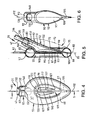
- Fig. 1 is a perspective view of the laryngeal-mask airway device of the present invention being inserted into the throat of a patient;
- Fig. 2 is a side view of the device of Fig. 1 inserted into sealed engagement with the tissue surrounding the laryngeal inlet of the patient;
- Fig. 3 is a posterior perspective view of the device of Fig. 1 removed from the patient, the proximal portions of the airway and inflation tubes being broken away, the back-cushion being cut-away;
- Fig. 4 is an anterior plan view of the device of Fig. 1 removed from the patient, the proximal portions of the airway and inflation tubes being broken away, the indentation on the backplate being shown as hidden;
- Fig. 5 is a cross-sectional view of the device in the plane indicated by line 5-5 of Fig. 4, the proximal portions of the airway and inflation tubes being broken away;
- Fig. 6 is an anterior plan view of the backplate removed from the device shown in Fig. 5;
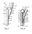
- Fig. 7 is a schematic view of the device in the plane of Fig. 5 showing the present invention, in solid lines, and an airway tube and adjoining portion of the backplate of a prior laryngeal-mask airway device, in broken lines, the proximal portions of the airway and inflation tubes being broken away;
- Fig. 8 is a cross-sectional view of the device in the plane of Fig. 5 showing one of the mask aperture bars of the present invention, in solid lines, and one of the mask aperture bars of a prior laryngeal-mask airway device, in broken lines, the proximal portions of the airway and inflation tubes being broken away;
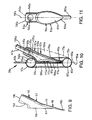
- Fig. 9 is a lateral view of the backplate removed from the device shown in Fig. 5;
- Fig. 10 is a cross-sectional view of a second embodiment of the device of Fig. 1 removed from the patient, the device being shown in the plane of Fig. 5, the proximal portions of the airway and inflation tubes being broken away; and
- Fig. 11 is an anterior plan view of the backplate removed from the device shown in Fig. 10.
- Corresponding reference characters indicate corresponding parts throughout the several views of the drawings.
- As used herein, the anatomical terms "anterior" and "posterior", with respect to the human body, refer to locations nearer to the front of and to the back of the body, respectively, relative to other locations. The term "anterior-posterior (A-P)" refers to a direction, orientation or the like pointing either anteriorly or posteriorly. The anatomical terms "proximal" and "distal", with respect to applying an instrument to the human body, refer to locations nearer to the operator and to the inside of the body, respectively. Alternatively, "distal", as opposed to "proximal", means further away from a given point; in this case, "distal" is used to refer to positions on the LMA-
device 20 or in the body relative to the extreme outer or connector end of the LMA-device. "Proximal" is the opposite of "distal". The term "lateral" refers to a location to the right or left sides of the body, relative to other locations. Alternatively, "lateral" means to one or other side of the mid-line, with respect to the major axis of the body, or to a device lying in the body's major axis. The term "bilateral" refers to locations both to the left and right of the body, relative to the sagittal plane. The term "sagittal" or "sagittally" refers to a vertical longitudinal plane through the center or midline of the body that divides a bilaterally symmetrical body into right and left halves. The sagittal plane is the plane passing antero-posteriorly through the middle of the body in its major axis. The term "medial" means nearer to the mid-line. - A laryngeal-mask airway device (LMA-device) of the present invention, is designated generally by the
reference numeral 20 in Figs. 1 and 2. The LMA-device 20, in a deflated condition, is inserted into thethroat 22 the upper surface of which is bounded by hard andsoft palates device 20 is lodged in thepharynx 30 of thethroat 22 at the base of the hypo-pharynx 32 where the throat divides into the trachea 35 (i.e., windpipe) andoesophagus 37. A lower portion of the LMA-device 20 reaches to the base of the hypo-pharynx 32. After the LMA-device 20 is so lodged in thepharynx 30 such that the lower portion of the LMA-device reaches the base of the hypo-pharynx 32, the LMA-device is inflated. Disposed in the junction between thethroat 22 andtrachea 35 is the flexible epiglottis 40 (i.e., a lid-shaped structure) which forms the upper border of the larynx, entry through which is provided by thelaryngeal inlet 45. - Referring to Figs. 1 and 2, and more particularly to Fig. 3, the laryngeal-mask airway device (LMA-device) 20 is shown comprising an
airway tube 47, installed through themouth 50 of a patient. The LMA-device 20 further comprises abackplate 52 having anairway port 55 through which theairway tube 47 can establish a free externally accessible ventilation passage, via the patient'smouth 50 andthroat 22, and past theepiglottis 40 to the larynx. Thebackplate 52 is preferably of an elastomer such as silicone rubber and relatively stiff, for example, of 80 Shore durometer. - As further shown in Figs. 3 and 4, the
backplate 52 is surrounded by a main-cuff 55 comprising an inflatable ring which, when inflated, has the shape of a torus generated by an asymmetrical oval or ellipse having a widerproximal region 57 and narrowerdistal region 60. The main-cuff 55 is circumferentially united to thebackplate 52 in essentially a single plane. - An externally accessible cuff-
tube 62 and cuff-port 65 on the main-cuff 55 are the means of supplying air to the main-cuff and of extracting air from (and therefore collapsing) the main-cuff for purposes of insertion in or removal from the patient. The check-valve 67 is disposed in the cuff-tube 62 for holding a given inflation or holding a given deflation of the main-cuff 55. - In the installed position of Figs. 1 and 2, the projecting but blunted
distal region 60 of the main-cuff 55 is shaped to conform with the base of the hypo-pharynx 32 where it has established limited entry into the upper sphincteral region of theoesophagus 37. The pharyngeal-side 70 of thebackplate 52 is covered by a thinflexible panel 72, as shown in Figs. 3 and 5, which is peripherally bonded to amargin 75 on the posterior surface of the main-cuff 55, to define an inflatable back-cushion 77 which assures referencing to the posterior wall of thepharynx 30 and thus is able to load the inflated main-cuff 55 forward for enhanced effectiveness of sealing engagement to the tissues surrounding thelaryngeal inlet 45. The inflated main-cuff 55, thus-engaged to thelaryngeal inlet 45, orients a portion of theairway tube 47 including the distal-end 80 at an acute angle to a mid-linemajor plane 82 of the main-cuff 55 and in substantial alignment with the axis of thelaryngeal inlet 45, for direct airway communication only with the larynx. - The
major plane 82 is a plane containing themajor axis 85 of the main-cuff 55 extending between proximal anddistal regions major plane 82 is disposed between, and parallel to, the anterior and posterior surfaces of the main-cuff 55. Additionally, themajor plane 82 is equidistant from the anterior and posterior surfaces of the main-cuff 55. - More specifically, and with particular reference to Fig. 5, the toroidal-shaped main-
cuff 55 is formed by first moulding it in an intermediate stage having opposing edges, each of which has an elliptical shape. The opposing edges of the main-cuff 55, when in generally edge-to-edge relation, are welded together to form aninternal seam 87, as shown in Fig. 5. Theseam 87 defines an oval contained in a plane which is parallel to themajor plane 82, corresponding to the internal surface of the main-cuff 55. - As used herein, the term "welding" describes the bonding together of two components having the same or similar chemical compositions, either by adhesive having the same or similar chemical composition as the components, or by high pressure or temperature fusion, or a combination of any of them.
- The back-
cushion 77, or auxiliary rear cushion, overlies the posterior surface of thebackplate 52, as shown in Fig. 3 and 5. Construction of the back-cushion 77 is described inU.S. Patent 5,355,879 , the contents of which are hereby incorporated by reference herein. - Inflation-air supply to the back-
cushion 77 may be via one or more ports in the main-cuff 55 which provide communication between the interiors of the main-cuff and back-cushion so that both are inflated and deflated together. Alternatively, inflation-air supply to the back-cushion 77 may be via a separate inflating means, such as an inflation tube (not shown), similar to cuff-tube 62, may be provided for the back-cushion so that the back-cushion 77 and main-cuff 55 are separately and independently inflatable and deflatable. - If the main-
cuff 55 and back-cushion 77 are inflated and deflated together, communication between the main-cuff and back-cushion may be facilitated by a separate tube (not shown), preferably with multiple perforations along its length, contained within the main-cuff in communication with the cuff-port 65 such that each perforation communicates with a port between the interiors of the main-cuff and back-cushion 77. Such a separate tube preserves a flowpath between the cuff-port 65 and back-cushion 77 if the main-cuff 55 is completely collapsed from deflation, thereby providing for further deflation of the back-cushion 77 via the cuff-port 65. Alternatively, a channel (not shown) may be formed on the inner surface of the main-cuff 55 between the opening of the cuff-tube 62 into the main-cuff and at least one of the one or more ports between the interiors of the main-cuff and back-cushion 77. Such a channel preserves a flowpath between the cuff-tube 62 and back-cushion 77 if the main-cuff 55 is completely collapsed from deflation. - The
backplate 52 has a one-piece, integral spoon-shape including abowl 90 and an external tube-joint 92 oriented proximally relative to the bowl, as shown in Figs. 5 and 6. Opposite proximal sides of thebowl 90 are defined by a convex pharyngeal-side 95 and concave laryngeal-side 97. Thebowl 90 is relatively shallow in the anterior-posterior direction. Thebowl 90 also has an elongate integral reinforcingdistal rib 105. - The proximal portion of the
bowl 90 sandwiched between the pharyngeal- and laryngeal-sides 95, 97 abuts the posterior surface of theseam 87, as shown in Fig. 5, to attach thebackplate 52 to the main-cuff 55. More specifically, the periphery of the proximal portion of thebowl 90 sandwiched between the pharyngeal- and laryngeal-sides 95, 97 is hermetically bonded to the inner periphery of the main-cuff 55 to establish separation between the laryngeal-chamber region 100 andpharyngeal region 102. Theseam 87 may also be inserted into a corresponding groove in thebowl 90. Alternatively, thebackplate 52 and main-cuff 55 may be extruded as a single, unitary piece. The periphery of thebowl 90 which abuts the inner periphery of the main-cuff 55 defines abowl plane 106 which is parallel to themajor plane 82 of the main-cuff 55. - When the
backplate 52 is attached to the main-cuff 55, thedistal rib 105 pierces the proximal surface of thedistal region 60. The edges of the main-cuff 55 in thedistal region 60 surrounding thedistal rib 105 are hermetically sealed to it such that the enclosure of the main-cuff is defined in part by the distal rib. Thedistal rib 105 extends through the interior of the main-cuff 55 to the distal surface of thedistal region 60. - The
bowl 90 has a longitudinallyelongated airway aperture 107 into which opens abackplate passage 110 extending through the tube-joint 92. Theairway aperture 107 has a major axis 111 which is contained in thesagittal plane 112. - Two mask aperture bars (MABs) 115, 117 extend longitudinally and anteriorly of the
airway aperture 107, as shown in Fig. 4. TheMABs sagittal plane 112 and symmetrical relative to the plane. TheMABs 115, I 17 each have aproximal end side 97 of thebowl 90 proximally of theairway aperture 107. Additionally, theMABs distal end side 97 of thebowl 90 distally of the airway aperture. - The
MABs 115, 177 may be defined by a portion of a continuous layer of elastomer, integral with the main-cuff 55, which overlies the laryngeal-side 97. The elastomer layer has an opening the periphery of which is outward of theairway aperture 107. The opening is longitudinally traversed by theMABs - The distal ends 125, 127 of the
MABs bowl 90 generally near the longitudinal mid-point of the laryngeal-side 97, or distally of it. This results in eachMAB angle 118 with thebowl plane 106 which is less than the corresponding angle between the MAB P1 of a prior LMA-device, as shown in Fig. 8. The relatively shallowness of thebowl 90 in the anterior-posterior direction further results in theangle 118 being more acute. A preferred angular displacement of theangle 118 is between 7 and 12 degrees, and may preferably be 9 degrees. - The elongate tube-joint 92 is formed on the pharyngeal-side 95 and extends posteriorly and proximally relative to the
bowl 90. The tube-joint 92 has aproximal end 130 from which thebackplate passage 110 extends to theairway aperture 107 in the laryngeal-side 97. Thebackplate passage 110 has a longitudinalcentral axis 132 contained in thesagittal plane 112. At theproximal end 130, thebackplate passage 110 has an elliptical cross section with amajor axis 135 oriented in perpendicular relation to thesagittal plane 112. Themajor axis 135 is therefore transverse to the major axis 111 of theairway aperture 107. This differing orientation of themajor axes 111, 132 of thebackplate passage 110 is accomplished by a smooth transition in the cross-sectional shape of the backplate passage along its length. - The tube-joint 92, and the
central axis 132 of thebackplate passage 110 are inclined posteriorly in thesagittal plane 112 relative to a plane containing the periphery of thebowl 90. In the embodiment shown in Fig. 5, the inclination of the tube-joint 92 may be defined by a tube-joint axis 136 which is perpendicular to the cross-section of theproximal end 130 and which coincides with thecentral axis 132 at its intersection with the cross-section of theproximal end 130. The inclination of the tube-joint 92 may be further defined by anangle 137 between the tube-joint axis 136 andbowl plane 106. A preferred angular displacement of theangle 137 is between 5 and 10 degrees, and may preferably be 7 degrees. The inclination of the tube-joint 92, defined by theangle 137, is less than the corresponding angle defined by the inclination of a tube-joint P2 of a prior-LMA, as shown in Fig. 7. - The anterior surface of the tube-joint 92 has an
indentation 140, as shown in Figs. 4, 5, 6 and 9. As shown in Fig. 5, theindentation 140 is in the thick wall region of the tube-joint 92 resulting in the advantage of increasing the flexibility of the tube-joint. Theindentation 140 may be occupied by the main-cuff 55 when the main-cuff is inflated, as shown in Fig. 5. Theindentation 140 may also be formed closer to theproximal end 130, such as is shown in Fig. 1. Alternatively, the proximal portion of theindentation 140 may be formed across the boundary between the tube-joint 92 andairway tube 47 such that portions of the indentation are in both the airway tube and tube-joint. Also, theentire indentation 140 may be formed in theairway tube 47 adjacent to its connection to the tube-joint 92. - The
backplate 52, main-cuff 55 and back-cushion 77 of LMA-devices 20 are generally manufactured by molding techniques from suitably soft and compliant rubber materials. Thebackplate 52 and inflatable main-cuff 55 may be formed as a one piece molding by molds and molding techniques such as are described, for example, inU.S. Patent 5,305,743 , the contents of which are hereby incorporated herein. Thebackplate 52 is formed to have a greater thickness than the walls of the main-cuff 55 to provide the LMA-device 20 with a degree of rigidity while still allowing it to have an overall soft and flexible nature. The main-cuff 55 has a thin-walled construction and the reinforcingdistal rib 105 has an intermediate thickness and compliancy. - As shown in Figs. 4 and 5, the portion of the
airway tube 47 containing thedistal end 80 is supported in thebackplate passage 110 of the tube-joint 92 in communication with theairway aperture 107 in the laryngeal-side 97. Such communication provides a flowpath between theairway tube 47 and laryngeal-chamber region 100. Theairway tube 47 is connected to the tube-joint 92 by welding using an adhesive or, alternatively, connected by high-pressure or temperature fusion. - Fig. 10 shows a second embodiment of the
backplate 52a. Parts in Fig. 10 having corresponding parts in Figs. 5 and 6 have the same reference numeral with the addition of suffix a. Thebackplate 52a is similar to thebackplate 52 illustrated in Figs. 5 and 6 except that thedistal rib 105a of thebackplate 52a is applied to the posterior surface of thedistal region 60a of the main-cuff 55a, as shown in Fig. 10. Thedistal rib 105a has a concave anterior surface corresponding to the adjoining convex posterior surface of thedistal region 60a thereby limiting the radial clearance between the distal region andend distal rib 105a does not pierce the posterior surface of thedistal region 60a, in contrast to the embodiment shown in Fig. 5, and is therefore separated from the interior of the main-cuff 55a. Thedistal rib 105a may be effectively constituted by a thickening of the posterior wall of thedistal region 60a of the inflatable main-cuff 55a and, as shown, forms a distal extension of thebowl 90a of thebackplate 52a. Thedistal rib 105a has a downturned profile by being incorporated into the posterior surface of the main-cuff 55a. The distal end of thedistal rib 105a is spatulate. - Insertion of the LMA-
device 20 into the patient'sthroat 22 is illustrated in Fig. 1, and is done preferably with the patient in a supine orientation and the head 142 of the patient tilted backwards and supported from below by the left hand 145 of the anaesthetist. The right index finger 147 and thumb 150 of the anesthetist gently grasps theflexible airway tube 47 of the LMA-device 20. The right index finger 147 is located at the junction of theairway tube 47 and the main-cuff 55 to gently urge the LMA-device 29 with its down-turned deflated main-cuff into the patient'sthroat 22. As shown in Fig. 1, theindentation 140 provides a locator for the right index finger 147 of the anaesthetist during insertion of the LMA-device 20 into thethroat 22 of the patient. When the LMA-device 20 is properly positioned across the patient'slaryngeal inlet 45, the main-cuff 55 is gently inflated throughcuff tube 62 to form an airway seal around the laryngeal inlet and establish a closed airway to the patient's lungs. The LMA-device 20 so positioned, with the main-cuff 55 fully inflated, is shown in Fig. 2. The thin-walled construction of the main-cuff 55 enables it, when inflated, to present to the tissues surrounding the laryngeal inlet 45 a softly compliant sealing surface. - As shown in Fig. 1, the
distal region 60 of the fully deflated main-cuff 55 is the leading end of the LMA-device 20 when inserting the LMA-device into the patient'sthroat 22. Careful insertion of the LMA-device 20 into the patient'sthroat 22 is required to prevent thedistal region 60 from folding over onto itself because the distal region is formed of a soft and flexible material which facilitates such folding over. Such folding over is obstructed by the reinforcingdistal rib 105 within thedistal region 60 of the inflatable main-cuff 55. The intermediate thickness and compliancy of the reinforcingdistal rib 105 allows it to follow the contours of the posterior surface of the inflated main-cuff 55, thereby to urge the deflated main-cuff into the desired downturned orientation and to enable the LMA-device 20 present a distal end to the tissues of thethroat 22 which is sufficiently pliable to avoid undesirable contact with the throat during its insertion but sufficiently rigid to prevent it from being readily folded over on itself during such a procedure. As shown in Figs. 3 and 4, thedistal rib 105 is not readily visible when the main-cuff 55 is either deflated or inflated since it is contained within thedistal region 60. - In the embodiment shown in Fig. 10, the downturned profile the
distal rib 105a helps to facilitate adoption by the main-cuff 55a of the desired downturned orientation when it is fully deflated. Thedistal rib 105a may not be readily visible because it may appear to blend in with the posterior wall of thedistal region 60. The spatulate of the distal portion of thedistal rib 105a does not present any sharp edges or corners to thethroat 22 the patient during insertion of the LMA-device 20 which is desirable as striking of thethroat 22 by sharp edges or corners is normally to be avoided. - The
acute angle 118 between theMABs bowl plane 106 results in the MABs presenting a substantially less gradient to the patient'sepiglottis 40 than theMABs P 1 of a prior-LMA, as shown in Fig. 8. TheMABs epiglottis 40 slides when thebackplate 52 and the attached main-cuff 55 enter thepharynx 30. If the MABs are sufficiently posterior of theepiglottis 40, e.g., MAB P1, such sliding contact may result in the proximal end of theepiglottis 40 folding over posteriorly such that it becomes sandwiched between the base of the epiglottis and the MABs possibly obstructing theairway aperture 107. The likelihood of such posterior folding over of theepiglottis 40 is substantially reduced by theMABs MABs side 97 is increased thereby anteriorly propping the epiglottis to limit further anterior displacement necessary to accommodate the posterior folding. Further reduction in the likelihood of an obstruction is provided by the increased A-P clearance between theMABs side 97, which in turn provides increased A-P clearance between theepiglottis 40 andairway aperture 107 contained in the laryngeal-side. - When the main-
cuff 55 andbackplate 52 are installed in thepharynx 30 such that main-cuff is sealed against the tissues surrounding the patient'slaryngeal inlet 45, the reducedangle 137 between the tube-joint axis 136 andbowl plane 106, relative to the corresponding force resulting from tube-joint P2, reduces the force exerted by the tube-joint 92 andairway tube 47 against the posterior surface of thethroat 22. Any force against the tissues of thethroat 22 should normally be limited. - The reduction in the force exerted by the tube-joint 92 and
airway tube 47 against the posterior surface of thethroat 22 may result in a reduction in the reaction force of the main-cuff 55 against the tissues surrounding the patient'slaryngeal inlet 45 which, in turn, may reduce the tightness of the seal between the main-cuff and tissues. Any such reduction in the seal is compensated for the inflatable back-cushion 77 which gently urges thebackplate 52 and main-cuff 55 anteriorly against the tissues surrounding the patient'slaryngeal inlet 45 in order to reinforce the seal between the inflated main-cuff and the tissues. - Additionally, the inflatable back-
cushion 77 presents a more softly complaint surface to the posterior surface of the patient'sthroat 22. Also, the back-cushion 77 enables the main-cuff 55 to be inflated at a lower pressure, i.e., typically 60 cm H2O, as compared to the inflation pressure required of the main-cuff if the LMA-device 20 does not include a back-cushion 77. Reducing the inflation pressure of the main-cuff 55 enables a reduced wall thickness of the main-cuff.
Claims (5)
- A laryngeal-mask airway device comprising a flexible airway tube and a mask attached to one end of the airway tube, the mask having a generally elliptical periphery provided with an inflatable cuff which surrounds the hollow interior of the mask into which the airway tube opens, the device including a reinforcing rib incorporated into the distal end of the inflatable cuff.
- A laryngeal-mask airway device as set forth in claim 1, wherein the mask comprises a backplate, the backplate and cuff being formed as a one piece molding.
- A laryngeal-mask airway device as set forth in claim 1 or claim 2, wherein said rib extends into and through the interior of the distal end of said cuff.
- A laryngeal-mask airway device as set forth in claim 3, wherein said rib has a distal tip which contacts the distal tip of said cuff.
- A laryngeal-mask airway device as set forth in claim 1, wherein said rib is seated on the anterior surface of the distal region of said cuff.
Applications Claiming Priority (3)
| Application Number | Priority Date | Filing Date | Title |
|---|---|---|---|
| GBGB9821771.4A GB9821771D0 (en) | 1998-10-06 | 1998-10-06 | Improvements relating to laryngeal mask airway devices |
| EP99947765A EP1119386B1 (en) | 1998-10-06 | 1999-10-06 | Laryngeal mask airway device |
| EP05019292A EP1600192A3 (en) | 1998-10-06 | 1999-10-06 | Laryngeal mask airway device |
Related Parent Applications (1)
| Application Number | Title | Priority Date | Filing Date |
|---|---|---|---|
| EP05019292A Division EP1600192A3 (en) | 1998-10-06 | 1999-10-06 | Laryngeal mask airway device |
Publications (2)
| Publication Number | Publication Date |
|---|---|
| EP1839696A2 true EP1839696A2 (en) | 2007-10-03 |
| EP1839696A3 EP1839696A3 (en) | 2009-11-18 |
Family
ID=10840092
Family Applications (4)
| Application Number | Title | Priority Date | Filing Date |
|---|---|---|---|
| EP05019293A Withdrawn EP1609497A3 (en) | 1998-10-06 | 1999-10-06 | Laryngeal mask airway device |
| EP99947765A Revoked EP1119386B1 (en) | 1998-10-06 | 1999-10-06 | Laryngeal mask airway device |
| EP07011947A Withdrawn EP1839696A3 (en) | 1998-10-06 | 1999-10-06 | Laryngeal mask airway device |
| EP05019292A Withdrawn EP1600192A3 (en) | 1998-10-06 | 1999-10-06 | Laryngeal mask airway device |
Family Applications Before (2)
| Application Number | Title | Priority Date | Filing Date |
|---|---|---|---|
| EP05019293A Withdrawn EP1609497A3 (en) | 1998-10-06 | 1999-10-06 | Laryngeal mask airway device |
| EP99947765A Revoked EP1119386B1 (en) | 1998-10-06 | 1999-10-06 | Laryngeal mask airway device |
Family Applications After (1)
| Application Number | Title | Priority Date | Filing Date |
|---|---|---|---|
| EP05019292A Withdrawn EP1600192A3 (en) | 1998-10-06 | 1999-10-06 | Laryngeal mask airway device |
Country Status (11)
| Country | Link |
|---|---|
| US (4) | US7156100B1 (en) |
| EP (4) | EP1609497A3 (en) |
| AT (1) | ATE303839T1 (en) |
| AU (1) | AU6113399A (en) |
| CA (4) | CA2650214C (en) |
| DE (2) | DE69927167T2 (en) |
| DK (1) | DK1119386T3 (en) |
| ES (1) | ES2252977T3 (en) |
| GB (1) | GB9821771D0 (en) |
| HK (1) | HK1037985A1 (en) |
| WO (1) | WO2000020062A2 (en) |
Families Citing this family (60)
| Publication number | Priority date | Publication date | Assignee | Title |
|---|---|---|---|---|
| US5878745A (en) * | 1996-03-01 | 1999-03-09 | Brain; Archibald I.J. | Gastro-laryngeal mask |
| US8631796B2 (en) * | 1997-04-10 | 2014-01-21 | Cookgas, L.L.C. | Laryngeal mask |
| US7331346B2 (en) * | 1997-12-24 | 2008-02-19 | Indian Ocean Medical, Inc. | Monitoring and control for a laryngeal mask airway device |
| GB9727367D0 (en) * | 1997-12-24 | 1998-02-25 | Brain Archibald Ian Jeremy | Improvements in laryngeal mask airway devices |
| GB9817537D0 (en) * | 1998-08-13 | 1998-10-07 | Brain Archibald Ian Jeremy | A laryngear mask airway with mutually independant laterally-placed ultra-flexible eastric access/discharge and airway tubes |
| GB9821771D0 (en) * | 1998-10-06 | 1998-12-02 | Brain Archibald Ian Jeremy | Improvements relating to laryngeal mask airway devices |
| EA002847B1 (en) † | 1999-04-09 | 2002-10-31 | Арчибальд Ян Джереми Брэйн | Disposable laryngeal mask airway device |
| GB9920098D0 (en) * | 1999-08-26 | 1999-10-27 | Smiths Industries Plc | Medico-surgical apparatus |
| US7159589B2 (en) | 2001-08-23 | 2007-01-09 | Indian Ocean Medical Inc. | Disposable laryngeal mask airway device |
| US6705322B2 (en) * | 2002-03-11 | 2004-03-16 | Ti-Li Chang | Laryngeal mask airway |
| GB0218868D0 (en) | 2002-08-14 | 2002-09-25 | Nasir Muhammed A | Improved airway management device |
| US7147627B2 (en) * | 2002-08-21 | 2006-12-12 | Hollister Incorporated | Bowel management system |
| US6792948B2 (en) | 2003-01-22 | 2004-09-21 | Archibald I. J. Brain | Laryngeal mask airway device with airway tube having flattened outer circumference and elliptical inner airway passage |
| CA2535849C (en) | 2003-08-14 | 2013-03-26 | Muhammed Aslam Nasir | Improved airway device |
| US8016816B2 (en) | 2003-09-09 | 2011-09-13 | Convatec Technologies Inc. | Fecal management appliance and method and apparatus for introducing same |
| GB0510951D0 (en) | 2005-05-27 | 2005-07-06 | Laryngeal Mask Company The Ltd | Laryngeal mask airway device |
| ITMO20050210A1 (en) * | 2005-08-05 | 2007-02-06 | Hs Hospital Service Spa | TRACHEOTOMY DEVICE |
| GB2444779A (en) | 2006-12-14 | 2008-06-18 | Archibald Ian Jeremy Brain | A laryngeal mask with with drug delivery means |
| US8495999B2 (en) | 2007-08-04 | 2013-07-30 | John Adam Law | Airway intubation device |
| FR2921840B1 (en) * | 2007-10-08 | 2011-04-29 | Georges Boussignac | RESPIRATORY ASSISTANCE DEVICE |
| GB2454199A (en) * | 2007-10-30 | 2009-05-06 | Laryngeal Mask Co Ltd | Laryngeal mask with tape tab |
| CN105483686B (en) * | 2008-05-19 | 2019-02-15 | 汉高股份及两合公司 | The thin inorganic corrosion protective coating of alkalescent for metal base |
| GB0810169D0 (en) | 2008-06-04 | 2008-07-09 | Cosmeplast Ets | Improvements relating to respiratory interface devices |
| GB0821291D0 (en) * | 2008-11-21 | 2008-12-31 | Nasir Muhammed A | Improved airway device |
| CH699987A1 (en) | 2008-11-27 | 2010-05-31 | Deltona Innovations Ag | Laryngeal mask with a nozzle. |
| CH699986A1 (en) * | 2008-11-27 | 2010-05-31 | Deltona Innovations Ag | Laryngeal Mask with Oesophagealdurchgang. |
| CH699985A1 (en) * | 2008-11-27 | 2010-05-31 | Deltona Innovations Ag | Supraglottic tube for introducing laryngeal mask, has guiding unit mounted on guide lumen for modifying curvature radius of tube, where guiding unit includes pressure member and flexible traction member |
| GB0903654D0 (en) | 2009-03-03 | 2009-04-15 | Laryngeal Mask Company The Ltd | Artificial airway device |
| JP5938773B2 (en) | 2009-07-06 | 2016-06-22 | テレフレックス・ライフ・サイエンシーズTeleflex Life Sciences | Artificial airway |
| USD665495S1 (en) * | 2009-07-14 | 2012-08-14 | Muhammed Aslam Nasir | Medical device |
| AU2010282221B2 (en) | 2009-08-13 | 2015-02-05 | Teleflex Life Sciences Llc | Pressure indicator |
| US9854962B2 (en) * | 2009-11-30 | 2018-01-02 | King Systems Corporation | Visualization instrument |
| US20110152794A1 (en) * | 2009-12-17 | 2011-06-23 | Carver Alan R | Throat obstruction dislodging device and method for its use |
| GB201010647D0 (en) | 2010-06-24 | 2010-08-11 | Docsinnovent Ltd | Stopper device |
| GB201016562D0 (en) | 2010-10-01 | 2010-11-17 | Laryngeal Mask Company The Ltd | Artificial airway device |
| US9675772B2 (en) | 2010-10-15 | 2017-06-13 | The Laryngeal Mask Company Limited | Artificial airway device |
| AU2011327848C1 (en) | 2010-11-12 | 2016-10-20 | Teleflex Medical Incorporated | Atomizer for nasal therapy |
| JP6242687B2 (en) * | 2011-02-02 | 2017-12-06 | ウメダス、リミテッドUmedaes Limited | Improved artificial airway |
| USD688787S1 (en) | 2011-06-08 | 2013-08-27 | Intersurgical Ag | Airway device cap and strap holder |
| USD693920S1 (en) | 2011-06-08 | 2013-11-19 | Intersurgical Ag | Airway device |
| USD665254S1 (en) | 2011-06-08 | 2012-08-14 | Intersurgical Ag | Airway device packaging |
| GB2492357B (en) * | 2011-06-28 | 2014-09-10 | Breslauer Ltd | Improved laryngeal mask assembly |
| USD712244S1 (en) | 2011-09-23 | 2014-09-02 | Intersurgical Ag | Medical device package |
| GB201120628D0 (en) | 2011-11-30 | 2012-01-11 | Laryngeal Mask Company The Ltd | Endoscopy device |
| US11135385B2 (en) | 2012-01-10 | 2021-10-05 | Samreen Mehar Ali | Neonatal laryngeal mask airway |
| GB201201438D0 (en) | 2012-01-27 | 2012-03-14 | Docsinnovent Ltd | Improved stopper device |
| USD761952S1 (en) | 2012-07-27 | 2016-07-19 | Docsinnovent Limited | Airway device |
| US20150283346A1 (en) * | 2012-10-30 | 2015-10-08 | Breslauer Ltd. | Intumask assembly |
| CN202961406U (en) * | 2012-11-08 | 2013-06-05 | 天津美迪斯医疗用品有限公司 | Proseal laryngeal mask airway provided with finger stall-type auxiliary inserter |
| GB201314631D0 (en) | 2013-08-15 | 2013-10-02 | Teleflex Life Sciences | Endoscopy device |
| GB2555360B (en) | 2013-12-17 | 2018-10-10 | Intersurgical Ag | Intubating Airway Device |
| SG2014011720A (en) | 2014-02-10 | 2015-09-29 | Craig Wight Ronald | An airway management device and method of manufacture |
| USD842456S1 (en) | 2015-12-15 | 2019-03-05 | Intersurgical Ag | Airway device |
| AU201714823S (en) | 2017-02-27 | 2017-10-12 | Teleflex Life Sciences Unlimited Co | Laryngeal mask airway device |
| US10314995B2 (en) | 2017-08-17 | 2019-06-11 | Yang Sun | Endotracheal intubation and supraglottic airway device |
| US10213567B1 (en) | 2017-11-08 | 2019-02-26 | Shan Theventhiran | Easily removable intubating LMA |
| GB201720733D0 (en) | 2017-12-13 | 2018-01-24 | Ashkal Development Ltd | Airway device |
| US10653307B2 (en) * | 2018-10-10 | 2020-05-19 | Wm & Dg, Inc. | Medical devices for airway management and methods of placement |
| US11497394B2 (en) | 2020-10-12 | 2022-11-15 | Wm & Dg, Inc. | Laryngoscope and intubation methods |
| CN113332552A (en) * | 2021-06-17 | 2021-09-03 | 复旦大学附属眼耳鼻喉科医院 | High leakproofness laryngeal mask |
Citations (2)
| Publication number | Priority date | Publication date | Assignee | Title |
|---|---|---|---|---|
| US5632271A (en) * | 1996-03-22 | 1997-05-27 | Brain; Archibald I. J. | Laryngeal mask with gastric-drainage feature |
| GB2323534A (en) * | 1997-03-27 | 1998-09-30 | Smiths Industries Plc | Endotracheal tube guide |
Family Cites Families (158)
| Publication number | Priority date | Publication date | Assignee | Title |
|---|---|---|---|---|
| US2862498A (en) | 1957-06-14 | 1958-12-02 | Don J Weekes | Endotracheal tube |
| US3529596A (en) | 1968-04-03 | 1970-09-22 | Charles G Garner | Automatic intermittent tracheotomy tube cuff inflator-deflator |
| US3554673A (en) | 1969-01-31 | 1971-01-12 | Sage Instr Inc | Syringe pump |
| US3683908A (en) * | 1969-10-20 | 1972-08-15 | Tantrimudalige Anthony Don Mic | Apparatus for sealing the oesophagus and providing artificial respiration |
| US3794036A (en) * | 1972-08-02 | 1974-02-26 | R Carroll | Pressure regulated inflatable cuff for an endotracheal or tracheostomy tube |
| US4104357A (en) * | 1973-01-10 | 1978-08-01 | Monster Molding, Inc. | Method of rotational molding about plural axes at low rotational speeds |
| US3931822A (en) * | 1974-02-26 | 1976-01-13 | Marici Frank N | Automatic alternating cuff endo tracheal tube inflator |
| FR2298147A1 (en) * | 1975-01-17 | 1976-08-13 | Ucc Union Chimique Cont | DEVICE GIVING THE ALARM IN CASE OF DISCONNECTION OF A HOSE, IN PARTICULAR OF A RESPIRATOR |
| US4116201A (en) | 1976-12-20 | 1978-09-26 | The Kendall Company | Catheter with inflation control device |
| US4134407A (en) * | 1977-03-25 | 1979-01-16 | Elam James O | External pressure-volume monitor for endotracheal cuff |
| US4159722A (en) * | 1977-03-28 | 1979-07-03 | Sherwood Medical Industries, Inc. | Pressure regulator for endotracheal tube cuff or the like |
| US4178938A (en) | 1977-06-24 | 1979-12-18 | Au Anthony S | Pressure control systems |
| US4178940A (en) | 1977-06-24 | 1979-12-18 | Au Anthony S | Pressure control systems |
| US4231365A (en) | 1978-01-30 | 1980-11-04 | Scarberry Eugene N | Emergency resuscitation apparatus |
| US4351330A (en) | 1978-01-30 | 1982-09-28 | Scarberry Eugene N | Emergency internal defibrillation |
| US4285340A (en) * | 1979-03-16 | 1981-08-25 | Gezari Walter A | Apparatus for controlling the pressure in a tracheal cuff |
| US4256099A (en) * | 1979-03-21 | 1981-03-17 | Dryden Gale E | Two-tube resuscitation system |
| JPS5667383A (en) * | 1979-11-08 | 1981-06-06 | Mitsui Petrochem Ind Ltd | Thixotropic agent |
| GB2111394B (en) | 1981-12-16 | 1985-09-11 | Archibald Ian Jeremy Brain | Artificial airway device |
| US4471775A (en) | 1982-09-07 | 1984-09-18 | Clair Michael W | Endotracheal tube cuff synchronizing system |
| US4501273A (en) * | 1982-09-30 | 1985-02-26 | Mcginnis Gerald E | Endotracheal tube with pressure controlled inflatable cuff |
| US4526196A (en) * | 1983-01-26 | 1985-07-02 | Nayan S. Shah | Gas pressure measuring and regulating device and method |
| US4583917A (en) * | 1983-06-17 | 1986-04-22 | Shah Nayan S | Pressure regulating and monitoring device |
| DE3327342A1 (en) | 1983-07-29 | 1985-02-07 | Peter 7800 Freiburg Pedersen | DEVICE FOR DETECTING AND EVALUATING THE PRESSURE IN THE BALLOON CUFF OF A CLOSED TRACHEAL TUBE |
| US4553540A (en) | 1983-08-16 | 1985-11-19 | Straith Richard E | Airway |
| US4689041A (en) * | 1984-01-20 | 1987-08-25 | Eliot Corday | Retrograde delivery of pharmacologic and diagnostic agents via venous circulation |
| JPS628766A (en) | 1985-07-03 | 1987-01-16 | 鳥取大学長 | Cuff pressure controller of gas insert tube with cuff |
| US4793327A (en) | 1986-01-21 | 1988-12-27 | Frankel Alfred R | Device for opening a patient's airway during automatic intubation of the trachea |
| JPS62186872A (en) * | 1986-02-14 | 1987-08-15 | 鳥取大学長 | Respiration pressure superposing type cuff pressure adjusting apparatus |
| US4848331A (en) * | 1986-11-14 | 1989-07-18 | Northway Meyer Robert | Apparatus and method for pulmonary ventilation of a patient concurrent with fiberoptic respiratory tract examination and tracheal intubation |
| US5042469A (en) * | 1987-03-24 | 1991-08-27 | Augustine Medical, Inc. | Tracheal intubation guide |
| US5203320A (en) * | 1987-03-24 | 1993-04-20 | Augustine Medical, Inc. | Tracheal intubation guide |
| US4832020A (en) * | 1987-03-24 | 1989-05-23 | Augustine Scott D | Tracheal intubation guide |
| GB2205499B (en) | 1987-06-05 | 1991-01-16 | Archibald Ian Jeremy Brain | Artificial airway device |
| US4924862A (en) * | 1987-08-19 | 1990-05-15 | Gary Levinson | Pressure controller and leak detector for tracheal tube cuff |
| US4850349A (en) * | 1987-12-04 | 1989-07-25 | Farahany Amir H | Endotracheal tube sealing cuff system |
| US4872483A (en) | 1987-12-31 | 1989-10-10 | International Medical Products, Inc. | Conveniently hand held self-contained electronic manometer and pressure modulating device |
| US4856510A (en) * | 1988-04-06 | 1989-08-15 | Kowalewski Ryszard J | Tracheal tube inflator |
| US4953547A (en) | 1989-01-26 | 1990-09-04 | Poole Jr Samuel E | Drug administering endotracheal respiration systems |
| GB2229367A (en) | 1989-03-22 | 1990-09-26 | Archibald Ian Jeremy Brain | Artificial airway device |
| US5169379A (en) | 1989-06-14 | 1992-12-08 | L-Vad Technology | In-series ventricular assist system and method of controlling same |
| US4981470A (en) * | 1989-06-21 | 1991-01-01 | Synectics Medical, Inc. | Intraesophageal catheter with pH sensor |
| US5042476A (en) * | 1989-08-10 | 1991-08-27 | Smith Charles A | Endotracheal tube protection arrangement |
| WO1991003207A1 (en) | 1989-09-08 | 1991-03-21 | Boston Scientific Corporation | Physiologic low stress angioplasty |
| US5038766A (en) | 1989-11-08 | 1991-08-13 | Parker Jeffrey D | Blind orolaryngeal and oroesophageal guiding and aiming device |
| US5174283A (en) | 1989-11-08 | 1992-12-29 | Parker Jeffrey D | Blind orolaryngeal and oroesophageal guiding and aiming device |
| GB9003857D0 (en) | 1990-02-21 | 1990-04-18 | Smiths Industries Plc | Medico-surgical tube assemblies |
| GB9026403D0 (en) * | 1990-12-05 | 1991-01-23 | Smiths Industries Plc | Pressure monitors |
| GB9102821D0 (en) | 1991-02-11 | 1991-03-27 | Brain Archibald Ian Jeremy | An intubating laryngeal mask airway |
| US5339808A (en) | 1991-04-02 | 1994-08-23 | Don Michael T Anthony | Endotracheal-esophageal intubation devices |
| US5235973A (en) * | 1991-05-15 | 1993-08-17 | Gary Levinson | Tracheal tube cuff inflation control and monitoring system |
| US5795325A (en) * | 1991-07-16 | 1998-08-18 | Heartport, Inc. | Methods and apparatus for anchoring an occluding member |
| GB9119703D0 (en) * | 1991-09-14 | 1991-10-30 | Dingley John | Medico-surgical device |
| GB9204754D0 (en) | 1992-03-05 | 1992-04-15 | Brain Archibald Ian Jeremy | Mould for manufacture of a laryngeal mask |
| MX9301163A (en) | 1992-03-05 | 1994-07-29 | Brain Archibald Ian Jeremy | LARINGEA MASK AND METHOD FOR ITS MANUFACTURE. |
| US5273537A (en) | 1992-03-06 | 1993-12-28 | Scimed Life Systems, Inc. | Power-assisted inflation apparatus |
| US5421325A (en) * | 1992-04-30 | 1995-06-06 | Cinberg; James Z. | Endotracheal tube assembly and related method |
| US5546936A (en) * | 1992-05-19 | 1996-08-20 | Mallinckrodt Medical, Inc. | Tracheal tube with reinforced flexible segment |
| US5241956A (en) | 1992-05-21 | 1993-09-07 | Brain Archibald Ian Jeremy | Laryngeal mask airway with concentric drainage of oesophagus discharge |
| US5249571A (en) | 1992-05-21 | 1993-10-05 | Brain Archibald Ian Jeremy | Laryngeal clamp airway |
| DE4222220A1 (en) | 1992-07-07 | 1994-01-13 | Deutsche Aerospace | Procedure for measuring and regulating the pressure in the sealing sleeve of a tracheal tube |
| GB9215455D0 (en) | 1992-07-21 | 1992-09-02 | Brain Archibald Ian Jeremy | A laryngeal mask airway adapted to carry a reflecting-type oximeter |
| EP0580385B1 (en) | 1992-07-21 | 1996-05-08 | Archibald Ian Jeremy Dr. Brain | Laryngeal mask incorporating a reflectance oximeter |
| US5297547A (en) * | 1992-07-30 | 1994-03-29 | Brain Archibald Ian Jeremy | Laryngeal mask construction |
| ZA927931B (en) * | 1992-08-24 | 1994-04-14 | Donald Munro Miller | Breathing apparatus |
| US5355879A (en) | 1992-09-28 | 1994-10-18 | Brain Archibald Ian Jeremy | Laryngeal-mask construction |
| US5400771A (en) * | 1993-01-21 | 1995-03-28 | Pirak; Leon | Endotracheal intubation assembly and related method |
| US5331967A (en) * | 1993-02-05 | 1994-07-26 | Playa De Los Vivos S.A. | Tracheal intubation monitoring apparatus and method |
| US5546935A (en) * | 1993-03-09 | 1996-08-20 | Medamicus, Inc. | Endotracheal tube mounted pressure transducer |
| GB9312131D0 (en) * | 1993-06-11 | 1993-07-28 | Blatchford & Sons Ltd | Prosthesis control system |
| FR2709251B1 (en) | 1993-08-26 | 1995-11-10 | Georges Boussignac | Breathing assistance tube. |
| US5443063A (en) | 1993-08-31 | 1995-08-22 | The Johns Hopkins University | Cuffed oro-pharyngeal airway |
| US5551420A (en) | 1993-11-09 | 1996-09-03 | Cprx, Inc. | CPR device and method with structure for increasing the duration and magnitude of negative intrathoracic pressures |
| US6062219A (en) * | 1993-11-09 | 2000-05-16 | Cprx Llc | Apparatus and methods for assisting cardiopulmonary resuscitation |
| US5692498A (en) | 1993-11-09 | 1997-12-02 | Cprx, Inc. | CPR device having valve for increasing the duration and magnitude of negative intrathoracic pressures |
| US5599301A (en) | 1993-11-22 | 1997-02-04 | Advanced Cardiovascular Systems, Inc. | Motor control system for an automatic catheter inflation system |
| US5459700A (en) | 1993-11-22 | 1995-10-17 | Advanced Cardiovascular Systems, Inc. | Manual timer control for inflation device |
| US5554673A (en) | 1993-11-29 | 1996-09-10 | Polygenex International, Inc. | Dip molded polyurethane film compositions |
| GB2285765B (en) | 1994-01-12 | 1997-10-29 | Archibald Ian Jeremy Brain | Forming tool for use with a laryngeal mask |
| US5529582A (en) | 1994-02-01 | 1996-06-25 | Fukuhara; Tomio | Apparatus for inserting laryngeal mask |
| US5582167A (en) | 1994-03-02 | 1996-12-10 | Thomas Jefferson University | Methods and apparatus for reducing tracheal infection using subglottic irrigation, drainage and servoregulation of endotracheal tube cuff pressure |
| JP3782123B2 (en) * | 1994-05-31 | 2006-06-07 | 住友ベークライト株式会社 | Pharyngeal airway |
| GB9411215D0 (en) | 1994-06-04 | 1994-07-27 | Brain Archibald Ian Jeremy | A fibreoptic intubating laryngeal mask airway |
| SE503155C2 (en) * | 1994-07-28 | 1996-04-01 | Comasec International Sa | Methods and apparatus for functional control of breathing apparatus |
| US5569219A (en) | 1994-09-13 | 1996-10-29 | Hakki; A-Hamid | Collapsible catheter |
| GB9422224D0 (en) | 1994-11-03 | 1994-12-21 | Brain Archibald Ian Jeremy | A laryngeal mask airway device modified to detect and/or stimulate mescle or nerve activity |
| US5577693A (en) | 1995-01-11 | 1996-11-26 | Children's Medical Center Corporation | Anesthesia circuit stand |
| US5477851A (en) | 1995-01-26 | 1995-12-26 | Callaghan; Eric B. | Laryngeal mask assembly and method for removing same |
| GB9504657D0 (en) | 1995-03-08 | 1995-04-26 | Neil Michael J O | An improved artificial airway device |
| GB9505134D0 (en) | 1995-03-14 | 1995-05-03 | Smiths Industries Plc | Laryngeal mask airways |
| GB2298797B (en) | 1995-03-14 | 1998-12-09 | Smiths Industries Plc | Laryngeal mask airways |
| GB9505399D0 (en) | 1995-03-17 | 1995-05-03 | Smiths Industries Plc | Medico-surgical devices |
| GB9513860D0 (en) | 1995-07-07 | 1995-09-06 | Smiths Industries Plc | Securing devices |
| AUPN417395A0 (en) | 1995-07-14 | 1995-08-10 | Techbase Pty. Ltd. | An improved spacer |
| AUPN538495A0 (en) * | 1995-09-12 | 1995-10-05 | Esnouf, Philip Stuart | Disposable oxygenating device |
| MY138519A (en) | 1995-10-03 | 2009-06-30 | Indian Ocean Medical Inc | Artificial airway device |
| MY115052A (en) | 1995-10-03 | 2003-03-31 | Archibald Ian Jeremy Brain | Laryngeal mask airway incorporating an epiglottic elevating mechanism |
| US5791341A (en) | 1995-12-19 | 1998-08-11 | Bullard; James Roger | Oropharyngeal stent with laryngeal aditus shield and nasal airway with laryngeal aditus shield |
| US5832916A (en) | 1996-02-20 | 1998-11-10 | Interspiro Ab | Method and system for checking the operability of electrical-based components in a breathing equipment |
| US5694929A (en) | 1996-02-26 | 1997-12-09 | Christopher; Kent L. | Method and apparatus for ventilation/oxygenation during guided insertion of an endotracheal tube |
| US5878745A (en) * | 1996-03-01 | 1999-03-09 | Brain; Archibald I.J. | Gastro-laryngeal mask |
| US5626151A (en) * | 1996-03-07 | 1997-05-06 | The United States Of America As Represented By The Secretary Of The Army | Transportable life support system |
| US5623921A (en) | 1996-04-10 | 1997-04-29 | Kinsinger; J. William | Laryngeal mask airway and method for its use |
| US5682880A (en) | 1996-07-26 | 1997-11-04 | Brain; Archibald Ian Jeremy | Laryngeal-mask airway with guide element, stiffener, and fiberoptic access |
| US5738094A (en) * | 1996-08-30 | 1998-04-14 | Hoftman; Moshe | Anesthesia/respirator mask with reduced nasal section enclosure and inflatable cuff |
| GB2317342B (en) | 1996-09-18 | 2000-03-29 | Smiths Industries Plc | Laryngeal mask assemblies |
| GB9619432D0 (en) * | 1996-09-18 | 1996-10-30 | Smiths Industries Plc | Laryngeal mask assemblies |
| GB9620609D0 (en) | 1996-10-03 | 1996-11-20 | Smiths Industries Plc | Laryngeal mask airways and their manufacture |
| GB2317830B (en) | 1996-10-03 | 2000-03-29 | Smiths Industries Plc | Laryngeal mask airways and their manufacture |
| US6427686B2 (en) * | 1996-10-16 | 2002-08-06 | Augustine Medical, Inc. | Airway device with provision for coupling to an introducer |
| US6070581A (en) | 1996-10-16 | 2000-06-06 | Augustine Medical, Inc. | Laryngeal airway device |
| US7051096B1 (en) * | 1999-09-02 | 2006-05-23 | Citicorp Development Center, Inc. | System and method for providing global self-service financial transaction terminals with worldwide web content, centralized management, and local and remote administration |
| GB9622880D0 (en) | 1996-11-02 | 1997-01-08 | Smiths Industries Plc | Laryngeal mask airways and thier manufacture |
| GB2318735B (en) | 1996-11-02 | 2000-04-19 | Smiths Industries Plc | Laryngeal mask airways and their manufacture |
| US5778872A (en) * | 1996-11-18 | 1998-07-14 | Medlis, Inc. | Artificial ventilation system and methods of controlling carbon dioxide rebreathing |
| GB2319478B (en) | 1996-11-19 | 2000-04-19 | Smiths Industries Plc | Laryngeal mask airways and their manufacture |
| GB9624029D0 (en) | 1996-11-19 | 1997-01-08 | Smiths Industries Ltd | Laryngeal mask airways and their manufacture |
| NL1004640C2 (en) * | 1996-11-28 | 1998-06-05 | Ideamed N V | Ventilation equipment. |
| US5856510A (en) * | 1996-12-16 | 1999-01-05 | Allelix Biopharmaceuticals Inc. | 5-alkenyl and 5-alkynyl indole compounds |
| GB9702337D0 (en) | 1997-02-05 | 1997-03-26 | Smiths Industries Plc | Laryngeal mask airways and their manufacture |
| US5743254A (en) | 1997-03-18 | 1998-04-28 | Parker Medical Limited Partnership | Orotracheal intubation guide |
| GB9705586D0 (en) * | 1997-03-18 | 1997-05-07 | Smiths Industries Plc | Laryngeal mask assemblies |
| GB9705585D0 (en) | 1997-03-18 | 1997-05-07 | Smiths Industries Plc | Laryngeal mask assemlies |
| GB9705537D0 (en) | 1997-03-18 | 1997-05-07 | Smiths Industries Plc | Laryngeal mask assemblies |
| GB2323289B (en) | 1997-03-18 | 2001-02-14 | Smiths Industries Plc | Laryngeal mask assemblies |
| US5937860A (en) | 1997-04-10 | 1999-08-17 | Cook; Daniel J. | Laryngeal mask |
| GB9708568D0 (en) | 1997-04-29 | 1997-06-18 | Smiths Industries Ltd | Cuffed medico-surgical tubes |
| US5988167A (en) | 1997-05-02 | 1999-11-23 | Kamen; Jack M. | Foam cuff for laryngeal mask airway |
| GB9709297D0 (en) | 1997-05-03 | 1997-06-25 | Smiths Industries Plc | Laryngeal mask assemblies |
| GB9710645D0 (en) | 1997-05-22 | 1997-07-16 | Smiths Industries Plc | Cuffed tube assemblies |
| JPH10323391A (en) | 1997-05-23 | 1998-12-08 | Aoki Shigeru | Stable laryngeal mask |
| US5850832A (en) | 1997-06-23 | 1998-12-22 | Chu; Kyo Y. | Laryngeal mask airway insertion guide |
| US6079409A (en) | 1997-07-25 | 2000-06-27 | Brain; Archibald Ian Jeremy | Intubating laryngeal mask |
| GB9716287D0 (en) | 1997-08-02 | 1997-10-08 | Nimmo Garry H | Apparatus for shaping a laryngeal mask |
| US6213120B1 (en) * | 1997-08-21 | 2001-04-10 | Instrumentarium Corporation | Device and method for determining gas volume and volumetric changes in a ventilator |
| GB9721840D0 (en) | 1997-10-16 | 1997-12-17 | Smiths Industries Plc | Laryngeal mask assemblies |
| US5924862A (en) * | 1997-10-28 | 1999-07-20 | White; Dennis J | Method and apparatus to verify dental model accuracy |
| GB9725389D0 (en) | 1997-12-02 | 1998-01-28 | Smiths Industries Plc | Laryngeal mask assemblies |
| US6003510A (en) | 1997-12-04 | 1999-12-21 | Anunta; Boonchuay | Hand tool for introducing a laryngeal mask |
| US5855203A (en) * | 1997-12-19 | 1999-01-05 | Matter; Jean-Paul | Respiratory circuit with in vivo sterilization |
| US6234985B1 (en) * | 1998-06-11 | 2001-05-22 | Cprx Llc | Device and method for performing cardiopulmonary resuscitation |
| US6110143A (en) * | 1998-06-25 | 2000-08-29 | Kamen; Jack M. | Inflation/deflation medical device |
| GB9817537D0 (en) * | 1998-08-13 | 1998-10-07 | Brain Archibald Ian Jeremy | A laryngear mask airway with mutually independant laterally-placed ultra-flexible eastric access/discharge and airway tubes |
| GB9821771D0 (en) | 1998-10-06 | 1998-12-02 | Brain Archibald Ian Jeremy | Improvements relating to laryngeal mask airway devices |
| WO2000022985A1 (en) | 1998-10-22 | 2000-04-27 | Children's Hospital, Inc. | Apparatus for controlled ventilation of a patient |
| US6119695A (en) | 1998-11-25 | 2000-09-19 | Augustine Medical, Inc. | Airway device with provision for lateral alignment, depth positioning, and retention in an airway |
| US6269813B1 (en) * | 1999-01-15 | 2001-08-07 | Respironics, Inc. | Tracheal gas insufflation bypass and phasic delivery system and method |
| US6705318B1 (en) * | 1999-04-09 | 2004-03-16 | Archibald I. J. Brain | Disposable LMA |
| US6390093B1 (en) | 1999-04-14 | 2002-05-21 | Vital Signs, Inc. | Artificial airway device and method of its use |
| US6631720B1 (en) * | 1999-10-07 | 2003-10-14 | Archibald I. J. Brain | Laryngeal mask with large-bore gastric drainage |
| GB0002805D0 (en) | 2000-02-08 | 2000-03-29 | Smiths Industries Plc | Masks and their manufacture |
| GB0103815D0 (en) * | 2001-02-16 | 2001-04-04 | Smiths Group Plc | Laryngeal mask assemblies |
| US7040322B2 (en) * | 2001-11-08 | 2006-05-09 | Fortuna Anibal De Oliveira | Combination artificial airway device and esophageal obturator |
| GB2383755B (en) * | 2002-01-04 | 2004-02-25 | Future Top Medical Environment | Obturator for use with a laryngeal mask airway |
| US6705322B2 (en) * | 2002-03-11 | 2004-03-16 | Ti-Li Chang | Laryngeal mask airway |
| US6706332B1 (en) * | 2003-02-04 | 2004-03-16 | Acushnet Company | Method of coating thin-layers on golf balls |
| US20050178388A1 (en) * | 2004-02-18 | 2005-08-18 | Kuo Chi C. | Throat mask with soft tube |
| TWM258741U (en) * | 2004-06-16 | 2005-03-11 | Hsiner Co Ltd | Anaestheic laryngeal mask with guiding function |
-
1998
- 1998-10-06 GB GBGB9821771.4A patent/GB9821771D0/en not_active Ceased
-
1999
- 1999-10-05 US US09/412,954 patent/US7156100B1/en not_active Expired - Fee Related
- 1999-10-06 EP EP05019293A patent/EP1609497A3/en not_active Withdrawn
- 1999-10-06 WO PCT/GB1999/003309 patent/WO2000020062A2/en active IP Right Grant
- 1999-10-06 CA CA2650214A patent/CA2650214C/en not_active Expired - Fee Related
- 1999-10-06 AU AU61133/99A patent/AU6113399A/en not_active Abandoned
- 1999-10-06 CA CA2650217A patent/CA2650217C/en not_active Expired - Fee Related
- 1999-10-06 DE DE69927167T patent/DE69927167T2/en not_active Expired - Lifetime
- 1999-10-06 CA CA2650215A patent/CA2650215C/en not_active Expired - Fee Related
- 1999-10-06 DK DK99947765T patent/DK1119386T3/en active
- 1999-10-06 EP EP99947765A patent/EP1119386B1/en not_active Revoked
- 1999-10-06 EP EP07011947A patent/EP1839696A3/en not_active Withdrawn
- 1999-10-06 CA CA002346248A patent/CA2346248C/en not_active Expired - Fee Related
- 1999-10-06 DE DE99947765T patent/DE99947765T1/en active Pending
- 1999-10-06 EP EP05019292A patent/EP1600192A3/en not_active Withdrawn
- 1999-10-06 AT AT99947765T patent/ATE303839T1/en active
- 1999-10-06 ES ES99947765T patent/ES2252977T3/en not_active Expired - Lifetime
-
2001
- 2001-12-11 HK HK01108682A patent/HK1037985A1/en not_active IP Right Cessation
-
2005
- 2005-07-29 US US11/193,525 patent/US7506648B2/en not_active Expired - Fee Related
-
2006
- 2006-04-26 US US11/411,633 patent/US7493901B2/en not_active Expired - Fee Related
-
2008
- 2008-09-22 US US12/235,015 patent/US20090007920A1/en not_active Abandoned
Patent Citations (2)
| Publication number | Priority date | Publication date | Assignee | Title |
|---|---|---|---|---|
| US5632271A (en) * | 1996-03-22 | 1997-05-27 | Brain; Archibald I. J. | Laryngeal mask with gastric-drainage feature |
| GB2323534A (en) * | 1997-03-27 | 1998-09-30 | Smiths Industries Plc | Endotracheal tube guide |
Also Published As
| Publication number | Publication date |
|---|---|
| US7156100B1 (en) | 2007-01-02 |
| US20050274383A1 (en) | 2005-12-15 |
| US7506648B2 (en) | 2009-03-24 |
| EP1119386A2 (en) | 2001-08-01 |
| US20090007920A1 (en) | 2009-01-08 |
| EP1609497A2 (en) | 2005-12-28 |
| WO2000020062A3 (en) | 2000-07-06 |
| US20060254596A1 (en) | 2006-11-16 |
| EP1600192A2 (en) | 2005-11-30 |
| DE99947765T1 (en) | 2005-06-23 |
| EP1119386B1 (en) | 2005-09-07 |
| ATE303839T1 (en) | 2005-09-15 |
| AU6113399A (en) | 2000-04-26 |
| CA2650214A1 (en) | 2000-04-13 |
| EP1600192A3 (en) | 2006-05-10 |
| CA2650215A1 (en) | 2000-04-13 |
| DE69927167T2 (en) | 2006-06-14 |
| HK1037985A1 (en) | 2002-03-01 |
| CA2650217A1 (en) | 2000-04-13 |
| CA2346248C (en) | 2009-12-01 |
| GB9821771D0 (en) | 1998-12-02 |
| EP1839696A3 (en) | 2009-11-18 |
| CA2650215C (en) | 2010-05-04 |
| US7493901B2 (en) | 2009-02-24 |
| ES2252977T3 (en) | 2006-05-16 |
| CA2346248A1 (en) | 2000-04-13 |
| EP1609497A3 (en) | 2006-05-03 |
| WO2000020062A2 (en) | 2000-04-13 |
| DE69927167D1 (en) | 2005-10-13 |
| CA2650214C (en) | 2011-06-21 |
| DK1119386T3 (en) | 2006-01-23 |
| CA2650217C (en) | 2011-05-24 |
Similar Documents
| Publication | Publication Date | Title |
|---|---|---|
| US7156100B1 (en) | Laryngeal mask airway device | |
| US9694150B2 (en) | Laryngeal mask airway device | |
| MXPA05007798A (en) | Laryngeal mask airway device. | |
| IL148768A (en) | Laryngeal mask with large-bore gastric drainage | |
| AU2011293089A1 (en) | Laryngeal mask with enhanced insertion | |
| EP1708774B1 (en) | Respiratory tube having a cuff with a constriction zone | |
| AU2008230028B2 (en) | Laryngeal mask airway device | |
| AU2012216305A1 (en) | Laryngeal mask airway device |
Legal Events
| Date | Code | Title | Description |
|---|---|---|---|
| PUAI | Public reference made under article 153(3) epc to a published international application that has entered the european phase |
Free format text: ORIGINAL CODE: 0009012 |
|
| AC | Divisional application: reference to earlier application |
Ref document number: 1600192 Country of ref document: EP Kind code of ref document: P Ref document number: 1119386 Country of ref document: EP Kind code of ref document: P |
|
| AK | Designated contracting states |
Kind code of ref document: A2 Designated state(s): AT BE CH CY DE DK ES FI FR GB GR IE IT LI LU MC NL PT SE |
|
| REG | Reference to a national code |
Ref country code: HK Ref legal event code: DE Ref document number: 1112860 Country of ref document: HK |
|
| PUAL | Search report despatched |
Free format text: ORIGINAL CODE: 0009013 |
|
| AK | Designated contracting states |
Kind code of ref document: A3 Designated state(s): AT BE CH CY DE DK ES FI FR GB GR IE IT LI LU MC NL PT SE |
|
| 17P | Request for examination filed |
Effective date: 20100427 |
|
| 17Q | First examination report despatched |
Effective date: 20100608 |
|
| AKX | Designation fees paid |
Designated state(s): AT BE CH CY DE DK ES FI FR GB GR IE IT LI LU MC NL PT SE |
|
| STAA | Information on the status of an ep patent application or granted ep patent |
Free format text: STATUS: THE APPLICATION IS DEEMED TO BE WITHDRAWN |
|
| 18D | Application deemed to be withdrawn |
Effective date: 20101221 |
|
| REG | Reference to a national code |
Ref country code: HK Ref legal event code: WD Ref document number: 1112860 Country of ref document: HK |