EP1839949A1 - Vehicle interior accessory retainer - Google Patents
Vehicle interior accessory retainer Download PDFInfo
- Publication number
- EP1839949A1 EP1839949A1 EP07100815A EP07100815A EP1839949A1 EP 1839949 A1 EP1839949 A1 EP 1839949A1 EP 07100815 A EP07100815 A EP 07100815A EP 07100815 A EP07100815 A EP 07100815A EP 1839949 A1 EP1839949 A1 EP 1839949A1
- Authority
- EP
- European Patent Office
- Prior art keywords
- base
- plate spring
- base inner
- vehicle interior
- planar portion
- Prior art date
- Legal status (The legal status is an assumption and is not a legal conclusion. Google has not performed a legal analysis and makes no representation as to the accuracy of the status listed.)
- Granted
Links
Images


Classifications
-
- B—PERFORMING OPERATIONS; TRANSPORTING
- B60—VEHICLES IN GENERAL
- B60R—VEHICLES, VEHICLE FITTINGS, OR VEHICLE PARTS, NOT OTHERWISE PROVIDED FOR
- B60R1/00—Optical viewing arrangements; Real-time viewing arrangements for drivers or passengers using optical image capturing systems, e.g. cameras or video systems specially adapted for use in or on vehicles
- B60R1/02—Rear-view mirror arrangements
- B60R1/04—Rear-view mirror arrangements mounted inside vehicle
Definitions
- the present invention relates to a vehicle interior accessory retainer for retaining an accessory in a vehicle interior, e.g., a vehicle interior mirror or a television camera.
- a vehicle interior mirror for rearview is provided in a vehicle interior.
- the vehicle interior mirror, a television camera, etc. are provided in the vehicle interior, in order to improve the functionality of vehicle.
- Such an accessory is attached to a part of the vehicle interior, e.g., a ceiling or an instrument panel.
- These accessories are structured so as to be detached from the mount part in the vehicb interior, in order to prevent breakage thereof upon exertion of large impact, e.g., collision with an occupant's head in the event of vehicle collision or the like.
- the vehicle interior accessory retainer described in Patent Document 1 has such a structure that during normal times the accessory is retained with some load and that the accessory is detached only when an impact force over a predetermined magnitude is exerted. Therefore, it is excellent in impact relaxation and is able to securely retain the accessory.
- vehicle interior accessory retainers include an inner mirror device for vehicle disclosed in Patent Document 2, and a dropout rearview mirror mounting bracket disclosed in Patent Document 3.
- An object of the present invention is therefore to provide a vehicle interior accessory retainer capable of securely retaining an accessory, resistant to deterioration with age and by heat, and capable of preventing reduction in the retaining load.
- a vehicle interior accessory retainer which achieved the above object, comprises a base to be fixed in a vehicle interior; a base inner in which an upper opening and a front opening are formed in an upper part and in a front part, respectively, in which side walls are formed in side parts facing each other with the front opening in between in the upper opening, in which a lower part is formed at a position opposite to the upper opening with the side walls in between, and in which a stay mount part, on which a stay in an accessory body is to be mounted, is provided in the lower part; and a plate spring mounted on the base inner and arranged to retain the base in the base inner; wherein the plate spring has a planar portion arranged along an upper surface of the lower part in the base inner, upright portions standing upright from both sides of the planar portion and arranged along the side walls in the base inner, and base-retaining pieces formed as directed inward from the upright portions.
- the upper opening and the front opening are formed in the base inner.
- the provision of this upper opening permits the base inner to be mounted on the base, and the provision of the front opening permits the base inner to be mounted as slid onto the base; therefore, they facilitate an assembling work.
- the plate spring is used for the base inner to retain the base.
- This plate spring has the planar portion arranged along the upper surface of the lower part in the base inner, and the upright portions formed as standing upright from the both sides of the planar portion and arranged along the side walls in the base inner. For this reason, it can be securely mounted along the side walls and the lower part in the base inner.
- the base-retaining pieces are formed as directed inward from the upright portions and the base-retaining pieces retain the base in the base inner. Since the base is retained by the plate spring in this manner, the base inner becomes unlikely to deteriorate with age and by heat, and thus the retaining force can be maintained. Therefore, it is feasible to prevent reduction in the retaining load.
- the vehicle interior accessory retainer can be constructed in a form wherein the stay mount part has a projection projecting from the lower part toward the upper part of the base inner, wherein a nip part for nipping the planar portion in the plate spring is formed between the projection and the lower part of the base inner, wherein a through hole for letting the projection in the stay mount part pass is formed in the planar portion in the plate spring, and wherein a tension applying part for applying a tension is formed between the upper surface of the lower part in the base inner and the projection in the stay mount part.
- the stay mount part has the projection projecting from the lower part toward the upper part of the base inner as described above, it is feasible to prevent an increase in the size of the base inner itself even if the stay mount part becomes large.
- there is a concern about interference between the plate spring and the stay mount part but the interference between the plate spring and the stay mount part can be prevented because the through hole for letting the projection in the stay mount part pass is formed in the plate spring.
- the planar portion in the plate spring is provided with the tension applying part for applying the tension between the upper surface of the lower part in the base inner and the projection in the stay mount part. For this reason, the plate spring can be mounted more securely on the base inner.
- the nip part for nipping the planar portion in the plate spring is formed between the projection and the lower part of the base inner, the plate spring can be mounted still more securely on the base inner.
- the vehicle interior accessory retainer can also be constructed in a form wherein a groove for receiving the tension applying part is formed in the upper surface of the lower part in the base inner. When this groove is formed, the plate spring can be located at an appropriate position relative to the base inner.
- the vehicle interior accessory retainer can be constructed in a form wherein a load adjusting structure is formed in the upright portions in the plate spring.
- a load adjusting structure is formed in the upright portions in the plate spring.
- the vehicle interior accessory retainer can also be constructed in a form wherein at least one of the base and the plate spring is made of metal.
- at least one of the base and the plate spring is made of metal, a coefficient of friction can be decreased between the base and the plate spring. Therefore, the base inner can be mounted as smoothly slid onto the base.
- the vehicle interior accessory retainer can be constructed in a form wherein the plate spring is coated with a lubricating coating.
- the plate spring is coated with the lubricating coating in this manner, the base inner can be mounted as slid more smoothly onto the base.
- the vehicle interior accessory retainer according to the present invention is able to securely retain the accessory, resistant to deterioration with age and by heat, and able to prevent reduction in the retaining load.
- Fig. 1 is an exploded perspective view of a vehicle interior accessory retainer according to the present invention.
- Fig. 2 includes (a) a perspective view of a plate spring and (b) a perspective view of a base inner.
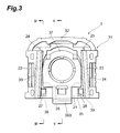
- Fig. 3 is a plan view of the base inner.
- Fig. 4 is a sectional view corresponding to a cross section along line IV-IV in Fig. 3 in a state in which the plate spring is incorporated in the base inner and in which the base inner is mounted on a base.
- Fig. 5 is a sectional view corresponding to a cross section along line V-V in Fig. 3 in a state in which the plate spring is incorporated in the base inner and in which the base inner is mounted on the base.
- Fig. 6 is a step diagram showing a step of incorporating the plate spring into the base inner.
- Fig. 7 is a sectional view schematically showing a state in which a tension is applied to the base inner by the plate spring.
- Fig. 8 is a sectional side view of a state in which a mirror assembly is mounted on a windshield of a vehicle.
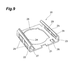
- Fig. 9 is a perspective view showing another example of the plate spring.
- Fig. 1 is an exploded perspective view of a vehicle interior accessory retainer according to the present invention
- Fig. 2 (a) a perspective view of a plate spring
- Fig. 2 (b) a perspective view of a base inner
- Fig. 3 a plan view of the base inner
- Fig. 4 a sectional view corresponding to a cross section along line IV-IV in Fig. 3 in a state in which the plate spring is incorporated in the base inner and in which the base inner is mounted on the base
- Fig. 5 a sectional view corresponding to a cross section along line V-V in Fig. 3 in a state in which the plate spring is incorporated in the base inner and in which the base inner is mounted on the base.
- the vehicle interior accessory retainer H is composed of a base 1, a plate spring 2, a base inner 3, and a mirror assembly 4.
- the base 1 is, for example, a metal member and a principal cross section thereof is approximately an isosceles trapezoid.
- the upper surface of the base 1 is, for example, a bond surface 11 to be bonded to an automotive windshield F (cf. Fig. 8).
- Contact surfaces 12, 13 extending obliquely are provided on both sides of the bond surface 11, and the lower edges of the contact surfaces 12, 13 are connected to each other through a lower surface 14.
- This lower surface 14 has an area wider than the bond surface 11, and thus the principal cross section of the base 1 is the isosceles trapezoid.
- the plate spring 2 as also shown in Fig. 2 (a), is composed of a planar portion 21, upright portions 22, 23, and base-retaining pieces 24, 25. These planar portion 21, upright portions 22, 23, and base-retaining pieces 24, 25 are formed by deforming a single metal plate.
- the planar portion 21 is of a rectangular shape on a plan view, and the upright portions 22, 23 are formed on both sides of the planar portion 21.
- a through hole 26 is formed in the center of the planar portion 21. The through hole 26 is shaped in a size enough for a projection 37 in the base inner 3, which will be described later, to pass.
- the upright portions 22, 23 are formed as standing upright each at an angle of approximately 90° from the both side faces of the planar portion 21.
- the base-retaining pieces 24, 25 are provided at side edges of the upright portions 22, 23.
- the base-retaining pieces 24, 25 are biased toward each other in a connecting direction of the upright portions 22, 23 to each other.
- the upright portions 22, 23 are provided with a taper narrowing from back to front. Furthermore, the planar portion 21 is provided with claws 27, 28 serving as a tension applying member. The claws 27, 28 are formed each by cutting a part of the planar portion 21 and they apply a biasing force directed in a cut direction.
- the plate spring 2 is coated with a lubricating coating.
- This coating is made by immersing a metal spring material processed in the shape of the plate spring 2, in a bath filled with a lubricant.
- a coating agent for the coating can be, for example, a molybdenum disulfide coat (MoS 2 coat).
- MoS 2 coat molybdenum disulfide coat
- the base inner 3 is made of resin.
- the base inner 3, as shown in Fig. 2 (b) and Fig. 3, is provided with a case 31, and this case 31 opens in the upper part and in the front part to form an upper opening 31A and a front opening 31B, respectively.
- a vertical wall 32 is formed in the rear part of the case 31 and side walls 33, 34 are formed on the sides of the case.
- a bottom plate 35 is formed in the lower part and the planar portion 21 of the plate spring 2 is mounted on this bottom plate 35.
- the side walls 33, 34 are also provided with a taper narrowing from back to front, as the upright portions 22, 23 of the plate spring 2 is.
- the upright portions 22, 23 of the plate spring 2 are located along the side walls 33, 34, respectively.
- the taper of the side walls 33, 34 has much the same angle as the taper of the upright portions 22, 23, so that the upright portions 22, 23 can be located along the side walls 33, 34.
- a socket 36 being a stay mount member is provided in a central region in the bottom plate 35.
- the socket 36 opens in the bottom and an approximately spherically bored space is formed inside the socket 36.
- the upper part of the socket 36 constitutes a projection 37 projecting above the bottom plate 35.
- grooves 38, 39 are formed on the front upper side of the bottom plate 35 and at positions on both sides of the socket 36.
- the distance between the grooves 38, 39 is approximately equal to the distance between the claws 27, 28 in the plate spring 2, and the grooves 38, 39 are formed so that the claws 27, 28 can be fitted in the grooves 38, 39, respectively.
- a notch 36A is formed in a front part of a joining part in the socket 36 with the bottom plate 35.
- the space between the lower surface of this notch 36A and the bottom plate 35 is approximately equal to the thickness of the planar portion 21 in the plate spring 2, and an edge part of the planar portion 21 in the plate spring 2 is pinched by the notch 36A and the bottom plate 35.
- the bottom plate 35 is provided with a plate spring stopper 35A and the socket 36 is provided with a base stopper 36B.
- the plate spring stopper 35A projects slightly upward from the bottom plate 35 and a projection amount thereof is approximately equal to the thickness of the planar portion 21 in the plate spring 2.
- the front face of the plate spring stopper 35A is provided with a taper rising backward, to facilitate movement of the plate spring 2 during incorporation of the plate spring 2.
- the back face of the plate spring stopper 35A stands approximately vertically to the upper surface of the bottom plate 35 to prevent a slip of the plate spring 2.
- the base stopper 36B is also provided with a taper rising backward, in the front face as the plate spring stopper 35A is, and the back face thereof stands approximately vertically to the upper surface of the bottom plate 35. In this manner, the stopper 36B facilitates assembly of the base inner 3 and prevents a slip thereof. Furthermore, the base stopper 36B has such a biasing force that it is bent when pressed downward at the tip and that it returns upward with elimination of the pressing force. In this configuration, the base stopper 36B escapes during the mounting work of the base inner 3 onto the base 1 to further facilitate the mounting of the base inner 3, and, after completion of the mounting, the base stopper 36B returns to prevent a slip off the base 1.
- the mirror assembly 4 being the accessory of the present invention is mounted and retained on the base inner 3.
- the mirror assembly 4 is provided with a stay 5 and a mirror case 6.
- the stay 5 has a stay body 51 having a bent shape on a side view, a pivot 52 is provided at one end of the stay body 51, and an accessory body pivot (hereinafter referred to as "body pivot") 53 is provided at the other end.
- the pivot 52 has much the same shape as the inner shape of the socket 36 provided in the base inner 3, and is forced into the socket 36 to be retained therein.
- a stay socket 61 is formed in the back face of the mirror case 6. This stay socket 61 has much the same contour as the body pivot 53 of the stay 5. Then the body pivot 53 of the stay 5 is forced into the stay socket 61 of the mirror case 6, to form the mirror assembly 4. A mirror is attached to a front face of the mirror case 6.
- the base 1 is first bonded and fixed to the windshield F of the vehicle as shown in Fig. 8, with an adhesive or the like.
- the plate spring 2 is incorporated into the base inner 3.
- the projection of the base inner 3 is made to pass through the through hole 26 of the plate spring 2, as shown in Fig. 6 (a).
- the back face of the planar portion 21 in the plate spring 2 is mounted on the upper surface of the bottom plate 35 in the base inner 3.
- the plate spring 2 is moved while the upright portions 22, 23 of the plate spring 2 are slid along the side walls 33, 34 of the base inner 3. Since the upright portions 22, 23 of the plate spring 2 and the side walls 33, 34 of the base inner both are provided with the taper narrowing from back to front, the plate spring 2 can be readily inserted into the base inner 3.
- the plate spring 2 As the plate spring 2 is moved to the extreme of movement of the plate spring 2, the claws 27, 28 formed in he planar portion 21 in the plate spring 2 come to be fitted into the grooves 38, 39 in the base inner 3.
- the plate spring 2 is positioned at the predetermined position relative to the base inner 3.
- the end of the planar portion 21 in the plate spring 2 is nipped by the notch 36A of the base inner 3 and the bottom plate 35.
- a tension is applied to the base inner 3 by the claws 27, 28 in contact with the bottom plate 35 of the base inner 3 and by the planar portion 21 in contact with the notch 36A of the base inner 3.
- the plate spring stopper 35A prevents the planar portion 21 in the plate spring 2 from slipping off. Therefore, the plate spring 2 is firmly attached to the base inner 3.
- the mirror assembly 4 is assembled.
- the body pivot 53 of the stay 5 is forced into the stay socket 61 of the mirror case 6 to form the mirror assembly 4.
- the pivot 52 of the stay 5 in this mirror assembly 4 is forced into the socket 36 formed in the base inner 3.
- the mirror assembly 4 is incorporated into the base inner 3 in this manner.
- the base inner 3 is mounted as slid onto the base 1, as shown in Fig. 8.
- the upright portions 22, 23 of the plate spring 2 are slid while kept in contact with the contact surfaces 12, 13 of the base 1. Since the upright portions 22, 23 are provided with the taper narrowing forward, the upright portions 22, 23 can be readily inserted into the base 1.
- the base inner 3 As the base inner 3 is slid, the end of the base 1 comes to hit the vertical wall 32 of the base inner 3 whereupon the base inner 3 is mounted on the base 1. At this time, the base 1 is retained by the base-retaining pieces 24, 25, of the plate spring 2. In this manner, the vehicle interior accessory retainer H comes to retain the mirror assembly 4.
- the upper opening 31A and the front opening 31B are formed in the base inner 3.
- the base inner 3 can be readily mounted onto the base 1.
- the provision of the front opening 31B permits the base inner 3 to be slid and mounted onto the base 1, so as to facilitate the assembling work.
- the plate spring 2 is used for retaining the base 1 in the base inner 3.
- the plate spring 2 is provided with the planar portion 21 arranged along the upper surface of the lower part in the base inner 3, and the upright portions 22, 23 arranged along the side walls 33, 34 in the base inner 3. For this reason, the plate spring 2 can be securely mounted on the base inner 3.
- the base-retaining pieces 24, 25 are formed as directed inward from the upright portions 22, 23, and the base 1 is retained in the base inner 3 by the base-retaining pieces 24, 25. For this reason, the base inner 3 becomes resistant to deterioration with age and by heat and the retaining force is maintained. Therefore, it is feasible to prevent reduction in the retaining load.
- the socket 36 Since the socket 36 has the projection 37 projecting toward the upper part, it can prevent increase in the size of the base inner 3 itself even if the socket 36 has a large size. Since the plate spring 2 is provided with the through hole 26 for letting the projection 37 pass, interference can be prevented between the plate spring 2 and the projection 37.
- the claws 27, 28 are formed in the planar portion 21 in the plate spring 2. This permits the plate spring 2 to be mounted more securely on the base inner 3. In addition, since the planar portion in the plate spring 2 is nipped between the projection 37 and the bottom plate 35, the plate spring 2 can be mounted more securely on the base inner 3. Furthermore, since the grooves 38, 39 for the claws 27, 28 to be fitted therein are formed in the bottom plate 35, the plate spring 2 can be securely positioned relative to the base inner 3.
- the plate spring can be constructed in a form shown in Fig. 9.
- the plate spring 20 shown in Fig. 9 is provided with apertures 29 as a load adjusting structure in each of the base-retaining pieces 24, 25.
- the retaining force of the base 1 can be adjusted by properly determining the positions and sizes of the apertures 29.
- the magnitude of the withstand load from the base 1 can be adjusted in this way.
- the above embodiment showed the configuration wherein the base 1 was fixed to the windshield in the vehicle interior, but the base 1 can be fixed at any other appropriate position, e.g., the ceiling.
- the above embodiment showed the mirror assembly 4 (inner mirror) as the accessory, but the accessory can also be, for example, a television camera, a cell phone holder, or the like.
Abstract
Description
- The present invention relates to a vehicle interior accessory retainer for retaining an accessory in a vehicle interior, e.g., a vehicle interior mirror or a television camera.
- A vehicle interior mirror for rearview is provided in a vehicle interior. Recently, there are cases where the vehicle interior mirror, a television camera, etc. are provided in the vehicle interior, in order to improve the functionality of vehicle. Such an accessory is attached to a part of the vehicle interior, e.g., a ceiling or an instrument panel. These accessories are structured so as to be detached from the mount part in the vehicb interior, in order to prevent breakage thereof upon exertion of large impact, e.g., collision with an occupant's head in the event of vehicle collision or the like.
- However, if during normal times the accessory is easily detached from the mount part in the vehicle interior, attachment thereof will require some labor and time. For this reason, the vehicle interior accessory retainer described in
Patent Document 1 has such a structure that during normal times the accessory is retained with some load and that the accessory is detached only when an impact force over a predetermined magnitude is exerted. Therefore, it is excellent in impact relaxation and is able to securely retain the accessory. Examples of other vehicle interior accessory retainers include an inner mirror device for vehicle disclosed inPatent Document 2, and a dropout rearview mirror mounting bracket disclosed inPatent Document 3. - [Patent Document 1] International Application Published under PCT
WO 2003/041999 - [Patent Document 2]
Japanese Patent Application Laid-Open No. 2003-118486 - [Patent Document 3] Published
Japanese Translation of PCT Application No. Hei.6-507364 - In the vehicle interior accessory retainer disclosed in the
aforementioned Patent Document 1, however, a base inner is mounted on a base by use of a linear spring. For this reason, it had the problem that if the base inner deteriorated with age or by heat, the retaining load by the linear spring decreased, so as to degrade vibration resistance. - An object of the present invention is therefore to provide a vehicle interior accessory retainer capable of securely retaining an accessory, resistant to deterioration with age and by heat, and capable of preventing reduction in the retaining load.
- A vehicle interior accessory retainer according to the present invention, which achieved the above object, comprises a base to be fixed in a vehicle interior; a base inner in which an upper opening and a front opening are formed in an upper part and in a front part, respectively, in which side walls are formed in side parts facing each other with the front opening in between in the upper opening, in which a lower part is formed at a position opposite to the upper opening with the side walls in between, and in which a stay mount part, on which a stay in an accessory body is to be mounted, is provided in the lower part; and a plate spring mounted on the base inner and arranged to retain the base in the base inner; wherein the plate spring has a planar portion arranged along an upper surface of the lower part in the base inner, upright portions standing upright from both sides of the planar portion and arranged along the side walls in the base inner, and base-retaining pieces formed as directed inward from the upright portions.
- In the vehicle interior accessory retainer according to the present invention, the upper opening and the front opening are formed in the base inner. The provision of this upper opening permits the base inner to be mounted on the base, and the provision of the front opening permits the base inner to be mounted as slid onto the base; therefore, they facilitate an assembling work.
- The plate spring is used for the base inner to retain the base. This plate spring has the planar portion arranged along the upper surface of the lower part in the base inner, and the upright portions formed as standing upright from the both sides of the planar portion and arranged along the side walls in the base inner. For this reason, it can be securely mounted along the side walls and the lower part in the base inner. In addition, the base-retaining pieces are formed as directed inward from the upright portions and the base-retaining pieces retain the base in the base inner. Since the base is retained by the plate spring in this manner, the base inner becomes unlikely to deteriorate with age and by heat, and thus the retaining force can be maintained. Therefore, it is feasible to prevent reduction in the retaining load.
- The vehicle interior accessory retainer can be constructed in a form wherein the stay mount part has a projection projecting from the lower part toward the upper part of the base inner, wherein a nip part for nipping the planar portion in the plate spring is formed between the projection and the lower part of the base inner, wherein a through hole for letting the projection in the stay mount part pass is formed in the planar portion in the plate spring, and wherein a tension applying part for applying a tension is formed between the upper surface of the lower part in the base inner and the projection in the stay mount part.
- When the stay mount part has the projection projecting from the lower part toward the upper part of the base inner as described above, it is feasible to prevent an increase in the size of the base inner itself even if the stay mount part becomes large. In this form, there is a concern about interference between the plate spring and the stay mount part, but the interference between the plate spring and the stay mount part can be prevented because the through hole for letting the projection in the stay mount part pass is formed in the plate spring. In addition, the planar portion in the plate spring is provided with the tension applying part for applying the tension between the upper surface of the lower part in the base inner and the projection in the stay mount part. For this reason, the plate spring can be mounted more securely on the base inner. In addition, since the nip part for nipping the planar portion in the plate spring is formed between the projection and the lower part of the base inner, the plate spring can be mounted still more securely on the base inner.
- The vehicle interior accessory retainer can also be constructed in a form wherein a groove for receiving the tension applying part is formed in the upper surface of the lower part in the base inner. When this groove is formed, the plate spring can be located at an appropriate position relative to the base inner.
- Furthermore, the vehicle interior accessory retainer can be constructed in a form wherein a load adjusting structure is formed in the upright portions in the plate spring. When this load adjusting structure is formed, it becomes easy to perform load design according to materials of the base inner, the plate spring, and so on.
- The vehicle interior accessory retainer can also be constructed in a form wherein at least one of the base and the plate spring is made of metal. When at least one of the base and the plate spring is made of metal, a coefficient of friction can be decreased between the base and the plate spring. Therefore, the base inner can be mounted as smoothly slid onto the base.
- The vehicle interior accessory retainer can be constructed in a form wherein the plate spring is coated with a lubricating coating. When the plate spring is coated with the lubricating coating in this manner, the base inner can be mounted as slid more smoothly onto the base.
- The vehicle interior accessory retainer according to the present invention is able to securely retain the accessory, resistant to deterioration with age and by heat, and able to prevent reduction in the retaining load.
- Fig. 1 is an exploded perspective view of a vehicle interior accessory retainer according to the present invention.
- Fig. 2 includes (a) a perspective view of a plate spring and (b) a perspective view of a base inner.
- Fig. 3 is a plan view of the base inner.
- Fig. 4 is a sectional view corresponding to a cross section along line IV-IV in Fig. 3 in a state in which the plate spring is incorporated in the base inner and in which the base inner is mounted on a base.
- Fig. 5 is a sectional view corresponding to a cross section along line V-V in Fig. 3 in a state in which the plate spring is incorporated in the base inner and in which the base inner is mounted on the base.
- Fig. 6 is a step diagram showing a step of incorporating the plate spring into the base inner.
- Fig. 7 is a sectional view schematically showing a state in which a tension is applied to the base inner by the plate spring.
- Fig. 8 is a sectional side view of a state in which a mirror assembly is mounted on a windshield of a vehicle.
- Fig. 9 is a perspective view showing another example of the plate spring.
- An embodiment of the present invention will be described below with reference to the drawings. Fig. 1 is an exploded perspective view of a vehicle interior accessory retainer according to the present invention, Fig. 2 (a) a perspective view of a plate spring, Fig. 2 (b) a perspective view of a base inner, Fig. 3 a plan view of the base inner, Fig. 4 a sectional view corresponding to a cross section along line IV-IV in Fig. 3 in a state in which the plate spring is incorporated in the base inner and in which the base inner is mounted on the base, and Fig. 5 a sectional view corresponding to a cross section along line V-V in Fig. 3 in a state in which the plate spring is incorporated in the base inner and in which the base inner is mounted on the base.
- As shown in Fig. 1, the vehicle interior accessory retainer H according to the present embodiment is composed of a
base 1, aplate spring 2, a base inner 3, and amirror assembly 4. - The
base 1 is, for example, a metal member and a principal cross section thereof is approximately an isosceles trapezoid. The upper surface of thebase 1 is, for example, abond surface 11 to be bonded to an automotive windshield F (cf. Fig. 8).Contact surfaces bond surface 11, and the lower edges of thecontact surfaces lower surface 14. Thislower surface 14 has an area wider than thebond surface 11, and thus the principal cross section of thebase 1 is the isosceles trapezoid. - The
plate spring 2, as also shown in Fig. 2 (a), is composed of aplanar portion 21,upright portions retaining pieces planar portion 21,upright portions retaining pieces planar portion 21 is of a rectangular shape on a plan view, and theupright portions planar portion 21. A throughhole 26 is formed in the center of theplanar portion 21. The throughhole 26 is shaped in a size enough for aprojection 37 in the base inner 3, which will be described later, to pass. - The
upright portions planar portion 21. The base-retainingpieces upright portions pieces upright portions base 1, thebase 1 is nipped between the base-retainingpieces base 1 is retained in the base inner 3 by biasing forces of the base-retainingpieces - The
upright portions planar portion 21 is provided withclaws claws planar portion 21 and they apply a biasing force directed in a cut direction. - The
plate spring 2 is coated with a lubricating coating. This coating is made by immersing a metal spring material processed in the shape of theplate spring 2, in a bath filled with a lubricant. A coating agent for the coating can be, for example, a molybdenum disulfide coat (MoS2 coat). When theplate spring 2 is coated with such a coating, the base inner 3 can be mounted as smoothly slid onto thebase 1. - The base inner 3 is made of resin. The base inner 3, as shown in Fig. 2 (b) and Fig. 3, is provided with a
case 31, and thiscase 31 opens in the upper part and in the front part to form anupper opening 31A and afront opening 31B, respectively. Avertical wall 32 is formed in the rear part of thecase 31 andside walls bottom plate 35 is formed in the lower part and theplanar portion 21 of theplate spring 2 is mounted on thisbottom plate 35. - The
side walls upright portions plate spring 2 is. Theupright portions plate spring 2 are located along theside walls side walls upright portions upright portions side walls - A
socket 36 being a stay mount member is provided in a central region in thebottom plate 35. Thesocket 36 opens in the bottom and an approximately spherically bored space is formed inside thesocket 36. The upper part of thesocket 36 constitutes aprojection 37 projecting above thebottom plate 35. - Furthermore,
grooves bottom plate 35 and at positions on both sides of thesocket 36. The distance between thegrooves claws plate spring 2, and thegrooves claws grooves - As shown in Fig. 4, a
notch 36A is formed in a front part of a joining part in thesocket 36 with thebottom plate 35. The space between the lower surface of thisnotch 36A and thebottom plate 35 is approximately equal to the thickness of theplanar portion 21 in theplate spring 2, and an edge part of theplanar portion 21 in theplate spring 2 is pinched by thenotch 36A and thebottom plate 35. Thesenotch 36A and theplanar portion 21 form the nip part of the present invention. - Furthermore, as shown in Fig. 5, the
bottom plate 35 is provided with aplate spring stopper 35A and thesocket 36 is provided with abase stopper 36B. Theplate spring stopper 35A projects slightly upward from thebottom plate 35 and a projection amount thereof is approximately equal to the thickness of theplanar portion 21 in theplate spring 2. The front face of theplate spring stopper 35A is provided with a taper rising backward, to facilitate movement of theplate spring 2 during incorporation of theplate spring 2. The back face of theplate spring stopper 35A stands approximately vertically to the upper surface of thebottom plate 35 to prevent a slip of theplate spring 2. - The
base stopper 36B is also provided with a taper rising backward, in the front face as theplate spring stopper 35A is, and the back face thereof stands approximately vertically to the upper surface of thebottom plate 35. In this manner, thestopper 36B facilitates assembly of the base inner 3 and prevents a slip thereof. Furthermore, thebase stopper 36B has such a biasing force that it is bent when pressed downward at the tip and that it returns upward with elimination of the pressing force. In this configuration, thebase stopper 36B escapes during the mounting work of the base inner 3 onto thebase 1 to further facilitate the mounting of the base inner 3, and, after completion of the mounting, thebase stopper 36B returns to prevent a slip off thebase 1. - The
mirror assembly 4 being the accessory of the present invention is mounted and retained on thebase inner 3. Themirror assembly 4 is provided with astay 5 and amirror case 6. Thestay 5 has astay body 51 having a bent shape on a side view, apivot 52 is provided at one end of thestay body 51, and an accessory body pivot (hereinafter referred to as "body pivot") 53 is provided at the other end. Thepivot 52 has much the same shape as the inner shape of thesocket 36 provided in the base inner 3, and is forced into thesocket 36 to be retained therein. - A
stay socket 61 is formed in the back face of themirror case 6. Thisstay socket 61 has much the same contour as thebody pivot 53 of thestay 5. Then thebody pivot 53 of thestay 5 is forced into thestay socket 61 of themirror case 6, to form themirror assembly 4. A mirror is attached to a front face of themirror case 6. - Let us describe an assembling procedure of the vehicle interior accessory retainer H having the above configuration. In the assembling procedure of the vehicle interior accessory retainer, the
base 1 is first bonded and fixed to the windshield F of the vehicle as shown in Fig. 8, with an adhesive or the like. On the other hand, theplate spring 2 is incorporated into thebase inner 3. As theplate spring 2 is incorporated into the base inner 3, the projection of the base inner 3 is made to pass through the throughhole 26 of theplate spring 2, as shown in Fig. 6 (a). In this manner, the back face of theplanar portion 21 in theplate spring 2 is mounted on the upper surface of thebottom plate 35 in thebase inner 3. Thereafter, as shown in Fig. 6 (b), theplate spring 2 is moved while theupright portions plate spring 2 are slid along theside walls upright portions plate spring 2 and theside walls plate spring 2 can be readily inserted into thebase inner 3. - As the
plate spring 2 is moved to the extreme of movement of theplate spring 2, theclaws portion 21 in theplate spring 2 come to be fitted into thegrooves base inner 3. When theclaws grooves plate spring 2 is positioned at the predetermined position relative to thebase inner 3. In addition, the end of theplanar portion 21 in theplate spring 2 is nipped by thenotch 36A of the base inner 3 and thebottom plate 35. At this time, as shown in Fig. 7, a tension is applied to the base inner 3 by theclaws bottom plate 35 of the base inner 3 and by theplanar portion 21 in contact with thenotch 36A of the base inner 3. Theplate spring stopper 35A prevents theplanar portion 21 in theplate spring 2 from slipping off. Therefore, theplate spring 2 is firmly attached to thebase inner 3. - While the
plate spring 2 is incorporated into the base inner 3, themirror assembly 4 is assembled. For implementing it, thebody pivot 53 of thestay 5 is forced into thestay socket 61 of themirror case 6 to form themirror assembly 4. Thepivot 52 of thestay 5 in thismirror assembly 4 is forced into thesocket 36 formed in thebase inner 3. Themirror assembly 4 is incorporated into the base inner 3 in this manner. - After the
mirror assembly 4 is mounted on the base inner 3 in this manner, the base inner 3 is mounted as slid onto thebase 1, as shown in Fig. 8. In the work of mounting the base inner 3 onto thebase 1, theupright portions plate spring 2 are slid while kept in contact with the contact surfaces 12, 13 of thebase 1. Since theupright portions upright portions base 1. - As the base inner 3 is slid, the end of the
base 1 comes to hit thevertical wall 32 of the base inner 3 whereupon the base inner 3 is mounted on thebase 1. At this time, thebase 1 is retained by the base-retainingpieces plate spring 2. In this manner, the vehicle interior accessory retainer H comes to retain themirror assembly 4. - In the vehicle interior accessory retainer H retaining the
mirror assembly 4, as described above, theupper opening 31A and thefront opening 31B are formed in thebase inner 3. For this reason, the base inner 3 can be readily mounted onto thebase 1. The provision of thefront opening 31B permits the base inner 3 to be slid and mounted onto thebase 1, so as to facilitate the assembling work. - The
plate spring 2 is used for retaining thebase 1 in thebase inner 3. Theplate spring 2 is provided with theplanar portion 21 arranged along the upper surface of the lower part in the base inner 3, and theupright portions side walls base inner 3. For this reason, theplate spring 2 can be securely mounted on thebase inner 3. In addition, the base-retainingpieces upright portions base 1 is retained in the base inner 3 by the base-retainingpieces - Since the
socket 36 has theprojection 37 projecting toward the upper part, it can prevent increase in the size of the base inner 3 itself even if thesocket 36 has a large size. Since theplate spring 2 is provided with the throughhole 26 for letting theprojection 37 pass, interference can be prevented between theplate spring 2 and theprojection 37. Theclaws planar portion 21 in theplate spring 2. This permits theplate spring 2 to be mounted more securely on thebase inner 3. In addition, since the planar portion in theplate spring 2 is nipped between theprojection 37 and thebottom plate 35, theplate spring 2 can be mounted more securely on thebase inner 3. Furthermore, since thegrooves claws bottom plate 35, theplate spring 2 can be securely positioned relative to thebase inner 3. - The above described the preferred embodiment of the present invention, but it is noted that the present invention is by no means intended to be limited to the above embodiment. For example, the plate spring can be constructed in a form shown in Fig. 9. The
plate spring 20 shown in Fig. 9 is provided withapertures 29 as a load adjusting structure in each of the base-retainingpieces base 1 can be adjusted by properly determining the positions and sizes of theapertures 29. The magnitude of the withstand load from thebase 1 can be adjusted in this way. The above embodiment showed the configuration wherein thebase 1 was fixed to the windshield in the vehicle interior, but thebase 1 can be fixed at any other appropriate position, e.g., the ceiling. Furthermore, the above embodiment showed the mirror assembly 4 (inner mirror) as the accessory, but the accessory can also be, for example, a television camera, a cell phone holder, or the like.
Claims (6)
- A vehicle interior accessory retainer comprising:a base to be fixed in a vehicle interior;a base inner in which an upper opening and a front opening are formed in an upper part and in a front part, respectively, in which side walls are formed in side parts facing each other with the front opening in between in the upper opening, in which a lower part is formed at a position opposite to the upper opening with the side walls in between, and in which a stay mount part, on which a stay in an accessory body is to be mounted, is provided in the lower part; anda plate spring mounted on the base inner and arranged to retain the base in the base inner;wherein the plate spring has a planar portion arranged along an upper surface of the lower part in the base inner, upright portions standing upright from both sides of the planar portion and arranged along the side walls in the base inner, and base-retaining pieces formed as directed inward from the upright portions.
- The vehicle interior accessory retainer according to claim 1,
wherein the stay mount part has a projection projecting from the lower part toward the upper part of the base inner, and a nip part for nipping the planar portion in the plate spring is formed between the projection and the lower part of the base inner, and
wherein a through hole for letting the projection in the stay mount part pass is formed in the planar portion in the plate spring, and a tension applying part for applying a tension is formed between the upper surface of the lower part in the base inner and the projection in the stay mount part. - The vehicle interior accessory retainer according to claim 2,
wherein a groove for receiving the tension applying part is formed in the upper surface of the lower part in the base inner. - The vehicle interior accessory retainer according to any one of claims 1 to 3,
wherein a load adjusting structure is formed in the upright portions in the plate spring. - The vehicle interior accessory retainer according to any one of claims 1 to 4,
wherein at least one of the base and the plate spring is made of metal. - The vehicle interior accessory retainer according to any one of claims 1 to 5,
wherein the plate spring is coated with a lubricating coating.
Applications Claiming Priority (1)
| Application Number | Priority Date | Filing Date | Title |
|---|---|---|---|
| JP2006097546A JP4713386B2 (en) | 2006-03-31 | 2006-03-31 | Car interior accessory holding device |
Publications (2)
| Publication Number | Publication Date |
|---|---|
| EP1839949A1 true EP1839949A1 (en) | 2007-10-03 |
| EP1839949B1 EP1839949B1 (en) | 2009-09-23 |
Family
ID=38222162
Family Applications (1)
| Application Number | Title | Priority Date | Filing Date |
|---|---|---|---|
| EP07100815A Expired - Fee Related EP1839949B1 (en) | 2006-03-31 | 2007-01-19 | Vehicle interior accessory retainer |
Country Status (5)
| Country | Link |
|---|---|
| US (1) | US7717394B2 (en) |
| EP (1) | EP1839949B1 (en) |
| JP (1) | JP4713386B2 (en) |
| CN (1) | CN101045438B (en) |
| DE (1) | DE602007002514D1 (en) |
Families Citing this family (18)
| Publication number | Priority date | Publication date | Assignee | Title |
|---|---|---|---|---|
| DE102007028162A1 (en) * | 2007-06-20 | 2008-12-24 | Dr. Ing. H.C. F. Porsche Aktiengesellschaft | Fastening device for an interior rearview mirror of motor vehicles on an inner side of a windshield |
| US20100272300A1 (en) * | 2007-07-10 | 2010-10-28 | Continental Teves Ag & Co. Ohg | Device for holding vehicle sensors |
| JP5017048B2 (en) * | 2007-10-12 | 2012-09-05 | 株式会社村上開明堂 | Inner mirror mounting structure |
| DE102008050320A1 (en) * | 2008-10-04 | 2010-04-08 | Daimler Ag | Support device for attachment to a window of a motor vehicle |
| US20100219305A1 (en) * | 2009-02-27 | 2010-09-02 | Nissan Technical Center North America, Inc. | Clip design for attaching a bracket to an existing bracket or panel |
| US9156403B2 (en) | 2010-06-04 | 2015-10-13 | Magna Mirrors Of America, Inc. | Mirror mounting assembly with adapter |
| US8430368B2 (en) * | 2010-11-15 | 2013-04-30 | Globe Union Industrial Corp. | Wall mounting bath accessory assembly |
| US8925891B2 (en) * | 2011-09-14 | 2015-01-06 | Gentex Corporation | Reverse detach mounting system |
| DE102012024275A1 (en) * | 2012-12-12 | 2014-06-26 | GM Global Technology Operations LLC (n. d. Gesetzen des Staates Delaware) | Fastening device for fastening mechanical, electrical and / or electronic modules |
| US10434946B2 (en) * | 2014-02-12 | 2019-10-08 | Gentex Corporation | Spring secured mounting system |
| CN105383386A (en) * | 2015-11-26 | 2016-03-09 | 重庆奥科伦实业发展有限公司 | Mounting method of inner rear-view mirror of automobile |
| DE112018001306T5 (en) * | 2017-03-13 | 2019-11-28 | Murakami Corporation | Fastening structure equipped with a discharge mechanism for an in-vehicle device |
| US10190610B1 (en) | 2017-10-13 | 2019-01-29 | Gentex Corporation | Mounting assembly for rearview device |
| DE212018000374U1 (en) | 2017-12-08 | 2020-07-08 | Gentex Corporation | Preloaded two-leaf torsion spring assembly for rear view devices |
| US10974650B2 (en) | 2017-12-11 | 2021-04-13 | Gentex Corporation | Rearview device mount and attachment method |
| US11254264B2 (en) * | 2018-01-31 | 2022-02-22 | Murakami Corporation | Sensor assembling structure for rotary mounting-type windshield mounted inner mirror for vehicle |
| EP3860880B1 (en) * | 2018-10-02 | 2022-12-21 | Gentex Corporation | Adjustable mounting mechanism for a rearview assembly |
| US11623567B2 (en) * | 2020-03-10 | 2023-04-11 | Gentex Corporation | Ramps for rearview assembly mounts |
Citations (4)
| Publication number | Priority date | Publication date | Assignee | Title |
|---|---|---|---|---|
| WO1993016900A1 (en) * | 1992-02-25 | 1993-09-02 | Gentex Corporation | Breakaway rearview mirror mounting bracket |
| US5377948A (en) | 1991-05-21 | 1995-01-03 | Gentex Corporation | Breakaway rearview mirror mounting bracket |
| US5820097A (en) * | 1997-01-10 | 1998-10-13 | Donnelly Corporation | Breakaway accessory mounting assembly for vehicles and windshield mounted button therefor |
| US5931440A (en) * | 1996-11-01 | 1999-08-03 | Gentex Corporation | Regulated attachment for mirror mount |
Family Cites Families (8)
| Publication number | Priority date | Publication date | Assignee | Title |
|---|---|---|---|---|
| JPS6142349U (en) * | 1984-08-24 | 1986-03-18 | トヨタ自動車株式会社 | Indoor mirror mounting structure |
| JPS61115748A (en) * | 1984-11-12 | 1986-06-03 | Ichikoh Ind Ltd | Motor-driven foldable door mirror |
| US4632348A (en) * | 1985-12-12 | 1986-12-30 | General Motors Corporation | Mounting arrangement for a mirror |
| US5330149A (en) | 1993-01-28 | 1994-07-19 | Donnelly Corporation | Breakaway accessory mounting for vehicles |
| US5377949A (en) | 1993-02-25 | 1995-01-03 | Donnelly Corporation | Breakaway accessory mounting for vehicles |
| JP3951659B2 (en) | 2001-10-11 | 2007-08-01 | 市光工業株式会社 | Inner mirror device for vehicles |
| WO2003041999A1 (en) * | 2001-11-16 | 2003-05-22 | Murakami Corporation | Accessory holder in cabin |
| JP2005119562A (en) | 2003-10-17 | 2005-05-12 | Murakami Corp | Electric connection structure for attached unit for vehicle and electric connection structure for rearview mirror |
-
2006
- 2006-03-31 JP JP2006097546A patent/JP4713386B2/en active Active
-
2007
- 2007-01-10 CN CN2007100038704A patent/CN101045438B/en active Active
- 2007-01-19 EP EP07100815A patent/EP1839949B1/en not_active Expired - Fee Related
- 2007-01-19 DE DE602007002514T patent/DE602007002514D1/en active Active
- 2007-01-23 US US11/626,000 patent/US7717394B2/en not_active Expired - Fee Related
Patent Citations (4)
| Publication number | Priority date | Publication date | Assignee | Title |
|---|---|---|---|---|
| US5377948A (en) | 1991-05-21 | 1995-01-03 | Gentex Corporation | Breakaway rearview mirror mounting bracket |
| WO1993016900A1 (en) * | 1992-02-25 | 1993-09-02 | Gentex Corporation | Breakaway rearview mirror mounting bracket |
| US5931440A (en) * | 1996-11-01 | 1999-08-03 | Gentex Corporation | Regulated attachment for mirror mount |
| US5820097A (en) * | 1997-01-10 | 1998-10-13 | Donnelly Corporation | Breakaway accessory mounting assembly for vehicles and windshield mounted button therefor |
Also Published As
| Publication number | Publication date |
|---|---|
| US7717394B2 (en) | 2010-05-18 |
| US20070228247A1 (en) | 2007-10-04 |
| JP4713386B2 (en) | 2011-06-29 |
| CN101045438B (en) | 2012-06-06 |
| DE602007002514D1 (en) | 2009-11-05 |
| CN101045438A (en) | 2007-10-03 |
| EP1839949B1 (en) | 2009-09-23 |
| JP2007269182A (en) | 2007-10-18 |
Similar Documents
| Publication | Publication Date | Title |
|---|---|---|
| EP1839949B1 (en) | Vehicle interior accessory retainer | |
| JP3872790B2 (en) | Car interior accessory holding device | |
| US6076233A (en) | Grab rail and hook assembly for a vehicle | |
| US7784953B2 (en) | Quick-attach mirror mounting structure facilitating assembly | |
| US11285876B2 (en) | Drop-off mechanism-equipped attachment structure for in-vehicle device | |
| KR100743503B1 (en) | Inside rearview mirror apparatus for vehicle | |
| US10967808B2 (en) | Interior cover mount assembly | |
| EP3267056A1 (en) | Rotation mechanism | |
| JP4233506B2 (en) | Automotive instrument panel mounting device | |
| JP2001065524A (en) | Clip | |
| US5966255A (en) | Escape device for an inner mirror | |
| JP6440523B2 (en) | Vehicle rearview mirror | |
| FR2975352A1 (en) | Device for relatively positioning rear-view mirror module with respect to support of vehicle body, has leg integrated with portion of base plate, where joint is interposed between base plate and support whose slide notch cooperates with leg | |
| US20220334348A1 (en) | Interior rearview mirror assembly with overmolded metal mount and anti-camout tab | |
| JP4807698B2 (en) | Vehicle rearview mirror coupling device | |
| US11254292B2 (en) | Coupling clip, wiper lever, and wiper blade | |
| CN114867638B (en) | Auxiliary handle | |
| JP2006248474A (en) | Bonding device for rear view mirror of vehicle | |
| EP0659608A1 (en) | Mirror support bracket | |
| CN116803719A (en) | Sun shield mounting device | |
| JP6721497B2 (en) | Door frame garnish | |
| JP2001105950A (en) | Clip | |
| JP2023181532A (en) | Attachment device of vehicle interior member, base member for the same, and attachment member for the same | |
| KR20210074718A (en) | Vehicle terminal holder that can adjust the length and shape | |
| JP2004136733A (en) | Mounting structure for assist grip |
Legal Events
| Date | Code | Title | Description |
|---|---|---|---|
| PUAI | Public reference made under article 153(3) epc to a published international application that has entered the european phase |
Free format text: ORIGINAL CODE: 0009012 |
|
| AK | Designated contracting states |
Kind code of ref document: A1 Designated state(s): AT BE BG CH CY CZ DE DK EE ES FI FR GB GR HU IE IS IT LI LT LU LV MC NL PL PT RO SE SI SK TR |
|
| AX | Request for extension of the european patent |
Extension state: AL BA HR MK YU |
|
| 17P | Request for examination filed |
Effective date: 20071025 |
|
| 17Q | First examination report despatched |
Effective date: 20071218 |
|
| AKX | Designation fees paid |
Designated state(s): DE |
|
| GRAP | Despatch of communication of intention to grant a patent |
Free format text: ORIGINAL CODE: EPIDOSNIGR1 |
|
| GRAS | Grant fee paid |
Free format text: ORIGINAL CODE: EPIDOSNIGR3 |
|
| GRAA | (expected) grant |
Free format text: ORIGINAL CODE: 0009210 |
|
| AK | Designated contracting states |
Kind code of ref document: B1 Designated state(s): DE |
|
| REF | Corresponds to: |
Ref document number: 602007002514 Country of ref document: DE Date of ref document: 20091105 Kind code of ref document: P |
|
| PLBE | No opposition filed within time limit |
Free format text: ORIGINAL CODE: 0009261 |
|
| STAA | Information on the status of an ep patent application or granted ep patent |
Free format text: STATUS: NO OPPOSITION FILED WITHIN TIME LIMIT |
|
| 26N | No opposition filed |
Effective date: 20100624 |
|
| PGFP | Annual fee paid to national office [announced via postgrant information from national office to epo] |
Ref country code: DE Payment date: 20150113 Year of fee payment: 9 |
|
| REG | Reference to a national code |
Ref country code: DE Ref legal event code: R119 Ref document number: 602007002514 Country of ref document: DE |
|
| PG25 | Lapsed in a contracting state [announced via postgrant information from national office to epo] |
Ref country code: DE Free format text: LAPSE BECAUSE OF NON-PAYMENT OF DUE FEES Effective date: 20160802 |