EP1842499A1 - Treatment instrument for endoscope - Google Patents
Treatment instrument for endoscope Download PDFInfo
- Publication number
- EP1842499A1 EP1842499A1 EP06711971A EP06711971A EP1842499A1 EP 1842499 A1 EP1842499 A1 EP 1842499A1 EP 06711971 A EP06711971 A EP 06711971A EP 06711971 A EP06711971 A EP 06711971A EP 1842499 A1 EP1842499 A1 EP 1842499A1
- Authority
- EP
- European Patent Office
- Prior art keywords
- endoscope
- section
- guide catheter
- cap
- treatment instrument
- Prior art date
- Legal status (The legal status is an assumption and is not a legal conclusion. Google has not performed a legal analysis and makes no representation as to the accuracy of the status listed.)
- Withdrawn
Links
Images


Classifications
-
- A—HUMAN NECESSITIES
- A61—MEDICAL OR VETERINARY SCIENCE; HYGIENE
- A61B—DIAGNOSIS; SURGERY; IDENTIFICATION
- A61B17/00—Surgical instruments, devices or methods, e.g. tourniquets
- A61B17/34—Trocars; Puncturing needles
- A61B17/3468—Trocars; Puncturing needles for implanting or removing devices, e.g. prostheses, implants, seeds, wires
-
- A—HUMAN NECESSITIES
- A61—MEDICAL OR VETERINARY SCIENCE; HYGIENE
- A61M—DEVICES FOR INTRODUCING MEDIA INTO, OR ONTO, THE BODY; DEVICES FOR TRANSDUCING BODY MEDIA OR FOR TAKING MEDIA FROM THE BODY; DEVICES FOR PRODUCING OR ENDING SLEEP OR STUPOR
- A61M1/00—Suction or pumping devices for medical purposes; Devices for carrying-off, for treatment of, or for carrying-over, body-liquids; Drainage systems
- A61M1/84—Drainage tubes; Aspiration tips
-
- A—HUMAN NECESSITIES
- A61—MEDICAL OR VETERINARY SCIENCE; HYGIENE
- A61B—DIAGNOSIS; SURGERY; IDENTIFICATION
- A61B1/00—Instruments for performing medical examinations of the interior of cavities or tubes of the body by visual or photographical inspection, e.g. endoscopes; Illuminating arrangements therefor
- A61B1/00112—Connection or coupling means
- A61B1/00121—Connectors, fasteners and adapters, e.g. on the endoscope handle
- A61B1/00128—Connectors, fasteners and adapters, e.g. on the endoscope handle mechanical, e.g. for tubes or pipes
-
- A—HUMAN NECESSITIES
- A61—MEDICAL OR VETERINARY SCIENCE; HYGIENE
- A61B—DIAGNOSIS; SURGERY; IDENTIFICATION
- A61B1/00—Instruments for performing medical examinations of the interior of cavities or tubes of the body by visual or photographical inspection, e.g. endoscopes; Illuminating arrangements therefor
- A61B1/00131—Accessories for endoscopes
- A61B1/0014—Fastening element for attaching accessories to the outside of an endoscope, e.g. clips, clamps or bands
-
- A—HUMAN NECESSITIES
- A61—MEDICAL OR VETERINARY SCIENCE; HYGIENE
- A61B—DIAGNOSIS; SURGERY; IDENTIFICATION
- A61B1/00—Instruments for performing medical examinations of the interior of cavities or tubes of the body by visual or photographical inspection, e.g. endoscopes; Illuminating arrangements therefor
- A61B1/012—Instruments for performing medical examinations of the interior of cavities or tubes of the body by visual or photographical inspection, e.g. endoscopes; Illuminating arrangements therefor characterised by internal passages or accessories therefor
- A61B1/018—Instruments for performing medical examinations of the interior of cavities or tubes of the body by visual or photographical inspection, e.g. endoscopes; Illuminating arrangements therefor characterised by internal passages or accessories therefor for receiving instruments
-
- A—HUMAN NECESSITIES
- A61—MEDICAL OR VETERINARY SCIENCE; HYGIENE
- A61B—DIAGNOSIS; SURGERY; IDENTIFICATION
- A61B17/00—Surgical instruments, devices or methods, e.g. tourniquets
- A61B17/00234—Surgical instruments, devices or methods, e.g. tourniquets for minimally invasive surgery
- A61B2017/00292—Surgical instruments, devices or methods, e.g. tourniquets for minimally invasive surgery mounted on or guided by flexible, e.g. catheter-like, means
- A61B2017/0034—Surgical instruments, devices or methods, e.g. tourniquets for minimally invasive surgery mounted on or guided by flexible, e.g. catheter-like, means adapted to be inserted through a working channel of an endoscope
-
- A—HUMAN NECESSITIES
- A61—MEDICAL OR VETERINARY SCIENCE; HYGIENE
- A61B—DIAGNOSIS; SURGERY; IDENTIFICATION
- A61B17/00—Surgical instruments, devices or methods, e.g. tourniquets
- A61B2017/00477—Coupling
-
- A—HUMAN NECESSITIES
- A61—MEDICAL OR VETERINARY SCIENCE; HYGIENE
- A61B—DIAGNOSIS; SURGERY; IDENTIFICATION
- A61B90/00—Instruments, implements or accessories specially adapted for surgery or diagnosis and not covered by any of the groups A61B1/00 - A61B50/00, e.g. for luxation treatment or for protecting wound edges
- A61B90/03—Automatic limiting or abutting means, e.g. for safety
- A61B2090/033—Abutting means, stops, e.g. abutting on tissue or skin
- A61B2090/036—Abutting means, stops, e.g. abutting on tissue or skin abutting on tissue or skin
-
- A—HUMAN NECESSITIES
- A61—MEDICAL OR VETERINARY SCIENCE; HYGIENE
- A61F—FILTERS IMPLANTABLE INTO BLOOD VESSELS; PROSTHESES; DEVICES PROVIDING PATENCY TO, OR PREVENTING COLLAPSING OF, TUBULAR STRUCTURES OF THE BODY, e.g. STENTS; ORTHOPAEDIC, NURSING OR CONTRACEPTIVE DEVICES; FOMENTATION; TREATMENT OR PROTECTION OF EYES OR EARS; BANDAGES, DRESSINGS OR ABSORBENT PADS; FIRST-AID KITS
- A61F2/00—Filters implantable into blood vessels; Prostheses, i.e. artificial substitutes or replacements for parts of the body; Appliances for connecting them with the body; Devices providing patency to, or preventing collapsing of, tubular structures of the body, e.g. stents
- A61F2/95—Instruments specially adapted for placement or removal of stents or stent-grafts
-
- A—HUMAN NECESSITIES
- A61—MEDICAL OR VETERINARY SCIENCE; HYGIENE
- A61F—FILTERS IMPLANTABLE INTO BLOOD VESSELS; PROSTHESES; DEVICES PROVIDING PATENCY TO, OR PREVENTING COLLAPSING OF, TUBULAR STRUCTURES OF THE BODY, e.g. STENTS; ORTHOPAEDIC, NURSING OR CONTRACEPTIVE DEVICES; FOMENTATION; TREATMENT OR PROTECTION OF EYES OR EARS; BANDAGES, DRESSINGS OR ABSORBENT PADS; FIRST-AID KITS
- A61F2/00—Filters implantable into blood vessels; Prostheses, i.e. artificial substitutes or replacements for parts of the body; Appliances for connecting them with the body; Devices providing patency to, or preventing collapsing of, tubular structures of the body, e.g. stents
- A61F2/02—Prostheses implantable into the body
- A61F2/04—Hollow or tubular parts of organs, e.g. bladders, tracheae, bronchi or bile ducts
- A61F2002/041—Bile ducts
Definitions
- the present invention relates to an endoscopic treatment instrument used for endoscopic surgery and endoscopy for pancreaticobiliary ducts.
- the present application is based on patent application No. 2005-0019346 filed January 27, 2005, in Japan , the content of which is incorporated herein by reference.
- a drainage tube (drainage tube) is retained in a human body through an endoscope inserted into the human body during a manipulation conducted for secretory fluid drainage from a bile duct and a pancreatic duct.
- the drainage tube retainer proposed as an endoscopic treatment instrument includes a guide tube that can be extended and retracted along an elastic guidewire previously inserted in the human body; and an elastic pusher tube for pushing the drainage tube fit to the guide tube toward a distal end of the guide tube (see Patent documents 1 and 2 as follows).
- the distal end of the guidewire is inserted through a treatment instrument insertion channel formed in the endoscope.
- the distal end of the guide tube is inserted next into the bile duct along the guidewire inserted through the treatment instrument insertion channel.
- the guide tube of the foregoing conventional endoscopic treatment instrument must be maintained at a certain fixed position relative to the endoscope.
- an attempt to slide the pusher tube along the guide tube moves the guide tube together with the pusher tube because of a frictional force between the guide tube and the pusher tube; therefore, the position of the guide tube inevitably changes relative to the endoscope.
- the movement of the pusher tube toward a distal end of the guide tube must be carried out simultaneously by the same amount as the movement of the guide tube toward a manipulation side. Since these movements cannot be carried out by the endoscopist alone, the endoscopist and a supporter will meet difficulty due to such a complex cooperation.
- the present invention was conceived in consideration of the foregoing circumstances, and an object thereof is to provide an endoscopic treatment instrument with which an endoscopist alone can slide a hollow section along an elongated section that is inserted in the hollow section such that the elongated section is retained at a certain fixed position.
- An endoscopic treatment instrument according to the present invention inserted through a channel of an endoscope from a endoscope port includes: an elongated section for slidably supporting a retainer retained in a live organ through the channel; a hollow section disposed in the exterior of the elongated section and slidably supported by the elongated section; and a connecting section provided to the hollow section for positioning the hollow section relative to the endoscope so that a direction in which the hollow section is inserted through the channel substantially coincides with a direction in which the hollow section is retracted from the hollow section.
- the endoscopic treatment instrument positions the hollow section relative to the endoscope via the connecting section, the direction in which the hollow section is inserted through the channel of the endoscope substantially coincides with the direction in which the elongated section is retracted from the channel; therefore the operations to insert the hollow section through the channel and to retract the elongated section from the hollow section can be carried out simultaneously by one-handed manipulation. Carrying out these two operations simultaneously permits the hollow section to be inserted through the channel. On the other hand, the elongated section is retracted from the hollow section by the length equal to an insertion length of the hollow section. To be more specific, apparently the elongated section remains at a predetermined position in the channel and only the hollow section is inserted through the channel along the elongated section. Since the present invention allows an endoscopist alone to carry out the above operations, complex manipulation can be avoided.
- the elongated section be capable of sliding along a guidewire inserted through the channel.
- the endoscopic treatment instrument allows the direction in which the elongated section previously inserted through the endoscope port is inserted through the channel along the guidewire to coincide with the direction in which the guidewire is retracted from the elongated section after the elongated section is fitted to the guidewire so that the guidewire previously inserted through the channel is inserted in the interior of the elongated section; therefore, the operations to insert the elongated section through the channel and to retract the guidewire from the elongated section can be carried simultaneously one-handed. Carrying out these two operations simultaneously permits the elongated section to be inserted through the channel.
- the guidewire is retracted from the hollow section by the length equal to an insertion length of the elongated section.
- the guidewire remains at a predetermined position in the channel and only the elongated section is inserted through the channel along the guidewire. Since the present invention allows an endoscopist alone to carry out the above operations, complex manipulation can be avoided.
- the connecting section be provided with an elastically deformable, approximately C-shaped engagement member.
- the connecting section can be rotated relative to the endoscope in a direction along an arch of the substantially C-shaped engagement member.
- the connecting section attached to the endoscope via an endoscope adapter attached to an operation section of the endoscope for rotatively supporting the connecting section be detachable.
- the endoscopic treatment instrument allows the proximal end of the hollow section to be fixed in a direction toward the endoscope port separately by a predetermined distance from the operation section of the endoscope by attaching the endoscope adapter to the operation section of the endoscope and attaching the connecting section to the adapter.
- the endoscopic treatment instrument according to the present invention further include a cap disposed at a proximal end of the elongated section so that the cap is detachable from the connecting section.
- the endoscopic treatment instrument allows the elongated section and the hollow section to be simultaneously inserted through the channel of the endoscope along the guidewire if the cap is previously attached to the connecting section. Also, detaching the cap from the connecting section permits the hollow section to be moved longitudinally along the elongated section.
- the endoscopic treatment instrument according to the present invention further include a cap disposed at a proximal end of the elongated section so that the cap is detachable from the elongated section.
- the endoscopic treatment instrument allows the hollow section to be fitted to the elongated section not only from the distal end but also from the proximal end if the cap is detached from the elongated section.
- the cap be provided with an elastically deformable, approximately C-shaped engagement member.
- the round surface of the operation section, etc., of the endoscope permits the cap to be positioned and engaged at a certain position of the endoscope by elastically deforming the approximately C-shaped engagement member of the endoscopic treatment instrument according to the present invention.
- the cap can be rotated relative to the endoscope in a direction along an arch of the substantially C-shaped engagement member.
- the cap attached to the endoscope via an endoscope adapter attached to an operation section of the endoscope so as to rotatively support the cap be detachable.
- the endoscopic treatment instrument allows the proximal end of the elongated section to be fixed in a direction toward the endoscope port separately by a predetermined distance from the operation section of the endoscope by attaching the endoscope adapter to the operation section of the endoscope and attaching the cap to the adapter.
- the endoscopic treatment instrument allows an endoscopist alone to slide a hollow section along an elongated section so that the elongated section that is inserted in the hollow section is retained at a certain position.
- a drainage tube retainer (endoscopic treatment instrument) 1 is an instrument retained in a constriction 8 in a bile duct 7, etc.
- the drainage tube retainer 1 can extend and retract in a channel not shown in the drawings along a guidewire 5 inserted in the channel from an endoscope port 3 of an endoscope 2.
- a guide cathether (elongated section) 10 is provided to the drainage tube retainer 1; a pusher tube (elongated section) 11; a pusher cap (connecting section) 13; and a cap 15.
- the guide catheter 10 fitted to the drainage tube 6 so as to be inserted in the drainage tube 6 slidably supports the drainage tube 6.
- the guidewire 5 is inserted through the guide catheter 10.
- the pusher tube 11 fitted to the guide catheter 10 so as to pass the guide catheter 10 therethrough is slidably supported by the guide catheter 10.
- the pusher cap 13 provided to a proximal end of the pusher tube 11 positions the proximal end of the pusher tube 11 relative to an operation section 12 of the endoscope 2 so that a direction in which the pusher tube 11 is inserted into the channel substantially coincides with a direction in which the guide catheter 10 is retracted from the pusher tube 11.
- the cap 15 is provided to a proximal end of the guide catheter 10.
- the guide catheter 10 is considerably longer than the total length of the pusher tube 11 and the drainage tube 6 so that the distal end of the guide catheter 10 protrudes ahead of the drainage tube 6 when the guide catheter 10 is fitted to the pusher tube 11 and further fitted to the drainage tube 6 disposed ahead of the distal end of the pusher tube 11.
- an approximately C-shaped and elastically deformable hook (engagement member) 16 is provided to the pusher cap 13 to have its distal end directed toward the distal end of the pusher tube 11.
- a male thread section 17 Provided to the proximal end of the pusher cap 13 is a male thread section 17.
- a female thread section 18 Detachably provided to the distal end of the cap 15 is a female thread section 18 that engages with the male thread section 17.
- flaps 20A and 20B disposed to both ends of the drainage tube 6 are flaps 20A and 20B.
- the flaps 20A and 20B expand when retained in the interior of the bile duct 7 and engage to living body organs so as to prevent the drainage tube 6 from misaligning.
- a mark 21 indicating a manufacturing lot number or a model number, etc., of the drainage tube 6 is printed in the vicinity of one of the flaps 20A and 20B, e.g., the flap 20B, that is disposed nearer to the endoscope 2 when the drainage tube 6 is retained in the body ("4XK" is printed in the example illustrated in FIG. 3.).
- an endoscopic adapter 22 Detachably attached to the operation section 12 of the endoscope 2 is an endoscopic adapter 22 that rotatively supports the hook 16 of the pusher cap 13.
- the endoscopic adapter 22 is provided with an adapter body 23, a cylindrical treatment instrument fixture 25, and an endoscope fixture 26.
- a hook 16 slidably engages to the treatment instrument fixture 25 provided to an end of the adapter body 23.
- the approximately cylindrical endoscope fixture 26 is provided to the other end of the adapter body 23 in which a part of the cylindrical fixture is notched.
- FIG. 4 An insertion section of the endoscope 2 is first inserted into a body cavity so as to reach the distal end into the vicinity of a duodenal papilla. Consequently the guidewire 5 is inserted into a channel not shown in the drawing from the endoscope port 3 of the endoscope 2 so as to be inserted through the constriction 8 of the bile duct 7.
- the endoscope fixture 26 of the endoscopic adapter 22 is attached at a predetermined position of the operation section 12 of the endoscope 2.
- the distal end of the guide catheter 10 fitted to the drainage tube 6 and the pusher tube 11 is fitted to the guidewire 5 so that the proximal end of the guidewire 5 protruding from the endoscope port 3 is inserted in the guide catheter 10.
- a part of the drainage tube 6 and a part of the pusher tube 11 are inserted through the channel.
- the guidewire 5, the guide catheter 10 fitted to the guidewire 5 , and the pusher tube 11 fitted to the guide catheter 10 are folded together at some midpoints thereof them in the vicinity of the endoscope port 3.
- the hook 16 is then hung on the treatment instrument fixture 25 of the endoscopic adapter 22. Accordingly the hook 16 is adjustably rotated on the treatment instrument fixture 25 so that the cap 15 faces the endoscope port 3 and so that the pusher tube 11 and the guidewire 5 having protruded from the cap 15 are disposed substantially in parallel.
- the endoscopist can conduct an operation of inserting the pusher tube 11 and the guide catheter 10 into the channel from the endoscope port 3 and an operation of retracting the guidewire 5 from the guide catheter 10 simultaneously by a single-handed manipulation.
- the cap 15 is rotated relative to the pusher cap 13 so as to remove the cap 15 from the pusher cap 13.
- the cap 15 is grasped and the guide catheter 10 and the guidewire 5 fitted to the guide catheter 10 are retracted from the pusher cap 13 so that the guide catheter 10 and the pusher tube 11 that have protruded from the pusher cap 13 are substantially parallel in the vicinity of the endoscope port 3.
- the endoscopist can conduct an operation of inserting the pusher tube 11 into the channel from the endoscope port 3 and an operation of retracting the guide catheter 10 and the guidewire 5 from the pusher tube 11 simultaneously by a single-handed manipulation.
- repeating the above operations permits the pusher tube 11 to be inserted through the channel while the distal end of the guide catheter 10 and the distal end of the guidewire 5 remain at the predetermined positions, and permits the distal end of the pusher tube 11 to move to a desirable position.
- the drainage tube 11 is pushed toward the distal end of the pusher tube 11 to be inserted through the bile duct 7.
- the endoscopic adapter 22 attached to the operation section 12 of the endoscope 2 permits the proximal end of the pusher tube 11 of the above drainage tube retainer 1 to be fixed separately from the operation section 12 of the endoscope 2 by a predetermined distance and to be directed toward the endoscope port 3.
- the pusher cap 13 having the elastically deformable hook 16 can be positioned and engaged at a round surface part of the treatment instrument fixture 25. Furthermore, the pusher cap 13 can be rotated relative to the endoscope 2 in a direction along an arch of the substantially C-shaped hook 16.
- the guidewire 5, the guide catheter 10, and the pusher tube 11 can be folded in the vicinity of the endoscope port 3; therefore, the guidewire 5 can be disposed substantially in parallel with the guide catheter 10 and the pusher tube 11. This allows the direction in which the pusher tube 11 and the guide catheter 10 are inserted through the channel from the endoscope port 3 to substantially coincide with the direction in which the guidewire 5 is retracted from the guide catheter 10.
- the endoscopist alone having connected the cap 15 to the pusher cap 13 can conduct the operation of inserting two tubes, i.e., the guide catheter 10 and the pusher tube 11 fitted to the guide catheter 10 into the channel along the guidewire 5 while the distal end of the guidewire 5 is retained at a certain position.
- the endoscopist alone having detached the cap 15 from the pusher cap 13 can conduct the operation of inserting the drainage tube 6 and the pusher tube 11 through the channel along the guidewire 5 and the guide catheter 10 while the distal end of the guidewire 5 and the distal end of the guide catheter 10 are retained at certain positions.
- the mark 21 indicating a manufacturing lot number, etc., printed not on a package but directly on the drainage tube 6 allows information including the manufacturing lot numbers, etc. of the drainage tube 6 that has been retained in a body.
- a drainage tube retainer 30 Provided to a drainage tube retainer 30 according to the present embodiment is a cap 31 detachable from a guide catheter 32.
- a hub 33 Provided to the cap 31 are a hub 33, a plunger 35, and an O-ring 36.
- a through-hole 31A Provided to the hub 33 is a through-hole 31A through which a guide catheter 32 can penetrate.
- a hook 16 Provided to the hub 33 is a screw hole 33A. The inner diameter of the screw hole 33A is greater than that of the through-hole 31A.
- a female thread section 18 is formed on the surface of the screw hole 33A.
- a protruding screw section 35A is provided to a distal end of the plunger 35.
- a male thread section 17 that engages with the female thread section 18 of the screw hole 33A is formed on an outer surface of the protruding screw section 35A that protrudes from the plunger 35 toward the screw hole 33A of the hub 33.
- the size of the O-ring 36 i.e., the outer diameter thereof enables it to be inserted in the screw hole 33A.
- a flange section 38 is provided to the proximal end of the pusher cap 37 in place of the male thread section 17.
- FIG. 13 An insertion section of the endoscope 2 is inserted into a body cavity so as to reach the distal end into the vicinity of a duodenal papilla. Consequently the guidewire 5 is inserted into a channel not shown in the drawing from a endoscope port 3 of the endoscope 2 so as to be inserted through a constriction 8 of a bile duct 7.
- the endoscope fixture 26 of the endoscopic adapter 22 is attached at a predetermined position of the operation section 12 of the endoscope 2.
- the distal end of the guide catheter 32 is fitted to the guidewire 5 so that the proximal end of the guidewire 5 having protruded from the endoscope port 3 is inserted in the guide catheter 32; thus, a part of the guide catheter 32 is consequently inserted in the channel.
- the guidewire 5 and the guide catheter 32 fitted to the guidewire 5 are folded together at some midpoints thereof in the vicinity of the endoscope port 3.
- the hook 16 of the cap 31 is then hung on the treatment instrument fixture 25 of the endoscopic adapter 22.
- the hook 16 is adjustably rotated on the treatment instrument fixture 25 so that the cap 31 faces the endoscope port 3 and so that the guide catheter 32 and the guidewire 5 having protruded from the cap 31 are disposed substantially in parallel. Since a direction in which the guide catheter 32 is inserted into the channel from the endoscope port 3 substantially coincides with a direction in which the guidewire 5 is retracted from the guide catheter 32, the endoscopist can conduct an operation of inserting the guide catheter 32 into the channel from the endoscope port 3 and an operation of retracting the guidewire 5 from the guide catheter 32 simultaneously by a single-handed manipulation.
- the hook 16 of the cap 31 is detached from the treatment instrument fixture 25 of the endoscopic adapter 22 as illustrated in FIG. 16.
- the plunger 35 is then separated from the hub 33 by rotating the plunger 35 relative to the hub 33 as illustrated in FIG. 15. Separating the plunger 35 from the hub 33 releases the engagement between the guide catheter 32 and the O-ring 36; thus, the cap 31 is detached from the guide catheter 32.
- the proximal end of the guide catheter 32 is inserted through the drainage tube 6 and further inserted through the pusher tube 11 as illustrated in FIG. 16.
- the guide catheter 32 and the pusher tube 11 are folded together at some midpoints thereof in the vicinity of the endoscope port 3.
- the hook 16 of the pusher cap 37 is then hung on the treatment instrument fixture 25 of the endoscopic adapter 22. Accordingly the hook 16 is adjustably rotated on the treatment instrument fixture 25 so that, as illustrated in FIG. 17, the cap pusher cap 37 faces the endoscope port 3 and so that the pusher tube 11 and the guide catheter 32 having protruded from the pusher cap 37 are disposed substantially in parallel.
- the endoscopist can conduct an operation of inserting the pusher tube 11 into the channel from the endoscope port 3 and an operation of retracting the guide catheter 32 from the pusher tube 11 simultaneously by a single-handed manipulation.
- the drainage tube retainer 30 provides the drainage tube 11 and the pusher tube 11 over the guide catheter 32, detached from the cap 31, not only from the distal end but also from the proximal end, thereby a wide selection of manipulation can be obtained.
- the endoscopic adapter 22 attached to the operation section 12 of the endoscope 2 permits the proximal end of the guide catheter 32 to be fixed separately from the operation section 12 of the endoscope 2 by a predetermined distance and to be directed toward the endoscope port 3 similarly to the first embodiment.
- the guidewire 5 and the guide catheter 32 can be folded together at some midpoints thereof in the vicinity of the endoscope port 3; therefore, the guidewire 5 can be disposed substantially in parallel with the guide catheter 32. This allows the direction in which the guide catheter 32 is inserted through the channel from the endoscope port 3 to substantially coincide with the direction in which the guidewire 5 is retracted from the guide catheter 32. This furthermore allows the direction in which the pusher tube 11 is inserted through the channel from the endoscope port 3 to substantially coincide with the direction in which the guide catheter 32 is retracted from the pusher tube 11.
- the technical scope of the present invention is not limited to the embodiments described above. Rather, various modifications may be added provided as long as they do not depart from the spirit of the invention.
- the drainage tube retainers 1 and 30 according to the above embodiments are used while the endoscopic adapter 22 is attached to the operation section 12 of the endoscope 2.
- the hook 16 may be attached without using the endoscopic adapter 22, i.e., directly at a predetermined position of the operation section 12 of the endoscope 2.
- the mark 21 of the drainage tube 40 may be printed at the proximal end of the drainage tube 40 disposed nearer to the endoscope 2 when the drainage tube 40 is disposed in the body. As illustrated in FIG. 19, the mark after the retention of the drainage tube 40 can be observed by using the endoscope if the proximal end of the drainage tube 40 is previously protruded.
- the mark 21 of the drainage tube 41 may be disposed in the vicinity of the distal end, e.g., a position indicated by a broken line in the drawing, of the flap 20B that is disposed nearer to the endoscope 2 when the drainage tube 40 is retained in the body.
- the drainage tube 41 is disposed so that a distal end flap 20A expands beyond the constriction 8 of the bile duct 7 and a proximal end flap 20B expands in a duodenum.
- the proximal end flap 20B of the drainage tube 41 can be observed when it is extracted from the distal end of the endoscope 2. Accordingly, the proximal end flap is prevented from being inserted into the bile duct 7 due to the excessively extended drainage tube 41 as illustrated in FIG. 23; thus, the drainage tube 41 can be retained at a predetermined position as illustrated in FIG. 24.
- the present invention relates to an endoscopic treatment instrument inserted through a channel of an endoscope from an endoscope port that includes: an elongated section for slidably supporting a retainer retained in a live organ through the channel; a hollow section disposed in the exterior of the elongated section and slidably supported by the elongated section; and a connecting section provided to the hollow section for positioning the hollow section relative to the endoscope so that a direction in which the hollow section is inserted through the channel substantially coincides with a direction in which the hollow section is retracted from the hollow section.
- the present invention allows an endoscopist alone to slide a hollow section along an elongated section so that the elongated section that is inserted in the hollow section is retained at a certain position.
Abstract
Description
- The present invention relates to an endoscopic treatment instrument used for endoscopic surgery and endoscopy for pancreaticobiliary ducts.
The present application is based on patent application No.2005-0019346 filed January 27, 2005, in Japan - A drainage tube (drainage tube) is retained in a human body through an endoscope inserted into the human body during a manipulation conducted for secretory fluid drainage from a bile duct and a pancreatic duct.
In order to retain the drainage tube in the bile duct or the pancreatic duct through a channel of the endoscope, the drainage tube retainer proposed as an endoscopic treatment instrument includes a guide tube that can be extended and retracted along an elastic guidewire previously inserted in the human body; and an elastic pusher tube for pushing the drainage tube fit to the guide tube toward a distal end of the guide tube (seePatent documents - First, to retain the drainage tube in the bile duct with the foregoing drainage tube retainer, the distal end of the guidewire is inserted through a treatment instrument insertion channel formed in the endoscope. The distal end of the guide tube is inserted next into the bile duct along the guidewire inserted through the treatment instrument insertion channel. By fitting the guide tube to the drainage tube and pushing the drainage tube at the distal end of the pusher tube while guiding with the guide tube, the drainage tube moves into the bile duct, thereby causing the drainage tube to protrude above the guidewire. The pusher tube, the guide tube, and the guidewire are retracted; thus, the drainage tube is eventually retained in the bile duct.
- The guide tube of the foregoing conventional endoscopic treatment instrument must be maintained at a certain fixed position relative to the endoscope. However, an attempt to slide the pusher tube along the guide tube moves the guide tube together with the pusher tube because of a frictional force between the guide tube and the pusher tube; therefore, the position of the guide tube inevitably changes relative to the endoscope. In order to avoid the positional change of the guide tube relative to the endoscope, the movement of the pusher tube toward a distal end of the guide tube must be carried out simultaneously by the same amount as the movement of the guide tube toward a manipulation side. Since these movements cannot be carried out by the endoscopist alone, the endoscopist and a supporter will meet difficulty due to such a complex cooperation.
- Patent document 1:
Japanese Unexamined Patent Application, First Publication No. H11-76412 - Patent Document 2:
Japanese Unexamined Patent Application, First Publication No. 2000-152985 - The present invention was conceived in consideration of the foregoing circumstances, and an object thereof is to provide an endoscopic treatment instrument with which an endoscopist alone can slide a hollow section along an elongated section that is inserted in the hollow section such that the elongated section is retained at a certain fixed position.
- An endoscopic treatment instrument according to the present invention inserted through a channel of an endoscope from a endoscope port includes: an elongated section for slidably supporting a retainer retained in a live organ through the channel; a hollow section disposed in the exterior of the elongated section and slidably supported by the elongated section; and a connecting section provided to the hollow section for positioning the hollow section relative to the endoscope so that a direction in which the hollow section is inserted through the channel substantially coincides with a direction in which the hollow section is retracted from the hollow section.
- Since the endoscopic treatment instrument positions the hollow section relative to the endoscope via the connecting section, the direction in which the hollow section is inserted through the channel of the endoscope substantially coincides with the direction in which the elongated section is retracted from the channel; therefore the operations to insert the hollow section through the channel and to retract the elongated section from the hollow section can be carried out simultaneously by one-handed manipulation. Carrying out these two operations simultaneously permits the hollow section to be inserted through the channel. On the other hand, the elongated section is retracted from the hollow section by the length equal to an insertion length of the hollow section. To be more specific, apparently the elongated section remains at a predetermined position in the channel and only the hollow section is inserted through the channel along the elongated section. Since the present invention allows an endoscopist alone to carry out the above operations, complex manipulation can be avoided.
- In the endoscopic treatment instrument according to the present invention, it is preferable that the elongated section be capable of sliding along a guidewire inserted through the channel.
- The endoscopic treatment instrument according to the present invention allows the direction in which the elongated section previously inserted through the endoscope port is inserted through the channel along the guidewire to coincide with the direction in which the guidewire is retracted from the elongated section after the elongated section is fitted to the guidewire so that the guidewire previously inserted through the channel is inserted in the interior of the elongated section; therefore, the operations to insert the elongated section through the channel and to retract the guidewire from the elongated section can be carried simultaneously one-handed. Carrying out these two operations simultaneously permits the elongated section to be inserted through the channel. On the other hand, the guidewire is retracted from the hollow section by the length equal to an insertion length of the elongated section. To be more specific, apparently the guidewire remains at a predetermined position in the channel and only the elongated section is inserted through the channel along the guidewire. Since the present invention allows an endoscopist alone to carry out the above operations, complex manipulation can be avoided.
- In the endoscopic treatment instrument according to the present invention, it is preferable that the connecting section be provided with an elastically deformable, approximately C-shaped engagement member.
- Since the round surface of the operation section, etc., of the endoscope permits the connecting section to be positioned and engaged at a certain position of the endoscope by elastically deforming the approximately C-shaped engagement member of the endoscopic treatment instrument according to the present invention. In addition, the connecting section can be rotated relative to the endoscope in a direction along an arch of the substantially C-shaped engagement member.
- In the endoscopic treatment instrument according to the present invention, it is preferable that the connecting section attached to the endoscope via an endoscope adapter attached to an operation section of the endoscope for rotatively supporting the connecting section be detachable.
- The endoscopic treatment instrument according to the present invention allows the proximal end of the hollow section to be fixed in a direction toward the endoscope port separately by a predetermined distance from the operation section of the endoscope by attaching the endoscope adapter to the operation section of the endoscope and attaching the connecting section to the adapter.
- It is preferable that the endoscopic treatment instrument according to the present invention further include a cap disposed at a proximal end of the elongated section so that the cap is detachable from the connecting section.
- The endoscopic treatment instrument according to the present invention allows the elongated section and the hollow section to be simultaneously inserted through the channel of the endoscope along the guidewire if the cap is previously attached to the connecting section. Also, detaching the cap from the connecting section permits the hollow section to be moved longitudinally along the elongated section.
- It is preferable that the endoscopic treatment instrument according to the present invention further include a cap disposed at a proximal end of the elongated section so that the cap is detachable from the elongated section.
- The endoscopic treatment instrument according to the present invention allows the hollow section to be fitted to the elongated section not only from the distal end but also from the proximal end if the cap is detached from the elongated section.
- In the endoscopic treatment instrument according to the present invention, it is preferable that the cap be provided with an elastically deformable, approximately C-shaped engagement member.
- The round surface of the operation section, etc., of the endoscope permits the cap to be positioned and engaged at a certain position of the endoscope by elastically deforming the approximately C-shaped engagement member of the endoscopic treatment instrument according to the present invention. In addition, the cap can be rotated relative to the endoscope in a direction along an arch of the substantially C-shaped engagement member.
- In the endoscopic treatment instrument according to the present invention, it is preferable that the cap attached to the endoscope via an endoscope adapter attached to an operation section of the endoscope so as to rotatively support the cap be detachable.
- The endoscopic treatment instrument according to the present invention allows the proximal end of the elongated section to be fixed in a direction toward the endoscope port separately by a predetermined distance from the operation section of the endoscope by attaching the endoscope adapter to the operation section of the endoscope and attaching the cap to the adapter.
- The endoscopic treatment instrument according to the present invention allows an endoscopist alone to slide a hollow section along an elongated section so that the elongated section that is inserted in the hollow section is retained at a certain position.
-
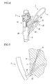
- FIG. 1 is a plan view illustrating a drainage tube retainer according to a first embodiment of the present invention.
- FIG. 2 is a cross-section illustrating a drainage tube retainer according to the first embodiment of the present invention in detail.
- FIG. 3 is a plan view illustrating a drainage tube retained in a human body by the drainage tube retainer according to the first embodiment of the present invention.
- FIG. 4 is a schematic diagram illustrating how to use the drainage tube retainer according to the first embodiment of the present invention.
- FIG. 5 is a schematic diagram illustrating how to use the drainage tube retainer according to the first embodiment of the present invention.
- FIG. 6 is a schematic diagram illustrating how to use the drainage tube retainer according to the first embodiment of the present invention.
- FIG. 7 is a schematic diagram illustrating how to use the drainage tube retainer according to the first embodiment of the present invention.
- FIG. 8 is a schematic diagram illustrating how to use the drainage tube retainer according to the first embodiment of the present invention.
- FIG. 9 is a plan view illustrating a guide cathether constituting the drainage tube retainer according to a second embodiment of the present invention.
- FIG. 10 is a cross-section illustrating the guide cathether constituting the drainage tube retainer according to the second embodiment of the present invention.
- FIG. 11 is a plan view illustrating a pusher tube constituting the drainage tube retainer according to a second embodiment of the present invention.
- FIG. 12 is a schematic diagram illustrating how to use the drainage tube retainer according to the second embodiment of the present invention.
- FIG. 13 is a schematic diagram illustrating how to use the drainage tube retainer according to the second embodiment of the present invention.
- FIG. 14 is a schematic diagram illustrating how to use the drainage tube retainer according to the second embodiment of the present invention.
- FIG. 15 is a schematic diagram illustrating how to use the drainage tube retainer according to the second embodiment of the present invention.
- FIG. 16 is a schematic diagram illustrating how to use the drainage tube retainer according to the second embodiment of the present invention.
- FIG. 17 is a schematic diagram illustrating how to use the drainage tube retainer according to the second embodiment of the present invention.
- FIG. 18 is a schematic diagram illustrating how to use the drainage tube retainer according to the second embodiment of the present invention.
- FIG. 19 illustrates a first modified example of the drainage tube.
- FIG. 20 is a schematic diagram for illustrating how to use the drainage tube shown in FIG. 19.
- FIG. 21 illustrates a second modified example of the drainage tube.
- FIG. 22 is a schematic diagram for illustrating how to use the drainage tube shown in FIG. 21.
- FIG. 23 is a schematic diagram for illustrating an inappropriate usage of the drainage tube.
- FIG. 24 is a schematic diagram for illustrating an appropriate usage of the drainage tube shown in FIG. 21.
-
- 1, 30:
- drainage tube retainer (endoscopic treatment instrument)
- 2:
- endoscope
- 3:
- endoscope port
- 5:
- guidewire
- 10, 32:
- guide cathether (elongated section)
- 11:
- pusher tube (hollow section)
- 13, 37:
- pusher cap (connecting section)
- 15, 31:
- cap
- 16:
- hook (engagement member)
- 22:
- endoscope adapter
- A first embodiment of the present invention will be explained with reference to FIGS. 1 to 8.
As illustrated in FIGS. 1 to 7, a drainage tube retainer (endoscopic treatment instrument) 1 according to the present embodiment is an instrument retained in aconstriction 8 in abile duct 7, etc. Thedrainage tube retainer 1 can extend and retract in a channel not shown in the drawings along aguidewire 5 inserted in the channel from anendoscope port 3 of anendoscope 2. Provided to thedrainage tube retainer 1 are a guide cathether (elongated section) 10; a pusher tube (elongated section) 11; a pusher cap (connecting section) 13; and acap 15. - The
guide catheter 10 fitted to thedrainage tube 6 so as to be inserted in thedrainage tube 6 slidably supports thedrainage tube 6. Theguidewire 5 is inserted through theguide catheter 10.
Thepusher tube 11 fitted to theguide catheter 10 so as to pass theguide catheter 10 therethrough is slidably supported by theguide catheter 10. - The
pusher cap 13 provided to a proximal end of thepusher tube 11 positions the proximal end of thepusher tube 11 relative to anoperation section 12 of theendoscope 2 so that a direction in which thepusher tube 11 is inserted into the channel substantially coincides with a direction in which theguide catheter 10 is retracted from thepusher tube 11.
Thecap 15 is provided to a proximal end of theguide catheter 10. - The
guide catheter 10 is considerably longer than the total length of thepusher tube 11 and thedrainage tube 6 so that the distal end of theguide catheter 10 protrudes ahead of thedrainage tube 6 when theguide catheter 10 is fitted to thepusher tube 11 and further fitted to thedrainage tube 6 disposed ahead of the distal end of thepusher tube 11.
Provided to thepusher cap 13 is an approximately C-shaped and elastically deformable hook (engagement member) 16. Thehook 16 is formed to have its distal end directed toward the distal end of thepusher tube 11.
Provided to the proximal end of thepusher cap 13 is amale thread section 17. Detachably provided to the distal end of thecap 15 is afemale thread section 18 that engages with themale thread section 17. - As illustrated in FIG. 3, disposed to both ends of the
drainage tube 6 areflaps flaps bile duct 7 and engage to living body organs so as to prevent thedrainage tube 6 from misaligning.
Amark 21 indicating a manufacturing lot number or a model number, etc., of thedrainage tube 6 is printed in the vicinity of one of theflaps flap 20B, that is disposed nearer to theendoscope 2 when thedrainage tube 6 is retained in the body ("4XK" is printed in the example illustrated in FIG. 3.). - Detachably attached to the
operation section 12 of theendoscope 2 is anendoscopic adapter 22 that rotatively supports thehook 16 of thepusher cap 13. Theendoscopic adapter 22 is provided with anadapter body 23, a cylindricaltreatment instrument fixture 25, and anendoscope fixture 26. Ahook 16 slidably engages to thetreatment instrument fixture 25 provided to an end of theadapter body 23. Provided to the other end of theadapter body 23 is the approximatelycylindrical endoscope fixture 26 in which a part of the cylindrical fixture is notched. - A method, function, and effect according to the present embodiment will be explained next regarding the retaining of the
drainage tube 6 with thedrainage tube retainer 1.
As illustrated in FIG. 4, an insertion section of theendoscope 2 is first inserted into a body cavity so as to reach the distal end into the vicinity of a duodenal papilla. Consequently theguidewire 5 is inserted into a channel not shown in the drawing from theendoscope port 3 of theendoscope 2 so as to be inserted through theconstriction 8 of thebile duct 7. - Consequently, the
endoscope fixture 26 of theendoscopic adapter 22 is attached at a predetermined position of theoperation section 12 of theendoscope 2. The distal end of theguide catheter 10 fitted to thedrainage tube 6 and thepusher tube 11 is fitted to theguidewire 5 so that the proximal end of theguidewire 5 protruding from theendoscope port 3 is inserted in theguide catheter 10. Then a part of thedrainage tube 6 and a part of thepusher tube 11 are inserted through the channel.
As illustrated in FIG. 4, theguidewire 5, theguide catheter 10 fitted to theguidewire 5 , and thepusher tube 11 fitted to theguide catheter 10 are folded together at some midpoints thereof them in the vicinity of theendoscope port 3. Thehook 16 is then hung on thetreatment instrument fixture 25 of theendoscopic adapter 22. Accordingly thehook 16 is adjustably rotated on thetreatment instrument fixture 25 so that thecap 15 faces theendoscope port 3 and so that thepusher tube 11 and theguidewire 5 having protruded from thecap 15 are disposed substantially in parallel. Since a direction in which thepusher tube 11 and theguide catheter 10 fitted to thepusher tube 11 are inserted into the channel from theendoscope port 3 substantially coincides with a direction in which theguidewire 5 is retracted from theguide catheter 10, the endoscopist can conduct an operation of inserting thepusher tube 11 and theguide catheter 10 into the channel from theendoscope port 3 and an operation of retracting theguidewire 5 from theguide catheter 10 simultaneously by a single-handed manipulation. - Grasping with the endoscopist's hand and moving together this state of the
pusher tube 11, theguide catheter 10, and theguidewire 5 in a direction indicated by an arrow illustrated in the drawing permit thepusher tube 11 and theguide catheter 10 to be inserted through the channel. On the other hand, theguidewire 5 is retracted from theguide catheter 10 by the length equal to an insertion length of thepusher tube 11 and theguide catheter 10. To be more specific, apparently theguidewire 5 remains at a predetermined position in the channel, and only thepusher tube 11 and theguide catheter 10 are inserted through the channel along theguidewire 5. As illustrated in FIG. 5, repeating the above operations permits thepusher tube 11 and theguide catheter 10 to be inserted through the channel while the distal end of theguidewire 5 remains at the predetermined position and permits the distal end of theguide catheter 10 to move to a desirable position. - As illustrated in FIG. 6, the
cap 15 is rotated relative to thepusher cap 13 so as to remove thecap 15 from thepusher cap 13.
As illustrated in FIG. 7, thecap 15 is grasped and theguide catheter 10 and theguidewire 5 fitted to theguide catheter 10 are retracted from thepusher cap 13 so that theguide catheter 10 and thepusher tube 11 that have protruded from thepusher cap 13 are substantially parallel in the vicinity of theendoscope port 3. Since a direction in which thepusher tube 11 is inserted into the channel from theendoscope port 3 substantially coincides with a direction in which theguide catheter 10 and theguidewire 5 are retracted from theguide catheter 11, the endoscopist can conduct an operation of inserting thepusher tube 11 into the channel from theendoscope port 3 and an operation of retracting theguide catheter 10 and theguidewire 5 from thepusher tube 11 simultaneously by a single-handed manipulation. - Grasping with the endoscopist's hand and moving together this state of the
guide catheter 10, theguidewire 5, and thepusher tube 11 in a direction indicated by an arrow illustrated in the drawing permit thepusher tube 11 to be inserted through the channel.
On the other hand, theguide catheter 10 and theguidewire 5 are retracted from thepusher tube 11 by the length equal to an insertion length of thepusher tube 11. To be more specific, apparently theguide catheter 10 and theguidewire 5 remain at predetermined positions in the channel, and only thepusher tube 11 is inserted through the channel along theguide catheter 10. As illustrated in FIG. 8, repeating the above operations permits thepusher tube 11 to be inserted through the channel while the distal end of theguide catheter 10 and the distal end of theguidewire 5 remain at the predetermined positions, and permits the distal end of thepusher tube 11 to move to a desirable position. Thedrainage tube 11 is pushed toward the distal end of thepusher tube 11 to be inserted through thebile duct 7. - Retracting the
guide catheter 10, thepusher tube 11, and theguidewire 5 from thebile duct 7 and detaching them from theendoscope 2 eventually allow thedrainage tube 6 to be retained in thebile duct 7. - The
endoscopic adapter 22 attached to theoperation section 12 of theendoscope 2 permits the proximal end of thepusher tube 11 of the abovedrainage tube retainer 1 to be fixed separately from theoperation section 12 of theendoscope 2 by a predetermined distance and to be directed toward theendoscope port 3. - In addition, the
pusher cap 13 having the elasticallydeformable hook 16 can be positioned and engaged at a round surface part of thetreatment instrument fixture 25. Furthermore, thepusher cap 13 can be rotated relative to theendoscope 2 in a direction along an arch of the substantially C-shapedhook 16.
Theguidewire 5, theguide catheter 10, and thepusher tube 11 can be folded in the vicinity of theendoscope port 3; therefore, theguidewire 5 can be disposed substantially in parallel with theguide catheter 10 and thepusher tube 11. This allows the direction in which thepusher tube 11 and theguide catheter 10 are inserted through the channel from theendoscope port 3 to substantially coincide with the direction in which theguidewire 5 is retracted from theguide catheter 10. This furthermore allows the direction in which thepusher tube 11 is inserted through the channel from theendoscope port 3 to substantially coincide with the direction in which theguide catheter 10 and theguidewire 5 are retracted from thepusher tube 11. - This results in allowing the endoscopist alone having connected the
cap 15 to thepusher cap 13 to conduct the operation of inserting two tubes, i.e., theguide catheter 10 and thepusher tube 11 fitted to theguide catheter 10 into the channel along theguidewire 5 while the distal end of theguidewire 5 is retained at a certain position. Also, the endoscopist alone having detached thecap 15 from thepusher cap 13 can conduct the operation of inserting thedrainage tube 6 and thepusher tube 11 through the channel along theguidewire 5 and theguide catheter 10 while the distal end of theguidewire 5 and the distal end of theguide catheter 10 are retained at certain positions. - Also, the
mark 21 indicating a manufacturing lot number, etc., printed not on a package but directly on thedrainage tube 6 allows information including the manufacturing lot numbers, etc. of thedrainage tube 6 that has been retained in a body. - A second embodiment of the present invention will be explained next with reference to FIGS. 9 to 18. Note that elements that are equivalent to those of the above first embodiment will be assigned the same reference symbols, and redundant explanations thereof will be omitted.
Provided to adrainage tube retainer 30 according to the present embodiment is acap 31 detachable from aguide catheter 32. Provided to thecap 31 are ahub 33, aplunger 35, and an O-ring 36. Provided to thehub 33 is a through-hole 31A through which aguide catheter 32 can penetrate. Also, provided to thehub 33 is ahook 16. Provided to a proximal end of thehub 33 is ascrew hole 33A. The inner diameter of thescrew hole 33A is greater than that of the through-hole 31A. Afemale thread section 18 is formed on the surface of thescrew hole 33A. Provided to a distal end of theplunger 35 is aprotruding screw section 35A. Amale thread section 17 that engages with thefemale thread section 18 of thescrew hole 33A is formed on an outer surface of the protrudingscrew section 35A that protrudes from theplunger 35 toward thescrew hole 33A of thehub 33. - The size of the O-
ring 36, i.e., the outer diameter thereof enables it to be inserted in thescrew hole 33A. The O-ring 36 crushed between a bottom section of thescrew hole 33A in thehub 33 and a distal end of the protrudingscrew section 35A elastically deforms so as to engage with the outer surface of theguide catheter 32. Aflange section 38 is provided to the proximal end of thepusher cap 37 in place of themale thread section 17. - A method, function, and effect according to the present embodiment will be explained next regarding the retaining of the
drainage tube 6 with thedrainage tube retainer 30.
To begin with, as illustrated in FIG. 13, an insertion section of theendoscope 2 is inserted into a body cavity so as to reach the distal end into the vicinity of a duodenal papilla. Consequently theguidewire 5 is inserted into a channel not shown in the drawing from aendoscope port 3 of theendoscope 2 so as to be inserted through aconstriction 8 of abile duct 7. - Consequently, the
endoscope fixture 26 of theendoscopic adapter 22 is attached at a predetermined position of theoperation section 12 of theendoscope 2. The distal end of theguide catheter 32 is fitted to theguidewire 5 so that the proximal end of theguidewire 5 having protruded from theendoscope port 3 is inserted in theguide catheter 32; thus, a part of theguide catheter 32 is consequently inserted in the channel.
As illustrated in FIG. 12, theguidewire 5 and theguide catheter 32 fitted to theguidewire 5 are folded together at some midpoints thereof in the vicinity of theendoscope port 3. Thehook 16 of thecap 31 is then hung on thetreatment instrument fixture 25 of theendoscopic adapter 22. Accordingly, thehook 16 is adjustably rotated on thetreatment instrument fixture 25 so that thecap 31 faces theendoscope port 3 and so that theguide catheter 32 and theguidewire 5 having protruded from thecap 31 are disposed substantially in parallel. Since a direction in which theguide catheter 32 is inserted into the channel from theendoscope port 3 substantially coincides with a direction in which theguidewire 5 is retracted from theguide catheter 32, the endoscopist can conduct an operation of inserting theguide catheter 32 into the channel from theendoscope port 3 and an operation of retracting theguidewire 5 from theguide catheter 32 simultaneously by a single-handed manipulation. - Grasping with the endoscopist's hand and moving together this state of the
guide catheter 32 and theguidewire 5 in a direction indicated by an arrow illustrated in the drawing permit theguide catheter 32 to be inserted through the channel. On the other hand, theguidewire 5 is retracted from theguide catheter 32 by the length equal to an insertion length of theguide catheter 32. To be more specific, apparently theguidewire 5 remains at a predetermined position in the channel, and only thepusher tube 32 is inserted through the channel along theguidewire 5. As illustrated in FIG. 13, repeating the above operations permits theguide catheter 32 to be inserted through the channel while the distal end of theguidewire 5 remains at the predetermined position, and permits the distal end of theguide catheter 32 to move to a desirable position. - Consequently, the
hook 16 of thecap 31 is detached from thetreatment instrument fixture 25 of theendoscopic adapter 22 as illustrated in FIG. 16. Theplunger 35 is then separated from thehub 33 by rotating theplunger 35 relative to thehub 33 as illustrated in FIG. 15. Separating theplunger 35 from thehub 33 releases the engagement between theguide catheter 32 and the O-ring 36; thus, thecap 31 is detached from theguide catheter 32. - Consequently the proximal end of the
guide catheter 32 is inserted through thedrainage tube 6 and further inserted through thepusher tube 11 as illustrated in FIG. 16. Theguide catheter 32 and thepusher tube 11 are folded together at some midpoints thereof in the vicinity of theendoscope port 3. Thehook 16 of thepusher cap 37 is then hung on thetreatment instrument fixture 25 of theendoscopic adapter 22. Accordingly thehook 16 is adjustably rotated on thetreatment instrument fixture 25 so that, as illustrated in FIG. 17, thecap pusher cap 37 faces theendoscope port 3 and so that thepusher tube 11 and theguide catheter 32 having protruded from thepusher cap 37 are disposed substantially in parallel. Since a direction in which thepusher tube 11 is inserted into the channel from theendoscope port 3 substantially coincides with a direction in which theguide catheter 32 is retracted from thepusher tube 11, the endoscopist can conduct an operation of inserting thepusher tube 11 into the channel from theendoscope port 3 and an operation of retracting theguide catheter 32 from thepusher tube 11 simultaneously by a single-handed manipulation. - Grasping with the endoscopist's hand and moving together this state of the 9 and the
guide catheter 32 in a direction indicated by an arrow illustrated in the drawing permit thepusher tube 11 to be inserted through the channel. On the other hand, theguide catheter 32 is retracted from thepusher tube 11 by the length equal to an insertion length of thepusher tube 11. To be more specific, apparently theguide catheter 32 remains at a predetermined position in the channel, and only thepusher tube 11 is inserted through the channel along theguide catheter 32. As illustrated in FIG. 18, repeating the above operations permits thepusher tube 11 to be inserted through the channel while the distal end of theguide catheter 32 remains at the predetermined position, and permits the distal end of thepusher tube 11 to move to a desirable position. Thedrainage tube 11 is pushed toward the distal end of the 9 to be inserted through thebile duct 7. - Retracting the
guide catheter 32, thepusher tube 11, and theguidewire 5 from thebile duct 7 and detaching them from theendoscope 2 eventually allow thedrainage tube 11 to be retained in thebile duct 7. - The
drainage tube retainer 30 provides thedrainage tube 11 and thepusher tube 11 over theguide catheter 32, detached from thecap 31, not only from the distal end but also from the proximal end, thereby a wide selection of manipulation can be obtained. - In addition, the
endoscopic adapter 22 attached to theoperation section 12 of theendoscope 2 permits the proximal end of theguide catheter 32 to be fixed separately from theoperation section 12 of theendoscope 2 by a predetermined distance and to be directed toward theendoscope port 3 similarly to the first embodiment.
Theguidewire 5 and theguide catheter 32 can be folded together at some midpoints thereof in the vicinity of theendoscope port 3; therefore, theguidewire 5 can be disposed substantially in parallel with theguide catheter 32. This allows the direction in which theguide catheter 32 is inserted through the channel from theendoscope port 3 to substantially coincide with the direction in which theguidewire 5 is retracted from theguide catheter 32. This furthermore allows the direction in which thepusher tube 11 is inserted through the channel from theendoscope port 3 to substantially coincide with the direction in which theguide catheter 32 is retracted from thepusher tube 11. - This results in allowing the endoscopist alone to conduct the operation of inserting the
guide catheter 32 into the channel along theguidewire 5 while the distal end theguidewire 5 is retained at a certain position. Also, the endoscopist alone having detached thecap 31 can conduct the operation of inserting thedrainage tube 6 and thepusher tube 11 through the channel along theguidewire 5 and theguide catheter 32 while the distal end of theguidewire 5 and the distal end of theguide catheter 32 are retained at certain positions. - The technical scope of the present invention is not limited to the embodiments described above. Rather, various modifications may be added provided as long as they do not depart from the spirit of the invention.
For example, thedrainage tube retainers endoscopic adapter 22 is attached to theoperation section 12 of theendoscope 2. Note that thehook 16 may be attached without using theendoscopic adapter 22, i.e., directly at a predetermined position of theoperation section 12 of theendoscope 2. - Also, as illustrated in FIG. 19, the
mark 21 of thedrainage tube 40 may be printed at the proximal end of thedrainage tube 40 disposed nearer to theendoscope 2 when thedrainage tube 40 is disposed in the body. As illustrated in FIG. 19, the mark after the retention of thedrainage tube 40 can be observed by using the endoscope if the proximal end of thedrainage tube 40 is previously protruded. - Furthermore, as illustrated in FIG. 21, the
mark 21 of thedrainage tube 41 may be disposed in the vicinity of the distal end, e.g., a position indicated by a broken line in the drawing, of theflap 20B that is disposed nearer to theendoscope 2 when thedrainage tube 40 is retained in the body. - In ordinary cases, the
drainage tube 41 is disposed so that adistal end flap 20A expands beyond theconstriction 8 of thebile duct 7 and aproximal end flap 20B expands in a duodenum. As illustrated in FIG. 22, theproximal end flap 20B of thedrainage tube 41 can be observed when it is extracted from the distal end of theendoscope 2. Accordingly, the proximal end flap is prevented from being inserted into thebile duct 7 due to the excessivelyextended drainage tube 41 as illustrated in FIG. 23; thus, thedrainage tube 41 can be retained at a predetermined position as illustrated in FIG. 24. Industrial Applicability - The present invention relates to an endoscopic treatment instrument inserted through a channel of an endoscope from an endoscope port that includes: an elongated section for slidably supporting a retainer retained in a live organ through the channel; a hollow section disposed in the exterior of the elongated section and slidably supported by the elongated section; and a connecting section provided to the hollow section for positioning the hollow section relative to the endoscope so that a direction in which the hollow section is inserted through the channel substantially coincides with a direction in which the hollow section is retracted from the hollow section. The present invention allows an endoscopist alone to slide a hollow section along an elongated section so that the elongated section that is inserted in the hollow section is retained at a certain position.
Claims (8)
- An endoscopic treatment instrument inserted through a channel of an endoscope from an endoscope port, the endoscopic treatment instrument comprising:an elongated section for slidably supporting a retainer retained in a live organ through the channel;a hollow section disposed in the exterior of the elongated section and slidably supported by the elongated section; anda connecting section provided to the hollow section for positioning the hollow section relative to the endoscope so that a direction in which the hollow section is inserted through the channel substantially coincides with a direction in which the hollow section is retracted from the hollow section.
- The endoscopic treatment instrument according to Claim 1, wherein the elongated section is capable of sliding along a guidewire inserted through the channel.
- The endoscopic treatment instrument according to one of Claims 1 and 2, wherein the connecting section is provided with an elastically deformable, approximately C-shaped engagement member.
- The endoscopic treatment instrument according to one of Claims 1 to 3 , wherein the connecting section attached to the endoscope via an endoscope adapter attached to an operation section of the endoscope for rotatively supporting the connecting section is detachable.
- The endoscopic treatment instrument according to one of Claims 1 to 4 , further comprising a cap disposed at a proximal end of the elongated section, wherein the cap is detachable from the connecting section.
- The endoscopic treatment instrument according to one of Claims 1 to 4 , further comprising a cap disposed at a proximal end of the elongated section, wherein the cap is detachable from the elongated section.
- The endoscopic treatment instrument according to one of Claims 5 and 6 , wherein the cap is provided with the elastically deformable, approximately C-shaped engagement member.
- The endoscopic treatment instrument according to one of Claims 5 to 7 , wherein the cap is detachable from the endoscope via the endoscope adapter attached to the operation section of the endoscope so as to rotatively support the cap.
Applications Claiming Priority (2)
| Application Number | Priority Date | Filing Date | Title |
|---|---|---|---|
| JP2005019346A JP2006204476A (en) | 2005-01-27 | 2005-01-27 | Operative appliance for endoscope |
| PCT/JP2006/300725 WO2006080231A1 (en) | 2005-01-27 | 2006-01-19 | Treatment instrument for endoscope |
Publications (2)
| Publication Number | Publication Date |
|---|---|
| EP1842499A1 true EP1842499A1 (en) | 2007-10-10 |
| EP1842499A4 EP1842499A4 (en) | 2015-09-23 |
Family
ID=36740265
Family Applications (1)
| Application Number | Title | Priority Date | Filing Date |
|---|---|---|---|
| EP06711971.9A Withdrawn EP1842499A4 (en) | 2005-01-27 | 2006-01-19 | Treatment instrument for endoscope |
Country Status (4)
| Country | Link |
|---|---|
| US (1) | US20090221870A1 (en) |
| EP (1) | EP1842499A4 (en) |
| JP (1) | JP2006204476A (en) |
| WO (1) | WO2006080231A1 (en) |
Cited By (5)
| Publication number | Priority date | Publication date | Assignee | Title |
|---|---|---|---|---|
| EP2508120A1 (en) * | 2006-03-23 | 2012-10-10 | Boston Scientific Limited | Medical devices and systems |
| US8608649B2 (en) | 2004-03-23 | 2013-12-17 | Boston Scientific Scimed, Inc. | In-vivo visualization system |
| CN104605965A (en) * | 2015-01-30 | 2015-05-13 | 科塞尔医疗科技(苏州)有限公司 | Anti-displacement esophageal stent apparatus bag |
| US9215970B2 (en) | 2004-08-09 | 2015-12-22 | Boston Scientific Scimed, Inc. | Fiber optic imaging catheter |
| US11819192B2 (en) | 2004-03-23 | 2023-11-21 | Boston Scientific Scimed, Inc. | In-vivo visualization system |
Families Citing this family (4)
| Publication number | Priority date | Publication date | Assignee | Title |
|---|---|---|---|---|
| CN105979895B (en) * | 2014-03-04 | 2019-12-06 | 奥林巴斯株式会社 | Endoscope treatment system and treatment tool for endoscope |
| WO2015146321A1 (en) * | 2014-03-26 | 2015-10-01 | オリンパス株式会社 | Stent delivery system and endoscope system |
| WO2016092982A1 (en) * | 2014-12-10 | 2016-06-16 | オリンパス株式会社 | Assist tool and endoscope system |
| CN110769736B (en) * | 2017-05-17 | 2023-01-13 | 奥瑞斯健康公司 | Replaceable working channel |
Family Cites Families (10)
| Publication number | Priority date | Publication date | Assignee | Title |
|---|---|---|---|---|
| US5571085A (en) * | 1995-03-24 | 1996-11-05 | Electro-Catheter Corporation | Steerable open lumen catheter |
| US5527280A (en) * | 1995-03-29 | 1996-06-18 | The Children's Seashore House | Multi-lumen enteral feeding and medicating device |
| US5964740A (en) * | 1996-07-09 | 1999-10-12 | Asahi Kogaku Kogyo Kabushiki Kaisha | Treatment accessory for an endoscope |
| US6096009A (en) * | 1996-09-13 | 2000-08-01 | Boston Scientific Corporation | Guidewire and catheter locking device and method |
| US5921952A (en) * | 1997-08-14 | 1999-07-13 | Boston Scientific Corporation | Drainage catheter delivery system |
| JP3315931B2 (en) * | 1998-01-05 | 2002-08-19 | 旭光学工業株式会社 | Drainage tube indwelling device for endoscope |
| JP4175693B2 (en) * | 1998-06-15 | 2008-11-05 | オリンパス株式会社 | Endoscope treatment instrument insertion / extraction device |
| JP2000152985A (en) * | 1998-11-20 | 2000-06-06 | Olympus Optical Co Ltd | Manipulator for endoscope |
| JP2004049891A (en) * | 2002-05-29 | 2004-02-19 | Olympus Corp | Endoscope apparatus |
| JP2004143617A (en) * | 2002-10-23 | 2004-05-20 | Katsumi:Kk | Method for producing translucent paper and translucent paper produced by the method |
-
2005
- 2005-01-27 JP JP2005019346A patent/JP2006204476A/en active Pending
-
2006
- 2006-01-19 EP EP06711971.9A patent/EP1842499A4/en not_active Withdrawn
- 2006-01-19 US US11/814,662 patent/US20090221870A1/en not_active Abandoned
- 2006-01-19 WO PCT/JP2006/300725 patent/WO2006080231A1/en active Application Filing
Non-Patent Citations (1)
| Title |
|---|
| See references of WO2006080231A1 * |
Cited By (9)
| Publication number | Priority date | Publication date | Assignee | Title |
|---|---|---|---|---|
| US8608649B2 (en) | 2004-03-23 | 2013-12-17 | Boston Scientific Scimed, Inc. | In-vivo visualization system |
| US9339173B2 (en) | 2004-03-23 | 2016-05-17 | Boston Scientific Scimed, Inc. | In-vivo visualization system |
| US11064869B2 (en) | 2004-03-23 | 2021-07-20 | Boston Scientific Scimed, Inc. | In-vivo visualization system |
| US11819192B2 (en) | 2004-03-23 | 2023-11-21 | Boston Scientific Scimed, Inc. | In-vivo visualization system |
| US11832793B2 (en) | 2004-03-23 | 2023-12-05 | Boston Scientific Scimed, Inc. | Vivo visualization system |
| US9215970B2 (en) | 2004-08-09 | 2015-12-22 | Boston Scientific Scimed, Inc. | Fiber optic imaging catheter |
| US10058236B2 (en) | 2004-08-09 | 2018-08-28 | Boston Scientific Scimed, Inc. | Fiber optic imaging catheter |
| EP2508120A1 (en) * | 2006-03-23 | 2012-10-10 | Boston Scientific Limited | Medical devices and systems |
| CN104605965A (en) * | 2015-01-30 | 2015-05-13 | 科塞尔医疗科技(苏州)有限公司 | Anti-displacement esophageal stent apparatus bag |
Also Published As
| Publication number | Publication date |
|---|---|
| EP1842499A4 (en) | 2015-09-23 |
| JP2006204476A (en) | 2006-08-10 |
| WO2006080231A1 (en) | 2006-08-03 |
| US20090221870A1 (en) | 2009-09-03 |
Similar Documents
| Publication | Publication Date | Title |
|---|---|---|
| EP1842499A1 (en) | Treatment instrument for endoscope | |
| EP1854500B1 (en) | Treatment tool inserting/withdrawing auxiliary device | |
| US8133265B2 (en) | Guide catheter, and stent delivery system | |
| EP1641402B1 (en) | Handle for medical devices, and medical device assemblies including a handle | |
| CN101057775B (en) | Endoscopic ancillary attachment devices | |
| US20130289351A1 (en) | Combination Endoscopic Operative Delivery System | |
| CN109310274B (en) | Wire locking assembly | |
| JP2013509244A (en) | Balloon catheter with removable hub and method for the balloon catheter | |
| JPH119696A (en) | Catheter system | |
| CA2582918C (en) | Medical snaring device | |
| US8956340B2 (en) | Urethral catheter assembly with a guide wire | |
| US20170265892A1 (en) | Introducer Sheaths for Endoscopes and Related Methods | |
| US10888308B2 (en) | Tissue collector | |
| US8142449B2 (en) | Device for inserting at least one anchor piece into a hollow space of a living being | |
| EP3329858A1 (en) | Tissue recovery tool and tissue recovery system | |
| ES2384203T3 (en) | Guide wire fixing | |
| ES2822090T3 (en) | Gripper forceps tool | |
| JP5752740B2 (en) | Endoscopic sliding tube | |
| WO2010068739A1 (en) | Clip for handling an endoscopic device | |
| US20210121055A1 (en) | Endoscope system, curved needle delivery system, and curved needle delivery method | |
| WO2013109624A2 (en) | Probe-based confocal laser endomicroscopy | |
| JP2009131398A (en) | Mounting assisting tool of balloon for endoscope, mounting kit of balloon for endoscope, and endoscope system | |
| WO2014093007A1 (en) | Urethral catheter assembly with a guide wire | |
| CN216933377U (en) | Clamping device for minimally invasive surgery | |
| CN212816202U (en) | Gastrointestinal endoscope sleeve assembly |
Legal Events
| Date | Code | Title | Description |
|---|---|---|---|
| PUAI | Public reference made under article 153(3) epc to a published international application that has entered the european phase |
Free format text: ORIGINAL CODE: 0009012 |
|
| 17P | Request for examination filed |
Effective date: 20070802 |
|
| AK | Designated contracting states |
Kind code of ref document: A1 Designated state(s): DE FR GB IE |
|
| DAX | Request for extension of the european patent (deleted) | ||
| RBV | Designated contracting states (corrected) |
Designated state(s): DE FR GB IE |
|
| RA4 | Supplementary search report drawn up and despatched (corrected) |
Effective date: 20150821 |
|
| RIC1 | Information provided on ipc code assigned before grant |
Ipc: A61F 2/95 20130101ALN20150817BHEP Ipc: A61B 17/34 20060101ALI20150817BHEP Ipc: A61B 17/00 20060101ALN20150817BHEP Ipc: A61B 1/018 20060101ALN20150817BHEP Ipc: A61B 19/00 20060101ALN20150817BHEP Ipc: A61F 2/04 20130101ALN20150817BHEP Ipc: A61M 1/00 20060101ALI20150817BHEP Ipc: A61B 1/00 20060101AFI20150817BHEP |
|
| STAA | Information on the status of an ep patent application or granted ep patent |
Free format text: STATUS: THE APPLICATION IS DEEMED TO BE WITHDRAWN |
|
| RAP1 | Party data changed (applicant data changed or rights of an application transferred) |
Owner name: OLYMPUS CORPORATION |
|
| 18D | Application deemed to be withdrawn |
Effective date: 20160319 |
|
| RAP1 | Party data changed (applicant data changed or rights of an application transferred) |
Owner name: OLYMPUS CORPORATION |