EP1845895B1 - Apparatus for deploying an implantable device within the body - Google Patents
Apparatus for deploying an implantable device within the body Download PDFInfo
- Publication number
- EP1845895B1 EP1845895B1 EP06717905.1A EP06717905A EP1845895B1 EP 1845895 B1 EP1845895 B1 EP 1845895B1 EP 06717905 A EP06717905 A EP 06717905A EP 1845895 B1 EP1845895 B1 EP 1845895B1
- Authority
- EP
- European Patent Office
- Prior art keywords
- stent
- lumen
- side branch
- catheter
- string
- Prior art date
- Legal status (The legal status is an assumption and is not a legal conclusion. Google has not performed a legal analysis and makes no representation as to the accuracy of the status listed.)
- Not-in-force
Links
- 230000007246 mechanism Effects 0.000 claims description 17
- 239000012530 fluid Substances 0.000 claims description 7
- 238000011010 flushing procedure Methods 0.000 claims description 4
- 239000007943 implant Substances 0.000 description 67
- 238000000034 method Methods 0.000 description 44
- 239000000463 material Substances 0.000 description 40
- 210000002376 aorta thoracic Anatomy 0.000 description 29
- 210000004027 cell Anatomy 0.000 description 27
- 238000002513 implantation Methods 0.000 description 27
- 210000001519 tissue Anatomy 0.000 description 26
- 210000002744 extracellular matrix Anatomy 0.000 description 25
- 210000001367 artery Anatomy 0.000 description 22
- 210000005166 vasculature Anatomy 0.000 description 19
- 230000017531 blood circulation Effects 0.000 description 17
- 102000010834 Extracellular Matrix Proteins Human genes 0.000 description 16
- 108010037362 Extracellular Matrix Proteins Proteins 0.000 description 16
- 210000004204 blood vessel Anatomy 0.000 description 14
- 210000000709 aorta Anatomy 0.000 description 13
- 210000004876 tela submucosa Anatomy 0.000 description 13
- 210000002469 basement membrane Anatomy 0.000 description 11
- 239000008280 blood Substances 0.000 description 11
- 210000004369 blood Anatomy 0.000 description 11
- 239000010410 layer Substances 0.000 description 11
- BASFCYQUMIYNBI-UHFFFAOYSA-N platinum Chemical compound [Pt] BASFCYQUMIYNBI-UHFFFAOYSA-N 0.000 description 10
- 230000002792 vascular Effects 0.000 description 10
- 210000001765 aortic valve Anatomy 0.000 description 9
- 210000002168 brachiocephalic trunk Anatomy 0.000 description 9
- 230000001225 therapeutic effect Effects 0.000 description 9
- 210000003932 urinary bladder Anatomy 0.000 description 9
- 206010002329 Aneurysm Diseases 0.000 description 8
- 238000003384 imaging method Methods 0.000 description 8
- 238000004519 manufacturing process Methods 0.000 description 7
- 238000013519 translation Methods 0.000 description 7
- 239000004480 active ingredient Substances 0.000 description 6
- 210000003484 anatomy Anatomy 0.000 description 6
- 238000013461 design Methods 0.000 description 6
- 210000002919 epithelial cell Anatomy 0.000 description 6
- 210000001105 femoral artery Anatomy 0.000 description 6
- 210000003090 iliac artery Anatomy 0.000 description 6
- 238000002608 intravascular ultrasound Methods 0.000 description 6
- 239000000203 mixture Substances 0.000 description 6
- -1 polyethylene Polymers 0.000 description 6
- FAPWRFPIFSIZLT-UHFFFAOYSA-M Sodium chloride Chemical compound [Na+].[Cl-] FAPWRFPIFSIZLT-UHFFFAOYSA-M 0.000 description 5
- 230000008901 benefit Effects 0.000 description 5
- 210000001168 carotid artery common Anatomy 0.000 description 5
- 238000011065 in-situ storage Methods 0.000 description 5
- 230000005012 migration Effects 0.000 description 5
- 238000013508 migration Methods 0.000 description 5
- 229910001000 nickel titanium Inorganic materials 0.000 description 5
- 210000000056 organ Anatomy 0.000 description 5
- 229910052697 platinum Inorganic materials 0.000 description 5
- 230000008439 repair process Effects 0.000 description 5
- 239000011780 sodium chloride Substances 0.000 description 5
- 210000003270 subclavian artery Anatomy 0.000 description 5
- 239000000758 substrate Substances 0.000 description 5
- 238000007514 turning Methods 0.000 description 5
- 239000003795 chemical substances by application Substances 0.000 description 4
- 238000000576 coating method Methods 0.000 description 4
- 238000004891 communication Methods 0.000 description 4
- 210000002808 connective tissue Anatomy 0.000 description 4
- 239000003814 drug Substances 0.000 description 4
- 210000000981 epithelium Anatomy 0.000 description 4
- PCHJSUWPFVWCPO-UHFFFAOYSA-N gold Chemical compound [Au] PCHJSUWPFVWCPO-UHFFFAOYSA-N 0.000 description 4
- 229910052737 gold Inorganic materials 0.000 description 4
- 239000010931 gold Substances 0.000 description 4
- 230000002439 hemostatic effect Effects 0.000 description 4
- 229910052751 metal Inorganic materials 0.000 description 4
- 239000002184 metal Substances 0.000 description 4
- 210000004877 mucosa Anatomy 0.000 description 4
- 210000002784 stomach Anatomy 0.000 description 4
- 238000004804 winding Methods 0.000 description 4
- 102000008186 Collagen Human genes 0.000 description 3
- 108010035532 Collagen Proteins 0.000 description 3
- WQZGKKKJIJFFOK-GASJEMHNSA-N Glucose Natural products OC[C@H]1OC(O)[C@H](O)[C@@H](O)[C@@H]1O WQZGKKKJIJFFOK-GASJEMHNSA-N 0.000 description 3
- 230000008321 arterial blood flow Effects 0.000 description 3
- 239000002473 artificial blood Substances 0.000 description 3
- QVGXLLKOCUKJST-UHFFFAOYSA-N atomic oxygen Chemical compound [O] QVGXLLKOCUKJST-UHFFFAOYSA-N 0.000 description 3
- 230000008859 change Effects 0.000 description 3
- 239000011248 coating agent Substances 0.000 description 3
- 229920001436 collagen Polymers 0.000 description 3
- 210000004207 dermis Anatomy 0.000 description 3
- 201000010099 disease Diseases 0.000 description 3
- 208000037265 diseases, disorders, signs and symptoms Diseases 0.000 description 3
- 229940079593 drug Drugs 0.000 description 3
- 239000000975 dye Substances 0.000 description 3
- 230000010102 embolization Effects 0.000 description 3
- 239000008103 glucose Substances 0.000 description 3
- 210000000936 intestine Anatomy 0.000 description 3
- 210000004185 liver Anatomy 0.000 description 3
- HLXZNVUGXRDIFK-UHFFFAOYSA-N nickel titanium Chemical compound [Ti].[Ti].[Ti].[Ti].[Ti].[Ti].[Ti].[Ti].[Ti].[Ti].[Ti].[Ni].[Ni].[Ni].[Ni].[Ni].[Ni].[Ni].[Ni].[Ni].[Ni].[Ni].[Ni].[Ni].[Ni] HLXZNVUGXRDIFK-UHFFFAOYSA-N 0.000 description 3
- 239000001301 oxygen Substances 0.000 description 3
- 229910052760 oxygen Inorganic materials 0.000 description 3
- 239000000843 powder Substances 0.000 description 3
- 230000008569 process Effects 0.000 description 3
- 210000003491 skin Anatomy 0.000 description 3
- 210000000813 small intestine Anatomy 0.000 description 3
- 239000000243 solution Substances 0.000 description 3
- 229910001220 stainless steel Inorganic materials 0.000 description 3
- 239000010935 stainless steel Substances 0.000 description 3
- 239000000126 substance Substances 0.000 description 3
- 208000019553 vascular disease Diseases 0.000 description 3
- 238000012800 visualization Methods 0.000 description 3
- IJGRMHOSHXDMSA-UHFFFAOYSA-N Atomic nitrogen Chemical compound N#N IJGRMHOSHXDMSA-UHFFFAOYSA-N 0.000 description 2
- 208000001750 Endoleak Diseases 0.000 description 2
- 102000004190 Enzymes Human genes 0.000 description 2
- 108090000790 Enzymes Proteins 0.000 description 2
- PXHVJJICTQNCMI-UHFFFAOYSA-N Nickel Chemical compound [Ni] PXHVJJICTQNCMI-UHFFFAOYSA-N 0.000 description 2
- 102100037599 SPARC Human genes 0.000 description 2
- 101710100111 SPARC Proteins 0.000 description 2
- 206010064396 Stent-graft endoleak Diseases 0.000 description 2
- 208000007536 Thrombosis Diseases 0.000 description 2
- HZEWFHLRYVTOIW-UHFFFAOYSA-N [Ti].[Ni] Chemical compound [Ti].[Ni] HZEWFHLRYVTOIW-UHFFFAOYSA-N 0.000 description 2
- 208000002223 abdominal aortic aneurysm Diseases 0.000 description 2
- 238000005299 abrasion Methods 0.000 description 2
- 238000004873 anchoring Methods 0.000 description 2
- 210000000702 aorta abdominal Anatomy 0.000 description 2
- 208000007474 aortic aneurysm Diseases 0.000 description 2
- TZCXTZWJZNENPQ-UHFFFAOYSA-L barium sulfate Chemical compound [Ba+2].[O-]S([O-])(=O)=O TZCXTZWJZNENPQ-UHFFFAOYSA-L 0.000 description 2
- 230000000903 blocking effect Effects 0.000 description 2
- 230000036772 blood pressure Effects 0.000 description 2
- 230000001413 cellular effect Effects 0.000 description 2
- 238000002591 computed tomography Methods 0.000 description 2
- 230000002526 effect on cardiovascular system Effects 0.000 description 2
- 230000000694 effects Effects 0.000 description 2
- 230000003511 endothelial effect Effects 0.000 description 2
- 229940088598 enzyme Drugs 0.000 description 2
- 230000007717 exclusion Effects 0.000 description 2
- 238000002594 fluoroscopy Methods 0.000 description 2
- 230000006870 function Effects 0.000 description 2
- 238000000227 grinding Methods 0.000 description 2
- 210000003709 heart valve Anatomy 0.000 description 2
- 230000000968 intestinal effect Effects 0.000 description 2
- 239000004816 latex Substances 0.000 description 2
- 229920000126 latex Polymers 0.000 description 2
- 239000011159 matrix material Substances 0.000 description 2
- 238000005259 measurement Methods 0.000 description 2
- 210000004379 membrane Anatomy 0.000 description 2
- 239000012528 membrane Substances 0.000 description 2
- 150000002739 metals Chemical class 0.000 description 2
- 210000004400 mucous membrane Anatomy 0.000 description 2
- 230000037361 pathway Effects 0.000 description 2
- 238000002360 preparation method Methods 0.000 description 2
- 102000004196 processed proteins & peptides Human genes 0.000 description 2
- 108090000765 processed proteins & peptides Proteins 0.000 description 2
- 230000009467 reduction Effects 0.000 description 2
- 210000002254 renal artery Anatomy 0.000 description 2
- 210000002460 smooth muscle Anatomy 0.000 description 2
- 239000007787 solid Substances 0.000 description 2
- 210000000130 stem cell Anatomy 0.000 description 2
- 239000000725 suspension Substances 0.000 description 2
- 229910052715 tantalum Inorganic materials 0.000 description 2
- GUVRBAGPIYLISA-UHFFFAOYSA-N tantalum atom Chemical compound [Ta] GUVRBAGPIYLISA-UHFFFAOYSA-N 0.000 description 2
- XLYOFNOQVPJJNP-UHFFFAOYSA-N water Substances O XLYOFNOQVPJJNP-UHFFFAOYSA-N 0.000 description 2
- 238000009941 weaving Methods 0.000 description 2
- TUSDEZXZIZRFGC-UHFFFAOYSA-N 1-O-galloyl-3,6-(R)-HHDP-beta-D-glucose Natural products OC1C(O2)COC(=O)C3=CC(O)=C(O)C(O)=C3C3=C(O)C(O)=C(O)C=C3C(=O)OC1C(O)C2OC(=O)C1=CC(O)=C(O)C(O)=C1 TUSDEZXZIZRFGC-UHFFFAOYSA-N 0.000 description 1
- 108020000948 Antisense Oligonucleotides Proteins 0.000 description 1
- BSYNRYMUTXBXSQ-UHFFFAOYSA-N Aspirin Chemical compound CC(=O)OC1=CC=CC=C1C(O)=O BSYNRYMUTXBXSQ-UHFFFAOYSA-N 0.000 description 1
- 108010006654 Bleomycin Proteins 0.000 description 1
- 241000283690 Bos taurus Species 0.000 description 1
- XDTMQSROBMDMFD-UHFFFAOYSA-N C1CCCCC1 Chemical compound C1CCCCC1 XDTMQSROBMDMFD-UHFFFAOYSA-N 0.000 description 1
- 102000016289 Cell Adhesion Molecules Human genes 0.000 description 1
- 108010067225 Cell Adhesion Molecules Proteins 0.000 description 1
- 229940123587 Cell cycle inhibitor Drugs 0.000 description 1
- 206010053567 Coagulopathies Diseases 0.000 description 1
- 229910000684 Cobalt-chrome Inorganic materials 0.000 description 1
- 229920004934 Dacron® Polymers 0.000 description 1
- 239000001263 FEMA 3042 Substances 0.000 description 1
- 102000009123 Fibrin Human genes 0.000 description 1
- 108010073385 Fibrin Proteins 0.000 description 1
- BWGVNKXGVNDBDI-UHFFFAOYSA-N Fibrin monomer Chemical compound CNC(=O)CNC(=O)CN BWGVNKXGVNDBDI-UHFFFAOYSA-N 0.000 description 1
- 102000008946 Fibrinogen Human genes 0.000 description 1
- 108010049003 Fibrinogen Proteins 0.000 description 1
- 102000016359 Fibronectins Human genes 0.000 description 1
- 108010067306 Fibronectins Proteins 0.000 description 1
- 102000003886 Glycoproteins Human genes 0.000 description 1
- 108090000288 Glycoproteins Proteins 0.000 description 1
- HTTJABKRGRZYRN-UHFFFAOYSA-N Heparin Chemical compound OC1C(NC(=O)C)C(O)OC(COS(O)(=O)=O)C1OC1C(OS(O)(=O)=O)C(O)C(OC2C(C(OS(O)(=O)=O)C(OC3C(C(O)C(O)C(O3)C(O)=O)OS(O)(=O)=O)C(CO)O2)NS(O)(=O)=O)C(C(O)=O)O1 HTTJABKRGRZYRN-UHFFFAOYSA-N 0.000 description 1
- 108090000100 Hepatocyte Growth Factor Proteins 0.000 description 1
- 102000003745 Hepatocyte Growth Factor Human genes 0.000 description 1
- 241000124008 Mammalia Species 0.000 description 1
- 229930192392 Mitomycin Natural products 0.000 description 1
- NWIBSHFKIJFRCO-WUDYKRTCSA-N Mytomycin Chemical compound C1N2C(C(C(C)=C(N)C3=O)=O)=C3[C@@H](COC(N)=O)[C@@]2(OC)[C@@H]2[C@H]1N2 NWIBSHFKIJFRCO-WUDYKRTCSA-N 0.000 description 1
- MWUXSHHQAYIFBG-UHFFFAOYSA-N Nitric oxide Chemical class O=[N] MWUXSHHQAYIFBG-UHFFFAOYSA-N 0.000 description 1
- 229930012538 Paclitaxel Natural products 0.000 description 1
- 241001494479 Pecora Species 0.000 description 1
- LRBQNJMCXXYXIU-PPKXGCFTSA-N Penta-digallate-beta-D-glucose Natural products OC1=C(O)C(O)=CC(C(=O)OC=2C(=C(O)C=C(C=2)C(=O)OC[C@@H]2[C@H]([C@H](OC(=O)C=3C=C(OC(=O)C=4C=C(O)C(O)=C(O)C=4)C(O)=C(O)C=3)[C@@H](OC(=O)C=3C=C(OC(=O)C=4C=C(O)C(O)=C(O)C=4)C(O)=C(O)C=3)[C@H](OC(=O)C=3C=C(OC(=O)C=4C=C(O)C(O)=C(O)C=4)C(O)=C(O)C=3)O2)OC(=O)C=2C=C(OC(=O)C=3C=C(O)C(O)=C(O)C=3)C(O)=C(O)C=2)O)=C1 LRBQNJMCXXYXIU-PPKXGCFTSA-N 0.000 description 1
- 102000057297 Pepsin A Human genes 0.000 description 1
- 108090000284 Pepsin A Proteins 0.000 description 1
- 108091005804 Peptidases Proteins 0.000 description 1
- 239000004698 Polyethylene Substances 0.000 description 1
- 239000004365 Protease Substances 0.000 description 1
- 102000016611 Proteoglycans Human genes 0.000 description 1
- 108010067787 Proteoglycans Proteins 0.000 description 1
- 102100037486 Reverse transcriptase/ribonuclease H Human genes 0.000 description 1
- BQCADISMDOOEFD-UHFFFAOYSA-N Silver Chemical compound [Ag] BQCADISMDOOEFD-UHFFFAOYSA-N 0.000 description 1
- 108010023197 Streptokinase Proteins 0.000 description 1
- 102000002938 Thrombospondin Human genes 0.000 description 1
- 108060008245 Thrombospondin Proteins 0.000 description 1
- GWEVSGVZZGPLCZ-UHFFFAOYSA-N Titan oxide Chemical compound O=[Ti]=O GWEVSGVZZGPLCZ-UHFFFAOYSA-N 0.000 description 1
- RTAQQCXQSZGOHL-UHFFFAOYSA-N Titanium Chemical compound [Ti] RTAQQCXQSZGOHL-UHFFFAOYSA-N 0.000 description 1
- 102000004142 Trypsin Human genes 0.000 description 1
- 108090000631 Trypsin Proteins 0.000 description 1
- 108090000435 Urokinase-type plasminogen activator Proteins 0.000 description 1
- 102000003990 Urokinase-type plasminogen activator Human genes 0.000 description 1
- 241000251539 Vertebrata <Metazoa> Species 0.000 description 1
- WAIPAZQMEIHHTJ-UHFFFAOYSA-N [Cr].[Co] Chemical compound [Cr].[Co] WAIPAZQMEIHHTJ-UHFFFAOYSA-N 0.000 description 1
- 230000003187 abdominal effect Effects 0.000 description 1
- 235000011054 acetic acid Nutrition 0.000 description 1
- 229960001138 acetylsalicylic acid Drugs 0.000 description 1
- 239000002253 acid Substances 0.000 description 1
- 230000009471 action Effects 0.000 description 1
- 239000000853 adhesive Substances 0.000 description 1
- 230000001070 adhesive effect Effects 0.000 description 1
- 229910045601 alloy Inorganic materials 0.000 description 1
- 239000000956 alloy Substances 0.000 description 1
- 230000033115 angiogenesis Effects 0.000 description 1
- 230000002491 angiogenic effect Effects 0.000 description 1
- 238000002583 angiography Methods 0.000 description 1
- 229940045799 anthracyclines and related substance Drugs 0.000 description 1
- 239000003242 anti bacterial agent Substances 0.000 description 1
- 229940088710 antibiotic agent Drugs 0.000 description 1
- 239000003146 anticoagulant agent Substances 0.000 description 1
- 239000003080 antimitotic agent Substances 0.000 description 1
- 229940127218 antiplatelet drug Drugs 0.000 description 1
- 239000000074 antisense oligonucleotide Substances 0.000 description 1
- 238000012230 antisense oligonucleotides Methods 0.000 description 1
- WQZGKKKJIJFFOK-VFUOTHLCSA-N beta-D-glucose Chemical compound OC[C@H]1O[C@@H](O)[C@H](O)[C@@H](O)[C@@H]1O WQZGKKKJIJFFOK-VFUOTHLCSA-N 0.000 description 1
- 230000002146 bilateral effect Effects 0.000 description 1
- 239000000560 biocompatible material Substances 0.000 description 1
- 230000015572 biosynthetic process Effects 0.000 description 1
- WMWLMWRWZQELOS-UHFFFAOYSA-N bismuth(III) oxide Inorganic materials O=[Bi]O[Bi]=O WMWLMWRWZQELOS-UHFFFAOYSA-N 0.000 description 1
- OYVAGSVQBOHSSS-UAPAGMARSA-O bleomycin A2 Chemical class N([C@H](C(=O)N[C@H](C)[C@@H](O)[C@H](C)C(=O)N[C@@H]([C@H](O)C)C(=O)NCCC=1SC=C(N=1)C=1SC=C(N=1)C(=O)NCCC[S+](C)C)[C@@H](O[C@H]1[C@H]([C@@H](O)[C@H](O)[C@H](CO)O1)O[C@@H]1[C@H]([C@@H](OC(N)=O)[C@H](O)[C@@H](CO)O1)O)C=1N=CNC=1)C(=O)C1=NC([C@H](CC(N)=O)NC[C@H](N)C(N)=O)=NC(N)=C1C OYVAGSVQBOHSSS-UAPAGMARSA-O 0.000 description 1
- 210000004556 brain Anatomy 0.000 description 1
- 230000002612 cardiopulmonary effect Effects 0.000 description 1
- 210000001715 carotid artery Anatomy 0.000 description 1
- 230000021164 cell adhesion Effects 0.000 description 1
- 210000003850 cellular structure Anatomy 0.000 description 1
- 239000004568 cement Substances 0.000 description 1
- 238000003486 chemical etching Methods 0.000 description 1
- 239000013626 chemical specie Substances 0.000 description 1
- 230000035602 clotting Effects 0.000 description 1
- 239000010952 cobalt-chrome Substances 0.000 description 1
- 229960005188 collagen Drugs 0.000 description 1
- 150000001875 compounds Chemical class 0.000 description 1
- 239000000994 contrast dye Substances 0.000 description 1
- 239000002872 contrast media Substances 0.000 description 1
- 210000004087 cornea Anatomy 0.000 description 1
- 210000004351 coronary vessel Anatomy 0.000 description 1
- 229940072645 coumadin Drugs 0.000 description 1
- 230000008878 coupling Effects 0.000 description 1
- 238000010168 coupling process Methods 0.000 description 1
- 238000005859 coupling reaction Methods 0.000 description 1
- 238000005520 cutting process Methods 0.000 description 1
- GVJHHUAWPYXKBD-UHFFFAOYSA-N d-alpha-tocopherol Natural products OC1=C(C)C(C)=C2OC(CCCC(C)CCCC(C)CCCC(C)C)(C)CCC2=C1C GVJHHUAWPYXKBD-UHFFFAOYSA-N 0.000 description 1
- 239000000412 dendrimer Substances 0.000 description 1
- 229920000736 dendritic polymer Polymers 0.000 description 1
- 230000001419 dependent effect Effects 0.000 description 1
- 238000011161 development Methods 0.000 description 1
- 229960003957 dexamethasone Drugs 0.000 description 1
- UREBDLICKHMUKA-CXSFZGCWSA-N dexamethasone Chemical compound C1CC2=CC(=O)C=C[C@]2(C)[C@]2(F)[C@@H]1[C@@H]1C[C@@H](C)[C@@](C(=O)CO)(O)[C@@]1(C)C[C@@H]2O UREBDLICKHMUKA-CXSFZGCWSA-N 0.000 description 1
- 229960004833 dexamethasone phosphate Drugs 0.000 description 1
- VQODGRNSFPNSQE-CXSFZGCWSA-N dexamethasone phosphate Chemical compound C1CC2=CC(=O)C=C[C@]2(C)[C@]2(F)[C@@H]1[C@@H]1C[C@@H](C)[C@@](C(=O)COP(O)(O)=O)(O)[C@@]1(C)C[C@@H]2O VQODGRNSFPNSQE-CXSFZGCWSA-N 0.000 description 1
- 238000003745 diagnosis Methods 0.000 description 1
- 238000009792 diffusion process Methods 0.000 description 1
- 238000007598 dipping method Methods 0.000 description 1
- 229940042399 direct acting antivirals protease inhibitors Drugs 0.000 description 1
- 238000002224 dissection Methods 0.000 description 1
- 238000001035 drying Methods 0.000 description 1
- 230000009977 dual effect Effects 0.000 description 1
- 238000005868 electrolysis reaction Methods 0.000 description 1
- 239000003792 electrolyte Substances 0.000 description 1
- 239000008151 electrolyte solution Substances 0.000 description 1
- 238000009713 electroplating Methods 0.000 description 1
- 229910000701 elgiloys (Co-Cr-Ni Alloy) Inorganic materials 0.000 description 1
- 210000003038 endothelium Anatomy 0.000 description 1
- 238000005516 engineering process Methods 0.000 description 1
- 230000006862 enzymatic digestion Effects 0.000 description 1
- 230000002255 enzymatic effect Effects 0.000 description 1
- 230000002327 eosinophilic effect Effects 0.000 description 1
- 230000003628 erosive effect Effects 0.000 description 1
- 210000003238 esophagus Anatomy 0.000 description 1
- 238000005530 etching Methods 0.000 description 1
- 239000000835 fiber Substances 0.000 description 1
- 102000013373 fibrillar collagen Human genes 0.000 description 1
- 108060002894 fibrillar collagen Proteins 0.000 description 1
- 229950003499 fibrin Drugs 0.000 description 1
- 229940012952 fibrinogen Drugs 0.000 description 1
- 210000000630 fibrocyte Anatomy 0.000 description 1
- 238000007667 floating Methods 0.000 description 1
- 150000002344 gold compounds Chemical class 0.000 description 1
- 210000004013 groin Anatomy 0.000 description 1
- 230000012010 growth Effects 0.000 description 1
- 238000009998 heat setting Methods 0.000 description 1
- 229960002897 heparin Drugs 0.000 description 1
- 229920000669 heparin Polymers 0.000 description 1
- 239000012456 homogeneous solution Substances 0.000 description 1
- KIUKXJAPPMFGSW-MNSSHETKSA-N hyaluronan Chemical compound CC(=O)N[C@H]1[C@H](O)O[C@H](CO)[C@@H](O)C1O[C@H]1[C@H](O)[C@@H](O)[C@H](O[C@H]2[C@@H](C(O[C@H]3[C@@H]([C@@H](O)[C@H](O)[C@H](O3)C(O)=O)O)[C@H](O)[C@@H](CO)O2)NC(C)=O)[C@@H](C(O)=O)O1 KIUKXJAPPMFGSW-MNSSHETKSA-N 0.000 description 1
- 229940099552 hyaluronan Drugs 0.000 description 1
- 229920002674 hyaluronan Polymers 0.000 description 1
- 230000036571 hydration Effects 0.000 description 1
- 238000006703 hydration reaction Methods 0.000 description 1
- XMBWDFGMSWQBCA-UHFFFAOYSA-N hydrogen iodide Chemical compound I XMBWDFGMSWQBCA-UHFFFAOYSA-N 0.000 description 1
- 238000007654 immersion Methods 0.000 description 1
- 229940125721 immunosuppressive agent Drugs 0.000 description 1
- 239000004615 ingredient Substances 0.000 description 1
- 238000003780 insertion Methods 0.000 description 1
- 230000037431 insertion Effects 0.000 description 1
- 238000009434 installation Methods 0.000 description 1
- PNDPGZBMCMUPRI-UHFFFAOYSA-N iodine Chemical compound II PNDPGZBMCMUPRI-UHFFFAOYSA-N 0.000 description 1
- 208000028867 ischemia Diseases 0.000 description 1
- 210000003734 kidney Anatomy 0.000 description 1
- 238000003698 laser cutting Methods 0.000 description 1
- 239000007788 liquid Substances 0.000 description 1
- 238000011068 loading method Methods 0.000 description 1
- 238000003754 machining Methods 0.000 description 1
- 229910000734 martensite Inorganic materials 0.000 description 1
- 239000003771 matrix metalloproteinase inhibitor Substances 0.000 description 1
- 229940121386 matrix metalloproteinase inhibitor Drugs 0.000 description 1
- 235000013372 meat Nutrition 0.000 description 1
- 210000004249 mesenteric artery inferior Anatomy 0.000 description 1
- 210000001363 mesenteric artery superior Anatomy 0.000 description 1
- 229910001092 metal group alloy Inorganic materials 0.000 description 1
- 229910021645 metal ion Inorganic materials 0.000 description 1
- CFCUWKMKBJTWLW-BKHRDMLASA-N mithramycin Chemical compound O([C@@H]1C[C@@H](O[C@H](C)[C@H]1O)OC=1C=C2C=C3C[C@H]([C@@H](C(=O)C3=C(O)C2=C(O)C=1C)O[C@@H]1O[C@H](C)[C@@H](O)[C@H](O[C@@H]2O[C@H](C)[C@H](O)[C@H](O[C@@H]3O[C@H](C)[C@@H](O)[C@@](C)(O)C3)C2)C1)[C@H](OC)C(=O)[C@@H](O)[C@@H](C)O)[C@H]1C[C@@H](O)[C@H](O)[C@@H](C)O1 CFCUWKMKBJTWLW-BKHRDMLASA-N 0.000 description 1
- 229960004857 mitomycin Drugs 0.000 description 1
- KKZJGLLVHKMTCM-UHFFFAOYSA-N mitoxantrone Chemical compound O=C1C2=C(O)C=CC(O)=C2C(=O)C2=C1C(NCCNCCO)=CC=C2NCCNCCO KKZJGLLVHKMTCM-UHFFFAOYSA-N 0.000 description 1
- 229960001156 mitoxantrone Drugs 0.000 description 1
- 230000007935 neutral effect Effects 0.000 description 1
- 229910052759 nickel Inorganic materials 0.000 description 1
- 229910052758 niobium Inorganic materials 0.000 description 1
- 239000010955 niobium Substances 0.000 description 1
- GUCVJGMIXFAOAE-UHFFFAOYSA-N niobium atom Chemical compound [Nb] GUCVJGMIXFAOAE-UHFFFAOYSA-N 0.000 description 1
- 239000002840 nitric oxide donor Substances 0.000 description 1
- 229910052757 nitrogen Inorganic materials 0.000 description 1
- RVTZCBVAJQQJTK-UHFFFAOYSA-N oxygen(2-);zirconium(4+) Chemical compound [O-2].[O-2].[Zr+4] RVTZCBVAJQQJTK-UHFFFAOYSA-N 0.000 description 1
- 229960001592 paclitaxel Drugs 0.000 description 1
- 206010033675 panniculitis Diseases 0.000 description 1
- 239000002245 particle Substances 0.000 description 1
- 239000011238 particulate composite Substances 0.000 description 1
- 229940111202 pepsin Drugs 0.000 description 1
- 239000000137 peptide hydrolase inhibitor Substances 0.000 description 1
- 230000010412 perfusion Effects 0.000 description 1
- 230000035699 permeability Effects 0.000 description 1
- 239000002831 pharmacologic agent Substances 0.000 description 1
- 230000000144 pharmacologic effect Effects 0.000 description 1
- 239000004033 plastic Substances 0.000 description 1
- 229920003023 plastic Polymers 0.000 description 1
- 239000000106 platelet aggregation inhibitor Substances 0.000 description 1
- 229960003171 plicamycin Drugs 0.000 description 1
- 238000005498 polishing Methods 0.000 description 1
- 229920000728 polyester Polymers 0.000 description 1
- 229920000573 polyethylene Polymers 0.000 description 1
- 239000005020 polyethylene terephthalate Substances 0.000 description 1
- 229920000642 polymer Polymers 0.000 description 1
- 229920001296 polysiloxane Polymers 0.000 description 1
- 229920002635 polyurethane Polymers 0.000 description 1
- 239000004814 polyurethane Substances 0.000 description 1
- 229940124606 potential therapeutic agent Drugs 0.000 description 1
- 230000035755 proliferation Effects 0.000 description 1
- 230000017854 proteolysis Effects 0.000 description 1
- 210000003102 pulmonary valve Anatomy 0.000 description 1
- 230000000541 pulsatile effect Effects 0.000 description 1
- 238000010298 pulverizing process Methods 0.000 description 1
- 238000010791 quenching Methods 0.000 description 1
- 210000002321 radial artery Anatomy 0.000 description 1
- 230000005855 radiation Effects 0.000 description 1
- 230000002040 relaxant effect Effects 0.000 description 1
- 238000007634 remodeling Methods 0.000 description 1
- 208000037803 restenosis Diseases 0.000 description 1
- 238000005096 rolling process Methods 0.000 description 1
- 150000003839 salts Chemical class 0.000 description 1
- 238000007790 scraping Methods 0.000 description 1
- 238000000926 separation method Methods 0.000 description 1
- 238000010008 shearing Methods 0.000 description 1
- 229910052709 silver Inorganic materials 0.000 description 1
- 239000004332 silver Substances 0.000 description 1
- 210000004872 soft tissue Anatomy 0.000 description 1
- 239000002904 solvent Substances 0.000 description 1
- 230000000087 stabilizing effect Effects 0.000 description 1
- 238000010186 staining Methods 0.000 description 1
- 239000007858 starting material Substances 0.000 description 1
- 230000002966 stenotic effect Effects 0.000 description 1
- 230000003637 steroidlike Effects 0.000 description 1
- 229960005202 streptokinase Drugs 0.000 description 1
- 210000004304 subcutaneous tissue Anatomy 0.000 description 1
- 239000002344 surface layer Substances 0.000 description 1
- 238000001356 surgical procedure Methods 0.000 description 1
- 230000009885 systemic effect Effects 0.000 description 1
- 229920002258 tannic acid Polymers 0.000 description 1
- LRBQNJMCXXYXIU-NRMVVENXSA-N tannic acid Chemical compound OC1=C(O)C(O)=CC(C(=O)OC=2C(=C(O)C=C(C=2)C(=O)OC[C@@H]2[C@H]([C@H](OC(=O)C=3C=C(OC(=O)C=4C=C(O)C(O)=C(O)C=4)C(O)=C(O)C=3)[C@@H](OC(=O)C=3C=C(OC(=O)C=4C=C(O)C(O)=C(O)C=4)C(O)=C(O)C=3)[C@@H](OC(=O)C=3C=C(OC(=O)C=4C=C(O)C(O)=C(O)C=4)C(O)=C(O)C=3)O2)OC(=O)C=2C=C(OC(=O)C=3C=C(O)C(O)=C(O)C=3)C(O)=C(O)C=2)O)=C1 LRBQNJMCXXYXIU-NRMVVENXSA-N 0.000 description 1
- 229940033123 tannic acid Drugs 0.000 description 1
- 235000015523 tannic acid Nutrition 0.000 description 1
- RCINICONZNJXQF-MZXODVADSA-N taxol Chemical compound O([C@@H]1[C@@]2(C[C@@H](C(C)=C(C2(C)C)[C@H](C([C@]2(C)[C@@H](O)C[C@H]3OC[C@]3([C@H]21)OC(C)=O)=O)OC(=O)C)OC(=O)[C@H](O)[C@@H](NC(=O)C=1C=CC=CC=1)C=1C=CC=CC=1)O)C(=O)C1=CC=CC=C1 RCINICONZNJXQF-MZXODVADSA-N 0.000 description 1
- 239000004753 textile Substances 0.000 description 1
- 230000002537 thrombolytic effect Effects 0.000 description 1
- 230000008467 tissue growth Effects 0.000 description 1
- 229910052719 titanium Inorganic materials 0.000 description 1
- 239000010936 titanium Substances 0.000 description 1
- OGIDPMRJRNCKJF-UHFFFAOYSA-N titanium oxide Inorganic materials [Ti]=O OGIDPMRJRNCKJF-UHFFFAOYSA-N 0.000 description 1
- 229960001295 tocopherol Drugs 0.000 description 1
- 229930003799 tocopherol Natural products 0.000 description 1
- 235000010384 tocopherol Nutrition 0.000 description 1
- 239000011732 tocopherol Substances 0.000 description 1
- 238000003325 tomography Methods 0.000 description 1
- 239000012588 trypsin Substances 0.000 description 1
- WFKWXMTUELFFGS-UHFFFAOYSA-N tungsten Chemical compound [W] WFKWXMTUELFFGS-UHFFFAOYSA-N 0.000 description 1
- 229910052721 tungsten Inorganic materials 0.000 description 1
- 239000010937 tungsten Substances 0.000 description 1
- 210000003954 umbilical cord Anatomy 0.000 description 1
- 229960005356 urokinase Drugs 0.000 description 1
- 230000007556 vascular defect Effects 0.000 description 1
- 230000024883 vasodilation Effects 0.000 description 1
- 210000001631 vena cava inferior Anatomy 0.000 description 1
- 210000002620 vena cava superior Anatomy 0.000 description 1
- 210000002073 venous valve Anatomy 0.000 description 1
- PJVWKTKQMONHTI-UHFFFAOYSA-N warfarin Chemical compound OC=1C2=CC=CC=C2OC(=O)C=1C(CC(=O)C)C1=CC=CC=C1 PJVWKTKQMONHTI-UHFFFAOYSA-N 0.000 description 1
- 238000010618 wire wrap Methods 0.000 description 1
- 229910001928 zirconium oxide Inorganic materials 0.000 description 1
- GVJHHUAWPYXKBD-IEOSBIPESA-N α-tocopherol Chemical compound OC1=C(C)C(C)=C2O[C@@](CCC[C@H](C)CCC[C@H](C)CCCC(C)C)(C)CCC2=C1C GVJHHUAWPYXKBD-IEOSBIPESA-N 0.000 description 1
Images


Classifications
-
- A—HUMAN NECESSITIES
- A61—MEDICAL OR VETERINARY SCIENCE; HYGIENE
- A61F—FILTERS IMPLANTABLE INTO BLOOD VESSELS; PROSTHESES; DEVICES PROVIDING PATENCY TO, OR PREVENTING COLLAPSING OF, TUBULAR STRUCTURES OF THE BODY, e.g. STENTS; ORTHOPAEDIC, NURSING OR CONTRACEPTIVE DEVICES; FOMENTATION; TREATMENT OR PROTECTION OF EYES OR EARS; BANDAGES, DRESSINGS OR ABSORBENT PADS; FIRST-AID KITS
- A61F2/00—Filters implantable into blood vessels; Prostheses, i.e. artificial substitutes or replacements for parts of the body; Appliances for connecting them with the body; Devices providing patency to, or preventing collapsing of, tubular structures of the body, e.g. stents
- A61F2/95—Instruments specially adapted for placement or removal of stents or stent-grafts
- A61F2/954—Instruments specially adapted for placement or removal of stents or stent-grafts for placing stents or stent-grafts in a bifurcation
-
- A—HUMAN NECESSITIES
- A61—MEDICAL OR VETERINARY SCIENCE; HYGIENE
- A61F—FILTERS IMPLANTABLE INTO BLOOD VESSELS; PROSTHESES; DEVICES PROVIDING PATENCY TO, OR PREVENTING COLLAPSING OF, TUBULAR STRUCTURES OF THE BODY, e.g. STENTS; ORTHOPAEDIC, NURSING OR CONTRACEPTIVE DEVICES; FOMENTATION; TREATMENT OR PROTECTION OF EYES OR EARS; BANDAGES, DRESSINGS OR ABSORBENT PADS; FIRST-AID KITS
- A61F2/00—Filters implantable into blood vessels; Prostheses, i.e. artificial substitutes or replacements for parts of the body; Appliances for connecting them with the body; Devices providing patency to, or preventing collapsing of, tubular structures of the body, e.g. stents
- A61F2/02—Prostheses implantable into the body
- A61F2/04—Hollow or tubular parts of organs, e.g. bladders, tracheae, bronchi or bile ducts
- A61F2/06—Blood vessels
-
- A—HUMAN NECESSITIES
- A61—MEDICAL OR VETERINARY SCIENCE; HYGIENE
- A61F—FILTERS IMPLANTABLE INTO BLOOD VESSELS; PROSTHESES; DEVICES PROVIDING PATENCY TO, OR PREVENTING COLLAPSING OF, TUBULAR STRUCTURES OF THE BODY, e.g. STENTS; ORTHOPAEDIC, NURSING OR CONTRACEPTIVE DEVICES; FOMENTATION; TREATMENT OR PROTECTION OF EYES OR EARS; BANDAGES, DRESSINGS OR ABSORBENT PADS; FIRST-AID KITS
- A61F2/00—Filters implantable into blood vessels; Prostheses, i.e. artificial substitutes or replacements for parts of the body; Appliances for connecting them with the body; Devices providing patency to, or preventing collapsing of, tubular structures of the body, e.g. stents
- A61F2/82—Devices providing patency to, or preventing collapsing of, tubular structures of the body, e.g. stents
- A61F2/844—Devices providing patency to, or preventing collapsing of, tubular structures of the body, e.g. stents folded prior to deployment
-
- A—HUMAN NECESSITIES
- A61—MEDICAL OR VETERINARY SCIENCE; HYGIENE
- A61F—FILTERS IMPLANTABLE INTO BLOOD VESSELS; PROSTHESES; DEVICES PROVIDING PATENCY TO, OR PREVENTING COLLAPSING OF, TUBULAR STRUCTURES OF THE BODY, e.g. STENTS; ORTHOPAEDIC, NURSING OR CONTRACEPTIVE DEVICES; FOMENTATION; TREATMENT OR PROTECTION OF EYES OR EARS; BANDAGES, DRESSINGS OR ABSORBENT PADS; FIRST-AID KITS
- A61F2/00—Filters implantable into blood vessels; Prostheses, i.e. artificial substitutes or replacements for parts of the body; Appliances for connecting them with the body; Devices providing patency to, or preventing collapsing of, tubular structures of the body, e.g. stents
- A61F2/82—Devices providing patency to, or preventing collapsing of, tubular structures of the body, e.g. stents
- A61F2/856—Single tubular stent with a side portal passage
-
- A—HUMAN NECESSITIES
- A61—MEDICAL OR VETERINARY SCIENCE; HYGIENE
- A61F—FILTERS IMPLANTABLE INTO BLOOD VESSELS; PROSTHESES; DEVICES PROVIDING PATENCY TO, OR PREVENTING COLLAPSING OF, TUBULAR STRUCTURES OF THE BODY, e.g. STENTS; ORTHOPAEDIC, NURSING OR CONTRACEPTIVE DEVICES; FOMENTATION; TREATMENT OR PROTECTION OF EYES OR EARS; BANDAGES, DRESSINGS OR ABSORBENT PADS; FIRST-AID KITS
- A61F2/00—Filters implantable into blood vessels; Prostheses, i.e. artificial substitutes or replacements for parts of the body; Appliances for connecting them with the body; Devices providing patency to, or preventing collapsing of, tubular structures of the body, e.g. stents
- A61F2/82—Devices providing patency to, or preventing collapsing of, tubular structures of the body, e.g. stents
- A61F2/86—Stents in a form characterised by the wire-like elements; Stents in the form characterised by a net-like or mesh-like structure
- A61F2/90—Stents in a form characterised by the wire-like elements; Stents in the form characterised by a net-like or mesh-like structure characterised by a net-like or mesh-like structure
-
- A—HUMAN NECESSITIES
- A61—MEDICAL OR VETERINARY SCIENCE; HYGIENE
- A61F—FILTERS IMPLANTABLE INTO BLOOD VESSELS; PROSTHESES; DEVICES PROVIDING PATENCY TO, OR PREVENTING COLLAPSING OF, TUBULAR STRUCTURES OF THE BODY, e.g. STENTS; ORTHOPAEDIC, NURSING OR CONTRACEPTIVE DEVICES; FOMENTATION; TREATMENT OR PROTECTION OF EYES OR EARS; BANDAGES, DRESSINGS OR ABSORBENT PADS; FIRST-AID KITS
- A61F2/00—Filters implantable into blood vessels; Prostheses, i.e. artificial substitutes or replacements for parts of the body; Appliances for connecting them with the body; Devices providing patency to, or preventing collapsing of, tubular structures of the body, e.g. stents
- A61F2/95—Instruments specially adapted for placement or removal of stents or stent-grafts
-
- A—HUMAN NECESSITIES
- A61—MEDICAL OR VETERINARY SCIENCE; HYGIENE
- A61F—FILTERS IMPLANTABLE INTO BLOOD VESSELS; PROSTHESES; DEVICES PROVIDING PATENCY TO, OR PREVENTING COLLAPSING OF, TUBULAR STRUCTURES OF THE BODY, e.g. STENTS; ORTHOPAEDIC, NURSING OR CONTRACEPTIVE DEVICES; FOMENTATION; TREATMENT OR PROTECTION OF EYES OR EARS; BANDAGES, DRESSINGS OR ABSORBENT PADS; FIRST-AID KITS
- A61F2/00—Filters implantable into blood vessels; Prostheses, i.e. artificial substitutes or replacements for parts of the body; Appliances for connecting them with the body; Devices providing patency to, or preventing collapsing of, tubular structures of the body, e.g. stents
- A61F2/02—Prostheses implantable into the body
- A61F2/24—Heart valves ; Vascular valves, e.g. venous valves; Heart implants, e.g. passive devices for improving the function of the native valve or the heart muscle; Transmyocardial revascularisation [TMR] devices; Valves implantable in the body
- A61F2/2412—Heart valves ; Vascular valves, e.g. venous valves; Heart implants, e.g. passive devices for improving the function of the native valve or the heart muscle; Transmyocardial revascularisation [TMR] devices; Valves implantable in the body with soft flexible valve members, e.g. tissue valves shaped like natural valves
- A61F2/2418—Scaffolds therefor, e.g. support stents
-
- A—HUMAN NECESSITIES
- A61—MEDICAL OR VETERINARY SCIENCE; HYGIENE
- A61F—FILTERS IMPLANTABLE INTO BLOOD VESSELS; PROSTHESES; DEVICES PROVIDING PATENCY TO, OR PREVENTING COLLAPSING OF, TUBULAR STRUCTURES OF THE BODY, e.g. STENTS; ORTHOPAEDIC, NURSING OR CONTRACEPTIVE DEVICES; FOMENTATION; TREATMENT OR PROTECTION OF EYES OR EARS; BANDAGES, DRESSINGS OR ABSORBENT PADS; FIRST-AID KITS
- A61F2/00—Filters implantable into blood vessels; Prostheses, i.e. artificial substitutes or replacements for parts of the body; Appliances for connecting them with the body; Devices providing patency to, or preventing collapsing of, tubular structures of the body, e.g. stents
- A61F2/95—Instruments specially adapted for placement or removal of stents or stent-grafts
- A61F2/9517—Instruments specially adapted for placement or removal of stents or stent-grafts handle assemblies therefor
-
- A—HUMAN NECESSITIES
- A61—MEDICAL OR VETERINARY SCIENCE; HYGIENE
- A61F—FILTERS IMPLANTABLE INTO BLOOD VESSELS; PROSTHESES; DEVICES PROVIDING PATENCY TO, OR PREVENTING COLLAPSING OF, TUBULAR STRUCTURES OF THE BODY, e.g. STENTS; ORTHOPAEDIC, NURSING OR CONTRACEPTIVE DEVICES; FOMENTATION; TREATMENT OR PROTECTION OF EYES OR EARS; BANDAGES, DRESSINGS OR ABSORBENT PADS; FIRST-AID KITS
- A61F2/00—Filters implantable into blood vessels; Prostheses, i.e. artificial substitutes or replacements for parts of the body; Appliances for connecting them with the body; Devices providing patency to, or preventing collapsing of, tubular structures of the body, e.g. stents
- A61F2/02—Prostheses implantable into the body
- A61F2/04—Hollow or tubular parts of organs, e.g. bladders, tracheae, bronchi or bile ducts
- A61F2/06—Blood vessels
- A61F2/07—Stent-grafts
- A61F2002/075—Stent-grafts the stent being loosely attached to the graft material, e.g. by stitching
-
- A—HUMAN NECESSITIES
- A61—MEDICAL OR VETERINARY SCIENCE; HYGIENE
- A61F—FILTERS IMPLANTABLE INTO BLOOD VESSELS; PROSTHESES; DEVICES PROVIDING PATENCY TO, OR PREVENTING COLLAPSING OF, TUBULAR STRUCTURES OF THE BODY, e.g. STENTS; ORTHOPAEDIC, NURSING OR CONTRACEPTIVE DEVICES; FOMENTATION; TREATMENT OR PROTECTION OF EYES OR EARS; BANDAGES, DRESSINGS OR ABSORBENT PADS; FIRST-AID KITS
- A61F2/00—Filters implantable into blood vessels; Prostheses, i.e. artificial substitutes or replacements for parts of the body; Appliances for connecting them with the body; Devices providing patency to, or preventing collapsing of, tubular structures of the body, e.g. stents
- A61F2/95—Instruments specially adapted for placement or removal of stents or stent-grafts
- A61F2002/9505—Instruments specially adapted for placement or removal of stents or stent-grafts having retaining means other than an outer sleeve, e.g. male-female connector between stent and instrument
- A61F2002/9511—Instruments specially adapted for placement or removal of stents or stent-grafts having retaining means other than an outer sleeve, e.g. male-female connector between stent and instrument the retaining means being filaments or wires
-
- A—HUMAN NECESSITIES
- A61—MEDICAL OR VETERINARY SCIENCE; HYGIENE
- A61F—FILTERS IMPLANTABLE INTO BLOOD VESSELS; PROSTHESES; DEVICES PROVIDING PATENCY TO, OR PREVENTING COLLAPSING OF, TUBULAR STRUCTURES OF THE BODY, e.g. STENTS; ORTHOPAEDIC, NURSING OR CONTRACEPTIVE DEVICES; FOMENTATION; TREATMENT OR PROTECTION OF EYES OR EARS; BANDAGES, DRESSINGS OR ABSORBENT PADS; FIRST-AID KITS
- A61F2220/00—Fixations or connections for prostheses classified in groups A61F2/00 - A61F2/26 or A61F2/82 or A61F9/00 or A61F11/00 or subgroups thereof
- A61F2220/0008—Fixation appliances for connecting prostheses to the body
- A61F2220/0016—Fixation appliances for connecting prostheses to the body with sharp anchoring protrusions, e.g. barbs, pins, spikes
-
- A—HUMAN NECESSITIES
- A61—MEDICAL OR VETERINARY SCIENCE; HYGIENE
- A61F—FILTERS IMPLANTABLE INTO BLOOD VESSELS; PROSTHESES; DEVICES PROVIDING PATENCY TO, OR PREVENTING COLLAPSING OF, TUBULAR STRUCTURES OF THE BODY, e.g. STENTS; ORTHOPAEDIC, NURSING OR CONTRACEPTIVE DEVICES; FOMENTATION; TREATMENT OR PROTECTION OF EYES OR EARS; BANDAGES, DRESSINGS OR ABSORBENT PADS; FIRST-AID KITS
- A61F2220/00—Fixations or connections for prostheses classified in groups A61F2/00 - A61F2/26 or A61F2/82 or A61F9/00 or A61F11/00 or subgroups thereof
- A61F2220/0025—Connections or couplings between prosthetic parts, e.g. between modular parts; Connecting elements
- A61F2220/0041—Connections or couplings between prosthetic parts, e.g. between modular parts; Connecting elements using additional screws, bolts, dowels or rivets, e.g. connecting screws
-
- A—HUMAN NECESSITIES
- A61—MEDICAL OR VETERINARY SCIENCE; HYGIENE
- A61F—FILTERS IMPLANTABLE INTO BLOOD VESSELS; PROSTHESES; DEVICES PROVIDING PATENCY TO, OR PREVENTING COLLAPSING OF, TUBULAR STRUCTURES OF THE BODY, e.g. STENTS; ORTHOPAEDIC, NURSING OR CONTRACEPTIVE DEVICES; FOMENTATION; TREATMENT OR PROTECTION OF EYES OR EARS; BANDAGES, DRESSINGS OR ABSORBENT PADS; FIRST-AID KITS
- A61F2220/00—Fixations or connections for prostheses classified in groups A61F2/00 - A61F2/26 or A61F2/82 or A61F9/00 or A61F11/00 or subgroups thereof
- A61F2220/0025—Connections or couplings between prosthetic parts, e.g. between modular parts; Connecting elements
- A61F2220/0066—Connections or couplings between prosthetic parts, e.g. between modular parts; Connecting elements stapled
-
- A—HUMAN NECESSITIES
- A61—MEDICAL OR VETERINARY SCIENCE; HYGIENE
- A61F—FILTERS IMPLANTABLE INTO BLOOD VESSELS; PROSTHESES; DEVICES PROVIDING PATENCY TO, OR PREVENTING COLLAPSING OF, TUBULAR STRUCTURES OF THE BODY, e.g. STENTS; ORTHOPAEDIC, NURSING OR CONTRACEPTIVE DEVICES; FOMENTATION; TREATMENT OR PROTECTION OF EYES OR EARS; BANDAGES, DRESSINGS OR ABSORBENT PADS; FIRST-AID KITS
- A61F2220/00—Fixations or connections for prostheses classified in groups A61F2/00 - A61F2/26 or A61F2/82 or A61F9/00 or A61F11/00 or subgroups thereof
- A61F2220/0025—Connections or couplings between prosthetic parts, e.g. between modular parts; Connecting elements
- A61F2220/0075—Connections or couplings between prosthetic parts, e.g. between modular parts; Connecting elements sutured, ligatured or stitched, retained or tied with a rope, string, thread, wire or cable
-
- A—HUMAN NECESSITIES
- A61—MEDICAL OR VETERINARY SCIENCE; HYGIENE
- A61F—FILTERS IMPLANTABLE INTO BLOOD VESSELS; PROSTHESES; DEVICES PROVIDING PATENCY TO, OR PREVENTING COLLAPSING OF, TUBULAR STRUCTURES OF THE BODY, e.g. STENTS; ORTHOPAEDIC, NURSING OR CONTRACEPTIVE DEVICES; FOMENTATION; TREATMENT OR PROTECTION OF EYES OR EARS; BANDAGES, DRESSINGS OR ABSORBENT PADS; FIRST-AID KITS
- A61F2250/00—Special features of prostheses classified in groups A61F2/00 - A61F2/26 or A61F2/82 or A61F9/00 or A61F11/00 or subgroups thereof
- A61F2250/0014—Special features of prostheses classified in groups A61F2/00 - A61F2/26 or A61F2/82 or A61F9/00 or A61F11/00 or subgroups thereof having different values of a given property or geometrical feature, e.g. mechanical property or material property, at different locations within the same prosthesis
- A61F2250/0039—Special features of prostheses classified in groups A61F2/00 - A61F2/26 or A61F2/82 or A61F9/00 or A61F11/00 or subgroups thereof having different values of a given property or geometrical feature, e.g. mechanical property or material property, at different locations within the same prosthesis differing in diameter
Description
- The present invention relates to the treatment of vascular disease, including for example aneurysms, ruptures, psuedoaneurysms, dissections, exclusion of vulnerable plaque and treatment of occlusive conditions, and more particularly, the invention is related to an apparatus and method for delivering and deploying an implantable device within the body to treat such conditions. The present invention is particularly suitable for implanting stents, grafts and stent grafts within arteries or other vessels at sites involving two or more intersecting vessels.
- It is well known in the prior art to treat vascular disease with implantable stents and grafts. For example, it is well known in the art to interpose within a stenotic or occluded portion of an artery a stent capable of self-expanding or being balloon-expandable. Similarly, it is also well known in the prior art to use a graft or a stent graft to repair highly damaged or vulnerable portions of a vessel, particularly the aorta, thereby ensuring blood flow and reducing the risk of an aneurysm or rupture.
- A more challenging situation occurs when it is desirable to use a stent, a graft or a stent graft at or around the intersection between a major artery (e.g., the abdominal aorta) and one or more intersecting arteries (e.g., the renal arteries). Use of single axial stents or grafts may effectively seal or block-off the blood flow to collateral organs such as the kidneys.
U.S. Patent No. 6,030,414 addresses such a situation, disclosing use of a stent graft having lateral openings for alignment with collateral blood flow passages extending from the primary vessel into which the stent graft is positioned. The lateral openings are pre-positioned within the stent based on identification of the relative positioning of the lateral vessels with which they are to be aligned.U.S. Patent No. 6,099,548 discloses a multi-branch graft and a system for deploying it. Implantation of the graft is quite involved, requiring a discrete, balloon-deployable stent for securing each side branch of the graft within a designated branch artery. Additionally, a plurality of stylets is necessary to deliver the graft, occupying space within the vasculature and thereby making the system less adaptable for implantation into smaller vessels. Further, delivery of the graft and the stents requires access and exposure to each of the branch vessels into which the graft is to be placed by way of a secondary arteriotomy. These techniques, while effective, may be cumbersome and somewhat difficult to employ and execute, particularly where the implant site involves two or more vessels intersecting the primary vessel, all of which require engrafting. - The use of bifurcated stents for treating abdominal aortic aneurysms (AAA) is well known in the art. These stents have been developed specifically to address the problems that arise in the treatment of vascular defects and or disease at or near the site of a bifurcation. The bifurcated stent is typically configured in a "pant" design which comprises a tubular body or trunk and two tubular legs. Examples of bifurcated stents are provided in
U.S. Patent Nos. 5,723,004 and5,755,735 . Bifurcated stents may have either unitary or modular configurations in which the components of the stent are interconnected in situ. In particular, one or both of the leg extensions are attachable to a main tubular body. Although the delivery of modular systems is less difficult due to the smaller sizes of the components, it is difficult to align and interconnect the legs with the body lumen with enough precision to avoid any leakage. On the other hand, while unitary stents reduce the probability of leakage, their larger structure is often difficult to deliver to a treatment site having a constrained geometry. - While the conventional bifurcated stents have been used somewhat successfully in treating AAAs, they are not adaptable where the implant site is within the aortic arch. The arch region of the aorta is subject to very high blood flow and pressures which make it difficult to position a stent graft without stopping the heart and placing the patient on cardiopulmonary bypass. Moreover, even if the stent graft is able to be properly placed, it must be secured in a manner to endure the constant high blood flow, pressures, and shear forces it is subjected to over time in order to prevent it from migrating or leaking. Additionally, the aorta undergoes relatively significant changes (of about 7%) in its diameter due to vasodilation and vasorestriction. As such, if an aortic arch graft is not able to expand and contract to accommodate such changes, there may be an insufficient seal between the graft and the aortic wall, subjecting it to a risk of migration and/or leakage. Further, the complexity (e.g., highly curved) and variability of the anatomy of the aortic arch from person to person makes it a difficult location in which to place a stent graft. While the number of branch vessels originating from the arch is most commonly three, namely, the left subclavian artery, the left common carotid artery and the innominate artery, in some patients the number of branch vessels may be one, more commonly two and in some cases four, five or even six. Moreover, the spacing and angular orientation between the tributary vessels are variable from person to person.
- In order to achieve alignment of a side branch stent or a lateral opening of the main stent with a branch vessel, a custom stent designed and manufactured according to each patient's unique geometrical constraints would be required. The measurements required to create a custom manufactured stent to fit the patient's unique vascular anatomy could be obtained using spiral tomography, computed tomography (CT), fluoroscopy, or other vascular imaging system. However, while such measurements and the associated manufacture of such a custom stent could be accomplished, it would be time consuming and expensive. Furthermore, for those patients who require immediate intervention involving the use of a stent, such a customized stent is impractical. In these situations it would be highly desirable to have a stent which is capable of adjustability in situ while being placed. It would likewise be highly desirable to have the degree of adjustability sufficient to allow for a discrete number of stents to be manufactured in advance and available to accommodate the required range of sizes and configurations encountered.
- Another disadvantage of conventional stents and stent grafts is the limitations in adjusting the position of or subsequently retrieving the stent or stent-graft once it has been deployed. Often, while the stent is being deployed, the final location of the delivered stent is determined not to be optimal for achieving the desired therapeutic effect. During deployment of self-expanding stents, the mode of deployment is either to push the stent out of a delivery catheter, or more commonly to retract an outer sheath while holding the stent in a fixed location relative to the vasculature. In either case the distal end of the stent is not attached to the catheter and, as such, is able to freely expand to its maximum diameter and seal with the surrounding artery wall. While this self-expanding capability is advantageous in deploying the stent, it presents the user with a disadvantage when desiring to remove or reposition the stent. Some designs utilize a trigger wire(s) to retain the distal end of the stent selectively until such time as full deployment is desired and accomplished by releasing the "trigger" wire or tether wire(s). The limitation of this design is the lack of ability to reduce the diameter of the entire length of stent by stretching the stent which is pursed down on the distal end by the trigger wire. The significance of reducing the diameter of the stent while positioning and determining if it should be released from the tether wire is that the blood flow is occluded by the fully expanded main body of the stent even while the distal end is held from opening by the tether wire.
- Another disadvantage of conventional stent-grafts is the temporary disruption in blood flow through the vessel. In the case of balloon deployable stents and stent-grafts, expansion of the balloon itself while deploying the stent or stent-graft causes disruption of blood flow through the vessel. Moreover, in certain applications, a separate balloon is used at a location distal to the distal end of the stent delivery catheter to actively block blood flow while the stent is being placed. In the case of self-expanding stent-grafts, the misplacement of a stent graft may be due to disruption of the arterial flow during deployment, requiring the placement of an additional stent-graft in an overlapping fashion to complete the repair of the vessel. Even without disruptions in flow, the strong momentum of the arterial blood flow can cause a partially opened stent-graft to be pushed downstream by the high-pressure pulsatile impact force of the blood entering the partially deployed stent graft.
- Attempts have been made to address some of the above-described disadvantages of conventional stents and stent grafts. For example,
U.S. Patent No. 6,099,548 discloses the use of strings passed through and attached to the distal end of the stent which is inserted through a first opening in the vasculature. The string ends are then passed through a second opening in the vasculature such that they can be pulled, thereby moving the stent within the vasculature. While the use of attached strings provides some additional control of the stent's placement, one skilled in the art can appreciate that passing strings from within the vasculature through a second opening presents procedural difficulties. Moreover, it is advantageous to the welfare of the patient to minimize the number of surgical openings when performing any procedure. - With the limitations of current stent grafts and stent graft placement technologies, there is clearly a need for an improved means and method for implanting a stent or graft and for treating vascular disease and conditions affecting interconnecting vessels (i.e., vascular trees) which address the drawbacks of the prior art.
-
US-B1-6 409 750 discloses bifurcated and trifurcated woven stents for insertion and delivery into a variety of anatomical structures, including the aortic-iliac bifurcation, the superior vena cava junction, and the inferior vena cava junction. The bifurcated stents includes a first leg formed from a first plurality of wires, a second leg formed from a second plurality of wires, and a common body formed from the first and second pluralities of wires. The wires may be nitinol. Biodegradable filaments may also be utilized. The angles created between the crossed wires is preferably obtuse. A variety of delivery devices formed from differently-sized tubes, portions of which may operate co-axially with each other, are also included. The bifurcated stents may be formed from as few as two wires. The stents may be formed using plain weaving effected either by hand or by machine. -
WO 01/74270 A2 -
EP-A-1 043 041 discloses a device for guiding a branched artificial blood vessel having a tubular main body with collapsible/restorable elasticity and a branch portion with collapsible/restorable elasticity which branches from a part of the main body with its internal space communicating with the main body, which artificial blood vessel has been transferred as collapsed in a main blood vessel to a branched part branching a branch blood vessel from the main blood vessel. The device is utilized in inserting the branch portion of the artificial blood vessel into the branch blood vessel. The device comprises an operating rod inserted into the main body from a trailing open end thereof and operable for rotation by hand. A guiding rod is continuously connected to the operating rod so as to be capable of turning around with rotation of the operating rod and has a leading end extending to an open end of the branch portion, and mooring means for releasably mooring the branch portion by a portion adjacent the open end thereof to the guiding rod. When the main body is moved backward with the guiding rod made to assume a predetermined position by turning, the branch portion accompanying the guiding rod is capable of advancing into the branch blood vessel together with the guiding rod. -
US 2003/135257 A1 discloses a system and method for exclusion of an aneurysm of an aortic arch region using a graft delivery system capable of maneuvering around an aortic arch, an aortic arch graft, and an occluder system for isolating an aneurysm while occluding one or more corresponding arteries, and with bypass of those arteries being performed using one or more selected bypass grafts. The graft may be branched or branchless. The graft delivery system has a flexible sheath that is manipulated manually with the aid of a guidance system. A hoist delivery system may also be provided. The occluder system may comprise independent occluders with one or more anchor members adjacent to one end. Alternatively, the occluders can be provided as part of the aortic arch graft, either as a built-in singular self-deploying occluder or as built-in multiple occluders. -
EP 1 043 041 A1 discloses a device for guiding a branched appliance having a tubular main body with collapsible/restorable elasticity and a branch portion with collapsible/restorable elasticity which branches from a part of the main body with its internal space communicating with the main body. The appliance is transferred in a collapsed state in a main blood vessel to a branched part branching a branch blood vessel from the main blood vessel. The device is utilized in inserting the branch portion of the appliance into the branch blood vessel. The device comprises: an operating rod insertable into the main body from a trailing open end thereof and operable for rotation by hand, a guiding rod continuously connected to the operating rod so as to be capable of turning around with rotation of the operating rod and having a leading end extendable to an open end of the branch portion, and mooring means for releasably mooring the branch portion by a portion adjacent the open end thereof to the guiding rod, wherein the device is usable such that when the main body is moved backward with the guiding rod made to assume a predetermined position by turning, the branch portion accompanying the guiding rod is capable of advancing into the branch blood vessel together with the guiding rod, and wherein the operating rod and the guiding rod are formed by turning up a flexible wire rod into a loop having a trailing side forming the operating rod and a leading side forming the guiding rod. - According to the present invention there is provided the stent delivery and deployment system of claim 1.
- There are hereinafter described embodiments of stent delivery and deployment system, including implantable devices and methods for deploying those implantable devices within the body.
- The implantable devices described hereinafter include at least a main lumen having a proximal end and a distal end and at least one side branch lumen to address implant sites having interconnecting vessels. The implantable devices are in the form of stents, and are preferably made of interconnected cells
which may be selectively manipulated to adjust the length and diameter of the main and side branch lumens of the devices. As such, a feature is the provision of a variable or adjustable stent that is able to address inconsistent or patient-to-patient variabilities in tortuous vascular anatomies, e.g., to accommodate variability in the spacing between or the angular orientation of the tributary vessels of the aortic arch. - There is hereinafter described and illustrated an implantable adjustable stent having a main lumen having a proximal end and a distal end and at least one side branch lumen extending therefrom. The side branch lumens are adjustable laterally along the length of the main lumen relative to the proximal and distal ends and are also adjustable in terms of the angle at which they intersect with the main lumen. The stent is constructed from a super elastic wire material which has a first or unreduced dimension "X" and a reduced dimension "Y" which is anywhere from one half or less to one tenth or less of the first dimension "X." For aortic applications, where the dimension is the diameter of the stent, the reduced diameter is more likely to be closer to one tenth of the unreduced diameter. The smaller the vessel into which the stent is to be implanted, the smaller the necessary reduction in diameter.
- The deployment described hereinafter are particularly suitable for delivering and deploying the subject stent within a vessel or tubular structure within the body, particularly where the implant site involves two or more interconnecting vessels. In general, the delivery and deployment system of the present invention utilizes at least one elongated member or string, and in many embodiments a plurality of elongated members or strings which are releasably attached to the luminal ends of the implantable device. A single string or a set of attachment strings is provided for each of the proximal and distal ends of the main lumen of the device and an additional string or set of strings is provided for each side branch lumen. The system includes means for selectively tensioning each of the single or plurality of attachment strings whereby the device is selectively deployable by releasing the tension on the attachment strings. The delivery system controls the adjustment of spacing between the various lumens and their respective angular radial orientation with respect to the main lumen to be varied in situ during placement of the implant at the target location. There may be other means equally suitable for selective deployment of the stent beyond the use of detachable strings. For example, similar to the use of detachable coils used in aneurysm repair, a current may be used to erode by electrolysis the connection point to the stent ends. In other words, the implantable device may be partially deployable, where the entirety of the device is exposed or partially exposed from the delivery system, which is most commonly in the form of a collection of nested catheters and lumens. Each luminal end of the implantable device may be individually deployed as desired, where some or all of the luminal ends may be simultaneously deployed or they may be serially deployed in an order that best facilitates the implantation procedure.
- The implant delivery and deployment system in one embodiment includes a series of guidewires, a distal catheter portion and a proximal handle portion where the implantable device is loaded within the catheter portion prior to delivery to the target site. At least the catheter portion of the system is tracked over the one or more guidewires which direct and position the stent or stent-graft and each of its branches within their respective targeted vessels selected for implantation. Various controls are provided for the selective tensioning and release of the implant's luminal ends, where the controls may be located on the handle portion, the catheter portion or both. In a preferred embodiment, the catheter portion and/or the delivery guidewires are articulatable at their distal ends to facilitate navigation through the vasculature.
- One hereinafter described system includes an articulating delivery guidewire or guiding catheter. The articulating guidewire may have one or more articulation points to allow an operator to change the shape of the distal portion of the guidewire by manipulation of the proximal portion of the guidewire. The guidewire can be preconfigured to change from a straight configuration into a range of various preselected shapes brought about by controlling individual articulation points during manipulation of the proximal portion of the guidewire. In this way, a guidewire may be produced to unique specifications for access to distinct areas of the vasculature. For example, this may be of particular importance in locating the implant within a region that requires an "S" shaped path from entry point to implant target site. Introduction of a guidewire through a femoral artery access point leading to an implant target in the innominate artery exemplifies one instance of a potentially difficult "S" shaped navigation pathway where such an articulating guidewire may be advantageous.
- The hereinafter described and illustrated methods of stent deployment do not cause temporary occlusion of the vessel into which the stent is to be placed. In addition, they use guidewires and an associated delivery system which is capable of entering the vasculature from a single access location.
- An advantage of the hereinafter described and illustrated stent delivery system is that it does not require the use of space-occupying stylets and balloon catheters. Furthermore, it allows for adjustment of the position or placement, as well as removal, of a stent during and after deployment thereof.
- The described delivery systems and their methods of use provide a user with the ability to deploy a stent, to evaluate the suitability of the resulting deployment using standard imaging, such as by use of radiographic dye and fluoroscopy or any other imaging system, to check for endoleak between the covered stent wall and the surrounding arterial wall and to detach the stent from the delivery system upon adequate stent deployment or, in the case of an inadequate deployment, to either relocate the stent to a new location and obtain a satisfactory result by controlling the delivery and detachment of the stent in a repeatable manner, or to remove the stent entirely.
- The hereinafter described stent deployment systems secure the stent from migration within the vasculature by integrating the cells of the side branch lumen into the cells of the main body lumen such that, when the side branch lumens are deployed within their branch vessels, the main body lumen is constrained from migration by a "lock and key" mechanism. More specifically, the interconnection of the side branch lumen to the main body lumen is accomplished by forming the side branch lumen and the main body lumen from the same single wire where a specific wire wrap pattern is used to form a linking mesh to integrate the side branch lumen with the main lumen. Thus, when the side branch is deployed within and held in place by the side branch artery, the main body of the stent cannot migrate. Moreover, such a "passive" anchoring mechanism is atraumatic, as opposed to an active anchoring means; such as barbs or hooks, which may damage the cellular structures of the implant site leading to smooth muscle proliferation, restenosis, and other vascular complications.
- These and other advantages, and features of the invention will become apparent to those persons skilled in the art upon reading the details of the invention as more fully described below.
- The invention is best understood from the following detailed description when read in conjunction with the accompanying drawings.
Figs. 1-8H and 11-12F illustrate systems in accordance with the present invention. - It is emphasised that, according to common practice, the various features of the drawings are not to-scale. On the contrary, the dimensions of the various features are arbitrarily expanded or reduced for clarity. Also for purposes of clarity, certain features of the invention may not be depicted in some of the drawings. Included in the drawings are the following figures:
-
Fig. 1A illustrates an embodiment of an implant of the present invention in a natural, deployed state.Fig. 1B illustrates another embodiment of an implant of the present invention in a natural, deployed state.Fig. 1C illustrates another embodiment of an implant in which the side branch lumens are angled.Fig. 1D illustrates an end view of the implant ofFig. 1C .Fig. 1E illustrates another embodiment of an implant of the present invention having a cardiac valve operatively coupled to it. -
Fig. 2A is a perspective view of a system of the present invention for delivering and deploying the implants of the present invention within a tubular tissue structure within the body.Fig. 2B is an enlarged perspective view of the portion of the system ofFig. 2A including a side branch control and catheter hubs. -
Figs. 3A and3B are side views of the side branch control and catheter hubs of the system ofFigs. 2A and2B in open and closed configurations, respectively. -
Fig. 4 is a side view of the handle portions of the system ofFig. 2A . -
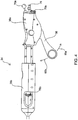
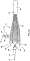
Fig. 5A is a side view of the distal end of the delivery and deployment system of the present invention with an implantable device of the present invention shown partially deployed from the implantation system.Fig. 5B shows a top view of the system and implantable device ofFig. 5A .Fig. 5C shows a longitudinal cross-sectional view ofFig. 5B . -
Fig. 6A is a cross-sectional view taken along line A-A ofFig. 5C .Fig. 6B is a cross-sectional view taken along line B-B ofFig. 5C .Fig. 6C is longitudinal cross-sectional view of the catheter tip portion of the delivery and deployment system ofFig. 5C . -
Figs. 7A, 7B and7C are cross-sectional views of possible embodiments of side branch catheters of the present invention. -
Figs. 8A-8H illustrate various steps of a method of the present invention for delivering a stent of the present invention using an implantation system of the present invention. -
Fig. 9 illustrates another embodiment of handle portion of the delivery and deployment system of the present invention. -
Fig. 10A illustrates a side view of an embodiment of an inner member of the catheter portion of the delivery and deployment system of the present invention.Fig. 10B illustrates a cross-sectional view of the inner member ofFig. 10A taken along the line B-B ofFig. 10A. Fig. 10C illustrates a cross-sectional view of the inner member ofFig. 10 taken along the line C-C ofFig. 10A . -
Fig. 11 illustrates the partial deployment of the implant ofFig. 1E within the aortic root. -
Figs. 12A-12F illustrate various steps of another method of the present invention for delivering a stent of the present invention using an implantation system of the present invention. -
Figs. 13A-13C illustrate various exemplary mandrel designs for fabricating the stents and stent grafts of the present invention. -
Fig. 14 illustrates an exemplary wire winding pattern to form a stent of the present invention. -
Fig. 15 illustrates one manner in grafting a stent of the present invention. - Before the stent delivery and deployment system of the present invention is described, it is to be understood that this invention is not limited to particular therapeutic applications and implant sites described, as such may vary. It is also to be understood that the terminology used herein is for the purpose of describing particular embodiments only, and is not intended to be limiting, since the scope of the present invention will be limited only by the appended claims.
- Unless defined otherwise, all technical and scientific terms used herein have the same meaning as commonly understood by one of ordinary skill in the art to which this invention belongs. The terms "proximal" and "distal" when used to refer to the delivery and deployment systems of the present invention are to be understood to indicate positions or locations relative to the user where proximal refers to a position or location closer to the user and distal refers to a position or location farther away from the user. When used with reference to the implantable devices, these terms are to be understood to indicate positions or locations relative to a delivery and deployment system when the implantable devices is operatively positioned within the system. As such, proximal refers to a position or location closer to the proximal end of the delivery and deployment system and distal refers to a position or location closer to the distal end of the delivery and deployment system. The term "implant" or "implantable device" as used herein includes but is not limited to a device comprising a stent, a graft, a stent-graft or the like.
- It must be noted that as used herein and in the appended claims, the singular forms "a", "an", and "the" include plural referents unless the context clearly dictates otherwise. Thus, for example, reference to "a string" may include a plurality of such strings and reference to "the tubular member" includes reference to one or more tubular members and equivalents thereof known to those skilled in the art, and so forth.
- Where a range of values is provided, it is understood that each intervening value, to the tenth of the unit of the lower limit unless the context clearly dictates otherwise, between the upper and lower limits of that range is also specifically disclosed. Each smaller range between any stated value or intervening value in a stated range and any other stated or intervening value in that stated range is encompassed within the invention. The upper and lower limits of these smaller ranges may independently be included or excluded in the range, and each range where either, neither or both limits are included in the smaller ranges is also encompassed within the invention, subject to any specifically excluded limit in the stated range. Where the stated range includes one or both of the limits, ranges excluding either or both of those included limits are also included in the invention.
- The publications discussed herein are provided solely for their disclosure prior to the filing date of the present application. Nothing herein is to be construed as an admission that the present invention is not entitled to antedate such publication by virtue of prior invention. Further, the dates of publication provided may be different from the actual publication dates which may need to be independently confirmed.The present invention will now be described in greater detail by way of the following description of exemplary embodiments and variations of the system of the present invention. The invention generally includes an implantable device which includes a tubular member in the form of a stent, a graft or a stent graft, where the device may further include one or more branching or transverse tubular members laterally extending from the main or primary tubular member. The invention further includes a system for the percutaneous, endovascular delivery and deployment of the implantable device at a target implant site within the body. The implant site may be any tubular or hollow tissue lumen or organ; however, the most typical implant sites are vascular structures, particularly the aorta. A feature of the invention is that it addresses applications involving two or more intersecting tubular structures and, as such, is particularly suitable in the context of treating vascular trees such as the aortic arch and the infrarenal aorta. Implantable Devices of the Present Invention
- Referring now to the figures and to
Figs. 1A and 1B in particular, there are illustrated exemplary embodiments of implantable devices of the present invention. Each of the devices has a primary or main tubular member and at least one laterally extending tubular branch, however, the implantable devices of the present invention need not have side branches. -
Fig. 1A illustrates one variation of animplantable device 2 having a primary tubular portion, body ormember 4 and laterally extendingside branches main body 4 by way of lateral openings within the body. The proximal and distal ends of the maintubular member 4 terminate in crowns or apexes 8, the number of which may vary. The distal ends of theside branches apexes Device 2 is particularly configured for implantation in the aortic arch whereprimary tubular member 4 is positionable within the arch walls andtubular branches - As will be described in greater detail below, the deployment or attachment members of the subject delivery and deployment systems, are looped through the
apexes device 2. The attachment members of the present invention may be any elongated member including but not limited any strings, filaments, fibers, wires, stranded cables, tubings or other elongated member which are releasably attachable to the distal ends of the various lumens of the stent. Means of releasable attachment include but are not limited to electrolytic erosion, thermal energy, magnetic means, chemical means, mechanical means or any other controllable detachment means. -
Fig. 1B illustrates another variation of adevice 12 having a primary tubular portion ormember 14 and laterally extendingbranches main body 14 by way of lateral openings within the body. The proximal and distal ends of the maintubular member 14 terminate in crowns or apexes 18 which are employed as described above with respect toFig. 1A while the distal ends of theside branches Device 12 is particularly configured for implantation in the infra-renal aorta whereprimary tubular member 14 is positionable within the walls of the aorta andtubular branches - Those skilled in the art will recognize that the subject implants may have any number and configuration of lumens (e.g. a main lumen and one or more side branch lumens) where the one or more side branch lumens may be positioned at any appropriate location along the length of the main lumen and at any angle with respect to the longitudinal axis of the main lumen, and where the there are two or more side branch lumens, the lumens may be spaced axially and circumferentially angled relative to each other to accommodate the target vasculature into which the implant is to be placed. Additionally, the length, diameter and shape (e.g., radius of curvature) of each of the implant's lumens may vary as needed to accommodate the vessel into which it is positioned. Typically, the main branch lumen will have an unconstrained length in the range from about 1 cm to about 25 cm and an unconstrained diameter in the range from about 2 mm to about 42 mm. The side branch lumens will have an unconstrained length in the range from about 0.5 cm to about 6 cm and an unconstrained diameter in the range from about 2 mm to about 12 mm. For example, for aortic applications, the unconstrained length of the main lumen is typically from about 8 cm to about 25 cm and the unconstrained diameter is in the range from about 15 mm to about 42 mm; and the side branch lumens will have an unconstrained length in the range from about 2 cm to about 6 cm and an unconstrained diameter in the range from about 5 mm to about 12 mm. For renal applications, the main branch lumen will have an unconstrained length in the range from about 2 cm to about 5 cm and an unconstrained diameter in the range from about 3 mm to about 9 mm; and the side branch lumens will have an unconstrained length in the range from about 0.5 cm to about 3 cm and an unconstrained diameter in the range from about 2 mm to about 7 mm. For coronary applications, the main branch lumen will have an unconstrained length in the range from about 1 cm to about 3 cm and an unconstrained diameter from about 2.0 mm to about 5 mm; and the side branch lumens) will have an unconstrained length in the range from about 0.5 cm to about 3 cm and an unconstrained diameter in the range from about 2 mm to about 5 mm. For applications in smaller vessels, such as the neurovasculature, these dimensions will of course be smaller. The various structural and functional aspects of the inventive implants are discussed in greater detail below.
- It is also contemplated that therapeutic or diagnostic components or devices may be integrated with the subject implants. Such devices may include but are not limited to prosthetic valves, such as cardiac valves (e.g., an aortic or pulmonary valve) and venous valves, sensors to measure flow, pressure, oxygen concentration, glucose concentration, etc., electrical pacing leads, etc. For example, as illustrated in
Fig. 1E , animplant 210 for treating the aortic root is provide which includes a mechanical or biologicalprosthetic valve 216 employed at a distal end of themain lumen 212.Device 210 further includes two smaller, generally opposingside branch lumens - Those skilled in the art will appreciate that any suitable stent or graft configuration may be provided to treat other applications at other vascular locations at or near the intersection of two or more vessels (e.g., bifurcated, trifurcated, quadrificated, etc.) including, but not limited to, the aorto-illiac junction, the femoral-popiteal junction, the brachycephalic arteries, the posterior spinal arteries, coronary bifurcations, the carotid arteries, the superior and inferior mesenteric arteries, general bowel and stomach arteries, cranial arteries and neurovascular bifurcations.
- As mentioned above, the implantable devices of the present invention may include a stent, referred to as a stent graft, a stented graft or a grafted stent. The stents may be made of any suitable materials known in the art. Preferably, the stent is constructed of wire, although any suitable material may be substituted. The wire stent should be elastically compliant, for example, the stent may be made of stainless steel, elgiloy, tungsten, platinum or nitinol but any other suitable materials may be used instead of or in addition to these commonly used materials.
- The stents may have any suitable wire form pattern or may be cut from a tube or flat sheet. In one embodiment, the entire stent structure is fabricated from a single wire woven into a pattern of interconnected cells forming, for example, a closed chain link configuration. The structure may have a straight cylindrical configuration, a curved tubular configuration, a tapered hollow configuration, have asymmetrical cell sizes, e.g., cell size may vary along the length or about the circumference of the stent. In certain stent embodiments, the cell size of the side branches lumens is gradually reduced in the distal direction. This further facilitates the ability to selectively stretch the distal most portion of the side branch lumens and, thus, making it easier for a physician to guide the distal end of the side branch into a designated vessel. The ends of the main stent lumen and/or the end of one or more side branch stent lumens may be flared. The struts of the stent (i.e., the elemental portions that form a cell) may vary in diameter (in wire embodiments) or thickness or width (in sheet and cut tube embodiments).
- In one particular embodiment, the stent is configured from a single-wire. The single-wire stent configuration is advantageous in that through selective interlacing of the connection points along the length of the stent, it provides for adjustability in the angular orientation of the side branch stents relative to each other and relative to the main stent lumen within a selected range that can accommodate any possible variation in the anatomy being treated. Such angular orientation of the side branch lumens may be axial, circumferential or both.
Fig. 1C illustrates animplant device 20 in whichside branch lumens main lumen 22, and have an angular orientation, defined by angle β, with respect to each other.Fig. 1D is an end view ofimplant device 20 which illustrates the circumferential orientation, defined by angle θ, betweenside branch lumens - The graft portion of a stent graft may be made from a textile, polymer, latex, silicone latex, polyetraflouroethylene, polyethylene, Dacron polyesters, polyurethane or other or suitable material such as biological tissue. Biological tissues that may be used include, but are not limited to, extracellular matrices (ECMs), acellularized uterine wall, decellularized sinus cavity liner or membrane, acellular ureture membrane, umbilical cord tissue and collagen. Extracellular matrices suitable for use with the present invention include mammalian intestinal, stomach, bladder submucosa, dermis or liver basement membranes derived from sheep, bovine, porcine or any suitable mammal. The graft material must be flexible and durable in order to withstand the effects of installation and usage. One of skill in the art would realize that grafts of the subject invention may be formulated by many different well known methods such as for example, by weaving or formed by dipping a substrate in the desired material.
- Submucosal tissues (ECMs) of warm-blooded vertebrates are useful in tissue grafting materials. For example, submucosal tissue graft compositions derived from small intestine have been described in
U.S. Pat. No. 4,902,508 (hereinafter the '508 patent) andU.S. Pat. No. 4,956,178 (hereinafter the '178 patent), and submucosal tissue graft compositions derived from urinary bladder have been described inU.S. Pat. No. 5,554,389 (hereinafter the '389 patent). All of these (ECMs) compositions are generally comprised of the same tissue layers and are prepared by the same method, the difference being that the starting material is small intestine on the one hand and urinary bladder on the other. The procedure detailed in the '508 patent, incorporated by reference in the '389 patent and the procedure detailed in the '178 patent, includes mechanical abrading steps to remove the inner layers of the tissue, including at least the luminal portion of the tunica mucosa of the intestine or bladder, i.e., the lamina epithelialis mucosa (epithelium) and lamina propria, as detailed in the '178 patent. Abrasion, peeling, or scraping the mucosa delaminates the epithelial cells and their associated basement membrane, and most of the lamina propria, at least to the level of a layer of organized dense connective tissue, the stratum compactum. Thus, the tissue graft material (ECMs) previously recognized as soft tissue replacement material is devoid of epithelial basement membrane and consists of the submucosa and stratum compactum. - The (ECMs) epithelial basement membrane may be in the form of a thin sheet of extracellular material contiguous with the basilar aspect of epithelial cells. Sheets of aggregated epithelial cells of similar type form an epithelium. Epithelial cells and their associated epithelial basement membrane are positioned on the luminal portion of the tunica mucosa and constitute the internal surface of tubular and hollow organs and tissues of the body. Epithelial cells and their associated epithelial basement membrane are also positioned on the external surface of the body, i.e., skin. Examples of a typical epithelium having a basement membrane include, but are not limited to the following: the epithelium of the skin, intestine, urinary bladder, esophagus, stomach, cornea, and liver.
- Epithelial cells are positioned on the luminal or superficial side of the epithelial basement membrane, opposite to connective tissues. Connective tissues, the submucosa, for example, are positioned on the abluminal or deep side of the basement membrane. Examples of connective tissues used to form the ECMs that are positioned on the abluminal side of the epithelial basement membrane are the submucosa of the intestine and urinary bladder, and the dermis and subcutaneous tissues of the skin. All of these materials are referred to here as ECMs or extracellular matrix material and can be used to coat all or any part of the stent.
- The stent may be coated with or anchored mechanically to the graft, for example, by physical or mechanical means (e.g., screws, cements, fasteners, such as sutures or staples) or by friction. Further, mechanical attachment means may be employed to effect attachment to the implant site by including in the design of the stent a means for fastening it into the surrounding tissue. For example, the device may include metallic spikes, anchors, hooks, barbs, pins, clamps, or a flange or lip to hold the stent in place.
- The stent may be processed in such a way as to adhere a covering, such as made of an ECM material, to only the wire, and not extend between wire segments or within the stent cells. For instance, one could apply energy in the form of a laser beam, current or heat to the wire stent structure while the ECM has been put in contact with the underlying structure. Just as when crooking meat on a hot pan leaves tissue, the ECM could be applied to the stent in such a manner.
- The subject stents, grafts and/or stent grafts may be coated in order to provide for local delivery of a therapeutic or pharmaceutical to the disease site. Local delivery requires smaller dosages of therapeutic or pharmaceutical delivered to a concentrated area; in contrast to systemic dosages which require multiple administrations and loss of material before reaching the targeted disease site.
- The submucosa tissue may have a thickness of about 80 micrometers, and consists primarily (greater than 98%) of a cellular, eosinophilic staining (H&E stain) extracellular matrix material. Occasional blood vessels and spindle cells consistent with fibrocytes may be scattered randomly throughout the tissue. Typically the UBS is rinsed with saline and optionally stored in a frozen hydrated state until used.
- Fluidized UBS can be prepared in a manner similar to the preparation of fluidized intestinal submucosa, as described in
U.S. Pat. No. 5,275,826 . The UBS is comminuted by tearing, cutting, grinding, shearing and the like. Grinding the UBS in a frozen or freeze-dried state is preferred although good results can be obtained as well by subjecting a suspension of submucosa pieces to treatment in a high speed (high shear) blender and dewatering, if necessary, by centrifuging and decanting excess water. Additionally, the comminuted fluidized tissue can be solubilized by enzymatic digestion of the bladder submucosa with a protease, such as trypsin or pepsin, or other appropriate enzymes for a period of time sufficient to solubilize said tissue and form a substantially homogeneous solution. - The coating for the stent may be powder forms of UBS. In one embodiment a powder form of UBS is prepared by pulverizing urinary bladder submucosa tissue under liquid nitrogen to produce particles ranging in size from 0.1 to 1mm2. The particulate composition is then lyophilized overnight and sterilized to form a solid substantially anhydrous particulate composite. Alternatively, a powder form of UBS can be formed from fluidized UBS by drying the suspensions or solutions of comminuted UBS.
- The subject stents, grafts and/or stent grafts are coated by applying a primer layer onto its surface. The primer layer formulates a reservoir for containing the therapeutic /pharmaceutical. The overlapping region between the primer layer and active ingredient may be modified to increase the permeability of the primer layer to the active ingredient. For example, by applying a common solvent, the active ingredient and the surface layer mix together and the active ingredient gets absorbed into the primer layer. In addition, the primer layer may also be treated to produce an uneven or roughened surface. This rough area entraps the active ingredient and enhances the diffusion rate of the ingredient when the stent is inserted into the patient's body. As such, the implant has the ability to diffuse drugs or other agents at a controllable rate. Furthermore, one of skill in the art would understand that the subject invention may provide a combination of multiple coatings, such as the primer lay may be divided into multiple regions, each containing a different active ingredient.
- The subject stents, grafts and/or stent grafts may be coated with any therapeutic material, composition or drug, including but not limited to, dexamethasone, tocopherol, dexamethasone phosphate, aspirin, heparin, coumadin, urokinase, streptokinase and TPA, or any other suitable thrombolytic substance to prevent thrombosis at the implant site. Further therapeutic and pharmacological agents include but are not limited to tannic acid mimicking dendrimers used as submucosa stabilizing nanomordants to increase resistance to proteolytic degradation as a means to prevent post-implantational aneurysm development in decellularized natural vascular scaffolds, cell adhesion peptides, collagen mimetic peptides, hepatocyte growth factor, proliverative/antimitotic agents, paclitaxel, epidipodophyllotoxins, antibiotics, anthracyclines, mitoxantrone, bleomycins, plicamycin, and mitomycin, enzymes, antiplatelet agents, non-steroidal agents, heteroaryl acetic acids, gold compounds, immunosuppressives, angiogenic agents, nitric oxide donors, antisense oligonucleotides, cell cycle inhibitors, and protease inhibitors.
- The subject implants may also be seeded with cells of any type including stem cells, to promote angiogenesis between the implant and the arterial walls. Methods have included applying a porous coating to the device which allows tissue growth into the interstices of the implant surface. Other efforts at improving host tissue in growth capability and adhesion of the implant to the host tissue have involved including an electrically charged or ionic material in the tissue-contacting surface of the device. As mentioned earlier, the subject stents and grafts may also be provided with a covering or otherwise be implanted or embedded with or be completely fabricated from an extracellular matrix (ECM) material. Suitable ECM materials are derived from mammalian hosts sources and include but are not limited to small intestine submucosa, liver basement membrane, urinary bladder submucosa, stomach submucosa, the dermis, etc. Other examples of ECM material includes but is not limited to fibronectin, fibrin, fibrinogen, collagen, including fibrillar and non-fibrillar collagen, adhesive glycoproteins, proteoglycans, hyaluronan, secreted protein acidic and rich in cysteine (SPARC), thrombospondins, tenacin, and cell adhesion molecules, and matrix metalloproteinase inhibitors.
- The ECM portion of the implant is eventually resorbed by the surrounding tissue, taking on the cellular characteristics of the tissue, e.g., endothelium, smooth muscle, adventicia, into which it has been resorbed. Still yet, an ECM scaffolding having a selected configuration may be operatively attached to a stent or stent graft of the present invention at a selected location whereby the ECM material undergoes subsequent remodeling to native tissue structures at the selected location. For example, the ECM scaffolding may be positioned at the annulus of a previously removed natural aortic valve configured in such a way as to create the structural characteristics of aortic valve leaflets and whereby the implant provides valve function.
- The stent, graft, or stent graft of the present invention may also include a sensor or sensors to monitor pressure, flow, velocity, turbidity, and other physiological parameters as well as the concentration of a chemical species such as for example, glucose levels, pH, sugar, blood oxygen, glucose, moisture, radiation, chemical, ionic, enzymatic, and oxygen. The sensor should be designed to minimize the risk of thrombosis and embolization. Therefore, slowing or stoppage of blood flow at any point within the lumen must be minimized. The sensor may be directly attached to the outer surface or may be included within a packet or secured within the material of the stent, graft, or stent graft of the present invention. The biosensor may further employ a wireless means to deliver information from the implantation site to an instrument external to the body.
- The stent, graft or stent graft may be made of visualization materials or be configured to include marking elements, which provide an indication of the orientation of the device to facilitate proper alignment of the stent at the implant site. Any suitable material capable of imparting radio-opacity may be used, including, but not limited to, barium sulfate, bismuth trioxide, iodine, iodide, titanium oxide, zirconium oxide, metals such as gold, platinum, silver, tantalum, niobium, stainless steel, and combinations thereof. The entire stent or any portion thereof may be made of or marked with a radiopaque material, i.e., the crowns of the stent.
- The stent of the present invention may be fabricated in many ways. One method of making the stent is by use of a mandrel device such as the
mandrel devices Figs. 13A-13C , respectively. Each of the devices has at least amain mandrel component device 340, may be provided with at least oneside mandrel 346 extending substantially transverse to themain mandrel 342, where the number of side mandrels preferably corresponds to the number of stent side branches to be formed. The mandrel devices may be modular where side branch mandrels of varying diameters and lengths can be detachably assembled to the main mandrel. The configuration of the main mandrel as well as the side branch mandrel(s) may have any suitable shape, size, length, diameter, etc. to form the desired stent configuration. Commonly, the mandrel components have a straight cylindrical configuration (seeFigs. 13A and 13C ) having a uniform cross-section, but may be conical with varying diameters along a length dimension (seeFig. 13B ), frustum conical, have an oval cross-section, a curved shape, etc. - The pins may be permanently affixed to the mandrel components or are themselves removable from and selectively positionable within holes formed in the mandrel components. Still yet, the mandrel device may be configured to selectively extend and retract the pins. The number of pins and the distance and spacing between them may be varied to provide a customized pin configuration. This customization enables the fabrication of stents having varying sizes, lengths, cell sizes, etc. using a limited number of mandrel components. For example, in one variation, the pins are arranged about the mandrel components in an alternating pattern such as for example, where four out of eight pin holes per row will be filled with pins. Alternatively, a selection of mandrels may be provided, each having a unique pinhole pattern which in turn defines a unique stent cell pattern.
- To form the stent, a shape memory wire, such as a NTIINOL wire, having a selected length and diameter are provided. Typically, the length of the wire ranges from about 9 to about 12 feet long, but may be longer if needed or shorter if more practical. The wire's diameter is typically in the range from about 0.025 mm (0.001 inch) to about 0.51 mm (0.020 inch). After providing a mandrel device having winding pins at the desired points or locations on the mandrel components, the wire is wound about the pins in a selected direction and in a selected over- and-under lapping pattern, e.g., a zigzag pattern, to form a series of interconnected undulated rings resulting in a desired cell pattern.
- An exemplary
wire winding pattern 350 is illustrated inFig. 14 . Starting from one end of the main mandrel, thewire 352 is wound around thepins 354 in a zigzag pattern back and forth from one end of the main mandrel to the other until the cells of the main lumen of the stent have been formed. Next, the same wire, still attached to the mandrel device, is used to form the side branch lumen(s) where the wire is wrapped in a zigzag fashion from the base of the side branch mandrel to the distally extending end and back again until all of the cells of the side branch have been created. Then the wire is wound about the main mandrel along a path that is at an angle to longitudinal axis of the main mandrel where the wire is doubled over itself alongcertain cell segments 356. It should be noted that any lumen of the stent may be fabricated first, followed by the others, or the winding pattern may be such that portions of the various lumens are formed intermittently. - The mandrel device with the formed wire stent pattern are then heated to a temperature in the range from about 480°C to about 520 °C and typically to about 490°C for approximately 20 minutes, however, this time may be reduced by using a salt bath. The duration of the heat-setting step is dependent upon the time necessary to shift the wire material from a Martensitic to an Austenitic phase. The assembly is then air cooled or placed into a water bath to quench for 30 seconds or more and then allowed to air dry. Once the stent is sufficiently dried, the pins are either pulled from the mandrel device or retracted into the hollow center of the mandrel by an actuation of an inner piece which projects the pins out their respective holes in the outer surface of the mandrel. The stent with its interconnected lumens can then be removed from the mandrel device. Alternatively, with the mandrel components detached from one another, one of the lumens, e.g., the main stent lumen, may be formed first followed by formation of a side branch lumen after attachment of a side mandrel to the main mandrel.
- Optionally, selected regions of the main body or the portions of the wire forming the side branch lumen cells may be selectively reduced in diameter by etching or e-polishing so as to exert less radial force than that wire portion of the stent that has not been reduced in wire diameter. One example of a selective reduction of wire diameter in the main body of the stent is to leave a one to two centimeter circumferential portion on each of the proximal and distal ends to allow high radial force at those regions to secure the stent from migration while the center portion between those high radial force regions can be reduced in cross sectional wire diameter in order to facilitate stretching the stent more easily during placement or allowing it to compact into the delivery sheath more easily over a long length. Another example of selectively reducing the wire cross sectional diameter is to make the struts of the side branch smaller in diameter. This can be done by selective immersion of the side branch in an acid during manufacture to reduce the amount of metal in a particular region of the stent. Another method to accomplish the desired result of preferentially reducing side branch longitudinal stiffness and/or outward radial force of the side branch component is to use an electropolishing apparatus. By placing the woven solid wire stent into an electrolyte bath and applying a voltage potential across an anode-cathode gap, where the stent itself is the anode, metal ions are dissolved into the electrolytic solution. Alternatively, or subsequently, the process may be reversed wherein the stent becomes the cathode and the side branch or other selected region of the stent may be electroplated with a similar or different metal in ionic solution, for instance gold or platinum, in order to either change the mechanical properties or to enhance the radiopacity of the selected region. Those skilled in the art of electroplating and electropolishing will recognize that there are techniques using a "strike" layer of a similar material to the substrate in order to enhance the bonding of a dissimilar material to the substrate. An example would be the use of a pure nickel strike layer on top of a nickel titanium (NITINOL) substrate in order to subsequently bond a gold or platinum coating to the substrate.
- Another method of making the stent is to cut a thin-walled tubular member, such as stainless steel tubing, to remove portions of the tubing in the desired pattern for the stent, leaving relatively untouched the portions of the metallic tubing which are to form the stent. The stent also can be made from other metal alloys such as tantalum, nickel-titanium, cobalt-chromium, titanium, shape memory and superelastic alloys, and the nobel metals such as gold or platinum.
- In accordance with the invention, one of skill in the art would know that several different methods may be employed to make the subject stents such as using different types of lasers; chemical etching; electric discharge machining; laser cutting a flat sheet and rolling it into a cylinder; all of which are well known in the art at this time.
- Where a
stent graft 360 is to be formed by the addition of agraft material 362, such as an ECM, to thesubject stent 364, any manner of attaching the graft material to the wire form may be used. In one variation, the graft material is attached by way of asuture 366. As such, oneedge 370 of the graft material is stitched lengthwise to the stent frame along the stents length, where at least oneknot 368 is tied at each apex of the stent to secure an end of the graft to the stent. Then the graft material is stretch around the surface of the stent and theopposite edge 372 of the graft is overlapped with the already attachededge 370 and independently stitched to the stent frame to provide a leak free surface against which blood cannot escape. The graft material is stretched to an extent to match the compliance of the stent so that it does not drape when the stent is in the expanded state. Upon complete attachment of the graft material to the stent, the graft is dehydrated so that it snuggly shrinks onto the stent frame similar to heat shrink tubing would when heated. - Referring now to
Figs. 2A and2B , there is shown asystem 30 of the present invention for implanting the devices of the present invention.System 30 includes adistal catheter portion 32 and a proximal or handleportion 34.Catheter portion 32 is configured for positioning within the vasculature or other pathway leading to the implant site, and includes various elongated members having a plurality of lumens, many of them multi-functional, for guide wire, pull-wire, and fluid passage from one end of the device to the other.Catheter portion 32 includes a translatableouter sheath 38 having a lumen within which anintermediate member 40 is received. The proximal end ofouter sheath 38 is configured with a fitting 50 for coupling to adistal hub 52 ofintermediate portion 40. Fitting 50 is configured with an internal valve mechanism which fluidly seals the luminal space between the walls ofouter member 38 andintermediate member 40, thereby preventing leakage of blood therefrom. Fitting 50 may further include a flush port (not shown) for evacuation of any residual air as is common in catheter preparation. Aninner member 42 is received and translatable within a lumen 138 (seeFig. 6A ) ofintermediate member 40 and defines a main bodyguide wire lumen 44 for translation of aguide wire 48 therethrough.Inner member 42 terminates at a conicaldistal tip 46 which facilitates forward translation of the device through tortuous vasculature. The outer member, intermediate member and inner member tubings (as well as any catheter components discussed below) may be made from materials used to construct conventional intravascular sheaths and catheters, including but not limited to biocompatible plastics reinforced with braided materials or any other biocompatible materials which are substantially flexible. - The
proximal portion 34 of delivery anddeployment system 30 includes proximal anddistal handle portions Inner member 42 is fixed toproximal portion 36a of the handle andintermediate member 40 is fixed todistal portion 36b of the handle such that axial separation and extension of the two handle portions relative to each other controls the amount of extension and foreshortening undergone by a stent operatively loaded within the delivery system, as will be explained in greater detail below. - As mentioned above, the delivery and deployment of an implant of the present invention is accomplished by the use of a plurality of designated attachment lines, strings, wires or filaments. A single string or a set or plurality of strings is provided for controlling and releasably attaching each free end of the implant to the delivery system. Two separate strings or sets of strings are employed to control the main tubular portion of an implantable device-one string or set of strings for controlling the distal end and the other for controlling the proximal end of the device. For each lateral branch of the implant, an additional string or set of strings is provided. The number of strings in each set correlates to the number of crowns or connecting points provided at the respective ends (i.e., at the proximal and distal ends of the main stent portion and at the distal ends of the branch portions) of the device. Each string is interlooped with a designated crown with both of its ends positioned and controlled at the handle of the device, where one end of each attachment string is permanently affixed to the delivery and
deployment system 30 and the other end is releasably attachable to the delivery anddeployment system 30. When operatively loaded withinsystem 30, the luminal ends of the implant are releasably attached to various portions ofsystem 30. For example, the distal end of the main lumen of the stent is releasably attached toinner member 42, the proximal end of the main lumen of the stent is releasably attached tointermediate member 40, and the distal end of each side branch stent is releasably attached to a designated side branch catheter 150 (seeFig. 6A ). - Each attachment string or set of attachment strings is controlled, i.e., able to be fixed, released, tensioned, pulled; tightened, etc., by a designated control mechanism. Accordingly, the number of control mechanisms provided on the illustrated embodiment of the subject system corresponds to the number of attachment string sets; however, control of the string sets may be consolidated into a fewer number of control mechanisms. The various control mechanisms may have any suitable configuration and be mounted at any suitable location on
system 30 where one exemplary configuration and location of the control mechanisms is illustrated inFig. 2A . In particular, each control mechanism includes a pair of controls in the form of knobs, dials, switches or buttons, for example, where one control is for linearly translating, i.e., pulling, the strings by their fixed ends through thedeployment system 30 when deploying the implant, and the other control is for selectively releasing and fixing the free ends of the strings prior to deployment of the implant. -
Controls handle portions intermediate member 40 where the collective hubs are serially arranged between theproximal end 50 ofouter sheath 38 and the distal end ofdistal handle portion 36b. For example, for use withimplant 2 ofFig. 1A having threebranch lumens hubs controls stent branch lumens 6a, the second or middle pair ofcontrols 76a, 76b controls the attachment strings for the middlestent branch lumen 6b, and the most proximal pair ofcontrols stent branch lumens 6c. - Each pair of controls includes a fixed-
end member Fig. 2B , each knob is positioned within ahemostatic valve 80 for preventing the back flow of fluid, e.g., blood, out of the handle or hub before and after the knob is removed therefrom. Each pair of controls also includes a releasable end member orclamp - Referring now to
Figs. 2B ,3A and3B , each sidebranch control hub branch catheter hub hubs Fig. 2B ). Extending between each pair of hubs is a proximal portion 94a, 94b, 94c ofside branch catheters Fig. 6A ), which extends from asealable port Fig. 2B ) at the back end of eachcontrol hub branch catheter lumens 148 within intermediate member 40 (seeFig. 6A ). Within eachside branch catheter guide wire lumen Fig. 6A ).Port branch guide wire Fig. 6A ) through a respective side branch guide wire lumen 152. One or both of the side branch catheter and side branch guidewire may be deflectable. Each of thecontrol hubs intermediate member 40. The undersides of the control hubs havecuff 96, a partial ring configuration or the like, such that hubs are fully releasable fromintermediate member 40 as well as slidable thereon. As mentioned above, each of the side branch stent lumens is releasably coupled to the distal end ofside branch catheter branch control hubs branch catheter hubs Figs. 3A and3B until they are released by theirrespective control knobs Figs. 2A and3B , where the proximal portion 94a, 94b, 94c ofside branch catheter Figs. 2B and3A , each side branch stent is held in a deployed or unstretched condition. - The
side branch catheters branch catheter hubs hemostatic valve branch control hub - A
main body port 76, as illustrated inFig. 4 , located on the back end ofproximal handle portion 36a is in fluid communication with aguide wire lumen 44 which extends through a central lumen 138 (seeFigs. 6A and6B ) withinintermediate member 40.Guide wire lumen 44 provides for the passage and translation of aprimary guide wire 48 which is used to direct and guidedistal portion 32 of the system to a target implant site within the vasculature as well as to facilitate the positioning and implantation of the distal end of the primary lumen of the implantable device. Themain body port 76 has a leur fitting similar to leur fitting 110 described above with respect to the side branch catheter control hubs. - As is further illustrated in
Fig. 4 , alever mechanism 56 extending distally and downwardly fromproximal handle portion 36a is provided for steeringdistal catheter portion 32 ofdevice 30 through the vasculature into which it is positioned. This lever may be replaced by arotating control knob 193 in anotherhandle embodiment 194 shown in Fig. 9A. A steering pull-wire, string or filament (not shown) is fixed to the proximal end oflever 56 and extends throughcatheter portion 32 where its distal end terminates and is attached withinnose cone 46 ofinner member 42.Lever 56 is pivotally coupled withinhandle portion 36a such that when rotated in a downward direction (indicated byarrow 65a ofFig. 4 ), the steering pull-wire is caused to be in a relaxed or slacken state. Conversely, whenlever 56 is rotated upward (indicated byarrow 65b), the steering pull-wire is pulled or tensioned thereby causing the distal tip ofinner member 42, and thus the distal end ofdevice 30, to bend. Any number of steering pull-wires may be employed and selectively tensioned to selectively articulate the distal end ofdevice 30 in multiple directions orthogonal to the longitudinal axis of the implantation system. Typically, the subject delivery and deployment system will have at least one, and often two to four distal points of articulation. These articulation points may be at one or more distances from the distal end of thecatheter 32 in order to create compound curves of the distal end of the catheter. - The relative positioning and interfacing of the implantable device with the various catheters, lumens, guidewires, ports and pull-wires of the subject implantation system will now be described with respect to
Figs. 5A-6C, 6A and 6B .Figs. 5A-5C illustrate animplantable device 120 partially deployed from thedistal end 118 ofouter sheath 38.Implantable device 120 includes a maintubular body 122 and may include one or more lateraltubular branches 124. At the distal tips of crowns or apexes 126 ofmain body 122 and crowns or apexes 128 ofside branch 124 may be eyeletloops 130 for receiving attachment strings 132 (shown only inFig. 5C ). Any means of looping the attachment wires to the end ofside branch 124 may be used including passing attachment strings or strings through the windows provided by the cell structure terminating at an apex. As is illustrated inFig. 5C , when operatively loaded withinsystem 30 ofFig. 2A , themain lumen 122 ofdevice 120 is longitudinally disposed betweenouter sheath 38 andinner member 42 and is positioned distally of thedistal end 134 ofintermediate member 40. - To load the implant device into
outer sheath 38, the handle controls are set to stretch the stent by extension of thedistal tip 46 of theinner member 42 relative to the distal end of the intermediate member. When proximal anddistal handle portions Fig. 8D , the main lumen of the stent is in a stretched or tensioned condition. Conversely, when proximal anddistal handle portions Fig. 8E , the main lumen of the stent is in an unstretched or untensioned condition. The distal lumenal ends ofinner member 42 andintermediate member 40 are connection points for the string or strings which are releasably attached to the distal and proximal stentmain lumen openings 122. As discussed above, the side branch stent distal lumenal end is releasably attached to the distal end of the side branch catheter. -
Fig. 6A shows a cross-section of a distal portion of implantation system along the lines A-A ofFig. 5C , specifically, the cross-sectional view is taken at the distal end ofintermediate member 40. This view shows the nested relationship betweenouter member 38,intermediate member 40,inner member 42 which is positioned withincentral lumen 138 ofintermediate member 40, andmain guide wire 48 positioned within a centralguide wire lumen 44 ofinner member 40 which extends distally throughtip 46. -
Inner member 42 is a very small diameter catheter, for example, in the range of 3 to 8 French for cardiovascular applications, and has, in addition to centralguide wire lumen 44, a plurality ofattachment string lumens 140 circumferentially disposed about centralguide wire lumen 44 which serve to direct the alignment of the attachment strings to the connection points on the distal end of the main stent lumen.Multiple lumens 140 are located at the distal portion ofmember 42 and extend along the entire length of theinner member 42.Lumens 140 may be in communication with one or more flush ports at the handle portion of the delivery system whereby saline may be flushed throughlumens 140 at a pressure greater than that of the surrounding blood flow to prevent blood flow through the device lumens.Lumens 140 may also be used to deliver radiopaque contrast dye used during fluoroscopically visualized placement of the device.Lumens 140 and theexit ports 186, described below, allow for visualization of the dye flowing through the implant at various stages of deployment in order to verify that placement of the stent yields a satisfactory flow pattern and therapeutic result. - In other embodiments, such as that illustrated in
Figs. 10A, 10B and 10C ,attachment string lumens 140 may extend along only a portion of the length ofinner member 40, e.g., only a few millimeters distally to proximally. This embodiment is particularly suitable in the case where only one attachment string is employed with multiple stent connection points. Here, the single string element exits one of the distal lumens, is passed through the stent connection point, is passed distally to proximally through another of the lumens, exits proximally from that lumen and is passed through another of the lumens distally to proximally and passed through another stent connection point. The interlacing pattern continues until all stent connection points are laced with the singular string which passes through the multiple circumferential lumens. This configuration of attachment string lumens which extend only a portion of the length of the inner member, may also be employed with theintermediate member 40 and with the side branch catheters 94a, 94b, 94c. With respect to an intermediate member employing such a string lumen configuration, the proximal portion ofintermediate member 40 would be a single lumen containing theinner member 42 and the shorter circumferential lumens would contain the side branch catheters as well as the attachment wires for the proximal end of the main stent lumen. As will be seen from this embodiment and those discussed below, any combination of lacing patterns may be used to attach an individual stent end to the respective catheter to which it is attached. - Referring again to the embodiment
Fig. 6A , the number of distalattachment strings lumens 140 is double the number of attachment strings 132 where one pair of adjacentattachment strings lumens distal attachment string 132. As such, wheredevice 120 is fully loaded within the deployment system, the first portion of adistal attachment string 132 resides withinlumen 140a and a second or return portion of the distal attachment string resides withinlumen 140b. - In addition to
attachment string lumens 140 are one or more steering pull-wire lumens 142, the function of which is as described above with respect toFig. 4 . Typically, one or two pairs of diametrically opposed (180° apart) steering pull-wires are employed to provide opposing orthogonal deflections of the distal end of the delivery system. The greater the number of steering pull-wire pairs employed, the greater the directions of steering in articulating the delivery system. - In addition to
central lumen 138 through whichinner member 42 is translated,intermediate member 40 includes a plurality of proximal attachmentstring lumen pairs lumen 146a is shown situated radially outward fromlumen 146b. The attachment strings attached to or threaded through the proximal crowns (not shown) ofmain lumen 122 ofdevice 120 utilize lumens 146. The number of proximal attachment string lumens 146 is double the number of proximal attachment strings where one pair ofattachment string lumens device 120 is fully loaded within the delivery and deployment system, the fixed-end portion of a proximal attachment string resides withinlumen 146a and the distal or return portion of the proximal attachment string resides withinlumen 146b. - In addition to attachment string lumens 146,
intermediate member 40 also provides a plurality oflumens 148, also circumferentially disposed aboutcentral lumen 138 and preferably interposed between pairs of proximal attachment lumens 146, where one or more of thelumens 148 may be employed to translate and deliver a side branch catheter 150 (shown inFig. 6A without detail).Side branch catheter 150 provides a central side branch guide wire lumen 152 for delivering and translating a sidebranch guide wire 154.Additional lumens 148 extending from a handle flush port (not shown) may be provided for evacuating air from thedelivery system 30. Theadditional lumens 148 may also allow for the rehydration of tissue graft coverings or other coverings which need to be prepared with solutions and potential therapeutic agents such as pharmacologics, stem cells, or other agents. This allows the stent graft or other device to be constrained in the delivery catheter in a dried dehydrated state subsequently packaged, sterilized, and rehydrated by the flushing and preparing the catheter at the time of use. Anyunused lumens 148 provide enhanced flexibility of the intermediate member, particularly where the distal end of the device is deflectable at multiple articulation points. -
Figs. 7A, 7B and7C illustrate various possible embodiments of side branch catheters suitable for use with the delivery system of the present invention.Side branch catheter 160 ofFig. 7A provides a centralguide wire lumen 162 and plurality ofattachment string lumens 164 arranged circumferentially aboutcentral lumen 162.Lumens 164 are utilized or occupied by the attachment strings (not shown) which are looped or threaded through thedistal crowns 128 ofside branch lumen 124 of device 120 (seeFig. 5A ). The number of side branchattachment string lumens 164 is double the number of side branch attachment strings where one pair ofattachment string lumens device 120 is fully loaded within the implantation system, the proximal portion of a side branch attachment string resides withinlumen 164a and the distal or return portion of the side branch attachment string resides withinlumen 164b. -
Side branch catheter 170 ofFig. 7B provides anouter member 172 having acentral lumen 174 and aninner member 176 positioned concentrically therein.Inner member 176 also has acentral lumen 178 for translating and delivering a side branch guide wire (not shown).Outer member 172 further provides a plurality of side branchattachment string lumens 180 where there is a one-to-one correspondence between the number of side branchattachment string lumens 180 and the number of side branch attachment strings (not shown). In this embodiment, the proximal portion of side branch attachment strings reside within the space between the internal diameter ofouter member 172 and the external diameter ofinner member 176 and after being looped through the distal attachment eyelets, crowns or cells, the distal or return portion of the strings pass throughlumens 180 ofouter member 172. - In another embodiment of
side branch catheter 200, shown inFig. 7C the side branch catheter can be composed of two concentric single lumens. Onesingle lumen tubing 202 defining an internal diameter and anothersingle lumen tubing 203 defining an outer diameter provides for the side branch attachment strings to be contained within thespace 201 between the internal diameter of theouter tubing 202 and the outer diameter of theinner tubing 203. The internal diameter of the inner tubing is used to translate a guidewire (not shown) through sidebranch guidewire lumen 204 which is isolated from the attachment strings as shown inFig. 7C . This lumen configuration may also be employed with the intermediate and inner members. - Referring to
Fig. 6B , there is shown a cross-sectional view taken along lines B-B ofFig. 5C , specifically through a proximal end ofdistal tip 46 whereinner member 42 terminates.Distal tip 46 provides the distal portion ofguide wire lumen 44 as well as thedistal lumen portions 182 of distalattachment string lumens 140 ofinner member 42 where the plurality ofdistal lumen portions 182 are axially aligned and have a one-to-one correspondence with inner memberattachment string lumens 140. As such, the same pairing of adjacentattachment string lumens distal attachment string 132, i.e., where the fixed-end portion of adistal attachment string 132 resides withinlumen portion 182a and the releasable or return portion of the distal attachment string resides withinlumen portion 182b. As is best illustrated inFig. 6C , after passing withinlumen portions 182a, the attachment strings 132 are passed radially out ofdistal tip 46 through designatedproximal side ports 184. The attachment strings are then looped or threaded aroundeyelets 130 or crowns orapices 126 or through the very distal cells ofmain lumen 122, and threaded back through the designatedside port 184 ofdistal tip 46 whereby they re-enterrespective lumen portions 182 and respectiveattachment string lumens 140. As such, for every pair of attachment string lumens, there are half asmany side ports 184, i.e., there is a one-to-one correspondence between the number of attachment strings 132 and the number of distaltip side ports 184.Distal tip 46 also provides fordistal side ports 186 to facilitate the loading of strings during assembly of the implant to the deliver system. - The catheters and/or guidewires employed with the systems of the present invention may include intravascular ultrasound (IVUS) imaging capabilities where one or more miniaturized transducers are mounted on the tip of a catheter or guidewire to provide electronic signals to an external imaging system. Such a transducer array may rotate to produce an image of the lumen of the artery showing the precise location of the take offs for the connected branch vessels that will receive the connected branch stents or other cavities into which the catheter is inserted, the tissue of the vessel, and/or the tissue surrounding the vessel. In addition to facilitating visualization during stent delivery and deployment, such systems enhance the effectiveness of diagnosis and treatment by providing important diagnostic (i.e., pre-stenting) information, e.g., the location and size of an aneurysm, that is not available from conventional x-ray angiography. Intravascular ultrasound (IVUS) imaging catheters are commonly used as a preliminary step in the procedure of selecting the appropriately sized stent graft before placing a non-branched stent for several reasons which include to ensure that coverage of a side branch vessel is not mistakenly done. Combining the imaging ability into the tip of the stent delivery catheter has the advantages of saving time by avoiding a catheter exchange. A second technique which is commonly done to avoid the exchanging of the stent delivery catheter and the IVUS catheter through the access site is to gain another access point to introduce the separate IVUS catheter. By integrating the IVUS transducers on the tip of the stent delivery catheter, one eliminates the need for a second vascular access wound should the imaging catheter have been delivered through a bilateral groin access location. Also, when placing a stent inside another stent, an IVUS catheter is used to ensure that the second stent will be deployed within the lumen of the first stent in an overlapping fashion to extend the coverage length of the treated region. In those cases, a first stent has been placed and the downstream portion is free floating within a large aneurysm sac and, as such, care must be taken to ensure that the second stent to be placed within the first stent is not outside the lumen of the first stent. To do otherwise, may result in unintentionally occluding the vessel requiring the procedure to be converted to a surgery to remove the misplaced second stent.
- The implantation procedure for the subject devices will now be described with respect to
Figs. 8A-8H and in the context of an aortic arch application in which a stent-graft 2 of the present invention, such as that illustrated inFig. 1A , having amain body lumen 4 and threeside branch lumens aortic arch 5, where, upon implantation,main body lumen 4 will reside within theaortic arch 5 and the threeside branch lumens innominate artery 7a, the left commoncarotid artery 7b and the leftsubclavian artery 7c, respectively, as illustrated inFig. 8H . - By means of a Seldinger technique via the left
femoral artery 8, or abdominal aortatomy, a main oraortic guide wire 48 is advanced through the vasculature to theaortic arch 5 up to or untildistal tip 48a is caused to cross theaortic valve 10, as illustrated inFig. 8A .Catheter portion 32 of theimplantation system 30 of the present invention, provided with stent-graft 2 operatively loaded therein, is then percutaneously introduced into the patient's body overguide wire 48. - It is noted that stent-grafts or stents otherwise covered with a material, e.g., an ECM, may require reconstitution or hydration of the graft or covering prior to commencing the implantation procedure. This may be accomplished by flushing the guide wire lumen of delivery system catheter with saline prior to inserting the catheter into the body. Alternatively this could be done by rinsing in open air prior to sheathing.
- While
stent graft 2 is in a loaded, undeployed state withincatheter portion 32, the delivery system's handle is in the retracted position, i.e., proximal handle portion 34a and distal handle portion 34b are engaged with each other. With the handle in the retracted position (shown inFigs. 8B and8D ),inner member 42 is held in a distally advanced position andintermediate member 40 is held in a proximally retracted position. This relative axial relationship between the intermediate and inner members, maintainsstent graft 2, or at least itsmain lumen 4, in a stretched or tensioned condition. This is so as the distal crowns ofmain lumen 4 are attached to the distal end ofinner member 42, which in turn is fixed to proximal handle portion 34a, and the proximal crowns ofmain lumen 4 are attached to the distal end ofintermediate member 40, which in turn is fixed to thedistal handle portion 36b. -
Catheter portion 32 is then steered as necessary by means of manipulatinglever 56, thereby deflecting the distal tip ofcatheter 32, as described above with respect toFig. 4 , and advanced into the descending aorta and then intoaortic arch 5. It is important that catheter portion be properly rotationally positioned so thatside branch lumens stent graft 2 are substantially aligned witharteries end catheter 32 is torquable and fluoroscopic guidance may be employed to further facilitate delivery ofcatheter portion 32. In particular, fluoroscopic markers (not shown) on the crowns of the stent graft lumens may be tracked and accurately positioned for optimal placement within the respective arteries. The stent itself may be radiopaque. The tip of the catheter will be radiopaque as well. A steerable guidewire may be used to direct themain catheter 32 and the side branch catheters as the stretched main stent body and side branch stent bodies are steered by deflectable tipped guidewires placed into the target implant site. - Throughout the delivery and deployment procedure, the various lumens of
catheter portion 32 may be continuously flushed with a fluid, e.g., saline or contrast agent, in a retrograde direction (relative to the blood flow) at a pressure that is greater than or substantially equal to the pressure of the arterial blood. This prevents possible leakage of blood from the system as well as prevents any interference with the functioning of the delivery process, particularly keeping the stent strings lumens free and clear of blood, thereby eliminating clotting within the lumens. Additionally, because each lumenal end of the stent graft (i.e., the proximal and distal ends ofmain lumen 4 as well as the distal ends of the side branch lumens) is individually controlled (however, some or all may be collectively controlled) by the delivery anddeployment system 30 of the present invention, the interconnected cells of the stent may be selectively elongated in an axially direction, permitting the continual flow of blood around the device during deployment within the anatomy. This axial elongation feature also permits the implantation of larger diameter side branch stents within a vessel having a smaller diameter. - Once the distal end of
catheter portion 32 is operatively positioned within theaortic arch 5,outer sheath 38 is retracted by manually pulling on fitting 50 (seeFig. 3A ) to expose the proximal end ofnose cone 46 ofinner member 42 and to partially deploy the distal portion of the main oraortic lumen 4 ofstent graft 2 within the ascending aorta, as shown inFig. 8C . With partial deployment ofstent graft 2, i.e., mainaortic lumen 4 is maintained in a stretched or tensioned state, arterial blood flow exiting fromaortic valve 10 flows through and aroundmain lumen 4. It is important to note that withmain lumen 4 in this partially deployed state,stent graft 2 can be easily repositioned within the vasculature as it is not yet engaged with the vessel walls and, thus, is not subject to the frictional resistance that contact with the walls would cause, not to mention the avoidance of the resulting endothelial damage and/or plaque embolization which is likely to occur. - While the various
side branch lumens stent graft 4 may be deployed serially (one at a time) in any order or parallely (simultaneously) together, it may be easiest to deploy the side branch stent lumens one at a time in order from the most distally positioned stent lumen (6a) to the most proximally positioned stent lumen (6a). This deployment order eliminates unnecessary or repetitious translation ofouter sheath 38 over the stent graft, i.e., only gradual, unidirectional (proximal) translation is necessary. This is advantageous in that abrasions to the graft material are minimized, which is particularly important when coated with a material, e.g., extra cellular matrix, or a drug. This deployment order further reduces the necessary deployment steps and, thus, the total time necessary for the implantation procedure. - To deploy a side branch stent lumen, such as
stent lumen 6a, a sidebranch guide wire 154 is inserted into (or may be preloaded within) side branch port 110 of the respective control hub in its full distally advanced position and into a lumen 152 ofside branch catheter 150 positioned withinlumen 148 of intermediate member 40 (seeFig. 6A ). At the same time,outer sheath 38 is incrementally and gradually retracted proximally to allow the distal end ofguide wire 154 to be translated throughside branch catheter 150, out its distal end and intoinnominate artery 7a, as shown inFig. 8C . Therespective control hub 74 is then distally translated alongintermediate member 40 and may be fully engaged with the associatedcatheter hub 84, thereby exerting maximum tension being applied to the side branch stent cells by the attached attachment strings and partially deployingside branch stent 6a as shown in 8D. Note that the main body stent cells are being held stretched distal to proximal through the relative positions of the inner member and intermediate member as controlled by the handle in the close configuration while the side branch stent is likewise maintained in a stretched position by the distally advanced side branch catheter. This procedure is repeated as necessary for the remaining number of side branch stents, in this case,side branch stents carotid artery 7b and the leftsubclavian artery 7c, respectively, as illustrated inFig. 8D . Note that at this partially deployed state the blood flow is around the device as well as through the implant depending on how tight and over what extension length the attachment strings are pulled to the innermember exit ports 184. It may be desirable to have just flow around the device and not through the lumen of the device and that can be accomplished by cinching down on the attachment strings on the distal end of main lumen to allow the most minimal length of attachment thereby bringing the main lumen of stentgraft to be held closed againstdistal tip 46 orinner member 42. It is important to note that the distance between the distal main stent end and its connection to the inner member is controllable by the length of distal attachment strings which are controlled by thestring clamp 70b by adjusting and selecting the location of where the clamp locks onto the distal attachment strings. This adjustment can be made in situ while the stent is being delivered. Likewise the distance between the proximal main stent end and its connection to the intermediate member is controllable by the length of proximal attachment strings which are controlled by thestring clamp 72b by adjusting and selecting the location of where the clamp locks onto the proximal attachment strings. This adjustment can be made in situ while the stent is being delivered. - After placement within the branch arteries of all of the side branch stents in their partially deployed states, the stent graft is ready for full deployment. This is accomplished by moving the system handle to the extended position, i.e., proximal handle portion 34a and distal handle portion 34b are axially separated from each other, as illustrated in
Fig. 8E . This action causesinner member 42 to translate proximally relative to the fixedintermediate member 40 and in turn relaxes the tension applied to the cells ofmain lumen 4, thereby bringing the lumen ends closer together. As such, the stent foreshortens and there is a corresponding increase in the diameter ofmain lumen 4, thereby securingmain lumen 4 against the walls of the aorta. - The side branch catheters are likewise translated proximally by moving the
respective control hub corresponding catheter hub side branch lumens end knob releasable end clamp - Once the stent cells have been released of their tension by the translation of the catheter handle and side branch catheters, and as the stent opens to a diameter which is expanded against the surrounding artery wall, the entire blood flow enters through the distal end of the device and exits all of its other lumens. Preferably, blood flow is sealed from around the outside of the stentgraft once the stent has been fully deployed.
- While the stent itself may be fully deployed as shown in
Fig. 8E , it is still attached by attachment string sets to each of the distal ends ofinner member 42,intermediate member 40 and eachside branch catheter Fig. 8F , the lumenal ends of theside branch lumens side branch catheters branch guide wires 154 having been retracted. For each side branch lumenal end, such as illustrated forside branch lumen 6a, catheter detachment is accomplished by actuating the designatedcontrol clamp respective catheter hub strings 190 from the screw clamp of catheter hub and, at the same time, by removingcontrol knob strings 190 to the extent that the free ends unloop or detach from the respective stent'scrowns 128 ofFig. 8F . Thestrings 190 need only be pulled until their free ends release the crowns but may be withdrawn within the distal end ofcatheter portion 32. - As illustrated in
Fig. 8G , a similar procedure is performed with respect to deployment of the distal and proximal ends ofmain lumen 4, where either end may be deployed first or both ends may be deployed simultaneously The designatedcontrol clamp strings 192 and, at the same time,control knobs strings 192 to the extent that the free ends unloop or detach from the respective stent's crowns 126.Strings 192 need only be pulled until their free ends release the crowns but may be withdrawn within the distal end ofcatheter portion 32. The entirety ofcatheter portion 32 may then be removed from the vasculature withstent graft 2 in a fully deployed state within theaortic arch 5, as shown inFig. 8H . - Referring now to
Fig. 11 , the partial deployment step of the above described procedure is illustrated with respect to the delivery and deployment of theimplant 210 ofFig. 1E . Specifically,catheter portion 38 of the delivery system is positioned within the aorta with the distal portion ofmain stent lumen 122 partially deployed within the aortic root and ascendingaorta 240, andside branch lumens coronary ostia main guidewire 218 extends fromcatheter 38 and crosses the former location of the naturalaortic valve 224, whileside branch guidewires coronary ostia side branch catheters aortic valve 216 will reside within thenatural annulus 224. Theside branch lumens main lumen 212, or serially in any order. - In any surgical or endovascular procedure, such as the one just described, the fewer incisions made within the patient, the better. Of course, this often requires highly specialized instrumentation and tools used by a highly skilled surgeon or physician. In consideration of this, the above-described single-incision device implantation procedure may be modified to include the creation and use of one or more secondary incisions to facilitate the initial delivery of the
catheter portion 38 of thedelivery system 32 at the implantation site and to further ensure proper orientation of the stent graft upon its deployment at the site. - The two-incision (or multiple-incision) procedure of the present invention involves a primary incision, e.g., a cut-down in the femoral artery as described above, through which the above-described delivery and deployment system is introduced into a first vessel within the body, e.g., into the aortic arch, and a second incision (or more) at a location(s) that provides access to at least one vessel which intersects the first vessel, e.g., one of the side branches of the aortic arch. This procedure is now described with reference to
Figs. 12A-12F and in the context of implanting thestent graft 2 of the present invention in the aortic arch by use of a primary incision made in the leftfemoral artery 8 to access theaortic arch 5 and a single secondary incision made in the brachialcephalic orradial artery 15 to access one or more arteries of the aortic tree. - First and second access incisions are made --- in the left
femoral artery 8 and the leftbrachycephalic artery 15, respectively. By means of a Seldinger technique, a secondary or "tether"guide wire 300 is advanced through the leftbrachycephalic artery 15 into the innominate artery 7.Guide wire 300 is then further advanced into theaortic arch 5, the descendingaorta 11, theabdominal aorta 13 and the leftfemoral artery 8 where it exits the body through the femoral incision, as illustrated inFig. 12A . A secondary or "tether"catheter 302 is then tracked over thefemoral end 300a ofguide wire 300 and along the length of the guide wire untilcatheter 302 is advanced out of the brachial incision, as illustrated inFig. 12B . Any suitable off-the-shelf system for cardiovascular applications may be employed for use as the secondary or tether guide wire and catheter. A dual lumen rapid-exchange (RX) catheter, such as the one illustrated, having a second lumen positioned at the proximal end ofcatheter 302. An advantage of an RX catheter is that it only requires the string(s) (or a guidewire) to be pushed a relatively short distance (requiring little "pushability") before it exits the lumen rather than a greater distance in which the string would be difficult to push due to its limp nature. Alternatively, the very end ofcatheter 302 may be provided with a thru-hole or a cross-hole in the catheter wall, as illustrated inFig. 12C' . - The above descried
implantation system 30 is then provided with stent-graft 2 operatively loaded therein. For this procedure, as illustrated inFig. 12C , side branch attachment strings 190, or at least one string thereof, for deploying the most distally located sidebranch stent lumen 6a (i.e., the one intended for implantation into theinnominate artery 7a) and attached thereto (to one or more stent crowns) are extended fromside branch catheter 150a of primary or stentdelivery system catheter 38 and then threaded through a sidebranch tether tubing 35. The strings are then knotted 37a to prevent proximal withdrawal back intocatheter 150a andtubing 35. The remaining distal length ofstrings 190 are then threaded through theexchange lumen 304 oftether catheter 302. The ends of the strings are then knotted asecond time 37b to prevent proximal withdrawal of the strings fromexchange lumen 304. With the secondary catheter embodiment ofFig. 12C' , the strings are threaded into themain lumen 302 and out theside hole 305. The distal string ends are then knotted 37b. -
Secondary catheter 302, withside branch catheter 150a in tow as well as the entirety ofstent catheter 38 including primary ormain guide wire 48, is then advanced back through the femoral incision oversecondary guide wire 300 untilcatheter 302 is fully withdrawn from the brachial incision, as illustrated inFig. 12D , and until the distal end ofside branch catheter 150a is also extended from the brachial incision.Tether guide wire 300 can now be removed from the body. At this point,strings 190 are cut at alocation 307 between the distal end ofside branch catheter 150a and the opposing end ofsecondary catheter 302 to release thetether catheter 302 from the stent deployment system. - By the tension applied to
strings 190 and the translation thereof,side branch 6a ofstent graft 4 has been drawn into theinnominate artery 7a, as illustrated inFig. 12E , in a partially deployed state (i.e., exposed but stretched). Concurrently,stent guide wire 48 is advanced over theaortic arch 5 and across theaortic valve 10, thereby advancingnose cone 46 and thus the distal end of the partially deployed (i.e., exposed but stretched or tensioned)main stent lumen 4 into the ascending aorta. Meanwhile,stent catheter 38 has been tracked overstent guide wire 48 into theaortic arch 5. Continued forward advancement ofstent catheter 38 is blocked by the partially deployedside branch lumen 6a. As discussed above, withmain lumen 4 maintained in a stretched or tensioned state (as well asside branch lumen 6a), various advantages are provided: arterial blood flow exiting fromaortic valve 10 is allowed to flow to the brain and body; repositioning of thestent graft 2 is possible, and the likelihood of endothelial damage and/or plaque embolization from the aortic wall is greatly minimized. - For stents and stent grafts having two or more
side branch lumens Fig. 12F , the procedure described above and illustrated inFigs. 12A-12E with respect to the implantation of a stent having a single side branch lumen is simultaneously performed, with separate designated tether guide wires andcatheters Fig. 12F , with at least the distal end of themain stent lumen 4 accurately positioned and partially deployed within the ascending aorta, the respectiveside branch lumens innominate artery 7a, left commoncarotid artery 7b and the leftsubclavian artery 7c, respectively. Alternatively, one or more of the side branch lumens may be partially deployed as described with respect toFigs. 12A-12F , and the remaining side branch lumens, if any, may be deployed in the manner described above with respect toFigs. 8C and8D . Finally, with allside branch lumens Figs. 8E-8H may be performed to fully deploy the all lumens of the stent graft and remove the delivery system from the body. - While the implants of the present invention have been described as being deployable by elongated members, i.e., strings, it is understood that the subject implants may be configured such that their lumenal ends are configured for deployment by an expandable member or members. For example, each of the ends of the implant (i.e., of the main lumen and of the side branch lumen(s)), in a loaded, undeployed state, may be coupled to one or more of the nested catheters by placement about an expandable balloon affixed to the catheter(s). The balloons, in either a partially or fully expanded state, provide a sufficiently snug fit with the implant ends such that the lumens of the implant may be selectively stretched or tensioned along their lengths when manipulating the catheter components.
- The preceding merely illustrates the principles of the invention. It will be appreciated that those skilled in the art will be able to devise various arrangements which, although not explicitly described or shown herein, are within the scope of the appended claims.
Claims (9)
- A system for delivering and deploying a stent having a distal end and a proximal end and a structure therebetween, wherein the structure has an initial profile which is reducible along a length of the structure and wherein the structure comprises a main lumen and at least one side branch lumen extending laterally from the main lumen and having a distal end, the system comprising:a main catheter having a lumen having a diameter less than a diameter of the stent (2, 12, 20, 210) in the initial profile, the main catheter lumen adapted for receiving the stent in a reduced profile;at least one first string associated with the main catheter and adapted for releasable attachment to the stent;a mechanism for selectively tensioning the at least one first string to selectively increase and selectively reduce the profile of the stent such that the stent can be partially deployed from the main catheter lumen and held in a partially deployed state with tension being applied to the distal end of the stent;a side branch catheter having a proximal end slidably extending through a side branch catheter hub on the main catheter, and a distal end extending within the stent; andat least one second string adapted for releasable attachment of the distal end of the at least one side branch lumen (24, 26, 214) to the distal end of the side branch catheter, the side branch catheter being capable of deflection from the main catheter to position the at least one side branch lumen;a mechanism for selectively tensioning the at least one second string to selectively tension the at least one side branch lumen; andwherein the main lumen and side branch lumen can each be independently stretched.
- The system of claim 1, wherein the tensioning mechanism selectively tensions the at least one first string by pushing the string.
- The system of claim 1, wherein the tensioning mechanism selectively tensions the at least one first string by pulling the string.
- The system of claim 1, wherein the tensioning mechanism is associated with a handle positioned at a proximal end of the main catheter.
- The system of claim 4, wherein the handle comprises means for articulating a distal end of the main catheter in at least on direction.
- The system of claim 4, wherein the tensioning mechanism comprises a rotatable dial on the handle.
- The system of claim 1, wherein the main catheter comprises a plurality of lumens, wherein at least the first or second string is translatable through at least one lumen.
- The system of claim 1, wherein the main catheter comprises a lumen for selectively flushing the catheter with fluid.
- The system of claim 1, wherein said at least one first string comprises a pair of first strings, one of said pair of first strings being adapted for releasable attachment to the distal end of the stent and the other of said pair of first strings being adapted for releasable attachment to the proximal end of the stent.
Priority Applications (1)
| Application Number | Priority Date | Filing Date | Title |
|---|---|---|---|
| EP12169621A EP2543347A1 (en) | 2005-01-10 | 2006-01-09 | Apparatus and method for deploying an implantable device within the body |
Applications Claiming Priority (5)
| Application Number | Priority Date | Filing Date | Title |
|---|---|---|---|
| US11/033,479 US20060155366A1 (en) | 2005-01-10 | 2005-01-10 | Apparatus and method for deploying an implantable device within the body |
| US11/241,242 US8287583B2 (en) | 2005-01-10 | 2005-09-30 | Apparatus and method for deploying an implantable device within the body |
| US75212805P | 2005-12-19 | 2005-12-19 | |
| US75644506P | 2006-01-04 | 2006-01-04 | |
| PCT/US2006/000760 WO2006076328A1 (en) | 2005-01-10 | 2006-01-09 | Apparatus and method for deploying an implantable device within the body |
Related Child Applications (1)
| Application Number | Title | Priority Date | Filing Date |
|---|---|---|---|
| EP12169621A Division-Into EP2543347A1 (en) | 2005-01-10 | 2006-01-09 | Apparatus and method for deploying an implantable device within the body |
Publications (3)
| Publication Number | Publication Date |
|---|---|
| EP1845895A1 EP1845895A1 (en) | 2007-10-24 |
| EP1845895A4 EP1845895A4 (en) | 2010-02-10 |
| EP1845895B1 true EP1845895B1 (en) | 2017-03-22 |
Family
ID=39668859
Family Applications (6)
| Application Number | Title | Priority Date | Filing Date |
|---|---|---|---|
| EP06717905.1A Not-in-force EP1845895B1 (en) | 2005-01-10 | 2006-01-09 | Apparatus for deploying an implantable device within the body |
| EP06717901.0A Not-in-force EP1850790B1 (en) | 2005-01-10 | 2006-01-09 | Apparatus for deploying an implantable device within the body |
| EP12166652A Withdrawn EP2522313A1 (en) | 2005-01-10 | 2006-01-09 | Vascular implants and methods of fabricating the same |
| EP12169621A Withdrawn EP2543347A1 (en) | 2005-01-10 | 2006-01-09 | Apparatus and method for deploying an implantable device within the body |
| EP12166657A Withdrawn EP2522314A1 (en) | 2005-01-10 | 2006-01-09 | Apparatus and method for deploying an implantable device within the body |
| EP06717902A Withdrawn EP1835865A4 (en) | 2005-01-10 | 2006-01-09 | Vascular implants and methods of fabricating the same |
Family Applications After (5)
| Application Number | Title | Priority Date | Filing Date |
|---|---|---|---|
| EP06717901.0A Not-in-force EP1850790B1 (en) | 2005-01-10 | 2006-01-09 | Apparatus for deploying an implantable device within the body |
| EP12166652A Withdrawn EP2522313A1 (en) | 2005-01-10 | 2006-01-09 | Vascular implants and methods of fabricating the same |
| EP12169621A Withdrawn EP2543347A1 (en) | 2005-01-10 | 2006-01-09 | Apparatus and method for deploying an implantable device within the body |
| EP12166657A Withdrawn EP2522314A1 (en) | 2005-01-10 | 2006-01-09 | Apparatus and method for deploying an implantable device within the body |
| EP06717902A Withdrawn EP1835865A4 (en) | 2005-01-10 | 2006-01-09 | Vascular implants and methods of fabricating the same |
Country Status (3)
| Country | Link |
|---|---|
| US (7) | US8287583B2 (en) |
| EP (6) | EP1845895B1 (en) |
| WO (3) | WO2006076325A1 (en) |
Cited By (13)
| Publication number | Priority date | Publication date | Assignee | Title |
|---|---|---|---|---|
| US10856984B2 (en) | 2017-08-25 | 2020-12-08 | Neovasc Tiara Inc. | Sequentially deployed transcatheter mitral valve prosthesis |
| US10940001B2 (en) | 2012-05-30 | 2021-03-09 | Neovasc Tiara Inc. | Methods and apparatus for loading a prosthesis onto a delivery system |
| US11311376B2 (en) | 2019-06-20 | 2022-04-26 | Neovase Tiara Inc. | Low profile prosthetic mitral valve |
| US11357622B2 (en) | 2016-01-29 | 2022-06-14 | Neovase Tiara Inc. | Prosthetic valve for avoiding obstruction of outflow |
| US11389291B2 (en) | 2013-04-04 | 2022-07-19 | Neovase Tiara Inc. | Methods and apparatus for delivering a prosthetic valve to a beating heart |
| US11413139B2 (en) | 2011-11-23 | 2022-08-16 | Neovasc Tiara Inc. | Sequentially deployed transcatheter mitral valve prosthesis |
| US11419720B2 (en) | 2010-05-05 | 2022-08-23 | Neovasc Tiara Inc. | Transcatheter mitral valve prosthesis |
| US11464631B2 (en) | 2016-11-21 | 2022-10-11 | Neovasc Tiara Inc. | Methods and systems for rapid retraction of a transcatheter heart valve delivery system |
| US11491006B2 (en) | 2019-04-10 | 2022-11-08 | Neovasc Tiara Inc. | Prosthetic valve with natural blood flow |
| US11497602B2 (en) | 2012-02-14 | 2022-11-15 | Neovasc Tiara Inc. | Methods and apparatus for engaging a valve prosthesis with tissue |
| US11602429B2 (en) | 2019-04-01 | 2023-03-14 | Neovasc Tiara Inc. | Controllably deployable prosthetic valve |
| US11737872B2 (en) | 2018-11-08 | 2023-08-29 | Neovasc Tiara Inc. | Ventricular deployment of a transcatheter mitral valve prosthesis |
| US11779742B2 (en) | 2019-05-20 | 2023-10-10 | Neovasc Tiara Inc. | Introducer with hemostasis mechanism |
Families Citing this family (170)
| Publication number | Priority date | Publication date | Assignee | Title |
|---|---|---|---|---|
| US7018401B1 (en) | 1999-02-01 | 2006-03-28 | Board Of Regents, The University Of Texas System | Woven intravascular devices and methods for making the same and apparatus for delivery of the same |
| US6814752B1 (en) * | 2000-03-03 | 2004-11-09 | Endovascular Technologies, Inc. | Modular grafting system and method |
| US8038708B2 (en) | 2001-02-05 | 2011-10-18 | Cook Medical Technologies Llc | Implantable device with remodelable material and covering material |
| US7147661B2 (en) | 2001-12-20 | 2006-12-12 | Boston Scientific Santa Rosa Corp. | Radially expandable stent |
| US8721713B2 (en) * | 2002-04-23 | 2014-05-13 | Medtronic, Inc. | System for implanting a replacement valve |
| US7763063B2 (en) | 2003-09-03 | 2010-07-27 | Bolton Medical, Inc. | Self-aligning stent graft delivery system, kit, and method |
| US11596537B2 (en) * | 2003-09-03 | 2023-03-07 | Bolton Medical, Inc. | Delivery system and method for self-centering a proximal end of a stent graft |
| US20060155366A1 (en) * | 2005-01-10 | 2006-07-13 | Laduca Robert | Apparatus and method for deploying an implantable device within the body |
| US8128680B2 (en) * | 2005-01-10 | 2012-03-06 | Taheri Laduca Llc | Apparatus and method for deploying an implantable device within the body |
| US8287583B2 (en) | 2005-01-10 | 2012-10-16 | Taheri Laduca Llc | Apparatus and method for deploying an implantable device within the body |
| DE102005003632A1 (en) | 2005-01-20 | 2006-08-17 | Fraunhofer-Gesellschaft zur Förderung der angewandten Forschung e.V. | Catheter for the transvascular implantation of heart valve prostheses |
| WO2007054014A1 (en) * | 2005-11-09 | 2007-05-18 | Ning Wen | Delivery device for delivering a self-expanding stent |
| US20080275540A1 (en) * | 2005-11-09 | 2008-11-06 | Ning Wen | Artificial Heart Valve Stent and Weaving Method Thereof |
| DE102006040301A1 (en) * | 2005-12-06 | 2008-03-06 | Düring, Klaus, Dr. | Device for splinting a cavity, organ path and / or vessel |
| US20070142904A1 (en) * | 2005-12-20 | 2007-06-21 | Boston Scientific Scimed, Inc. | Bifurcated stent with multiple locations for side branch access |
| CN101045022B (en) * | 2006-03-30 | 2010-08-25 | 温宁 | Self-expanding stent axial wire-drawing tensioning mechanism |
| US9585743B2 (en) | 2006-07-31 | 2017-03-07 | Edwards Lifesciences Cardiaq Llc | Surgical implant devices and methods for their manufacture and use |
| US8252036B2 (en) | 2006-07-31 | 2012-08-28 | Syntheon Cardiology, Llc | Sealable endovascular implants and methods for their use |
| US9408607B2 (en) | 2009-07-02 | 2016-08-09 | Edwards Lifesciences Cardiaq Llc | Surgical implant devices and methods for their manufacture and use |
| WO2008015257A2 (en) * | 2006-08-02 | 2008-02-07 | Syntach Ag | Luminal implant with large expansion ratio |
| WO2008027293A2 (en) * | 2006-08-25 | 2008-03-06 | Emphasys Medical, Inc. | Bronchial isolation devices for placement in short lumens |
| GB0617219D0 (en) * | 2006-08-31 | 2006-10-11 | Barts & London Nhs Trust | Blood vessel prosthesis and delivery apparatus |
| EP2066270B1 (en) * | 2006-09-28 | 2011-09-07 | Med Institute, Inc. | Endovascular delivery device |
| GB0620495D0 (en) * | 2006-10-16 | 2006-11-22 | Anson Medical Ltd | Apparatus and method for positioning a stent graft |
| US8388680B2 (en) | 2006-10-18 | 2013-03-05 | Guided Delivery Systems, Inc. | Methods and devices for catheter advancement and delivery of substances therethrough |
| KR101297043B1 (en) | 2006-10-22 | 2013-08-14 | 이데브 테크놀로지스, 아이엔씨. | Methods for securing strand ends and the resulting devices |
| US20080177377A1 (en) * | 2006-11-16 | 2008-07-24 | Boston Scientific Scimed, Inc. | Bifurcation Stent Design with Over Expansion Capability |
| US8211158B2 (en) * | 2006-11-21 | 2012-07-03 | The Medical Research, Infrastructure and Health Services Fund of the Tel Aviv Medical Center | Branch stent graft for aortic aneurysm repair |
| US20080139915A1 (en) * | 2006-12-07 | 2008-06-12 | Medtronic Vascular, Inc. | Vascular Position Locating and/or Mapping Apparatus and Methods |
| US20080140180A1 (en) * | 2006-12-07 | 2008-06-12 | Medtronic Vascular, Inc. | Vascular Position Locating Apparatus and Method |
| US8105375B2 (en) * | 2007-01-19 | 2012-01-31 | The Cleveland Clinic Foundation | Method for implanting a cardiovascular valve |
| BRPI0807260A2 (en) * | 2007-02-09 | 2014-06-10 | Taheri Laduca Llc | "IMPLANTABLE STENT AND METHOD OF MANUFACTURING A TUBULAR GRAFT" |
| EP2114506A4 (en) | 2007-02-09 | 2014-11-05 | Taheri Laduca Llc | Apparatus and method for deploying an implantable device within the body |
| CA2679898C (en) | 2007-03-05 | 2014-11-18 | Alon Shalev | Multi-component expandable supportive bifurcated endoluminal grafts and methods for using same |
| EP2450723B1 (en) | 2007-04-10 | 2017-08-23 | C.R. Bard Inc. | Low power ultrasound system |
| US9295551B2 (en) | 2007-04-13 | 2016-03-29 | Jenavalve Technology Gmbh | Methods of implanting an endoprosthesis |
| US7896915B2 (en) | 2007-04-13 | 2011-03-01 | Jenavalve Technology, Inc. | Medical device for treating a heart valve insufficiency |
| US9126020B2 (en) | 2007-06-26 | 2015-09-08 | Roxwood Medical, Inc. | Catheter apparatus with telescoping lumen catheters and its use in methods for treating vasculatures |
| ES2547490T3 (en) | 2007-06-26 | 2015-10-06 | Roxwood Medical, Inc. | Catheter apparatus and procedures to treat blood vessels |
| US9125683B2 (en) | 2007-06-26 | 2015-09-08 | Roxwood Medical Inc. | Method and apparatus for placing a catheter within a vasculature |
| US9358037B2 (en) | 2007-06-26 | 2016-06-07 | Roxwood Medical, Inc. | Method and apparatus for centering a microcatheter within a vasculature |
| US9566178B2 (en) | 2010-06-24 | 2017-02-14 | Edwards Lifesciences Cardiaq Llc | Actively controllable stent, stent graft, heart valve and method of controlling same |
| US9814611B2 (en) | 2007-07-31 | 2017-11-14 | Edwards Lifesciences Cardiaq Llc | Actively controllable stent, stent graft, heart valve and method of controlling same |
| US8663321B2 (en) * | 2007-12-06 | 2014-03-04 | L. Van Thomas Crisco | Minimally invasive method for coronary bypass and other treatments |
| CN101965162B (en) | 2007-12-15 | 2014-12-10 | 恩多斯潘有限公司 | Extra-vascular wrapping for treating aneurysmatic aorta in conjunction with endovascular stent-graft and methods thereof |
| US9440058B2 (en) * | 2007-12-17 | 2016-09-13 | Cook Medical Technologies, LLC | Device for enabling repeated access to a vessel |
| WO2009091509A1 (en) * | 2008-01-16 | 2009-07-23 | St. Jude Medical, Inc. | Delivery and retrieval systems for collapsible/expandable prosthetic heart valves |
| WO2009105699A1 (en) | 2008-02-22 | 2009-08-27 | Endologix, Inc. | Design and method of placement of a graft or graft system |
| GB0803302D0 (en) * | 2008-02-22 | 2008-04-02 | Barts & London Nhs Trust | Blood vessel prosthesis and delivery apparatus |
| US9044318B2 (en) | 2008-02-26 | 2015-06-02 | Jenavalve Technology Gmbh | Stent for the positioning and anchoring of a valvular prosthesis |
| ES2903231T3 (en) | 2008-02-26 | 2022-03-31 | Jenavalve Tech Inc | Stent for positioning and anchoring a valve prosthesis at an implantation site in a patient's heart |
| DE102008012113A1 (en) * | 2008-03-02 | 2009-09-03 | Transcatheter Technologies Gmbh | Implant e.g. heart-valve-carrying stent, for e.g. arresting blood vessel, has fiber by which section of implant is reducible according to increasing of implant at extended diameter by unfolding or expansion of diameter with expansion unit |
| ATE556679T1 (en) * | 2008-04-09 | 2012-05-15 | Cook Medical Technologies Llc | CHARGER AND METHOD FOR EXPANDABLE INTRALUMINAL MEDICAL DEVICES |
| US10028747B2 (en) | 2008-05-01 | 2018-07-24 | Aneuclose Llc | Coils with a series of proximally-and-distally-connected loops for occluding a cerebral aneurysm |
| US10716573B2 (en) | 2008-05-01 | 2020-07-21 | Aneuclose | Janjua aneurysm net with a resilient neck-bridging portion for occluding a cerebral aneurysm |
| CA2723810C (en) | 2008-05-07 | 2015-06-30 | Guided Delivery Systems, Inc. | Deflectable guide |
| US20100049294A1 (en) | 2008-06-04 | 2010-02-25 | Zukowski Stanislaw L | Controlled deployable medical device and method of making the same |
| CA2725736C (en) | 2008-06-04 | 2013-09-17 | Gore Enterprise Holdings, Inc. | Controlled deployable medical device and method of making the same |
| US8652202B2 (en) | 2008-08-22 | 2014-02-18 | Edwards Lifesciences Corporation | Prosthetic heart valve and delivery apparatus |
| ATE547072T1 (en) * | 2008-08-26 | 2012-03-15 | Cook William A Australia | THORAX INTRODUCER DEVICE |
| US8858610B2 (en) | 2009-01-19 | 2014-10-14 | W. L. Gore & Associates, Inc. | Forced deployment sequence |
| US20100198192A1 (en) | 2009-01-20 | 2010-08-05 | Eugene Serina | Anchor deployment devices and related methods |
| WO2010111666A1 (en) | 2009-03-26 | 2010-09-30 | Taheri Laduca Llc | Vascular implants and methods |
| EP2429452B1 (en) | 2009-04-28 | 2020-01-15 | Endologix, Inc. | Endoluminal prosthesis system |
| CA3009244C (en) | 2009-06-23 | 2020-04-28 | Endospan Ltd. | Vascular prostheses for treating aneurysms |
| WO2011004374A1 (en) | 2009-07-09 | 2011-01-13 | Endospan Ltd. | Apparatus for closure of a lumen and methods of using the same |
| US8992553B2 (en) | 2009-10-01 | 2015-03-31 | Cardioniti | Cutting balloon assembly and method of manufacturing thereof |
| EP4257083A3 (en) | 2009-11-05 | 2024-01-17 | The Trustees of the University of Pennsylvania | Valve prosthesis |
| US9358140B1 (en) | 2009-11-18 | 2016-06-07 | Aneuclose Llc | Stent with outer member to embolize an aneurysm |
| EP2506810B1 (en) | 2009-11-30 | 2020-07-08 | Endospan Ltd | Multi-component stent-graft system for implantation in a blood vessel with multiple branches |
| ES2577853T3 (en) | 2009-12-01 | 2016-07-19 | Altura Medical, Inc. | Modular endograft devices |
| EP2509535B1 (en) | 2009-12-08 | 2016-12-07 | Endospan Ltd | Endovascular stent-graft system with fenestrated and crossing stent-grafts |
| US8869982B2 (en) | 2009-12-18 | 2014-10-28 | Edwards Lifesciences Corporation | Prosthetic heart valve packaging and deployment system |
| WO2011080738A1 (en) | 2009-12-31 | 2011-07-07 | Endospan Ltd. | Endovascular flow direction indicator |
| US10786656B2 (en) * | 2010-01-26 | 2020-09-29 | Asahi Medical Technologies, Inc. | Methods and devices for recanalization of occluded body vessels using a double-sided guidewire |
| US9468517B2 (en) | 2010-02-08 | 2016-10-18 | Endospan Ltd. | Thermal energy application for prevention and management of endoleaks in stent-grafts |
| WO2011106547A2 (en) * | 2010-02-26 | 2011-09-01 | Silk Road Medical, Inc. | Systems and methods for transcatheter aortic valve treatment |
| US8679404B2 (en) | 2010-03-05 | 2014-03-25 | Edwards Lifesciences Corporation | Dry prosthetic heart valve packaging system |
| BR112012029896A2 (en) | 2010-05-25 | 2017-06-20 | Jenavalve Tech Inc | prosthetic heart valve for stent graft and stent graft |
| WO2012040240A1 (en) | 2010-09-20 | 2012-03-29 | Altura Medical, Inc. | Stent graft delivery systems and associated methods |
| EP2635241B1 (en) | 2010-11-02 | 2019-02-20 | Endologix, Inc. | Apparatus for placement of a graft or graft system |
| US8753386B2 (en) * | 2010-11-15 | 2014-06-17 | W. L. Gore & Associates, Inc. | Stent-graft having facing side branch portals |
| US9498317B2 (en) | 2010-12-16 | 2016-11-22 | Edwards Lifesciences Corporation | Prosthetic heart valve delivery systems and packaging |
| US20220008618A1 (en) * | 2010-12-20 | 2022-01-13 | Cormatrix Cardiovascular, Inc. | Cardiovascular Prostheses |
| CA2826022A1 (en) | 2011-02-03 | 2012-08-09 | Endospan Ltd. | Implantable medical devices constructed of shape memory material |
| US9855046B2 (en) | 2011-02-17 | 2018-01-02 | Endospan Ltd. | Vascular bands and delivery systems therefor |
| EP2680788A4 (en) | 2011-03-02 | 2014-12-10 | Endospan Ltd | Reduced-strain extra- vascular ring for treating aortic aneurysm |
| US9744033B2 (en) | 2011-04-01 | 2017-08-29 | W.L. Gore & Associates, Inc. | Elastomeric leaflet for prosthetic heart valves |
| US8551158B2 (en) * | 2011-05-13 | 2013-10-08 | Cook Medical Technologies Llc | Steerable iliac branch device |
| US10117765B2 (en) | 2011-06-14 | 2018-11-06 | W.L. Gore Associates, Inc | Apposition fiber for use in endoluminal deployment of expandable implants |
| US8574287B2 (en) | 2011-06-14 | 2013-11-05 | Endospan Ltd. | Stents incorporating a plurality of strain-distribution locations |
| WO2012176187A1 (en) | 2011-06-21 | 2012-12-27 | Endospan Ltd. | Endovascular system with circumferentially-overlapping stent-grafts |
| EP2729095B1 (en) | 2011-07-07 | 2016-10-26 | Endospan Ltd. | Stent fixation with reduced plastic deformation |
| WO2013030818A2 (en) | 2011-08-28 | 2013-03-07 | Endospan Ltd. | Stent-grafts with post-deployment variable axial and radial displacement |
| US9554806B2 (en) | 2011-09-16 | 2017-01-31 | W. L. Gore & Associates, Inc. | Occlusive devices |
| US9827093B2 (en) | 2011-10-21 | 2017-11-28 | Edwards Lifesciences Cardiaq Llc | Actively controllable stent, stent graft, heart valve and method of controlling same |
| US9427339B2 (en) | 2011-10-30 | 2016-08-30 | Endospan Ltd. | Triple-collar stent-graft |
| US9782282B2 (en) | 2011-11-14 | 2017-10-10 | W. L. Gore & Associates, Inc. | External steerable fiber for use in endoluminal deployment of expandable devices |
| US9877858B2 (en) | 2011-11-14 | 2018-01-30 | W. L. Gore & Associates, Inc. | External steerable fiber for use in endoluminal deployment of expandable devices |
| EP2785277B1 (en) | 2011-12-04 | 2017-04-05 | Endospan Ltd. | Branched stent-graft system |
| US10213187B1 (en) | 2012-01-25 | 2019-02-26 | Mubin I. Syed | Method and apparatus for percutaneous superficial temporal artery access for carotid artery stenting |
| US9375308B2 (en) | 2012-03-13 | 2016-06-28 | W. L. Gore & Associates, Inc. | External steerable fiber for use in endoluminal deployment of expandable devices |
| US9498363B2 (en) | 2012-04-06 | 2016-11-22 | Trivascular, Inc. | Delivery catheter for endovascular device |
| US9770350B2 (en) | 2012-05-15 | 2017-09-26 | Endospan Ltd. | Stent-graft with fixation elements that are radially confined for delivery |
| US9132025B2 (en) | 2012-06-15 | 2015-09-15 | Trivascular, Inc. | Bifurcated endovascular prosthesis having tethered contralateral leg |
| WO2014026173A1 (en) | 2012-08-10 | 2014-02-13 | Cragg Andrew H | Stent delivery systems and associated methods |
| JP6381536B2 (en) | 2012-10-22 | 2018-08-29 | ロックスウッド メディカル, インコーポレイテッド | Method and apparatus for aligning a microcatheter within a vascular system |
| US9066793B2 (en) * | 2012-11-12 | 2015-06-30 | Yen-Ni Hung | Method of implanting an aortic stent |
| DE102012111225A1 (en) | 2012-11-21 | 2014-05-22 | Jotec Gmbh | Vascular implant with lateral branch |
| US10639179B2 (en) | 2012-11-21 | 2020-05-05 | Ram Medical Innovations, Llc | System for the intravascular placement of a medical device |
| WO2014100795A1 (en) | 2012-12-21 | 2014-06-26 | Hunter William L | Stent graft monitoring assembly and method of use thereof |
| US8897513B2 (en) * | 2012-12-28 | 2014-11-25 | Siemens Aktiengesellschaft | Method of selecting a stent based on stress of a blood vessel |
| WO2014108895A2 (en) | 2013-01-08 | 2014-07-17 | Endospan Ltd. | Minimization of stent-graft migration during implantation |
| US9668892B2 (en) | 2013-03-11 | 2017-06-06 | Endospan Ltd. | Multi-component stent-graft system for aortic dissections |
| US9439751B2 (en) | 2013-03-15 | 2016-09-13 | Bolton Medical, Inc. | Hemostasis valve and delivery systems |
| EP3988061A1 (en) * | 2013-03-15 | 2022-04-27 | Canary Medical Inc. | Stent monitoring assembly and method of use thereof |
| WO2014144809A1 (en) | 2013-03-15 | 2014-09-18 | Altura Medical, Inc. | Endograft device delivery systems and associated methods |
| EP2997992B1 (en) * | 2013-05-13 | 2021-06-23 | Inside Medical Indústria e Comércio de Produtos Médicos Hospitalares Ltda - ME | Mechanism for guiding and/or releasing an endoprosthesis at a blood vessel lesion region, used in a medical device of the type of a cathether |
| US11911258B2 (en) | 2013-06-26 | 2024-02-27 | W. L. Gore & Associates, Inc. | Space filling devices |
| US20160199178A1 (en) * | 2013-08-29 | 2016-07-14 | St. Jude Medical, Cardiology Division, Inc. | Transcatheter valve with lyophilized tissue |
| WO2015028209A1 (en) | 2013-08-30 | 2015-03-05 | Jenavalve Technology Gmbh | Radially collapsible frame for a prosthetic valve and method for manufacturing such a frame |
| WO2015075708A1 (en) | 2013-11-19 | 2015-05-28 | Endospan Ltd. | Stent system with radial-expansion locking |
| CA2992263A1 (en) | 2014-06-25 | 2015-12-30 | Canary Medical Inc. | Devices, systems and methods for using and monitoring tubes in body passageways |
| DE102014115337A1 (en) * | 2014-10-21 | 2016-04-21 | Nasib Dlaikan-Campos | Stent for splinting a vein and system for placing a stent |
| WO2016098113A1 (en) | 2014-12-18 | 2016-06-23 | Endospan Ltd. | Endovascular stent-graft with fatigue-resistant lateral tube |
| EP3265163B1 (en) | 2015-03-02 | 2018-12-05 | Sanford Health | Guide wire with multi-lumen access threads |
| EP3265004B1 (en) | 2015-03-05 | 2023-06-28 | Ancora Heart, Inc. | Devices of visualizing and determining depth of penetration in cardiac tissue |
| US9636244B2 (en) | 2015-04-09 | 2017-05-02 | Mubin I. Syed | Apparatus and method for proximal to distal stent deployment |
| EP3078350B1 (en) * | 2015-04-09 | 2018-01-31 | Frid Mind Technologies | 3d filter for prevention of stroke |
| US10709555B2 (en) | 2015-05-01 | 2020-07-14 | Jenavalve Technology, Inc. | Device and method with reduced pacemaker rate in heart valve replacement |
| CN107847232B (en) | 2015-05-14 | 2022-05-10 | W.L.戈尔及同仁股份有限公司 | Device for occluding an atrial appendage |
| US10058441B2 (en) | 2015-05-20 | 2018-08-28 | Cook Medical Technologies Llc | Deployment handle for a pre-loaded iliac prosthesis delivery device |
| WO2016191878A1 (en) * | 2015-06-04 | 2016-12-08 | Nova Scotia Health Authority | Ultrasound transducers as aids to implantation |
| WO2017004265A1 (en) | 2015-06-30 | 2017-01-05 | Endologix, Inc. | Locking assembly for coupling guidewire to delivery system |
| US10350047B2 (en) | 2015-09-02 | 2019-07-16 | Edwards Lifesciences Corporation | Method and system for packaging and preparing a prosthetic heart valve and associated delivery system |
| US10596354B2 (en) | 2015-09-25 | 2020-03-24 | Mark Taber | Guide wires, catheters, and guide wire catheter systems and methods |
| US9980838B2 (en) * | 2015-10-30 | 2018-05-29 | Ram Medical Innovations Llc | Apparatus and method for a bifurcated catheter for use in hostile aortic arches |
| US10327929B2 (en) | 2015-10-30 | 2019-06-25 | Ram Medical Innovations, Llc | Apparatus and method for stabilization of procedural catheter in tortuous vessels |
| US10492936B2 (en) | 2015-10-30 | 2019-12-03 | Ram Medical Innovations, Llc | Apparatus and method for improved access of procedural catheter in tortuous vessels |
| US10779976B2 (en) | 2015-10-30 | 2020-09-22 | Ram Medical Innovations, Llc | Apparatus and method for stabilization of procedural catheter in tortuous vessels |
| US11020256B2 (en) * | 2015-10-30 | 2021-06-01 | Ram Medical Innovations, Inc. | Bifurcated “Y” anchor support for coronary interventions |
| US10583007B2 (en) * | 2015-12-02 | 2020-03-10 | Edwards Lifesciences Corporation | Suture deployment of prosthetic heart valve |
| US10357351B2 (en) | 2015-12-04 | 2019-07-23 | Edwards Lifesciences Corporation | Storage assembly for prosthetic valve |
| US20170165060A1 (en) * | 2015-12-10 | 2017-06-15 | Mark Gelido Barongan | Cutting stent assembly including prosthetic component |
| US10646364B2 (en) * | 2016-02-09 | 2020-05-12 | Nadar A. Dakak | Catheter |
| US10821009B2 (en) * | 2016-05-26 | 2020-11-03 | Swiss Capital—Engineering AG | Vascular medical device, system and method |
| EP3448313B1 (en) * | 2016-05-26 | 2020-04-29 | Swiss Capital - Engineering AG | A vascular medical device and system |
| US10173031B2 (en) | 2016-06-20 | 2019-01-08 | Mubin I. Syed | Interchangeable flush/selective catheter |
| CN106473835B (en) * | 2016-10-11 | 2019-04-19 | 有研医疗器械(北京)有限公司 | Branched membrane-covered support and its transportation system and method for releasing |
| WO2018089413A1 (en) * | 2016-11-08 | 2018-05-17 | President And Fellows Of Harvard College | Methodology and apparatus for simulation of medical devices |
| CN106618822B (en) * | 2016-12-26 | 2018-09-18 | 微创心脉医疗科技(上海)有限公司 | Stent system in stent delivery system and art in art |
| CN110392557A (en) | 2017-01-27 | 2019-10-29 | 耶拿阀门科技股份有限公司 | Heart valve simulation |
| US10631968B2 (en) | 2017-03-06 | 2020-04-28 | Edwards Lifesciences Corporation | Humidity-management packaging systems and methods |
| US10959846B2 (en) | 2017-05-10 | 2021-03-30 | Edwards Lifesciences Corporation | Mitral valve spacer device |
| EP3630007A1 (en) | 2017-06-02 | 2020-04-08 | Nephronyx Ltd. | Flow modification in body lumens |
| US11173023B2 (en) | 2017-10-16 | 2021-11-16 | W. L. Gore & Associates, Inc. | Medical devices and anchors therefor |
| US10857014B2 (en) | 2018-02-18 | 2020-12-08 | Ram Medical Innovations, Llc | Modified fixed flat wire bifurcated catheter and its application in lower extremity interventions |
| WO2019245624A1 (en) | 2018-06-19 | 2019-12-26 | Medtronic Vascular, Inc. | Modular stent device for multiple vessels and method |
| BR112021000908A2 (en) * | 2018-07-18 | 2021-04-13 | Braile Biomédica Indústria, Comércio E Representações Ltda | MULTILUMEN RELEASE DEVICE |
| WO2020144477A1 (en) * | 2019-01-08 | 2020-07-16 | Vascutek Limited | Integrated imaging and medical device delivery apparatus and method of use |
| US11083605B2 (en) | 2019-03-28 | 2021-08-10 | Medtronic Vascular, Inc. | Femoral aortic access modular stent assembly and method |
| US11116650B2 (en) | 2019-03-28 | 2021-09-14 | Medtronic Vascular, Inc. | Supra aortic access modular stent assembly and method |
| CN110013380A (en) * | 2019-04-30 | 2019-07-16 | 爱博诺德(北京)医疗科技有限公司 | Capsular tension ring implanting device |
| US11096775B2 (en) | 2019-07-03 | 2021-08-24 | Medtronic Vascular, Inc. | Single multibranch stent device assembly and method |
| WO2021011659A1 (en) | 2019-07-15 | 2021-01-21 | Ancora Heart, Inc. | Devices and methods for tether cutting |
| US11826226B2 (en) | 2019-07-31 | 2023-11-28 | Medtronic Vascular, Inc. | Modular multibranch stent assembly and method |
| US11191633B2 (en) | 2019-08-29 | 2021-12-07 | Medtronic Vascular, Inc. | Modular multibranch stent assembly and method |
| CN115942919A (en) | 2020-05-28 | 2023-04-07 | 内弗罗尼公司 | Acute and chronic devices for modifying flow in a body lumen and methods of use thereof |
| CN114305816A (en) * | 2020-09-30 | 2022-04-12 | 上海微创心脉医疗科技(集团)股份有限公司 | Support device and support system |
| WO2022076686A1 (en) * | 2020-10-07 | 2022-04-14 | Canary Medical Switzerland Ag | Providing medical devices with sensing functionality |
Family Cites Families (213)
| Publication number | Priority date | Publication date | Assignee | Title |
|---|---|---|---|---|
| US3976071A (en) | 1974-01-07 | 1976-08-24 | Dynatech Corporation | Methods of improving control of release rates and products useful in same |
| US4357259A (en) | 1977-08-01 | 1982-11-02 | Northwestern University | Method of incorporating water-soluble heat-sensitive therapeutic agents in albumin microspheres |
| US4335094A (en) * | 1979-01-26 | 1982-06-15 | Mosbach Klaus H | Magnetic polymer particles |
| US4345588A (en) | 1979-04-23 | 1982-08-24 | Northwestern University | Method of delivering a therapeutic agent to a target capillary bed |
| US4501726A (en) * | 1981-11-12 | 1985-02-26 | Schroeder Ulf | Intravascularly administrable, magnetically responsive nanosphere or nanoparticle, a process for the production thereof, and the use thereof |
| US4501263A (en) | 1982-03-31 | 1985-02-26 | Harbuck Stanley C | Method for reducing hypertension of a liver |
| US5693083A (en) | 1983-12-09 | 1997-12-02 | Endovascular Technologies, Inc. | Thoracic graft and delivery catheter |
| US5206159A (en) * | 1984-11-01 | 1993-04-27 | Miles Inc., As Legal Successor By Merger With Technicon Instruments Corp. | Polymer particles containing colloidal iron oxide granules for use as a magnetically responsive reagent carrier |
| GB8601100D0 (en) * | 1986-01-17 | 1986-02-19 | Cosmas Damian Ltd | Drug delivery system |
| US4871716A (en) | 1986-02-04 | 1989-10-03 | University Of Florida | Magnetically responsive, hydrophilic microspheres for incorporation of therapeutic substances and methods of preparation thereof |
| US5000185A (en) * | 1986-02-28 | 1991-03-19 | Cardiovascular Imaging Systems, Inc. | Method for intravascular two-dimensional ultrasonography and recanalization |
| US4832686A (en) * | 1986-06-24 | 1989-05-23 | Anderson Mark E | Method for administering interleukin-2 |
| US5069216A (en) | 1986-07-03 | 1991-12-03 | Advanced Magnetics Inc. | Silanized biodegradable super paramagnetic metal oxides as contrast agents for imaging the gastrointestinal tract |
| DE3888829T2 (en) * | 1987-01-13 | 1994-08-11 | Terumo Corp | BALLOON CATHETER AND PRODUCTION METHOD. |
| US4883666A (en) | 1987-04-29 | 1989-11-28 | Massachusetts Institute Of Technology | Controlled drug delivery system for treatment of neural disorders |
| US4872874A (en) | 1987-05-29 | 1989-10-10 | Taheri Syde A | Method and apparatus for transarterial aortic graft insertion and implantation |
| US4894231A (en) * | 1987-07-28 | 1990-01-16 | Biomeasure, Inc. | Therapeutic agent delivery system |
| US4897268A (en) * | 1987-08-03 | 1990-01-30 | Southern Research Institute | Drug delivery system and method of making the same |
| US4830003A (en) | 1988-06-17 | 1989-05-16 | Wolff Rodney G | Compressive stent and delivery system |
| US4902508A (en) | 1988-07-11 | 1990-02-20 | Purdue Research Foundation | Tissue graft composition |
| US4956178A (en) | 1988-07-11 | 1990-09-11 | Purdue Research Foundation | Tissue graft composition |
| US4913141A (en) | 1988-10-25 | 1990-04-03 | Cordis Corporation | Apparatus and method for placement of a stent within a subject vessel |
| US4936281A (en) * | 1989-04-13 | 1990-06-26 | Everest Medical Corporation | Ultrasonically enhanced RF ablation catheter |
| EP0408245B1 (en) | 1989-07-13 | 1994-03-02 | American Medical Systems, Inc. | Stent placement instrument |
| US5067491A (en) | 1989-12-08 | 1991-11-26 | Becton, Dickinson And Company | Barrier coating on blood contacting devices |
| US6004346A (en) | 1990-02-28 | 1999-12-21 | Medtronic, Inc. | Intralumenal drug eluting prosthesis |
| US5545208A (en) | 1990-02-28 | 1996-08-13 | Medtronic, Inc. | Intralumenal drug eluting prosthesis |
| WO1991017724A1 (en) | 1990-05-17 | 1991-11-28 | Harbor Medical Devices, Inc. | Medical device polymer |
| CA2081896A1 (en) * | 1990-06-15 | 1991-12-16 | James E. Shapland | Drug delivery apparatus and method |
| US5112457A (en) * | 1990-07-23 | 1992-05-12 | Case Western Reserve University | Process for producing hydroxylated plasma-polymerized films and the use of the films for enhancing the compatiblity of biomedical implants |
| US5163952A (en) | 1990-09-14 | 1992-11-17 | Michael Froix | Expandable polymeric stent with memory and delivery apparatus and method |
| US5484584A (en) * | 1990-10-02 | 1996-01-16 | Board Of Regents, The University Of Texas System | Therapeutic and diagnostic use of modified polymeric microcapsules |
| US5042707A (en) | 1990-10-16 | 1991-08-27 | Taheri Syde A | Intravascular stapler, and method of operating same |
| US5893840A (en) * | 1991-01-04 | 1999-04-13 | Medtronic, Inc. | Releasable microcapsules on balloon catheters |
| US5368557A (en) | 1991-01-11 | 1994-11-29 | Baxter International Inc. | Ultrasonic ablation catheter device having multiple ultrasound transmission members |
| US5628783A (en) * | 1991-04-11 | 1997-05-13 | Endovascular Technologies, Inc. | Bifurcated multicapsule intraluminal grafting system and method |
| US5219335A (en) * | 1991-05-23 | 1993-06-15 | Scimed Life Systems, Inc. | Intravascular device such as introducer sheath or balloon catheter or the like and methods for use thereof |
| DE4117782C2 (en) * | 1991-05-28 | 1997-07-17 | Diagnostikforschung Inst | Nanocrystalline magnetic iron oxide particles, processes for their production and diagnostic and / or therapeutic agents |
| US5356433A (en) | 1991-08-13 | 1994-10-18 | Cordis Corporation | Biocompatible metal surfaces |
| US5176907A (en) * | 1991-08-13 | 1993-01-05 | The Johns Hopkins University School Of Medicine | Biocompatible and biodegradable poly (phosphoester-urethanes) |
| US5411550A (en) * | 1991-09-16 | 1995-05-02 | Atrium Medical Corporation | Implantable prosthetic device for the delivery of a bioactive material |
| US5464450A (en) | 1991-10-04 | 1995-11-07 | Scimed Lifesystems Inc. | Biodegradable drug delivery vascular stent |
| WO1993006792A1 (en) | 1991-10-04 | 1993-04-15 | Scimed Life Systems, Inc. | Biodegradable drug delivery vascular stent |
| US5500013A (en) * | 1991-10-04 | 1996-03-19 | Scimed Life Systems, Inc. | Biodegradable drug delivery vascular stent |
| US5225282A (en) | 1991-12-13 | 1993-07-06 | Molecular Bioquest, Inc. | Biodegradable magnetic microcluster comprising non-magnetic metal or metal oxide particles coated with a functionalized polymer |
| US5876452A (en) * | 1992-02-14 | 1999-03-02 | Board Of Regents, University Of Texas System | Biodegradable implant |
| DE69326631T2 (en) * | 1992-03-19 | 2000-06-08 | Medtronic Inc | Intraluminal expansion device |
| US5599352A (en) * | 1992-03-19 | 1997-02-04 | Medtronic, Inc. | Method of making a drug eluting stent |
| US5342387A (en) * | 1992-06-18 | 1994-08-30 | American Biomed, Inc. | Artificial support for a blood vessel |
| US5275826A (en) | 1992-11-13 | 1994-01-04 | Purdue Research Foundation | Fluidized intestinal submucosa and its use as an injectable tissue graft |
| US5342348A (en) | 1992-12-04 | 1994-08-30 | Kaplan Aaron V | Method and device for treating and enlarging body lumens |
| US5419760A (en) * | 1993-01-08 | 1995-05-30 | Pdt Systems, Inc. | Medicament dispensing stent for prevention of restenosis of a blood vessel |
| US5843167A (en) | 1993-04-22 | 1998-12-01 | C. R. Bard, Inc. | Method and apparatus for recapture of hooked endoprosthesis |
| US5464650A (en) | 1993-04-26 | 1995-11-07 | Medtronic, Inc. | Intravascular stent and method |
| US5464449A (en) * | 1993-07-08 | 1995-11-07 | Thomas J. Fogarty | Internal graft prosthesis and delivery system |
| US5543158A (en) | 1993-07-23 | 1996-08-06 | Massachusetts Institute Of Technology | Biodegradable injectable nanoparticles |
| US5409000A (en) * | 1993-09-14 | 1995-04-25 | Cardiac Pathways Corporation | Endocardial mapping and ablation system utilizing separately controlled steerable ablation catheter with ultrasonic imaging capabilities and method |
| AU8012394A (en) | 1993-10-01 | 1995-05-01 | Emory University | Self-expanding intraluminal composite prosthesis |
| US5723004A (en) | 1993-10-21 | 1998-03-03 | Corvita Corporation | Expandable supportive endoluminal grafts |
| EP0657147B1 (en) | 1993-11-04 | 1999-08-04 | C.R. Bard, Inc. | Non-migrating vascular prosthesis |
| US5463010A (en) | 1993-11-12 | 1995-10-31 | Surface Engineering Technologies, Division Of Innerdyne, Inc. | Hydrocyclosiloxane membrane prepared by plasma polymerization process |
| US6051020A (en) * | 1994-02-09 | 2000-04-18 | Boston Scientific Technology, Inc. | Bifurcated endoluminal prosthesis |
| US5609627A (en) * | 1994-02-09 | 1997-03-11 | Boston Scientific Technology, Inc. | Method for delivering a bifurcated endoluminal prosthesis |
| US5415664A (en) | 1994-03-30 | 1995-05-16 | Corvita Corporation | Method and apparatus for introducing a stent or a stent-graft |
| EP0686379B2 (en) * | 1994-06-08 | 2007-03-28 | Cardiovascular Concepts, Inc. | Vascular graft |
| US6015429A (en) | 1994-09-08 | 2000-01-18 | Gore Enterprise Holdings, Inc. | Procedures for introducing stents and stent-grafts |
| US5653743A (en) | 1994-09-09 | 1997-08-05 | Martin; Eric C. | Hypogastric artery bifurcation graft and method of implantation |
| US5891108A (en) * | 1994-09-12 | 1999-04-06 | Cordis Corporation | Drug delivery stent |
| US5649977A (en) | 1994-09-22 | 1997-07-22 | Advanced Cardiovascular Systems, Inc. | Metal reinforced polymer stent |
| US5637113A (en) * | 1994-12-13 | 1997-06-10 | Advanced Cardiovascular Systems, Inc. | Polymer film for wrapping a stent structure |
| US5683449A (en) | 1995-02-24 | 1997-11-04 | Marcade; Jean Paul | Modular bifurcated intraluminal grafts and methods for delivering and assembling same |
| US5554389A (en) | 1995-04-07 | 1996-09-10 | Purdue Research Foundation | Urinary bladder submucosa derived tissue graft |
| FR2733682B1 (en) | 1995-05-04 | 1997-10-31 | Dibie Alain | ENDOPROSTHESIS FOR THE TREATMENT OF STENOSIS ON BIFURCATIONS OF BLOOD VESSELS AND LAYING EQUIPMENT THEREFOR |
| US5824064A (en) | 1995-05-05 | 1998-10-20 | Taheri; Syde A. | Technique for aortic valve replacement with simultaneous aortic arch graft insertion and apparatus therefor |
| US5591228A (en) * | 1995-05-09 | 1997-01-07 | Edoga; John K. | Methods for treating abdominal aortic aneurysms |
| US5792116A (en) | 1995-05-17 | 1998-08-11 | Scimed Life Systems, Inc. | Catheter having geometrically shaped surface and method of manufacture |
| WO1996036297A1 (en) | 1995-05-19 | 1996-11-21 | Kanji Inoue | Transplantation instrument, method of bending same and method of transplanting same |
| US5700269A (en) | 1995-06-06 | 1997-12-23 | Corvita Corporation | Endoluminal prosthesis deployment device for use with prostheses of variable length and having retraction ability |
| AU716005B2 (en) | 1995-06-07 | 2000-02-17 | Cook Medical Technologies Llc | Implantable medical device |
| US5609629A (en) * | 1995-06-07 | 1997-03-11 | Med Institute, Inc. | Coated implantable medical device |
| AU5776696A (en) | 1995-06-08 | 1997-01-09 | Bard Galway Limited | Bifurcated endovascular stent |
| US5669924A (en) | 1995-10-26 | 1997-09-23 | Shaknovich; Alexander | Y-shuttle stent assembly for bifurcating vessels and method of using the same |
| US5879808A (en) * | 1995-10-27 | 1999-03-09 | Alpha Metals, Inc. | Parylene polymer layers |
| US5749848A (en) * | 1995-11-13 | 1998-05-12 | Cardiovascular Imaging Systems, Inc. | Catheter system having imaging, balloon angioplasty, and stent deployment capabilities, and method of use for guided stent deployment |
| US5728062A (en) * | 1995-11-30 | 1998-03-17 | Pharmasonics, Inc. | Apparatus and methods for vibratory intraluminal therapy employing magnetostrictive transducers |
| US5725494A (en) * | 1995-11-30 | 1998-03-10 | Pharmasonics, Inc. | Apparatus and methods for ultrasonically enhanced intraluminal therapy |
| US5735811A (en) * | 1995-11-30 | 1998-04-07 | Pharmasonics, Inc. | Apparatus and methods for ultrasonically enhanced fluid delivery |
| US6017363A (en) | 1997-09-22 | 2000-01-25 | Cordis Corporation | Bifurcated axially flexible stent |
| US6228052B1 (en) | 1996-02-29 | 2001-05-08 | Medtronic Inc. | Dilator for introducer system having injection port |
| US5928145A (en) | 1996-04-25 | 1999-07-27 | The Johns Hopkins University | Method of magnetic resonance imaging and spectroscopic analysis and associated apparatus employing a loopless antenna |
| US20040106985A1 (en) * | 1996-04-26 | 2004-06-03 | Jang G. David | Intravascular stent |
| UA58485C2 (en) | 1996-05-03 | 2003-08-15 | Медінол Лтд. | Method for manufacture of bifurcated stent (variants) and bifurcated stent (variants) |
| US5951586A (en) | 1996-05-15 | 1999-09-14 | Medtronic, Inc. | Intraluminal stent |
| US5617878A (en) | 1996-05-31 | 1997-04-08 | Taheri; Syde A. | Stent and method for treatment of aortic occlusive disease |
| US5676697A (en) | 1996-07-29 | 1997-10-14 | Cardiovascular Dynamics, Inc. | Two-piece, bifurcated intraluminal graft for repair of aneurysm |
| US6099561A (en) | 1996-10-21 | 2000-08-08 | Inflow Dynamics, Inc. | Vascular and endoluminal stents with improved coatings |
| US6325826B1 (en) | 1998-01-14 | 2001-12-04 | Advanced Stent Technologies, Inc. | Extendible stent apparatus |
| US6682536B2 (en) | 2000-03-22 | 2004-01-27 | Advanced Stent Technologies, Inc. | Guidewire introducer sheath |
| US6596020B2 (en) | 1996-11-04 | 2003-07-22 | Advanced Stent Technologies, Inc. | Method of delivering a stent with a side opening |
| EP1723931B1 (en) | 1996-11-04 | 2012-01-04 | Advanced Stent Technologies, Inc. | Extendible stent apparatus and method for deploying the same |
| ZA9710342B (en) * | 1996-11-25 | 1998-06-10 | Alza Corp | Directional drug delivery stent and method of use. |
| EP0946186B1 (en) | 1996-12-10 | 2003-03-26 | Purdue Research Foundation | Stomach submucosa derived tissue graft |
| ES2263185T3 (en) * | 1996-12-10 | 2006-12-01 | Purdue Research Foundation | BIOMATERIAL DERIVED FROM VERPABRADO HEPATIC FABRIC. |
| US6364901B1 (en) * | 1996-12-20 | 2002-04-02 | Kanji Inoue | Appliance collapsible for insertion into a human organ and capable of resilient restoration |
| US6551350B1 (en) | 1996-12-23 | 2003-04-22 | Gore Enterprise Holdings, Inc. | Kink resistant bifurcated prosthesis |
| DE19703482A1 (en) * | 1997-01-31 | 1998-08-06 | Ernst Peter Prof Dr M Strecker | Stent |
| US5980551A (en) | 1997-02-07 | 1999-11-09 | Endovasc Ltd., Inc. | Composition and method for making a biodegradable drug delivery stent |
| US6051276A (en) * | 1997-03-14 | 2000-04-18 | Alpha Metals, Inc. | Internally heated pyrolysis zone |
| US6048360A (en) * | 1997-03-18 | 2000-04-11 | Endotex Interventional Systems, Inc. | Methods of making and using coiled sheet graft for single and bifurcated lumens |
| US5843169A (en) | 1997-04-08 | 1998-12-01 | Taheri; Syde A. | Apparatus and method for stapling graft material to a blood vessel wall while preserving the patency of orifices |
| US5843172A (en) | 1997-04-15 | 1998-12-01 | Advanced Cardiovascular Systems, Inc. | Porous medicated stent |
| JP4083241B2 (en) | 1997-04-23 | 2008-04-30 | アーテミス・メディカル・インコーポレイテッド | Bifurcated stent and distal protection system |
| US6070589A (en) * | 1997-08-01 | 2000-06-06 | Teramed, Inc. | Methods for deploying bypass graft stents |
| US6165195A (en) * | 1997-08-13 | 2000-12-26 | Advanced Cardiovascylar Systems, Inc. | Stent and catheter assembly and method for treating bifurcations |
| US6187033B1 (en) | 1997-09-04 | 2001-02-13 | Meadox Medicals, Inc. | Aortic arch prosthetic graft |
| US5984955A (en) | 1997-09-11 | 1999-11-16 | Wisselink; Willem | System and method for endoluminal grafting of bifurcated or branched vessels |
| US6520988B1 (en) | 1997-09-24 | 2003-02-18 | Medtronic Ave, Inc. | Endolumenal prosthesis and method of use in bifurcation regions of body lumens |
| US5972027A (en) | 1997-09-30 | 1999-10-26 | Scimed Life Systems, Inc | Porous stent drug delivery system |
| US5948017A (en) | 1997-10-12 | 1999-09-07 | Taheri; Syde A. | Modular graft assembly |
| US6030414A (en) | 1997-11-13 | 2000-02-29 | Taheri; Syde A. | Variable stent and method for treatment of arterial disease |
| US6031375A (en) * | 1997-11-26 | 2000-02-29 | The Johns Hopkins University | Method of magnetic resonance analysis employing cylindrical coordinates and an associated apparatus |
| US6074398A (en) | 1998-01-13 | 2000-06-13 | Datascope Investment Corp. | Reduced diameter stent/graft deployment catheter |
| US6471700B1 (en) * | 1998-04-08 | 2002-10-29 | Senorx, Inc. | Apparatus and method for accessing biopsy site |
| US5938697A (en) * | 1998-03-04 | 1999-08-17 | Scimed Life Systems, Inc. | Stent having variable properties |
| US6077296A (en) * | 1998-03-04 | 2000-06-20 | Endologix, Inc. | Endoluminal vascular prosthesis |
| US6224609B1 (en) | 1998-03-16 | 2001-05-01 | Teramed Inc. | Bifurcated prosthetic graft |
| US5980566A (en) | 1998-04-11 | 1999-11-09 | Alt; Eckhard | Vascular and endoluminal stents with iridium oxide coating |
| AU761192B2 (en) | 1998-06-10 | 2003-05-29 | Converge Medical, Inc. | Sutureless anastomosis systems |
| US6129738A (en) | 1998-06-20 | 2000-10-10 | Medtronic Ave, Inc. | Method and apparatus for treating stenoses at bifurcated regions |
| US6099548A (en) | 1998-07-28 | 2000-08-08 | Taheri; Syde A. | Apparatus and method for deploying an aortic arch graft |
| US6238432B1 (en) | 1998-08-25 | 2001-05-29 | Juan Carlos Parodi | Stent graft device for treating abdominal aortic aneurysms |
| EP1043041A4 (en) | 1998-10-29 | 2008-12-17 | Kanji Inoue | Guiding device of instruments |
| US6063101A (en) * | 1998-11-20 | 2000-05-16 | Precision Vascular Systems, Inc. | Stent apparatus and method |
| AU1474700A (en) * | 1998-12-11 | 2000-06-26 | Endologix, Inc. | Endoluminal vascular prosthesis |
| US6187036B1 (en) | 1998-12-11 | 2001-02-13 | Endologix, Inc. | Endoluminal vascular prosthesis |
| US6059824A (en) | 1998-12-23 | 2000-05-09 | Taheri; Syde A. | Mated main and collateral stent and method for treatment of arterial disease |
| US7018401B1 (en) * | 1999-02-01 | 2006-03-28 | Board Of Regents, The University Of Texas System | Woven intravascular devices and methods for making the same and apparatus for delivery of the same |
| JP4332658B2 (en) | 1999-02-01 | 2009-09-16 | ボード オブ リージェンツ, ザ ユニバーシティ オブ テキサス システム | Braided and trifurcated stent and method for producing the same |
| US6673089B1 (en) * | 1999-03-11 | 2004-01-06 | Mindguard Ltd. | Implantable stroke treating device |
| US6258099B1 (en) | 1999-03-31 | 2001-07-10 | Scimed Life Systems, Inc. | Stent security balloon/balloon catheter |
| US6558396B1 (en) * | 1999-05-06 | 2003-05-06 | Kanji Inoue | Apparatus for folding instrument and use of the same apparatus |
| US6440161B1 (en) | 1999-07-07 | 2002-08-27 | Endologix, Inc. | Dual wire placement catheter |
| US6383213B2 (en) | 1999-10-05 | 2002-05-07 | Advanced Cardiovascular Systems, Inc. | Stent and catheter assembly and method for treating bifurcations |
| US6849087B1 (en) * | 1999-10-06 | 2005-02-01 | Timothy A. M. Chuter | Device and method for staged implantation of a graft for vascular repair |
| US7074235B1 (en) | 1999-10-16 | 2006-07-11 | Sumit Roy | Low-profile, non-stented prosthesis for transluminal implantation |
| US6673107B1 (en) | 1999-12-06 | 2004-01-06 | Advanced Cardiovascular Systems, Inc. | Bifurcated stent and method of making |
| US6391002B1 (en) | 1999-12-07 | 2002-05-21 | Advanced Cardiovascular Systems, Inc. | Balloon with the variable radial force distribution |
| US6387120B2 (en) | 1999-12-09 | 2002-05-14 | Advanced Cardiovascular Systems, Inc. | Stent and catheter assembly and method for treating bifurcations |
| US6280465B1 (en) * | 1999-12-30 | 2001-08-28 | Advanced Cardiovascular Systems, Inc. | Apparatus and method for delivering a self-expanding stent on a guide wire |
| ES2211791T3 (en) | 2000-03-03 | 2004-07-16 | Cook Incorporated | ENDOVASCULAR DEVICE THAT HAS A STENT. |
| US8092511B2 (en) | 2000-03-03 | 2012-01-10 | Endovascular Technologies, Inc. | Modular stent-graft for endovascular repair of aortic arch aneurysms and dissections |
| US6814752B1 (en) | 2000-03-03 | 2004-11-09 | Endovascular Technologies, Inc. | Modular grafting system and method |
| EP1311208B1 (en) | 2000-03-30 | 2010-03-03 | TERAMed Corporation | Bifurcated graft |
| US7666221B2 (en) | 2000-05-01 | 2010-02-23 | Endovascular Technologies, Inc. | Lock modular graft component junctions |
| AU2001286731A1 (en) * | 2000-08-25 | 2002-03-04 | Kensey Nash Corporation | Covered stents, systems for deploying covered stents |
| US20040220660A1 (en) | 2001-02-05 | 2004-11-04 | Shanley John F. | Bioresorbable stent with beneficial agent reservoirs |
| WO2002067653A2 (en) | 2001-02-26 | 2002-09-06 | Scimed Life Systems, Inc. | Bifurcated stent and delivery system |
| US6695877B2 (en) | 2001-02-26 | 2004-02-24 | Scimed Life Systems | Bifurcated stent |
| WO2002076346A1 (en) | 2001-03-23 | 2002-10-03 | Hassan Tehrani | Branched aortic arch stent graft |
| US6761733B2 (en) | 2001-04-11 | 2004-07-13 | Trivascular, Inc. | Delivery system and method for bifurcated endovascular graft |
| US6749628B1 (en) | 2001-05-17 | 2004-06-15 | Advanced Cardiovascular Systems, Inc. | Stent and catheter assembly and method for treating bifurcations |
| US6732116B2 (en) | 2001-06-21 | 2004-05-04 | International Business Machines Corporation | Method and system for dynamically managing data structures to optimize computer network performance |
| US7572288B2 (en) | 2001-07-20 | 2009-08-11 | Microvention, Inc. | Aneurysm treatment device and method of use |
| US20030097170A1 (en) | 2001-09-25 | 2003-05-22 | Curative Ag | Implantation device for an aorta in an aortic arch |
| US6770090B2 (en) | 2001-12-07 | 2004-08-03 | Scimed Life Systems, Inc. | Anatomically curved graft for implantation at the aortic arch |
| US6682537B2 (en) * | 2001-12-20 | 2004-01-27 | The Cleveland Clinic Foundation | Apparatus and method for capturing a wire in a blood vessel |
| US7014653B2 (en) | 2001-12-20 | 2006-03-21 | Cleveland Clinic Foundation | Furcated endovascular prosthesis |
| US6641606B2 (en) | 2001-12-20 | 2003-11-04 | Cleveland Clinic Foundation | Delivery system and method for deploying an endovascular prosthesis |
| US7070613B2 (en) | 2002-01-04 | 2006-07-04 | Boston Scientific Scimed, Inc. | Non-compliant balloon with compliant top-layer to protect coated stents during expansion |
| US6723116B2 (en) | 2002-01-14 | 2004-04-20 | Syde A. Taheri | Exclusion of ascending/descending aorta and/or aortic arch aneurysm |
| US7156870B2 (en) | 2002-02-04 | 2007-01-02 | Kashyap Ravindra L | Flow maintaining stent delivery system |
| US6790224B2 (en) | 2002-02-04 | 2004-09-14 | Scimed Life Systems, Inc. | Medical devices |
| US6949121B1 (en) | 2002-02-07 | 2005-09-27 | Sentient Engineering & Technology, Llc | Apparatus and methods for conduits and materials |
| US20040117003A1 (en) | 2002-05-28 | 2004-06-17 | The Cleveland Clinic Foundation | Minimally invasive treatment system for aortic aneurysms |
| US7993389B2 (en) * | 2002-06-13 | 2011-08-09 | Existent Inc. | Guidewire system |
| US6761734B2 (en) | 2002-07-22 | 2004-07-13 | William S. Suhr | Segmented balloon catheter for stenting bifurcation lesions |
| DE60325395D1 (en) | 2002-08-23 | 2009-01-29 | Cook Inc | COMPOSITE PROSTHESIS |
| AU2002951147A0 (en) * | 2002-09-02 | 2002-09-19 | Cook Incorporated | Branch grafting device and method |
| US7105014B2 (en) | 2002-11-22 | 2006-09-12 | Medtronic Vascular, Inc. | Stent delivery and retention apparatus |
| US20050043585A1 (en) * | 2003-01-03 | 2005-02-24 | Arindam Datta | Reticulated elastomeric matrices, their manufacture and use in implantable devices |
| CA2512610C (en) | 2003-01-14 | 2008-12-23 | The Cleveland Clinic Foundation | Branched vessel endoluminal device |
| US7314480B2 (en) | 2003-02-27 | 2008-01-01 | Boston Scientific Scimed, Inc. | Rotating balloon expandable sheath bifurcation delivery |
| US6984244B2 (en) | 2003-03-27 | 2006-01-10 | Endovascular Technologies, Inc. | Delivery system for endoluminal implant |
| EP1608293B1 (en) | 2003-04-03 | 2015-06-03 | Cook Medical Technologies LLC | Deployment system for a branched stent graft |
| US20040215338A1 (en) | 2003-04-24 | 2004-10-28 | Jeff Elkins | Method and system for drug delivery to abdominal aortic or thoracic aortic aneurysms |
| US20040225345A1 (en) | 2003-05-05 | 2004-11-11 | Fischell Robert E. | Means and method for stenting bifurcated vessels |
| US20040243221A1 (en) | 2003-05-27 | 2004-12-02 | Fawzi Natalie V. | Endovascular graft including substructure for positioning and sealing within vasculature |
| US20050033406A1 (en) | 2003-07-15 | 2005-02-10 | Barnhart William H. | Branch vessel stent and graft |
| US6945990B2 (en) | 2003-08-16 | 2005-09-20 | Medtronic Vascular, Inc. | Double sheath deployment system |
| US7763063B2 (en) | 2003-09-03 | 2010-07-27 | Bolton Medical, Inc. | Self-aligning stent graft delivery system, kit, and method |
| US8292943B2 (en) | 2003-09-03 | 2012-10-23 | Bolton Medical, Inc. | Stent graft with longitudinal support member |
| US7122052B2 (en) | 2003-09-29 | 2006-10-17 | Stout Medical Group Lp | Integral support stent graft assembly |
| US8012193B2 (en) | 2003-10-14 | 2011-09-06 | William A. Cook Australia Pty, Ltd | Introducer for an iliac side branch device |
| US7175654B2 (en) * | 2003-10-16 | 2007-02-13 | Cordis Corporation | Stent design having stent segments which uncouple upon deployment |
| US20050085889A1 (en) | 2003-10-17 | 2005-04-21 | Rangarajan Sundar | Stent with detachable ends |
| US7144421B2 (en) | 2003-11-06 | 2006-12-05 | Carpenter Judith T | Endovascular prosthesis, system and method |
| US9078780B2 (en) | 2003-11-08 | 2015-07-14 | Cook Medical Technologies Llc | Balloon flareable branch vessel prosthesis and method |
| US7763011B2 (en) * | 2003-12-22 | 2010-07-27 | Boston Scientific Scimed, Inc. | Variable density braid stent |
| US20050246008A1 (en) * | 2004-04-30 | 2005-11-03 | Novostent Corporation | Delivery system for vascular prostheses and methods of use |
| US20050283220A1 (en) | 2004-06-22 | 2005-12-22 | Gobran Riad H | Blood flow diverters for the treatment of intracranial aneurysms |
| US7318835B2 (en) * | 2004-07-20 | 2008-01-15 | Medtronic Vascular, Inc. | Endoluminal prosthesis having expandable graft sections |
| US20060089704A1 (en) * | 2004-10-25 | 2006-04-27 | Myles Douglas | Vascular graft and deployment system |
| US20070150051A1 (en) | 2005-01-10 | 2007-06-28 | Duke Fiduciary, Llc | Vascular implants and methods of fabricating the same |
| US8128680B2 (en) | 2005-01-10 | 2012-03-06 | Taheri Laduca Llc | Apparatus and method for deploying an implantable device within the body |
| US20060155366A1 (en) | 2005-01-10 | 2006-07-13 | Laduca Robert | Apparatus and method for deploying an implantable device within the body |
| US8287583B2 (en) | 2005-01-10 | 2012-10-16 | Taheri Laduca Llc | Apparatus and method for deploying an implantable device within the body |
| US7306623B2 (en) | 2005-01-13 | 2007-12-11 | Medtronic Vascular, Inc. | Branch vessel graft design and deployment method |
| US20060229709A1 (en) | 2005-03-30 | 2006-10-12 | Morris Liam G | Vascular graft |
| US7955374B2 (en) | 2005-09-02 | 2011-06-07 | Medtronic Vascular, Inc. | Modular branch vessel stent-graft assembly |
| CA2627554A1 (en) | 2005-10-27 | 2007-05-03 | Martin S. Dieck | Partially covered stent devices and methods of use |
| US20080097404A1 (en) | 2006-08-16 | 2008-04-24 | Abbott Laboratories | Catheter having markers to indicate rotational orientation |
| BRPI0807260A2 (en) | 2007-02-09 | 2014-06-10 | Taheri Laduca Llc | "IMPLANTABLE STENT AND METHOD OF MANUFACTURING A TUBULAR GRAFT" |
| EP2114506A4 (en) | 2007-02-09 | 2014-11-05 | Taheri Laduca Llc | Apparatus and method for deploying an implantable device within the body |
-
2005
- 2005-09-30 US US11/241,242 patent/US8287583B2/en active Active
-
2006
- 2006-01-09 EP EP06717905.1A patent/EP1845895B1/en not_active Not-in-force
- 2006-01-09 EP EP06717901.0A patent/EP1850790B1/en not_active Not-in-force
- 2006-01-09 EP EP12166652A patent/EP2522313A1/en not_active Withdrawn
- 2006-01-09 EP EP12169621A patent/EP2543347A1/en not_active Withdrawn
- 2006-01-09 EP EP12166657A patent/EP2522314A1/en not_active Withdrawn
- 2006-01-09 US US11/329,384 patent/US9204958B2/en active Active
- 2006-01-09 WO PCT/US2006/000756 patent/WO2006076325A1/en active Application Filing
- 2006-01-09 WO PCT/US2006/000757 patent/WO2006076326A2/en active Application Filing
- 2006-01-09 WO PCT/US2006/000760 patent/WO2006076328A1/en active Application Filing
- 2006-01-09 EP EP06717902A patent/EP1835865A4/en not_active Withdrawn
-
2008
- 2008-03-31 US US12/059,802 patent/US20080275542A1/en not_active Abandoned
- 2008-03-31 US US12/059,914 patent/US10729569B2/en active Active
-
2012
- 2012-09-14 US US13/619,529 patent/US10179058B2/en active Active
-
2015
- 2015-12-07 US US14/961,628 patent/US10166130B2/en active Active
-
2018
- 2018-12-31 US US16/237,231 patent/US20190133797A1/en not_active Abandoned
Non-Patent Citations (1)
| Title |
|---|
| None * |
Cited By (17)
| Publication number | Priority date | Publication date | Assignee | Title |
|---|---|---|---|---|
| US11419720B2 (en) | 2010-05-05 | 2022-08-23 | Neovasc Tiara Inc. | Transcatheter mitral valve prosthesis |
| US11413139B2 (en) | 2011-11-23 | 2022-08-16 | Neovasc Tiara Inc. | Sequentially deployed transcatheter mitral valve prosthesis |
| US11497602B2 (en) | 2012-02-14 | 2022-11-15 | Neovasc Tiara Inc. | Methods and apparatus for engaging a valve prosthesis with tissue |
| US10940001B2 (en) | 2012-05-30 | 2021-03-09 | Neovasc Tiara Inc. | Methods and apparatus for loading a prosthesis onto a delivery system |
| US11617650B2 (en) | 2012-05-30 | 2023-04-04 | Neovasc Tiara Inc. | Methods and apparatus for loading a prosthesis onto a delivery system |
| US11389294B2 (en) | 2012-05-30 | 2022-07-19 | Neovasc Tiara Inc. | Methods and apparatus for loading a prosthesis onto a delivery system |
| US11389291B2 (en) | 2013-04-04 | 2022-07-19 | Neovase Tiara Inc. | Methods and apparatus for delivering a prosthetic valve to a beating heart |
| US11357622B2 (en) | 2016-01-29 | 2022-06-14 | Neovase Tiara Inc. | Prosthetic valve for avoiding obstruction of outflow |
| US11464631B2 (en) | 2016-11-21 | 2022-10-11 | Neovasc Tiara Inc. | Methods and systems for rapid retraction of a transcatheter heart valve delivery system |
| US10856984B2 (en) | 2017-08-25 | 2020-12-08 | Neovasc Tiara Inc. | Sequentially deployed transcatheter mitral valve prosthesis |
| US11793640B2 (en) | 2017-08-25 | 2023-10-24 | Neovasc Tiara Inc. | Sequentially deployed transcatheter mitral valve prosthesis |
| US11737872B2 (en) | 2018-11-08 | 2023-08-29 | Neovasc Tiara Inc. | Ventricular deployment of a transcatheter mitral valve prosthesis |
| US11602429B2 (en) | 2019-04-01 | 2023-03-14 | Neovasc Tiara Inc. | Controllably deployable prosthetic valve |
| US11491006B2 (en) | 2019-04-10 | 2022-11-08 | Neovasc Tiara Inc. | Prosthetic valve with natural blood flow |
| US11779742B2 (en) | 2019-05-20 | 2023-10-10 | Neovasc Tiara Inc. | Introducer with hemostasis mechanism |
| US11311376B2 (en) | 2019-06-20 | 2022-04-26 | Neovase Tiara Inc. | Low profile prosthetic mitral valve |
| US11931254B2 (en) | 2019-06-20 | 2024-03-19 | Neovasc Tiara Inc. | Low profile prosthetic mitral valve |
Also Published As
| Publication number | Publication date |
|---|---|
| US20160220400A1 (en) | 2016-08-04 |
| EP1845895A4 (en) | 2010-02-10 |
| US20060155358A1 (en) | 2006-07-13 |
| WO2006076326A2 (en) | 2006-07-20 |
| EP1850790A1 (en) | 2007-11-07 |
| WO2006076326A3 (en) | 2006-10-12 |
| WO2006076325A1 (en) | 2006-07-20 |
| US20060155363A1 (en) | 2006-07-13 |
| US20080275542A1 (en) | 2008-11-06 |
| EP1850790A4 (en) | 2010-02-10 |
| EP2522313A1 (en) | 2012-11-14 |
| WO2006076328A1 (en) | 2006-07-20 |
| US9204958B2 (en) | 2015-12-08 |
| US8287583B2 (en) | 2012-10-16 |
| US10729569B2 (en) | 2020-08-04 |
| US20130211507A1 (en) | 2013-08-15 |
| EP1845895A1 (en) | 2007-10-24 |
| EP2543347A1 (en) | 2013-01-09 |
| US20080183274A1 (en) | 2008-07-31 |
| EP1850790B1 (en) | 2018-10-10 |
| EP1835865A2 (en) | 2007-09-26 |
| EP1835865A4 (en) | 2010-02-17 |
| US10166130B2 (en) | 2019-01-01 |
| US10179058B2 (en) | 2019-01-15 |
| EP2522314A1 (en) | 2012-11-14 |
| US20190133797A1 (en) | 2019-05-09 |
Similar Documents
| Publication | Publication Date | Title |
|---|---|---|
| US11819431B2 (en) | Apparatus and method for deploying an implantable device within the body | |
| US11510795B2 (en) | Apparatus and method for deploying an implantable device within the body | |
| US10166130B2 (en) | Methods for placing a stent in a branched vessel | |
| US20070150051A1 (en) | Vascular implants and methods of fabricating the same | |
| JP4933450B2 (en) | Apparatus and method for deploying an implantable device in a body | |
| JP2008526380A5 (en) |
Legal Events
| Date | Code | Title | Description |
|---|---|---|---|
| PUAI | Public reference made under article 153(3) epc to a published international application that has entered the european phase |
Free format text: ORIGINAL CODE: 0009012 |
|
| 17P | Request for examination filed |
Effective date: 20070627 |
|
| AK | Designated contracting states |
Kind code of ref document: A1 Designated state(s): AT BE BG CH CY CZ DE DK EE ES FI FR GB GR HU IE IS IT LI LT LU LV MC NL PL PT RO SE SI SK TR |
|
| DAX | Request for extension of the european patent (deleted) | ||
| RAP1 | Party data changed (applicant data changed or rights of an application transferred) |
Owner name: TAHERI LADUCA LLC |
|
| A4 | Supplementary search report drawn up and despatched |
Effective date: 20100112 |
|
| RIC1 | Information provided on ipc code assigned before grant |
Ipc: A61F 2/84 20060101AFI20100105BHEP |
|
| 17Q | First examination report despatched |
Effective date: 20100526 |
|
| REG | Reference to a national code |
Ref country code: DE Ref legal event code: R079 Ref document number: 602006052034 Country of ref document: DE Free format text: PREVIOUS MAIN CLASS: A61F0002060000 Ipc: A61F0002950000 |
|
| RIC1 | Information provided on ipc code assigned before grant |
Ipc: A61F 2/95 20130101AFI20160122BHEP |
|
| GRAP | Despatch of communication of intention to grant a patent |
Free format text: ORIGINAL CODE: EPIDOSNIGR1 |
|
| INTG | Intention to grant announced |
Effective date: 20161005 |
|
| STAA | Information on the status of an ep patent application or granted ep patent |
Free format text: STATUS: GRANT OF PATENT IS INTENDED |
|
| GRAS | Grant fee paid |
Free format text: ORIGINAL CODE: EPIDOSNIGR3 |
|
| GRAA | (expected) grant |
Free format text: ORIGINAL CODE: 0009210 |
|
| STAA | Information on the status of an ep patent application or granted ep patent |
Free format text: STATUS: THE PATENT HAS BEEN GRANTED |
|
| AK | Designated contracting states |
Kind code of ref document: B1 Designated state(s): AT BE BG CH CY CZ DE DK EE ES FI FR GB GR HU IE IS IT LI LT LU LV MC NL PL PT RO SE SI SK TR |
|
| REG | Reference to a national code |
Ref country code: GB Ref legal event code: FG4D |
|
| REG | Reference to a national code |
Ref country code: CH Ref legal event code: EP |
|
| REG | Reference to a national code |
Ref country code: AT Ref legal event code: REF Ref document number: 876953 Country of ref document: AT Kind code of ref document: T Effective date: 20170415 |
|
| REG | Reference to a national code |
Ref country code: IE Ref legal event code: FG4D |
|
| REG | Reference to a national code |
Ref country code: DE Ref legal event code: R096 Ref document number: 602006052034 Country of ref document: DE |
|
| REG | Reference to a national code |
Ref country code: NL Ref legal event code: MP Effective date: 20170322 |
|
| PG25 | Lapsed in a contracting state [announced via postgrant information from national office to epo] |
Ref country code: LT Free format text: LAPSE BECAUSE OF FAILURE TO SUBMIT A TRANSLATION OF THE DESCRIPTION OR TO PAY THE FEE WITHIN THE PRESCRIBED TIME-LIMIT Effective date: 20170322 Ref country code: GR Free format text: LAPSE BECAUSE OF FAILURE TO SUBMIT A TRANSLATION OF THE DESCRIPTION OR TO PAY THE FEE WITHIN THE PRESCRIBED TIME-LIMIT Effective date: 20170623 Ref country code: FI Free format text: LAPSE BECAUSE OF FAILURE TO SUBMIT A TRANSLATION OF THE DESCRIPTION OR TO PAY THE FEE WITHIN THE PRESCRIBED TIME-LIMIT Effective date: 20170322 |
|
| REG | Reference to a national code |
Ref country code: LT Ref legal event code: MG4D |
|
| REG | Reference to a national code |
Ref country code: AT Ref legal event code: MK05 Ref document number: 876953 Country of ref document: AT Kind code of ref document: T Effective date: 20170322 |
|
| PG25 | Lapsed in a contracting state [announced via postgrant information from national office to epo] |
Ref country code: BG Free format text: LAPSE BECAUSE OF FAILURE TO SUBMIT A TRANSLATION OF THE DESCRIPTION OR TO PAY THE FEE WITHIN THE PRESCRIBED TIME-LIMIT Effective date: 20170622 Ref country code: LV Free format text: LAPSE BECAUSE OF FAILURE TO SUBMIT A TRANSLATION OF THE DESCRIPTION OR TO PAY THE FEE WITHIN THE PRESCRIBED TIME-LIMIT Effective date: 20170322 Ref country code: SE Free format text: LAPSE BECAUSE OF FAILURE TO SUBMIT A TRANSLATION OF THE DESCRIPTION OR TO PAY THE FEE WITHIN THE PRESCRIBED TIME-LIMIT Effective date: 20170322 |
|
| PG25 | Lapsed in a contracting state [announced via postgrant information from national office to epo] |
Ref country code: NL Free format text: LAPSE BECAUSE OF FAILURE TO SUBMIT A TRANSLATION OF THE DESCRIPTION OR TO PAY THE FEE WITHIN THE PRESCRIBED TIME-LIMIT Effective date: 20170322 |
|
| PG25 | Lapsed in a contracting state [announced via postgrant information from national office to epo] |
Ref country code: SK Free format text: LAPSE BECAUSE OF FAILURE TO SUBMIT A TRANSLATION OF THE DESCRIPTION OR TO PAY THE FEE WITHIN THE PRESCRIBED TIME-LIMIT Effective date: 20170322 Ref country code: CZ Free format text: LAPSE BECAUSE OF FAILURE TO SUBMIT A TRANSLATION OF THE DESCRIPTION OR TO PAY THE FEE WITHIN THE PRESCRIBED TIME-LIMIT Effective date: 20170322 Ref country code: ES Free format text: LAPSE BECAUSE OF FAILURE TO SUBMIT A TRANSLATION OF THE DESCRIPTION OR TO PAY THE FEE WITHIN THE PRESCRIBED TIME-LIMIT Effective date: 20170322 Ref country code: AT Free format text: LAPSE BECAUSE OF FAILURE TO SUBMIT A TRANSLATION OF THE DESCRIPTION OR TO PAY THE FEE WITHIN THE PRESCRIBED TIME-LIMIT Effective date: 20170322 Ref country code: EE Free format text: LAPSE BECAUSE OF FAILURE TO SUBMIT A TRANSLATION OF THE DESCRIPTION OR TO PAY THE FEE WITHIN THE PRESCRIBED TIME-LIMIT Effective date: 20170322 Ref country code: RO Free format text: LAPSE BECAUSE OF FAILURE TO SUBMIT A TRANSLATION OF THE DESCRIPTION OR TO PAY THE FEE WITHIN THE PRESCRIBED TIME-LIMIT Effective date: 20170322 |
|
| PG25 | Lapsed in a contracting state [announced via postgrant information from national office to epo] |
Ref country code: IS Free format text: LAPSE BECAUSE OF FAILURE TO SUBMIT A TRANSLATION OF THE DESCRIPTION OR TO PAY THE FEE WITHIN THE PRESCRIBED TIME-LIMIT Effective date: 20170722 Ref country code: PL Free format text: LAPSE BECAUSE OF FAILURE TO SUBMIT A TRANSLATION OF THE DESCRIPTION OR TO PAY THE FEE WITHIN THE PRESCRIBED TIME-LIMIT Effective date: 20170322 Ref country code: PT Free format text: LAPSE BECAUSE OF FAILURE TO SUBMIT A TRANSLATION OF THE DESCRIPTION OR TO PAY THE FEE WITHIN THE PRESCRIBED TIME-LIMIT Effective date: 20170724 |
|
| REG | Reference to a national code |
Ref country code: DE Ref legal event code: R097 Ref document number: 602006052034 Country of ref document: DE |
|
| PLBE | No opposition filed within time limit |
Free format text: ORIGINAL CODE: 0009261 |
|
| STAA | Information on the status of an ep patent application or granted ep patent |
Free format text: STATUS: NO OPPOSITION FILED WITHIN TIME LIMIT |
|
| PG25 | Lapsed in a contracting state [announced via postgrant information from national office to epo] |
Ref country code: DK Free format text: LAPSE BECAUSE OF FAILURE TO SUBMIT A TRANSLATION OF THE DESCRIPTION OR TO PAY THE FEE WITHIN THE PRESCRIBED TIME-LIMIT Effective date: 20170322 |
|
| REG | Reference to a national code |
Ref country code: FR Ref legal event code: PLFP Year of fee payment: 13 |
|
| 26N | No opposition filed |
Effective date: 20180102 |
|
| PG25 | Lapsed in a contracting state [announced via postgrant information from national office to epo] |
Ref country code: SI Free format text: LAPSE BECAUSE OF FAILURE TO SUBMIT A TRANSLATION OF THE DESCRIPTION OR TO PAY THE FEE WITHIN THE PRESCRIBED TIME-LIMIT Effective date: 20170322 Ref country code: IT Free format text: LAPSE BECAUSE OF FAILURE TO SUBMIT A TRANSLATION OF THE DESCRIPTION OR TO PAY THE FEE WITHIN THE PRESCRIBED TIME-LIMIT Effective date: 20170322 |
|
| REG | Reference to a national code |
Ref country code: CH Ref legal event code: PL |
|
| PG25 | Lapsed in a contracting state [announced via postgrant information from national office to epo] |
Ref country code: LU Free format text: LAPSE BECAUSE OF NON-PAYMENT OF DUE FEES Effective date: 20180109 |
|
| REG | Reference to a national code |
Ref country code: IE Ref legal event code: MM4A |
|
| REG | Reference to a national code |
Ref country code: BE Ref legal event code: MM Effective date: 20180131 |
|
| PG25 | Lapsed in a contracting state [announced via postgrant information from national office to epo] |
Ref country code: BE Free format text: LAPSE BECAUSE OF NON-PAYMENT OF DUE FEES Effective date: 20180131 Ref country code: LI Free format text: LAPSE BECAUSE OF NON-PAYMENT OF DUE FEES Effective date: 20180131 Ref country code: CH Free format text: LAPSE BECAUSE OF NON-PAYMENT OF DUE FEES Effective date: 20180131 |
|
| PG25 | Lapsed in a contracting state [announced via postgrant information from national office to epo] |
Ref country code: IE Free format text: LAPSE BECAUSE OF NON-PAYMENT OF DUE FEES Effective date: 20180109 |
|
| PG25 | Lapsed in a contracting state [announced via postgrant information from national office to epo] |
Ref country code: MC Free format text: LAPSE BECAUSE OF FAILURE TO SUBMIT A TRANSLATION OF THE DESCRIPTION OR TO PAY THE FEE WITHIN THE PRESCRIBED TIME-LIMIT Effective date: 20170322 |
|
| PG25 | Lapsed in a contracting state [announced via postgrant information from national office to epo] |
Ref country code: TR Free format text: LAPSE BECAUSE OF FAILURE TO SUBMIT A TRANSLATION OF THE DESCRIPTION OR TO PAY THE FEE WITHIN THE PRESCRIBED TIME-LIMIT Effective date: 20170322 |
|
| PG25 | Lapsed in a contracting state [announced via postgrant information from national office to epo] |
Ref country code: HU Free format text: LAPSE BECAUSE OF FAILURE TO SUBMIT A TRANSLATION OF THE DESCRIPTION OR TO PAY THE FEE WITHIN THE PRESCRIBED TIME-LIMIT; INVALID AB INITIO Effective date: 20060109 |
|
| PG25 | Lapsed in a contracting state [announced via postgrant information from national office to epo] |
Ref country code: CY Free format text: LAPSE BECAUSE OF FAILURE TO SUBMIT A TRANSLATION OF THE DESCRIPTION OR TO PAY THE FEE WITHIN THE PRESCRIBED TIME-LIMIT Effective date: 20170322 |
|
| PGFP | Annual fee paid to national office [announced via postgrant information from national office to epo] |
Ref country code: GB Payment date: 20220127 Year of fee payment: 17 Ref country code: DE Payment date: 20220127 Year of fee payment: 17 |
|
| PGFP | Annual fee paid to national office [announced via postgrant information from national office to epo] |
Ref country code: FR Payment date: 20220125 Year of fee payment: 17 |
|
| REG | Reference to a national code |
Ref country code: DE Ref legal event code: R119 Ref document number: 602006052034 Country of ref document: DE |
|
| GBPC | Gb: european patent ceased through non-payment of renewal fee |
Effective date: 20230109 |
|
| PG25 | Lapsed in a contracting state [announced via postgrant information from national office to epo] |
Ref country code: GB Free format text: LAPSE BECAUSE OF NON-PAYMENT OF DUE FEES Effective date: 20230109 Ref country code: DE Free format text: LAPSE BECAUSE OF NON-PAYMENT OF DUE FEES Effective date: 20230801 |
|
| PG25 | Lapsed in a contracting state [announced via postgrant information from national office to epo] |
Ref country code: FR Free format text: LAPSE BECAUSE OF NON-PAYMENT OF DUE FEES Effective date: 20230131 |