EP1853198B1 - Branch vessel graft design - Google Patents
Branch vessel graft design Download PDFInfo
- Publication number
- EP1853198B1 EP1853198B1 EP06718112A EP06718112A EP1853198B1 EP 1853198 B1 EP1853198 B1 EP 1853198B1 EP 06718112 A EP06718112 A EP 06718112A EP 06718112 A EP06718112 A EP 06718112A EP 1853198 B1 EP1853198 B1 EP 1853198B1
- Authority
- EP
- European Patent Office
- Prior art keywords
- graft
- ring
- branch
- annular
- stent
- Prior art date
- Legal status (The legal status is an assumption and is not a legal conclusion. Google has not performed a legal analysis and makes no representation as to the accuracy of the status listed.)
- Not-in-force
Links
- 0 CC(CC(*)C1)C1C(C=C)=C Chemical compound CC(CC(*)C1)C1C(C=C)=C 0.000 description 1
Images


Classifications
-
- A—HUMAN NECESSITIES
- A61—MEDICAL OR VETERINARY SCIENCE; HYGIENE
- A61F—FILTERS IMPLANTABLE INTO BLOOD VESSELS; PROSTHESES; DEVICES PROVIDING PATENCY TO, OR PREVENTING COLLAPSING OF, TUBULAR STRUCTURES OF THE BODY, e.g. STENTS; ORTHOPAEDIC, NURSING OR CONTRACEPTIVE DEVICES; FOMENTATION; TREATMENT OR PROTECTION OF EYES OR EARS; BANDAGES, DRESSINGS OR ABSORBENT PADS; FIRST-AID KITS
- A61F2/00—Filters implantable into blood vessels; Prostheses, i.e. artificial substitutes or replacements for parts of the body; Appliances for connecting them with the body; Devices providing patency to, or preventing collapsing of, tubular structures of the body, e.g. stents
- A61F2/82—Devices providing patency to, or preventing collapsing of, tubular structures of the body, e.g. stents
- A61F2/856—Single tubular stent with a side portal passage
-
- A—HUMAN NECESSITIES
- A61—MEDICAL OR VETERINARY SCIENCE; HYGIENE
- A61F—FILTERS IMPLANTABLE INTO BLOOD VESSELS; PROSTHESES; DEVICES PROVIDING PATENCY TO, OR PREVENTING COLLAPSING OF, TUBULAR STRUCTURES OF THE BODY, e.g. STENTS; ORTHOPAEDIC, NURSING OR CONTRACEPTIVE DEVICES; FOMENTATION; TREATMENT OR PROTECTION OF EYES OR EARS; BANDAGES, DRESSINGS OR ABSORBENT PADS; FIRST-AID KITS
- A61F2/00—Filters implantable into blood vessels; Prostheses, i.e. artificial substitutes or replacements for parts of the body; Appliances for connecting them with the body; Devices providing patency to, or preventing collapsing of, tubular structures of the body, e.g. stents
- A61F2/02—Prostheses implantable into the body
- A61F2/04—Hollow or tubular parts of organs, e.g. bladders, tracheae, bronchi or bile ducts
- A61F2/06—Blood vessels
- A61F2/07—Stent-grafts
-
- A—HUMAN NECESSITIES
- A61—MEDICAL OR VETERINARY SCIENCE; HYGIENE
- A61F—FILTERS IMPLANTABLE INTO BLOOD VESSELS; PROSTHESES; DEVICES PROVIDING PATENCY TO, OR PREVENTING COLLAPSING OF, TUBULAR STRUCTURES OF THE BODY, e.g. STENTS; ORTHOPAEDIC, NURSING OR CONTRACEPTIVE DEVICES; FOMENTATION; TREATMENT OR PROTECTION OF EYES OR EARS; BANDAGES, DRESSINGS OR ABSORBENT PADS; FIRST-AID KITS
- A61F2/00—Filters implantable into blood vessels; Prostheses, i.e. artificial substitutes or replacements for parts of the body; Appliances for connecting them with the body; Devices providing patency to, or preventing collapsing of, tubular structures of the body, e.g. stents
- A61F2/82—Devices providing patency to, or preventing collapsing of, tubular structures of the body, e.g. stents
- A61F2/94—Stents retaining their form, i.e. not being deformable, after placement in the predetermined place
-
- A—HUMAN NECESSITIES
- A61—MEDICAL OR VETERINARY SCIENCE; HYGIENE
- A61F—FILTERS IMPLANTABLE INTO BLOOD VESSELS; PROSTHESES; DEVICES PROVIDING PATENCY TO, OR PREVENTING COLLAPSING OF, TUBULAR STRUCTURES OF THE BODY, e.g. STENTS; ORTHOPAEDIC, NURSING OR CONTRACEPTIVE DEVICES; FOMENTATION; TREATMENT OR PROTECTION OF EYES OR EARS; BANDAGES, DRESSINGS OR ABSORBENT PADS; FIRST-AID KITS
- A61F2/00—Filters implantable into blood vessels; Prostheses, i.e. artificial substitutes or replacements for parts of the body; Appliances for connecting them with the body; Devices providing patency to, or preventing collapsing of, tubular structures of the body, e.g. stents
- A61F2/82—Devices providing patency to, or preventing collapsing of, tubular structures of the body, e.g. stents
- A61F2/86—Stents in a form characterised by the wire-like elements; Stents in the form characterised by a net-like or mesh-like structure
- A61F2/89—Stents in a form characterised by the wire-like elements; Stents in the form characterised by a net-like or mesh-like structure the wire-like elements comprising two or more adjacent rings flexibly connected by separate members
-
- A—HUMAN NECESSITIES
- A61—MEDICAL OR VETERINARY SCIENCE; HYGIENE
- A61F—FILTERS IMPLANTABLE INTO BLOOD VESSELS; PROSTHESES; DEVICES PROVIDING PATENCY TO, OR PREVENTING COLLAPSING OF, TUBULAR STRUCTURES OF THE BODY, e.g. STENTS; ORTHOPAEDIC, NURSING OR CONTRACEPTIVE DEVICES; FOMENTATION; TREATMENT OR PROTECTION OF EYES OR EARS; BANDAGES, DRESSINGS OR ABSORBENT PADS; FIRST-AID KITS
- A61F2/00—Filters implantable into blood vessels; Prostheses, i.e. artificial substitutes or replacements for parts of the body; Appliances for connecting them with the body; Devices providing patency to, or preventing collapsing of, tubular structures of the body, e.g. stents
- A61F2/82—Devices providing patency to, or preventing collapsing of, tubular structures of the body, e.g. stents
- A61F2/86—Stents in a form characterised by the wire-like elements; Stents in the form characterised by a net-like or mesh-like structure
- A61F2/90—Stents in a form characterised by the wire-like elements; Stents in the form characterised by a net-like or mesh-like structure characterised by a net-like or mesh-like structure
-
- A—HUMAN NECESSITIES
- A61—MEDICAL OR VETERINARY SCIENCE; HYGIENE
- A61F—FILTERS IMPLANTABLE INTO BLOOD VESSELS; PROSTHESES; DEVICES PROVIDING PATENCY TO, OR PREVENTING COLLAPSING OF, TUBULAR STRUCTURES OF THE BODY, e.g. STENTS; ORTHOPAEDIC, NURSING OR CONTRACEPTIVE DEVICES; FOMENTATION; TREATMENT OR PROTECTION OF EYES OR EARS; BANDAGES, DRESSINGS OR ABSORBENT PADS; FIRST-AID KITS
- A61F2/00—Filters implantable into blood vessels; Prostheses, i.e. artificial substitutes or replacements for parts of the body; Appliances for connecting them with the body; Devices providing patency to, or preventing collapsing of, tubular structures of the body, e.g. stents
- A61F2/95—Instruments specially adapted for placement or removal of stents or stent-grafts
- A61F2/954—Instruments specially adapted for placement or removal of stents or stent-grafts for placing stents or stent-grafts in a bifurcation
-
- A—HUMAN NECESSITIES
- A61—MEDICAL OR VETERINARY SCIENCE; HYGIENE
- A61F—FILTERS IMPLANTABLE INTO BLOOD VESSELS; PROSTHESES; DEVICES PROVIDING PATENCY TO, OR PREVENTING COLLAPSING OF, TUBULAR STRUCTURES OF THE BODY, e.g. STENTS; ORTHOPAEDIC, NURSING OR CONTRACEPTIVE DEVICES; FOMENTATION; TREATMENT OR PROTECTION OF EYES OR EARS; BANDAGES, DRESSINGS OR ABSORBENT PADS; FIRST-AID KITS
- A61F2/00—Filters implantable into blood vessels; Prostheses, i.e. artificial substitutes or replacements for parts of the body; Appliances for connecting them with the body; Devices providing patency to, or preventing collapsing of, tubular structures of the body, e.g. stents
- A61F2/02—Prostheses implantable into the body
- A61F2/04—Hollow or tubular parts of organs, e.g. bladders, tracheae, bronchi or bile ducts
- A61F2/06—Blood vessels
- A61F2/07—Stent-grafts
- A61F2002/075—Stent-grafts the stent being loosely attached to the graft material, e.g. by stitching
-
- A—HUMAN NECESSITIES
- A61—MEDICAL OR VETERINARY SCIENCE; HYGIENE
- A61F—FILTERS IMPLANTABLE INTO BLOOD VESSELS; PROSTHESES; DEVICES PROVIDING PATENCY TO, OR PREVENTING COLLAPSING OF, TUBULAR STRUCTURES OF THE BODY, e.g. STENTS; ORTHOPAEDIC, NURSING OR CONTRACEPTIVE DEVICES; FOMENTATION; TREATMENT OR PROTECTION OF EYES OR EARS; BANDAGES, DRESSINGS OR ABSORBENT PADS; FIRST-AID KITS
- A61F2/00—Filters implantable into blood vessels; Prostheses, i.e. artificial substitutes or replacements for parts of the body; Appliances for connecting them with the body; Devices providing patency to, or preventing collapsing of, tubular structures of the body, e.g. stents
- A61F2/82—Devices providing patency to, or preventing collapsing of, tubular structures of the body, e.g. stents
- A61F2002/821—Ostial stents
-
- A—HUMAN NECESSITIES
- A61—MEDICAL OR VETERINARY SCIENCE; HYGIENE
- A61F—FILTERS IMPLANTABLE INTO BLOOD VESSELS; PROSTHESES; DEVICES PROVIDING PATENCY TO, OR PREVENTING COLLAPSING OF, TUBULAR STRUCTURES OF THE BODY, e.g. STENTS; ORTHOPAEDIC, NURSING OR CONTRACEPTIVE DEVICES; FOMENTATION; TREATMENT OR PROTECTION OF EYES OR EARS; BANDAGES, DRESSINGS OR ABSORBENT PADS; FIRST-AID KITS
- A61F2220/00—Fixations or connections for prostheses classified in groups A61F2/00 - A61F2/26 or A61F2/82 or A61F9/00 or A61F11/00 or subgroups thereof
- A61F2220/0025—Connections or couplings between prosthetic parts, e.g. between modular parts; Connecting elements
- A61F2220/0075—Connections or couplings between prosthetic parts, e.g. between modular parts; Connecting elements sutured, ligatured or stitched, retained or tied with a rope, string, thread, wire or cable
-
- A—HUMAN NECESSITIES
- A61—MEDICAL OR VETERINARY SCIENCE; HYGIENE
- A61F—FILTERS IMPLANTABLE INTO BLOOD VESSELS; PROSTHESES; DEVICES PROVIDING PATENCY TO, OR PREVENTING COLLAPSING OF, TUBULAR STRUCTURES OF THE BODY, e.g. STENTS; ORTHOPAEDIC, NURSING OR CONTRACEPTIVE DEVICES; FOMENTATION; TREATMENT OR PROTECTION OF EYES OR EARS; BANDAGES, DRESSINGS OR ABSORBENT PADS; FIRST-AID KITS
- A61F2230/00—Geometry of prostheses classified in groups A61F2/00 - A61F2/26 or A61F2/82 or A61F9/00 or A61F11/00 or subgroups thereof
- A61F2230/0002—Two-dimensional shapes, e.g. cross-sections
- A61F2230/0028—Shapes in the form of latin or greek characters
- A61F2230/0054—V-shaped
Definitions
- This invention relates generally to branch vessel grafts secondarily attached to a main vessel stent graft using a system of rings coupled to the branch graft for a sealed branch vessel graft connection to a main stent graft.
- Prostheses for implantation in blood vessels or other similar organs of the living body are, in general, well known in the medical art.
- prosthetic vascular grafts formed of biocompatible materials (e.g., Dacron or expanded, porous polytetrafluoroethylene (PTFE) tubing) have been employed to replace or bypass damaged or occluded natural blood vessels.
- a graft material supported by framework is known as a stent graft.
- stent grafts for treatment or isolation of vascular aneurysms and vessel walls which have been thinned or thickened by disease (endoluminal repair or exclusion) are well known.
- stent grafts are "self-expanding", i.e., inserted into the vascular system in a compressed or contracted state, and permitted to expand upon removal of a restraint.
- Self-expanding stent grafts typically employ a wire or tube configured (e.g. bent or cut) to provide an outward radial force and employ a suitable elastic material such as stainless steel or Nitinol (nickel-titanium). Nitinol may additionally employ shape memory properties.
- the self-expanding stent graft is typically configured in a tubular shape of a slightly greater diameter than the diameter of the blood vessel in which the stent graft is intended to be used.
- stents and stent grafts are preferably deployed through a less invasive intraluminal delivery, i.e., cutting through the skin to access a lumen or vasculature or percutaneously via successive dilatation, at a convenient (and less traumatic) entry point, and routing the stent graft through the vascular lumen to the site where the prosthesis is to be deployed.
- Intraluminal deployment is typically effected using a delivery catheter with a coaxial inner (plunger member) and an outer (sheath) tubes arranged for relative axial movement.
- the stent (or stent graft) is compressed and disposed within the distal end of an outer catheter tube in front of a stent stop fixed to the inner member.
- the catheter is then maneuvered, typically routed though a lumen (e.g., vessel), until the end of the catheter (and the stent graft) is positioned at the intended treatment site.
- the stent stop on the inner member is then held stationary while the sheath of the delivery catheter is withdrawn.
- the inner member prevents the stent graft from being withdrawn with the sheath.
- the stent graft As the sheath is withdrawn, the stent graft is released from the confines of the sheath and radially expands so that at least a portion of it is in substantially conforming surface contact with a portion of the surrounding interior of the lumen e.g., blood vessel wall or anatomical conduit.
- the proximal end of the stent graft is the end closest to the heart as taken along the path of blood flow from the heart, whereas the distal end is the end furthest away from the heart once deployed.
- Figure 1 An example of stent graft positioning and deployment is shown in Figure 1 , which is a figure taken from U.S. Patent 5,591,195 to Taheri et al.
- FIG. 1 shows an aneurysm 30 in a vascular artery 32 (such as an aorta).
- a stent graft 34 spanning the aneurysmal sac 36 is show as just having been deployed from a delivery system 38.
- the stent graft 34 is constructed of a tubular graft (textile or cloth) material 40 which at each tubular end is radially expanded by zig zag type (Z-type) tubular stents 42, 44.
- a connecting bar 46 (shown in dashed lines) connects the two end stents 42, 44.
- the stent graft 34 deployed at the location of the aneurysm 30 creates a separate isolated flow path for blood through the lumen of the stent graft 34 such that the aneurysmal sac 36 of the aneurysm 30 is excluded and is no longer subject to the normal maximum blood pressure experienced in the vascular arterial system at the location of the aneurysm 30.
- the graft material 40 it may either seal immediately or provide a very slight permeable leakage (blush) which through the biological activity in the blood stream will cause the graft material 42 to be tightly sealed over time.
- Stent grafts can also be used in patients diagnosed with aneurysms close to or crossing branch openings to renal arteries or other branch arteries (e.g., celiac, suprarenal, interior mesenteric). Stent graft designs with side openings are designed for use in regions of the aorta from which side branches feed blood to organs like the kidney, spleen, liver, and stomach. Figures 2 and 3 show examples from U.S. Patent 6,030,414 to Taheri , as described therein.
- Such endovascular grafts have been designed for use where the proximal end of the graft is securely anchored in place, and fenestrations are configured and deployed to avoid blocking or restricting blood flow into the renal arteries.
- the endovascular graft must be designed, implanted, and maintain position in a manner which does not impair the flow of blood into the branch arteries.
- Stent grafts 50, 60 with side openings or fenestrations 52, 54, 62, 64 are shown in Figures 2 and 3 .
- Such fenestrations 52, 54, 62, 64 do not form discrete conduit(s) through which blood is channeled into each branch artery 51, 53, 61, 63, 67, 69.
- the edges of the graft surrounding the fenestrations 52, 54, 62, 64 could be prone to: i) the leakage of blood into the space between the outer surface 56, 66 of the aortic graft(stent graft 50,60) and the surrounding aortic wall 55, 65; or ii) post-implantation migration or movement of the stent graft 50, 60 causing misalignment of the fenestration(s) 52, 54, 62, 64 and the branch artery(ies) 51, 53, 61, 63, 67, 69 --with resultant impairment of flow into the branch artery(ies).
- Figure 4 shows an alternate prior art configuration for a stent graft 70 having integrally constructed tubular branch members 71, 72, 73, 74, where the branch tubular members are placed into position using a series of guidewires 76, 77, 78, 79, where the top (proximal) end 80 fixed by a separately delivered stent (not shown) above the aneurysmal part of the aorta.
- a full explanation of the mechanism for delivery and final fixation of the stent graft with integral branches can be had by reference to US Patent No. 6,099,548 to Taheri the disclosure of which is incorporated herein by reference.
- Figures 5 and 6 show an alternate arrangement for construction of a branch vessel connection.
- Figs. 5 and 6 are examples taken from US Patent 6,059,824 to Taheri .
- the main stent body 90 once properly positioned in the main artery (not shown) has an opening wide annular land portion collar 93 aligned with side branching collateral arteries (not shown).
- the wide annular land portion collar 93 includes a series of inlets (or indentations) 94a, 94b.
- a collateral cylindrical stent body 92 is mated to the main stent body 90 through an annular land portion flange located at the proximal end of the collateral cylindrical body 92.
- the annular land portion collar 95 includes several detents 96a, 96b which are sized and spaced about the annular extent of the collateral collar 95 to position, hold and lock the collateral stent cylindrical body 92 mated to the main stent body 90.
- the detents, e.g. 96a, 96b, are received in the inlets e.g. 94a, 94b, of the main stent collar 93.
- An engagement balloon located in the aorta is used to provide the force needed to lock the detents, e.g., 96a, 96b, and the inlets e.g., 94a, 94b, together.
- Figures 7 and 8 show another prior art arrangement of a branch vessel connection to a stent graft. These Figures are similar to those in US Patent 5,984,955 to Wisselink .
- a primary graft 100 includes a ring member 104 surrounding a side branch orifice 106 having a frustoconical member 102 extending from the graft 100.
- a side branch orifice 106 is aligned with the location of a branch artery (as seen in Fig.
- a branch graft 110 is brought in through the main graft and snapped into position as the small ring member 114 and large ring member 116 at the ends of the tapered proximal portion 112 of the branch graft 110 are pushed into interfering engagement with the frustoconical member 102.
- US 2002/0198585 describes a branched endoluminal goaft similar to the graft shown in Fig.7 .
- Such a main graft a body can be provided with a flange or other fitting which is hard to compress to insert into a delivery catheter for deployment And once the main stent graft body is in position then branch members need to be positioned with great care to provide a blood tight seal between the main graft body and the branch graft.
- a branch graft is a part of a graft system that can treat aortic aneurysms at a location close to or at the location a smaller vessel branching from the main vessel using a branch that makes a fluid tight connection to a port of the main graft.
- aorta a blood vessel from which branch blood vessels (e.g., carotid, innominate, subclavian, intercostal, superior mesenteric, celiac, renal or iliac arteries) extend
- branch blood vessels e.g., carotid, innominate, subclavian, intercostal, superior mesenteric, celiac, renal or iliac arteries
- branch blood vessels e.g., carotid, innominate, subclavian, intercostal, superior mesenteric, celiac, renal or iliac arteries
- a branch graft design provides an improvement in locating and connecting a stent graft to a branch vessel at the location of an aneurysm in the main vessel.
- a branch graft design includes a tubular branch graft having a proximal end and a distal end and a lumen extending along the tubular branch graft axis longitudinally therethrough.
- a first self-expanding support ring is coupled to a first annular ring receiving section encircling the tubular branch graft at its proximal end.
- a second self-expanding support ring is coupled to a second annular ring receiving section circumferentially encircling the tubular branch graft at its proximal end.
- the second annular ring receiving section is disposed proximally parallel to and a ring receiving section separation length along the branch graft axis from the first annular ring receiving section such that the second annular receiving section is located closer to the distal end of the graft than the first annular ring receiving section.
- a tubular main graft constructed of a main graft material has a side opening having a perimeter with a substantially flush reinforcing ring or flange.
- the ring receiving section separation portion of the branch graft material engages the perimeter of the side opening to form a seal between the main graft and the branch graft when the first self expanding support ring which is coupled to the first annular ring receiving section circumferentially encircling the branch graft at the proximal end is disposed inside the side opening of the main graft and the second self expanding support ring is coupled to the second annular ring receiving section circumferentially encircling the graft at the proximal end of the disposed outside a side opening of the branch graft.
- the support rings may be made ofnitinol and configured in a multiple winding hoop or a stent configuration and the support rings can be sewn to the inside or outside of tubular branch graft.
- the ring receiving separation portion of the branch graft may be made from the same material as the tubular branch graft or of a semi-rigid (still pliable) material different from the material forming the tubular branch graft.
- the embodiment according to the invention can be further described to include a branch graft delivery system comprising a branch graft disposed on a delivery catheter having a sheath surrounding a seal portion of the branch graft.
- the seal portion of the branch graft includes a first annular self expanding ring section and a second annular self expanding ring section.
- the ring sections are circumferentially coupled to the graft at first and second locations, respectively, wherein the first and second locations are spaced from each by a cylindrical channel seal forming section.
- An inner member of the delivery catheter includes a first stop and a second stop each of which extend laterally outward from the inner member to a diameter slightly less than the inside diameter of the delivery sheath.
- Annular space between the inside diameter of the sheath and the outside diameter of the inner member provides clearance for the thickness of the graft material to fit through and be carried in the annular space, while preventing the first and second annular self expanding support ring sections which are thicker because they contain or are attached to the support ring member from passing through the annular space.
- Figure 9 shows a balloon expandable branch graft stent system 120 in accordance with the invention.
- a catheter having a catheter inner member (inner tube) 122 extends from a proximal end 124 to a distal end 126 of the catheter.
- a balloon 128 is located at the distal end 126 of the catheter and bonded to the catheter inner member 122 in a balloon to catheter member distal bond region 132.
- the proximal end of the balloon 128 is bonded at a balloon to outer member proximal bond region 130 to an outer member 144 that provides a coaxial annular lumen between its inner surface and the outer surface of the catheter inner member 122.
- the balloon expandable stent 134 compressed around the balloon 128 is positioned between a stent location proximal marker band 140 and a stent location distal marker band 142 both mounted on the catheter inner member 122.
- a tubular graft material 138 is sewn or bonded to the outside of the stent in a stent to graft material bonding section 136.
- Tubular graft material 138 extends proximally from the stent 134 to a distal graft ring (hoop-stent) receiving section (pocket) 146 where a self expanding hoop or stent is disposed in a circumferential graft pocket containing a distal coiled nitinol hoop 156.
- An outer sheath 160 prevents the distal coiled nitinol hoop 156 from expanding in a radial direction while the axial limits of the distal graft ring receiving pocket 146 limits the axial movement (expansion) of the distal coiled nitinol hoop 156.
- the graft 138 at its proximal end contains a proximal graft ring (hoop-stent) receiving section (pocket) 148 such that the axial length of the tubular graft material 138 extends from the proximal end of the proximal graft ring pocket 148 to the distal end of the stent 134 where it is attached (sewn or bonded) to a graft material 136 in the stent to graft material bonding section 136.
- a proximal coiled nitinol hoop 158 is contained within the proximal graft ring hoop receiving section pocket 148.
- a proximal ring (hoop) stop 152 and a distal ring (hoop) stop 150 are fixed to the outer member (tube) 144 at a distance between ring (hoop) stops 154 spanned by a graft material identified as a ring receiving pockets separation section (sealing section) 153.
- the distance between ring hoops stops 154 is dependent upon the main graft wall thickness, the branch vessel diameter, and the main graft wall opening diameter such that the specific dimension described for the distance between hoop ring stops 154 can lengthen or shorten depending on the interaction of the main graft wall thickness the branch vessel diameter and the main graft wall opening and diameter as appropriate for a particular application and branch graft diameter size.
- the sealing section 153 may be made of graft material or of a more rigid but still pliable material with good surface contact sealing characteristics.
- Figure 10 is a cross sectional schematic view of a self expanding branch graft stent system 170.
- a center member 172 extends to and is fixed to a catheter tip 174.
- a stent cup-disc plunger 176 ( Fig. 10A ) is attached to the center member 172 such that a self expanding stent 178 to which a graft material 180 is attached is disposed between the stent cup plunger 176 and the catheter tip 174.
- a full length sheath 182 covers the full length of the center member 172 and seats in a perimeter groove on the catheter tip 174.
- graft material 180 contains a series of pockets to contain the distal expandable ring (hoop-stent) 184 and a similar ring pocket to contain the proximal expandable ring (hoop-stent) 186.
- a distal ring (hoop-stent) stop 188 and proximal ring (hoop-stent) stop 190 are fixed to the center member 172 to maintain the pre deployment distance between the distal expandable ring (hoop-stent) 184 and the proximal expandable ring (hoop-stent) 186.
- Figure 11 is a close up of a compressed configuration of expandable hoop type ring contained in a branch graft stent system.
- An outer sheath 194 contains in a compressed configuration a graft material 196 which is sewn or otherwise bonded to pocket material 202 and pocket material 204, respectively.
- a distal ring hoop pocket seam of the distal pocket shown as a dashed line 206 is the distal limit of the distal pocket containing a compressed coiled nitinol hoop 198 while a proximal ring hoop pocket seam shown as dashed line 208 of the distal pocket connects the distal pocket material 202 to the graft material 196 to act as a closed pouch to contain the compressed coiled nitinol hoop 198.
- a compressed proximal coiled nitinol hoop 200 is contained within a hoop pocket (pouch) formed by proximal pocket material 204 which is bonded or sewn to the graft material 196 at coaxial circumferentially ring hoop pocket seams, i.e., distal seam of the proximal pocket 210, and proximal seam of the proximal pocket 212.
- a ring receiving pocket separation (seal) section 214 separates the distal seam of the proximal pocket 210 from the proximal seam of the distal pocket 208.
- Figure 11A is a close up of an alternate compressed configuration of expandable hoop type ring contained in a branch graft stent system of that shown in Figure 11 .
- An outer sheath 194' contains in a compressed configuration graft material 196' which is sewn or otherwise bonded to pocket of pre enlarged material 203 forming a pocket for receiving and setting the maximum diameter of expansion of a compressed coiled nitinol hoop 198'.
- the graft material 196' which extends between the distal and proximal ring hoop pocket seams 206' and 208' has a bulge (disk creating) diameter which results in an annular fold of graft material that is folded over when the adjacent graft material (as shown in Figure 11A ) or tucked inside and not shown as seen or not seen in Figure 11 . such that stretching of the graft material by the expanding ring (e.g., 198') is not needed and does not take place.
- the expanding ring e.g., 198'
- the angled (or tipped over) orientation of the compressed coiled nitinol hoop 198' shown in Figure 11A shows the position of the end of the hoop in the end of the pocket 203, as might be experienced if a fully expanded hoop in a graft material pocket were compressed to fit into a delivery sheath (e.g., 194').
- Figure. 12 shows configuration of the coiled nitinol hoops 98, 200 in an expanded configuration.
- the sheath 194 shown in Fig. 11 having been retracted, the distal nitinol hoop 198 has expanded from its compressed configuration as isolated in Fig. 13A shown as 198(c) to an expanded configuration as shown in Fig. 13B identified by 198(e).
- the proximal coiled nitinol hoop 200 is similarly expanded so that the two expanded hoops within the hoop pocket spaces act as expanding discs along the length of the graft material and create an expanding or sealing area at the ring receiving pocket separation section 214 (which may be very short length and have a diameter as large as if not larger than, the main graft opening to which it is intended to seal).
- Figure 14 shows a self expanding configuration of a self expanding ring stent configuration.
- An outer sheath 217 contains in a compressed configuration a graft material 218 inside of which, or on the outside of which, is attached or sewn in place a set of distal (220) and proximal (222) Z-type self expanding stents.
- the stents can be sewn to the inside or outside of the graft material or a pocket of material or pocket (pouch) space 224, 226 can be provided in which the self expanding stents 220, 222 can expand.
- the pockets 224, 226 have axial limits along ring stent pocket seams 228, 230, 232, 234.
- the graft material 218 includes a ring receiving pocket separation (seal) section 236 between the two central pockets seam 230, 232.
- a balloon expandable stent or a self expanding stent is used to anchor the distal end of the graft material in the branch vessel, such a stent can be used solely to anchor the graft or be used multifunctionally to anchor the graft and treat and provide a lesion opening function when there is an occlusion or narrowing in the branch vessel into which the branch graft system is being placed.
- a main vessel endovascular device 264 has been placed across an aneurysm.
- the endovascular device 264 includes a side branch opening 266 through which a guidewire 260 is threaded into the lumen contained by the branch vessel wall 262.
- the balloon expandable branch graft stent system 120 is advanced over the guidewire 260 as seen Fig. 16B , 16C , and on into through the branch vessel while continuing to follow the track provided by the guidewire 260 into a position where the radiopaque images of the distal ring (hoop) stop 150 and proximal (hoop) stop 152 straddle the opening 266 (marked by radiopaque markers or some other radiopaque visible marking scheme).
- the branch graft stent system 120 extending into the branch vessel has graft material 138 and a stent 134 compressed on a balloon 128 ( Fig. 16C ). Once in position (according to the ring stops 150, 152 discussed above) the balloon 128 is inflated such that the bonded section 136 of the graft material sewn or bonded to the outside of the stent 134 comes into engagement with the branch vessel wall 262 ( Fig. 15A , 16D ).
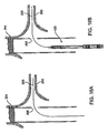
- the outer sheath 160 is retracted in a direction shown by the arrow 238 so that as the open distal end of the sheath 160 moves closer to the compressed location of the distal coiled nitinol hoop 156 and distal ring (hoop) stop 150 ( Fig. 15B ). As the outer sheath 160 is further retracted, the distal coiled nitinol hoop 156 is allowed to expand to its unconstrained diameter configuration and is no longer axially constrained by distal ring hoop stop 150 which remains fixed to the catheter outer member ( Fig. 15C , 16E ).
- the distal hoop may be necessary to move the central members of the catheter assembly forward (or distally) so that the proximal ring stop 152 is brought into close proximity to the location of the main vessel stent graft wall 250 opening 266 having a hoop, grommet, or radiopaque marker 252 so that when the proximal end of the stent graft system is deployed in engagement with or sealing with the main vessel stent graft wall, the sealing engagement can take place without kinking or a rolling of the main and branch graft materials as ring expansion and opening containing forces equalize at their point of contact.
- the distal balloon may be expanded, if necessary, to maintain position of the catheter during the next step).
- the central inner and outer members 122, 144 can be moved in a direction shown by arrow 240, 244 ( Fig. 15E , 16F . respectively) once the proximal ring stop 152 is in position (close to, but inside the main vessel branch opening marked by marker 252) the outer sheath 160 can be further retracted as shown by the arrow 238 to release the proximal coiled nitinol hoop 158 from the outer sheath 182 and the axial constraints of the proximal ring hoop stop 152.
- the delivery catheter and guidewire can be removed to leave the branch graft material 138 in a sealing engagement at a ring receiving pocket separation section (sealing section) 153 with the main vessel stent graft wall 250.
- the sequence for providing a branch graft stent system includes placing a guidewire through a main vessel stent graft side opening or fenestration, tracking a delivery catheter containing the stent graft branch device into position, deploying the stent at the distal end of the device, retracting the sheath to initially release the distally located hoop or stent, repositioning the catheter to promote the release of the proximal or hoop sealing stent at the correct location, retracting the catheter to release the proximal hoop, and removing the device.
- An inflatable balloon may or may not be used to re expand the stent or sealing portion in a both balloon expandable and self expanding branch stent graft catheter system.
- Balloon can also be used to expand to expand stent graft opening 250 after branch vessel graft delivery. Note: Balloon can also be used to expand stent graft opening 250 after branch vessel graft delivery.
- a primary graft 270 is disposed in a primary vessel and has a branch graft opening or port 272 constructed of an insert molded (combination molded) silicone ring that includes enhanced radiopacity by use of known flexible radiopaque materials.
- the branch graft assembly 271 can be constructed of a tubular graft material with a proximal support spring (stent) 282 and a distal spring (stent) 284 which in an expanded configuration engages the walls of the renal artery 280.
- the details of the connection feature between the branch graft assembly 271 and the primary graft 270 include structures, as discussed above, including a proximal ring structure 276 and distal ring structure 278 ( Fig. 18 ).
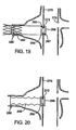
- Figure 19 is an alternate configuration of a branch graft assembly having only a distal spring (stent) 290 engaged with the renal artery 280.
- the proximal ring structure 286 may include a (radiopaque) marker band or portion 287.
- a distal ring structure 288 may include a marker band or portion 289.
- Figure 20 shows an alternate configuration of a branch graft assembly where the branch is constructed of flexible and/or reinforced material having a threaded or ring like or accordion like elements or crimps to span the aneurysmal sac and seal to the inner walls to the renal artery 280.
- the branch graft assembly of Fig. 20 includes a proximal ring structure 296 and a distal ring structure 298 constructed as described in detail above for the balloon expandable and self expanding assemblies.
Description
- This invention relates generally to branch vessel grafts secondarily attached to a main vessel stent graft using a system of rings coupled to the branch graft for a sealed branch vessel graft connection to a main stent graft.
- Prostheses for implantation in blood vessels or other similar organs of the living body are, in general, well known in the medical art. For example, prosthetic vascular grafts formed of biocompatible materials (e.g., Dacron or expanded, porous polytetrafluoroethylene (PTFE) tubing) have been employed to replace or bypass damaged or occluded natural blood vessels. A graft material supported by framework is known as a stent graft. In general, the use of stent grafts for treatment or isolation of vascular aneurysms and vessel walls which have been thinned or thickened by disease (endoluminal repair or exclusion) are well known. Many stent grafts, are "self-expanding", i.e., inserted into the vascular system in a compressed or contracted state, and permitted to expand upon removal of a restraint. Self-expanding stent grafts typically employ a wire or tube configured (e.g. bent or cut) to provide an outward radial force and employ a suitable elastic material such as stainless steel or Nitinol (nickel-titanium). Nitinol may additionally employ shape memory properties. The self-expanding stent graft is typically configured in a tubular shape of a slightly greater diameter than the diameter of the blood vessel in which the stent graft is intended to be used. In general, rather than performing an open surgical procedure which is traumatic and invasive to implant a bypass graft, stents and stent grafts are preferably deployed through a less invasive intraluminal delivery, i.e., cutting through the skin to access a lumen or vasculature or percutaneously via successive dilatation, at a convenient (and less traumatic) entry point, and routing the stent graft through the vascular lumen to the site where the prosthesis is to be deployed.
- Intraluminal deployment is typically effected using a delivery catheter with a coaxial inner (plunger member) and an outer (sheath) tubes arranged for relative axial movement. The stent (or stent graft) is compressed and disposed within the distal end of an outer catheter tube in front of a stent stop fixed to the inner member. The catheter is then maneuvered, typically routed though a lumen (e.g., vessel), until the end of the catheter (and the stent graft) is positioned at the intended treatment site. The stent stop on the inner member is then held stationary while the sheath of the delivery catheter is withdrawn. The inner member prevents the stent graft from being withdrawn with the sheath. As the sheath is withdrawn, the stent graft is released from the confines of the sheath and radially expands so that at least a portion of it is in substantially conforming surface contact with a portion of the surrounding interior of the lumen e.g., blood vessel wall or anatomical conduit. As a convention used to describe the ends of devices implanted in the arterial system the proximal end of the stent graft is the end closest to the heart as taken along the path of blood flow from the heart, whereas the distal end is the end furthest away from the heart once deployed. An example of stent graft positioning and deployment is shown in
Figure 1 , which is a figure taken fromU.S. Patent 5,591,195 to Taheri et al. -
Figure 1 shows ananeurysm 30 in a vascular artery 32 (such as an aorta). Astent graft 34 spanning theaneurysmal sac 36 is show as just having been deployed from adelivery system 38. Thestent graft 34 is constructed of a tubular graft (textile or cloth)material 40 which at each tubular end is radially expanded by zig zag type (Z-type)tubular stents end stents stent graft 34 deployed at the location of theaneurysm 30 creates a separate isolated flow path for blood through the lumen of thestent graft 34 such that theaneurysmal sac 36 of theaneurysm 30 is excluded and is no longer subject to the normal maximum blood pressure experienced in the vascular arterial system at the location of theaneurysm 30. Depending on the construction of thegraft material 40 it may either seal immediately or provide a very slight permeable leakage (blush) which through the biological activity in the blood stream will cause thegraft material 42 to be tightly sealed over time. - Stent grafts can also be used in patients diagnosed with aneurysms close to or crossing branch openings to renal arteries or other branch arteries (e.g., celiac, suprarenal, interior mesenteric). Stent graft designs with side openings are designed for use in regions of the aorta from which side branches feed blood to organs like the kidney, spleen, liver, and stomach.
Figures 2 and 3 show examples fromU.S. Patent 6,030,414 to Taheri , as described therein. Such endovascular grafts have been designed for use where the proximal end of the graft is securely anchored in place, and fenestrations are configured and deployed to avoid blocking or restricting blood flow into the renal arteries. The endovascular graft must be designed, implanted, and maintain position in a manner which does not impair the flow of blood into the branch arteries. -
Stent grafts fenestrations Figures 2 and 3 .Such fenestrations branch artery fenestrations outer surface stent graft 50,60) and the surroundingaortic wall stent graft -
Figure 4 shows an alternate prior art configuration for astent graft 70 having integrally constructedtubular branch members guidewires end 80 fixed by a separately delivered stent (not shown) above the aneurysmal part of the aorta. A full explanation of the mechanism for delivery and final fixation of the stent graft with integral branches (as shown inFig. 4 ) can be had by reference toUS Patent No. 6,099,548 to Taheri the disclosure of which is incorporated herein by reference. -
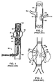
Figures 5 and 6 show an alternate arrangement for construction of a branch vessel connection.Figs. 5 and 6 are examples taken fromUS Patent 6,059,824 to Taheri . InFig. 5 the mainstent body 90 once properly positioned in the main artery (not shown) has an opening wide annularland portion collar 93 aligned with side branching collateral arteries (not shown). The wide annularland portion collar 93 includes a series of inlets (or indentations) 94a, 94b. A collateralcylindrical stent body 92 is mated to the mainstent body 90 through an annular land portion flange located at the proximal end of the collateralcylindrical body 92. The annularland portion collar 95 includesseveral detents collateral collar 95 to position, hold and lock the collateral stentcylindrical body 92 mated to the mainstent body 90. The detents, e.g. 96a, 96b, are received in the inlets e.g. 94a, 94b, of themain stent collar 93. An engagement balloon (not shown) located in the aorta is used to provide the force needed to lock the detents, e.g., 96a, 96b, and the inlets e.g., 94a, 94b, together. -
Figures 7 and 8 show another prior art arrangement of a branch vessel connection to a stent graft. These Figures are similar to those inUS Patent 5,984,955 to Wisselink . Referring now toFigs. 7 and 8 together, aprimary graft 100 includes aring member 104 surrounding aside branch orifice 106 having afrustoconical member 102 extending from thegraft 100. Aside branch orifice 106 is aligned with the location of a branch artery (as seen inFig. 8 ) and then abranch graft 110 is brought in through the main graft and snapped into position as thesmall ring member 114 andlarge ring member 116 at the ends of the taperedproximal portion 112 of thebranch graft 110 are pushed into interfering engagement with thefrustoconical member 102.US 2002/0198585 describes a branched endoluminal goaft similar to the graft shown inFig.7 . - These examples of prior art devices to facilitate flow from an aneurysmal portion of the aorta into branch vessels show the complexity and space/volume requirements needed in the delivery system to deliver and accurately align such prior art systems. The use of fenestrations or openings in a tubular graft requires that a perimeter opening be sealed against the vascular wall to prevent the blood from passing through the tubular graft from continuing to pressurize and enlarge the surrounding aneurysmal sac. Such a main graft a body can be provided with a flange or other fitting which is hard to compress to insert into a delivery catheter for deployment And once the main stent graft body is in position then branch members need to be positioned with great care to provide a blood tight seal between the main graft body and the branch graft.
- Thus, a need exists for a deployment system simplifies alignment and reduces deployment forces needed to make a fluid tight connection between a main stent graft and a branch graft connected to a sidewall thereof. Ideally, such a branch graft is a part of a graft system that can treat aortic aneurysms at a location close to or at the location a smaller vessel branching from the main vessel using a branch that makes a fluid tight connection to a port of the main graft.
- Progress in this field looks to the development of new endovascular grafting systems and methods which a) may be useable for endovascular grafting in regions of a blood vessel (e.g., aorta) from which branch blood vessels (e.g., carotid, innominate, subclavian, intercostal, superior mesenteric, celiac, renal or iliac arteries) extend, and/or b) may enable more aortic aneurysm patients to be considered as candidates for endovascular repair, and/or c) may otherwise advance the state of the art of endovascular grafting to improve patient outcomes or lessen complications.
- A branch graft design according to the present invention provides an improvement in locating and connecting a stent graft to a branch vessel at the location of an aneurysm in the main vessel. A branch graft design includes a tubular branch graft having a proximal end and a distal end and a lumen extending along the tubular branch graft axis longitudinally therethrough. A first self-expanding support ring is coupled to a first annular ring receiving section encircling the tubular branch graft at its proximal end. A second self-expanding support ring is coupled to a second annular ring receiving section circumferentially encircling the tubular branch graft at its proximal end. The second annular ring receiving section is disposed proximally parallel to and a ring receiving section separation length along the branch graft axis from the first annular ring receiving section such that the second annular receiving section is located closer to the distal end of the graft than the first annular ring receiving section. A tubular main graft constructed of a main graft material has a side opening having a perimeter with a substantially flush reinforcing ring or flange. The ring receiving section separation portion of the branch graft material engages the perimeter of the side opening to form a seal between the main graft and the branch graft when the first self expanding support ring which is coupled to the first annular ring receiving section circumferentially encircling the branch graft at the proximal end is disposed inside the side opening of the main graft and the second self expanding support ring is coupled to the second annular ring receiving section circumferentially encircling the graft at the proximal end of the disposed outside a side opening of the branch graft. The support rings may be made ofnitinol and configured in a multiple winding hoop or a stent configuration and the support rings can be sewn to the inside or outside of tubular branch graft. The ring receiving separation portion of the branch graft may be made from the same material as the tubular branch graft or of a semi-rigid (still pliable) material different from the material forming the tubular branch graft.
- The embodiment according to the invention can be further described to include a branch graft delivery system comprising a branch graft disposed on a delivery catheter having a sheath surrounding a seal portion of the branch graft. The seal portion of the branch graft includes a first annular self expanding ring section and a second annular self expanding ring section. The ring sections are circumferentially coupled to the graft at first and second locations, respectively, wherein the first and second locations are spaced from each by a cylindrical channel seal forming section. An inner member of the delivery catheter includes a first stop and a second stop each of which extend laterally outward from the inner member to a diameter slightly less than the inside diameter of the delivery sheath. Annular space between the inside diameter of the sheath and the outside diameter of the inner member provides clearance for the thickness of the graft material to fit through and be carried in the annular space, while preventing the first and second annular self expanding support ring sections which are thicker because they contain or are attached to the support ring member from passing through the annular space. When the sheath is positioned to surround a first stop the first annular self expanding ring section is prevented from moving towards the second annular self expanding ring section and when the sheath is positioned to surround the second stop a second annular self expanding ring section is prevented from moving towards the first expanding ring section.
-
-
Fig. 1 is a schematic cross sectional view of a tubular stent graft of the prior art disposed across an aneurysm in an arterial vessel; -
Fig. 2 is a schematic cross sectional view of a prior art stent graft having fenestrations which match side branch openings in a main arterial passage having branch vessels extending from the main vessel; -
Fig. 3 is a schematic cross sectional view of a stent graft deployed across an aneurysm in an aorta, where the stent graft has fenestrations positioned at locations so that branch vessels are fed through the fenestrations; -
Fig. 4 is a schematic cross section showing a position of a stent graft with several integral side branch graft passages in the process of being positioned to exclude blood flow to the aortic aneurysm while providing an artificial lumen to feed the branch vessels that originate in the area of the aortic aneurysm; -
Figs. 5 and 6 show a pre assembly and post assembly, respectively, pictorial diagram of a main stent body to which a cylindrical collateral stent body is attached in situ; -
Figs. 7A, 7B and 8 show close up and schematic cross sectional diagrams of a branch graft connection to a primary a stent graft providing branching connections in an aorta where an aneurysmal sac has created a widening of the aorta at a location of branch vessels; -
Fig. 9 is a schematic cross sectional view of a balloon expandable branch graft configuration on its delivery system; -
Figs. 10 and l0A are a schematic cross sectional diagram and a close up view of a tip of a self expanding branch graft configuration on its delivery system; -
Figs. 11 and11A are schematic cross sectional diagrams of a set of hoop or ring like self expanding support rings in a compressed configuration; -
Fig. 12 is a schematic cross sectional of the support rings of theFig. 11 in an expanded (post deployed) configuration; -
Figs. 13A and 13B are side perspective diagrams showing a ring type self expanding support ring in a compressed (13A) and an expanded (13B) configuration as pictured inFigs. 11 and 12 , respectively; -
Fig. 14 is schematic cross section showing an alternate configuration of self expanding support rings where the support rings are configured from a stent of a zig zag configuration, the compressed state of the rings is shown; -
Fig. 15A, 15B, 15C ,15D, 15E, 15F, and 15G are schematic cross sectional diagrams showing the progressive steps of deployment of a branch graft assembly; -
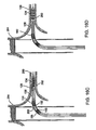
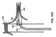
Figs. 16A, 16B ,16C, 16D ,16E, 16F , and16G are schematic cross sectional views of the steps in delivery and deployment of a branch graft into a side branch vessel from a aneurysmal sac where a tubular main graft has already been placed. The steps of deployment as pictured inFigs. 16A-16G provide in situ view of the deployment of the branch graft similar to, though not directly correlating to, the steps of branch deployment pictured inFigs. 15A-15G described above. -
Fig. 17 is a side plan view of a main tubular graft having a side branch opening (fenestration) therein; -
Fig. 18 is a schematic cross sectional view showing one configuration of a side branch graft connected with a tubular main graft; -
Fig. 19 is a schematic cross sectional view showing another configuration of a tubular branch graft connected to a tubular main graft; and -
Fig. 20 is a schematic cross sectional view showing another configuration of a tubular branch graft connected to tubular main graft. -
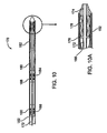
Figure 9 shows a balloon expandable branchgraft stent system 120 in accordance with the invention. A catheter having a catheter inner member (inner tube) 122 extends from aproximal end 124 to adistal end 126 of the catheter. Aballoon 128 is located at thedistal end 126 of the catheter and bonded to the catheterinner member 122 in a balloon to catheter memberdistal bond region 132. The proximal end of theballoon 128 is bonded at a balloon to outer memberproximal bond region 130 to anouter member 144 that provides a coaxial annular lumen between its inner surface and the outer surface of the catheterinner member 122. The balloonexpandable stent 134 compressed around theballoon 128 is positioned between a stent locationproximal marker band 140 and a stent locationdistal marker band 142 both mounted on the catheterinner member 122. Atubular graft material 138 is sewn or bonded to the outside of the stent in a stent to graftmaterial bonding section 136.Tubular graft material 138 extends proximally from thestent 134 to a distal graft ring (hoop-stent) receiving section (pocket) 146 where a self expanding hoop or stent is disposed in a circumferential graft pocket containing a distalcoiled nitinol hoop 156. Anouter sheath 160 prevents the distalcoiled nitinol hoop 156 from expanding in a radial direction while the axial limits of the distal graftring receiving pocket 146 limits the axial movement (expansion) of the distalcoiled nitinol hoop 156. Similarly thegraft 138 at its proximal end contains a proximal graft ring (hoop-stent) receiving section (pocket) 148 such that the axial length of thetubular graft material 138 extends from the proximal end of the proximalgraft ring pocket 148 to the distal end of thestent 134 where it is attached (sewn or bonded) to agraft material 136 in the stent to graftmaterial bonding section 136. A proximalcoiled nitinol hoop 158 is contained within the proximal graft ring hoop receivingsection pocket 148. To maintain the position of theproximal graft pocket 148 with respect to thedistal graft pocket 146 and to the distal end of the stent 134 a proximal ring (hoop) stop 152 and a distal ring (hoop) stop 150 are fixed to the outer member (tube) 144 at a distance between ring (hoop) stops 154 spanned by a graft material identified as a ring receiving pockets separation section (sealing section) 153. The distance between ring hoops stops 154 is dependent upon the main graft wall thickness, the branch vessel diameter, and the main graft wall opening diameter such that the specific dimension described for the distance between hoop ring stops 154 can lengthen or shorten depending on the interaction of the main graft wall thickness the branch vessel diameter and the main graft wall opening and diameter as appropriate for a particular application and branch graft diameter size. Thesealing section 153 may be made of graft material or of a more rigid but still pliable material with good surface contact sealing characteristics. -
Figure 10 is a cross sectional schematic view of a self expanding branchgraft stent system 170. In this system acenter member 172 extends to and is fixed to acatheter tip 174. A stent cup-disc plunger 176 (Fig. 10A ) is attached to thecenter member 172 such that aself expanding stent 178 to which agraft material 180 is attached is disposed between thestent cup plunger 176 and thecatheter tip 174. Afull length sheath 182 covers the full length of thecenter member 172 and seats in a perimeter groove on thecatheter tip 174. Similar to the configuration described for the balloon expandable system above,graft material 180 contains a series of pockets to contain the distal expandable ring (hoop-stent) 184 and a similar ring pocket to contain the proximal expandable ring (hoop-stent) 186. A distal ring (hoop-stent) stop 188 and proximal ring (hoop-stent) stop 190 are fixed to thecenter member 172 to maintain the pre deployment distance between the distal expandable ring (hoop-stent) 184 and the proximal expandable ring (hoop-stent) 186. -
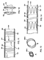
Figure 11 is a close up of a compressed configuration of expandable hoop type ring contained in a branch graft stent system. Anouter sheath 194 contains in a compressed configuration agraft material 196 which is sewn or otherwise bonded topocket material 202 andpocket material 204, respectively. A distal ring hoop pocket seam of the distal pocket shown as a dashedline 206 is the distal limit of the distal pocket containing a compressedcoiled nitinol hoop 198 while a proximal ring hoop pocket seam shown as dashedline 208 of the distal pocket connects thedistal pocket material 202 to thegraft material 196 to act as a closed pouch to contain the compressedcoiled nitinol hoop 198. Similarly a compressed proximalcoiled nitinol hoop 200 is contained within a hoop pocket (pouch) formed byproximal pocket material 204 which is bonded or sewn to thegraft material 196 at coaxial circumferentially ring hoop pocket seams, i.e., distal seam of theproximal pocket 210, and proximal seam of theproximal pocket 212. A ring receiving pocket separation (seal)section 214 separates the distal seam of theproximal pocket 210 from the proximal seam of thedistal pocket 208. -
Figure 11A is a close up of an alternate compressed configuration of expandable hoop type ring contained in a branch graft stent system of that shown inFigure 11 . An outer sheath 194' contains in a compressed configuration graft material 196' which is sewn or otherwise bonded to pocket of preenlarged material 203 forming a pocket for receiving and setting the maximum diameter of expansion of a compressed coiled nitinol hoop 198'. A distal ring hoop pocket seam of the distal pocket shown as a dashed line 206' in the distal limit of the distal pocket containing a compressedcoiled nitinol hoop 198 while a proximal ring hoop pocket seam shown as dashedline 208' of the distal pocket connects thedistal pocket material 202 to the graft material 196' to act as a closed pouch to contain the compressed coiled nitinol hoop 198'. In this instance the graft material 196' which extends between the distal and proximal ring hoop pocket seams 206' and 208' has a bulge (disk creating) diameter which results in an annular fold of graft material that is folded over when the adjacent graft material (as shown inFigure 11A ) or tucked inside and not shown as seen or not seen inFigure 11 . such that stretching of the graft material by the expanding ring (e.g., 198') is not needed and does not take place. The angled (or tipped over) orientation of the compressed coiled nitinol hoop 198' shown inFigure 11A , shows the position of the end of the hoop in the end of thepocket 203, as might be experienced if a fully expanded hoop in a graft material pocket were compressed to fit into a delivery sheath (e.g., 194'). -
Figure. 12 shows configuration of the coilednitinol hoops 98, 200 in an expanded configuration. Thesheath 194 shown inFig. 11 having been retracted, thedistal nitinol hoop 198 has expanded from its compressed configuration as isolated inFig. 13A shown as 198(c) to an expanded configuration as shown inFig. 13B identified by 198(e). The proximalcoiled nitinol hoop 200 is similarly expanded so that the two expanded hoops within the hoop pocket spaces act as expanding discs along the length of the graft material and create an expanding or sealing area at the ring receiving pocket separation section 214 (which may be very short length and have a diameter as large as if not larger than, the main graft opening to which it is intended to seal). -
Figure 14 shows a self expanding configuration of a self expanding ring stent configuration. Anouter sheath 217 contains in a compressed configuration agraft material 218 inside of which, or on the outside of which, is attached or sewn in place a set of distal (220) and proximal (222) Z-type self expanding stents. The stents can be sewn to the inside or outside of the graft material or a pocket of material or pocket (pouch)space self expanding stents pockets graft material 218 includes a ring receiving pocket separation (seal)section 236 between the twocentral pockets seam 230, 232. - One sequence for deployment of a branch graft to be sealed to an opening in a main graft will now discussed by reference to
Figs. 15A-G and16A-G . Irrespective of whether a balloon expandable stent or a self expanding stent is used to anchor the distal end of the graft material in the branch vessel, such a stent can be used solely to anchor the graft or be used multifunctionally to anchor the graft and treat and provide a lesion opening function when there is an occlusion or narrowing in the branch vessel into which the branch graft system is being placed. - As can be seen in
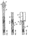
Fig. 16A a main vesselendovascular device 264 has been placed across an aneurysm. Theendovascular device 264 includes a side branch opening 266 through which aguidewire 260 is threaded into the lumen contained by thebranch vessel wall 262. The balloon expandable branchgraft stent system 120 is advanced over theguidewire 260 as seenFig. 16B ,16C , and on into through the branch vessel while continuing to follow the track provided by theguidewire 260 into a position where the radiopaque images of the distal ring (hoop) stop 150 and proximal (hoop) stop 152 straddle the opening 266 (marked by radiopaque markers or some other radiopaque visible marking scheme). - The branch
graft stent system 120 extending into the branch vessel hasgraft material 138 and astent 134 compressed on a balloon 128 (Fig. 16C ). Once in position (according to the ring stops 150, 152 discussed above) theballoon 128 is inflated such that the bondedsection 136 of the graft material sewn or bonded to the outside of thestent 134 comes into engagement with the branch vessel wall 262 (Fig. 15A ,16D ). Theouter sheath 160 is retracted in a direction shown by thearrow 238 so that as the open distal end of thesheath 160 moves closer to the compressed location of the distalcoiled nitinol hoop 156 and distal ring (hoop) stop 150 (Fig. 15B ). As theouter sheath 160 is further retracted, the distalcoiled nitinol hoop 156 is allowed to expand to its unconstrained diameter configuration and is no longer axially constrained by distal ring hoop stop 150 which remains fixed to the catheter outer member (Fig. 15C ,16E ). Once the distal hoop is expanded it may be necessary to move the central members of the catheter assembly forward (or distally) so that theproximal ring stop 152 is brought into close proximity to the location of the main vesselstent graft wall 250opening 266 having a hoop, grommet, orradiopaque marker 252 so that when the proximal end of the stent graft system is deployed in engagement with or sealing with the main vessel stent graft wall, the sealing engagement can take place without kinking or a rolling of the main and branch graft materials as ring expansion and opening containing forces equalize at their point of contact. (Once repositioning of the catheter to improve proximal alignment has occurred, the distal balloon may be expanded, if necessary, to maintain position of the catheter during the next step). The central inner andouter members arrow 240, 244 (Fig. 15E ,16F . respectively) once theproximal ring stop 152 is in position (close to, but inside the main vessel branch opening marked by marker 252) theouter sheath 160 can be further retracted as shown by thearrow 238 to release the proximalcoiled nitinol hoop 158 from theouter sheath 182 and the axial constraints of the proximalring hoop stop 152. (Fig. 15F ,16G ). Once the branch graft system has been deployed the delivery catheter and guidewire can be removed to leave thebranch graft material 138 in a sealing engagement at a ring receiving pocket separation section (sealing section) 153 with the main vesselstent graft wall 250. - The sequence for providing a branch graft stent system includes placing a guidewire through a main vessel stent graft side opening or fenestration, tracking a delivery catheter containing the stent graft branch device into position, deploying the stent at the distal end of the device, retracting the sheath to initially release the distally located hoop or stent, repositioning the catheter to promote the release of the proximal or hoop sealing stent at the correct location, retracting the catheter to release the proximal hoop, and removing the device. An inflatable balloon may or may not be used to re expand the stent or sealing portion in a both balloon expandable and self expanding branch stent graft catheter system. Balloon can also be used to expand to expand
stent graft opening 250 after branch vessel graft delivery. Note: Balloon can also be used to expandstent graft opening 250 after branch vessel graft delivery. - Referring now to
Figs. 17, 18 ,19, and 20 , aprimary graft 270 is disposed in a primary vessel and has a branch graft opening orport 272 constructed of an insert molded (combination molded) silicone ring that includes enhanced radiopacity by use of known flexible radiopaque materials. Thebranch graft assembly 271 can be constructed of a tubular graft material with a proximal support spring (stent) 282 and a distal spring (stent) 284 which in an expanded configuration engages the walls of therenal artery 280. The details of the connection feature between thebranch graft assembly 271 and theprimary graft 270 include structures, as discussed above, including aproximal ring structure 276 and distal ring structure 278 (Fig. 18 ). -
Figure 19 is an alternate configuration of a branch graft assembly having only a distal spring (stent) 290 engaged with therenal artery 280. Theproximal ring structure 286 may include a (radiopaque) marker band orportion 287. Similarly, adistal ring structure 288 may include a marker band orportion 289. -
Figure 20 shows an alternate configuration of a branch graft assembly where the branch is constructed of flexible and/or reinforced material having a threaded or ring like or accordion like elements or crimps to span the aneurysmal sac and seal to the inner walls to therenal artery 280. The branch graft assembly ofFig. 20 includes aproximal ring structure 296 and adistal ring structure 298 constructed as described in detail above for the balloon expandable and self expanding assemblies.
Claims (13)
- A branch graft design, comprising
a tubular branch graft having a proximal end (124), a distal end (126) and a lumen extending along a tubular branch graft axis longitudinally therethrough;
a first support ring (158) coupled to a first annular ring receiving section (148) circumferentially encircling said graft at said proximal end (124); and
a second support ring (156) coupled to a second annular ring receiving section (146) circumferentially encircling said graft at said proximal end (124);
wherein said second annular ring receiving section (146) is disposed approximately parallel to and a ring receiving section separation length along said graft axis from said first annular ring receiving section (148), wherein said second annular receiving section (146) is located closer to said distal end of said graft than said first annular ring receiving section (148);
a tubular main graft (264) having main graft material with a side opening (266) having a perimeter;
wherein a ring receiving section separation portion (153) of said branch graft material engages said perimeter of said side opening (266) to form a seal between the main graft (264) and the branch graft when said first support ring (158) coupled to said first annular ring receiving section (148) circumferentially encircling said graft at said proximal end is disposed inside said side opening (264) of said main graft and second support ring (156) coupled to said second annular ring receiving section (146) circumferentially encircling said graft at said proximal end is disposed outside said side opening of said main graft (264), characterised in that said first (158) and second (156) support rings are self expanding rings. - The branch graft design of claim 1, wherein at least one among the first ring (158) and the second ring (156) are a nitinol hoop or of a similar material with shape memory characteristics.
- The branch graft design of claim 1, wherein at least one among the first ring (158) and the second ring (156) are a nitinol stent or of a similar material with shape memory characteristics.
- The branch graft design of claim 1, wherein at least one among the first ring (158) and the second ring (156) are sewn to an inside of the tubular branch graft.
- The branch graft design of claim 1, wherein at least one among the first ring (158) and the second ring (156) are sewn to an outside of the tubular graft.
- The branch graft design of claim 1, wherein the ring receiving separation portion (153) is made from said graft material forming the tubular branch graft.
- The branch graft design of claim 1, wherein the ring receiving separation portion (153) is made from a semi-rigid material different from said material forming the tubular graft.
- The branch graft design of claim 1 wherein at least one among the branch graft and the main graft (264) is at least partially formed from materials selected from the group of materials comprising woven polyester, expanded polytetrafluoroethylene, and Dacron.
- The branch design of claim 1, further wherein said side opening (266) includes a port member (272).
- The branch graft design of claim 1, wherein the port member (272) is a ring element substantially flush with an outer surface of the main graft (264).
- The branch graft design of claim 1, wherein the branch graft further comprises a branch graft anchoring component (284) for holding at least the distal end of the branch graft in contact with the wall of the branch anatomical conduit (280).
- The branch graft design of claim 1, further comprising a sheath (160) constraining the branch graft that forms one side of a flexible seal when the sheath (160) is withdrawn to a first position to expose the second ring and further forms a second side of the flexible seal when the sheath is withdrawn further to expose the first ring.
- A branch graft delivery system (120) comprising:a branch graft according to any of the preceding claims disposed on a delivery catheter (122), said catheter having a sheath (160) surrounding a seal portion of said branch graft;wherein an inner member (122) of said delivery catheter includes a first stop (152) and a second stop (154) which extend laterally outward from the inner member (122) to a diameter slightly less than an inner diameter of said sheath (160), such that an annular space is enough to provide clearance for the thickness of the graft material to fit through the annular space, while preventing the first and second annular self expanding ring sections (158, 156) from passing through these annular spaces, wherein when said sheath (160) is positioned to surround said first stop (152), said first annular self expanding ring section (158) is prevented from moving towards said second annular self expanding ring section (156) and when said sheath (160) is positioned to surround said second stop (154), said second annular self expanding ring section (156) is prevented from moving towards said first self expanding ring section (158).
Applications Claiming Priority (2)
| Application Number | Priority Date | Filing Date | Title |
|---|---|---|---|
| US11/035,230 US7306623B2 (en) | 2005-01-13 | 2005-01-13 | Branch vessel graft design and deployment method |
| PCT/US2006/000998 WO2006076441A1 (en) | 2005-01-13 | 2006-01-11 | Branch vessel graft design and deployment method |
Publications (2)
| Publication Number | Publication Date |
|---|---|
| EP1853198A1 EP1853198A1 (en) | 2007-11-14 |
| EP1853198B1 true EP1853198B1 (en) | 2013-03-06 |
Family
ID=36283973
Family Applications (1)
| Application Number | Title | Priority Date | Filing Date |
|---|---|---|---|
| EP06718112A Not-in-force EP1853198B1 (en) | 2005-01-13 | 2006-01-11 | Branch vessel graft design |
Country Status (5)
| Country | Link |
|---|---|
| US (2) | US7306623B2 (en) |
| EP (1) | EP1853198B1 (en) |
| JP (1) | JP4694575B2 (en) |
| ES (1) | ES2416343T3 (en) |
| WO (1) | WO2006076441A1 (en) |
Families Citing this family (133)
| Publication number | Priority date | Publication date | Assignee | Title |
|---|---|---|---|---|
| US7491232B2 (en) | 1998-09-18 | 2009-02-17 | Aptus Endosystems, Inc. | Catheter-based fastener implantation apparatus and methods with implantation force resolution |
| US20090138072A1 (en) * | 2001-11-28 | 2009-05-28 | Michael William Gendreau | Devices, systems, and methods for endovascular staple and/or prosthesis delivery and implantation |
| US7147657B2 (en) | 2003-10-23 | 2006-12-12 | Aptus Endosystems, Inc. | Prosthesis delivery systems and methods |
| US20070073389A1 (en) | 2001-11-28 | 2007-03-29 | Aptus Endosystems, Inc. | Endovascular aneurysm devices, systems, and methods |
| US20050177180A1 (en) | 2001-11-28 | 2005-08-11 | Aptus Endosystems, Inc. | Devices, systems, and methods for supporting tissue and/or structures within a hollow body organ |
| US8231639B2 (en) | 2001-11-28 | 2012-07-31 | Aptus Endosystems, Inc. | Systems and methods for attaching a prosthesis within a body lumen or hollow organ |
| US20090099650A1 (en) * | 2001-11-28 | 2009-04-16 | Lee Bolduc | Devices, systems, and methods for endovascular staple and/or prosthesis delivery and implantation |
| CN100479786C (en) | 2001-11-28 | 2009-04-22 | 阿普特斯内系统公司 | Endovascular aneurysm repair system |
| US9320503B2 (en) | 2001-11-28 | 2016-04-26 | Medtronic Vascular, Inc. | Devices, system, and methods for guiding an operative tool into an interior body region |
| US7147661B2 (en) | 2001-12-20 | 2006-12-12 | Boston Scientific Santa Rosa Corp. | Radially expandable stent |
| BRPI0516955A (en) * | 2004-09-24 | 2008-09-30 | Ingeneus Inc | genetic assay |
| US8128680B2 (en) | 2005-01-10 | 2012-03-06 | Taheri Laduca Llc | Apparatus and method for deploying an implantable device within the body |
| US8287583B2 (en) | 2005-01-10 | 2012-10-16 | Taheri Laduca Llc | Apparatus and method for deploying an implantable device within the body |
| US20060155366A1 (en) * | 2005-01-10 | 2006-07-13 | Laduca Robert | Apparatus and method for deploying an implantable device within the body |
| US20060247760A1 (en) * | 2005-04-29 | 2006-11-02 | Medtronic Vascular, Inc. | Methods and apparatus for treatment of aneurysms adjacent branch arteries |
| US8961586B2 (en) | 2005-05-24 | 2015-02-24 | Inspiremd Ltd. | Bifurcated stent assemblies |
| US10070977B2 (en) | 2005-05-24 | 2018-09-11 | Inspire M.D. Ltd | Stent apparatuses for treatment via body lumens and methods of use |
| US8043323B2 (en) | 2006-10-18 | 2011-10-25 | Inspiremd Ltd. | In vivo filter assembly |
| WO2007028112A2 (en) * | 2005-09-02 | 2007-03-08 | Medtronic Vascular, Inc. | Methods and apparatus for treatment of aneurysms adjacent to branch arteries |
| US8343028B2 (en) * | 2005-10-19 | 2013-01-01 | Thoratec Corporation | Ventricular pump coupling |
| CN101466316B (en) | 2005-10-20 | 2012-06-27 | 阿普特斯内系统公司 | Devices systems and methods for prosthesis delivery and implantation including the use of a fastener tool |
| DE602006014204D1 (en) * | 2005-12-29 | 2010-06-17 | Med Inst Inc | ENDOLUMINAL DEVICE COMPRISING A MECHANISM FOR PROXIMAL OR DISTAL FASTENING AND CLOSURE AND USE METHOD THEREFOR |
| US7914572B2 (en) * | 2006-02-13 | 2011-03-29 | William A. Cook Australia Pty. Ltd. | Side branch stent graft construction |
| EP1991164B1 (en) | 2006-02-28 | 2017-06-14 | Angiomed GmbH & Co. Medizintechnik KG | Flexible stretch stent-graft |
| US20070219622A1 (en) * | 2006-03-17 | 2007-09-20 | Cook Incorporated | Stent-graft structure having one or more stent pockets |
| US9757260B2 (en) | 2006-03-30 | 2017-09-12 | Medtronic Vascular, Inc. | Prosthesis with guide lumen |
| US7678141B2 (en) * | 2006-04-18 | 2010-03-16 | Medtronic Vascular, Inc. | Stent graft having a flexible, articulable, and axially compressible branch graft |
| US20080039926A1 (en) | 2006-08-11 | 2008-02-14 | Majercak David C | Stent graft sealing zone connecting structure |
| US10137015B2 (en) | 2006-10-18 | 2018-11-27 | Inspiremd Ltd. | Knitted stent jackets |
| WO2008053469A2 (en) * | 2006-10-29 | 2008-05-08 | Alon Shalev | An extra-vascular wrapping for treating aneurysmatic aorta and methods thereof |
| US7771467B2 (en) * | 2006-11-03 | 2010-08-10 | The Cleveland Clinic Foundation | Apparatus for repairing the function of a native aortic valve |
| CN101578078B (en) | 2006-11-22 | 2013-01-02 | 印斯拜尔Md有限公司 | Optimized stent jacket |
| US8187315B1 (en) | 2006-12-08 | 2012-05-29 | Cardica, Inc. | Partial stent for treatment of a vascular aneurysm |
| US8216298B2 (en) * | 2007-01-05 | 2012-07-10 | Medtronic Vascular, Inc. | Branch vessel graft method and delivery system |
| JP2010517703A (en) | 2007-02-09 | 2010-05-27 | タヘリ ラドュカ エルエルシー | Vascular graft and method for processing the same |
| BRPI0807261B8 (en) | 2007-02-09 | 2021-06-22 | Taheri Laduca Llc | stent-loaded catheter sets |
| CN101715329B (en) * | 2007-03-05 | 2012-11-14 | 恩多斯潘有限公司 | Multi-component expandable supportive bifurcated endoluminal grafts and methods for using same |
| US20080228256A1 (en) | 2007-03-13 | 2008-09-18 | Medtronic Vascular, Inc. | Braided Flange Branch Graft for Branch Vessel |
| US8715336B2 (en) * | 2007-04-19 | 2014-05-06 | Medtronic Vascular, Inc. | Methods and apparatus for treatment of aneurysms adjacent to branch arteries |
| US20090030502A1 (en) * | 2007-07-26 | 2009-01-29 | Jichao Sun | Socket For Fenestrated Tubular Prosthesis |
| US8252035B2 (en) * | 2007-08-01 | 2012-08-28 | Cappella, Inc. | Device delivery system with two stage withdrawal |
| US8486131B2 (en) | 2007-12-15 | 2013-07-16 | Endospan Ltd. | Extra-vascular wrapping for treating aneurysmatic aorta in conjunction with endovascular stent-graft and methods thereof |
| US20090164001A1 (en) * | 2007-12-21 | 2009-06-25 | Biggs David P | Socket For Fenestrated Tubular Prosthesis |
| US8221494B2 (en) | 2008-02-22 | 2012-07-17 | Endologix, Inc. | Apparatus and method of placement of a graft or graft system |
| US20090264985A1 (en) * | 2008-04-17 | 2009-10-22 | Medtronic Vascular, Inc. | Branch Vessel Suture Stent System and Method |
| EP2633823B1 (en) | 2008-04-21 | 2016-06-01 | Covidien LP | Braid-ball embolic devices and delivery systems |
| US9675482B2 (en) | 2008-05-13 | 2017-06-13 | Covidien Lp | Braid implant delivery systems |
| WO2010024867A1 (en) * | 2008-08-27 | 2010-03-04 | Cleveland Clinic Foundation | Stent graft fixation coupling |
| US8353943B2 (en) * | 2008-08-29 | 2013-01-15 | Cook Medical Technologies Llc | Variable weave graft with metal strand reinforcement for in situ fenestration |
| WO2010044854A1 (en) * | 2008-10-16 | 2010-04-22 | Aptus Endosystems, Inc. | Devices, systems, and methods for endovascular staple and/or prosthesis delivery and implantation |
| EP2349086B1 (en) | 2008-10-16 | 2017-03-22 | Medtronic Vascular, Inc. | Devices and systems for endovascular staple and/or prosthesis delivery and implantation |
| US8052741B2 (en) * | 2009-03-23 | 2011-11-08 | Medtronic Vascular, Inc. | Branch vessel prosthesis with a roll-up sealing assembly |
| US8506622B2 (en) * | 2009-04-17 | 2013-08-13 | Medtronic Vascular, Inc. | Mobile external coupling for branch vessel connection |
| US8540764B2 (en) * | 2009-04-17 | 2013-09-24 | Medtronic Vascular, Inc. | Mobile external coupling for branch vessel connection |
| WO2010127040A1 (en) | 2009-04-28 | 2010-11-04 | Endologix, Inc. | Apparatus and method of placement of a graft or graft system |
| US8162975B2 (en) * | 2009-05-08 | 2012-04-24 | Medtronic Vascular, Inc. | Systems and methods for closing a percutaneous vascular puncture |
| US8858613B2 (en) | 2010-09-20 | 2014-10-14 | Altura Medical, Inc. | Stent graft delivery systems and associated methods |
| WO2010150208A2 (en) | 2009-06-23 | 2010-12-29 | Endospan Ltd. | Vascular prostheses for treating aneurysms |
| US8979892B2 (en) | 2009-07-09 | 2015-03-17 | Endospan Ltd. | Apparatus for closure of a lumen and methods of using the same |
| CA2768228C (en) * | 2009-07-14 | 2015-08-18 | Endospan Ltd. | Sideport engagement and sealing mechanism for endoluminal stent-grafts |
| US9095456B2 (en) | 2009-10-13 | 2015-08-04 | Cook Medical Technologies Llc | Paraplegia prevention stent graft |
| EP2387374B1 (en) | 2009-10-13 | 2016-03-16 | Cook Medical Technologies LLC | Paraplegia prevention stent graft |
| WO2011051812A1 (en) * | 2009-10-28 | 2011-05-05 | UNIVERSITE DE STRASBOURG (Etablissement Public National à Caractère Scientifique, Culturel et Professionnel) | Endoprosthesis comprising at least one collateral branch attached to a pre-established window |
| CN102740807B (en) | 2009-11-30 | 2015-11-25 | 恩多斯潘有限公司 | For implantation into the multi-part overlay film frame system had in the blood vessel of multiple branch |
| CA2782385A1 (en) | 2009-12-01 | 2011-06-09 | Altura Medical, Inc. | Modular endograft devices and associated systems and methods |
| WO2011070576A1 (en) | 2009-12-08 | 2011-06-16 | Endospan Ltd. | Endovascular stent-graft system with fenestrated and crossing stent-grafts |
| WO2011080738A1 (en) | 2009-12-31 | 2011-07-07 | Endospan Ltd. | Endovascular flow direction indicator |
| US9468442B2 (en) | 2010-01-28 | 2016-10-18 | Covidien Lp | Vascular remodeling device |
| WO2011095979A1 (en) | 2010-02-08 | 2011-08-11 | Endospan Ltd. | Thermal energy application for prevention and management of endoleaks in stent-grafts |
| US8979824B2 (en) | 2010-06-21 | 2015-03-17 | Boston Scientific Scimed, Inc. | Stent delivery system having retention structure |
| US8808348B2 (en) * | 2010-06-23 | 2014-08-19 | Boston Scientific Scimed, Inc. | Delivery system having stent retention structure |
| IT1401467B1 (en) * | 2010-06-25 | 2013-07-26 | Sambusseti | ORTHOTOPIC ENDOPROSTHESIS OF ARTIFICIAL BLADDER |
| JP6261339B2 (en) | 2010-11-02 | 2018-01-17 | エンドロジックス、インク | Apparatus and method for placement of a graft or graft system |
| US9566149B2 (en) | 2010-11-16 | 2017-02-14 | W. L. Gore & Associates, Inc. | Devices and methods for in situ fenestration of a stent-graft at the site of a branch vessel |
| EP2579810A4 (en) | 2011-02-03 | 2014-07-30 | Endospan Ltd | Implantable medical devices constructed of shape memory material |
| CN103442653B (en) | 2011-02-11 | 2016-06-01 | 柯惠有限合伙公司 | Two benches launches aneurysma embolization device |
| US9855046B2 (en) | 2011-02-17 | 2018-01-02 | Endospan Ltd. | Vascular bands and delivery systems therefor |
| EP2680788A4 (en) | 2011-03-02 | 2014-12-10 | Endospan Ltd | Reduced-strain extra- vascular ring for treating aortic aneurysm |
| WO2012134990A1 (en) | 2011-03-25 | 2012-10-04 | Tyco Healthcare Group Lp | Vascular remodeling device |
| US9839542B2 (en) | 2011-04-19 | 2017-12-12 | Medtronic Ardian Luxembourg S.A.R.L. | Mobile external coupling for branch vessel connection |
| EP2517671B1 (en) | 2011-04-28 | 2016-05-11 | Cook Medical Technologies LLC | Apparatus for facilitating deployment of an endoluminal prosthesis |
| GB201109317D0 (en) * | 2011-06-03 | 2011-07-20 | Vascutek Ltd | Stent element |
| US8574287B2 (en) | 2011-06-14 | 2013-11-05 | Endospan Ltd. | Stents incorporating a plurality of strain-distribution locations |
| ES2568377T3 (en) | 2011-06-21 | 2016-04-28 | Endospan Ltd | Endovascular system with circumferentially overlapping stents |
| EP2729095B1 (en) * | 2011-07-07 | 2016-10-26 | Endospan Ltd. | Stent fixation with reduced plastic deformation |
| US9314328B2 (en) | 2011-08-16 | 2016-04-19 | W. L. Gore & Associates, Inc. | Branched stent graft device and deployment |
| US9839510B2 (en) | 2011-08-28 | 2017-12-12 | Endospan Ltd. | Stent-grafts with post-deployment variable radial displacement |
| WO2013049448A1 (en) | 2011-09-29 | 2013-04-04 | Covidien Lp | Vascular remodeling device |
| WO2013065040A1 (en) | 2011-10-30 | 2013-05-10 | Endospan Ltd. | Triple-collar stent-graft |
| US8728148B2 (en) | 2011-11-09 | 2014-05-20 | Cook Medical Technologies Llc | Diameter reducing tie arrangement for endoluminal prosthesis |
| CN102488575A (en) * | 2011-11-11 | 2012-06-13 | 许尚栋 | Aortic windowing stent |
| EP2785277B1 (en) | 2011-12-04 | 2017-04-05 | Endospan Ltd. | Branched stent-graft system |
| CA3051684C (en) | 2011-12-06 | 2020-06-16 | Aortic Innovations Llc | Device for endovascular aortic repair and method of using the same |
| US9095421B2 (en) | 2012-04-18 | 2015-08-04 | Medtronic Vascular, Inc. | Multi-leaflet coupling for branch vessel connection |
| US9393140B2 (en) | 2012-04-27 | 2016-07-19 | Medtronic Vascular, Inc. | Reconfigurable stent-graft delivery system and method of use |
| US9737394B2 (en) | 2012-04-27 | 2017-08-22 | Medtronic Vascular, Inc. | Stent-graft prosthesis for placement in the abdominal aorta |
| US10098767B2 (en) | 2012-04-27 | 2018-10-16 | Medtronic Vascular, Inc. | Reconfigurable stent-graft delivery system and method of use |
| US8968384B2 (en) | 2012-04-27 | 2015-03-03 | Medtronic Vascular, Inc. | Circumferentially constraining sutures for a stent-graft |
| US9452069B2 (en) | 2012-04-27 | 2016-09-27 | Medtronic Vascular, Inc. | Reconfigurable stent-graft delivery system and method of use |
| US9811613B2 (en) | 2012-05-01 | 2017-11-07 | University Of Washington Through Its Center For Commercialization | Fenestration template for endovascular repair of aortic aneurysms |
| US9770350B2 (en) | 2012-05-15 | 2017-09-26 | Endospan Ltd. | Stent-graft with fixation elements that are radially confined for delivery |
| US10285833B2 (en) | 2012-08-10 | 2019-05-14 | Lombard Medical Limited | Stent delivery systems and associated methods |
| FR2995206B1 (en) | 2012-09-11 | 2014-09-26 | Univ Strasbourg | TREATMENT KIT, TREATMENT DEVICE AND METHOD FOR MANUFACTURING THE SAME |
| US9314248B2 (en) | 2012-11-06 | 2016-04-19 | Covidien Lp | Multi-pivot thrombectomy device |
| WO2014108895A2 (en) | 2013-01-08 | 2014-07-17 | Endospan Ltd. | Minimization of stent-graft migration during implantation |
| US9295571B2 (en) * | 2013-01-17 | 2016-03-29 | Covidien Lp | Methods and apparatus for luminal stenting |
| US9668892B2 (en) | 2013-03-11 | 2017-06-06 | Endospan Ltd. | Multi-component stent-graft system for aortic dissections |
| US9402751B2 (en) | 2013-03-13 | 2016-08-02 | W. L. Gore & Associates, Inc. | Devices and methods for treatment of the aortic arch |
| US9463105B2 (en) | 2013-03-14 | 2016-10-11 | Covidien Lp | Methods and apparatus for luminal stenting |
| CN108433769B (en) | 2013-03-15 | 2021-06-08 | 柯惠有限合伙公司 | Occlusion device |
| US9737426B2 (en) | 2013-03-15 | 2017-08-22 | Altura Medical, Inc. | Endograft device delivery systems and associated methods |
| WO2015075708A1 (en) | 2013-11-19 | 2015-05-28 | Endospan Ltd. | Stent system with radial-expansion locking |
| EP3068339B1 (en) | 2014-12-18 | 2017-11-01 | Endospan Ltd. | Endovascular stent-graft with fatigue-resistant lateral tube |
| JP2018524025A (en) | 2015-06-30 | 2018-08-30 | エンドロジックス、インク | Lock assembly for coupling guidewire to delivery system |
| US10478194B2 (en) | 2015-09-23 | 2019-11-19 | Covidien Lp | Occlusive devices |
| JP6841848B2 (en) * | 2016-06-13 | 2021-03-10 | アオーティカ コーポレイション | Systems, devices and methods for marking and / or reinforcing fenestrations in prosthetic implants |
| CN106175982B (en) * | 2016-06-29 | 2018-11-30 | 中国人民解放军广州军区武汉总医院 | The conveying release device of cardiac stent and cardiac stent |
| WO2018026768A1 (en) * | 2016-08-02 | 2018-02-08 | Aortica Corporation | Systems, devices, and methods for coupling a prosthetic implant to a fenestrated body |
| WO2018156850A1 (en) | 2017-02-24 | 2018-08-30 | Bolton Medical, Inc. | Stent graft with fenestration lock |
| ES2863978T3 (en) | 2017-02-24 | 2021-10-13 | Bolton Medical Inc | System for radially constricting a stent graft |
| WO2018156849A1 (en) | 2017-02-24 | 2018-08-30 | Bolton Medical, Inc. | Vascular prosthesis with fenestration ring and methods of use |
| WO2018156847A1 (en) | 2017-02-24 | 2018-08-30 | Bolton Medical, Inc. | Delivery system and method to radially constrict a stent graft |
| WO2018156851A1 (en) | 2017-02-24 | 2018-08-30 | Bolton Medical, Inc. | Vascular prosthesis with moveable fenestration |
| WO2018156848A1 (en) | 2017-02-24 | 2018-08-30 | Bolton Medical, Inc. | Vascular prosthesis with crimped adapter and methods of use |
| EP3585320B1 (en) | 2017-02-24 | 2022-07-27 | Bolton Medical, Inc. | Delivery system for radially constricting a stent graft |
| WO2019060816A2 (en) | 2017-09-25 | 2019-03-28 | Aortica Corporation | Systems, devices, and methods for coupling a prosthetic implant to a fenestrated body |
| JP7168566B2 (en) | 2017-10-31 | 2022-11-09 | ボルトン メディカル インコーポレイテッド | Distal torque component, delivery system and method of use |
| US11872146B2 (en) * | 2018-03-23 | 2024-01-16 | Sanford Health | Aortic filter and flow diverter and methods for use thereof |
| DE102018111614A1 (en) * | 2018-05-15 | 2019-11-21 | Jörg Teßarek | Multi-lumen implant |
| US11484423B2 (en) | 2018-08-21 | 2022-11-01 | Cook Medical Technologies Llc | Apparatuses to facilitate prosthesis placement |
| JP2022525788A (en) | 2019-03-20 | 2022-05-19 | インキュベート メディカル テクノロジーズ、 エルエルシー | Aortic dissection implant |
| EP3989876A4 (en) * | 2019-06-25 | 2023-07-05 | Atrium Medical Corporation | Stent device including a flarable crown |
| US11324583B1 (en) | 2021-07-06 | 2022-05-10 | Archo Medical LTDA | Multi-lumen stent-graft and related surgical methods |
Family Cites Families (42)
| Publication number | Priority date | Publication date | Assignee | Title |
|---|---|---|---|---|
| JPS6028434Y2 (en) * | 1980-06-16 | 1985-08-28 | 建部 容保 | Artificial blood vessel |
| US4728328A (en) * | 1984-10-19 | 1988-03-01 | Research Corporation | Cuffed tubular organic prostheses |
| US5123917A (en) * | 1990-04-27 | 1992-06-23 | Lee Peter Y | Expandable intraluminal vascular graft |
| US5151105A (en) * | 1991-10-07 | 1992-09-29 | Kwan Gett Clifford | Collapsible vessel sleeve implant |
| ATE247435T1 (en) * | 1992-05-08 | 2003-09-15 | Schneider Usa Inc | STENT FOR THE OESOPHAGUS |
| US5306294A (en) * | 1992-08-05 | 1994-04-26 | Ultrasonic Sensing And Monitoring Systems, Inc. | Stent construction of rolled configuration |
| ATE310839T1 (en) * | 1994-04-29 | 2005-12-15 | Scimed Life Systems Inc | STENT WITH COLLAGEN |
| US5522881A (en) * | 1994-06-28 | 1996-06-04 | Meadox Medicals, Inc. | Implantable tubular prosthesis having integral cuffs |
| US5709713A (en) * | 1995-03-31 | 1998-01-20 | Cardiovascular Concepts, Inc. | Radially expansible vascular prosthesis having reversible and other locking structures |
| US5807398A (en) * | 1995-04-28 | 1998-09-15 | Shaknovich; Alexander | Shuttle stent delivery catheter |
| WO1996037167A1 (en) * | 1995-05-25 | 1996-11-28 | Raychem Corporation | Stent assembly |
| GB9518400D0 (en) * | 1995-09-08 | 1995-11-08 | Anson Medical Ltd | A surgical graft/stent system |
| US6193745B1 (en) * | 1995-10-03 | 2001-02-27 | Medtronic, Inc. | Modular intraluminal prosteheses construction and methods |
| US5591195A (en) * | 1995-10-30 | 1997-01-07 | Taheri; Syde | Apparatus and method for engrafting a blood vessel |
| US5843166A (en) * | 1997-01-17 | 1998-12-01 | Meadox Medicals, Inc. | Composite graft-stent having pockets for accomodating movement |
| US5984955A (en) * | 1997-09-11 | 1999-11-16 | Wisselink; Willem | System and method for endoluminal grafting of bifurcated or branched vessels |
| US6074416A (en) * | 1997-10-09 | 2000-06-13 | St. Jude Medical Cardiovascular Group, Inc. | Wire connector structures for tubular grafts |
| US6030414A (en) * | 1997-11-13 | 2000-02-29 | Taheri; Syde A. | Variable stent and method for treatment of arterial disease |
| US6395018B1 (en) * | 1998-02-09 | 2002-05-28 | Wilfrido R. Castaneda | Endovascular graft and process for bridging a defect in a main vessel near one of more branch vessels |
| US6352543B1 (en) * | 2000-04-29 | 2002-03-05 | Ventrica, Inc. | Methods for forming anastomoses using magnetic force |
| US6361559B1 (en) * | 1998-06-10 | 2002-03-26 | Converge Medical, Inc. | Thermal securing anastomosis systems |
| US6099548A (en) * | 1998-07-28 | 2000-08-08 | Taheri; Syde A. | Apparatus and method for deploying an aortic arch graft |
| US6059824A (en) * | 1998-12-23 | 2000-05-09 | Taheri; Syde A. | Mated main and collateral stent and method for treatment of arterial disease |
| US20020198585A1 (en) * | 1999-10-05 | 2002-12-26 | Willem Wisselink | System and method for edoluminal grafting of bifurcated or branched vessels |
| US6652567B1 (en) * | 1999-11-18 | 2003-11-25 | David H. Deaton | Fenestrated endovascular graft |
| US6241764B1 (en) * | 2000-01-26 | 2001-06-05 | Cabg Medical, Inc. | Stented grafts for coupling vascular members |
| US6585762B1 (en) * | 2000-08-10 | 2003-07-01 | Paul Stanish | Arteriovenous grafts and methods of implanting the same |
| WO2002056799A2 (en) * | 2001-01-19 | 2002-07-25 | Boston Scientific Limited | Introducer for deployment of branched prosthesis |
| US6451045B1 (en) * | 2001-02-22 | 2002-09-17 | Alsius Corporation | Heat exchange catheter having a helically wrapped heat exchanger |
| FR2822370B1 (en) * | 2001-03-23 | 2004-03-05 | Perouse Lab | TUBULAR ENDOPROSTHESIS COMPRISING A DEFORMABLE RING AND REQUIRED OF INTERVENTION FOR ITS IMPLANTATION |
| US6994722B2 (en) * | 2001-07-03 | 2006-02-07 | Scimed Life Systems, Inc. | Implant having improved fixation to a body lumen and method for implanting the same |
| AUPR847201A0 (en) * | 2001-10-26 | 2001-11-15 | Cook Incorporated | Endoluminal graft |
| US6989024B2 (en) * | 2002-02-28 | 2006-01-24 | Counter Clockwise, Inc. | Guidewire loaded stent for delivery through a catheter |
| EP1513470A2 (en) * | 2002-05-28 | 2005-03-16 | The Cleveland Clinic Foundation | Minimally invasive treatment system for aortic aneurysms |
| US20040243221A1 (en) * | 2003-05-27 | 2004-12-02 | Fawzi Natalie V. | Endovascular graft including substructure for positioning and sealing within vasculature |
| US7241308B2 (en) * | 2003-06-09 | 2007-07-10 | Xtent, Inc. | Stent deployment systems and methods |
| US7201772B2 (en) * | 2003-07-08 | 2007-04-10 | Ventor Technologies, Ltd. | Fluid flow prosthetic device |
| US9974674B2 (en) * | 2003-11-08 | 2018-05-22 | Cook Medical Technologies Llc | Branch vessel prothesis with positional indicator system and method |
| JP4852033B2 (en) * | 2004-03-11 | 2012-01-11 | トリバスキュラー インコーポレイテッド | Modular endovascular graft |
| US8034096B2 (en) * | 2004-03-31 | 2011-10-11 | Cook Medical Technologies Llc | Stent-graft with graft to graft attachment |
| US20050273154A1 (en) * | 2004-06-08 | 2005-12-08 | Colone William M | Bifurcated stent graft and apparatus for making same |
| ATE477768T1 (en) * | 2004-09-21 | 2010-09-15 | Cook William A Australia | STENT PROSTHESIS CONNECTION ARRANGEMENT |
-
2005
- 2005-01-13 US US11/035,230 patent/US7306623B2/en active Active
-
2006
- 2006-01-11 JP JP2007551358A patent/JP4694575B2/en not_active Expired - Fee Related
- 2006-01-11 ES ES06718112T patent/ES2416343T3/en active Active
- 2006-01-11 WO PCT/US2006/000998 patent/WO2006076441A1/en active Application Filing
- 2006-01-11 EP EP06718112A patent/EP1853198B1/en not_active Not-in-force
-
2007
- 2007-10-30 US US11/928,535 patent/US7575590B2/en not_active Expired - Fee Related
Also Published As
| Publication number | Publication date |
|---|---|
| US7306623B2 (en) | 2007-12-11 |
| US20080058918A1 (en) | 2008-03-06 |
| WO2006076441A1 (en) | 2006-07-20 |
| EP1853198A1 (en) | 2007-11-14 |
| ES2416343T3 (en) | 2013-07-31 |
| JP2008526440A (en) | 2008-07-24 |
| JP4694575B2 (en) | 2011-06-08 |
| US20060155359A1 (en) | 2006-07-13 |
| US7575590B2 (en) | 2009-08-18 |
Similar Documents
| Publication | Publication Date | Title |
|---|---|---|
| EP1853198B1 (en) | Branch vessel graft design | |
| EP1517651B1 (en) | Thoracic aortic aneurysm stent graft | |
| EP1684668B1 (en) | Aorta and branch vessel stent grafts and system | |
| US8216298B2 (en) | Branch vessel graft method and delivery system | |
| EP1441782B1 (en) | Interlocking endoluminal stent-graft | |
| US6676699B2 (en) | Stent graft with integrated valve device and method | |
| EP1000590B1 (en) | An improved stent which is easly recaptured and repositioned within the body | |
| EP2429450B1 (en) | Mobile external coupling for branch vessel connection | |
| US20100305686A1 (en) | Low-profile modular abdominal aortic aneurysm graft | |
| WO2011159324A1 (en) | Side branch stent graft | |
| US20040111148A1 (en) | Bifurcated endoluminal prosthetic assembly and method | |
| US20050033416A1 (en) | Vascular graft and deployment system |
Legal Events
| Date | Code | Title | Description |
|---|---|---|---|
| PUAI | Public reference made under article 153(3) epc to a published international application that has entered the european phase |
Free format text: ORIGINAL CODE: 0009012 |
|
| 17P | Request for examination filed |
Effective date: 20070813 |
|
| AK | Designated contracting states |
Kind code of ref document: A1 Designated state(s): AT BE BG CH CY CZ DE DK EE ES FI FR GB GR HU IE IS IT LI LT LU LV MC NL PL PT RO SE SI SK TR |
|
| DAX | Request for extension of the european patent (deleted) | ||
| 17Q | First examination report despatched |
Effective date: 20100923 |
|
| GRAP | Despatch of communication of intention to grant a patent |
Free format text: ORIGINAL CODE: EPIDOSNIGR1 |
|
| GRAS | Grant fee paid |
Free format text: ORIGINAL CODE: EPIDOSNIGR3 |
|
| GRAA | (expected) grant |
Free format text: ORIGINAL CODE: 0009210 |
|
| AK | Designated contracting states |
Kind code of ref document: B1 Designated state(s): AT BE BG CH CY CZ DE DK EE ES FI FR GB GR HU IE IS IT LI LT LU LV MC NL PL PT RO SE SI SK TR |
|
| REG | Reference to a national code |
Ref country code: GB Ref legal event code: FG4D |
|
| REG | Reference to a national code |
Ref country code: CH Ref legal event code: EP Ref country code: AT Ref legal event code: REF Ref document number: 599171 Country of ref document: AT Kind code of ref document: T Effective date: 20130315 |
|
| REG | Reference to a national code |
Ref country code: IE Ref legal event code: FG4D |
|
| REG | Reference to a national code |
Ref country code: DE Ref legal event code: R096 Ref document number: 602006034894 Country of ref document: DE Effective date: 20130502 |
|
| REG | Reference to a national code |
Ref country code: AT Ref legal event code: MK05 Ref document number: 599171 Country of ref document: AT Kind code of ref document: T Effective date: 20130306 |
|
| PG25 | Lapsed in a contracting state [announced via postgrant information from national office to epo] |
Ref country code: BG Free format text: LAPSE BECAUSE OF FAILURE TO SUBMIT A TRANSLATION OF THE DESCRIPTION OR TO PAY THE FEE WITHIN THE PRESCRIBED TIME-LIMIT Effective date: 20130606 Ref country code: AT Free format text: LAPSE BECAUSE OF FAILURE TO SUBMIT A TRANSLATION OF THE DESCRIPTION OR TO PAY THE FEE WITHIN THE PRESCRIBED TIME-LIMIT Effective date: 20130306 Ref country code: SE Free format text: LAPSE BECAUSE OF FAILURE TO SUBMIT A TRANSLATION OF THE DESCRIPTION OR TO PAY THE FEE WITHIN THE PRESCRIBED TIME-LIMIT Effective date: 20130306 Ref country code: LT Free format text: LAPSE BECAUSE OF FAILURE TO SUBMIT A TRANSLATION OF THE DESCRIPTION OR TO PAY THE FEE WITHIN THE PRESCRIBED TIME-LIMIT Effective date: 20130306 |
|
| REG | Reference to a national code |
Ref country code: NL Ref legal event code: VDEP Effective date: 20130306 |
|
| REG | Reference to a national code |
Ref country code: LT Ref legal event code: MG4D |
|
| PG25 | Lapsed in a contracting state [announced via postgrant information from national office to epo] |
Ref country code: GR Free format text: LAPSE BECAUSE OF FAILURE TO SUBMIT A TRANSLATION OF THE DESCRIPTION OR TO PAY THE FEE WITHIN THE PRESCRIBED TIME-LIMIT Effective date: 20130607 Ref country code: SI Free format text: LAPSE BECAUSE OF FAILURE TO SUBMIT A TRANSLATION OF THE DESCRIPTION OR TO PAY THE FEE WITHIN THE PRESCRIBED TIME-LIMIT Effective date: 20130306 Ref country code: FI Free format text: LAPSE BECAUSE OF FAILURE TO SUBMIT A TRANSLATION OF THE DESCRIPTION OR TO PAY THE FEE WITHIN THE PRESCRIBED TIME-LIMIT Effective date: 20130306 Ref country code: LV Free format text: LAPSE BECAUSE OF FAILURE TO SUBMIT A TRANSLATION OF THE DESCRIPTION OR TO PAY THE FEE WITHIN THE PRESCRIBED TIME-LIMIT Effective date: 20130306 |
|
| PG25 | Lapsed in a contracting state [announced via postgrant information from national office to epo] |
Ref country code: BE Free format text: LAPSE BECAUSE OF FAILURE TO SUBMIT A TRANSLATION OF THE DESCRIPTION OR TO PAY THE FEE WITHIN THE PRESCRIBED TIME-LIMIT Effective date: 20130306 |
|
| PG25 | Lapsed in a contracting state [announced via postgrant information from national office to epo] |
Ref country code: PT Free format text: LAPSE BECAUSE OF FAILURE TO SUBMIT A TRANSLATION OF THE DESCRIPTION OR TO PAY THE FEE WITHIN THE PRESCRIBED TIME-LIMIT Effective date: 20130708 Ref country code: EE Free format text: LAPSE BECAUSE OF FAILURE TO SUBMIT A TRANSLATION OF THE DESCRIPTION OR TO PAY THE FEE WITHIN THE PRESCRIBED TIME-LIMIT Effective date: 20130306 Ref country code: CZ Free format text: LAPSE BECAUSE OF FAILURE TO SUBMIT A TRANSLATION OF THE DESCRIPTION OR TO PAY THE FEE WITHIN THE PRESCRIBED TIME-LIMIT Effective date: 20130306 Ref country code: RO Free format text: LAPSE BECAUSE OF FAILURE TO SUBMIT A TRANSLATION OF THE DESCRIPTION OR TO PAY THE FEE WITHIN THE PRESCRIBED TIME-LIMIT Effective date: 20130306 Ref country code: IS Free format text: LAPSE BECAUSE OF FAILURE TO SUBMIT A TRANSLATION OF THE DESCRIPTION OR TO PAY THE FEE WITHIN THE PRESCRIBED TIME-LIMIT Effective date: 20130706 Ref country code: SK Free format text: LAPSE BECAUSE OF FAILURE TO SUBMIT A TRANSLATION OF THE DESCRIPTION OR TO PAY THE FEE WITHIN THE PRESCRIBED TIME-LIMIT Effective date: 20130306 Ref country code: NL Free format text: LAPSE BECAUSE OF FAILURE TO SUBMIT A TRANSLATION OF THE DESCRIPTION OR TO PAY THE FEE WITHIN THE PRESCRIBED TIME-LIMIT Effective date: 20130306 |
|
| PG25 | Lapsed in a contracting state [announced via postgrant information from national office to epo] |
Ref country code: PL Free format text: LAPSE BECAUSE OF FAILURE TO SUBMIT A TRANSLATION OF THE DESCRIPTION OR TO PAY THE FEE WITHIN THE PRESCRIBED TIME-LIMIT Effective date: 20130306 Ref country code: CY Free format text: LAPSE BECAUSE OF FAILURE TO SUBMIT A TRANSLATION OF THE DESCRIPTION OR TO PAY THE FEE WITHIN THE PRESCRIBED TIME-LIMIT Effective date: 20130306 |
|
| PLBE | No opposition filed within time limit |
Free format text: ORIGINAL CODE: 0009261 |
|
| STAA | Information on the status of an ep patent application or granted ep patent |
Free format text: STATUS: NO OPPOSITION FILED WITHIN TIME LIMIT |
|
| PG25 | Lapsed in a contracting state [announced via postgrant information from national office to epo] |
Ref country code: DK Free format text: LAPSE BECAUSE OF FAILURE TO SUBMIT A TRANSLATION OF THE DESCRIPTION OR TO PAY THE FEE WITHIN THE PRESCRIBED TIME-LIMIT Effective date: 20130306 |
|
| 26N | No opposition filed |
Effective date: 20131209 |
|
| REG | Reference to a national code |
Ref country code: DE Ref legal event code: R097 Ref document number: 602006034894 Country of ref document: DE Effective date: 20131209 |
|
| PG25 | Lapsed in a contracting state [announced via postgrant information from national office to epo] |
Ref country code: MC Free format text: LAPSE BECAUSE OF FAILURE TO SUBMIT A TRANSLATION OF THE DESCRIPTION OR TO PAY THE FEE WITHIN THE PRESCRIBED TIME-LIMIT Effective date: 20130306 Ref country code: LU Free format text: LAPSE BECAUSE OF FAILURE TO SUBMIT A TRANSLATION OF THE DESCRIPTION OR TO PAY THE FEE WITHIN THE PRESCRIBED TIME-LIMIT Effective date: 20140111 |
|
| REG | Reference to a national code |
Ref country code: CH Ref legal event code: PL |
|
| GBPC | Gb: european patent ceased through non-payment of renewal fee |
Effective date: 20140111 |
|
| PG25 | Lapsed in a contracting state [announced via postgrant information from national office to epo] |
Ref country code: CH Free format text: LAPSE BECAUSE OF NON-PAYMENT OF DUE FEES Effective date: 20140131 Ref country code: LI Free format text: LAPSE BECAUSE OF NON-PAYMENT OF DUE FEES Effective date: 20140131 |
|
| REG | Reference to a national code |
Ref country code: IE Ref legal event code: MM4A |
|
| PG25 | Lapsed in a contracting state [announced via postgrant information from national office to epo] |
Ref country code: GB Free format text: LAPSE BECAUSE OF NON-PAYMENT OF DUE FEES Effective date: 20140111 |
|
| PG25 | Lapsed in a contracting state [announced via postgrant information from national office to epo] |
Ref country code: IE Free format text: LAPSE BECAUSE OF NON-PAYMENT OF DUE FEES Effective date: 20140111 |
|
| REG | Reference to a national code |
Ref country code: FR Ref legal event code: PLFP Year of fee payment: 11 |
|
| PG25 | Lapsed in a contracting state [announced via postgrant information from national office to epo] |
Ref country code: TR Free format text: LAPSE BECAUSE OF FAILURE TO SUBMIT A TRANSLATION OF THE DESCRIPTION OR TO PAY THE FEE WITHIN THE PRESCRIBED TIME-LIMIT Effective date: 20130306 Ref country code: HU Free format text: LAPSE BECAUSE OF FAILURE TO SUBMIT A TRANSLATION OF THE DESCRIPTION OR TO PAY THE FEE WITHIN THE PRESCRIBED TIME-LIMIT; INVALID AB INITIO Effective date: 20060111 |
|
| REG | Reference to a national code |
Ref country code: FR Ref legal event code: PLFP Year of fee payment: 12 |
|
| REG | Reference to a national code |
Ref country code: FR Ref legal event code: PLFP Year of fee payment: 13 |
|
| PGFP | Annual fee paid to national office [announced via postgrant information from national office to epo] |
Ref country code: IT Payment date: 20190102 Year of fee payment: 14 Ref country code: ES Payment date: 20190201 Year of fee payment: 14 |
|
| PG25 | Lapsed in a contracting state [announced via postgrant information from national office to epo] |
Ref country code: IT Free format text: LAPSE BECAUSE OF NON-PAYMENT OF DUE FEES Effective date: 20200111 |
|
| PGFP | Annual fee paid to national office [announced via postgrant information from national office to epo] |
Ref country code: FR Payment date: 20201217 Year of fee payment: 16 |
|
| PGFP | Annual fee paid to national office [announced via postgrant information from national office to epo] |
Ref country code: DE Payment date: 20201217 Year of fee payment: 16 |
|
| REG | Reference to a national code |
Ref country code: ES Ref legal event code: FD2A Effective date: 20210603 |
|
| PG25 | Lapsed in a contracting state [announced via postgrant information from national office to epo] |
Ref country code: ES Free format text: LAPSE BECAUSE OF NON-PAYMENT OF DUE FEES Effective date: 20200112 |
|
| REG | Reference to a national code |
Ref country code: DE Ref legal event code: R119 Ref document number: 602006034894 Country of ref document: DE |
|
| PG25 | Lapsed in a contracting state [announced via postgrant information from national office to epo] |
Ref country code: DE Free format text: LAPSE BECAUSE OF NON-PAYMENT OF DUE FEES Effective date: 20220802 |
|
| PG25 | Lapsed in a contracting state [announced via postgrant information from national office to epo] |
Ref country code: FR Free format text: LAPSE BECAUSE OF NON-PAYMENT OF DUE FEES Effective date: 20220131 |