EP1855392A2 - Interleaver and deinterleaver for use in a diversity transmission communication system - Google Patents
Interleaver and deinterleaver for use in a diversity transmission communication system Download PDFInfo
- Publication number
- EP1855392A2 EP1855392A2 EP07014757A EP07014757A EP1855392A2 EP 1855392 A2 EP1855392 A2 EP 1855392A2 EP 07014757 A EP07014757 A EP 07014757A EP 07014757 A EP07014757 A EP 07014757A EP 1855392 A2 EP1855392 A2 EP 1855392A2
- Authority
- EP
- European Patent Office
- Prior art keywords
- signal
- data symbols
- walsh
- symbols
- streams
- Prior art date
- Legal status (The legal status is an assumption and is not a legal conclusion. Google has not performed a legal analysis and makes no representation as to the accuracy of the status listed.)
- Granted
Links
- 230000005540 biological transmission Effects 0.000 title claims abstract description 96
- 238000004891 communication Methods 0.000 title claims description 29
- 238000000034 method Methods 0.000 claims description 36
- 230000007480 spreading Effects 0.000 claims description 23
- 238000012937 correction Methods 0.000 claims description 20
- 230000003111 delayed effect Effects 0.000 claims description 5
- 230000001360 synchronised effect Effects 0.000 claims description 2
- 230000002596 correlated effect Effects 0.000 abstract description 11
- 230000007423 decrease Effects 0.000 abstract 1
- 238000005562 fading Methods 0.000 description 8
- 238000001228 spectrum Methods 0.000 description 8
- 239000000969 carrier Substances 0.000 description 6
- 230000001413 cellular effect Effects 0.000 description 4
- 238000000926 separation method Methods 0.000 description 4
- 238000010586 diagram Methods 0.000 description 3
- VJYFKVYYMZPMAB-UHFFFAOYSA-N ethoprophos Chemical compound CCCSP(=O)(OCC)SCCC VJYFKVYYMZPMAB-UHFFFAOYSA-N 0.000 description 3
- 238000012545 processing Methods 0.000 description 3
- 230000002441 reversible effect Effects 0.000 description 3
- 230000015556 catabolic process Effects 0.000 description 2
- 238000006731 degradation reaction Methods 0.000 description 2
- 230000001934 delay Effects 0.000 description 2
- 238000013461 design Methods 0.000 description 2
- 230000003247 decreasing effect Effects 0.000 description 1
- 230000009977 dual effect Effects 0.000 description 1
- 230000000694 effects Effects 0.000 description 1
- 238000005516 engineering process Methods 0.000 description 1
- 230000002708 enhancing effect Effects 0.000 description 1
- 239000011159 matrix material Substances 0.000 description 1
- 230000000116 mitigating effect Effects 0.000 description 1
- 230000008569 process Effects 0.000 description 1
- 230000004044 response Effects 0.000 description 1
- 230000002123 temporal effect Effects 0.000 description 1
Images

Classifications
-
- H—ELECTRICITY
- H04—ELECTRIC COMMUNICATION TECHNIQUE
- H04B—TRANSMISSION
- H04B7/00—Radio transmission systems, i.e. using radiation field
- H04B7/02—Diversity systems; Multi-antenna system, i.e. transmission or reception using multiple antennas
- H04B7/04—Diversity systems; Multi-antenna system, i.e. transmission or reception using multiple antennas using two or more spaced independent antennas
- H04B7/06—Diversity systems; Multi-antenna system, i.e. transmission or reception using multiple antennas using two or more spaced independent antennas at the transmitting station
- H04B7/0697—Diversity systems; Multi-antenna system, i.e. transmission or reception using multiple antennas using two or more spaced independent antennas at the transmitting station using spatial multiplexing
-
- H—ELECTRICITY
- H03—ELECTRONIC CIRCUITRY
- H03M—CODING; DECODING; CODE CONVERSION IN GENERAL
- H03M13/00—Coding, decoding or code conversion, for error detection or error correction; Coding theory basic assumptions; Coding bounds; Error probability evaluation methods; Channel models; Simulation or testing of codes
- H03M13/27—Coding, decoding or code conversion, for error detection or error correction; Coding theory basic assumptions; Coding bounds; Error probability evaluation methods; Channel models; Simulation or testing of codes using interleaving techniques
-
- H—ELECTRICITY
- H04—ELECTRIC COMMUNICATION TECHNIQUE
- H04B—TRANSMISSION
- H04B1/00—Details of transmission systems, not covered by a single one of groups H04B3/00 - H04B13/00; Details of transmission systems not characterised by the medium used for transmission
- H04B1/69—Spread spectrum techniques
- H04B1/707—Spread spectrum techniques using direct sequence modulation
-
- H—ELECTRICITY
- H04—ELECTRIC COMMUNICATION TECHNIQUE
- H04B—TRANSMISSION
- H04B7/00—Radio transmission systems, i.e. using radiation field
- H04B7/02—Diversity systems; Multi-antenna system, i.e. transmission or reception using multiple antennas
- H04B7/04—Diversity systems; Multi-antenna system, i.e. transmission or reception using multiple antennas using two or more spaced independent antennas
- H04B7/06—Diversity systems; Multi-antenna system, i.e. transmission or reception using multiple antennas using two or more spaced independent antennas at the transmitting station
- H04B7/0613—Diversity systems; Multi-antenna system, i.e. transmission or reception using multiple antennas using two or more spaced independent antennas at the transmitting station using simultaneous transmission
- H04B7/0667—Diversity systems; Multi-antenna system, i.e. transmission or reception using multiple antennas using two or more spaced independent antennas at the transmitting station using simultaneous transmission of delayed versions of same signal
- H04B7/0671—Diversity systems; Multi-antenna system, i.e. transmission or reception using multiple antennas using two or more spaced independent antennas at the transmitting station using simultaneous transmission of delayed versions of same signal using different delays between antennas
-
- H—ELECTRICITY
- H04—ELECTRIC COMMUNICATION TECHNIQUE
- H04B—TRANSMISSION
- H04B7/00—Radio transmission systems, i.e. using radiation field
- H04B7/02—Diversity systems; Multi-antenna system, i.e. transmission or reception using multiple antennas
- H04B7/04—Diversity systems; Multi-antenna system, i.e. transmission or reception using multiple antennas using two or more spaced independent antennas
- H04B7/06—Diversity systems; Multi-antenna system, i.e. transmission or reception using multiple antennas using two or more spaced independent antennas at the transmitting station
- H04B7/0613—Diversity systems; Multi-antenna system, i.e. transmission or reception using multiple antennas using two or more spaced independent antennas at the transmitting station using simultaneous transmission
- H04B7/0678—Diversity systems; Multi-antenna system, i.e. transmission or reception using multiple antennas using two or more spaced independent antennas at the transmitting station using simultaneous transmission using different spreading codes between antennas
-
- H—ELECTRICITY
- H04—ELECTRIC COMMUNICATION TECHNIQUE
- H04B—TRANSMISSION
- H04B7/00—Radio transmission systems, i.e. using radiation field
- H04B7/02—Diversity systems; Multi-antenna system, i.e. transmission or reception using multiple antennas
- H04B7/04—Diversity systems; Multi-antenna system, i.e. transmission or reception using multiple antennas using two or more spaced independent antennas
- H04B7/08—Diversity systems; Multi-antenna system, i.e. transmission or reception using multiple antennas using two or more spaced independent antennas at the receiving station
- H04B7/0891—Space-time diversity
- H04B7/0894—Space-time diversity using different delays between antennas
-
- H—ELECTRICITY
- H04—ELECTRIC COMMUNICATION TECHNIQUE
- H04L—TRANSMISSION OF DIGITAL INFORMATION, e.g. TELEGRAPHIC COMMUNICATION
- H04L1/00—Arrangements for detecting or preventing errors in the information received
- H04L1/004—Arrangements for detecting or preventing errors in the information received by using forward error control
- H04L1/0056—Systems characterized by the type of code used
- H04L1/0071—Use of interleaving
-
- H—ELECTRICITY
- H04—ELECTRIC COMMUNICATION TECHNIQUE
- H04L—TRANSMISSION OF DIGITAL INFORMATION, e.g. TELEGRAPHIC COMMUNICATION
- H04L1/00—Arrangements for detecting or preventing errors in the information received
- H04L1/02—Arrangements for detecting or preventing errors in the information received by diversity reception
- H04L1/06—Arrangements for detecting or preventing errors in the information received by diversity reception using space diversity
-
- H—ELECTRICITY
- H03—ELECTRONIC CIRCUITRY
- H03M—CODING; DECODING; CODE CONVERSION IN GENERAL
- H03M13/00—Coding, decoding or code conversion, for error detection or error correction; Coding theory basic assumptions; Coding bounds; Error probability evaluation methods; Channel models; Simulation or testing of codes
- H03M13/03—Error detection or forward error correction by redundancy in data representation, i.e. code words containing more digits than the source words
- H03M13/05—Error detection or forward error correction by redundancy in data representation, i.e. code words containing more digits than the source words using block codes, i.e. a predetermined number of check bits joined to a predetermined number of information bits
- H03M13/09—Error detection only, e.g. using cyclic redundancy check [CRC] codes or single parity bit
-
- H—ELECTRICITY
- H03—ELECTRONIC CIRCUITRY
- H03M—CODING; DECODING; CODE CONVERSION IN GENERAL
- H03M13/00—Coding, decoding or code conversion, for error detection or error correction; Coding theory basic assumptions; Coding bounds; Error probability evaluation methods; Channel models; Simulation or testing of codes
- H03M13/03—Error detection or forward error correction by redundancy in data representation, i.e. code words containing more digits than the source words
- H03M13/23—Error detection or forward error correction by redundancy in data representation, i.e. code words containing more digits than the source words using convolutional codes, e.g. unit memory codes
-
- H—ELECTRICITY
- H03—ELECTRONIC CIRCUITRY
- H03M—CODING; DECODING; CODE CONVERSION IN GENERAL
- H03M13/00—Coding, decoding or code conversion, for error detection or error correction; Coding theory basic assumptions; Coding bounds; Error probability evaluation methods; Channel models; Simulation or testing of codes
- H03M13/29—Coding, decoding or code conversion, for error detection or error correction; Coding theory basic assumptions; Coding bounds; Error probability evaluation methods; Channel models; Simulation or testing of codes combining two or more codes or code structures, e.g. product codes, generalised product codes, concatenated codes, inner and outer codes
- H03M13/2957—Turbo codes and decoding
-
- H—ELECTRICITY
- H04—ELECTRIC COMMUNICATION TECHNIQUE
- H04B—TRANSMISSION
- H04B2201/00—Indexing scheme relating to details of transmission systems not covered by a single group of H04B3/00 - H04B13/00
- H04B2201/69—Orthogonal indexing scheme relating to spread spectrum techniques in general
- H04B2201/707—Orthogonal indexing scheme relating to spread spectrum techniques in general relating to direct sequence modulation
- H04B2201/7097—Direct sequence modulation interference
- H04B2201/709709—Methods of preventing interference
-
- H—ELECTRICITY
- H04—ELECTRIC COMMUNICATION TECHNIQUE
- H04L—TRANSMISSION OF DIGITAL INFORMATION, e.g. TELEGRAPHIC COMMUNICATION
- H04L1/00—Arrangements for detecting or preventing errors in the information received
- H04L1/004—Arrangements for detecting or preventing errors in the information received by using forward error control
- H04L1/0041—Arrangements at the transmitter end
Definitions
- the current invention relates to wireless telecommunications. More particularly, the present invention relates to a novel and improved transmitter design for enhancing the reliability of communications in a wireless communications system.
- CDMA code division multiple access
- TDMA time division multiple access
- FDMA frequency division multiple access
- AM modulation schemes such as amplitude companded single sideband (ACSSB)
- TDMA time division multiple access
- FDMA frequency division multiple access
- ACSB AM modulation schemes
- CDMA spread spectrum modulation technique
- Code division multiple access communications systems have been standardized in the United States in Telecommunications Industry Association TIA/EIA/IS-95-A, entitled "MOBILE STATION-BASE STATION COMPATIBILITY STANDARD FOR DUAL-MODE WIDEBAND SPREAD SPECTRUM CELLULAR SYSTEM", hereafter referred to as IS-95 and incorporated by reference herein.
- the CDMA waveform by its inherent nature of being a wideband signal, offers a form of frequency diversity by spreading the signal energy over a wide bandwidth. Therefore, frequency selective fading affects only a small part of the CDMA signal bandwidth.
- Space or path diversity on the forward or reverse link is obtained by providing multiple signal paths through simultaneous links to or from a mobile user through two or more antennas, cell sectors or cell-sites.
- path diversity may be obtained by exploiting the multipath environment through spread spectrum processing by allowing a signal arriving with different propagation delays to be received and processed separately. Examples of the utilization of path diversity are illustrated in U.S. Patent No. 5,101,501 entitled “SOFT HANDOFF IN A CDMA CELLULAR TELEPHONE SYSTEM", and U.S. Patent No. 5,109,390 entitled “DIVERSITY RECEIVER IN A CDMA CELLULAR TELEPHONE SYSTEM", both assigned to the assignee of the present invention and incorporated by reference herein.
- the PN chip interval defines the minimum separation two paths must have in order to be combined.
- the relative arrival times (or offsets) of the paths in the received signal must first be determined. The demodulator performs this function by "searching" through a sequence of offsets and measuring the energy received at each offset. If the energy associated with a potential offset exceeds a certain threshold, a demodulation element, or "finger" may be assigned to that offset. The signal present at that path offset can then be summed with the contributions of other fingers at their respective offsets.
- PN I and PN Q are distinct PN spreading codes and I' and Q' are two channels being spread at the transmitter.
- the International Telecommunications Union recently requested the submission of proposed methods for providing high rate data and high-quality speech services over wireless communication channels.
- a first of these proposals was issued by the Telecommunications Industry Association, entitled “The cdma2000 ITU-R RTT Candidate submission”.
- a second of these proposals was issued by the European Telecommunications Standards Institute (ETSI), entitled “The ETSI UMTS Terrestrial Radio Access (UTRA) ITU-R RTT Candidate submission”.
- ETSI European Telecommunications Standards Institute
- UTRA ETSI UMTS Terrestrial Radio Access
- UTRA UWC-136 Candidate submission
- CDMA's broadband nature permits the demodulation of signals having traversed different propagation paths.
- U.S Patent Nos. 5,280,472 , 5,513,176 , 5,553,011 assigned to the assignee of the present invention and incorporated by reference herein, the usage of multiple sets of distributed antennas is employed to deliberately provide multiple paths of propagation.
- sets of antennas are fed by a common signal with only time delay processing to distinguish signals.
- the transmit output of the base station is fed to a string of antenna elements for example with a coaxial cable.
- the antenna elements connect to the cable using power splitters.
- the resulting signals, amplified and frequency converted as necessary, are fed to the antennas.
- Antenna transmit diversity as well as multi-carrier transmission are promising new technologies that improve transmission resistance to fading by offering space and/or frequency diversity.
- the data to be transmitted is encoded into symbols, which are then distributed among the antennas and transmitted.
- Such techniques include delay transmit diversity, orthogonal transmit diversity (OTD), time switched transmit diversity (TSTD), time delayed transmit diversity (TDTD), and multi-carrier transmit diversity (MCTD).
- OTD orthogonal transmit diversity
- TSTD time switched transmit diversity
- TDTD time delayed transmit diversity
- MCTD multi-carrier transmit diversity
- 08/929,380 entitled “Method and Apparatus for Transmitting and Receiving Data Multiplexed onto Multiple Code Channels, Frequencies and Base Stations", filed September 15, 1997, assigned to the assignee of the present invention and incorporated by reference herein, describes a matrix of methods for transmitting CDMA signals using multiple carriers and multiple code channels for introducing diversity into the transmitted signal.
- the multi-carrier transmission whether it uses antenna transmit diversity or not, must distribute the coded symbols among the different carriers, which is similar to distributing symbols among several antennas in an antenna transmit diversity system.
- the channels utilizing the two carriers may still be thought of as independent transmission channels which may or may not suffer from correlated fading.
- Correlated fading is the phenomenon whereby each of the transmissions suffers degradation in a temporally correlated fashion.
- the current invention enhances the performance of a system utilizing interleaving and transmit diversity by reordering the sequence of symbols transmitted along the different transmission channels. For example, in the case of a system using two transmission channels, the symbols being transmitted on one channel are shuffled with respect to the symbols transmitted through the other channel. This shuffling makes it less likely that successive symbols output by the interleaver are lost to correlated fading in the two transmission channels.
- a source frame F is composed of N coded symbols Si (1 ⁇ i ⁇ N).
- these symbols Si are distributed over M transmitters (different carriers or antennas or beth).
- the current invention splits the symbols into M groups Gj (1 ⁇ j ⁇ M), one for each transmitter. Then each of the groups, Gj, is interleaved independently.
- the goal of the shuffle is to make sure that even if the different transmission paths from the different transmitters become correlated, the performance degradation is minor.
- One particularly efficient implementation of the shuffle that each shuffle cyclically rotates the symbols it receives.
- each shuffle cyclically rotates the symbols it receives.
- Shuffler j cyclically rotate the symbols to be transmitted by transmitter j by (j-1)*N/M symbols.
- N 4
- An alternative embodiment of a shuffler is a flip. This transforms "abcd" into "dcba”.
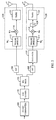
- FIG. 1 shows the present invention in the context of a wireless communication system.
- the base station transceiver subsystem (BTS) 2 includes two transmit antennas 4 and 6 , which are used to transmit signals along two transmission channels 8 and 10 to a subscriber station 12 .
- the present invention is applicable to any communication system employing diversity transmission.
- the signals transmitted from base station transceiver subsystem (BTS) 2 are code division multiple access communication signals.
- BTS could be replaced by a wireless local loop concentrated subscriber station (CSS) or any other transmitter employing diversity transmission without departing from the embodied invention.
- the generation and transmission of code division multiple access communication signals is well known in the art and is described in detail in the aforementioned U.S. Patent No.
- the present invention is also applicable to frequency division multiple access (FDMA) communication systems and to time division multiple access (TDMA) communication systems, such the GSM communication system and the proposed third generation TDMA communication system commonly referred to as EDGE.
- FDMA frequency division multiple access
- TDMA time division multiple access
- the transmit antennas 4 and 6 could be separated spatially to provide transmit diversity by either placing them in different physical locations, or by using directional antennas pointed in different directions from each other. In an alternate embodiment using multicarrier transmit diversity, a single antenna could be used as the source of the two signals.
- the subscriber station 12 is shown as a car, but could also be a wireless modem, wireless local loop subscriber station, or any other portable wireless communication subscriber equipment.
- the method and apparatus for simultaneously receiving multiple transmissions is well known in the art.
- the signals transmitted from antennas 4 and 6 are received at subscriber station 12 using a RAKE receiver, the implementation of which is well known in the art and is described in the aforementioned U.S. Patent No. 5,109,390 .
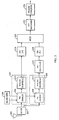
- FIG. 2 shows a preferred embodiment of the invention as used in a wireless base station (BTS).
- BTS wireless base station
- Data to be transmitted to the subscriber station is input first to a frame formatter 100 .
- the data which is encapsulated in the frame formatter may be voice data, fax, packet data, or any other data capable of being represented by a digital bit stream.
- the frame formatter 100 is operationally coupled with a forward error correction (FEC) module 102 , which adds forward error correction codes to the data stream.
- FEC forward error correction
- the FEC module 102 may use any of several forward error correction techniques, including turbo-coding, convolutional coding, or other form of soft decision or block coding.
- demux 104 After FEC coding, the data is processed by a demultiplexor, or demux 104 , which is operationally connected to the FEC module 102 .
- Demux 104 distributes the error correction coded symbols into different groups, each of which is processed separately until transmission.
- FIG. 2 depicts the use of two groups, one skilled in the art will appreciate that demux 104 may distribute symbols into more than two groups without departing from the embodied invention.
- the method of demultiplexing the single symbol stream into two symbol streams includes simple alternation, in which all odd symbols are distributed into one, and all even symbols are distributed into the other.
- Each group of bits is then processed by an interleaver 106 and 108 , operably connected to the demux 104 .
- Each interleaver may utilize any of a number of interleaving techniques, such as block interleaving and bit reversal interleaving.
- the output of one interleaver 106 is sent to a transmit subsystem 126 , shown in the exemplary embodiment as including a Walsh spreader 112 , a PN spreader 116 , and a transmitter 122 .
- the output of interleaver 106 is sent to the Walsh spreader 112 , which is operably connected to the interleaver 106 .
- CDMA systems that include an orthogonal spreading followed by a PN spreading are described in detail in the aforementioned U.S. Patent No. 5,109,459 . It will be understood that, although described in the context of traditional Walsh codes, the present invention is applicable to other orthogonal channelization methods such as orthogonal variable length spreading functions of the proposed WCDMA standard and described in detail the aforementioned U.S. Patent No. 5,751,761 .
- the PN spreading can be performed using either a traditional quadrature PN spreading such as standardized in the IS-95 standard or using a complex PN spreading such as described in the proposed cdma2000 and WCDMA Third Generation standards and described in detail in the aforementioned copending U.S. Patent Application Serial No. 08/856,428 .
- Walsh channels In a CDMA system using orthogonal Walsh coding, the channels that are distinguished from each other by utilizing these Walsh codes are referred to as Walsh channels.
- Walsh channels One skilled in the art will appreciate that a system could include transmission subsystems using an alternate form of signal separation technique, such as FDMA or TDMA, without departing from the embodied invention.
- the unshuffled output of the first interleaver 106 is processed in a manner typical of many current CDMA systems.
- the signal proceeds to a Walsh spreader 112 , which is operably connected to the interleaver 106 , and then to a PN spreader 116 , which is operably connected to the Walsh spreader 112 .
- the Walsh spreader 112 serves to multiply each data bit coming from the interleaver 106 by a Walsh code W i , while the PN spreader provides superior autocorrelation properties that allows for the demodulation of multipath signals.
- the PN spread signal from PN spreader 116 is provided to transmitter 122 which amplifies, upconverts and filters the signal from transmission though antenna 4 on transmission channel 8 .
- the output of the second interleaver 108 is sent to a shuffler 110 , operationally connected to the interleaver 108 , which resequences the data output by the interleaver 108 .
- the output of the shuffler 110 is then sent to a second transmission subsystem 128 , again shown in an exemplary embodiment as including a Walsh spreader 114 , a PN spreader 118 , and a transmitter 124 .
- the output of the shuffler 110 is sent to the Walsh spreader 114 , which is operably connected to the shuffler 110 .
- the Walsh spreader 114 serves to multiply each data bit coming from the shuffler 110 by a Walsh code W j .
- the shuffler 110 operates by cyclically rotating each group of four sequential symbols abcd into a different sequence of bits cdab.
- Other shuffling functions such as reversing or flipping, may be used without departing from the embodied invention.
- additional shuffling functions may be utilized for each symbol group, in a system having more than two such groups.
- the goal of the shuffling process is to reduce the effects of correlated fading on transmission channels 8 and 10 .
- a fade simultaneously effecting transmission channels 8 and 10 will not erase consecutive symbols in the frame of symbols.
- forward error correction decoders such as trellis decoders and turbo decoders are much more effective in correcting errors that not consecutive than they are at correcting those that are.
- the output of the shuffler 110 is processed in much the same way as the unshuffled signal from the first interleaver 106 .
- the shuffled signal proceeds from the shuffler 110 to a Walsh spreader 114 , and then to a PN spreader 118 .
- both transmission subsystems 126 and 128 may share a single transmit antenna.
- the exemplary embodiment envisions three alternative methods of separation of the signals transmitted from antennas 4 and 6 .
- the signals transmitted from antennas 4 and 6 are transmitted on the same frequency and the separation of the signals is provided by spreading the signals prior to transmission using different Walsh functions.
- the signals transmitted from antennas 4 and 6 are transmitted on different carrier frequencies in which case the Walsh spreading operations performed by Walsh spreaders 112 and 114 may be either the same or different.
- the signals are distinguished from one another by introducing a delay prior to transmission using delay element 120 . Methods of time transmit diversity are described in detail in aforementioned U.S. Patent Nos. 5,280,472 , 5,513,176 and 5,533,011 .
- the signals transmitted from antennas 4 and 6 are on the same frequency and may or may not be spread using the same Walsh spreading function in Walsh Spreaders 112 and 114 .
- FIG. 3 shows a preferred embodiment of the invention as used in a CDMA wireless subscriber station.
- the signal is received through antenna 200 and processed by receiver 202 .
- the resultant signals are then processed by multiple demodulation subsystems 207 and 209 .
- Demodulation subsystem 207 demodulates the signal that has traversed transmission channel 8 .
- Deinterleaver 216 receives the demodulated signal output by the demodulation subsystem 207 and de-interleaves the signal.
- receiver 202 If the signal that has traversed transmission channel 8 is transmitted on the same frequency as the signal transmitted on transmission channel 10 , then receiver 202 amplifies, down converts and filters the signal using the same hardware. However, if the signals that traversed transmission channels 8 and 10 have been transmitted on different carrier frequencies, then the received signal will be downconverted using different mixing frequencies and the resultant signals from the different mixing operation will be provided to demodulation subsystem 207 and 209 .
- Demodulation subsystem 209 demodulates the signal that has traversed transmission channel 10 .
- PN demodulator 206 demodulates the received signal in accordance with a PN offset that is determined in accordance with a signal from searcher 204 .
- the implementation of CDMA searchers is well known in the art, an exemplary embodiment of which is described in detail in aforementioned U.S. Patent No. 5,764,687 .
- the PN despread signal is provided to Walsh despreader, which removes the Walsh covering from the PN despread signal.
- the signal produced by the demodulator subsystem 207 is provided to de-interleaver 216 , which de-interleaves the uncovered signal so as to undo the interleaving operation performed by interleaver 106 .
- the signal which traversed transmission channel 10 is demodulated in demodulation subsystem 209 , within which the received signal is processed using a PN demodulator 208 , and then despread using a Walsh despreader 212 .
- the output of the demodulation subsystem 209 is then processed by an operably connected deshuffler 214 .
- the deshuffler 214 performs the inverse function of the shuffler 110 .
- the deshuffled output of the deshuffler 214 is then sent to an operably connected deinterleaver 218 .
- the deinterleaver 218 performs the inverse function of the interleaver 108 .
- the output of the interleavers 216 and 218 are connected to a multiplexor or MUX 220 , which performs the reverse operation of the demux 104 to form a single data stream.
- the resulting single data stream is then processed by a FEC decoder 222 , which performs error correction according to the forward error correction code utilized by the FEC coder 102 .
- the FEC decoder may use any of several forward error correction techniques, including turbo-coding, convolutional coding, or other form of soft decision or block coding.
- the data output by the FEC decoder 222 is then processed by a frame checker 224 , which verifies the validity of the received frames, usually using a CRC.
Abstract
Description
- The current invention relates to wireless telecommunications. More particularly, the present invention relates to a novel and improved transmitter design for enhancing the reliability of communications in a wireless communications system.
- The use of code division multiple access (CDMA) modulation techniques is one of several techniques for facilitating communications in which a large number of system users are present. Other multiple access communication system techniques, such as time division multiple access (TDMA), frequency division multiple access (FDMA) and AM modulation schemes such as amplitude companded single sideband (ACSSB) are known in the art. However, the spread spectrum modulation technique of CDMA has significant advantages over these other modulation techniques for multiple access communication systems.
- The use of CDMA techniques in a multiple access communication system is disclosed in
U.S. Patent No. 4,901,307 , entitled "SPREAD SPECTRUM MULTIPLE ACCESS COMMUNICATION SYSTEM USING SATELLITE OR TERRESTRIAL REPEATERS", assigned to the assignee of the present invention and incorporated by reference herein. The use of CDMA techniques in a multiple access communication system is further disclosed inU.S. Patent No. 5,103,459 , entitled "SYSTEM AND METHOD FOR GENERATING SIGNAL WAVEFORMS IN A CDMA CELLULAR TELEPHONE SYSTEM", and inU.S. Patent No. 5,751,761 , entitled "SYSTEM AND METHOD FOR ORTHOGONAL SPREAD SPECTRUM SEQUENCE GENERATION IN VARIABLE DATA RATE SYSTEMS", both assigned to the assignee of the present invention and incorporated by reference herein. The use of CDMA searchers is disclosed inU.S. Patent No. 5,764,687 , entitled "MOBILE DEMODULATOR ARCHITECTURE FOR A SPREAD SPECTRUM MULTIPLE ACCESS COMMUNICATION SYSTEM", assigned to the assignee of the present invention and incorporated by reference herein. Code division multiple access communications systems have been standardized in the United States in Telecommunications Industry Association TIA/EIA/IS-95-A, entitled "MOBILE STATION-BASE STATION COMPATIBILITY STANDARD FOR DUAL-MODE WIDEBAND SPREAD SPECTRUM CELLULAR SYSTEM", hereafter referred to as IS-95 and incorporated by reference herein. - The CDMA waveform, by its inherent nature of being a wideband signal, offers a form of frequency diversity by spreading the signal energy over a wide bandwidth. Therefore, frequency selective fading affects only a small part of the CDMA signal bandwidth. Space or path diversity on the forward or reverse link is obtained by providing multiple signal paths through simultaneous links to or from a mobile user through two or more antennas, cell sectors or cell-sites. Furthermore, path diversity may be obtained by exploiting the multipath environment through spread spectrum processing by allowing a signal arriving with different propagation delays to be received and processed separately. Examples of the utilization of path diversity are illustrated in
U.S. Patent No. 5,101,501 entitled "SOFT HANDOFF IN A CDMA CELLULAR TELEPHONE SYSTEM", andU.S. Patent No. 5,109,390 entitled "DIVERSITY RECEIVER IN A CDMA CELLULAR TELEPHONE SYSTEM", both assigned to the assignee of the present invention and incorporated by reference herein. - In the CDMA demodulator structure used in some IS-95 systems, the PN chip interval defines the minimum separation two paths must have in order to be combined. Before the distinct paths can be demodulated, the relative arrival times (or offsets) of the paths in the received signal must first be determined. The demodulator performs this function by "searching" through a sequence of offsets and measuring the energy received at each offset. If the energy associated with a potential offset exceeds a certain threshold, a demodulation element, or "finger" may be assigned to that offset. The signal present at that path offset can then be summed with the contributions of other fingers at their respective offsets.
- A method and apparatus of finger assignment based on searcher and finger energy levels is disclosed in
U.S. Patent No. 5,490,165 , entitled "FINGER ASSIGNMENT IN A SYSTEM CAPABLE OF RECEIVING MULTIPLE SIGNALS", assigned to the assignee of the present invention and incorporated by reference herein. In the exemplary embodiment, the CDMA signals are transmitted in accordance with IS-95. An exemplary embodiment of the circuitry capable of demodulating IS-95 forward link signals is described in detail inU.S. Patent No. 5,764,687 , entitled "MOBILE DEMODULATOR ARCHITECTURE FOR A SPREAD SPECTRUM MULTIPLE ACCESS SYSTEM", assigned to the assignee of the present invention and incorporated by reference herein. An exemplary embodiment of the circuitry capable of demodulating IS-95 reverse link signals is described in detail inU.S. Patent No. 5,654,979 , entitled "CELL SITE DEMODULATOR ARCHITECTURE FOR A SPREAD SPECTRUM MULTIPLE ACCESS COMMUNICATION SYSTEM," assigned to the assignee of the present invention and incorporated by reference herein. - In the exemplary embodiment, the signals are complex PN spread as described in
U.S. Patent Application Serial No. 08/856,428 , entitled "REDUCED PEAK TO AVERAGE TRANSMIT POWER HIGH DATA RATE IN A CDMA WIRELESS COMMUNICATION SYSTEM," filed April 9, 1996, assigned to the assignee of the present invention and incorporated by reference herein, and in accordance with the following equations:

where PNI and PNQ are distinct PN spreading codes and I' and Q' are two channels being spread at the transmitter. - The International Telecommunications Union recently requested the submission of proposed methods for providing high rate data and high-quality speech services over wireless communication channels. A first of these proposals was issued by the Telecommunications Industry Association, entitled "The cdma2000 ITU-R RTT Candidate Submission". A second of these proposals was issued by the European Telecommunications Standards Institute (ETSI), entitled "The ETSI UMTS Terrestrial Radio Access (UTRA) ITU-R RTT Candidate Submission". And a third proposal was submitted by U.S. TG 8/1 entitled "The UWC-136 Candidate Submission" (referred to herein as EDGE). The contents of these submissions is public record and is well known in the art.
- In addition to the aforementioned properties, CDMA's broadband nature permits the demodulation of signals having traversed different propagation paths. In
U.S Patent Nos. 5,280,472 ,5,513,176 ,5,553,011 , assigned to the assignee of the present invention and incorporated by reference herein, the usage of multiple sets of distributed antennas is employed to deliberately provide multiple paths of propagation. In the just mentioned U.S. Patents, sets of antennas are fed by a common signal with only time delay processing to distinguish signals. The transmit output of the base station is fed to a string of antenna elements for example with a coaxial cable. The antenna elements connect to the cable using power splitters. The resulting signals, amplified and frequency converted as necessary, are fed to the antennas. The salient features of this distributed antenna concept are as follows: (1) simple and inexpensive dual antenna node design; (2) neighboring antennas have time delays inserted in feed structure so signals received and transmitted from neighboring antennas are distinguishable by PN temporal processing; (3) exploitation of direct sequence CDMA's ability to discriminate against multipath; and (4) creation of deliberate multipath that satisfies discrimination criteria. - Antenna transmit diversity as well as multi-carrier transmission are promising new technologies that improve transmission resistance to fading by offering space and/or frequency diversity. In the antenna transmit diversity case for example, the data to be transmitted is encoded into symbols, which are then distributed among the antennas and transmitted.
- Many techniques have been proposed for mitigating mutual interference between signals transmitted from the different antennas. Such techniques include delay transmit diversity, orthogonal transmit diversity (OTD), time switched transmit diversity (TSTD), time delayed transmit diversity (TDTD), and multi-carrier transmit diversity (MCTD). Each of these methods shares with the others a common goal of providing additional diversity in the transmitted signal through space, time, frequency or code space. These methods are known in the art and have been described in proposals to the International Telecommunications Union in response to their request for proposed Third Generation Wireless communication systems. Methods for introducing diversity into a transmitted signal are almost limitless by their very nature. Copending
U.S. Patent Application Serial No. 08/929,380 , entitled "Method and Apparatus for Transmitting and Receiving Data Multiplexed onto Multiple Code Channels, Frequencies and Base Stations", filed September 15, 1997, assigned to the assignee of the present invention and incorporated by reference herein, describes a matrix of methods for transmitting CDMA signals using multiple carriers and multiple code channels for introducing diversity into the transmitted signal. - In addition, the multi-carrier transmission, whether it uses antenna transmit diversity or not, must distribute the coded symbols among the different carriers, which is similar to distributing symbols among several antennas in an antenna transmit diversity system. One skilled in the art will appreciate that, in the case where a multi-carrier system uses a single transmit antenna, the channels utilizing the two carriers may still be thought of as independent transmission channels which may or may not suffer from correlated fading. Correlated fading is the phenomenon whereby each of the transmissions suffers degradation in a temporally correlated fashion.
- In a system utilizing interleaving in conjunction with transmit diversity, it is desirable to fully utilize the gain offered by both techniques, as well as to make sure that the interleaver also performs well when the transmission channels become correlated. For example, in a system utilizing two transmission channels, using either two transmit antennas or two carriers, correlated fading in both transmission channels may cause the loss of adjacent transmitted coded symbols. Decoders such as trellis decoders and turbo decoders are often more susceptible to the loss of several successive symbols than to the loss of the same number of symbols spread throughout the data stream. In order to reduce the probability of loss of adjacent encoded symbols, interleavers such as block interleavers and turbo coded interleavers are employed. However, these traditional interleaving methods provide less time diversity when employed by traditional means in systems employing transmission diversity. Thus, there is a need felt in the art for a method of decreasing the chances of losing successive symbols in a system which utilizes transmit diversity.
- The current invention enhances the performance of a system utilizing interleaving and transmit diversity by reordering the sequence of symbols transmitted along the different transmission channels. For example, in the case of a system using two transmission channels, the symbols being transmitted on one channel are shuffled with respect to the symbols transmitted through the other channel. This shuffling makes it less likely that successive symbols output by the interleaver are lost to correlated fading in the two transmission channels.
- Suppose a source frame F is composed of N coded symbols Si (1<i<N). Suppose also that these symbols Si are distributed over M transmitters (different carriers or antennas or beth). The current invention splits the symbols into M groups Gj (1<j<M), one for each transmitter. Then each of the groups, Gj, is interleaved independently.
- A problem which can occur if the interleavers and splitter are not chosen correctly, or even worse if they are all identical, is that the performance will be severely degraded when the signals from the different transmitters go through channels that are correlated.
- Consider the case where there are 2 transmitters that lead to 2 antennas to provide space diveristy in a transmitted signal. If the symbols are allocated for transmission such that odd symbols are provided for transmission through the first antenna and the even symbols are provided for transmission through the second antenna and wherein the symbols are interleaved subsequent to their provision to the respective antennas. If traditional interleaving strategies are used, correlated fading will severely deteriorate performance.
- The goal of the shuffle is to make sure that even if the different transmission paths from the different transmitters become correlated, the performance degradation is minor. One particularly efficient implementation of the shuffle that each shuffle cyclically rotates the symbols it receives. Here is an example:
- Shuffler j: cyclically rotate the symbols to be transmitted by transmitter j by (j-1)*N/M symbols. Thus, if N= 4, M=2 and G2 after interleaving is "abcd", then shuffler 2 would output "cdab", which is "abcd" that has been cyclically rotated by N/M=2 symbols. An alternative embodiment of a shuffler is a flip. This transforms "abcd" into "dcba".
- It will be understood by one skilled in the art that the shuffle operations, though presented as being subsequent to and separate from the traditional interleaving operation, in reality would probably be combined with interleaving, yielding a single operation in a real implementation.
- The features, objects, and advantages of the present invention will become more apparent from the detailed description set forth below when taken in conjunction with the drawings in which like reference characters identify correspondingly throughout and wherein:
- FIG. 1 is a diagram illustrating basic components of a wireless communication system incorporating an embodiment of the invention.
- FIG. 2 is a block diagram of a preferred embodiment of the invention in a wireless base station.
- FIG. 3 is a block diagram of a preferred embodiment of the invention in a wireless subscriber station.
- FIG. 1 shows the present invention in the context of a wireless communication system. The base station transceiver subsystem (BTS) 2 includes two transmit antennas 4 and 6, which are used to transmit signals along two
transmission channels 8 and 10 to asubscriber station 12. The present invention is applicable to any communication system employing diversity transmission. In the exemplary embodiment, the signals transmitted from base station transceiver subsystem (BTS) 2 are code division multiple access communication signals. One skilled in the art will appreciate that the BTS could be replaced by a wireless local loop concentrated subscriber station (CSS) or any other transmitter employing diversity transmission without departing from the embodied invention. The generation and transmission of code division multiple access communication signals is well known in the art and is described in detail in the aforementionedU.S. Patent No. 5,103,459 and in the IS-95 specification. The present invention is also applicable to frequency division multiple access (FDMA) communication systems and to time division multiple access (TDMA) communication systems, such the GSM communication system and the proposed third generation TDMA communication system commonly referred to as EDGE. - The transmit antennas 4 and 6, could be separated spatially to provide transmit diversity by either placing them in different physical locations, or by using directional antennas pointed in different directions from each other. In an alternate embodiment using multicarrier transmit diversity, a single antenna could be used as the source of the two signals.
- The
subscriber station 12 is shown as a car, but could also be a wireless modem, wireless local loop subscriber station, or any other portable wireless communication subscriber equipment. The method and apparatus for simultaneously receiving multiple transmissions is well known in the art. In the exemplary embodiment, the signals transmitted from antennas 4 and 6 are received atsubscriber station 12 using a RAKE receiver, the implementation of which is well known in the art and is described in the aforementionedU.S. Patent No. 5,109,390 . - FIG. 2 shows a preferred embodiment of the invention as used in a wireless base station (BTS). Data to be transmitted to the subscriber station is input first to a
frame formatter 100. The data which is encapsulated in the frame formatter may be voice data, fax, packet data, or any other data capable of being represented by a digital bit stream. - The
frame formatter 100 is operationally coupled with a forward error correction (FEC)module 102, which adds forward error correction codes to the data stream. TheFEC module 102 may use any of several forward error correction techniques, including turbo-coding, convolutional coding, or other form of soft decision or block coding. - After FEC coding, the data is processed by a demultiplexor, or
demux 104, which is operationally connected to theFEC module 102.Demux 104 distributes the error correction coded symbols into different groups, each of which is processed separately until transmission. Though FIG. 2 depicts the use of two groups, one skilled in the art will appreciate thatdemux 104 may distribute symbols into more than two groups without departing from the embodied invention. In the exemplary embodiment, the method of demultiplexing the single symbol stream into two symbol streams includes simple alternation, in which all odd symbols are distributed into one, and all even symbols are distributed into the other. - Each group of bits is then processed by an
interleaver demux 104. Each interleaver may utilize any of a number of interleaving techniques, such as block interleaving and bit reversal interleaving. The output of oneinterleaver 106 is sent to a transmitsubsystem 126, shown in the exemplary embodiment as including aWalsh spreader 112, aPN spreader 116, and atransmitter 122. The output ofinterleaver 106 is sent to theWalsh spreader 112, which is operably connected to theinterleaver 106. - CDMA systems that include an orthogonal spreading followed by a PN spreading are described in detail in the aforementioned
U.S. Patent No. 5,109,459 . It will be understood that, although described in the context of traditional Walsh codes, the present invention is applicable to other orthogonal channelization methods such as orthogonal variable length spreading functions of the proposed WCDMA standard and described in detail the aforementionedU.S. Patent No. 5,751,761 . In the exemplary embodiment, the PN spreading can be performed using either a traditional quadrature PN spreading such as standardized in the IS-95 standard or using a complex PN spreading such as described in the proposed cdma2000 and WCDMA Third Generation standards and described in detail in the aforementioned copendingU.S. Patent Application Serial No. 08/856,428 . - In a CDMA system using orthogonal Walsh coding, the channels that are distinguished from each other by utilizing these Walsh codes are referred to as Walsh channels. One skilled in the art will appreciate that a system could include transmission subsystems using an alternate form of signal separation technique, such as FDMA or TDMA, without departing from the embodied invention.
- As shown, the unshuffled output of the
first interleaver 106 is processed in a manner typical of many current CDMA systems. The signal proceeds to aWalsh spreader 112, which is operably connected to theinterleaver 106, and then to aPN spreader 116, which is operably connected to theWalsh spreader 112. TheWalsh spreader 112 serves to multiply each data bit coming from theinterleaver 106 by a Walsh code Wi, while the PN spreader provides superior autocorrelation properties that allows for the demodulation of multipath signals. The PN spread signal fromPN spreader 116 is provided totransmitter 122 which amplifies, upconverts and filters the signal from transmission though antenna 4 on transmission channel 8. - The output of the
second interleaver 108 is sent to ashuffler 110, operationally connected to theinterleaver 108, which resequences the data output by theinterleaver 108. The output of theshuffler 110 is then sent to asecond transmission subsystem 128, again shown in an exemplary embodiment as including aWalsh spreader 114, aPN spreader 118, and atransmitter 124. The output of theshuffler 110 is sent to theWalsh spreader 114, which is operably connected to theshuffler 110. TheWalsh spreader 114 serves to multiply each data bit coming from theshuffler 110 by a Walsh code Wj. - In a preferred embodiment of the invention, the
shuffler 110 operates by cyclically rotating each group of four sequential symbols abcd into a different sequence of bits cdab. Other shuffling functions, such as reversing or flipping, may be used without departing from the embodied invention. One skilled in the art will appreciate that additional shuffling functions may be utilized for each symbol group, in a system having more than two such groups. The goal of the shuffling process is to reduce the effects of correlated fading ontransmission channels 8 and 10. By employingshuffler 110, a fade simultaneously effectingtransmission channels 8 and 10 will not erase consecutive symbols in the frame of symbols. As is well known in the art, forward error correction decoders such as trellis decoders and turbo decoders are much more effective in correcting errors that not consecutive than they are at correcting those that are. - The output of the
shuffler 110 is processed in much the same way as the unshuffled signal from thefirst interleaver 106. The shuffled signal proceeds from theshuffler 110 to aWalsh spreader 114, and then to aPN spreader 118. - In an alternative embodiment of the invention using multiple carriers to accomplish transmit diversity, both
transmission subsystems - The exemplary embodiment envisions three alternative methods of separation of the signals transmitted from antennas 4 and 6. In the first embodiment, the signals transmitted from antennas 4 and 6 are transmitted on the same frequency and the separation of the signals is provided by spreading the signals prior to transmission using different Walsh functions. In the second exemplary embodiment, the signals transmitted from antennas 4 and 6 are transmitted on different carrier frequencies in which case the Walsh spreading operations performed by
Walsh spreaders delay element 120. Methods of time transmit diversity are described in detail in aforementionedU.S. Patent Nos. 5,280,472 ,5,513,176 and5,533,011 . In this alternative embodiment, the signals transmitted from antennas 4 and 6 are on the same frequency and may or may not be spread using the same Walsh spreading function inWalsh Spreaders - FIG. 3 shows a preferred embodiment of the invention as used in a CDMA wireless subscriber station. The signal is received through
antenna 200 and processed byreceiver 202. The resultant signals are then processed bymultiple demodulation subsystems Demodulation subsystem 207 demodulates the signal that has traversed transmission channel 8.Deinterleaver 216 receives the demodulated signal output by thedemodulation subsystem 207 and de-interleaves the signal. - If the signal that has traversed transmission channel 8 is transmitted on the same frequency as the signal transmitted on
transmission channel 10, thenreceiver 202 amplifies, down converts and filters the signal using the same hardware. However, if the signals that traversedtransmission channels 8 and 10 have been transmitted on different carrier frequencies, then the received signal will be downconverted using different mixing frequencies and the resultant signals from the different mixing operation will be provided todemodulation subsystem -
Demodulation subsystem 209 demodulates the signal that has traversedtransmission channel 10. Withindemodulator 207, PN demodulator 206 demodulates the received signal in accordance with a PN offset that is determined in accordance with a signal fromsearcher 204. The implementation of CDMA searchers is well known in the art, an exemplary embodiment of which is described in detail in aforementionedU.S. Patent No. 5,764,687 . - The PN despread signal is provided to Walsh despreader, which removes the Walsh covering from the PN despread signal. The signal produced by the
demodulator subsystem 207 is provided tode-interleaver 216, which de-interleaves the uncovered signal so as to undo the interleaving operation performed byinterleaver 106. - The signal which traversed
transmission channel 10 is demodulated indemodulation subsystem 209, within which the received signal is processed using aPN demodulator 208, and then despread using a Walsh despreader 212. The output of thedemodulation subsystem 209 is then processed by an operably connecteddeshuffler 214. Thedeshuffler 214 performs the inverse function of theshuffler 110. The deshuffled output of thedeshuffler 214 is then sent to an operably connecteddeinterleaver 218. Thedeinterleaver 218 performs the inverse function of theinterleaver 108. - The output of the
interleavers MUX 220, which performs the reverse operation of thedemux 104 to form a single data stream. The resulting single data stream is then processed by aFEC decoder 222, which performs error correction according to the forward error correction code utilized by theFEC coder 102. As with the FEC coder, the FEC decoder may use any of several forward error correction techniques, including turbo-coding, convolutional coding, or other form of soft decision or block coding. - The data output by the
FEC decoder 222 is then processed by aframe checker 224, which verifies the validity of the received frames, usually using a CRC. - The following numbered paragraphs define alternative embodiments of the invention.
- 1. An apparatus for transmitting an information signal, comprising:
- first interleaver means for receiving a first portion of said information signal and for reordering the symbols of said first portion of said information signal in accordance with a first interleaving format to provide a first interleaved signal;
- first transmission subsystem for receiving said first interleaved signal and for transmitting said first interleaved signal on a first transmission channel;
- second interleaver means for receiving a second portion of said information signal and reordering the symbols of said second portion of said information signal in accordance with a second interleaving format to provide a second interleaved signal; and
- second transmission subsystem for receiving said second interleaved signal and for transmitting said second interleaved signal on a second transmission channel.
- 2. The apparatus of paragraph 1 further comprising a demultiplexer for receiving said information signal and dividing said information signal into said first portion and said second portion, and providing said first portion to said first interleaver and providing said second portion to said second interleaver.
- 3. The apparatus of
paragraph 2 wherein said demultiplexer divides up said information signal by placing each odd symbol into said first portion and placing each even symbol into said second portion. - 4. The apparatus of
paragraph 2 further comprising a forward error correction module for receiving a set of bits and for encoding in accordance with a predetermined forward error correction format to provide said information signal. - 5. The apparatus of paragraph 4 wherein said forward error correction format may be a convolutional encoding format.
- 6. The apparatus of paragraph 4 wherein said forward error correction format may be a turbo coding format.
- 7. The apparatus of paragraph 1 wherein said first interleaving format and said second interleaving format may be block interleaving formats.
- 8. The apparatus of paragraph 1 wherein said first interleaving format and said second interleaving format may be bit reversal interleaving formats.
- 9. The apparatus of paragraph 1 wherein said first interleaving format may be a block interleaving format and said second interleaving format may be a bit reversal interleaving format.
- 10. The apparatus of paragraph 1 wherein said first interleaving format and said second interleaving format may be the same.
- 11. The apparatus of paragraph 1 further comprising a shuffler for receiving said second interleaved signal and shuffling the symbols from said second interleaved signal before transmission through said second transmission subsystem.
- 12. The apparatus of paragraph 1 wherein said second interleaver comprises:
- interleaver subsystem for reordering symbols in accordance with a predetermined interleaver format to provide a pre-shuffled signal; and
- shuffler for receiving said pre-shuffled signal and shuffling the symbols from said pre-shuffled signal to produce said second interleaved signal.
- 13. The apparatus of paragraph 11 wherein said shuffler performs shuffling by cyclically rotating sets of a predetermined number of symbols.
- 14. The apparatus of paragraph 13 wherein said predetermined number is four.
- 15. The apparatus of paragraph 14 wherein said shuffler rotates said sets of four symbols by two symbols.
- 16. The apparatus of paragraph 11 wherein said shuffler performs shuffling by flipping sets of a predetermined number of symbols.
- 17. The apparatus of paragraph 16 wherein said predetermined number is four.
- 18. The apparatus of paragraph 1 wherein said first transmission subsystem transmits said first interleaved signal on a first transmission channel by spreading said first interleaved signal in accordance with a first Walsh function to produce a first Walsh coded signal; and
wherein said second transmission subsystem transmits said second interleaved signal on a second transmission channel by spreading said second interleaved signal in accordance with a second Walsh function to produce a second Walsh coded signal. - 19. The apparatus of paragraph 18 wherein said first Walsh function is the same as said second Walsh function.
- 20. The apparatus of paragraph 18 wherein said first Walsh function is orthogonal to said second Walsh function.
- 21. The apparatus of paragraph 20 wherein said first transmission subsystem and said second transmission subsystem are synchronized in time and phase.
- 22. The apparatus of paragraph 18 wherein said first transmission subsystem further comprises a first PN spreader for receiving said first Walsh coded signal and spreading said first Walsh coded signal in accordance with a first pseudonoise (PN) function to provide a first PN spread signal, and said second transmission subsystem further comprises a second PN spreader for receiving said second Walsh coded signal and spreading said second Walsh coded signal in accordance with a second pseudonoise (PN) function to provide a second PN spread signal.
- 23. The apparatus of paragraph 22 wherein said first PN spreader and said second PN spreader utilize quadrature PN spreading.
- 24. The apparatus of paragraph 22 wherein said first PN spreader and said second PN spreader utilize complex PN spreading.
- 25. The apparatus of paragraph 22 wherein said second transmission subsystem further comprises a delay element for receiving said second PN spread signal and producing a delayed PN spread signal.
- 26. The apparatus of paragraph 25 wherein said first transmission subsystem further comprises a first transmitter for upconverting to a first frequency and amplifying said first PN spread signal and producing a first transmission signal, and said second transmission subsystem further comprises a second transmitter for upconverting to a second frequency and amplifying said delayed PN spread signal and producing a second transmission signal.
- 27. The apparatus of paragraph 26 wherein said first transmitter transmits said first transmission signal through an antenna and said second transmitter said second transmission signal through said antenna.
- 28. The apparatus of paragraph 26 wherein said first transmitter transmits said first transmission signal through a first antenna and said second transmitter said second transmission signal through a second antenna.
- 29. The apparatus of paragraph 28 wherein said first frequency is equal to said second frequency.
- 30. The apparatus of paragraph 28 wherein said first frequency is greater than said second frequency.
- 31. The apparatus of paragraph 22 wherein said first transmission subsystem further comprises a first transmitter for upconverting to a first frequency and amplifying said first PN spread signal and producing a first transmission signal; and
said second transmission subsystem further comprises a second transmitter for upconverting to a second frequency and amplifying said second PN spread signal and producing a second transmission signal. - 32. The apparatus of paragraph 31 wherein said first transmitter transmits said first transmission signal through a first antenna and said second transmitter said second transmission signal through a second antenna.
- 33. The apparatus of paragraph 32 wherein said first frequency is equal to said second frequency.
- 34. The apparatus of paragraph 32 wherein said first frequency is greater than said second frequency.
- 35. The apparatus of paragraph 31 wherein said first transmitter transmits said first transmission signal through an antenna and said second transmitter said second transmission signal through said antenna.
- 36. An apparatus for receiving an information signal comprising:
- first demodulation subsystem for receiving a first portion of a received signal, demodulating said first portion to create a first demodulated signal;
- first deinterleaver for deinterleaving said first demodulated signal according to a first deinterleaving format to produce a first deinterleaved signal;
- second demodulation subsystem for receiving a second portion of a received signal, demodulating said second portion to create a second demodulated signal; and
- second deinterleaver for deinterleaving said second demodulated signal according to a second deinterleaving format to produce a second deinterleaved signal.
- 37. The apparatus of paragraph 36 further comprising a multiplexor for receiving said first deinterleaved signal and said second deinterleaved signal and combining them to create a multiplexed signal.
- 38. The apparatus of paragraph 37 wherein said multiplexor produces the stream of symbols contained in said multiplexed signal by alternating symbols received in said first deinterleaved signal and said second deinterleaved signal, wherein all odd symbols of said demultiplexed signal are extracted from said first deinterleaved signal, and all even symbols are extracted from said second deinterleaved signal.
- 39. The apparatus of paragraph 37 further comprising a forward error correction decoder for receiving said demultiplexed signal and decoding said demultiplexed signal in accordance with a predetermined forward error correction format to extract an information signal from said demultiplexed signal.
- 40. The apparatus of paragraph 39 wherein said forward error correction decoder may be a turbo decoder.
- 41. The apparatus of paragraph 39 wherein said forward error correction decoder may be a trellis decoder.
- 42. The apparatus of paragraph 39 wherein said forward error correction decoder may be a soft decision decoder.
- 43. The apparatus of paragraph 39 wherein said forward error correction decoder may be a block decoder.
- 44. The apparatus of paragraph 37 wherein said first deinterleaver and said second deinterleaver may be block deinterleavers.
- 45. The apparatus of paragraph 37 wherein said first deinterleaver and said second deinterleaver may be bit reversal deinterleavers.
- 46. The apparatus of paragraph 37 wherein said first deinterleaver may be a block deinterleaver and said second deinterleaver may be a bit reversal deinterleaver.
- 47. The apparatus of paragraph 37 wherein said first deinterleaving format may be the same as said second deinterleaving format.
- 48. The apparatus of paragraph 37 further comprising a deshuffler, operably connected between said second demodulation subsystem and said second deinterleaver, for receiving said second demodulated signal and unshuffling said second demodulated signal to produce an unshuffled signal used by said second deinterleaver.
- 49. The apparatus of paragraph 37 wherein said second deinterleaver further comprises a deshuffler for unshuffling said second demodulated signal prior to performing said deinterleaving.
- 50. The apparatus of paragraph 48 wherein said deshuffler performs deshuffling by cyclically rotating sets of a predetermined number of symbols.
- 51. The apparatus of paragraph 50 wherein said predetermined number may be four.
- 52. The apparatus of paragraph 51 wherein said deshuffler rotates said sets of four symbols by two symbols.
- 53. The apparatus of paragraph 48 wherein said deshuffler performs deshuffling by flipping sets of a predetermined number of symbols.
- 54. The apparatus of paragraph 53 wherein said predetermined number may be four.
- 55. The apparatus of paragraph 36 wherein said first demodulation subsystem further comprises a first PN despreader for receiving said first portion of said received signal and despreading said first portion of said received signal in accordance with a first pseudonoise (PN) sequence to produce a first PN despread signal; and
wherein said second demodulation subsystem further comprises a second PN despreader for receiving said second portion of said received signal and despreading said second portion of said received signal in accordance with a second PN sequence to produce a second PN despread signal. - 56. The apparatus of paragraph 55 wherein said first PN despreader and said second PN despreader may be quadrature PN despreaders.
- 57. The apparatus of paragraph 55 wherein said first PN despreader and said second PN despreader may be complex PN despreaders.
- 58. The apparatus of paragraph 55 further comprising a searcher for providing time offsets used for PN despreading by said PN despreaders.
- 59. The apparatus of paragraph 55 wherein said first demodulation subsystem further comprises a first Walsh despreader for receiving said first PN despread signal and despreading said first PN despread signal in accordance with a first Walsh function to produce a first Walsh decoded signal; and
wherein said second transmission subsystem further comprises a second Walsh despreader for receiving said second PN despread signal and despreading said second PN despread signal in accordance with a second Walsh function to produce a second Walsh decoded signal. - 60. The apparatus of paragraph 59 wherein said first Walsh function and said second Walsh function may be the same as each other.
- 61. The apparatus of paragraph 59 wherein said first Walsh function may be orthogonal to second Walsh function.
- 62. The apparatus of paragraph 36 wherein said first demodulation subsystem further comprises a first receiver subsystem for amplifying and downconverting from a first frequency a received signal to produce said first portion of a received signal, and
wherein said second demodulation subsystem further comprises a second receiver subsystem for amplifying and downconverting from a second frequency said received signal to produce said second portion of a received signal. - 63. The apparatus of paragraph 62 wherein said first frequency may be equal to said second frequency.
- 64. The apparatus of paragraph 63 wherein said first demodulation subsystem and said second demodulation subsystem share a single receiver subsystem.
- 65. The apparatus of paragraph 62 wherein said first frequency is greater than said second frequency.
Claims (39)
- An apparatus for a communication system, comprising:a demultiplexer for distributing transmit data symbols into a plurality of streams of data symbols;a plurality of interleavers for interleaving said plurality of streams of data symbols;a shuffler for cyclically rotating output of at least one of said plurality of interleavers.
- The apparatus as recited in claim 1 further comprising:a transmission system for Walsh covering and modulating outputs of said plurality of interteavers, excluding said at least one of said plurality of interleavers, and said shuffler for transmission of said data symbols over at least a plurality of carrier frequencies.
- The apparatus as recited in claim 1 further comprising:an encoder for encoding information data bits for producing said transmit data symbols.
- A method for a communication system, comprising:demultiplexing transmit data symbols into a plurality of streams of data symbols;interleaving data symbols of each stream of said plurality of streams of data symbols for producing of a plurality of interleaved data streams;cyclically rotating data symbols of at least one of said plurality of interleaved data streams for producing at least one stream of data symbols with cyclically rotated data symbols.
- The method as recited in claim 4 further comprising:Walsh covering and modulating said plurality of interleaved data streams, excluding said at least one of the plurality of interleaved data streams, and the at least one stream of data symbols with cyclically rotated data symbols for transmission of said data symbols over at least a plurality of carrier frequencies.
- The method as recited in claim 4 further comprising:encoding information data bits for producing said transmit data symbols.
- An apparatus for a communication system, comprising:a de-shuffler for cyclically de-rotating at least of one of a plurality of streams of data symbols for producing at least one of cyclically de-rotated streams of data symbols;a plurality of de-interleavers for de-interleaving said plurality of streams of data symbols, excluding said at least one of said plurality of streams of data symbols, and said at least one of cyclically de-rotated streams of data symbols for producing a plurality of de-interleaved data streams;multiplexer for multiplexing said plurality of de-interleaved data streams for producing receive data symbols.
- The apparatus as recited in claim 7 further comprising:a receive system for Walsh de-covering and demodulating received signals over at least a plurality of carrier frequencies for producing said plurality of streams of data symbols.
- The apparatus as recited in claim 7 further comprising:a decoder for said receive data symbols for producing received information data.
- A method for a communication system, comprising:cyclically de-rotating at least of one of a plurality of streams of data symbols for producing at least one of cyclically de-rotated streams of data symbols;de-interleaving said plurality of streams of data symbols, excluding said at least one of said plurality of streams of data symbols, and said at least one of cyclically de-rotated streams of data symbols for producing a plurality of de-interleaved data streams;multiplexing said plurality of de-interleaved data streams for producing receive data symbols.
- A method as recited in claim 10 further comprising:Walsh de-covering and demodulating received signals over at least a plurality of carrier frequencies for producing said plurality of streams of data symbols.
- A method as recited in claim 10 further comprising:decoding said receive data symbols for producing received information data.
- An apparatus for transmitting an information signal, comprising:first interleaver means for receiving a first portion of said information signal and for reordering the symbols of said first portion of said information signal in accordance with a first interleavinig format to provide a first interleaved signal;a first transmission subsystem for receiving said first interleaved signal and for transmitting said first interleaved signal on a first transmission channel;a second interleaver means for receiving a second portion of said information signal and reordering the symbols of said second portion of said information signal in accordance with a second interleaving format to provide a second interleaved signal; anda second transmission subsystem for receiving said second interleaved signal and for transmitting said second interleaved signal on a second transmission channel.
- The apparatus of claim 13 further comprising a demultiplexer for receiving said information signal and dividing said information signal into said first portion and said second portion, and providing said first portion to said first interleaver and providing said second portion to said second interleaver.
- The apparatus of claim 13 wherein said demultiplexer divides up said information signal by placing each odd symbol into said first portion and placing each even symbol into said second portion.
- The apparatus of claim 13 wherein said first interleaving format and said second interleaving format are block interleaving formats.
- The apparatus of claim 13 wherein said first interleaving format and said second interleaving format are bit reversal interleaving.
- The apparatus of claim 13 wherein said first interleaving format is a block interleaving format and said second interleaving format is a bit reversal interleaving format.
- The apparatus of claim 13 wherein said first interleaving format and said second interleaving format are the same.
- The apparatus of claim 13 further comprising a shuffler for receiving said second interleaved signal and snuffling the symbols from said second interleaved signal before transmission through said second transmission subsystem.
- The apparatus of claim 13 wherein said second interleaver comprises:interleaver subsystem for reordering symbols in accordance with a predetermined interleaver format to provide a pre-shuflled signal; anda shuffler for receiving said pre-shuffled signal and shuffling the symbols from said pre-shuffled to produce said second interleaved signal.
- The apparatus of claim 13 wherein said shuffler performs shuffling by cyclically rotating sets of a predetermined number of symbols.
- The apparatus of claim 13 wherein said first transmission subsystem transmits said first interleaved signal on a first transmission channel by spreading said first interleaved signal in accordance with a first Walsh function to produce a first Walsh coded signal; and
wherein said second transmission subsystem transmits said second interleaved signal on a second transmission channel by spreading said second interleaved signal in accordance with a second Walsh function to produce a second Walsh coded signal. - The apparatus of claim 13 wherein said first Walsh function is the same as said second Walsh function.
- The apparatus of claim 13 wherein said first Walsh function is orthogonal to said second Walsh function.
- The apparatus of claim 1 wherein said first transmission subsystem and said second transmission subsystem are synchronized in time and phase.
- The apparatus of claim 13 wherein said first transmission subsystem further comprises a first PN spreader for receiving said first Walsh coded signal and spreading said first Walsh coded signal in accordance with a first pseudonoise (PN) function to provide a first PN spread signal, and said second transmission subsystem further comprises a second PN spreader for receiving said second Walsh coded signal and spreading said second Walsh coded signal in accordance with a second pseudonoise (PN) function to provide a second PN spread signal.
- The apparatus of claim 13 wherein said first PN spreader and said second PN spreader utilize quadrature PN spreading.
- The apparatus of claim 13 wherein said first PN spreader and said second PN spreader utilize complex PN spreading.
- The apparatus of claim 13 wherein said second transmission subsystem further comprises a delay element for receiving said second PN spread signal and producing a delayed PN spread signal.
- The apparatus of claim 13 wherein said first transmission subsystem further comprises a first transmitter for upconverting to a first frequency and amplifying said first PN spread signal and producing a first transmission signal, and said second transmission subsystem further comprises a second transmitter for converting to a second frequency and amplifying said delayed PN spread signal and producing a second transmission signal.
- An apparatus for receiving an information signal, comprising:a first demodulation subsystem for receiving a first portion of a received signal, demodulating said first portion to create a first demodulated signal;first deinterleaver for deinterleaving said first demodulated signal according to a first deinterleaving format to produce a first deinterleaved signal;a second demodulation subsystem for receiving a second portion of a received signal, demodulating said second portion to create a second demodulated signal; anda second deinterleaver for deinterleaving said second demodulated signal according to a second deinterleaving format to produce a second deinterleaved signal.
- The apparatus of claim 32 further comprising a multiplexor for receiving said first deinterleaved signal and said second deinterleaved signal and combining them to create a multiplexed signal.
- The apparatus of claim 32 wherein said multiplexor produces the stream of symbols contained in said multiplexed signal by alternating symbols received in said first deinterleaved signal and said second deinterleaved signal, wherein all odd symbols of said demultiplexed signal are extracted from said first deinterleaved signal, and all even symbols are extracted from said second deinterleaved signal.
- The apparatus of claim 32 further comprising a forward error correction decoder for receiving said demultiplexed signal and decoding said demultiplexed signal in accordance with a predetermined forward error correction format to extract an information signal from said demultiplexed signal.
- The apparatus of claim 32 further comprising a deshuffler, operably connected between said second demodulation subsystem and said second deinterleaver, for receiving said second demodulated signal and unshuffling said second demodulated signal to produce an unshuffled signal used by said second deinterleaver.
- The apparatus of claim 32 wherein said second deinterleaver further comprises a deshuffler for unshuffling said second demodulated signal prior to performing said deinterleaving.
- The apparatus of claim 32 wherein said first demodulation subsystem further comprises a first PN despreader for receiving said first portion of said received signal and despreading said first portion of said received signal in accordance with a first pseudonoise (PN) sequence to produce a first PN despread signal; and
wherein said second demodulation subsystem further comprises a second PN despreader for receiving said second portion of said received signal and despreading said second portion of said received signal in accordance with a second PN sequence to produce a second PN despread signal. - The apparatus of claim 32 wherein said first demodulation subsystem further comprises a first Walsh despreader for receiving said first PN despread signal and despreading said first PN despread signal in accordance with a first Walsh function to produce a first Walsh decoded signal; and
wherein said second transmission subsystem further comprises a second Walsh despreader for receiving said second PN despread signal and despreading said second PN despread signal in accordance with a second Walsh function to produce a second Walsh decoded signal.
Priority Applications (2)
| Application Number | Priority Date | Filing Date | Title |
|---|---|---|---|
| DK10180165.2T DK2293463T3 (en) | 1999-04-15 | 2000-04-12 | INTERLEAVER AND DEINTERLEAVER FOR USE IN A MULTIPLE TRANSMISSION COMMUNICATION SYSTEM |
| EP10180165.2A EP2293463B1 (en) | 1999-04-15 | 2000-04-12 | Interleaver and deinterleaver for use in a diversity transmission communication system |
Applications Claiming Priority (2)
| Application Number | Priority Date | Filing Date | Title |
|---|---|---|---|
| US09/293,527 US6356528B1 (en) | 1999-04-15 | 1999-04-15 | Interleaver and deinterleaver for use in a diversity transmission communication system |
| EP00922120A EP1169790B1 (en) | 1999-04-15 | 2000-04-12 | Interleaver and deinterleaver for use in a diversity transmission communication system |
Related Parent Applications (2)
| Application Number | Title | Priority Date | Filing Date |
|---|---|---|---|
| EP00922120.1 Division | 2000-04-12 | ||
| EP00922120A Division EP1169790B1 (en) | 1999-04-15 | 2000-04-12 | Interleaver and deinterleaver for use in a diversity transmission communication system |
Related Child Applications (2)
| Application Number | Title | Priority Date | Filing Date |
|---|---|---|---|
| EP10180165.2A Division EP2293463B1 (en) | 1999-04-15 | 2000-04-12 | Interleaver and deinterleaver for use in a diversity transmission communication system |
| EP10180165.2 Division-Into | 2010-09-27 |
Publications (3)
| Publication Number | Publication Date |
|---|---|
| EP1855392A2 true EP1855392A2 (en) | 2007-11-14 |
| EP1855392A3 EP1855392A3 (en) | 2007-12-26 |
| EP1855392B1 EP1855392B1 (en) | 2013-10-09 |
Family
ID=23129443
Family Applications (3)
| Application Number | Title | Priority Date | Filing Date |
|---|---|---|---|
| EP10180165.2A Expired - Lifetime EP2293463B1 (en) | 1999-04-15 | 2000-04-12 | Interleaver and deinterleaver for use in a diversity transmission communication system |
| EP07014757.4A Expired - Lifetime EP1855392B1 (en) | 1999-04-15 | 2000-04-12 | Interleaver and deinterleaver for use in a diversity transmission communication system |
| EP00922120A Expired - Lifetime EP1169790B1 (en) | 1999-04-15 | 2000-04-12 | Interleaver and deinterleaver for use in a diversity transmission communication system |
Family Applications Before (1)
| Application Number | Title | Priority Date | Filing Date |
|---|---|---|---|
| EP10180165.2A Expired - Lifetime EP2293463B1 (en) | 1999-04-15 | 2000-04-12 | Interleaver and deinterleaver for use in a diversity transmission communication system |
Family Applications After (1)
| Application Number | Title | Priority Date | Filing Date |
|---|---|---|---|
| EP00922120A Expired - Lifetime EP1169790B1 (en) | 1999-04-15 | 2000-04-12 | Interleaver and deinterleaver for use in a diversity transmission communication system |
Country Status (20)
| Country | Link |
|---|---|
| US (3) | US6356528B1 (en) |
| EP (3) | EP2293463B1 (en) |
| JP (1) | JP4574866B2 (en) |
| KR (2) | KR100793654B1 (en) |
| CN (1) | CN1178408C (en) |
| AT (1) | ATE371304T1 (en) |
| AU (1) | AU774761B2 (en) |
| BR (1) | BR0009766B1 (en) |
| CA (1) | CA2369959C (en) |
| DE (1) | DE60036099T2 (en) |
| DK (1) | DK2293463T3 (en) |
| ES (2) | ES2649368T3 (en) |
| HK (1) | HK1042997B (en) |
| IL (3) | IL145694A0 (en) |
| MX (1) | MXPA01010401A (en) |
| NO (1) | NO325476B1 (en) |
| PT (1) | PT2293463T (en) |
| RU (1) | RU2252484C2 (en) |
| UA (1) | UA66408C2 (en) |
| WO (1) | WO2000064073A1 (en) |
Families Citing this family (61)
| Publication number | Priority date | Publication date | Assignee | Title |
|---|---|---|---|---|
| US6356528B1 (en) * | 1999-04-15 | 2002-03-12 | Qualcomm Incorporated | Interleaver and deinterleaver for use in a diversity transmission communication system |
| US6668352B1 (en) * | 1999-04-28 | 2003-12-23 | Samsung Electronics Co., Ltd. | Distortion compensating device and method in a multi-code mobile communication system |
| US6594473B1 (en) * | 1999-05-28 | 2003-07-15 | Texas Instruments Incorporated | Wireless system with transmitter having multiple transmit antennas and combining open loop and closed loop transmit diversities |
| US6721339B2 (en) * | 1999-08-17 | 2004-04-13 | Lucent Technologies Inc. | Method of providing downlink transmit diversity |
| US6728296B1 (en) * | 1999-10-19 | 2004-04-27 | Skyworks Solutions, Inc. | Direct sequence spread spectrum system with enhanced forward error correction code feature |
| US6661833B1 (en) * | 2000-01-31 | 2003-12-09 | Qualcomm Incorporated | PN generators for spread spectrum communications systems |
| GB0004121D0 (en) * | 2000-02-23 | 2000-04-12 | Koninkl Philips Electronics Nv | Communication system and a transmitter for use in the system |
| GB0004123D0 (en) * | 2000-02-23 | 2000-04-12 | Koninkl Philips Electronics Nv | Communication system and a receiver for use in the system |
| US6768908B1 (en) * | 2000-04-07 | 2004-07-27 | Motorola, Inc. | Method and apparatus for soft handoff communications in a communication system operating according to IS-95B and IS-95C standards |
| US7965794B2 (en) * | 2000-05-05 | 2011-06-21 | Greenwich Technologies Associates | Method and apparatus for broadcasting with spatially diverse signals |
| US6823021B1 (en) * | 2000-10-27 | 2004-11-23 | Greenwich Technologies Associates | Method and apparatus for space division multiple access receiver |
| US7154958B2 (en) * | 2000-07-05 | 2006-12-26 | Texas Instruments Incorporated | Code division multiple access wireless system with time reversed space time block transmitter diversity |
| US6999530B2 (en) * | 2000-08-22 | 2006-02-14 | Texas Instruments Incorporated | Using SISO decoder feedback to produce symbol probabilities for use in wireless communications that utilize turbo coding and transmit diversity |
| US20020110108A1 (en) * | 2000-12-07 | 2002-08-15 | Younglok Kim | Simple block space time transmit diversity using multiple spreading codes |
| US7386781B2 (en) * | 2000-12-15 | 2008-06-10 | Arraycomm, Llc | Method and apparatus for increasing the effective range of a communication link in a wireless communication system |
| US20020112106A1 (en) * | 2000-12-15 | 2002-08-15 | Henehan Burke S. | Backplane physical layer controller with an internal bus reset |
| US6731668B2 (en) * | 2001-01-05 | 2004-05-04 | Qualcomm Incorporated | Method and system for increased bandwidth efficiency in multiple input—multiple output channels |
| US7394792B1 (en) | 2002-10-08 | 2008-07-01 | Urbain A. von der Embse | Multi-scale CDMA |
| US6771705B2 (en) * | 2001-02-01 | 2004-08-03 | Nokia Corporation | Turbo encoder with transmitter diversity |
| US7278070B2 (en) * | 2001-09-14 | 2007-10-02 | Texas Instruments Incorporated | Interleaving to avoid wideband interference in a multi-carrier communications system |
| KR100447177B1 (en) * | 2001-12-06 | 2004-09-04 | 엘지전자 주식회사 | Method and Apparatus for Interleaving |
| GB2387515A (en) | 2002-04-08 | 2003-10-15 | Ipwireless Inc | Mapping bits to at least two channels using two interleavers, one for systematic bits, and the other for parity bits |
| US6990317B2 (en) * | 2002-05-28 | 2006-01-24 | Wireless Innovation | Interference resistant wireless sensor and control system |
| US7095709B2 (en) * | 2002-06-24 | 2006-08-22 | Qualcomm, Incorporated | Diversity transmission modes for MIMO OFDM communication systems |
| JP2005531955A (en) * | 2002-06-28 | 2005-10-20 | ミクロナス ゲーエムベーハー | Wireless audio signal transmission method for three-dimensional sound system |
| KR100630143B1 (en) * | 2002-09-30 | 2006-09-29 | 삼성전자주식회사 | Method and apparatus for receiving and deshuffling shuffled data in high-rate packet data telecommunication system |
| US7505478B2 (en) | 2002-10-02 | 2009-03-17 | Marvell International Ltd. | Method and apparatus of de-multiplexing data |
| US7570671B2 (en) * | 2002-11-20 | 2009-08-04 | Infinera Corporation | Method and apparatus for deploying forward error correction in optical transmission networks and the deployment of photonic integrated circuit (PIC) chips with the same |
| EP2110978B1 (en) | 2002-10-18 | 2014-01-01 | Panasonic Corporation | Constellation rearrangement for transmit diversity schemes |
| ATE383689T1 (en) * | 2002-10-18 | 2008-01-15 | Matsushita Electric Ind Co Ltd | RE-ARRANGEMENT OF SIGNAL CONSTELLATION FOR ARQ TRANSMIT DIVERSITY SCHEME |
| EP2259478A1 (en) * | 2002-10-18 | 2010-12-08 | Panasonic Corporation | Constellation rearrangement for ARQ transmit diversity schemes |
| US6954504B2 (en) * | 2002-10-25 | 2005-10-11 | Qualcomm, Incorporated | Method and system for code combining in a communication system |
| EP1447934A1 (en) * | 2003-02-12 | 2004-08-18 | Institut Eurecom G.I.E. | Transmission and reception diversity process for wireless communications |
| FR2853784A1 (en) * | 2003-04-08 | 2004-10-15 | France Telecom | Terminal equipment for bidirectional wireless link, has transmitter transmitting one data signal having effective frequency band, and receiver receiving another data signal having same effective frequency band |
| JP4077355B2 (en) * | 2003-04-16 | 2008-04-16 | 三菱電機株式会社 | Communication apparatus and communication method |
| KR100586391B1 (en) | 2003-04-25 | 2006-06-08 | 주식회사 팬택 | Transmitter using interleaving delay diversity |
| US20050009476A1 (en) * | 2003-07-07 | 2005-01-13 | Shiquan Wu | Virtual MIMO transmitters, receivers, systems and methods |
| KR100641132B1 (en) * | 2003-07-11 | 2006-11-02 | 엘지전자 주식회사 | Transmit diversity apparatus and method in mobile communication system |
| EP1662828B1 (en) * | 2003-09-04 | 2014-06-25 | Fujitsu Limited | Communication system |
| US7006840B2 (en) * | 2003-09-30 | 2006-02-28 | Interdigital Technology Corporation | Efficient frame tracking in mobile receivers |
| WO2005050885A1 (en) * | 2003-11-21 | 2005-06-02 | Matsushita Electric Industrial Co., Ltd. | Multi-antenna receiving apparatus, multi-antenna receiving method, multi-antenna transmitting apparatus, and multi-antenna communication system |
| GB2408898B (en) * | 2003-12-02 | 2006-08-16 | Toshiba Res Europ Ltd | Improved communications apparatus and methods |
| US8204149B2 (en) | 2003-12-17 | 2012-06-19 | Qualcomm Incorporated | Spatial spreading in a multi-antenna communication system |
| US8923785B2 (en) * | 2004-05-07 | 2014-12-30 | Qualcomm Incorporated | Continuous beamforming for a MIMO-OFDM system |
| CN100571088C (en) | 2004-07-27 | 2009-12-16 | 华为技术有限公司 | The interleaving and de-interleaving method that a kind of anti-period position disturbs |
| ATE476028T1 (en) * | 2004-12-13 | 2010-08-15 | Mitsubishi Electric Corp | METHOD, SYSTEM AND DEVICE FOR EVEN DISTRIBUTED DATA TRANSMISSION IN MIMO TRANSMISSION SYSTEMS |
| CN101076965B (en) * | 2004-12-13 | 2013-04-24 | 皇家飞利浦电子股份有限公司 | Individual interleaving of data streams for mimo transmission |
| US7835264B2 (en) * | 2004-12-29 | 2010-11-16 | Mitsubishi Denki Kabushiki Kaisha | Interleaver, deinterleaver, communication device, and method for interleaving and deinterleaving |
| US20070076784A1 (en) * | 2005-07-07 | 2007-04-05 | Zhou Fei F | Techniques to improve redundancy for multi-carrier wireless systems |
| GB0521333D0 (en) * | 2005-10-20 | 2005-11-30 | Mitchell Alan J | Method and apparatus for encrypting, obfuscating and reconstructing datasets or objects |
| US8543070B2 (en) | 2006-04-24 | 2013-09-24 | Qualcomm Incorporated | Reduced complexity beam-steered MIMO OFDM system |
| US8295250B2 (en) | 2006-07-24 | 2012-10-23 | Qualcomm Incorporated | Code interleaving for a structured code |
| KR100807392B1 (en) | 2006-08-30 | 2008-02-28 | 연세대학교 산학협력단 | Digital transmission device for multi-antenna communication system |
| JP4797888B2 (en) * | 2006-08-31 | 2011-10-19 | 株式会社日立製作所 | Wireless communication system, control node, and base station for communication using a plurality of wireless resources |
| JP5089270B2 (en) * | 2007-06-29 | 2012-12-05 | パナソニック株式会社 | Multi-antenna transmitter |
| JP5283702B2 (en) * | 2007-08-24 | 2013-09-04 | インターデイジタル パテント ホールディングス インコーポレイテッド | Method and apparatus for reliably transmitting a radio block including a piggyback ACK / NACK field |
| US8345794B2 (en) * | 2008-04-29 | 2013-01-01 | Qualcomm Incorporated | Encoded control channel information interleaving |
| US8737502B2 (en) * | 2009-02-09 | 2014-05-27 | Qualcomm Incorporated | Multiplexing and coding schemes for multiple transmit antennas in a wireless communication system |
| WO2011024033A1 (en) * | 2009-08-31 | 2011-03-03 | Freescale Semiconductor, Inc. | Encoding module, apparatus and method for determining a position of a data bit within an interleaved data stream |
| US8848823B2 (en) | 2011-12-02 | 2014-09-30 | Qualcomm Incorporated | Systems, methods, and devices to perform interleaving |
| US9231893B2 (en) * | 2013-05-15 | 2016-01-05 | Mediatek Inc. | Processing circuits of telecommunications devices and related methods |
Citations (14)
| Publication number | Priority date | Publication date | Assignee | Title |
|---|---|---|---|---|
| US4901307A (en) | 1986-10-17 | 1990-02-13 | Qualcomm, Inc. | Spread spectrum multiple access communication system using satellite or terrestrial repeaters |
| US5101501A (en) | 1989-11-07 | 1992-03-31 | Qualcomm Incorporated | Method and system for providing a soft handoff in communications in a cdma cellular telephone system |
| US5103459A (en) | 1990-06-25 | 1992-04-07 | Qualcomm Incorporated | System and method for generating signal waveforms in a cdma cellular telephone system |
| US5109390A (en) | 1989-11-07 | 1992-04-28 | Qualcomm Incorporated | Diversity receiver in a cdma cellular telephone system |
| US5280472A (en) | 1990-12-07 | 1994-01-18 | Qualcomm Incorporated | CDMA microcellular telephone system and distributed antenna system therefor |
| EP0674455A1 (en) | 1993-10-12 | 1995-09-27 | Ntt Mobile Communications Network Inc. | Multistation transmitting method and receiver therefor |
| US5490165A (en) | 1993-10-28 | 1996-02-06 | Qualcomm Incorporated | Demodulation element assignment in a system capable of receiving multiple signals |
| US5513176A (en) | 1990-12-07 | 1996-04-30 | Qualcomm Incorporated | Dual distributed antenna system |
| US5553011A (en) | 1989-11-30 | 1996-09-03 | Yamaha Corporation | Waveform generating apparatus for musical instrument |
| EP0744841A2 (en) | 1995-05-24 | 1996-11-27 | Sony Corporation | Method and apparatus for transmission and reception of burst signals using time diversity and antenna switching |
| US5654979A (en) | 1995-01-13 | 1997-08-05 | Qualcomm Incorporated | Cell site demodulation architecture for a spread spectrum multiple access communication systems |
| US5751761A (en) | 1993-07-20 | 1998-05-12 | Qualcomm Incorporated | System and method for orthogonal spread spectrum sequence generation in variable data rate systems |
| US5764687A (en) | 1995-06-20 | 1998-06-09 | Qualcomm Incorporated | Mobile demodulator architecture for a spread spectrum multiple access communication system |
| US6215777B1 (en) | 1997-09-15 | 2001-04-10 | Qualcomm Inc. | Method and apparatus for transmitting and receiving data multiplexed onto multiple code channels, frequencies and base stations |
Family Cites Families (27)
| Publication number | Priority date | Publication date | Assignee | Title |
|---|---|---|---|---|
| JPS57206728A (en) * | 1981-06-16 | 1982-12-18 | Hitachi Ltd | Altitude corrector of supercharger |
| DE3942771C1 (en) | 1989-12-23 | 1991-07-04 | Dornier Luftfahrt Gmbh, 8031 Wessling, De | |
| US5392299A (en) | 1992-01-15 | 1995-02-21 | E-Systems, Inc. | Triple orthogonally interleaed error correction system |
| DE69322322T2 (en) | 1992-07-08 | 1999-06-17 | Koninkl Philips Electronics Nv | Chained coding for OFDM transmission |
| DE69534067T2 (en) | 1994-05-09 | 2006-04-13 | Victor Company of Japan, Ltd., Yokohama | Setting a reference subcarrier in multi-carrier transmission |
| JPH0832460A (en) * | 1994-07-15 | 1996-02-02 | Toshiba Corp | Error correction coding system, error correction coder, error correction decoding system and error correction decoder |
| US5659578A (en) | 1994-11-23 | 1997-08-19 | At&T Wireless Services, Inc. | High rate Reed-Solomon concatenated trellis coded 16 star QAM system for transmission of data over cellular mobile radio |
| US5682376A (en) | 1994-12-20 | 1997-10-28 | Matsushita Electric Industrial Co., Ltd. | Method of transmitting orthogonal frequency division multiplex signal, and transmitter and receiver employed therefor |
| JP2778498B2 (en) * | 1995-01-11 | 1998-07-23 | 日本電気株式会社 | Spread spectrum diversity transceiver |
| US5727064A (en) * | 1995-07-03 | 1998-03-10 | Lucent Technologies Inc. | Cryptographic system for wireless communications |
| EP0753948B1 (en) | 1995-07-11 | 2006-06-07 | Alcatel | Capacity allocation for OFDM |
| FI100565B (en) * | 1996-01-12 | 1997-12-31 | Nokia Mobile Phones Ltd | Communication method and apparatus for encoding a signal |
| US6064663A (en) * | 1996-09-10 | 2000-05-16 | Nokia Mobile Phones Limited | Cellular CDMA data link utilizing multiplexed channels for data rate increase |
| US5946357A (en) | 1997-01-17 | 1999-08-31 | Telefonaktiebolaget L M Ericsson | Apparatus, and associated method, for transmitting and receiving a multi-stage, encoded and interleaved digital communication signal |
| US5963548A (en) * | 1997-01-21 | 1999-10-05 | Nokia Mobile Phones Limited | Apparatus and method for configuring a data channel for symmetric/asymmetric data transmission |
| US6421333B1 (en) * | 1997-06-21 | 2002-07-16 | Nortel Networks Limited | Channel coding and interleaving for transmission on a multicarrier system |
| CN1157138A (en) * | 1997-07-03 | 1997-08-20 | 山东鲁北制药厂 | Oral liquor using clam extract as main medicinal component and its produsing method |
| US6389000B1 (en) * | 1997-09-16 | 2002-05-14 | Qualcomm Incorporated | Method and apparatus for transmitting and receiving high speed data in a CDMA communication system using multiple carriers |
| JP2894336B1 (en) * | 1997-12-04 | 1999-05-24 | 日本電気株式会社 | Spread spectrum diversity transceiver |
| KR100304924B1 (en) * | 1997-12-30 | 2001-11-22 | 서평원 | Inter-frequency handoff control method in cdma cellular system |
| US6700881B1 (en) * | 1998-03-02 | 2004-03-02 | Samsung Electronics Co., Ltd. | Rate control device and method for CDMA communication system |
| JP3828120B2 (en) * | 1998-04-23 | 2006-10-04 | 三菱電機株式会社 | Mobile radio communication system, receiver, transmitter, and mobile radio communication method |
| US6704370B1 (en) * | 1998-10-09 | 2004-03-09 | Nortel Networks Limited | Interleaving methodology and apparatus for CDMA |
| US6128330A (en) * | 1998-11-24 | 2000-10-03 | Linex Technology, Inc. | Efficient shadow reduction antenna system for spread spectrum |
| KR100595147B1 (en) * | 1998-12-09 | 2006-08-30 | 엘지전자 주식회사 | Method and device for transmitting and frceiving transport channel multiplexing information |
| US6304581B1 (en) * | 1999-02-16 | 2001-10-16 | Motorola, Inc. | Interleaving method and apparatus for orthogonal transmit diversity and multi-carriers CDMA communication systems |
| US6356528B1 (en) * | 1999-04-15 | 2002-03-12 | Qualcomm Incorporated | Interleaver and deinterleaver for use in a diversity transmission communication system |
-
1999
- 1999-04-15 US US09/293,527 patent/US6356528B1/en not_active Expired - Lifetime
-
2000
- 2000-04-12 CA CA002369959A patent/CA2369959C/en not_active Expired - Lifetime
- 2000-04-12 EP EP10180165.2A patent/EP2293463B1/en not_active Expired - Lifetime
- 2000-04-12 AU AU42356/00A patent/AU774761B2/en not_active Ceased
- 2000-04-12 BR BRPI0009766-7B1A patent/BR0009766B1/en active IP Right Grant
- 2000-04-12 JP JP2000613095A patent/JP4574866B2/en not_active Expired - Lifetime
- 2000-04-12 IL IL14569400A patent/IL145694A0/en active IP Right Grant
- 2000-04-12 KR KR1020067025187A patent/KR100793654B1/en active IP Right Grant
- 2000-04-12 RU RU2001130763/09A patent/RU2252484C2/en active
- 2000-04-12 ES ES10180165.2T patent/ES2649368T3/en not_active Expired - Lifetime
- 2000-04-12 MX MXPA01010401A patent/MXPA01010401A/en active IP Right Grant
- 2000-04-12 CN CNB008061440A patent/CN1178408C/en not_active Expired - Lifetime
- 2000-04-12 EP EP07014757.4A patent/EP1855392B1/en not_active Expired - Lifetime
- 2000-04-12 KR KR1020017013181A patent/KR100796539B1/en active IP Right Grant
- 2000-04-12 DE DE60036099T patent/DE60036099T2/en not_active Expired - Lifetime
- 2000-04-12 ES ES07014757T patent/ES2435776T3/en not_active Expired - Lifetime
- 2000-04-12 AT AT00922120T patent/ATE371304T1/en not_active IP Right Cessation
- 2000-04-12 EP EP00922120A patent/EP1169790B1/en not_active Expired - Lifetime
- 2000-04-12 WO PCT/US2000/009794 patent/WO2000064073A1/en active IP Right Grant
- 2000-04-12 PT PT101801652T patent/PT2293463T/en unknown
- 2000-04-12 DK DK10180165.2T patent/DK2293463T3/en active
- 2000-12-04 UA UA2001106896A patent/UA66408C2/en unknown
-
2001
- 2001-09-30 IL IL145694A patent/IL145694A/en not_active IP Right Cessation
- 2001-10-12 NO NO20014975A patent/NO325476B1/en not_active IP Right Cessation
- 2001-12-05 US US10/002,446 patent/US7158498B2/en not_active Expired - Lifetime
-
2002
- 2002-06-27 HK HK02104770.6A patent/HK1042997B/en not_active IP Right Cessation
-
2006
- 2006-11-21 US US11/562,120 patent/US20070077886A1/en not_active Abandoned
-
2007
- 2007-03-20 IL IL182059A patent/IL182059A/en not_active IP Right Cessation
Patent Citations (15)
| Publication number | Priority date | Publication date | Assignee | Title |
|---|---|---|---|---|
| US4901307A (en) | 1986-10-17 | 1990-02-13 | Qualcomm, Inc. | Spread spectrum multiple access communication system using satellite or terrestrial repeaters |
| US5101501A (en) | 1989-11-07 | 1992-03-31 | Qualcomm Incorporated | Method and system for providing a soft handoff in communications in a cdma cellular telephone system |
| US5109390A (en) | 1989-11-07 | 1992-04-28 | Qualcomm Incorporated | Diversity receiver in a cdma cellular telephone system |
| US5553011A (en) | 1989-11-30 | 1996-09-03 | Yamaha Corporation | Waveform generating apparatus for musical instrument |
| US5103459A (en) | 1990-06-25 | 1992-04-07 | Qualcomm Incorporated | System and method for generating signal waveforms in a cdma cellular telephone system |
| US5103459B1 (en) | 1990-06-25 | 1999-07-06 | Qualcomm Inc | System and method for generating signal waveforms in a cdma cellular telephone system |
| US5280472A (en) | 1990-12-07 | 1994-01-18 | Qualcomm Incorporated | CDMA microcellular telephone system and distributed antenna system therefor |
| US5513176A (en) | 1990-12-07 | 1996-04-30 | Qualcomm Incorporated | Dual distributed antenna system |
| US5751761A (en) | 1993-07-20 | 1998-05-12 | Qualcomm Incorporated | System and method for orthogonal spread spectrum sequence generation in variable data rate systems |
| EP0674455A1 (en) | 1993-10-12 | 1995-09-27 | Ntt Mobile Communications Network Inc. | Multistation transmitting method and receiver therefor |
| US5490165A (en) | 1993-10-28 | 1996-02-06 | Qualcomm Incorporated | Demodulation element assignment in a system capable of receiving multiple signals |
| US5654979A (en) | 1995-01-13 | 1997-08-05 | Qualcomm Incorporated | Cell site demodulation architecture for a spread spectrum multiple access communication systems |
| EP0744841A2 (en) | 1995-05-24 | 1996-11-27 | Sony Corporation | Method and apparatus for transmission and reception of burst signals using time diversity and antenna switching |
| US5764687A (en) | 1995-06-20 | 1998-06-09 | Qualcomm Incorporated | Mobile demodulator architecture for a spread spectrum multiple access communication system |
| US6215777B1 (en) | 1997-09-15 | 2001-04-10 | Qualcomm Inc. | Method and apparatus for transmitting and receiving data multiplexed onto multiple code channels, frequencies and base stations |
Also Published As
Similar Documents
| Publication | Publication Date | Title |
|---|---|---|
| EP2293463B1 (en) | Interleaver and deinterleaver for use in a diversity transmission communication system | |
| US6389000B1 (en) | Method and apparatus for transmitting and receiving high speed data in a CDMA communication system using multiple carriers | |
| US6298051B1 (en) | High-data-rate supplemental channel for CDMA telecommunications system | |
| US6795508B1 (en) | Method and apparatus for obtaining transmit diversity using switched antennas | |
| Jalloul et al. | Performance analysis of CDMA transmit diversity methods | |
| KR20070050436A (en) | Method and apparatus for spatial channel coding/decoding in multi-channel parallel transmission | |
| JP2002043981A (en) | Communication apparatus and communication method | |
| US7031398B2 (en) | Method and apparatus for obtaining transmit diversity using switched antennas | |
| IL165421A (en) | Method and apparatus for obtaining transmit diversity using switched antennas |
Legal Events
| Date | Code | Title | Description |
|---|---|---|---|
| PUAI | Public reference made under article 153(3) epc to a published international application that has entered the european phase |
Free format text: ORIGINAL CODE: 0009012 |
|
| AC | Divisional application: reference to earlier application |
Ref document number: 1169790 Country of ref document: EP Kind code of ref document: P |
|
| AK | Designated contracting states |
Kind code of ref document: A2 Designated state(s): AT BE CH CY DE DK ES FI FR GB GR IE IT LI LU MC NL PT SE |
|
| AX | Request for extension of the european patent |
Extension state: AL LT LV MK RO SI |
|
| PUAL | Search report despatched |
Free format text: ORIGINAL CODE: 0009013 |
|
| AK | Designated contracting states |
Kind code of ref document: A3 Designated state(s): AT BE CH CY DE DK ES FI FR GB GR IE IT LI LU MC NL PT SE |
|
| AX | Request for extension of the european patent |
Extension state: AL LT LV MK RO SI |
|
| RIN1 | Information on inventor provided before grant (corrected) |
Inventor name: SAINTS, KEITH Inventor name: LUNDBY, STEIN S. |
|
| AKX | Designation fees paid | ||
| REG | Reference to a national code |
Ref country code: DE Ref legal event code: 8566 |
|
| 17P | Request for examination filed |
Effective date: 20080118 |
|
| RBV | Designated contracting states (corrected) |
Designated state(s): AT BE CH CY DE DK ES FI FR GB GR IE IT LI LU MC NL PT SE |
|
| REG | Reference to a national code |
Ref country code: HK Ref legal event code: DE Ref document number: 1114960 Country of ref document: HK |
|
| 17Q | First examination report despatched |
Effective date: 20101220 |
|
| GRAP | Despatch of communication of intention to grant a patent |
Free format text: ORIGINAL CODE: EPIDOSNIGR1 |
|
| RIC1 | Information provided on ipc code assigned before grant |
Ipc: H04L 1/06 20060101ALI20130326BHEP Ipc: H04B 1/707 20110101ALI20130326BHEP Ipc: H04B 7/08 20060101ALI20130326BHEP Ipc: H04L 1/00 20060101ALI20130326BHEP Ipc: H04B 7/06 20060101AFI20130326BHEP |
|
| INTG | Intention to grant announced |
Effective date: 20130426 |
|
| GRAS | Grant fee paid |
Free format text: ORIGINAL CODE: EPIDOSNIGR3 |
|
| GRAA | (expected) grant |
Free format text: ORIGINAL CODE: 0009210 |
|
| AC | Divisional application: reference to earlier application |
Ref document number: 1169790 Country of ref document: EP Kind code of ref document: P |
|
| AK | Designated contracting states |
Kind code of ref document: B1 Designated state(s): AT BE CH CY DE DK ES FI FR GB GR IE IT LI LU MC NL PT SE |
|
| REG | Reference to a national code |
Ref country code: GB Ref legal event code: FG4D |
|
| REG | Reference to a national code |
Ref country code: CH Ref legal event code: EP Ref country code: AT Ref legal event code: REF Ref document number: 635912 Country of ref document: AT Kind code of ref document: T Effective date: 20131015 |
|
| REG | Reference to a national code |
Ref country code: IE Ref legal event code: FG4D |
|
| REG | Reference to a national code |
Ref country code: ES Ref legal event code: FG2A Ref document number: 2435776 Country of ref document: ES Kind code of ref document: T3 Effective date: 20131223 |
|
| REG | Reference to a national code |
Ref country code: DE Ref legal event code: R096 Ref document number: 60048293 Country of ref document: DE Effective date: 20131224 |
|
| REG | Reference to a national code |
Ref country code: NL Ref legal event code: T3 |
|
| REG | Reference to a national code |
Ref country code: AT Ref legal event code: MK05 Ref document number: 635912 Country of ref document: AT Kind code of ref document: T Effective date: 20131009 |
|
| PG25 | Lapsed in a contracting state [announced via postgrant information from national office to epo] |
Ref country code: SE Free format text: LAPSE BECAUSE OF FAILURE TO SUBMIT A TRANSLATION OF THE DESCRIPTION OR TO PAY THE FEE WITHIN THE PRESCRIBED TIME-LIMIT Effective date: 20131009 Ref country code: FI Free format text: LAPSE BECAUSE OF FAILURE TO SUBMIT A TRANSLATION OF THE DESCRIPTION OR TO PAY THE FEE WITHIN THE PRESCRIBED TIME-LIMIT Effective date: 20131009 Ref country code: BE Free format text: LAPSE BECAUSE OF FAILURE TO SUBMIT A TRANSLATION OF THE DESCRIPTION OR TO PAY THE FEE WITHIN THE PRESCRIBED TIME-LIMIT Effective date: 20131009 |
|
| PG25 | Lapsed in a contracting state [announced via postgrant information from national office to epo] |
Ref country code: CY Free format text: LAPSE BECAUSE OF FAILURE TO SUBMIT A TRANSLATION OF THE DESCRIPTION OR TO PAY THE FEE WITHIN THE PRESCRIBED TIME-LIMIT Effective date: 20131009 Ref country code: AT Free format text: LAPSE BECAUSE OF FAILURE TO SUBMIT A TRANSLATION OF THE DESCRIPTION OR TO PAY THE FEE WITHIN THE PRESCRIBED TIME-LIMIT Effective date: 20131009 |
|
| PG25 | Lapsed in a contracting state [announced via postgrant information from national office to epo] |
Ref country code: PT Free format text: LAPSE BECAUSE OF FAILURE TO SUBMIT A TRANSLATION OF THE DESCRIPTION OR TO PAY THE FEE WITHIN THE PRESCRIBED TIME-LIMIT Effective date: 20140210 |
|
| REG | Reference to a national code |
Ref country code: DE Ref legal event code: R097 Ref document number: 60048293 Country of ref document: DE |
|
| PLBE | No opposition filed within time limit |
Free format text: ORIGINAL CODE: 0009261 |
|
| STAA | Information on the status of an ep patent application or granted ep patent |
Free format text: STATUS: NO OPPOSITION FILED WITHIN TIME LIMIT |
|
| 26N | No opposition filed |
Effective date: 20140710 |
|
| PG25 | Lapsed in a contracting state [announced via postgrant information from national office to epo] |
Ref country code: DK Free format text: LAPSE BECAUSE OF FAILURE TO SUBMIT A TRANSLATION OF THE DESCRIPTION OR TO PAY THE FEE WITHIN THE PRESCRIBED TIME-LIMIT Effective date: 20131009 |
|
| REG | Reference to a national code |
Ref country code: DE Ref legal event code: R097 Ref document number: 60048293 Country of ref document: DE Effective date: 20140710 |
|
| REG | Reference to a national code |
Ref country code: HK Ref legal event code: WD Ref document number: 1114960 Country of ref document: HK |
|
| PG25 | Lapsed in a contracting state [announced via postgrant information from national office to epo] |
Ref country code: LU Free format text: LAPSE BECAUSE OF FAILURE TO SUBMIT A TRANSLATION OF THE DESCRIPTION OR TO PAY THE FEE WITHIN THE PRESCRIBED TIME-LIMIT Effective date: 20140412 Ref country code: MC Free format text: LAPSE BECAUSE OF FAILURE TO SUBMIT A TRANSLATION OF THE DESCRIPTION OR TO PAY THE FEE WITHIN THE PRESCRIBED TIME-LIMIT Effective date: 20131009 |
|
| REG | Reference to a national code |
Ref country code: CH Ref legal event code: PL |
|
| REG | Reference to a national code |
Ref country code: IE Ref legal event code: MM4A |
|
| PG25 | Lapsed in a contracting state [announced via postgrant information from national office to epo] |
Ref country code: CH Free format text: LAPSE BECAUSE OF NON-PAYMENT OF DUE FEES Effective date: 20140430 Ref country code: LI Free format text: LAPSE BECAUSE OF NON-PAYMENT OF DUE FEES Effective date: 20140430 |
|
| PG25 | Lapsed in a contracting state [announced via postgrant information from national office to epo] |
Ref country code: IE Free format text: LAPSE BECAUSE OF NON-PAYMENT OF DUE FEES Effective date: 20140412 |
|
| REG | Reference to a national code |
Ref country code: FR Ref legal event code: PLFP Year of fee payment: 17 |
|
| PG25 | Lapsed in a contracting state [announced via postgrant information from national office to epo] |
Ref country code: GR Free format text: LAPSE BECAUSE OF FAILURE TO SUBMIT A TRANSLATION OF THE DESCRIPTION OR TO PAY THE FEE WITHIN THE PRESCRIBED TIME-LIMIT Effective date: 20140110 |
|
| REG | Reference to a national code |
Ref country code: FR Ref legal event code: PLFP Year of fee payment: 18 |
|
| REG | Reference to a national code |
Ref country code: FR Ref legal event code: PLFP Year of fee payment: 19 |
|
| PGFP | Annual fee paid to national office [announced via postgrant information from national office to epo] |
Ref country code: FR Payment date: 20190320 Year of fee payment: 20 Ref country code: GB Payment date: 20190326 Year of fee payment: 20 |
|
| PGFP | Annual fee paid to national office [announced via postgrant information from national office to epo] |
Ref country code: NL Payment date: 20190328 Year of fee payment: 20 |
|
| PGFP | Annual fee paid to national office [announced via postgrant information from national office to epo] |
Ref country code: ES Payment date: 20190503 Year of fee payment: 20 Ref country code: IT Payment date: 20190412 Year of fee payment: 20 Ref country code: DE Payment date: 20190318 Year of fee payment: 20 |
|
| REG | Reference to a national code |
Ref country code: DE Ref legal event code: R071 Ref document number: 60048293 Country of ref document: DE |
|
| REG | Reference to a national code |
Ref country code: NL Ref legal event code: MK Effective date: 20200411 |
|
| REG | Reference to a national code |
Ref country code: GB Ref legal event code: PE20 Expiry date: 20200411 |
|
| PG25 | Lapsed in a contracting state [announced via postgrant information from national office to epo] |
Ref country code: GB Free format text: LAPSE BECAUSE OF EXPIRATION OF PROTECTION Effective date: 20200411 |
|
| REG | Reference to a national code |
Ref country code: ES Ref legal event code: FD2A Effective date: 20220126 |
|
| PG25 | Lapsed in a contracting state [announced via postgrant information from national office to epo] |
Ref country code: ES Free format text: LAPSE BECAUSE OF EXPIRATION OF PROTECTION Effective date: 20200413 |