EP1857082B1 - Stent delivery system for branched vessel - Google Patents
Stent delivery system for branched vessel Download PDFInfo
- Publication number
- EP1857082B1 EP1857082B1 EP07015811A EP07015811A EP1857082B1 EP 1857082 B1 EP1857082 B1 EP 1857082B1 EP 07015811 A EP07015811 A EP 07015811A EP 07015811 A EP07015811 A EP 07015811A EP 1857082 B1 EP1857082 B1 EP 1857082B1
- Authority
- EP
- European Patent Office
- Prior art keywords
- catheter
- stent
- main
- branch
- vessel
- Prior art date
- Legal status (The legal status is an assumption and is not a legal conclusion. Google has not performed a legal analysis and makes no representation as to the accuracy of the status listed.)
- Expired - Lifetime
Links
Images


Classifications
-
- A—HUMAN NECESSITIES
- A61—MEDICAL OR VETERINARY SCIENCE; HYGIENE
- A61M—DEVICES FOR INTRODUCING MEDIA INTO, OR ONTO, THE BODY; DEVICES FOR TRANSDUCING BODY MEDIA OR FOR TAKING MEDIA FROM THE BODY; DEVICES FOR PRODUCING OR ENDING SLEEP OR STUPOR
- A61M25/00—Catheters; Hollow probes
- A61M25/01—Introducing, guiding, advancing, emplacing or holding catheters
- A61M25/0105—Steering means as part of the catheter or advancing means; Markers for positioning
- A61M25/0116—Steering means as part of the catheter or advancing means; Markers for positioning self-propelled, e.g. autonomous robots
-
- A—HUMAN NECESSITIES
- A61—MEDICAL OR VETERINARY SCIENCE; HYGIENE
- A61F—FILTERS IMPLANTABLE INTO BLOOD VESSELS; PROSTHESES; DEVICES PROVIDING PATENCY TO, OR PREVENTING COLLAPSING OF, TUBULAR STRUCTURES OF THE BODY, e.g. STENTS; ORTHOPAEDIC, NURSING OR CONTRACEPTIVE DEVICES; FOMENTATION; TREATMENT OR PROTECTION OF EYES OR EARS; BANDAGES, DRESSINGS OR ABSORBENT PADS; FIRST-AID KITS
- A61F2/00—Filters implantable into blood vessels; Prostheses, i.e. artificial substitutes or replacements for parts of the body; Appliances for connecting them with the body; Devices providing patency to, or preventing collapsing of, tubular structures of the body, e.g. stents
- A61F2/95—Instruments specially adapted for placement or removal of stents or stent-grafts
- A61F2/954—Instruments specially adapted for placement or removal of stents or stent-grafts for placing stents or stent-grafts in a bifurcation
-
- A—HUMAN NECESSITIES
- A61—MEDICAL OR VETERINARY SCIENCE; HYGIENE
- A61F—FILTERS IMPLANTABLE INTO BLOOD VESSELS; PROSTHESES; DEVICES PROVIDING PATENCY TO, OR PREVENTING COLLAPSING OF, TUBULAR STRUCTURES OF THE BODY, e.g. STENTS; ORTHOPAEDIC, NURSING OR CONTRACEPTIVE DEVICES; FOMENTATION; TREATMENT OR PROTECTION OF EYES OR EARS; BANDAGES, DRESSINGS OR ABSORBENT PADS; FIRST-AID KITS
- A61F2/00—Filters implantable into blood vessels; Prostheses, i.e. artificial substitutes or replacements for parts of the body; Appliances for connecting them with the body; Devices providing patency to, or preventing collapsing of, tubular structures of the body, e.g. stents
- A61F2/95—Instruments specially adapted for placement or removal of stents or stent-grafts
- A61F2/958—Inflatable balloons for placing stents or stent-grafts
-
- A—HUMAN NECESSITIES
- A61—MEDICAL OR VETERINARY SCIENCE; HYGIENE
- A61F—FILTERS IMPLANTABLE INTO BLOOD VESSELS; PROSTHESES; DEVICES PROVIDING PATENCY TO, OR PREVENTING COLLAPSING OF, TUBULAR STRUCTURES OF THE BODY, e.g. STENTS; ORTHOPAEDIC, NURSING OR CONTRACEPTIVE DEVICES; FOMENTATION; TREATMENT OR PROTECTION OF EYES OR EARS; BANDAGES, DRESSINGS OR ABSORBENT PADS; FIRST-AID KITS
- A61F2/00—Filters implantable into blood vessels; Prostheses, i.e. artificial substitutes or replacements for parts of the body; Appliances for connecting them with the body; Devices providing patency to, or preventing collapsing of, tubular structures of the body, e.g. stents
- A61F2/02—Prostheses implantable into the body
- A61F2/04—Hollow or tubular parts of organs, e.g. bladders, tracheae, bronchi or bile ducts
- A61F2/06—Blood vessels
- A61F2/07—Stent-grafts
-
- A—HUMAN NECESSITIES
- A61—MEDICAL OR VETERINARY SCIENCE; HYGIENE
- A61F—FILTERS IMPLANTABLE INTO BLOOD VESSELS; PROSTHESES; DEVICES PROVIDING PATENCY TO, OR PREVENTING COLLAPSING OF, TUBULAR STRUCTURES OF THE BODY, e.g. STENTS; ORTHOPAEDIC, NURSING OR CONTRACEPTIVE DEVICES; FOMENTATION; TREATMENT OR PROTECTION OF EYES OR EARS; BANDAGES, DRESSINGS OR ABSORBENT PADS; FIRST-AID KITS
- A61F2/00—Filters implantable into blood vessels; Prostheses, i.e. artificial substitutes or replacements for parts of the body; Appliances for connecting them with the body; Devices providing patency to, or preventing collapsing of, tubular structures of the body, e.g. stents
- A61F2/82—Devices providing patency to, or preventing collapsing of, tubular structures of the body, e.g. stents
- A61F2/856—Single tubular stent with a side portal passage
-
- A—HUMAN NECESSITIES
- A61—MEDICAL OR VETERINARY SCIENCE; HYGIENE
- A61F—FILTERS IMPLANTABLE INTO BLOOD VESSELS; PROSTHESES; DEVICES PROVIDING PATENCY TO, OR PREVENTING COLLAPSING OF, TUBULAR STRUCTURES OF THE BODY, e.g. STENTS; ORTHOPAEDIC, NURSING OR CONTRACEPTIVE DEVICES; FOMENTATION; TREATMENT OR PROTECTION OF EYES OR EARS; BANDAGES, DRESSINGS OR ABSORBENT PADS; FIRST-AID KITS
- A61F2/00—Filters implantable into blood vessels; Prostheses, i.e. artificial substitutes or replacements for parts of the body; Appliances for connecting them with the body; Devices providing patency to, or preventing collapsing of, tubular structures of the body, e.g. stents
- A61F2/82—Devices providing patency to, or preventing collapsing of, tubular structures of the body, e.g. stents
- A61F2002/821—Ostial stents
-
- A—HUMAN NECESSITIES
- A61—MEDICAL OR VETERINARY SCIENCE; HYGIENE
- A61F—FILTERS IMPLANTABLE INTO BLOOD VESSELS; PROSTHESES; DEVICES PROVIDING PATENCY TO, OR PREVENTING COLLAPSING OF, TUBULAR STRUCTURES OF THE BODY, e.g. STENTS; ORTHOPAEDIC, NURSING OR CONTRACEPTIVE DEVICES; FOMENTATION; TREATMENT OR PROTECTION OF EYES OR EARS; BANDAGES, DRESSINGS OR ABSORBENT PADS; FIRST-AID KITS
- A61F2250/00—Special features of prostheses classified in groups A61F2/00 - A61F2/26 or A61F2/82 or A61F9/00 or A61F11/00 or subgroups thereof
- A61F2250/0058—Additional features; Implant or prostheses properties not otherwise provided for
- A61F2250/006—Additional features; Implant or prostheses properties not otherwise provided for modular
-
- A—HUMAN NECESSITIES
- A61—MEDICAL OR VETERINARY SCIENCE; HYGIENE
- A61F—FILTERS IMPLANTABLE INTO BLOOD VESSELS; PROSTHESES; DEVICES PROVIDING PATENCY TO, OR PREVENTING COLLAPSING OF, TUBULAR STRUCTURES OF THE BODY, e.g. STENTS; ORTHOPAEDIC, NURSING OR CONTRACEPTIVE DEVICES; FOMENTATION; TREATMENT OR PROTECTION OF EYES OR EARS; BANDAGES, DRESSINGS OR ABSORBENT PADS; FIRST-AID KITS
- A61F2250/00—Special features of prostheses classified in groups A61F2/00 - A61F2/26 or A61F2/82 or A61F9/00 or A61F11/00 or subgroups thereof
- A61F2250/0058—Additional features; Implant or prostheses properties not otherwise provided for
- A61F2250/0096—Markers and sensors for detecting a position or changes of a position of an implant, e.g. RF sensors, ultrasound markers
- A61F2250/0098—Markers and sensors for detecting a position or changes of a position of an implant, e.g. RF sensors, ultrasound markers radio-opaque, e.g. radio-opaque markers
-
- A—HUMAN NECESSITIES
- A61—MEDICAL OR VETERINARY SCIENCE; HYGIENE
- A61M—DEVICES FOR INTRODUCING MEDIA INTO, OR ONTO, THE BODY; DEVICES FOR TRANSDUCING BODY MEDIA OR FOR TAKING MEDIA FROM THE BODY; DEVICES FOR PRODUCING OR ENDING SLEEP OR STUPOR
- A61M25/00—Catheters; Hollow probes
- A61M25/01—Introducing, guiding, advancing, emplacing or holding catheters
- A61M2025/0177—Introducing, guiding, advancing, emplacing or holding catheters having external means for receiving guide wires, wires or stiffening members, e.g. loops, clamps or lateral tubes
-
- A—HUMAN NECESSITIES
- A61—MEDICAL OR VETERINARY SCIENCE; HYGIENE
- A61M—DEVICES FOR INTRODUCING MEDIA INTO, OR ONTO, THE BODY; DEVICES FOR TRANSDUCING BODY MEDIA OR FOR TAKING MEDIA FROM THE BODY; DEVICES FOR PRODUCING OR ENDING SLEEP OR STUPOR
- A61M25/00—Catheters; Hollow probes
- A61M25/10—Balloon catheters
- A61M2025/1043—Balloon catheters with special features or adapted for special applications
- A61M2025/1045—Balloon catheters with special features or adapted for special applications for treating bifurcations, e.g. balloons in y-configuration, separate balloons or special features of the catheter for treating bifurcations
Definitions
- the present invention relates to catheter systems for delivering stents.
- a type of endoprosthesis device may be placed or implanted within a vein, artery or other tubular body organ for treating occlusions, stenoses, or aneurysms of a vessel by reinforcing the wall of the vessel or by expanding the vessel.
- Stents have been used to treat dissections in blood vessel walls caused by balloon angioplasty of the coronary arteries as well as peripheral arteries and to improve angioplasty results by preventing elastic recoil and remodeling of the vessel wall.
- Stents have been successfully implanted in the urinary tract, the bile duct, the esophagus and the tracheo-bronchial tree to reinforce those body organs, as well as implanted into the neurovascular, peripheral vascular, coronary, cardiac, and renal systems, among others.
- tissue as used in this Application is a device which is intraluminally implanted within bodily vessels to reinforce collapsing, dissected, partially occluded, weakened, diseased or abnormally dilated or small segments of a vessel wall.
- stents are generally produced in a straight tubular configuration.
- the use of such stents to treat diseased vessels at or near a bifurcation (branch point) of a vessel may create a risk of compromising the degree of patency of the main vessel and/or its branches, or the bifurcation point and also limits the ability to insert a branch stent into the side branch if the result of treatment of the main, or main, vessel is suboptimal.
- Suboptimal results may occur as a result of several mechanisms, such as displacing diseased tissue, plaque shifting, vessel spasm, dissection with or without intimal flaps, thrombosis, and embolism.
- WO 96/34580 discloses an endoprosthesis for the treatment of blood vessel bifurcation stenosis that is characterized by the fact that it comprises three tubular sections and two connectors.
- the three tubular sections comprise a proximal section, a first distal section aligned at least approximately with the proximal section and a second distal section.
- the first distal section is intended for insertion into a first blood vessel, which branches off on the bifurcation, wherein the first distal section is linked to the proximal section by a first lateral connector.
- the second distal section is located at the side of the first distal section and is intended for insertion into a second vessel, which branches off from the bifurcation, wherein the two distal sections have their proximal ends linked by a second connector.
- the insertion of separate guidewires into both the main and branch vessels is required before the positioning of a main stent in a main vessel with a branch stent projecting through a side opening in the main stent into a branch vessel.
- main and branch stents are advanced over the separate guidewires which have been pre-guided one after another into the respective main and branch vessels, such that the main stent can be deployed within the main vessel and the branch stent can be deployed (passing through the side opening in the main stent into the branch vessel).
- the two guidewires typically tend to wrap around one another and become entangled. Accordingly, time and effort is required to individually position each of the two guidewires one after another.
- An additional disadvantage of positioning conventional stents is the difficulty in visualizing the stents during and after deployment, and in general, the fact that they arc not readily imaged by low-cost and easy methods, such as x-ray or ultrasound imaging.
- an advantage of the present system is that it may be used for deploying a main stent in a main vessel with a side hole in the main stent positioned at a branch vessel.
- the system may further position a branch stent in the branch vessel, wherein the branch stent is deployed through an opening in the side of the main stent with the side opening being in registry with the ostium of the branch vessel.
- another advantage of the present system is that it avoids having to separately position first and second guidewires within the respective main and branch vessels prior to deployment of main and branch stents thereover. Rather, in various aspects of the present invention, only a single guidewire needs to initially be placed within the main vessel, with the present system subsequently deploying both the main and branch stents thereover.
- a first guidewire can be positioned in the main vessel such that a distal end of the main guidewire extends past the bifurcation.
- the present system (comprising either a main catheter with a slidably positionable side sheath or side catheter, or a main catheter with an attached, non-sliding, side sheath or side catheter), can be advanced to a position proximate the bifurcation, wherein the main catheter can be advanced over the main guidewire, and wherein the main stent can be positioned over the main catheter.
- the distal end of the flexible side sheath (or second catheter can be positioned to pass through the interior of the main stent, (which positioned over the distal end of the main catheter), and out of the side opening in the main stent.
- a branch guidewire can be advanced through the flexible side sheath (or second catheter) into the branch vessel.
- the flexible side sheath (or second catheter) may taper to a narrow distal end, which may also be curved slightly outwardly.
- the system can be advanced with the main catheter advancing over the first guidewire as the flexible side sheath (or second catheter) concurrently advances over the second (ie: branch) guidewire.
- the side opening in the main stent can be positioned in alignment with the ostium of the branch vessel due solely to the presence of the second guidewire extending from an interior of the main stent out through the side opening in the main stent and into the branch vessel.
- the second lumen of the dual lumen catheter (through which the flexible side sheath or second catheter passes) is formed from pebax and graphite, thereby reducing sliding friction when the flexible side sheath (or second catheter) is passed therethrough. Accordingly, the distal end of the side sheath, (which is received through the second lumen of the dual lumen catheter), can easily be slidably positioned to a desired location at the intersection of the main and branch vessels such that the dual lumen catheter can be positioned at a desired location to deploy the main stent within the main vessel.
- the distal end of the side sheath, (or second catheter) is positioned at a desired location at the intersection of the main and branch vessels by advancing the main catheter over the first guidewire in the main vessel such that the main catheter can be positioned at a desired location to deploy the main stent within the main vessel.
- a second guidewire can then be advanced through the side sheath (or second catheter) to pass out of the distal end of the side sheath (or second catheter), passing through the side opening in the main stent and into the branch vessel, thereby aligning the side opening of the main stent in registry with the ostium of the branch vessel.
- the main stent may be deployed within the main vessel, such as by inflating a first balloon disposed over the first guidewire at a distal end of the main catheter.
- the delivery system of the present invention may be employed in a method of delivering main and branch stents into the intersection of a main vessel and a branch vessel such that a side opening in the main stent is positioned in registry with the ostium of the branch vessel, and such that the branch stent extends through the side opening in the main stent and into the branch vessel.
- This can be accomplished by deploying a main stent within the main vessel such that a side opening in the main stent is in registry with the ostium of the branch vessel with a second guidewire passing out through the side opening in the main stent and into the branch vessel, as described above.
- a branch stent is then subsequently advanced over the second guidewire and into the branch vessel such that the branch stent passes out through the side opening in the main stent and into the branch vessel.
- a separate deployment catheter, or alternatively, the second catheter itself may be used for positioning and deploying the branch stent in the branch vessel).
- the main stent may optionally include radially expandable portions which protrude outwardly from the side opening in the main stent and into the walls of the branch vessel, holding the side opening in registry with the ostium of the branch vessel.
- the side opening in the main stent can be positioned in alignment with the ostium of the branch vessel by viewing relative movement of radiopaque markers positioned on each of the main catheter and the flexible side sheath (or second catheter).
- the relative marker movement indicates that the distal portion of the flexible side sheath (or second catheter) which is positioned adjacent the side opening in the main stent is advancing into the ostium of the branch vessel, thereby indicating the position of the side opening of the main stent with respect to the ostium of the branch vessel.
- the flexible side sheath (or second catheter) will deflect into the branch vessel as it is advanced over the second guidewire, (while the main catheter itself moves distally along through the main vessel over the first guidewire).
- Such relative movement of the radiopaque markers may be viewed as a rotation of a marker positioned on the flexible side sheath with respect to a marker(s) positioned on the main catheter, or as a separation between the marker on the flexible side sheath (or second catheter) with respect to a marker(s) on the main catheter.
- the marker on the flexible side sheath (or second catheter) is positioned adjacent a marker on the main catheter, such that the relative marker motion will be viewable in an image as a separation occurring between the two markers.
- markers may be positioned at the distal ends of the flexible side sheath (or second catheter) and the main catheter, such that the separation between these markers will be relatively larger, and thus can be easily viewed.
- the surgeon will view the separation of these markers earlier than would be the case if these markers were disposed at a more proximal location.
- a plurality of markers may be positioned on the catheter with a marker positioned at locations corresponding to each of the proximal and distal ends of the main stent.
- a medial marker may also be included, positioned halfway between the distal and proximal markers, for indicating the position of the side hole in the main stent, (which is preferably positioned halfway between the distal and proximal ends of the stent).
- the relative movement of the markers positioned on the catheter and those positioned on the flexible side sheath (or second catheter) can be observed fluoroscopically as the markers are radiopaque and are preferably made of suitable materials including tungsten and gold.
- the main stent is deployed in the main vessel, (such as by an inflatable balloon at the distal end of the main catheter). Thereafter, a branch stent may be advanced through the at least partially deployed main stent and positioned in the branch vessel.
- the branch stent is advanced through the at least partially deployed main stent by a catheter which then deploys the branch stent in the branch vessel, (such as by an inflatable balloon at the distal end of the deployment catheter).
- the branch stent can be deployed by first removing the side sheath from the second lumen of the dual lumen catheter, thereby leaving the second guidewire in position in the branch vessel. Thereafter, the deployment catheter can then be advanced over the second guide wire with its distal end extending into the branch vessel. A balloon disposed on the distal end of this deployment catheter can then be used to deploy the branch stent within the branch vessel.
- the entire catheter system comprising both the main catheter and the slidably attached side sheath
- the branch stent may be deployed by removing the entire system, (comprising both the main catheter and attached flexible side sheath), leaving the two guidewires in place such that the deployment catheter can then be advanced over the second guidewire and into the branch vessel.
- the second catheter can then be advanced over the second guide wire with its distal end extending into the branch vessel.
- first and second guidewires may first be positioned in the respective main and branch vessels. Thereafter, the main catheter can be advanced over the first guidewire and the flexible side sheath can simultaneously be advanced over the second guidewire. As such, a surgeon viewing movement between markers on the main catheter and the flexible side sheath can see exactly when and where the flexible side sheath enters the branch vessel.
- the branch stent may optionally comprise a contact portion at its proximal end to secure the proximal end of the branch stent to the interior of the main stent through the side opening in the main stent.
- the distal end of the side sheath is positioned at the intersection of the main vessel and the branch vessel by viewing its position under fluoroscopy. Also, the second guidewire is inserted through the side sheath (or second catheter) and into the branch vessel under fluoroscopic viewing
- a dual lumen catheter system in which a first guidewire is slidably received within a first lumen of the main catheter and a side sheath (or alternatively, the second catheter) is slidably received within the second lumen of this dual lumen catheter is described.
- a second guidewire is slidably received within the lumen of the side sheath.
- a main catheter with an attached flexible side sheath (or second catheter) is described.
- the side sheath (or second catheter) may taper to a narrow distal end, which may be curved slightly outwardly and which may comprise tungsten or other suitable radiopaque material such that it may be fluoroscopically viewed.
- a first balloon can be disposed over the first guidewire at a distal end of the dual lumen catheter and a second balloon is disposed over the second guidewire at a distal end of the second catheter (ie: the deployment catheter) which can be received within the second lumen of the dual lumen catheter.
- An advantage of the present stent delivery system is that it avoids having to separately position first and second guidewires within the respective main and branch vessels prior to deployment of the main and branch stents thereover. Rather, only a single guidewire needs to initially be placed within the main vessel, with the delivery system subsequently deploying both the main and branch stents thereover.
- the main stent may optionally include outwardly expandable portions which can be expanded from an initial position which is flush with the cylindrical body of the stent to protrude outwardly from the side opening in the main stent, thereby anchoring into the walls of the branch vessel, holding the side opening in registry with the ostium of the branch vessel.
- the cylindrical body of the main stent has an even surface, with an expandable portion positioned within the side opening of the cylindrical body, such that it is flush with the cylindrical body prior to expansion.
- the branch stent may optionally comprise a contacting portion at its proximal end to secure the proximal end of the branch stent to the side opening in the main stent.
- the contacting portion comprises a flared proximal end.
- inventions of the present system include the cardiac, coronary, renal, peripheral vascular, gastrointestinal, pulmonary, urinary and neurovascular systems and the brain. Further advantages of the present stent delivery system are that it provides an improved stent delivery apparatus, which may deliver main and branch stents to: 1) completely cover the bifurcation point of bifurcation vessels; 2) be used to treat lesions in one branch of a bifurcation while preserving access to the other branch for future treatment; 3) allow for differential sizing of the stents in a bifurcated stent apparatus even after a main stent is implanted; 4) treat bifurcation lesions in a bifurcated vessel where the branch vessel extends from the side of the main vessel; and 5) be marked with, or at least partly constructed of, material which is imageable by commonly used intraluminal catheterization visualization techniques including but not limited to ultrasound or x-ray.
- a side hole in the main stent refers to a relatively large hole which is intended to be aligned with the ostium of the branch vessel, as opposed to being any of the multiple passageways through the side of the main stent between respective struts in the stent geometry.
- the side hole in the main stent is a hole which is understood to be larger than other passages through the stent.
- this side hole is defined by a band of continuous material which defines the perimeter of the side hole. This continuous band of material comprises discontinuities over its length so that the area of the side hole expands together with the expansion of the stent.
- the continuous band comprises protrusions which project inwardly from a peripheral edge of the side opening. Possibly, these protrusions (or expandable portions) are initially aligned within a cylindrical envelope of the tubular body of the main stent.
- the present invention provides systems for positioning first and second guidewires in respective main and branch vessels at a vessel bifurcation.
- a system for aligning the side hole in a main stent in registry with the ostium of a branch vessel is provided.
- main and branch stents are deployed in the bifurcation over the first and second guidewires.
- Figs. 1 , 2 and 6 to 10 show a first aspect comprising a dual lumen catheter which comprises a main catheter and a flexible side sheath (or alternatively, a second catheter) which is slidably positionable with respect to the main catheter.
- Figs. 3 to 5 and 11 to 17 and 21 show a second aspect comprising a main catheter with a flexible side sheath (or alternatively, a second catheter) which is attached to the main catheter.
- Fig. 18 shows a fully deployed main and branch stent which may be deployed
- Fig. 19 shows an example with outwardly expandable portions disposed around the side opening on the main stent fully deployed.
- the present catheter system comprises a dual lumen catheter having a guidewire received through its first lumen.
- a side sheath is slidably received through the second lumen of the dual lumen catheter.
- a second guidewire is received through the side sheath and the side sheath is slidably positionable (with respect to a main catheter) so as to optionally align a side hole in a main stent disposed on a main catheter with the ostium of a branch vessel.
- a second catheter is instead slidably received through the second lumen of the dual lumen catheter.
- the second catheter may optionally have a balloon disposed at its distal end such that first and second balloons are disposed over the first and second guidewires at the distal ends of the respective main and second catheters, for deploying main and branch stents respectively.
- a dual lumen catheter system 10 comprising a main catheter 12 and a side sheath 14, wherein side sheath 14 is slidably received within lumen 15 which may be formed as an extending side portion 9 of catheter 12 such that side sheath 14 can be axially displaced with respect to catheter 12.
- the interior lumen 15 of extending side portion 9 is preferably formed to reduce sliding friction with side sheath 14.
- extending side portion 9 of catheter 12 forming lumen 15 is fabricated of pebax with graphite.
- the inner surface of lumen 15 may have metal powders, glass beads, Teflon powder or other inorganic fillers imbedded therein.
- Side sheath 14 is flexible, (which aids in positioning its distal end to pass though a side hole in a main stent, as will be explained).
- an advantage of the present dual lumen catheter 12 is that catheter 12 can be positioned at a desired location so as to align side hole 27 of main stent 25 at the ostium of a branch vessel by positioning the distal end 16 of side sheath 14 at the ostium of the branch vessel.
- dual lumen catheter 12 can be positioned proximal the intersection of the main and branch vessels to deploy a main stent 25 in the main vessel M with side sheath 14 positioned at the vessel intersection I to deploy a second guidewire 31 passing out through side hole 27 in main stent 25 and into branch vessel Br such that only one guidewire 21 needs to initially be positioned within main vessel M prior to subsequent deployment of main and branch stents 25 and 40.
- a second catheter 20 can instead be slidably received in lumen 15 (in place of side sheath 14).
- a balloon 11 disposed at the distal end of dual lumen catheter 10 may be used to deploy a main stent in a main vessel.
- side sheath 14 may preferably be first removed (ie: withdrawn over guidewire 31) after guide wire 31 has been positioned in the branch vessel.
- guidewire 31 may instead be positioned in branch vessel Br by second catheter 20, such that side sheath 14 is not required.
- the second catheter 20 having a balloon 13 disposed at its distal end is then advanced over guide wire 31 with balloon 13 deploying an optional branch stent 40, as will be explained.
- the delivery system of the present invention is suitable for aligning a side hole in a main stent to a position in registry with the ostium of a branch vessel.
- This first aspect is illustrated in the sequential steps shown in Figs. 6 to 8 .
- the delivery system of the present invention is suitable for deploying a branch stent in a branch vessel with the branch stent extending into the branch vessel through a side opening in the main stent.
- This second aspect is illustrated in the sequential steps shown in Figs. 9 and 10 . (The sequential steps shown in Figs. 9 and 10 are accomplished after the sequential steps shown in Figs. 6 to 8 ).
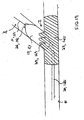
- a first guidewire 21 is advanced through a main vessel M in direction D such that distal end 22 of guidewire 21 extends past the intersection of a main vessel M and a branch vessel Br.
- main catheter 12 is then advanced in direction D over guidewire 21 such that a main stent 25, (which is supported at a distal end of catheter 12, as shown), is oriented such that side hole 27 of stent 25 is positioned generally adjacent the ostium of branch vessel Br. (Guidewire 21 is received within a lumen in catheter 12.)
- stent 25 may be crimped down onto the distal end of side sheath 14, as shown.
- distal end 16 of catheter 14 has tungsten, or other suitable radiopaque material, deposited thereon such that it can be viewed and positioned fluoroscopically.
- stent 25 is initially crimped onto balloon 11 with distal end 16 of side sheath 14 projecting outwardly through side opening 27 as shown.
- fluoroscopic positioning of distal end 16 aligns side opening 27 to branch vessel Br, as main catheter 12 supporting stent 25 and side sheath 14 initially move together when stent 25 is initially crimped onto balloon 11.
- a second guidewire 31 can then be advanced out of distal end 16 of side sheath 14, passing through side opening 27 in stent 25 and into branch vessel Br.
- balloon 11 may be partially or fully inflated, thereby expanding main stent 25 so as to provide an access space for a distal end 26 of second catheter 20 ( Fig. 9 ) to be advanced therethrough, (after side sheath 14 has been removed as shown in Fog. 8B).
- second catheter 20 (as shown in Fig. 9 ) can instead be used in place of side sheath 14 to deploy guidewire 31, (avoiding the step shown in Fig. 8A and 8B ).
- main stent 25 is at least partially deployed within main vessel M; and the distal end of second catheter 20 is then received within the at least partially deployed main stent 25.
- Figs. 9 and 10 additional sequential steps, as illustrated in Figs. 9 and 10 , are carried out after the steps illustrated in Figs. 6 to 8B to deploy a branch stent in a branch vessel with the branch stent extending through a side opening in the main stent.
- Fig. 9 is similar to Fig. 8B , but side sheath 14 has instead been replaced with second catheter 20 which has been advanced over guidewire 31.
- Branch stent 40 is disposed on the distal end 26 of catheter 20.
- distal end 26 of catheter 20 can be advanced over guidewire 31 such that stent 40 is advanced through side hole 27 in stent 25 and is positioned in branch vessel Br.
- side sheath 14 is used to position guidewire 31, and is then removed and replaced by second catheter 20.
- second catheter 20 is instead used to position guidewire 31 itself.
- stent 40 can then be fully deployed within branch vessel Br by inflating second balloon 13 disposed at distal end 26 of catheter 20, Main stent 25 can be fully deployed by inflation of balloon 11 either before, after or concurrently with, branch stent 40 being deployed by inflation of balloon 13.
- stent 40 may further comprise a contact portion 42 which remains disposed within side opening 27 thereby securing the proximal end of stent 40 to side opening 27 of stent 25, thereby providing a bifurcated stent arrangement covering vessel intersection I.
- catheter system 10 (comprising catheter 12, side sheath 14 or catheter 20, and guidewires 21 and 31) can be removed after deployment of stents 25 and 40, leaving a bifurcated support at the intersection of main vessel P and branch vessel Br as shown.
- balloon 13 on catheter 14 can then be inflated to deploy radially expandable portions 29 extending laterally outward from the edges of side opening 27, such that portions 29 are pushed against the walls of branch vessel Br, such that side opening 27 is positioned in registry with the ostium of branch vessel Br. Further description of such radially expandable portions 29 which extend laterally outward from the edges of side opening 27 is set forth in Published PCT Patent Application WO 99/00835, filed 01/14/98 .
- the delivery system of the present invention may be employed in a method of aligning a side opening 27 in a main stent 25 in registry with the ostium of a branch vessel Br, comprising: advancing a first guidewire 21 through a main vessel M such that a distal end of guidewire 21 extends past intersection I of main vessel M and the branch vessel Br; advancing main stent 25 over first guidewire 21 with a dual lumen catheter system 10, wherein first guidewire 21 is received within a first lumen of main catheter 12; positioning a side sheath 14 received through the second lumen of dual lumen catheter system 10 such that a distal end 16 of side sheath 14 is positioned at intersection I of main vessel M and branch vessel Br; and advancing second guidewire 31 through side sheath 14 and out through the side opening 27 in main stent 25 and into branch vessel Br, thereby aligning side opening 27 in main stent 25 with the ostium of branch vessel Br.
- a branch stent 40 is advanced over second guidewire 31 and out through the side
- side sheath 14 is positioned through the second lumen of dual lumen catheter 20 such that distal end 16 of side sheath 14 is positioned at intersection I of main vessel M and branch vessel Br by viewing the position of the distal end of the second catheter 20 under fluoroscopy.
- second guidewire 31 is advanced through side sheath 14 and into branch vessel Br by viewing the position of the distal end of second guidewire 31 under fluoroscopy.
- a first balloon 11 is disposed at a distal end of the dual lumen catheter 10 over first guidewire 31; and a second balloon 13 is disposed at a distal end of second catheter 20 over second guidewire 31.
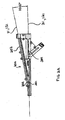
- the present stent delivery system 110 comprises a first catheter 112 having an attached flexible side sheath 114.
- An inflatable balloon 111 may optionally be positioned at the distal end of first catheter 112.
- first catheter 112 is receivable over a first guidewire 121 and flexible side sheath 114 is receivable over a second guidewire 131.
- the present stent delivery system 110 can be used to advantageously position first and second guidewires in respective main and branch vessels.
- the present stent delivery system 110 can be used to position main and branch stents in the main and branch vessels (over the respective main and branch guidewires).
- guidewires 121 and 131 are pre-positioned in respective main and branch vessels and stent delivery system 110 is advanced simultaneously thereover into vessel intersection I.
- the location of the vessel intersection and the moment in time at which side sheath 114 enters branch vessel Br can be determined by fluoroscopically viewing relative marker band rotation or separation as will be explained.
- stent 125 can be crimped down onto flexible side sheath 114, as shown.
- stent 125 is initially crimped onto balloon 111 with distal end 116 of side sheath 114 projecting outwardly through side opening 127 as shown.
- Fig. 21 is another illustration of the distal end of the system shown in Figs. 4 and 5 .
- a main guidewire 121 is first positioned in the main vessel M such that a distal end 122 of main guidewire 121 extends past vessel intersection I.
- stent delivery system 110 is then advanced to a position proximate vessel intersection I, wherein catheter 112 is received over first guidewire 121, and wherein main stent 125 is positioned over catheter 112 with flexible side sheath 114 positioned to pass through the interior of main stent 125 and out of side opening 127 in main stent 125, as shown.
- second guidewire 131 is then advanced through flexible side sheath 114 attached to catheter 112 and into branch vessel Br.
- guidewires 121 and 131 are pre-positioned in respective main and branch vessels M and Br, and system 110 is advanced thereover, with main catheter 112 passing over guidewire 121 and flexible side sheath 114 passing over guidewire 131.
- side opening 127 in main stent 125 is positioned in alignment with the ostium of branch vessel Br simply by the presence of second guidewire 131 (and flexible side sheath 114) extending from an interior of main stent 125 out through side opening 127 in main stent 125 and into branch vessel Br.
- the insertion of a branch stent over guidewire 131 through side opening 127 in main stent 125 and into branch vessel Br serves to align the side opening 127 with the ostium of branch vessel Br.
- stent delivery system 110 (comprising catheter 112 and attached flexible side sheath 114), are subsequently advanced distally in direction D to the position as shown in Fig. 13 and 14 , with catheter 112 being advanced over first guidewire 121 while flexible side sheath 114 is advanced over second guidewire 131.
- an operator views relative movement between a radiopaque marker positioned on the flexible side sheath with respect to at least one radiopaque marker positioned on the catheter, wherein the relative marker movement indicates that a portion of the flexible side sheath adjacent the side opening in the main stent is advancing into the ostium of the branch vessel, thereby indicating the position of side opening 127 of main stent 125 with respect to the ostium of branch vessel Br.
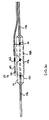
- a distal marker 150, a proximal marker 151 and a medial marker 152 may be disposed on catheter 112.
- the location of proximal marker 151 corresponds to the location of the proximal end of stent 125
- the location of distal marker 150 corresponds to the location of the distal end of stent 125
- the location of medial marker 152 corresponds to the location of side opening 127 of stent 125.
- At least one marker 155 is positioned on flexible side sheath 114 as shown. Marker 155 is positioned adjacent to medial marker 152.
- a marker 159 may be positioned at the distal end of side sheath 114. As such, the separation between markers 159 and 150 can be observed from the point in time when the distal end of side sheath 114 initially starts to advance into branch vessel Br over second guidewire 131.
- marker 155 will move in direction R relative to markers 150, 151 and 152.
- an increasing separation distance will occur between marker 155 positioned on flexible side sheath 114 and marker 152 positioned on catheter 112 as catheter 112 is advanced distally over first guidewire 121 while flexible side sheath 114 is simultaneously advanced distally over second guidewire 131.
- each of markers 152 and 155 are slightly elongated and rectangle shaped, (as shown), such that relative rotational movement therebetween can also be observed.
- Markers 150,151,152, 155 and 159 may be made of tungsten or gold.
- markers 152 and 155 When the operator views the relative motion (rotation or increasing separation) between markers 152 and 155, this indicates that a portion of flexible side sheath 114 has entered the ostium of branch vessel Br.
- the operator can also determine the position of the distal and proximal ends of stent 25 and the position of side opening 127 with respect to the ostium of branch vessel Br.
- branch stent 140 is advanced through the interior of main stent 125, passing through side opening 127 and into branch vessel Br.
- Fig. 15 is an illustration of branch stent 140, (disposed on the distal end of a deployment catheter 126), being advanced over second guidewire 131, passing through side opening 127 in main stent 125 into branch vessel Br.
- main catheter 112 of stent delivery system 110 may be used to deploy main stent 125 and then system 110 may be removed. Thereafter, a second (deployment) catheter 126 can be advanced over second guidewire 131 to position stent 140 for deployment in the branch vessel.
- stent 125 may be partially deployed in main vessel M by balloon 111 and branch stent 140 may be partially deployed in branch vessel Br by an optional balloon 115 on the distal end of side sheath 114 which is advanced through the partially expanded interior of main stent 125, passing out through side opening 127 in main stent 125 while stent delivery system 110 remains adjacent vessel intersection I.
- Fig. 17 is an illustration of the deployment of branch stent 140 by a balloon 113 disposed on the distal end of second catheter 126, which is itself received over second guidewire 131.
- an inflatable balloon 113 disposed at the distal end of second catheter 126 is used to deploy branch stent 140.
- Fig. 18 is an illustration of the fully deployed main and branch stents 125 and 140 with guidewires 121 and 131 and stent delivery system 110 removed.
- stent 140 may further comprise a contact portion 142 which remains disposed within side opening 127 thereby securing the proximal end of stent 140 to side opening 127 of stent 125, thereby providing a bifurcated stent arrangement covering vessel intersection I.
- a contacting portion 142 is further described in co-pending PCT Patent Application WO 99/00835, filed 01/14/98 .
- Fig. 19 shows an example with outwardly expandable portions disposed around the side opening on the main stent.
- balloon 113 on catheter 126 can also be inflated to deploy radially expandable portions 129 which extend laterally outward from an initial position flush with the cylindrical body of stent 125 to a position where portions 129, (disposed around the edges of side opening 127), are anchored against the walls of branch vessel Br, such that side opening 127 is positioned in registry with the ostium of branch vessel Br.
- radially expandable portions 129 which extend laterally outward from the edges of side opening 127 is set forth in Published PCT Patent Application No. WO 99/00835 filed 01/14/98 .
- the delivery system of the present invention may be used in kits comprising the delivery system of the present invention and instructions for use setting forth any of the methods for use described herein.
- the delivery system of the present invention may also be employed in a method of positioning a main stent 125 at a vessel bifurcation (intersection I) such that a side opening 127 in main stent 125 is positioned at the ostium of branch vessel Br, comprising: positioning a main guidewire 121 in the main vessel M such that a distal end of the main guidewire 121 extends past the bifurcation; advancing a stent delivery system 110 to a position proximate the bifurcation I, the stent delivery system 110 comprising a catheter 112 with a flexible side sheath 114 attached thereto, wherein catheter 112 is received over main guidewire 121, and wherein the main stent 125 is positioned over catheter 112 with the flexible side sheath 114 positioned to pass through the interior of main stent 125 and out of side opening 127 in main stent 125; advancing a branch guidewire 131 through flexible side sheath 114 attached to catheter 112 and into branch vessel Br
- viewing relative movement of a marker 155 or 159 positioned on flexible side sheath 114 with respect to at least one marker 151, 152, 150 positioned on catheter 112 comprises: viewing an increasing separation distance between marker(s) 155, 159 positioned on flexible side sheath 114 with respect to at least one marker 150, 151, 152 positioned on catheter 112 as catheter 112 is advanced over first guidewire 121 while flexible side sheath 114 is simultaneously advanced over second guidewire 131.
- the at least one marker positioned on the catheter may comprise viewing markers positioned adjacent the distal and proximal ends of the main stent.
- the distal end of a second catheter 126 may be advanced over branch guidewire 131 and into branch vessel Br.
- a branch stent 140 may then be deployed within branch vessel Br, wherein branch stent 140 is positioned on the distal end of second catheter 126.
- the delivery system of the present invention may be employed in a method of positioning a main stent 125 at a vessel bifurcation (intersection I) such that a side opening 127 in main stent 125 is positioned at the ostium of branch vessel Br, comprising: positioning a main guidewire 121 in the main vessel M such that a distal end of main guidewire 121 extends past the bifurcation; advancing a stent delivery system 110 to a position proximate the bifurcation, the stent delivery system comprising a catheter 112 with a flexible side sheath 114 attached thereto, wherein catheter 112 is received over main guidewire 121, and wherein main stent 125 is positioned over catheter 112 with flexible side sheath 114 positioned to pass through the interior of main stent 125 and out of side opening 127 in main stent 125; advancing branch guidewire 131 through flexible side sheath 114 and into branch vessel Br; and subsequently, advancing catheter 112 over main guide
- a stent delivery system 110 for positioning a main stent 125 at a vessel bifurcation I such that side opening 127 in main stent 125 is positioned at the ostium of branch vessel Br, comprising: first guidewire 121; catheter 112 receivable over first guidewire 121, catheter 112 having at least one marker 150, 151, 152 positioned thereon; a flexible side sheath 114 attached to catheter 112, flexible side sheath 114 having at least one marker 155, 159 positioned thereon; and a second guidewire 131 receivable through the flexible side sheath.
- a stent delivery system 110 is described for positioning a main stent 125 at a vessel bifurcation I such that a side opening 127 in main stent 125 is positioned at the ostium of branch vessel Br, comprising: a catheter 112 having at least one marker 150, 151, 152 positioned thereon; and a flexible side sheath 114 attached to catheter 112, flexible side sheath 114 having at least one marker 155, 159 positioned thereon.
- a mechanism may be disposed at the proximal end of present invention, for simultaneously handling respective main and branch guidewires.
- a guidewire hub 200 is adapted with channels 201 and 202 passing therethrough in which guidewires 121 and 131 are passed, as shown.
- guidewire hub 200 can instead be used to receive guidewires 21 and 31 therethrough.
- the dimensions shown in Fig. 20 are understood to be exemplary, not limiting.
- side sheath 114 and main catheter 112 separate from one another at point 117, which may be approximately 10 cm from their respective distal ends. Such a length of separation has been founded to be advantageous when rotating system 110 as it is being advanced distally in a patient.
- guidewires 21 and 31 are received through guidewire hub 200 such that the guidewires are positioned at an angle to one another.
- This angle ranges from 0° to 20°. In another aspect, this angle is less than or equal to 10°.
- An advantage of angling the guidewires with respect to one another in this fashion, at these preferred angles, is that excessive friction is avoided when positioning or moving the guidewires. As such, simultaneous handling of the wires is facilitated.
- the guidewires are held close enough together such that an operator is able to simultaneously grasp and hold onto both guidewires with one hand while withdrawing the system over the two wires with the other hand.
- the guidewires are held far enough apart such that separate syringes can access each of channels 201 and 202, or separate luer fittings can be positioned to cover each of the proximal ends of channels 201 and 202.
- kits comprising: any of the delivery systems set forth herein, in combination with instructions for use setting forth any of the methods described herein.
- a kit 200 comprising a catheter system 110 (or alternately 10) and instructions for use 202 is also provided.
- Instructions for use 202 may comprise instructions for use comprising any of the methods of use described herein, including methods for deploying a main stent such that a side hole in the main stent is positioned in registry with the ostium of a branch vessel.
- Instructions for use 202 may be in written or machine readable form, as desired.
Abstract
Description
- The present invention relates to catheter systems for delivering stents.
- A type of endoprosthesis device, commonly referred to as a stent, may be placed or implanted within a vein, artery or other tubular body organ for treating occlusions, stenoses, or aneurysms of a vessel by reinforcing the wall of the vessel or by expanding the vessel. Stents have been used to treat dissections in blood vessel walls caused by balloon angioplasty of the coronary arteries as well as peripheral arteries and to improve angioplasty results by preventing elastic recoil and remodeling of the vessel wall. Two randomized multicenter trials have recently shown a lower restenosis rate in stent treated coronary arteries compared with balloon angioplasty alone (Serruys, PW et al., New England Journal of Medicine 331: 489-495 (1994) and Fischman, DL et al. New England Journal of Medicine 331:496-501 (1994)). Stents have been successfully implanted in the urinary tract, the bile duct, the esophagus and the tracheo-bronchial tree to reinforce those body organs, as well as implanted into the neurovascular, peripheral vascular, coronary, cardiac, and renal systems, among others. The term "stent" as used in this Application is a device which is intraluminally implanted within bodily vessels to reinforce collapsing, dissected, partially occluded, weakened, diseased or abnormally dilated or small segments of a vessel wall.
- One of the drawbacks of conventional stents is that they are generally produced in a straight tubular configuration. The use of such stents to treat diseased vessels at or near a bifurcation (branch point) of a vessel may create a risk of compromising the degree of patency of the main vessel and/or its branches, or the bifurcation point and also limits the ability to insert a branch stent into the side branch if the result of treatment of the main, or main, vessel is suboptimal. Suboptimal results may occur as a result of several mechanisms, such as displacing diseased tissue, plaque shifting, vessel spasm, dissection with or without intimal flaps, thrombosis, and embolism.
-
WO 96/34580 - As described in
PCT Patent Application Publication No. WO 99/00835 filed 01/14/98 - For example, in various approaches, the insertion of separate guidewires into both the main and branch vessels is required before the positioning of a main stent in a main vessel with a branch stent projecting through a side opening in the main stent into a branch vessel. Specifically, main and branch stents are advanced over the separate guidewires which have been pre-guided one after another into the respective main and branch vessels, such that the main stent can be deployed within the main vessel and the branch stent can be deployed (passing through the side opening in the main stent into the branch vessel). Unfortunately, when attempting to guide two separate guidewires through the main vessel such that one enters the branch vessel, the two guidewires typically tend to wrap around one another and become entangled. Accordingly, time and effort is required to individually position each of the two guidewires one after another.
- An additional disadvantage of positioning conventional stents is the difficulty in visualizing the stents during and after deployment, and in general, the fact that they arc not readily imaged by low-cost and easy methods, such as x-ray or ultrasound imaging.
- As will be explained, an advantage of the present system is that it may be used for deploying a main stent in a main vessel with a side hole in the main stent positioned at a branch vessel. Optionally, the system may further position a branch stent in the branch vessel, wherein the branch stent is deployed through an opening in the side of the main stent with the side opening being in registry with the ostium of the branch vessel. In various aspects of the present invention, another advantage of the present system is that it avoids having to separately position first and second guidewires within the respective main and branch vessels prior to deployment of main and branch stents thereover. Rather, in various aspects of the present invention, only a single guidewire needs to initially be placed within the main vessel, with the present system subsequently deploying both the main and branch stents thereover.
- In addition, methods of positioning a main stent at a vessel bifurcation such that a side opening in the main stent is positioned in registry with the ostium of a branch vessel are described. A first guidewire can be positioned in the main vessel such that a distal end of the main guidewire extends past the bifurcation. Thereafter, the present system, (comprising either a main catheter with a slidably positionable side sheath or side catheter, or a main catheter with an attached, non-sliding, side sheath or side catheter), can be advanced to a position proximate the bifurcation, wherein the main catheter can be advanced over the main guidewire, and wherein the main stent can be positioned over the main catheter. The distal end of the flexible side sheath (or second catheter can be positioned to pass through the interior of the main stent, (which positioned over the distal end of the main catheter), and out of the side opening in the main stent.
- Thereafter, a branch guidewire can be advanced through the flexible side sheath (or second catheter) into the branch vessel. To assist in guiding the second guidewire into the branch vessel, the flexible side sheath (or second catheter) may taper to a narrow distal end, which may also be curved slightly outwardly.
- Subsequently, the system can be advanced with the main catheter advancing over the first guidewire as the flexible side sheath (or second catheter) concurrently advances over the second (ie: branch) guidewire. The side opening in the main stent can be positioned in alignment with the ostium of the branch vessel due solely to the presence of the second guidewire extending from an interior of the main stent out through the side opening in the main stent and into the branch vessel.
- In certain examples (in which the flexible side sheath or second catheter is slidably moveable with respect to a main catheter), the second lumen of the dual lumen catheter (through which the flexible side sheath or second catheter passes) is formed from pebax and graphite, thereby reducing sliding friction when the flexible side sheath (or second catheter) is passed therethrough. Accordingly, the distal end of the side sheath, (which is received through the second lumen of the dual lumen catheter), can easily be slidably positioned to a desired location at the intersection of the main and branch vessels such that the dual lumen catheter can be positioned at a desired location to deploy the main stent within the main vessel.
- In certain examples (in which the flexible side sheath or second catheter is not slidably moveable with respect to the main catheter, but is instead attached thereto), the distal end of the side sheath, (or second catheter), is positioned at a desired location at the intersection of the main and branch vessels by advancing the main catheter over the first guidewire in the main vessel such that the main catheter can be positioned at a desired location to deploy the main stent within the main vessel.
- In both examples, after the distal end of the side sheath (or second catheter) is positioned at the vessel intersection, a second guidewire can then be advanced through the side sheath (or second catheter) to pass out of the distal end of the side sheath (or second catheter), passing through the side opening in the main stent and into the branch vessel, thereby aligning the side opening of the main stent in registry with the ostium of the branch vessel. Thereafter, the main stent may be deployed within the main vessel, such as by inflating a first balloon disposed over the first guidewire at a distal end of the main catheter. The delivery system of the present invention may be employed in a method of delivering main and branch stents into the intersection of a main vessel and a branch vessel such that a side opening in the main stent is positioned in registry with the ostium of the branch vessel, and such that the branch stent extends through the side opening in the main stent and into the branch vessel. This can be accomplished by deploying a main stent within the main vessel such that a side opening in the main stent is in registry with the ostium of the branch vessel with a second guidewire passing out through the side opening in the main stent and into the branch vessel, as described above. A branch stent is then subsequently advanced over the second guidewire and into the branch vessel such that the branch stent passes out through the side opening in the main stent and into the branch vessel. (A separate deployment catheter, or alternatively, the second catheter itself may be used for positioning and deploying the branch stent in the branch vessel). The main stent may optionally include radially expandable portions which protrude outwardly from the side opening in the main stent and into the walls of the branch vessel, holding the side opening in registry with the ostium of the branch vessel.
- The side opening in the main stent can be positioned in alignment with the ostium of the branch vessel by viewing relative movement of radiopaque markers positioned on each of the main catheter and the flexible side sheath (or second catheter). The relative marker movement indicates that the distal portion of the flexible side sheath (or second catheter) which is positioned adjacent the side opening in the main stent is advancing into the ostium of the branch vessel, thereby indicating the position of the side opening of the main stent with respect to the ostium of the branch vessel. The flexible side sheath (or second catheter) will deflect into the branch vessel as it is advanced over the second guidewire, (while the main catheter itself moves distally along through the main vessel over the first guidewire).
- Such relative movement of the radiopaque markers may be viewed as a rotation of a marker positioned on the flexible side sheath with respect to a marker(s) positioned on the main catheter, or as a separation between the marker on the flexible side sheath (or second catheter) with respect to a marker(s) on the main catheter. According to the invention the marker on the flexible side sheath (or second catheter) is positioned adjacent a marker on the main catheter, such that the relative marker motion will be viewable in an image as a separation occurring between the two markers. In addition, markers may be positioned at the distal ends of the flexible side sheath (or second catheter) and the main catheter, such that the separation between these markers will be relatively larger, and thus can be easily viewed. Moreover, when the markers are positioned at the distal ends of the main stent and side member, the surgeon will view the separation of these markers earlier than would be the case if these markers were disposed at a more proximal location.
- In addition, a plurality of markers may be positioned on the catheter with a marker positioned at locations corresponding to each of the proximal and distal ends of the main stent. A medial marker may also be included, positioned halfway between the distal and proximal markers, for indicating the position of the side hole in the main stent, (which is preferably positioned halfway between the distal and proximal ends of the stent).
- The relative movement of the markers positioned on the catheter and those positioned on the flexible side sheath (or second catheter) can be observed fluoroscopically as the markers are radiopaque and are preferably made of suitable materials including tungsten and gold.
- Using the delivery system of the present invention, the main stent is deployed in the main vessel, (such as by an inflatable balloon at the distal end of the main catheter). Thereafter, a branch stent may be advanced through the at least partially deployed main stent and positioned in the branch vessel. The branch stent is advanced through the at least partially deployed main stent by a catheter which then deploys the branch stent in the branch vessel, (such as by an inflatable balloon at the distal end of the deployment catheter).
- In an example (in which the flexible side sheath is slidably movable with respect to the main catheter) the branch stent can be deployed by first removing the side sheath from the second lumen of the dual lumen catheter, thereby leaving the second guidewire in position in the branch vessel. Thereafter, the deployment catheter can then be advanced over the second guide wire with its distal end extending into the branch vessel. A balloon disposed on the distal end of this deployment catheter can then be used to deploy the branch stent within the branch vessel. Alternately, the entire catheter system (comprising both the main catheter and the slidably attached side sheath) can be removed leaving the two guidewires in place such that the deployment catheter can be advanced over the second guidewire and into the branch vessel.
- In an example (in which the flexible side sheath is not slidably movable with respect to the main catheter) the branch stent may be deployed by removing the entire system, (comprising both the main catheter and attached flexible side sheath), leaving the two guidewires in place such that the deployment catheter can then be advanced over the second guidewire and into the branch vessel. As such, the second catheter can then be advanced over the second guide wire with its distal end extending into the branch vessel.
- Alternatively the first and second guidewires may first be positioned in the respective main and branch vessels. Thereafter, the main catheter can be advanced over the first guidewire and the flexible side sheath can simultaneously be advanced over the second guidewire. As such, a surgeon viewing movement between markers on the main catheter and the flexible side sheath can see exactly when and where the flexible side sheath enters the branch vessel.
- The branch stent may optionally comprise a contact portion at its proximal end to secure the proximal end of the branch stent to the interior of the main stent through the side opening in the main stent.
- In an example the distal end of the side sheath is positioned at the intersection of the main vessel and the branch vessel by viewing its position under fluoroscopy. Also, the second guidewire is inserted through the side sheath (or second catheter) and into the branch vessel under fluoroscopic viewing
- An apparatus for aligning a side opening in a main stent in registry with the ostium of the branch vessel is described. A dual lumen catheter system in which a first guidewire is slidably received within a first lumen of the main catheter and a side sheath (or alternatively, the second catheter) is slidably received within the second lumen of this dual lumen catheter is described. A second guidewire is slidably received within the lumen of the side sheath. A main catheter with an attached flexible side sheath (or second catheter) is described.
- To assist in guiding the second guidewire into the branch vessel, the side sheath (or second catheter) may taper to a narrow distal end, which may be curved slightly outwardly and which may comprise tungsten or other suitable radiopaque material such that it may be fluoroscopically viewed. A first balloon can be disposed over the first guidewire at a distal end of the dual lumen catheter and a second balloon is disposed over the second guidewire at a distal end of the second catheter (ie: the deployment catheter) which can be received within the second lumen of the dual lumen catheter.
- An advantage of the present stent delivery system is that it avoids having to separately position first and second guidewires within the respective main and branch vessels prior to deployment of the main and branch stents thereover. Rather, only a single guidewire needs to initially be placed within the main vessel, with the delivery system subsequently deploying both the main and branch stents thereover.
- The main stent may optionally include outwardly expandable portions which can be expanded from an initial position which is flush with the cylindrical body of the stent to protrude outwardly from the side opening in the main stent, thereby anchoring into the walls of the branch vessel, holding the side opening in registry with the ostium of the branch vessel. In an exemplary aspect, the cylindrical body of the main stent has an even surface, with an expandable portion positioned within the side opening of the cylindrical body, such that it is flush with the cylindrical body prior to expansion.
- In addition, the branch stent may optionally comprise a contacting portion at its proximal end to secure the proximal end of the branch stent to the side opening in the main stent. In an exemplary aspect, the contacting portion comprises a flared proximal end.
- Applications of the present system include the cardiac, coronary, renal, peripheral vascular, gastrointestinal, pulmonary, urinary and neurovascular systems and the brain. Further advantages of the present stent delivery system are that it provides an improved stent delivery apparatus, which may deliver main and branch stents to: 1) completely cover the bifurcation point of bifurcation vessels; 2) be used to treat lesions in one branch of a bifurcation while preserving access to the other branch for future treatment; 3) allow for differential sizing of the stents in a bifurcated stent apparatus even after a main stent is implanted; 4) treat bifurcation lesions in a bifurcated vessel where the branch vessel extends from the side of the main vessel; and 5) be marked with, or at least partly constructed of, material which is imageable by commonly used intraluminal catheterization visualization techniques including but not limited to ultrasound or x-ray.
- As described herein, a side hole in the main stent refers to a relatively large hole which is intended to be aligned with the ostium of the branch vessel, as opposed to being any of the multiple passageways through the side of the main stent between respective struts in the stent geometry. Accordingly, the side hole in the main stent is a hole which is understood to be larger than other passages through the stent. In certain aspects, this side hole is defined by a band of continuous material which defines the perimeter of the side hole. This continuous band of material comprises discontinuities over its length so that the area of the side hole expands together with the expansion of the stent. In various aspects, the continuous band comprises protrusions which project inwardly from a peripheral edge of the side opening. Possibly, these protrusions (or expandable portions) are initially aligned within a cylindrical envelope of the tubular body of the main stent. The invention is defined by appended claim 1 with preferred embodiments defined in the dependent claims.
-
-
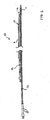
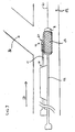
Fig 1 . is an illustration of a dual lumen catheter with a main catheter and an attached slidably movable side sheath, the side sheath being slidably received within a second lumen of the dual lumen catheter. -
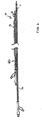
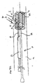
Fig 2 . is an illustration of a dual lumen catheter having similar toFig. 1 , but having a second catheter slidably received within a second lumen of the dual lumen catheter, with balloons positioned on the distal ends of both of the main catheter and the second catheter. -
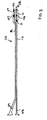
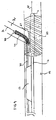
Fig 3 is an illustration of a second aspect of the present stent delivery system, showing a main catheter with a flexible side sheath attached thereto. -
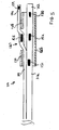
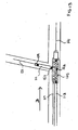
Fig 4 is a close up illustration of the distal end of the stent delivery system ofFig. 3 with a main stent positioned thereon. -
Fig. 5 is a sectional side elevation view correspondingFig. 4 , showing the markers in alignment, prior to entering the branch vessel. -
Fig. 6 is an illustration of a placement of first guidewire within a main vessel. -
Fig. 7 is an illustration of the main catheter and side sheath ofFig. 1 advanced over the first guidewire to a position where the side opening in the main stent is adjacent with the ostium of the branch vessel. -
Fig. 8A is an illustration corresponding toFig. 7 , but with the second guidewire advanced out of the distal end of the side sheath, through the side opening in the main stent and into the branch vessel. -
Fig. 8B corresponds toFig. 8A , but with the flexible side sheath removed. -
Fig. 9 is an illustration corresponding toFig. 8B , but with the branch stent advanced over the second guidewire and through the side opening in the main stent and into the branch vessel by a second catheter received within the second lumen of the dual lumen catheter. -
Fig. 10 is an illustration of the deployment of the branch stent ofFig. 9 by a second balloon disposed over the second guidewire. -
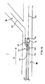
Fig. 11 is an illustration of the catheter and attached flexible side sheath ofFigs. 3 and4 advanced over the first guidewire to a position near the ostium of the branch vessel. -
Fig. 12 is an illustration corresponding toFig. 11 , but with the second guidewire advanced out of the distal end of the side sheath, through a side opening in a main stent and into the branch vessel. -
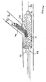
Fig. 13 is an illustration corresponding toFig. 12 , but with the catheter and attached flexible side sheath advanced over the first and second guidewire such that the distal end of the flexible side sheath is deflected into the branch vessel, showing the separation between radiopaque markers on the catheter and flexible side sheath. -
Fig. 14 is a sectional side elevation view correspondingFig. 13 . -
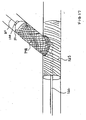
Fig. 15 is an illustration corresponding toFig. 14 , but showing the main catheter and flexible side sheath removed with a branch stent (positioned on a deployment catheter) advanced over the second guidewire and through the side opening in the main stent and into the branch vessel. -
Fig. 16 is an illustration corresponding toFig. 14 , but showing the branch stent (positioned on a deployment balloon attached to the flexible side sheath) advanced over the second guidewire and through the side opening in the main stent and into the branch vessel. -
Fig. 17 is an illustration of the further deployment of the branch stent ofFig. 15 by a balloon disposed on a deployment catheter received over the second guidewire. -
Fig. 18 is an illustration of the fully deployed main and branch stents with the guidewires and stent delivery system removed. -
Fig. 19 shows an example with outwardly expandable portions disposed around the side opening on the main stent fully deployed. -
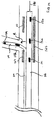
Fig. 20 is a side elevation view of the system ofFig. 4 , showing both proximal and distal ends of an example, showing exemplary dimensions.. -
Fig. 21 is another illustration of the distal end of the system shown inFigs. 4 and5 ., -
Fig. 22 is an illustration of an aspect of the proximal end of an example. -
Fig. 23 is an illustration of a kit comprising the present apparatus, and instructions for use. - The present invention provides systems for positioning first and second guidewires in respective main and branch vessels at a vessel bifurcation. In additional aspects, a system for aligning the side hole in a main stent in registry with the ostium of a branch vessel is provided. In further additional aspects, main and branch stents are deployed in the bifurcation over the first and second guidewires.
-
Figs. 1 ,2 and6 to 10 show a first aspect comprising a dual lumen catheter which comprises a main catheter and a flexible side sheath (or alternatively, a second catheter) which is slidably positionable with respect to the main catheter. -
Figs. 3 to 5 and11 to 17 and21 show a second aspect comprising a main catheter with a flexible side sheath (or alternatively, a second catheter) which is attached to the main catheter. -
Fig. 18 shows a fully deployed main and branch stent which may be deployed, andFig. 19 shows an example with outwardly expandable portions disposed around the side opening on the main stent fully deployed. - The present catheter system comprises a dual lumen catheter having a guidewire received through its first lumen. In one aspect, a side sheath is slidably received through the second lumen of the dual lumen catheter. A second guidewire is received through the side sheath and the side sheath is slidably positionable (with respect to a main catheter) so as to optionally align a side hole in a main stent disposed on a main catheter with the ostium of a branch vessel.
- In an alternative aspect, a second catheter is instead slidably received through the second lumen of the dual lumen catheter. The second catheter may optionally have a balloon disposed at its distal end such that first and second balloons are disposed over the first and second guidewires at the distal ends of the respective main and second catheters, for deploying main and branch stents respectively.
- Referring to
Fig. 1 , a duallumen catheter system 10 is provided comprising amain catheter 12 and aside sheath 14, whereinside sheath 14 is slidably received withinlumen 15 which may be formed as an extending side portion 9 ofcatheter 12 such thatside sheath 14 can be axially displaced with respect tocatheter 12. Theinterior lumen 15 of extending side portion 9 is preferably formed to reduce sliding friction withside sheath 14. In an example, extending side portion 9 ofcatheter 12 forminglumen 15 is fabricated of pebax with graphite. Alternatively, the inner surface oflumen 15 may have metal powders, glass beads, Teflon powder or other inorganic fillers imbedded therein. -
Side sheath 14 is flexible, (which aids in positioning its distal end to pass though a side hole in a main stent, as will be explained). - As will be explained with reference to
Figs. 7 to 10 , an advantage of the presentdual lumen catheter 12 is thatcatheter 12 can be positioned at a desired location so as to alignside hole 27 ofmain stent 25 at the ostium of a branch vessel by positioning thedistal end 16 ofside sheath 14 at the ostium of the branch vessel. Specificallydual lumen catheter 12 can be positioned proximal the intersection of the main and branch vessels to deploy amain stent 25 in the main vessel M withside sheath 14 positioned at the vessel intersection I to deploy asecond guidewire 31 passing out throughside hole 27 inmain stent 25 and into branch vessel Br such that only oneguidewire 21 needs to initially be positioned within main vessel M prior to subsequent deployment of main andbranch stents - As can be seen in
Fig. 2 , asecond catheter 20 can instead be slidably received in lumen 15 (in place of side sheath 14). Aballoon 11 disposed at the distal end ofdual lumen catheter 10 may be used to deploy a main stent in a main vessel. In this aspect,side sheath 14 may preferably be first removed (ie: withdrawn over guidewire 31) afterguide wire 31 has been positioned in the branch vessel. Alternatively, guidewire 31 may instead be positioned in branch vessel Br bysecond catheter 20, such thatside sheath 14 is not required. Thesecond catheter 20 having a balloon 13 disposed at its distal end is then advanced overguide wire 31 with balloon 13 deploying anoptional branch stent 40, as will be explained. - In a preferred aspect, the delivery system of the present invention is suitable for aligning a side hole in a main stent to a position in registry with the ostium of a branch vessel. This first aspect is illustrated in the sequential steps shown in
Figs. 6 to 8 . - In another preferred aspect, the delivery system of the present invention is suitable for deploying a branch stent in a branch vessel with the branch stent extending into the branch vessel through a side opening in the main stent. This second aspect is illustrated in the sequential steps shown in
Figs. 9 and10 . (The sequential steps shown inFigs. 9 and10 are accomplished after the sequential steps shown inFigs. 6 to 8 ). - Referring first to
Fig. 6 , afirst guidewire 21 is advanced through a main vessel M in direction D such that distal end 22 ofguidewire 21 extends past the intersection of a main vessel M and a branch vessel Br. - As shown in
Fig. 7 ,main catheter 12 is then advanced in direction D overguidewire 21 such that amain stent 25, (which is supported at a distal end ofcatheter 12, as shown), is oriented such thatside hole 27 ofstent 25 is positioned generally adjacent the ostium of branch vessel Br. (Guidewire 21 is received within a lumen incatheter 12.) As can be seen,stent 25 may be crimped down onto the distal end ofside sheath 14, as shown. Optionally,distal end 16 ofcatheter 14 has tungsten, or other suitable radiopaque material, deposited thereon such that it can be viewed and positioned fluoroscopically. Optionally,stent 25 is initially crimped ontoballoon 11 withdistal end 16 ofside sheath 14 projecting outwardly through side opening 27 as shown. As such, fluoroscopic positioning ofdistal end 16 alignsside opening 27 to branch vessel Br, asmain catheter 12 supportingstent 25 andside sheath 14 initially move together whenstent 25 is initially crimped ontoballoon 11. - As shown in
Fig. 8A , afterdistal end 16 ofcatheter 14 is positioned as shown, asecond guidewire 31 can then be advanced out ofdistal end 16 ofside sheath 14, passing through side opening 27 instent 25 and into branch vessel Br. As also shown,balloon 11 may be partially or fully inflated, thereby expandingmain stent 25 so as to provide an access space for adistal end 26 of second catheter 20 (Fig. 9 ) to be advanced therethrough, (afterside sheath 14 has been removed as shown in Fog. 8B). Alternatively, second catheter 20 (as shown inFig. 9 ) can instead be used in place ofside sheath 14 to deployguidewire 31, (avoiding the step shown inFig. 8A and8B ). In one aspect,main stent 25 is at least partially deployed within main vessel M; and the distal end ofsecond catheter 20 is then received within the at least partially deployedmain stent 25. - In further optional aspects, additional sequential steps, as illustrated in
Figs. 9 and10 , are carried out after the steps illustrated inFigs. 6 to 8B to deploy a branch stent in a branch vessel with the branch stent extending through a side opening in the main stent. Specifically,Fig. 9 is similar toFig. 8B , butside sheath 14 has instead been replaced withsecond catheter 20 which has been advanced overguidewire 31.Branch stent 40 is disposed on thedistal end 26 ofcatheter 20. As shown inFig. 9 ,distal end 26 ofcatheter 20 can be advanced overguidewire 31 such thatstent 40 is advanced throughside hole 27 instent 25 and is positioned in branch vessel Br. In various aspects,side sheath 14 is used to positionguidewire 31, and is then removed and replaced bysecond catheter 20. In alternate aspects,second catheter 20 is instead used to positionguidewire 31 itself. - As shown in
Fig. 10 ,stent 40 can then be fully deployed within branch vessel Br by inflating second balloon 13 disposed atdistal end 26 ofcatheter 20,Main stent 25 can be fully deployed by inflation ofballoon 11 either before, after or concurrently with,branch stent 40 being deployed by inflation of balloon 13. As can also be seen inFig. 18 ,stent 40 may further comprise a contact portion 42 which remains disposed within side opening 27 thereby securing the proximal end ofstent 40 to side opening 27 ofstent 25, thereby providing a bifurcated stent arrangement covering vessel intersection I. - Lastly, as can also be seen in
Fig. 18 ,catheter system 10, (comprisingcatheter 12,side sheath 14 orcatheter 20, andguidewires 21 and 31) can be removed after deployment ofstents - As shown in the optional step of
Fig. 19 , balloon 13 oncatheter 14 can then be inflated to deploy radially expandable portions 29 extending laterally outward from the edges ofside opening 27, such that portions 29 are pushed against the walls of branch vessel Br, such thatside opening 27 is positioned in registry with the ostium of branch vessel Br. Further description of such radially expandable portions 29 which extend laterally outward from the edges ofside opening 27 is set forth in PublishedPCT Patent Application WO 99/00835, filed 01/14/98 - The delivery system of the present invention may be employed in a method of aligning a
side opening 27 in amain stent 25 in registry with the ostium of a branch vessel Br, comprising: advancing afirst guidewire 21 through a main vessel M such that a distal end ofguidewire 21 extends past intersection I of main vessel M and the branch vessel Br; advancingmain stent 25 overfirst guidewire 21 with a duallumen catheter system 10, whereinfirst guidewire 21 is received within a first lumen ofmain catheter 12; positioning aside sheath 14 received through the second lumen of duallumen catheter system 10 such that adistal end 16 ofside sheath 14 is positioned at intersection I of main vessel M and branch vessel Br; and advancingsecond guidewire 31 throughside sheath 14 and out through theside opening 27 inmain stent 25 and into branch vessel Br, thereby aligningside opening 27 inmain stent 25 with the ostium of branch vessel Br. In additional aspects, abranch stent 40 is advanced oversecond guidewire 31 and out through theside opening 27 inmain stent 25 and into the branch vessel Br bysecond catheter 20. - In additional aspects,
side sheath 14 is positioned through the second lumen ofdual lumen catheter 20 such thatdistal end 16 ofside sheath 14 is positioned at intersection I of main vessel M and branch vessel Br by viewing the position of the distal end of thesecond catheter 20 under fluoroscopy. In additional aspects,second guidewire 31 is advanced throughside sheath 14 and into branch vessel Br by viewing the position of the distal end ofsecond guidewire 31 under fluoroscopy. - In preferred aspects, a
first balloon 11 is disposed at a distal end of thedual lumen catheter 10 overfirst guidewire 31; and a second balloon 13 is disposed at a distal end ofsecond catheter 20 oversecond guidewire 31. - Referring to
Figs. 3 to 5 , the presentstent delivery system 110 comprises afirst catheter 112 having an attachedflexible side sheath 114. An inflatable balloon 111 may optionally be positioned at the distal end offirst catheter 112. As is shown inFigs. 12 to 14 ,first catheter 112 is receivable over afirst guidewire 121 andflexible side sheath 114 is receivable over asecond guidewire 131. The presentstent delivery system 110 can be used to advantageously position first and second guidewires in respective main and branch vessels. In further aspects, the presentstent delivery system 110 can be used to position main and branch stents in the main and branch vessels (over the respective main and branch guidewires). - In another aspect, guidewires 121 and 131 are pre-positioned in respective main and branch vessels and
stent delivery system 110 is advanced simultaneously thereover into vessel intersection I. In this aspect, the location of the vessel intersection and the moment in time at whichside sheath 114 enters branch vessel Br can be determined by fluoroscopically viewing relative marker band rotation or separation as will be explained. - Referring to
Fig. 4 ,stent 125 can be crimped down ontoflexible side sheath 114, as shown. Preferably,stent 125 is initially crimped onto balloon 111 withdistal end 116 ofside sheath 114 projecting outwardly throughside opening 127 as shown.Fig. 21 is another illustration of the distal end of the system shown inFigs. 4 and5 . - In the following, a method of positioning
main stent 125 at a vessel bifurcation (intersection I) such that aside opening 127 inmain stent 125 is positioned at the ostium of a branch vessel Br is described. - Referring to
Fig. 6 , amain guidewire 121 is first positioned in the main vessel M such that a distal end 122 ofmain guidewire 121 extends past vessel intersection I. Referring next toFig. 11 ,stent delivery system 110 is then advanced to a position proximate vessel intersection I, whereincatheter 112 is received overfirst guidewire 121, and whereinmain stent 125 is positioned overcatheter 112 withflexible side sheath 114 positioned to pass through the interior ofmain stent 125 and out ofside opening 127 inmain stent 125, as shown. In one aspect, as shown inFig. 12 ,second guidewire 131 is then advanced throughflexible side sheath 114 attached tocatheter 112 and into branch vessel Br. In an alternate aspect, guidewires 121 and 131 are pre-positioned in respective main and branch vessels M and Br, andsystem 110 is advanced thereover, withmain catheter 112 passing overguidewire 121 andflexible side sheath 114 passing overguidewire 131. - In one aspect, side opening 127 in
main stent 125 is positioned in alignment with the ostium of branch vessel Br simply by the presence of second guidewire 131 (and flexible side sheath 114) extending from an interior ofmain stent 125 out through side opening 127 inmain stent 125 and into branch vessel Br. In this aspect, the insertion of a branch stent overguidewire 131 through side opening 127 inmain stent 125 and into branch vessel Br serves to align theside opening 127 with the ostium of branch vessel Br. - In another aspect, however,
stent delivery system 110, (comprisingcatheter 112 and attached flexible side sheath 114), are subsequently advanced distally in direction D to the position as shown inFig. 13 and14 , withcatheter 112 being advanced overfirst guidewire 121 whileflexible side sheath 114 is advanced oversecond guidewire 131. In this aspect, an operator views relative movement between a radiopaque marker positioned on the flexible side sheath with respect to at least one radiopaque marker positioned on the catheter, wherein the relative marker movement indicates that a portion of the flexible side sheath adjacent the side opening in the main stent is advancing into the ostium of the branch vessel, thereby indicating the position of side opening 127 ofmain stent 125 with respect to the ostium of branch vessel Br. - Specifically, referring to
Figs. 5 and14 , adistal marker 150, aproximal marker 151 and amedial marker 152 may be disposed oncatheter 112. The location ofproximal marker 151 corresponds to the location of the proximal end ofstent 125, the location ofdistal marker 150 corresponds to the location of the distal end ofstent 125, and the location ofmedial marker 152 corresponds to the location of side opening 127 ofstent 125. At least onemarker 155 is positioned onflexible side sheath 114 as shown.Marker 155 is positioned adjacent tomedial marker 152. In addition, amarker 159 may be positioned at the distal end ofside sheath 114. As such, the separation betweenmarkers side sheath 114 initially starts to advance into branch vessel Br oversecond guidewire 131. - As can be seen by comparing
Figs. 5 and14 , asstent delivery system 110 is advanced distally such that the distal end offlexible side sheath 114 is received in branch vessel Br, (Fig. 14 ),marker 155 will move in direction R relative tomarkers marker 155 positioned onflexible side sheath 114 andmarker 152 positioned oncatheter 112 ascatheter 112 is advanced distally overfirst guidewire 121 whileflexible side sheath 114 is simultaneously advanced distally oversecond guidewire 131. - In an additional aspect, each of
markers - When the operator views the relative motion (rotation or increasing separation) between
markers flexible side sheath 114 has entered the ostium of branch vessel Br. By viewing the position of markers 150,151 and 152, the operator can also determine the position of the distal and proximal ends ofstent 25 and the position ofside opening 127 with respect to the ostium of branch vessel Br. - Systems for deploying a branch stent into branch vessel Br with
main stent 125 positioned such thatside opening 127 is in registry with the ostium of branch vessel Br are described. In these aspects, as illustrated inFigs. 15 through 19 ,branch stent 140 is advanced through the interior ofmain stent 125, passing throughside opening 127 and into branch vessel Br. -
Fig. 15 is an illustration ofbranch stent 140, (disposed on the distal end of a deployment catheter 126), being advanced oversecond guidewire 131, passing through side opening 127 inmain stent 125 into branch vessel Br. As can be seen, in one aspect,main catheter 112 ofstent delivery system 110 may be used to deploymain stent 125 and thensystem 110 may be removed. Thereafter, a second (deployment)catheter 126 can be advanced oversecond guidewire 131 to positionstent 140 for deployment in the branch vessel. - In an alternative aspect, as shown in
Fig. 16 ,stent 125 may be partially deployed in main vessel M by balloon 111 andbranch stent 140 may be partially deployed in branch vessel Br by an optional balloon 115 on the distal end ofside sheath 114 which is advanced through the partially expanded interior ofmain stent 125, passing out through side opening 127 inmain stent 125 whilestent delivery system 110 remains adjacent vessel intersection I. -
Fig. 17 is an illustration of the deployment ofbranch stent 140 by aballoon 113 disposed on the distal end ofsecond catheter 126, which is itself received oversecond guidewire 131. In this aspect aninflatable balloon 113 disposed at the distal end ofsecond catheter 126 is used to deploybranch stent 140. -
Fig. 18 is an illustration of the fully deployed main andbranch stents guidewires stent delivery system 110 removed. As can also be seen,stent 140 may further comprise a contact portion 142 which remains disposed withinside opening 127 thereby securing the proximal end ofstent 140 to side opening 127 ofstent 125, thereby providing a bifurcated stent arrangement covering vessel intersection I. Such a contacting portion 142 is further described in co-pendingPCT Patent Application WO 99/00835, filed 01/14/98 - Lastly,
Fig. 19 shows an example with outwardly expandable portions disposed around the side opening on the main stent. Specifically,balloon 113 oncatheter 126 can also be inflated to deploy radially expandable portions 129 which extend laterally outward from an initial position flush with the cylindrical body ofstent 125 to a position where portions 129, (disposed around the edges of side opening 127), are anchored against the walls of branch vessel Br, such thatside opening 127 is positioned in registry with the ostium of branch vessel Br. Further description of such radially expandable portions 129 which extend laterally outward from the edges ofside opening 127 is set forth in PublishedPCT Patent Application No. WO 99/00835 filed 01/14/98 - The delivery system of the present invention may be used in kits comprising the delivery system of the present invention and instructions for use setting forth any of the methods for use described herein.
- The delivery system of the present invention may also be employed in a method of positioning a main stent 125 at a vessel bifurcation (intersection I) such that a side opening 127 in main stent 125 is positioned at the ostium of branch vessel Br, comprising: positioning a main guidewire 121 in the main vessel M such that a distal end of the main guidewire 121 extends past the bifurcation; advancing a stent delivery system 110 to a position proximate the bifurcation I, the stent delivery system 110 comprising a catheter 112 with a flexible side sheath 114 attached thereto, wherein catheter 112 is received over main guidewire 121, and wherein the main stent 125 is positioned over catheter 112 with the flexible side sheath 114 positioned to pass through the interior of main stent 125 and out of side opening 127 in main stent 125; advancing a branch guidewire 131 through flexible side sheath 114 attached to catheter 112 and into branch vessel Br; and subsequently, advancing catheter 112 over the main guidewire 121 while advancing flexible side sheath 114 over branch guidewire 131 while viewing relative movement of a marker 155 or 159 positioned on the flexible side sheath with respect to at least one marker 151, 152, 150 positioned on catheter 112, wherein the relative movement indicates that a portion of flexible side sheath 114 adjacent side opening 127 in main stent 125 is advancing into the ostium of branch vessel Br, thereby indicating the position of side opening 127 of main stent 125 with respect to the ostium of branch vessel Br.
- In various aspects, viewing relative movement of a
marker flexible side sheath 114 with respect to at least onemarker catheter 112, comprises: viewing an increasing separation distance between marker(s) 155, 159 positioned onflexible side sheath 114 with respect to at least onemarker catheter 112 ascatheter 112 is advanced overfirst guidewire 121 whileflexible side sheath 114 is simultaneously advanced oversecond guidewire 131. - \/iewing the at least one marker positioned on the catheter may comprise viewing markers positioned adjacent the distal and proximal ends of the main stent.
- The distal end of a
second catheter 126 may be advanced overbranch guidewire 131 and into branch vessel Br. Abranch stent 140 may then be deployed within branch vessel Br, whereinbranch stent 140 is positioned on the distal end ofsecond catheter 126. - The delivery system of the present invention may be employed in a method of positioning a
main stent 125 at a vessel bifurcation (intersection I) such that aside opening 127 inmain stent 125 is positioned at the ostium of branch vessel Br, comprising: positioning amain guidewire 121 in the main vessel M such that a distal end ofmain guidewire 121 extends past the bifurcation; advancing astent delivery system 110 to a position proximate the bifurcation, the stent delivery system comprising acatheter 112 with aflexible side sheath 114 attached thereto, whereincatheter 112 is received overmain guidewire 121, and whereinmain stent 125 is positioned overcatheter 112 withflexible side sheath 114 positioned to pass through the interior ofmain stent 125 and out ofside opening 127 inmain stent 125; advancingbranch guidewire 131 throughflexible side sheath 114 and into branch vessel Br; and subsequently, advancingcatheter 112 overmain guidewire 121 while advancingflexible side sheath 114 over branch guidewire 131 such thatside opening 127 inmain stent 125 is positioned at the ostium of branch vessel Br. - A
stent delivery system 110 is described for positioning amain stent 125 at a vessel bifurcation I such thatside opening 127 inmain stent 125 is positioned at the ostium of branch vessel Br, comprising:first guidewire 121;catheter 112 receivable overfirst guidewire 121,catheter 112 having at least onemarker flexible side sheath 114 attached tocatheter 112,flexible side sheath 114 having at least onemarker second guidewire 131 receivable through the flexible side sheath. - It may further comprise a
main stent 125 positioned oncatheter 112, and at least onemarker delivery system 110, preferably comprising distal andproximal markers stent delivery system 110 is described for positioning amain stent 125 at a vessel bifurcation I such that aside opening 127 inmain stent 125 is positioned at the ostium of branch vessel Br, comprising: acatheter 112 having at least onemarker flexible side sheath 114 attached tocatheter 112,flexible side sheath 114 having at least onemarker - A mechanism may be disposed at the proximal end of present invention, for simultaneously handling respective main and branch guidewires. Referring to
Fig. 20 , aguidewire hub 200 is adapted withchannels guidewire hub 200 can instead be used to receiveguidewires Fig. 20 are understood to be exemplary, not limiting. As can be seen inFig. 20 ,side sheath 114 andmain catheter 112 separate from one another atpoint 117, which may be approximately 10 cm from their respective distal ends. Such a length of separation has been founded to be advantageous whenrotating system 110 as it is being advanced distally in a patient. - As can be seen in
Fig. 22 ,guidewires 21 and 31 (or 121 and 131) are received throughguidewire hub 200 such that the guidewires are positioned at an angle to one another. This angle ranges from 0° to 20°. In another aspect, this angle is less than or equal to 10°. An advantage of angling the guidewires with respect to one another in this fashion, at these preferred angles, is that excessive friction is avoided when positioning or moving the guidewires. As such, simultaneous handling of the wires is facilitated. In addition, the guidewires are held close enough together such that an operator is able to simultaneously grasp and hold onto both guidewires with one hand while withdrawing the system over the two wires with the other hand. In addition, the guidewires are held far enough apart such that separate syringes can access each ofchannels channels - The delivery system of the present invention further may be used in kits comprising: any of the delivery systems set forth herein, in combination with instructions for use setting forth any of the methods described herein. Referring to
Fig. 23 , akit 200, comprising a catheter system 110 (or alternately 10) and instructions foruse 202 is also provided. Instructions foruse 202 may comprise instructions for use comprising any of the methods of use described herein, including methods for deploying a main stent such that a side hole in the main stent is positioned in registry with the ostium of a branch vessel. Instructions foruse 202 may be in written or machine readable form, as desired.
Claims (12)
- A delivery system (110) for positioning at a vessel bifurcation, the system comprising:a catheter (112) having a distal marker (150) and a proximal marker (151) positioned thereon; anda flexible side sheath (114) positioned alongside said catheter (112), the flexible side sheath (114) having a side sheath marker (155,159) positioned thereon,wherein said distal and proximal markers (150,151) are positioned relative to said side sheath marker (155,159) such that upon positioning of the flexible side sheath (114) at the vessel bifurcation, said flexible side sheath (114) is positioned and configured to enter a branch vessel, thereby separating said distal and proximal catheter markers (150,151) and said side sheath marker (155,159).
- The delivery system (110) of claim 1, further comprising a stent (125), wherein the catheter (112) is positioned through the stent (125).
- The delivery system (110) of claim 1, wherein said catheter further comprises a middle marker (152) positioned between said distal marker (150) and proximal marker (151).
- The delivery system (110) according to any one of the preceding claims, further comprising a balloon positioned at a distal end of the catheter.
- The delivery system (110) according to claim 1, wherein at least one of said catheter marker and said side sheath marker is radiopaque.
- The delivery system (110) of claim 5, wherein at least one radiopaque marker comprises at least one of gold and tungsten.
- The delivery system (110) of claim 3, wherein said side sheath marker (155) is substantially adjacent to said middle marker (152) before separating the markers on entry to the branch vessel.
- The delivery system (110) of claim 2, wherein said side sheath (114) is attached to said catheter (112) at a first end of said side sheath and is positioned through a side opening (127) of the stent (125) at a second end of said side sheath.
- The delivery system (110) of claim 1, wherein one of the distal marker (150) and the proximal marker (151) are positioned substantially adjacent the side sheath marker (155) before separating the markers on entry to the branch vessel.
- The delivery system (110) of claim 2, wherein said stent (125) has a side opening (127) configured to be positioned at an ostium of a branch vessel and the flexible side sheath (114) is positioned through the stent (125) such that a distal end of the flexible side sheath projects through said side opening.
- The delivery system (110) of claim 1, further comprising:a first guidewire receivable through said catheter (112); anda second guidewire receivable through said flexible side sheath (114).
- The delivery system (110) of claim 1, wherein the side sheath marker (155,159) includes a first side sheath marker (155) and a second side sheath marker (159).
Priority Applications (1)
| Application Number | Priority Date | Filing Date | Title |
|---|---|---|---|
| EP09176418A EP2165676B1 (en) | 1999-06-04 | 2000-06-02 | Catheter with side sheath |
Applications Claiming Priority (4)
| Application Number | Priority Date | Filing Date | Title |
|---|---|---|---|
| US32599699A | 1999-06-04 | 1999-06-04 | |
| US09/455,299 US6692483B2 (en) | 1996-11-04 | 1999-12-06 | Catheter with attached flexible side sheath |
| EP00938141A EP1182989B1 (en) | 1999-06-04 | 2000-06-02 | Catheter with side sheath |
| EP04078241A EP1512380B1 (en) | 1999-06-04 | 2000-06-02 | Stent delivery system for branched vessel |
Related Parent Applications (1)
| Application Number | Title | Priority Date | Filing Date |
|---|---|---|---|
| EP04078241A Division EP1512380B1 (en) | 1999-06-04 | 2000-06-02 | Stent delivery system for branched vessel |
Related Child Applications (1)
| Application Number | Title | Priority Date | Filing Date |
|---|---|---|---|
| EP09176418A Division EP2165676B1 (en) | 1999-06-04 | 2000-06-02 | Catheter with side sheath |
Publications (2)
| Publication Number | Publication Date |
|---|---|
| EP1857082A1 EP1857082A1 (en) | 2007-11-21 |
| EP1857082B1 true EP1857082B1 (en) | 2009-12-23 |
Family
ID=26985198
Family Applications (4)
| Application Number | Title | Priority Date | Filing Date |
|---|---|---|---|
| EP09176418A Expired - Lifetime EP2165676B1 (en) | 1999-06-04 | 2000-06-02 | Catheter with side sheath |
| EP00938141A Expired - Lifetime EP1182989B1 (en) | 1999-06-04 | 2000-06-02 | Catheter with side sheath |
| EP04078241A Expired - Lifetime EP1512380B1 (en) | 1999-06-04 | 2000-06-02 | Stent delivery system for branched vessel |
| EP07015811A Expired - Lifetime EP1857082B1 (en) | 1999-06-04 | 2000-06-02 | Stent delivery system for branched vessel |
Family Applications Before (3)
| Application Number | Title | Priority Date | Filing Date |
|---|---|---|---|
| EP09176418A Expired - Lifetime EP2165676B1 (en) | 1999-06-04 | 2000-06-02 | Catheter with side sheath |
| EP00938141A Expired - Lifetime EP1182989B1 (en) | 1999-06-04 | 2000-06-02 | Catheter with side sheath |
| EP04078241A Expired - Lifetime EP1512380B1 (en) | 1999-06-04 | 2000-06-02 | Stent delivery system for branched vessel |
Country Status (7)
| Country | Link |
|---|---|
| US (2) | US6692483B2 (en) |
| EP (4) | EP2165676B1 (en) |
| JP (1) | JP4416976B2 (en) |
| AT (3) | ATE452607T1 (en) |
| DE (3) | DE60016401T2 (en) |
| ES (2) | ES2293163T3 (en) |
| WO (1) | WO2000074595A1 (en) |
Cited By (1)
| Publication number | Priority date | Publication date | Assignee | Title |
|---|---|---|---|---|
| US8246670B2 (en) | 2006-08-23 | 2012-08-21 | Abbott Cardiovascular Systems Inc. | Catheter system and method for delivering medical devices |
Families Citing this family (228)
| Publication number | Priority date | Publication date | Assignee | Title |
|---|---|---|---|---|
| US7686846B2 (en) | 1996-06-06 | 2010-03-30 | Devax, Inc. | Bifurcation stent and method of positioning in a body lumen |
| US7238197B2 (en) * | 2000-05-30 | 2007-07-03 | Devax, Inc. | Endoprosthesis deployment system for treating vascular bifurcations |
| US8728143B2 (en) * | 1996-06-06 | 2014-05-20 | Biosensors International Group, Ltd. | Endoprosthesis deployment system for treating vascular bifurcations |
| US6325826B1 (en) * | 1998-01-14 | 2001-12-04 | Advanced Stent Technologies, Inc. | Extendible stent apparatus |
| US6599316B2 (en) * | 1996-11-04 | 2003-07-29 | Advanced Stent Technologies, Inc. | Extendible stent apparatus |
| AU4896797A (en) * | 1996-11-04 | 1998-05-29 | Davidson, Charles | Extendible stent apparatus and method for deploying the same |
| US7591846B2 (en) | 1996-11-04 | 2009-09-22 | Boston Scientific Scimed, Inc. | Methods for deploying stents in bifurcations |
| US7220275B2 (en) * | 1996-11-04 | 2007-05-22 | Advanced Stent Technologies, Inc. | Stent with protruding branch portion for bifurcated vessels |
| US8211167B2 (en) | 1999-12-06 | 2012-07-03 | Boston Scientific Scimed, Inc. | Method of using a catheter with attached flexible side sheath |
| US6692483B2 (en) * | 1996-11-04 | 2004-02-17 | Advanced Stent Technologies, Inc. | Catheter with attached flexible side sheath |
| US7341598B2 (en) | 1999-01-13 | 2008-03-11 | Boston Scientific Scimed, Inc. | Stent with protruding branch portion for bifurcated vessels |
| US6835203B1 (en) * | 1996-11-04 | 2004-12-28 | Advanced Stent Technologies, Inc. | Extendible stent apparatus |
| US7655030B2 (en) | 2003-07-18 | 2010-02-02 | Boston Scientific Scimed, Inc. | Catheter balloon systems and methods |
| US20050060027A1 (en) | 1999-01-13 | 2005-03-17 | Advanced Stent Technologies, Inc. | Catheter balloon systems and methods |
| US8257425B2 (en) * | 1999-01-13 | 2012-09-04 | Boston Scientific Scimed, Inc. | Stent with protruding branch portion for bifurcated vessels |
| EP1152711B1 (en) * | 1999-01-27 | 2005-07-06 | Boston Scientific Limited | Bifurcation stent delivery system |
| US6884258B2 (en) * | 1999-06-04 | 2005-04-26 | Advanced Stent Technologies, Inc. | Bifurcation lesion stent delivery using multiple guidewires |
| US7387639B2 (en) * | 1999-06-04 | 2008-06-17 | Advanced Stent Technologies, Inc. | Short sleeve stent delivery catheter and methods |
| US20060293695A1 (en) * | 1999-07-20 | 2006-12-28 | Ricci Donald R | Bifurcated stent delivery system and method of use |
| CN1409622A (en) * | 1999-09-23 | 2003-04-09 | 先进扩张技术公司 | Bifurcation stent system and method |
| EP1255506B1 (en) | 2000-02-18 | 2003-09-03 | E.V.R. Endovascular Researches S.A. | Endolumenal device for delivering and deploying an endolumenal expandable prosthesis |
| ITMI20020860A1 (en) * | 2002-04-22 | 2003-10-22 | E V R Endovascular Res Es S A | ENDOLUMINAL DEVICE TO TRANSPORT AND DISPLAY AN EXPANDABLE ENDOLUMINAL PROSTHESIS |
| US20030139803A1 (en) * | 2000-05-30 | 2003-07-24 | Jacques Sequin | Method of stenting a vessel with stent lumenal diameter increasing distally |
| US7208002B2 (en) | 2001-01-04 | 2007-04-24 | Boston Scientific Scimed, Inc. | Expansion-assisting delivery system for self-expanding stent |
| WO2002067653A2 (en) | 2001-02-26 | 2002-09-06 | Scimed Life Systems, Inc. | Bifurcated stent and delivery system |
| DE10118944B4 (en) * | 2001-04-18 | 2013-01-31 | Merit Medical Systems, Inc. | Removable, essentially cylindrical implants |
| US8617231B2 (en) * | 2001-05-18 | 2013-12-31 | Boston Scientific Scimed, Inc. | Dual guidewire exchange catheter system |
| US20030208142A1 (en) * | 2001-06-12 | 2003-11-06 | Boudewijn Alexander C | Vascular guidewire for magnetic resonance and /or fluoroscopy |
| US7547321B2 (en) * | 2001-07-26 | 2009-06-16 | Alveolus Inc. | Removable stent and method of using the same |
| US7147661B2 (en) | 2001-12-20 | 2006-12-12 | Boston Scientific Santa Rosa Corp. | Radially expandable stent |
| US20060253480A1 (en) * | 2002-04-06 | 2006-11-09 | Staples Peter E | Collaborative design process for a design team, outside suppliers, and outside manufacturers |
| US7993389B2 (en) | 2002-06-13 | 2011-08-09 | Existent Inc. | Guidewire system |
| US20050065596A1 (en) * | 2002-07-24 | 2005-03-24 | Xufan Tseng | Stents capable of controllably releasing histone deacetylase inhibitors |
| WO2004034767A2 (en) * | 2002-09-20 | 2004-04-29 | Flowmedica, Inc. | Catheter system for renal therapy |
| US20040093056A1 (en) * | 2002-10-26 | 2004-05-13 | Johnson Lianw M. | Medical appliance delivery apparatus and method of use |
| US7959671B2 (en) * | 2002-11-05 | 2011-06-14 | Merit Medical Systems, Inc. | Differential covering and coating methods |
| US7527644B2 (en) * | 2002-11-05 | 2009-05-05 | Alveolus Inc. | Stent with geometry determinated functionality and method of making the same |
| US7637942B2 (en) * | 2002-11-05 | 2009-12-29 | Merit Medical Systems, Inc. | Coated stent with geometry determinated functionality and method of making the same |
| US7875068B2 (en) | 2002-11-05 | 2011-01-25 | Merit Medical Systems, Inc. | Removable biliary stent |
| DE60231843D1 (en) * | 2002-11-08 | 2009-05-14 | Jacques Seguin | ENDOPROTHESIS FOR VESSEL FORKING |
| US7314480B2 (en) * | 2003-02-27 | 2008-01-01 | Boston Scientific Scimed, Inc. | Rotating balloon expandable sheath bifurcation delivery |
| US7367989B2 (en) * | 2003-02-27 | 2008-05-06 | Scimed Life Systems, Inc. | Rotating balloon expandable sheath bifurcation delivery |
| US7637934B2 (en) * | 2003-03-31 | 2009-12-29 | Merit Medical Systems, Inc. | Medical appliance optical delivery and deployment apparatus and method |
| US7604660B2 (en) * | 2003-05-01 | 2009-10-20 | Merit Medical Systems, Inc. | Bifurcated medical appliance delivery apparatus and method |
| US7604621B2 (en) | 2003-07-30 | 2009-10-20 | Boston Scientific Scimed, Inc. | Bifurcated stent delivery system |
| US8206320B2 (en) * | 2003-07-31 | 2012-06-26 | Cook Medical Technologies Llc | System and method for introducing multiple medical devices |
| US8298280B2 (en) * | 2003-08-21 | 2012-10-30 | Boston Scientific Scimed, Inc. | Stent with protruding branch portion for bifurcated vessels |
| US8500792B2 (en) | 2003-09-03 | 2013-08-06 | Bolton Medical, Inc. | Dual capture device for stent graft delivery system and method for capturing a stent graft |
| US20070198078A1 (en) * | 2003-09-03 | 2007-08-23 | Bolton Medical, Inc. | Delivery system and method for self-centering a Proximal end of a stent graft |
| US20080264102A1 (en) | 2004-02-23 | 2008-10-30 | Bolton Medical, Inc. | Sheath Capture Device for Stent Graft Delivery System and Method for Operating Same |
| US9198786B2 (en) | 2003-09-03 | 2015-12-01 | Bolton Medical, Inc. | Lumen repair device with capture structure |
| US8292943B2 (en) * | 2003-09-03 | 2012-10-23 | Bolton Medical, Inc. | Stent graft with longitudinal support member |
| US11259945B2 (en) | 2003-09-03 | 2022-03-01 | Bolton Medical, Inc. | Dual capture device for stent graft delivery system and method for capturing a stent graft |
| US7763063B2 (en) * | 2003-09-03 | 2010-07-27 | Bolton Medical, Inc. | Self-aligning stent graft delivery system, kit, and method |
| US11596537B2 (en) | 2003-09-03 | 2023-03-07 | Bolton Medical, Inc. | Delivery system and method for self-centering a proximal end of a stent graft |
| US7695508B2 (en) * | 2003-10-16 | 2010-04-13 | Minvasys Sa | Catheter system for stenting bifurcated vessels |
| US7641684B2 (en) * | 2003-10-16 | 2010-01-05 | Minvasys, Sa | Catheter system for stenting bifurcated vessels |
| US9278015B2 (en) * | 2003-10-16 | 2016-03-08 | Minvasys | Catheter system for stenting and drug treatment of bifurcated vessels |
| US9974674B2 (en) * | 2003-11-08 | 2018-05-22 | Cook Medical Technologies Llc | Branch vessel prothesis with positional indicator system and method |
| US7344557B2 (en) * | 2003-11-12 | 2008-03-18 | Advanced Stent Technologies, Inc. | Catheter balloon systems and methods |
| US7686841B2 (en) * | 2003-12-29 | 2010-03-30 | Boston Scientific Scimed, Inc. | Rotating balloon expandable sheath bifurcation delivery system |
| US7922753B2 (en) * | 2004-01-13 | 2011-04-12 | Boston Scientific Scimed, Inc. | Bifurcated stent delivery system |
| CA2555473A1 (en) * | 2004-02-17 | 2005-09-01 | Traxtal Technologies Inc. | Method and apparatus for registration, verification, and referencing of internal organs |
| US8012192B2 (en) * | 2004-02-18 | 2011-09-06 | Boston Scientific Scimed, Inc. | Multi-stent delivery system |
| US7225518B2 (en) * | 2004-02-23 | 2007-06-05 | Boston Scientific Scimed, Inc. | Apparatus for crimping a stent assembly |
| US8252014B2 (en) | 2004-03-03 | 2012-08-28 | Innovational Holdings Llc. | Rapid exchange balloon catheter with braided shaft |
| US20050209673A1 (en) | 2004-03-04 | 2005-09-22 | Y Med Inc. | Bifurcation stent delivery devices |
| US7780715B2 (en) * | 2004-03-04 | 2010-08-24 | Y Med, Inc. | Vessel treatment devices |
| US9050437B2 (en) * | 2004-03-04 | 2015-06-09 | YMED, Inc. | Positioning device for ostial lesions |
| US7766951B2 (en) * | 2004-03-04 | 2010-08-03 | Y Med, Inc. | Vessel treatment devices |
| US7753951B2 (en) * | 2004-03-04 | 2010-07-13 | Y Med, Inc. | Vessel treatment devices |
| US8007528B2 (en) * | 2004-03-17 | 2011-08-30 | Boston Scientific Scimed, Inc. | Bifurcated stent |
| US8048140B2 (en) * | 2004-03-31 | 2011-11-01 | Cook Medical Technologies Llc | Fenestrated intraluminal stent system |
| JP4713573B2 (en) | 2004-03-31 | 2011-06-29 | クック・インコーポレイテッド | Stent deployment device |
| EP1789126A4 (en) * | 2004-05-21 | 2008-03-12 | Minvasys Sa | Guidewire separator device and method of use |
| CA2559540A1 (en) | 2004-06-08 | 2005-12-29 | Advanced Stent Technologies, Inc. | Stent with protruding branch portion for bifurcated vessels |
| US20050273149A1 (en) * | 2004-06-08 | 2005-12-08 | Tran Thomas T | Bifurcated stent delivery system |
| AU2005202182A1 (en) * | 2004-06-08 | 2005-12-22 | Cordis Corporation | Method for treating a bifurcated vessel |
| JP2008514266A (en) * | 2004-09-24 | 2008-05-08 | インヴァテック エス.アール.エル. | Bifurcation treatment assembly |
| US7722565B2 (en) * | 2004-11-05 | 2010-05-25 | Traxtal, Inc. | Access system |
| US7805269B2 (en) * | 2004-11-12 | 2010-09-28 | Philips Electronics Ltd | Device and method for ensuring the accuracy of a tracking device in a volume |
| US7751868B2 (en) * | 2004-11-12 | 2010-07-06 | Philips Electronics Ltd | Integrated skin-mounted multifunction device for use in image-guided surgery |
| US9427340B2 (en) * | 2004-12-14 | 2016-08-30 | Boston Scientific Scimed, Inc. | Stent with protruding branch portion for bifurcated vessels |
| US9101500B2 (en) * | 2005-01-10 | 2015-08-11 | Trireme Medical, Inc. | Stent with self-deployable portion having wings of different lengths |
| WO2006074476A2 (en) * | 2005-01-10 | 2006-07-13 | Trireme Medical, Inc. | Stent with self-deployable portion |
| US8611983B2 (en) * | 2005-01-18 | 2013-12-17 | Philips Electronics Ltd | Method and apparatus for guiding an instrument to a target in the lung |
| EP1838215B1 (en) * | 2005-01-18 | 2012-08-01 | Philips Electronics LTD | Electromagnetically tracked k-wire device |
| US7850645B2 (en) * | 2005-02-11 | 2010-12-14 | Boston Scientific Scimed, Inc. | Internal medical devices for delivery of therapeutic agent in conjunction with a source of electrical power |
| WO2006105244A2 (en) * | 2005-03-30 | 2006-10-05 | Lumend, Inc. | Catheter systems for crossing total occlusions in vasculature |
| US7922754B2 (en) * | 2005-04-18 | 2011-04-12 | Trireme Medical, Inc. | Apparatus and methods for delivering prostheses to luminal bifurcations |
| WO2006124647A1 (en) * | 2005-05-13 | 2006-11-23 | Cook Incorporated | Medical device delivery systems that facilitate medical device placement in the presence of ultrasonic waves |
| US7731654B2 (en) * | 2005-05-13 | 2010-06-08 | Merit Medical Systems, Inc. | Delivery device with viewing window and associated method |
| US8608789B2 (en) * | 2005-05-24 | 2013-12-17 | Trireme Medical, Inc. | Delivery system for bifurcation stents |
| US8317855B2 (en) * | 2005-05-26 | 2012-11-27 | Boston Scientific Scimed, Inc. | Crimpable and expandable side branch cell |
| US20060271161A1 (en) * | 2005-05-26 | 2006-11-30 | Boston Scientific Scimed, Inc. | Selective treatment of stent side branch petals |
| US8480728B2 (en) * | 2005-05-26 | 2013-07-09 | Boston Scientific Scimed, Inc. | Stent side branch deployment initiation geometry |
| EP1898775B1 (en) * | 2005-06-21 | 2013-02-13 | Philips Electronics LTD | System and apparatus for navigated therapy and diagnosis |
| CA2612603C (en) * | 2005-06-21 | 2015-05-19 | Traxtal Inc. | Device and method for a trackable ultrasound |
| US9661991B2 (en) * | 2005-08-24 | 2017-05-30 | Koninklijke Philips N.V. | System, method and devices for navigated flexible endoscopy |
| US8043366B2 (en) * | 2005-09-08 | 2011-10-25 | Boston Scientific Scimed, Inc. | Overlapping stent |
| US8038706B2 (en) * | 2005-09-08 | 2011-10-18 | Boston Scientific Scimed, Inc. | Crown stent assembly |
| US7731741B2 (en) | 2005-09-08 | 2010-06-08 | Boston Scientific Scimed, Inc. | Inflatable bifurcation stent |
| US8192477B2 (en) * | 2005-11-14 | 2012-06-05 | Boston Scientific Scimed, Inc. | Twisting bifurcation delivery system |
| US20070112418A1 (en) | 2005-11-14 | 2007-05-17 | Boston Scientific Scimed, Inc. | Stent with spiral side-branch support designs |
| US20070123970A1 (en) * | 2005-11-29 | 2007-05-31 | Boston Scientific Scimed, Inc. | Bifurcation stent with overlapping crimped struts |
| US8343211B2 (en) * | 2005-12-14 | 2013-01-01 | Boston Scientific Scimed, Inc. | Connectors for bifurcated stent |
| US8435284B2 (en) * | 2005-12-14 | 2013-05-07 | Boston Scientific Scimed, Inc. | Telescoping bifurcated stent |
| US7540881B2 (en) | 2005-12-22 | 2009-06-02 | Boston Scientific Scimed, Inc. | Bifurcation stent pattern |
| US20070208302A1 (en) | 2006-01-26 | 2007-09-06 | Webster Mark W | Deflection control catheters, support catheters and methods of use |
| US7914572B2 (en) * | 2006-02-13 | 2011-03-29 | William A. Cook Australia Pty. Ltd. | Side branch stent graft construction |
| US8821561B2 (en) * | 2006-02-22 | 2014-09-02 | Boston Scientific Scimed, Inc. | Marker arrangement for bifurcation catheter |
| US7833264B2 (en) * | 2006-03-06 | 2010-11-16 | Boston Scientific Scimed, Inc. | Bifurcated stent |
| US20070208415A1 (en) * | 2006-03-06 | 2007-09-06 | Kevin Grotheim | Bifurcated stent with controlled drug delivery |
| US20070208411A1 (en) * | 2006-03-06 | 2007-09-06 | Boston Scientific Scimed, Inc. | Bifurcated stent with surface area gradient |
| US20070208419A1 (en) * | 2006-03-06 | 2007-09-06 | Boston Scientific Scimed, Inc. | Bifurcation stent with uniform side branch projection |
| US8298278B2 (en) * | 2006-03-07 | 2012-10-30 | Boston Scientific Scimed, Inc. | Bifurcated stent with improvement securement |
| US8167929B2 (en) * | 2006-03-09 | 2012-05-01 | Abbott Laboratories | System and method for delivering a stent to a bifurcated vessel |
| US20070233233A1 (en) * | 2006-03-31 | 2007-10-04 | Boston Scientific Scimed, Inc | Tethered expansion columns for controlled stent expansion |
| US8998926B2 (en) * | 2006-04-06 | 2015-04-07 | DePuy Synthes Products, LLC | Heat detachable coil |
| JP2007275372A (en) * | 2006-04-07 | 2007-10-25 | Kaneka Corp | Catheter |
| US7901378B2 (en) * | 2006-05-11 | 2011-03-08 | Y-Med, Inc. | Systems and methods for treating a vessel using focused force |
| US8486025B2 (en) * | 2006-05-11 | 2013-07-16 | Ronald J. Solar | Systems and methods for treating a vessel using focused force |
| US20070288082A1 (en) * | 2006-06-07 | 2007-12-13 | Abbott Cardiovascular Systems Inc. | Stent and catheter assembly and method for treating bifurcations |
| EP2046196B1 (en) * | 2006-06-09 | 2020-04-22 | Philips Electronics LTD | System for image-guided endovascular prosthesis |
| EP2051673A2 (en) | 2006-06-23 | 2009-04-29 | Boston Scientific Limited | Bifurcated stent with twisted hinges |
| US9044350B2 (en) * | 2006-08-21 | 2015-06-02 | Boston Scientific Scimed, Inc. | Alignment sheath apparatus and method |
| US8216267B2 (en) | 2006-09-12 | 2012-07-10 | Boston Scientific Scimed, Inc. | Multilayer balloon for bifurcated stent delivery and methods of making and using the same |
| US8454681B2 (en) * | 2006-09-13 | 2013-06-04 | Boston Scientific Scimed, Inc. | Bifurcation delivery systems and methods |
| US8608790B2 (en) * | 2006-10-06 | 2013-12-17 | Boston Scientific Scimed, Inc. | Bifurcation catheter and method |
| US7951191B2 (en) | 2006-10-10 | 2011-05-31 | Boston Scientific Scimed, Inc. | Bifurcated stent with entire circumferential petal |
| US7871396B2 (en) * | 2006-10-30 | 2011-01-18 | Boston Scientific Scimed, Inc. | Bifurcation catheter assembly and method |
| US8206429B2 (en) | 2006-11-02 | 2012-06-26 | Boston Scientific Scimed, Inc. | Adjustable bifurcation catheter incorporating electroactive polymer and methods of making and using the same |
| US20080114444A1 (en) * | 2006-11-09 | 2008-05-15 | Chun Ho Yu | Modular stent graft and delivery system |
| US7842082B2 (en) | 2006-11-16 | 2010-11-30 | Boston Scientific Scimed, Inc. | Bifurcated stent |
| US20080140180A1 (en) * | 2006-12-07 | 2008-06-12 | Medtronic Vascular, Inc. | Vascular Position Locating Apparatus and Method |
| US20080147174A1 (en) * | 2006-12-11 | 2008-06-19 | Trireme Medical, Inc. | Apparatus and method of using markers to position stents in bifurcations |
| FR2911063B1 (en) | 2007-01-09 | 2009-03-20 | Stentys S A S Soc Par Actions | RUPTIBLE BRIDGE STRUCTURE FOR STENT, AND STENT INCLUDING SUCH BRIDGE STRUCTURES. |
| US7959668B2 (en) | 2007-01-16 | 2011-06-14 | Boston Scientific Scimed, Inc. | Bifurcated stent |
| US20080195125A1 (en) * | 2007-02-12 | 2008-08-14 | Hoffman Grant T | Device for heart bypass surgery and anastomosis |
| US8118861B2 (en) * | 2007-03-28 | 2012-02-21 | Boston Scientific Scimed, Inc. | Bifurcation stent and balloon assemblies |
| US8647376B2 (en) * | 2007-03-30 | 2014-02-11 | Boston Scientific Scimed, Inc. | Balloon fold design for deployment of bifurcated stent petal architecture |
| US8273115B2 (en) | 2007-04-24 | 2012-09-25 | W. L. Gore & Associates, Inc. | Side branched endoluminal prostheses and methods of delivery thereof |
| US9358142B2 (en) * | 2007-04-24 | 2016-06-07 | W. L. Gore & Associates, Inc. | Catheter having guidewire channel |
| US7842056B2 (en) * | 2007-05-18 | 2010-11-30 | Boston Scientific Scimed, Inc. | Cutting member for bifurcation catheter assembly |
| US8518103B2 (en) * | 2007-06-04 | 2013-08-27 | Boston Scientific Scimed, Inc. | Bifurcated delivery system and method |
| US8486134B2 (en) | 2007-08-01 | 2013-07-16 | Boston Scientific Scimed, Inc. | Bifurcation treatment system and methods |
| WO2009020653A1 (en) * | 2007-08-08 | 2009-02-12 | Cleveland Clinic Foundation | Branched stent graft system |
| US20090069878A1 (en) * | 2007-08-27 | 2009-03-12 | Boston Scientific Scimed, Inc. | Bifurcation post-dilatation balloon and methods |
| US8333795B2 (en) * | 2007-08-27 | 2012-12-18 | Boston Scientific Scimed, Inc. | Bulging balloon for bifurcation catheter assembly and methods |
| US7959669B2 (en) | 2007-09-12 | 2011-06-14 | Boston Scientific Scimed, Inc. | Bifurcated stent with open ended side branch support |
| US8936567B2 (en) * | 2007-11-14 | 2015-01-20 | Boston Scientific Scimed, Inc. | Balloon bifurcated lumen treatment |
| FR2924018B1 (en) * | 2007-11-23 | 2010-12-24 | Protomed | DEVICE FOR IMPLANTATION OF A VASCULAR PROSTHESIS |
| US8540758B2 (en) * | 2007-11-27 | 2013-09-24 | Vimal I. Nanavati | Bifurcation stent and delivery system |
| US7833266B2 (en) | 2007-11-28 | 2010-11-16 | Boston Scientific Scimed, Inc. | Bifurcated stent with drug wells for specific ostial, carina, and side branch treatment |
| US8277501B2 (en) | 2007-12-21 | 2012-10-02 | Boston Scientific Scimed, Inc. | Bi-stable bifurcated stent petal geometry |
| US8287585B2 (en) * | 2007-12-26 | 2012-10-16 | The Regents Of The University Of Michigan | Ostial stenting system |
| WO2009088953A2 (en) * | 2007-12-31 | 2009-07-16 | Boston Scientific Scimed Inc. | Bifurcation stent delivery system and methods |
| US8221494B2 (en) | 2008-02-22 | 2012-07-17 | Endologix, Inc. | Apparatus and method of placement of a graft or graft system |
| US20090287148A1 (en) * | 2008-05-15 | 2009-11-19 | Martin Daryl L | Joined Inflation Portions for Bifurcation Catheter |
| US8333003B2 (en) | 2008-05-19 | 2012-12-18 | Boston Scientific Scimed, Inc. | Bifurcation stent crimping systems and methods |
| US8932340B2 (en) | 2008-05-29 | 2015-01-13 | Boston Scientific Scimed, Inc. | Bifurcated stent and delivery system |
| US8377108B2 (en) | 2008-06-02 | 2013-02-19 | Boston Scientific Scimed, Inc. | Staggered two balloon bifurcation catheter assembly and methods |
| JP5662310B2 (en) * | 2008-06-05 | 2015-01-28 | ボストン サイエンティフィック サイムド,インコーポレイテッドBoston Scientific Scimed,Inc. | Shrinkable branch device and method of manufacturing the same |
| CN107961098A (en) | 2008-06-30 | 2018-04-27 | 波顿医疗公司 | System and method for abdominal aneurvsm |
| US20100016937A1 (en) * | 2008-07-18 | 2010-01-21 | Yousef Alkhatib | Twisting Bifurcation Delivery System |
| US8333794B2 (en) | 2008-07-25 | 2012-12-18 | Boston Scientific Scimed, Inc. | Side balloon identifiers and methods for radial and axial alignment in a catheter assembly |
| US8152840B2 (en) | 2008-07-31 | 2012-04-10 | Boston Scientific Scimed, Inc. | Bifurcation catheter assembly and methods |
| US8163123B2 (en) | 2008-07-31 | 2012-04-24 | Boston Scientific Scimed, Inc. | Bifurcation catheter dual balloon bond and methods |
| US8945198B2 (en) * | 2008-07-31 | 2015-02-03 | Boston Scientific Scimed, Inc. | Locating side catheter branch relative to inflation portion |
| US8309007B2 (en) * | 2008-08-01 | 2012-11-13 | Boston Scientific Scimed, Inc. | Folding apparatus and methods for bifurcation post-dilatation balloon |
| US8187313B2 (en) * | 2008-08-01 | 2012-05-29 | Boston Scientific Scimed, Inc. | Bifurcation catheter assembly side catheter branch construction and methods |
| US8133199B2 (en) | 2008-08-27 | 2012-03-13 | Boston Scientific Scimed, Inc. | Electroactive polymer activation system for a medical device |
| US8795347B2 (en) | 2008-09-25 | 2014-08-05 | Advanced Bifurcation Systems, Inc. | Methods and systems for treating a bifurcation with provisional side branch stenting |
| US8821562B2 (en) | 2008-09-25 | 2014-09-02 | Advanced Bifurcation Systems, Inc. | Partially crimped stent |
| US11298252B2 (en) | 2008-09-25 | 2022-04-12 | Advanced Bifurcation Systems Inc. | Stent alignment during treatment of a bifurcation |
| CN102215780B (en) | 2008-09-25 | 2015-10-14 | 高级分支系统股份有限公司 | Part crimped stent |
| US8769796B2 (en) | 2008-09-25 | 2014-07-08 | Advanced Bifurcation Systems, Inc. | Selective stent crimping |
| EP3284447B1 (en) | 2009-03-13 | 2020-05-20 | Bolton Medical Inc. | System for deploying an endoluminal prosthesis at a surgical site |
| PL218676B1 (en) * | 2009-04-23 | 2015-01-30 | Balton Spółka Z Ograniczoną Odpowiedzialnością | Bifurcation stent and the system for intravascular implanting of the bifurcation stent |
| WO2010127040A1 (en) | 2009-04-28 | 2010-11-04 | Endologix, Inc. | Apparatus and method of placement of a graft or graft system |
| JP5580886B2 (en) | 2009-06-08 | 2014-08-27 | トライレム メディカル, インコーポレイテッド | Side branch balloon |
| US20100318170A1 (en) * | 2009-06-15 | 2010-12-16 | Richard Newhauser | Proximal catheter flap for managing wire twist |
| US20110054438A1 (en) * | 2009-08-28 | 2011-03-03 | Webster Mark W I | Stent delivery at a bifurcation, systems and methods |
| EP2387374B1 (en) | 2009-10-13 | 2016-03-16 | Cook Medical Technologies LLC | Paraplegia prevention stent graft |
| US9095456B2 (en) | 2009-10-13 | 2015-08-04 | Cook Medical Technologies Llc | Paraplegia prevention stent graft |
| CN102740807B (en) | 2009-11-30 | 2015-11-25 | 恩多斯潘有限公司 | For implantation into the multi-part overlay film frame system had in the blood vessel of multiple branch |
| WO2011119883A1 (en) | 2010-03-24 | 2011-09-29 | Advanced Bifurcation Systems, Inc. | Stent alignment during treatment of a bifurcation |
| CA2794080A1 (en) | 2010-03-24 | 2011-09-29 | Advanced Bifurcation Systems, Inc. | System and methods for treating a bifurcation |
| EP4275660A3 (en) * | 2010-03-24 | 2024-01-17 | Advanced Bifurcation Systems Inc. | Selective stent crimping |
| US9402754B2 (en) | 2010-05-18 | 2016-08-02 | Abbott Cardiovascular Systems, Inc. | Expandable endoprostheses, systems, and methods for treating a bifurcated lumen |
| US8920486B2 (en) | 2010-05-18 | 2014-12-30 | RBKPark, LLC | Medical device |
| JP5629852B2 (en) * | 2010-07-23 | 2014-11-26 | 国立大学法人大阪大学 | Balloon catheter |
| JP6261339B2 (en) * | 2010-11-02 | 2018-01-17 | エンドロジックス、インク | Apparatus and method for placement of a graft or graft system |
| US20120130475A1 (en) | 2010-11-16 | 2012-05-24 | Shaw Edward E | Sleeves for expandable medical devices |
| WO2012109382A2 (en) | 2011-02-08 | 2012-08-16 | Advanced Bifurcation Systems, Inc. | Multi-stent and multi-balloon apparatus for treating bifurcations and methods of use |
| EP2672932B1 (en) * | 2011-02-08 | 2018-09-19 | Advanced Bifurcation Systems, Inc. | System for treating a bifurcation with a fully crimped stent |
| US20120271410A1 (en) | 2011-04-19 | 2012-10-25 | Myles Douglas | Branch endograft delivery |
| EP2517671B1 (en) | 2011-04-28 | 2016-05-11 | Cook Medical Technologies LLC | Apparatus for facilitating deployment of an endoluminal prosthesis |
| US8574283B1 (en) | 2011-08-30 | 2013-11-05 | Suraj Govind Kamat | Deployment of stents within bifurcated vessels |
| AU2012312666B2 (en) | 2011-09-19 | 2016-09-15 | Boston Scientific Scimed, Inc. | Subintimal re-entry catheter and retrograde recanalization |
| US20130304030A1 (en) * | 2011-11-05 | 2013-11-14 | Vadiswire Corp. | Medical guidewire system with plural parallel guidewires |
| US8728148B2 (en) | 2011-11-09 | 2014-05-20 | Cook Medical Technologies Llc | Diameter reducing tie arrangement for endoluminal prosthesis |
| US10940167B2 (en) | 2012-02-10 | 2021-03-09 | Cvdevices, Llc | Methods and uses of biological tissues for various stent and other medical applications |
| WO2013154749A1 (en) | 2012-04-12 | 2013-10-17 | Bolton Medical, Inc. | Vascular prosthetic delivery device and method of use |
| US9233015B2 (en) | 2012-06-15 | 2016-01-12 | Trivascular, Inc. | Endovascular delivery system with an improved radiopaque marker scheme |
| CN110227206B (en) * | 2012-07-24 | 2022-04-22 | 明讯科技有限公司 | Balloon catheter |
| US10039657B2 (en) * | 2012-12-21 | 2018-08-07 | CARDINAL HEALTH SWITZERLAND 515 GmbH | Cannulation guiding device for bifurcated stent and method of use |
| WO2014108895A2 (en) | 2013-01-08 | 2014-07-17 | Endospan Ltd. | Minimization of stent-graft migration during implantation |
| AU2014214700B2 (en) | 2013-02-11 | 2018-01-18 | Cook Medical Technologies Llc | Expandable support frame and medical device |
| US9668892B2 (en) | 2013-03-11 | 2017-06-06 | Endospan Ltd. | Multi-component stent-graft system for aortic dissections |
| US9439751B2 (en) | 2013-03-15 | 2016-09-13 | Bolton Medical, Inc. | Hemostasis valve and delivery systems |
| US10709587B2 (en) * | 2013-11-05 | 2020-07-14 | Hameem Unnabi Changezi | Bifurcated stent and delivery system |
| WO2015075708A1 (en) | 2013-11-19 | 2015-05-28 | Endospan Ltd. | Stent system with radial-expansion locking |
| EP2889021B1 (en) | 2013-12-29 | 2017-12-13 | Lilong Tang | Prewire channel stent |
| US9662232B2 (en) | 2014-04-11 | 2017-05-30 | Red Vascular Technologies, LLC | Alignment system for multiple branch endografts |
| EP3068339B1 (en) | 2014-12-18 | 2017-11-01 | Endospan Ltd. | Endovascular stent-graft with fatigue-resistant lateral tube |
| US11389628B2 (en) | 2015-03-19 | 2022-07-19 | Boston Scientific Scimed, Inc. | Subintimal re-entry balloon catheter |
| JP2018524025A (en) | 2015-06-30 | 2018-08-30 | エンドロジックス、インク | Lock assembly for coupling guidewire to delivery system |
| CN106236340B (en) * | 2016-08-17 | 2018-11-23 | 苗立夫 | A kind of loading can withdraw branch's protection intravascular stent system of conduit |
| JP6730517B2 (en) | 2016-09-15 | 2020-07-29 | ダブリュ.エル.ゴア アンド アソシエイツ,インコーポレイティドW.L. Gore & Associates, Incorporated | Step-by-step placement of expandable implants |
| US10350395B2 (en) * | 2017-06-23 | 2019-07-16 | Cook Medical Technologies Llc | Introducer for lumen support or dilation |
| EP3488817A1 (en) * | 2017-11-28 | 2019-05-29 | Swiss Capital - Engineering AG | A stent-graft prosthesis and system for improved delivery of a stent-graft prosthesis |
| CN108542552A (en) * | 2018-03-08 | 2018-09-18 | 广西中医药大学第附属医院 | Intravascular stent and its application method |
| JP7153790B2 (en) | 2018-09-13 | 2022-10-14 | アラーガン、インコーポレイテッド | tissue stretcher |
| USD896383S1 (en) | 2018-09-13 | 2020-09-15 | Allergan, Inc. | Tissue expansion device |
| US20200398025A1 (en) * | 2019-06-24 | 2020-12-24 | Orbusneich Medical Pte. Ltd. | Multi-lumen catheter |
| CN113018653B (en) * | 2021-03-02 | 2022-03-08 | 哈尔滨医科大学 | Image catheter system in blood vessel cavity |
| CA3218079A1 (en) * | 2021-06-30 | 2023-01-05 | Ziv J. Haskal | Endovascular implant positioning apparatus with functionally modified wire |
Family Cites Families (319)
| Publication number | Priority date | Publication date | Assignee | Title |
|---|---|---|---|---|
| US1596754A (en) | 1923-10-30 | 1926-08-17 | Judson D Moschelle | Reenforced tubing |
| US3657744A (en) | 1970-05-08 | 1972-04-25 | Univ Minnesota | Method for fixing prosthetic implants in a living body |
| US3872893A (en) | 1972-05-01 | 1975-03-25 | Fred T Roberts & Company | Self-reinforced plastic hose and method for molding same |
| IN144765B (en) | 1975-02-12 | 1978-07-01 | Rasmussen O B | |
| US4140126A (en) | 1977-02-18 | 1979-02-20 | Choudhury M Hasan | Method for performing aneurysm repair |
| US4309994A (en) | 1980-02-25 | 1982-01-12 | Grunwald Ronald P | Cardiovascular cannula |
| DE3010841A1 (en) * | 1980-03-21 | 1981-10-08 | Ulrich Dr.med. 6936 Haag Uthmann | CATHEDER |
| US4413989A (en) | 1980-09-08 | 1983-11-08 | Angiomedics Corporation | Expandable occlusion apparatus |
| US4410476A (en) | 1980-10-20 | 1983-10-18 | The United States Of America As Represented By The Secretary Of The Navy | Method for making radially compliant line array hose |
| JPS6010740B2 (en) | 1981-05-07 | 1985-03-19 | 宏司 井上 | Endotracheal tube for unilateral lung ventilation |
| US4946464A (en) | 1981-07-22 | 1990-08-07 | Pevsner Paul H | Method of manufacturing miniature balloon catheter and product thereof |
| US4503569A (en) | 1983-03-03 | 1985-03-12 | Dotter Charles T | Transluminally placed expandable graft prosthesis |
| CA1194662A (en) | 1983-07-12 | 1985-10-08 | Lupke, Manfred A. A. | Producing double-walled helically wound thermoplastic pipe |
| US7166125B1 (en) * | 1988-03-09 | 2007-01-23 | Endovascular Technologies, Inc. | Intraluminal grafting system |
| US4552554A (en) | 1984-06-25 | 1985-11-12 | Medi-Tech Incorporated | Introducing catheter |
| EP0203124B1 (en) | 1984-11-15 | 1991-06-05 | NAZARI, Stefano | Device for selective bronchial intubation and separate lung ventilation |
| US4733665C2 (en) | 1985-11-07 | 2002-01-29 | Expandable Grafts Partnership | Expandable intraluminal graft and method and apparatus for implanting an expandable intraluminal graft |
| US5102417A (en) | 1985-11-07 | 1992-04-07 | Expandable Grafts Partnership | Expandable intraluminal graft, and method and apparatus for implanting an expandable intraluminal graft |
| US4681570A (en) | 1985-12-26 | 1987-07-21 | Dalton Michael J | Peritoneal catheter |
| US5000185A (en) | 1986-02-28 | 1991-03-19 | Cardiovascular Imaging Systems, Inc. | Method for intravascular two-dimensional ultrasonography and recanalization |
| US5350395A (en) * | 1986-04-15 | 1994-09-27 | Yock Paul G | Angioplasty apparatus facilitating rapid exchanges |
| US4964850A (en) | 1986-05-07 | 1990-10-23 | Vincent Bouton | Method for treating trans-nasal sinus afflictions using a double t-shaped trans-nasal aerator |
| US4759748A (en) | 1986-06-30 | 1988-07-26 | Raychem Corporation | Guiding catheter |
| US4731055A (en) | 1986-08-25 | 1988-03-15 | Becton, Dickinson And Company | Blood flow conduit |
| JPH0763489B2 (en) | 1986-10-31 | 1995-07-12 | 宇部興産株式会社 | Medical tube |
| US4762128A (en) | 1986-12-09 | 1988-08-09 | Advanced Surgical Intervention, Inc. | Method and apparatus for treating hypertrophy of the prostate gland |
| US4748982A (en) | 1987-01-06 | 1988-06-07 | Advanced Cardiovascular Systems, Inc. | Reinforced balloon dilatation catheter with slitted exchange sleeve and method |
| CA1299954C (en) | 1987-01-13 | 1992-05-05 | Yoshio Ishitsu | Balloon catheter and method of manufacturing the same |
| US4878495A (en) | 1987-05-15 | 1989-11-07 | Joseph Grayzel | Valvuloplasty device with satellite expansion means |
| US4872874A (en) | 1987-05-29 | 1989-10-10 | Taheri Syde A | Method and apparatus for transarterial aortic graft insertion and implantation |
| US4769029A (en) | 1987-06-19 | 1988-09-06 | Patel Jayendrakumar I | Prosthetic graft for arterial system repair |
| FR2632864B2 (en) | 1987-12-31 | 1990-10-19 | Biomat Sarl | ANTI-EMBOLIC ELASTIC FILTERING SYSTEM FOR CELLAR VEIN AND ASSEMBLY OF MEANS FOR ITS PLACEMENT |
| US4900314A (en) | 1988-02-01 | 1990-02-13 | Fbk International Corporation | Collapse-resistant tubing for medical use |
| FR2627982B1 (en) | 1988-03-02 | 1995-01-27 | Artemis | TUBULAR ENDOPROSTHESIS FOR ANATOMICAL CONDUITS, AND INSTRUMENT AND METHOD FOR ITS PLACEMENT |
| US4896670A (en) | 1988-04-19 | 1990-01-30 | C. R. Bard, Inc. | Kissing balloon catheter |
| IT1225673B (en) | 1988-07-22 | 1990-11-22 | Luigi Bozzo | DESTRUCTOR DEVICE FOR USE IN THE URINARY OBSTRUCTIVE PATHOLOGY OF THE MALE AND INSTRUCTOR-EXTRACTOR INSTRUMENT OF THE DEVICE ITSELF |
| US4909258A (en) | 1988-08-08 | 1990-03-20 | The Beth Israel Hospital Association | Internal mammary artery (IMA) catheter |
| US5226913A (en) | 1988-09-01 | 1993-07-13 | Corvita Corporation | Method of making a radially expandable prosthesis |
| US4906244A (en) | 1988-10-04 | 1990-03-06 | Cordis Corporation | Balloons for medical devices and fabrication thereof |
| CA1322628C (en) | 1988-10-04 | 1993-10-05 | Richard A. Schatz | Expandable intraluminal graft |
| US4983167A (en) | 1988-11-23 | 1991-01-08 | Harvinder Sahota | Balloon catheters |
| US4994071A (en) | 1989-05-22 | 1991-02-19 | Cordis Corporation | Bifurcating stent apparatus and method |
| CA2026604A1 (en) | 1989-10-02 | 1991-04-03 | Rodney G. Wolff | Articulated stent |
| US5217440A (en) | 1989-10-06 | 1993-06-08 | C. R. Bard, Inc. | Multilaminate coiled film catheter construction |
| US5531788A (en) | 1989-10-09 | 1996-07-02 | Foundation Pour L'avenir Pour La Recherche Medicale Appliquee | Anti-Pulmonary embolism filter |
| DE3935256C1 (en) | 1989-10-23 | 1991-01-03 | Bauerfeind, Peter, Dr., 8264 Waldkraiburg, De | |
| US5176617A (en) | 1989-12-11 | 1993-01-05 | Medical Innovative Technologies R & D Limited Partnership | Use of a stent with the capability to inhibit malignant growth in a vessel such as a biliary duct |
| US5059170A (en) * | 1990-02-02 | 1991-10-22 | Mallinckrodt Medical, Inc. | Connection adapter for catheters |
| US5117831A (en) | 1990-03-28 | 1992-06-02 | Cardiovascular Imaging Systems, Inc. | Vascular catheter having tandem imaging and dilatation components |
| US5061240A (en) | 1990-04-02 | 1991-10-29 | George Cherian | Balloon tip catheter for venous valve ablation |
| US5059177A (en) | 1990-04-19 | 1991-10-22 | Cordis Corporation | Triple lumen balloon catheter |
| US5122125A (en) | 1990-04-25 | 1992-06-16 | Ashridge A.G. | Catheter for angioplasty with soft centering tip |
| US5054501A (en) | 1990-05-16 | 1991-10-08 | Brigham & Women's Hospital | Steerable guide wire for cannulation of tubular or vascular organs |
| US5147317A (en) | 1990-06-04 | 1992-09-15 | C.R. Bard, Inc. | Low friction varied radiopacity guidewire |
| US5159920A (en) | 1990-06-18 | 1992-11-03 | Mentor Corporation | Scope and stent system |
| US5102403A (en) | 1990-06-18 | 1992-04-07 | Eckhard Alt | Therapeutic medical instrument for insertion into body |
| US5064435A (en) | 1990-06-28 | 1991-11-12 | Schneider (Usa) Inc. | Self-expanding prosthesis having stable axial length |
| US5217482A (en) | 1990-08-28 | 1993-06-08 | Scimed Life Systems, Inc. | Balloon catheter with distal guide wire lumen |
| US5395332A (en) | 1990-08-28 | 1995-03-07 | Scimed Life Systems, Inc. | Intravascualr catheter with distal tip guide wire lumen |
| EP0479730B1 (en) | 1990-10-04 | 1995-04-19 | Schneider (Europe) Ag | Balloon dilatation catheter |
| US5222971A (en) | 1990-10-09 | 1993-06-29 | Scimed Life Systems, Inc. | Temporary stent and methods for use and manufacture |
| CA2060067A1 (en) | 1991-01-28 | 1992-07-29 | Lilip Lau | Stent delivery system |
| EP0497231B1 (en) | 1991-01-28 | 1995-12-06 | Kanegafuchi Kagaku Kogyo Kabushiki Kaisha | Curable composition |
| US5135536A (en) | 1991-02-05 | 1992-08-04 | Cordis Corporation | Endovascular stent and method |
| JP3343684B2 (en) | 1991-03-14 | 2002-11-11 | エトゥノール | Improved pulmonary embolism prevention filter and accessory positioning mounting kit |
| CA2065634C (en) | 1991-04-11 | 1997-06-03 | Alec A. Piplani | Endovascular graft having bifurcation and apparatus and method for deploying the same |
| JP2593113B2 (en) | 1991-04-25 | 1997-03-26 | 東海カーボン株式会社 | Rubber composition |
| US5244619A (en) | 1991-05-03 | 1993-09-14 | Burnham Warren R | Method of making catheter with irregular inner and/or outer surfaces to reduce travelling friction |
| US5211683A (en) | 1991-07-03 | 1993-05-18 | Maginot Thomas J | Method of implanting a graft prosthesis in the body of a patient |
| US5304220A (en) | 1991-07-03 | 1994-04-19 | Maginot Thomas J | Method and apparatus for implanting a graft prosthesis in the body of a patient |
| WO1993000868A1 (en) | 1991-07-04 | 1993-01-21 | Earl Ronald Owen | Tubular surgical implant |
| FR2678508B1 (en) | 1991-07-04 | 1998-01-30 | Celsa Lg | DEVICE FOR REINFORCING VESSELS OF THE HUMAN BODY. |
| US5234457A (en) | 1991-10-09 | 1993-08-10 | Boston Scientific Corporation | Impregnated stent |
| US5693084A (en) | 1991-10-25 | 1997-12-02 | Cook Incorporated | Expandable transluminal graft prosthesis for repair of aneurysm |
| AU669338B2 (en) | 1991-10-25 | 1996-06-06 | Cook Incorporated | Expandable transluminal graft prosthesis for repair of aneurysm and method for implanting |
| US5387235A (en) | 1991-10-25 | 1995-02-07 | Cook Incorporated | Expandable transluminal graft prosthesis for repair of aneurysm |
| US5720776A (en) * | 1991-10-25 | 1998-02-24 | Cook Incorporated | Barb and expandable transluminal graft prosthesis for repair of aneurysm |
| CA2079417C (en) | 1991-10-28 | 2003-01-07 | Lilip Lau | Expandable stents and method of making same |
| FR2683449A1 (en) | 1991-11-08 | 1993-05-14 | Cardon Alain | ENDOPROTHESIS FOR TRANSLUMINAL IMPLANTATION. |
| US5192297A (en) | 1991-12-31 | 1993-03-09 | Medtronic, Inc. | Apparatus and method for placement and implantation of a stent |
| US5571087A (en) | 1992-02-10 | 1996-11-05 | Scimed Life Systems, Inc. | Intravascular catheter with distal tip guide wire lumen |
| US5505702A (en) | 1992-04-09 | 1996-04-09 | Scimed Life Systems, Inc. | Balloon catheter for dilatation and perfusion |
| US5263932A (en) | 1992-04-09 | 1993-11-23 | Jang G David | Bailout catheter for fixed wire angioplasty |
| US5324257A (en) | 1992-05-04 | 1994-06-28 | Cook, Incorporated | Balloon catheter having an integrally formed guide wire channel |
| US5342387A (en) | 1992-06-18 | 1994-08-30 | American Biomed, Inc. | Artificial support for a blood vessel |
| DE4222380A1 (en) | 1992-07-08 | 1994-01-13 | Ernst Peter Prof Dr M Strecker | Endoprosthesis implantable percutaneously in a patient's body |
| US5342297A (en) | 1992-07-10 | 1994-08-30 | Jang G David | Bailout receptacle for angioplasty catheter |
| US5257974A (en) | 1992-08-19 | 1993-11-02 | Scimed Life Systems, Inc. | Performance enhancement adaptor for intravascular balloon catheter |
| US5562725A (en) | 1992-09-14 | 1996-10-08 | Meadox Medicals Inc. | Radially self-expanding implantable intraluminal device |
| US5449382A (en) | 1992-11-04 | 1995-09-12 | Dayton; Michael P. | Minimally invasive bioactivated endoprosthesis for vessel repair |
| US5320605A (en) | 1993-01-22 | 1994-06-14 | Harvinder Sahota | Multi-wire multi-balloon catheter |
| WO1994016633A1 (en) | 1993-01-29 | 1994-08-04 | United States Of America, As Represented By The Secretary, Department Of Health And Human Services | Multifinger topocatheter tip for multilumen catheter for angioplasty and manipulation |
| US5464650A (en) | 1993-04-26 | 1995-11-07 | Medtronic, Inc. | Intravascular stent and method |
| US5549553A (en) | 1993-04-29 | 1996-08-27 | Scimed Life Systems, Inc. | Dilation ballon for a single operator exchange intravascular catheter or similar device |
| US5282472A (en) | 1993-05-11 | 1994-02-01 | Companion John A | System and process for the detection, evaluation and treatment of prostate and urinary problems |
| FR2706764B1 (en) | 1993-06-24 | 1995-08-04 | Synthelabo | |
| US5425765A (en) | 1993-06-25 | 1995-06-20 | Tiefenbrun; Jonathan | Surgical bypass method |
| IL106738A (en) | 1993-08-19 | 1998-02-08 | Mind E M S G Ltd | Device for external correction of deficient valves in venous junctions |
| US5913897A (en) | 1993-09-16 | 1999-06-22 | Cordis Corporation | Endoprosthesis having multiple bridging junctions and procedure |
| US5342295A (en) | 1993-09-24 | 1994-08-30 | Cardiac Pathways Corporation | Catheter assembly, catheter and multi-port introducer for use therewith |
| US5417208A (en) | 1993-10-12 | 1995-05-23 | Arrow International Investment Corp. | Electrode-carrying catheter and method of making same |
| US5723004A (en) | 1993-10-21 | 1998-03-03 | Corvita Corporation | Expandable supportive endoluminal grafts |
| US5632772A (en) | 1993-10-21 | 1997-05-27 | Corvita Corporation | Expandable supportive branched endoluminal grafts |
| US5639278A (en) | 1993-10-21 | 1997-06-17 | Corvita Corporation | Expandable supportive bifurcated endoluminal grafts |
| US5404887A (en) | 1993-11-04 | 1995-04-11 | Scimed Life Systems, Inc. | Guide wire having an unsmooth exterior surface |
| WO1995013033A1 (en) | 1993-11-08 | 1995-05-18 | Lazarus Harrison M | Intraluminal vascular graft and method |
| US5409458A (en) | 1993-11-10 | 1995-04-25 | Medtronic, Inc. | Grooved balloon for dilatation catheter |
| US5443497A (en) | 1993-11-22 | 1995-08-22 | The Johns Hopkins University | Percutaneous prosthetic by-pass graft and method of use |
| US5607444A (en) | 1993-12-02 | 1997-03-04 | Advanced Cardiovascular Systems, Inc. | Ostial stent for bifurcations |
| DE9319267U1 (en) | 1993-12-15 | 1994-02-24 | Vorwerk Dierk Dr | Aortic endoprosthesis |
| US5545132A (en) | 1993-12-21 | 1996-08-13 | C. R. Bard, Inc. | Helically grooved balloon for dilatation catheter and method of using |
| JP2703510B2 (en) | 1993-12-28 | 1998-01-26 | アドヴァンスド カーディオヴァスキュラー システムズ インコーポレーテッド | Expandable stent and method of manufacturing the same |
| US5445624A (en) | 1994-01-21 | 1995-08-29 | Exonix Research Corporation | Catheter with progressively compliant tip |
| US5609627A (en) | 1994-02-09 | 1997-03-11 | Boston Scientific Technology, Inc. | Method for delivering a bifurcated endoluminal prosthesis |
| US6039749A (en) | 1994-02-10 | 2000-03-21 | Endovascular Systems, Inc. | Method and apparatus for deploying non-circular stents and graftstent complexes |
| US5507769A (en) | 1994-10-18 | 1996-04-16 | Stentco, Inc. | Method and apparatus for forming an endoluminal bifurcated graft |
| US5733303A (en) | 1994-03-17 | 1998-03-31 | Medinol Ltd. | Flexible expandable stent |
| US5449373A (en) | 1994-03-17 | 1995-09-12 | Medinol Ltd. | Articulated stent |
| US5843120A (en) | 1994-03-17 | 1998-12-01 | Medinol Ltd. | Flexible-expandable stent |
| US5489271A (en) | 1994-03-29 | 1996-02-06 | Boston Scientific Corporation | Convertible catheter |
| US5562620A (en) | 1994-04-01 | 1996-10-08 | Localmed, Inc. | Perfusion shunt device having non-distensible pouch for receiving angioplasty balloon |
| US5613949A (en) | 1994-04-01 | 1997-03-25 | Advanced Cardiovascular Systems, Inc. | Double balloon catheter assembly |
| US5549554A (en) | 1994-04-01 | 1996-08-27 | Advanced Cardiovascular Systems, Inc. | Catheters having separable reusable components |
| US5458605A (en) | 1994-04-04 | 1995-10-17 | Advanced Cardiovascular Systems, Inc. | Coiled reinforced retractable sleeve for stent delivery catheter |
| US5824044A (en) | 1994-05-12 | 1998-10-20 | Endovascular Technologies, Inc. | Bifurcated multicapsule intraluminal grafting system |
| US5456694A (en) | 1994-05-13 | 1995-10-10 | Stentco, Inc. | Device for delivering and deploying intraluminal devices |
| US5824041A (en) | 1994-06-08 | 1998-10-20 | Medtronic, Inc. | Apparatus and methods for placement and repositioning of intraluminal prostheses |
| US5683451A (en) * | 1994-06-08 | 1997-11-04 | Cardiovascular Concepts, Inc. | Apparatus and methods for deployment release of intraluminal prostheses |
| US5582616A (en) | 1994-08-05 | 1996-12-10 | Origin Medsystems, Inc. | Surgical helical fastener with applicator |
| US5609605A (en) | 1994-08-25 | 1997-03-11 | Ethicon, Inc. | Combination arterial stent |
| US5653743A (en) | 1994-09-09 | 1997-08-05 | Martin; Eric C. | Hypogastric artery bifurcation graft and method of implantation |
| US5599305A (en) | 1994-10-24 | 1997-02-04 | Cardiovascular Concepts, Inc. | Large-diameter introducer sheath having hemostasis valve and removable steering mechanism |
| JP2911763B2 (en) | 1994-10-27 | 1999-06-23 | 三桜子 布川 | Artificial blood vessel |
| CA2175720C (en) | 1996-05-03 | 2011-11-29 | Ian M. Penn | Bifurcated stent and method for the manufacture and delivery of same |
| CA2134997C (en) | 1994-11-03 | 2009-06-02 | Ian M. Penn | Stent |
| AU3783195A (en) | 1994-11-15 | 1996-05-23 | Advanced Cardiovascular Systems Inc. | Intraluminal stent for attaching a graft |
| US5613980A (en) | 1994-12-22 | 1997-03-25 | Chauhan; Tusharsindhu C. | Bifurcated catheter system and method |
| US5522801A (en) | 1995-01-18 | 1996-06-04 | Wang; Abe | Integrate-forming silicone balloon catheter |
| NL9500094A (en) | 1995-01-19 | 1996-09-02 | Industrial Res Bv | Y-shaped stent and method of deployment. |
| US5755770A (en) | 1995-01-31 | 1998-05-26 | Boston Scientific Corporatiion | Endovascular aortic graft |
| US5634902A (en) | 1995-02-01 | 1997-06-03 | Cordis Corporation | Dilatation catheter with side aperture |
| US5575818A (en) | 1995-02-14 | 1996-11-19 | Corvita Corporation | Endovascular stent with locking ring |
| US6231600B1 (en) | 1995-02-22 | 2001-05-15 | Scimed Life Systems, Inc. | Stents with hybrid coating for medical devices |
| US5683449A (en) | 1995-02-24 | 1997-11-04 | Marcade; Jean Paul | Modular bifurcated intraluminal grafts and methods for delivering and assembling same |
| US5709713A (en) | 1995-03-31 | 1998-01-20 | Cardiovascular Concepts, Inc. | Radially expansible vascular prosthesis having reversible and other locking structures |
| US5707354A (en) | 1995-04-17 | 1998-01-13 | Cardiovascular Imaging Systems, Inc. | Compliant catheter lumen and methods |
| US5613981A (en) | 1995-04-21 | 1997-03-25 | Medtronic, Inc. | Bidirectional dual sinusoidal helix stent |
| US5575771A (en) | 1995-04-24 | 1996-11-19 | Walinsky; Paul | Balloon catheter with external guidewire |
| FR2733682B1 (en) * | 1995-05-04 | 1997-10-31 | Dibie Alain | ENDOPROSTHESIS FOR THE TREATMENT OF STENOSIS ON BIFURCATIONS OF BLOOD VESSELS AND LAYING EQUIPMENT THEREFOR |
| US5746766A (en) | 1995-05-09 | 1998-05-05 | Edoga; John K. | Surgical stent |
| US5662614A (en) | 1995-05-09 | 1997-09-02 | Edoga; John K. | Balloon expandable universal access sheath |
| US5591228A (en) | 1995-05-09 | 1997-01-07 | Edoga; John K. | Methods for treating abdominal aortic aneurysms |
| US5833650A (en) | 1995-06-05 | 1998-11-10 | Percusurge, Inc. | Catheter apparatus and method for treating occluded vessels |
| US5593442A (en) | 1995-06-05 | 1997-01-14 | Localmed, Inc. | Radially expansible and articulated vessel scaffold |
| US5596990A (en) | 1995-06-06 | 1997-01-28 | Yock; Paul | Rotational correlation of intravascular ultrasound image with guide catheter position |
| US5609629A (en) | 1995-06-07 | 1997-03-11 | Med Institute, Inc. | Coated implantable medical device |
| US6033434A (en) | 1995-06-08 | 2000-03-07 | Ave Galway Limited | Bifurcated endovascular stent and methods for forming and placing |
| US5762631A (en) | 1995-07-14 | 1998-06-09 | Localmed, Inc. | Method and system for reduced friction introduction of coaxial catheters |
| US5824036A (en) | 1995-09-29 | 1998-10-20 | Datascope Corp | Stent for intraluminal grafts and device and methods for delivering and assembling same |
| US6099558A (en) | 1995-10-10 | 2000-08-08 | Edwards Lifesciences Corp. | Intraluminal grafting of a bifuricated artery |
| IL151563A0 (en) | 1995-10-13 | 2003-04-10 | Transvascular Inc | A longitudinal compression apparatus for compressing tissue |
| US5776161A (en) | 1995-10-16 | 1998-07-07 | Instent, Inc. | Medical stents, apparatus and method for making same |
| US5669924A (en) | 1995-10-26 | 1997-09-23 | Shaknovich; Alexander | Y-shuttle stent assembly for bifurcating vessels and method of using the same |
| US5628788A (en) | 1995-11-07 | 1997-05-13 | Corvita Corporation | Self-expanding endoluminal stent-graft |
| US5632762A (en) | 1995-11-09 | 1997-05-27 | Hemodynamics, Inc. | Ostial stent balloon |
| US5749848A (en) | 1995-11-13 | 1998-05-12 | Cardiovascular Imaging Systems, Inc. | Catheter system having imaging, balloon angioplasty, and stent deployment capabilities, and method of use for guided stent deployment |
| US5824040A (en) | 1995-12-01 | 1998-10-20 | Medtronic, Inc. | Endoluminal prostheses and therapies for highly variable body lumens |
| US6576009B2 (en) * | 1995-12-01 | 2003-06-10 | Medtronic Ave, Inc. | Bifurcated intraluminal prostheses construction and methods |
| US6203569B1 (en) | 1996-01-04 | 2001-03-20 | Bandula Wijay | Flexible stent |
| US5690642A (en) | 1996-01-18 | 1997-11-25 | Cook Incorporated | Rapid exchange stent delivery balloon catheter |
| AUPN775296A0 (en) * | 1996-01-25 | 1996-02-22 | Endogad Research Pty Limited | Directional catheter |
| US6017363A (en) | 1997-09-22 | 2000-01-25 | Cordis Corporation | Bifurcated axially flexible stent |
| US6436104B2 (en) | 1996-01-26 | 2002-08-20 | Cordis Corporation | Bifurcated axially flexible stent |
| US6258116B1 (en) | 1996-01-26 | 2001-07-10 | Cordis Corporation | Bifurcated axially flexible stent |
| US5938682A (en) | 1996-01-26 | 1999-08-17 | Cordis Corporation | Axially flexible stent |
| JP2001502605A (en) | 1996-01-30 | 2001-02-27 | メドトロニック,インコーポレーテッド | Articles and methods for making a stent |
| US5871537A (en) | 1996-02-13 | 1999-02-16 | Scimed Life Systems, Inc. | Endovascular apparatus |
| CA2192520A1 (en) | 1996-03-05 | 1997-09-05 | Ian M. Penn | Expandable stent and method for delivery of same |
| US6071285A (en) | 1996-03-25 | 2000-06-06 | Lashinski; Robert D. | Rapid exchange folded balloon catheter and stent delivery system |
| US5891133A (en) | 1996-03-29 | 1999-04-06 | Eclipse Surgical Technologies, Inc. | Apparatus for laser-assisted intra-coronary transmyocardial revascularization and other applications |
| US5843160A (en) | 1996-04-01 | 1998-12-01 | Rhodes; Valentine J. | Prostheses for aneurysmal and/or occlusive disease at a bifurcation in a vessel, duct, or lumen |
| US5824042A (en) * | 1996-04-05 | 1998-10-20 | Medtronic, Inc. | Endoluminal prostheses having position indicating markers |
| US20020058990A1 (en) | 2000-09-23 | 2002-05-16 | Jang G. David | Intravascular stent consists of stairstep expansion strut pairs and double stairstep diagonal connecting struts contralaterally extended from expansion struts |
| US6440165B1 (en) | 1996-05-03 | 2002-08-27 | Medinol, Ltd. | Bifurcated stent with improved side branch aperture and method of making same |
| UA58485C2 (en) | 1996-05-03 | 2003-08-15 | Медінол Лтд. | Method for manufacture of bifurcated stent (variants) and bifurcated stent (variants) |
| US6251133B1 (en) | 1996-05-03 | 2001-06-26 | Medinol Ltd. | Bifurcated stent with improved side branch aperture and method of making same |
| US6770092B2 (en) | 1996-05-03 | 2004-08-03 | Medinol Ltd. | Method of delivering a bifurcated stent |
| US5851464A (en) | 1996-05-13 | 1998-12-22 | Cordis Corporation | Method of making a fuseless soft tip catheter |
| FR2749160B1 (en) | 1996-05-28 | 1999-05-21 | Patrice Bergeron | MODULAR BIFURCED VASCULAR PROSTHESIS |
| US5669932A (en) | 1996-05-29 | 1997-09-23 | Isostent, Inc. | Means for accurately positioning an expandable stent |
| US5617878A (en) | 1996-05-31 | 1997-04-08 | Taheri; Syde A. | Stent and method for treatment of aortic occlusive disease |
| CA2227446A1 (en) | 1996-05-31 | 1997-12-04 | Bard Galway Limited | Bifurcated endovascular stents and method and apparatus for their placement |
| US7238197B2 (en) | 2000-05-30 | 2007-07-03 | Devax, Inc. | Endoprosthesis deployment system for treating vascular bifurcations |
| FR2749500B1 (en) | 1996-06-06 | 1998-11-20 | Jacques Seguin | DEVICE ALLOWING THE TREATMENT OF BODY DUCTS AT THE LEVEL OF A BIFURCATION |
| US5697971A (en) | 1996-06-11 | 1997-12-16 | Fischell; Robert E. | Multi-cell stent with cells having differing characteristics |
| US5855601A (en) | 1996-06-21 | 1999-01-05 | The Trustees Of Columbia University In The City Of New York | Artificial heart valve and method and device for implanting the same |
| US5676697A (en) | 1996-07-29 | 1997-10-14 | Cardiovascular Dynamics, Inc. | Two-piece, bifurcated intraluminal graft for repair of aneurysm |
| US5922020A (en) | 1996-08-02 | 1999-07-13 | Localmed, Inc. | Tubular prosthesis having improved expansion and imaging characteristics |
| US6007517A (en) | 1996-08-19 | 1999-12-28 | Anderson; R. David | Rapid exchange/perfusion angioplasty catheter |
| US5749825A (en) | 1996-09-18 | 1998-05-12 | Isostent, Inc. | Means method for treatment of stenosed arterial bifurcations |
| US5800450A (en) | 1996-10-03 | 1998-09-01 | Interventional Technologies Inc. | Neovascularization catheter |
| US5755778A (en) | 1996-10-16 | 1998-05-26 | Nitinol Medical Technologies, Inc. | Anastomosis device |
| US6596020B2 (en) | 1996-11-04 | 2003-07-22 | Advanced Stent Technologies, Inc. | Method of delivering a stent with a side opening |
| US6682536B2 (en) * | 2000-03-22 | 2004-01-27 | Advanced Stent Technologies, Inc. | Guidewire introducer sheath |
| US6692483B2 (en) | 1996-11-04 | 2004-02-17 | Advanced Stent Technologies, Inc. | Catheter with attached flexible side sheath |
| US6325826B1 (en) | 1998-01-14 | 2001-12-04 | Advanced Stent Technologies, Inc. | Extendible stent apparatus |
| US6599316B2 (en) | 1996-11-04 | 2003-07-29 | Advanced Stent Technologies, Inc. | Extendible stent apparatus |
| AU4896797A (en) | 1996-11-04 | 1998-05-29 | Davidson, Charles | Extendible stent apparatus and method for deploying the same |
| US7220275B2 (en) | 1996-11-04 | 2007-05-22 | Advanced Stent Technologies, Inc. | Stent with protruding branch portion for bifurcated vessels |
| US8211167B2 (en) | 1999-12-06 | 2012-07-03 | Boston Scientific Scimed, Inc. | Method of using a catheter with attached flexible side sheath |
| US7591846B2 (en) | 1996-11-04 | 2009-09-22 | Boston Scientific Scimed, Inc. | Methods for deploying stents in bifurcations |
| US5972017A (en) | 1997-04-23 | 1999-10-26 | Vascular Science Inc. | Method of installing tubular medical graft connectors |
| JP4042998B2 (en) * | 1997-01-29 | 2008-02-06 | クック インコーポレイテッド | Bell bottom modular stent graft |
| DE29701758U1 (en) | 1997-02-01 | 1997-03-27 | Jomed Implantate Gmbh | Radially expandable stent for implantation in a body vessel, particularly in the area of a vascular branch |
| US5720735A (en) | 1997-02-12 | 1998-02-24 | Dorros; Gerald | Bifurcated endovascular catheter |
| US5928248A (en) | 1997-02-14 | 1999-07-27 | Biosense, Inc. | Guided deployment of stents |
| US6090128A (en) | 1997-02-20 | 2000-07-18 | Endologix, Inc. | Bifurcated vascular graft deployment device |
| US6096073A (en) | 1997-02-25 | 2000-08-01 | Scimed Life Systems, Inc. | Method of deploying a stent at a lesion site located at a bifurcation in a parent vessel |
| US5897588A (en) | 1997-03-14 | 1999-04-27 | Hull; Cheryl C. | Coronary stent and method of fabricating same |
| US5817126A (en) | 1997-03-17 | 1998-10-06 | Surface Genesis, Inc. | Compound stent |
| US5851210A (en) | 1997-03-21 | 1998-12-22 | Torossian; Richard | Stent delivery system and method |
| US6273913B1 (en) | 1997-04-18 | 2001-08-14 | Cordis Corporation | Modified stent useful for delivery of drugs along stent strut |
| US6033433A (en) | 1997-04-25 | 2000-03-07 | Scimed Life Systems, Inc. | Stent configurations including spirals |
| US6013054A (en) | 1997-04-28 | 2000-01-11 | Advanced Cardiovascular Systems, Inc. | Multifurcated balloon catheter |
| IT1292295B1 (en) | 1997-04-29 | 1999-01-29 | Sorin Biomedica Cardio Spa | ANGIOPLASTIC STENT |
| DE29708803U1 (en) | 1997-05-17 | 1997-07-31 | Jomed Implantate Gmbh | Radially expandable stent for implantation in a body vessel in the area of a vascular branch |
| US5836966A (en) | 1997-05-22 | 1998-11-17 | Scimed Life Systems, Inc. | Variable expansion force stent |
| US5913895A (en) | 1997-06-02 | 1999-06-22 | Isostent, Inc. | Intravascular stent with enhanced rigidity strut members |
| US6102938A (en) * | 1997-06-17 | 2000-08-15 | Medtronic Inc. | Endoluminal prosthetic bifurcation shunt |
| US6407461B1 (en) | 1997-06-27 | 2002-06-18 | International Business Machines Corporation | Injection molded integrated circuit chip assembly |
| US5846204A (en) | 1997-07-02 | 1998-12-08 | Hewlett-Packard Company | Rotatable ultrasound imaging catheter |
| US5951599A (en) | 1997-07-09 | 1999-09-14 | Scimed Life Systems, Inc. | Occlusion system for endovascular treatment of an aneurysm |
| US5855600A (en) | 1997-08-01 | 1999-01-05 | Inflow Dynamics Inc. | Flexible implantable stent with composite design |
| US6165195A (en) | 1997-08-13 | 2000-12-26 | Advanced Cardiovascylar Systems, Inc. | Stent and catheter assembly and method for treating bifurcations |
| US6221090B1 (en) | 1997-08-13 | 2001-04-24 | Advanced Cardiovascular Systems, Inc. | Stent delivery assembly |
| US6361544B1 (en) | 1997-08-13 | 2002-03-26 | Advanced Cardiovascular Systems, Inc. | Stent and catheter assembly and method for treating bifurcations |
| AU747698B2 (en) * | 1997-09-23 | 2002-05-16 | Design & Performance - Cyprus Limited | Bifurcated stent with flexible side portion |
| DE69838256T2 (en) | 1997-09-24 | 2008-05-15 | Med Institute, Inc., West Lafayette | RADIAL EXPANDABLE STENT |
| US6520988B1 (en) | 1997-09-24 | 2003-02-18 | Medtronic Ave, Inc. | Endolumenal prosthesis and method of use in bifurcation regions of body lumens |
| US5948016A (en) | 1997-09-25 | 1999-09-07 | Jang; G. David | Intravascular stent with non-parallel slots |
| US6086611A (en) | 1997-09-25 | 2000-07-11 | Ave Connaught | Bifurcated stent |
| US6013091A (en) | 1997-10-09 | 2000-01-11 | Scimed Life Systems, Inc. | Stent configurations |
| US5967986A (en) | 1997-11-25 | 1999-10-19 | Vascusense, Inc. | Endoluminal implant with fluid flow sensing capability |
| US6033435A (en) | 1997-11-03 | 2000-03-07 | Divysio Solutions Ulc | Bifurcated stent and method for the manufacture and delivery of same |
| US6309414B1 (en) | 1997-11-04 | 2001-10-30 | Sorin Biomedica Cardio S.P.A. | Angioplasty stents |
| WO1999024104A1 (en) | 1997-11-07 | 1999-05-20 | Ave Connaught | Balloon catheter for repairing bifurcated vessels |
| US6030414A (en) | 1997-11-13 | 2000-02-29 | Taheri; Syde A. | Variable stent and method for treatment of arterial disease |
| US5961548A (en) | 1997-11-18 | 1999-10-05 | Shmulewitz; Ascher | Bifurcated two-part graft and methods of implantation |
| US6036682A (en) | 1997-12-02 | 2000-03-14 | Scimed Life Systems, Inc. | Catheter having a plurality of integral radiopaque bands |
| US6129754A (en) | 1997-12-11 | 2000-10-10 | Uni-Cath Inc. | Stent for vessel with branch |
| US6235051B1 (en) | 1997-12-16 | 2001-05-22 | Timothy P. Murphy | Method of stent-graft system delivery |
| US6217527B1 (en) | 1998-09-30 | 2001-04-17 | Lumend, Inc. | Methods and apparatus for crossing vascular occlusions |
| CA2318314C (en) | 1998-01-14 | 2007-11-13 | Advanced Stent Technologies, Inc. | Extendible stent apparatus |
| US6179867B1 (en) | 1998-01-16 | 2001-01-30 | Advanced Cardiovascular Systems, Inc. | Flexible stent and method of use |
| US6395018B1 (en) | 1998-02-09 | 2002-05-28 | Wilfrido R. Castaneda | Endovascular graft and process for bridging a defect in a main vessel near one of more branch vessels |
| CN1177570C (en) | 1998-02-12 | 2004-12-01 | 托马斯·R·马罗塔 | Endovassular prosthesis |
| US6099497A (en) * | 1998-03-05 | 2000-08-08 | Scimed Life Systems, Inc. | Dilatation and stent delivery system for bifurcation lesions |
| US6241762B1 (en) | 1998-03-30 | 2001-06-05 | Conor Medsystems, Inc. | Expandable medical device with ductile hinges |
| US6287314B1 (en) | 1998-04-21 | 2001-09-11 | Advanced Cardiovascular Systems, Inc. | Stent deploying catheter system |
| US6261273B1 (en) | 1998-05-07 | 2001-07-17 | Carlos E. Ruiz | Access system for branched vessels amd methods of use |
| DE19822157B4 (en) | 1998-05-16 | 2013-01-10 | Abbott Laboratories Vascular Enterprises Ltd. | Radially expandable stent for implantation in a body vessel |
| US6129738A (en) | 1998-06-20 | 2000-10-10 | Medtronic Ave, Inc. | Method and apparatus for treating stenoses at bifurcated regions |
| US6261319B1 (en) | 1998-07-08 | 2001-07-17 | Scimed Life Systems, Inc. | Stent |
| US6117117A (en) | 1998-08-24 | 2000-09-12 | Advanced Cardiovascular Systems, Inc. | Bifurcated catheter assembly |
| US6017324A (en) | 1998-10-20 | 2000-01-25 | Tu; Lily Chen | Dilatation catheter having a bifurcated balloon |
| US6042597A (en) | 1998-10-23 | 2000-03-28 | Scimed Life Systems, Inc. | Helical stent design |
| US6293967B1 (en) | 1998-10-29 | 2001-09-25 | Conor Medsystems, Inc. | Expandable medical device with ductile hinges |
| US6190403B1 (en) | 1998-11-13 | 2001-02-20 | Cordis Corporation | Low profile radiopaque stent with increased longitudinal flexibility and radial rigidity |
| US6059824A (en) | 1998-12-23 | 2000-05-09 | Taheri; Syde A. | Mated main and collateral stent and method for treatment of arterial disease |
| IT1309583B1 (en) | 1999-02-26 | 2002-01-24 | Ams Italia S R L | PERFECTED CATHETER FOR VASCULAR INTERVENTIONS. |
| US6786889B1 (en) | 1999-03-31 | 2004-09-07 | Scimed Life Systems, Inc | Textured and/or marked balloon for stent delivery |
| US6258099B1 (en) | 1999-03-31 | 2001-07-10 | Scimed Life Systems, Inc. | Stent security balloon/balloon catheter |
| US6273911B1 (en) | 1999-04-22 | 2001-08-14 | Advanced Cardiovascular Systems, Inc. | Variable strength stent |
| US6290673B1 (en) | 1999-05-20 | 2001-09-18 | Conor Medsystems, Inc. | Expandable medical device delivery system and method |
| US7387639B2 (en) | 1999-06-04 | 2008-06-17 | Advanced Stent Technologies, Inc. | Short sleeve stent delivery catheter and methods |
| US6884258B2 (en) * | 1999-06-04 | 2005-04-26 | Advanced Stent Technologies, Inc. | Bifurcation lesion stent delivery using multiple guidewires |
| US6398792B1 (en) | 1999-06-21 | 2002-06-04 | O'connor Lawrence | Angioplasty catheter with transducer using balloon for focusing of ultrasonic energy and method for use |
| US6312459B1 (en) | 1999-06-30 | 2001-11-06 | Advanced Cardiovascular Systems, Inc. | Stent design for use in small vessels |
| US6258121B1 (en) | 1999-07-02 | 2001-07-10 | Scimed Life Systems, Inc. | Stent coating |
| DE19934923A1 (en) | 1999-07-20 | 2001-01-25 | Biotronik Mess & Therapieg | Balloon catheter |
| DE19938377A1 (en) | 1999-08-06 | 2001-03-01 | Biotronik Mess & Therapieg | Stent for vascular branching |
| US6689156B1 (en) | 1999-09-23 | 2004-02-10 | Advanced Stent Technologies, Inc. | Stent range transducers and methods of use |
| US20020123790A1 (en) | 1999-09-28 | 2002-09-05 | White Geoffrey Hamilton | Enhanced engagement member for anchoring prosthetic devices in body lumen |
| US6383213B2 (en) | 1999-10-05 | 2002-05-07 | Advanced Cardiovascular Systems, Inc. | Stent and catheter assembly and method for treating bifurcations |
| DE19952295A1 (en) | 1999-10-29 | 2001-05-23 | Angiomed Ag | Method of making a stent |
| US6387120B2 (en) | 1999-12-09 | 2002-05-14 | Advanced Cardiovascular Systems, Inc. | Stent and catheter assembly and method for treating bifurcations |
| US6254593B1 (en) | 1999-12-10 | 2001-07-03 | Advanced Cardiovascular Systems, Inc. | Bifurcated stent delivery system having retractable sheath |
| US6221080B1 (en) | 1999-12-10 | 2001-04-24 | John A. Power | Bifurcation lesion stenting catheter |
| US6361555B1 (en) | 1999-12-15 | 2002-03-26 | Advanced Cardiovascular Systems, Inc. | Stent and stent delivery assembly and method of use |
| US6754852B2 (en) | 2000-03-02 | 2004-06-22 | Texas Instruments Incorporated | Debug trigger builder |
| ATE255860T1 (en) | 2000-03-03 | 2003-12-15 | Cook Inc | ENDOVASCULAR DEVICE WITH STENT |
| KR20030020264A (en) | 2000-03-22 | 2003-03-08 | 어드밴스트 스텐트 테크놀로지스, 인코포레이티드 | Guidewire introducer sheath |
| US6482211B1 (en) | 2000-07-31 | 2002-11-19 | Advanced Cardiovascular Systems, Inc. | Angulated stent delivery system and method of use |
| US20020032478A1 (en) | 2000-08-07 | 2002-03-14 | Percardia, Inc. | Myocardial stents and related methods of providing direct blood flow from a heart chamber to a coronary vessel |
| US6398804B1 (en) | 2000-08-09 | 2002-06-04 | Theodore E. Spielberg | Coronary artery stent with ports for collateral circulation |
| WO2002030329A2 (en) | 2000-10-13 | 2002-04-18 | Rex Medical, L.P. | Covered stents with side branch |
| US6582394B1 (en) | 2000-11-14 | 2003-06-24 | Advanced Cardiovascular Systems, Inc. | Stent and catheter assembly and method for treating bifurcated vessels |
| US6540719B2 (en) | 2000-12-08 | 2003-04-01 | Advanced Cardiovascular Systems, Inc. | Catheter with rotatable balloon |
| AU2003279704A1 (en) | 2000-12-27 | 2004-04-08 | Advanced Stent Technologies, Inc. | Stent with protruding branch portion for bifurcated vessels |
| DE10107795B4 (en) | 2001-02-13 | 2014-05-15 | Berlex Ag | Vascular support with a basic body, method for producing the vascular support, apparatus for coating the vascular support |
| WO2002067815A1 (en) | 2001-02-26 | 2002-09-06 | Scimed Life Systems, Inc. | Bifurcated stent |
| WO2002067816A1 (en) | 2001-02-26 | 2002-09-06 | Scimed Life Systems, Inc. | Bifurcated stent and delivery system |
| US6955686B2 (en) | 2001-03-01 | 2005-10-18 | Cordis Corporation | Flexible stent |
| US6679911B2 (en) | 2001-03-01 | 2004-01-20 | Cordis Corporation | Flexible stent |
| FR2822370B1 (en) | 2001-03-23 | 2004-03-05 | Perouse Lab | TUBULAR ENDOPROSTHESIS COMPRISING A DEFORMABLE RING AND REQUIRED OF INTERVENTION FOR ITS IMPLANTATION |
| US7244853B2 (en) | 2001-05-09 | 2007-07-17 | President And Fellows Of Harvard College | Dioxanes and uses thereof |
| US6749628B1 (en) | 2001-05-17 | 2004-06-15 | Advanced Cardiovascular Systems, Inc. | Stent and catheter assembly and method for treating bifurcations |
| US8337540B2 (en) | 2001-05-17 | 2012-12-25 | Advanced Cardiovascular Systems, Inc. | Stent for treating bifurcations and method of use |
| AU2002316254A1 (en) | 2001-06-18 | 2003-01-02 | Eva Corporation | Prosthetic graft assembly and method of use |
| US20030014102A1 (en) | 2001-06-27 | 2003-01-16 | James Hong | Intravascular Stent |
| EP1449120A4 (en) | 2001-08-10 | 2007-04-25 | Accenture Global Services Gmbh | Non-custodial and/or custodial parent location service |
| US7252679B2 (en) | 2001-09-13 | 2007-08-07 | Cordis Corporation | Stent with angulated struts |
| US7163553B2 (en) | 2001-12-28 | 2007-01-16 | Advanced Cardiovascular Systems, Inc. | Intravascular stent and method of use |
| US6980174B2 (en) | 2002-09-30 | 2005-12-27 | Magnetrol International, Inc. | Process control instrument intrinsic safety barrier |
| US7922753B2 (en) | 2004-01-13 | 2011-04-12 | Boston Scientific Scimed, Inc. | Bifurcated stent delivery system |
| US7744619B2 (en) | 2004-02-24 | 2010-06-29 | Boston Scientific Scimed, Inc. | Rotatable catheter assembly |
| US7267043B2 (en) | 2004-12-30 | 2007-09-11 | Adaptivenergy, Llc | Actuators with diaphragm and methods of operating same |
| US8821561B2 (en) | 2006-02-22 | 2014-09-02 | Boston Scientific Scimed, Inc. | Marker arrangement for bifurcation catheter |
| CN101937313B (en) | 2010-09-13 | 2019-11-12 | 中兴通讯股份有限公司 | A kind of method and device of touch keyboard dynamic generation and input |
-
1999
- 1999-12-06 US US09/455,299 patent/US6692483B2/en not_active Expired - Fee Related
-
2000
- 2000-06-02 DE DE60016401T patent/DE60016401T2/en not_active Expired - Lifetime
- 2000-06-02 AT AT07015811T patent/ATE452607T1/en not_active IP Right Cessation
- 2000-06-02 EP EP09176418A patent/EP2165676B1/en not_active Expired - Lifetime
- 2000-06-02 AT AT04078241T patent/ATE371423T1/en not_active IP Right Cessation
- 2000-06-02 EP EP00938141A patent/EP1182989B1/en not_active Expired - Lifetime
- 2000-06-02 DE DE60036233T patent/DE60036233T2/en not_active Expired - Lifetime
- 2000-06-02 WO PCT/US2000/015437 patent/WO2000074595A1/en active Search and Examination
- 2000-06-02 EP EP04078241A patent/EP1512380B1/en not_active Expired - Lifetime
- 2000-06-02 EP EP07015811A patent/EP1857082B1/en not_active Expired - Lifetime
- 2000-06-02 JP JP2001501134A patent/JP4416976B2/en not_active Expired - Fee Related
- 2000-06-02 AT AT00938141T patent/ATE283675T1/en not_active IP Right Cessation
- 2000-06-02 ES ES04078241T patent/ES2293163T3/en not_active Expired - Lifetime
- 2000-06-02 ES ES00938141T patent/ES2233391T3/en not_active Expired - Lifetime
- 2000-06-02 DE DE60043598T patent/DE60043598D1/en not_active Expired - Lifetime
- 2000-09-15 US US09/663,111 patent/US7771462B1/en not_active Expired - Fee Related
Cited By (1)
| Publication number | Priority date | Publication date | Assignee | Title |
|---|---|---|---|---|
| US8246670B2 (en) | 2006-08-23 | 2012-08-21 | Abbott Cardiovascular Systems Inc. | Catheter system and method for delivering medical devices |
Also Published As
| Publication number | Publication date |
|---|---|
| ATE283675T1 (en) | 2004-12-15 |
| ES2293163T3 (en) | 2008-03-16 |
| EP2165676B1 (en) | 2013-01-09 |
| DE60016401T2 (en) | 2005-11-24 |
| US7771462B1 (en) | 2010-08-10 |
| DE60016401D1 (en) | 2005-01-05 |
| US20030028233A1 (en) | 2003-02-06 |
| WO2000074595A1 (en) | 2000-12-14 |
| EP1182989A4 (en) | 2003-05-21 |
| EP1857082A1 (en) | 2007-11-21 |
| DE60036233T2 (en) | 2008-05-21 |
| EP1512380B1 (en) | 2007-08-29 |
| US6692483B2 (en) | 2004-02-17 |
| ATE452607T1 (en) | 2010-01-15 |
| JP2003526402A (en) | 2003-09-09 |
| ES2233391T3 (en) | 2005-06-16 |
| EP1512380A1 (en) | 2005-03-09 |
| DE60043598D1 (en) | 2010-02-04 |
| DE60036233D1 (en) | 2007-10-11 |
| ATE371423T1 (en) | 2007-09-15 |
| EP1182989A1 (en) | 2002-03-06 |
| JP4416976B2 (en) | 2010-02-17 |
| EP1182989B1 (en) | 2004-12-01 |
| EP2165676A1 (en) | 2010-03-24 |
Similar Documents
| Publication | Publication Date | Title |
|---|---|---|
| EP1857082B1 (en) | Stent delivery system for branched vessel | |
| US6596020B2 (en) | Method of delivering a stent with a side opening | |
| US9561126B2 (en) | Catheter with attached flexible side sheath | |
| US6682536B2 (en) | Guidewire introducer sheath | |
| EP1363558B1 (en) | Stent delivery using multiple guidewires | |
| AU2001252966A1 (en) | Guidewire introducer sheath | |
| US5720735A (en) | Bifurcated endovascular catheter | |
| US20020173835A1 (en) | Short sleeve stent delivery catheter and methods | |
| US8828071B2 (en) | Methods and systems for ostial stenting of a bifurcation | |
| US8795347B2 (en) | Methods and systems for treating a bifurcation with provisional side branch stenting | |
| US20040133268A1 (en) | Extendible stent apparatus | |
| EP4147681A1 (en) | Partially crimped stent | |
| JP2003532437A (en) | Stretchable stent device | |
| AU2011232358A1 (en) | Methods and systems for ostial stenting of a bifurcation | |
| EP3344324B1 (en) | Balloon catheter for treatment of a vessel at a bifurcation | |
| ZA200208448B (en) | Guidewire introducer Sheath. |
Legal Events
| Date | Code | Title | Description |
|---|---|---|---|
| PUAI | Public reference made under article 153(3) epc to a published international application that has entered the european phase |
Free format text: ORIGINAL CODE: 0009012 |
|
| AC | Divisional application: reference to earlier application |
Ref document number: 1512380 Country of ref document: EP Kind code of ref document: P Ref document number: 1182989 Country of ref document: EP Kind code of ref document: P |
|
| AK | Designated contracting states |
Kind code of ref document: A1 Designated state(s): AT BE CH CY DE DK ES FI FR GB GR IE IT LI LU MC NL PT SE |
|
| 17P | Request for examination filed |
Effective date: 20080225 |
|
| 17Q | First examination report despatched |
Effective date: 20080404 |
|
| AKX | Designation fees paid |
Designated state(s): AT BE CH CY DE DK ES FI FR GB GR IE IT LI LU MC NL PT SE |
|
| GRAP | Despatch of communication of intention to grant a patent |
Free format text: ORIGINAL CODE: EPIDOSNIGR1 |
|
| RIN1 | Information on inventor provided before grant (corrected) |
Inventor name: WILLIAMS, ERIC Inventor name: VARDI, GIL M. Inventor name: DAVIDSON, CHARLES J. |
|
| GRAS | Grant fee paid |
Free format text: ORIGINAL CODE: EPIDOSNIGR3 |
|
| GRAA | (expected) grant |
Free format text: ORIGINAL CODE: 0009210 |
|
| AC | Divisional application: reference to earlier application |
Ref document number: 1512380 Country of ref document: EP Kind code of ref document: P Ref document number: 1182989 Country of ref document: EP Kind code of ref document: P |
|
| AK | Designated contracting states |
Kind code of ref document: B1 Designated state(s): AT BE CH CY DE DK ES FI FR GB GR IE IT LI LU MC NL PT SE |
|
| REG | Reference to a national code |
Ref country code: GB Ref legal event code: FG4D |
|
| REG | Reference to a national code |
Ref country code: CH Ref legal event code: EP |
|
| REG | Reference to a national code |
Ref country code: IE Ref legal event code: FG4D |
|
| REF | Corresponds to: |
Ref document number: 60043598 Country of ref document: DE Date of ref document: 20100204 Kind code of ref document: P |
|
| PG25 | Lapsed in a contracting state [announced via postgrant information from national office to epo] |
Ref country code: FI Free format text: LAPSE BECAUSE OF FAILURE TO SUBMIT A TRANSLATION OF THE DESCRIPTION OR TO PAY THE FEE WITHIN THE PRESCRIBED TIME-LIMIT Effective date: 20091223 Ref country code: SE Free format text: LAPSE BECAUSE OF FAILURE TO SUBMIT A TRANSLATION OF THE DESCRIPTION OR TO PAY THE FEE WITHIN THE PRESCRIBED TIME-LIMIT Effective date: 20091223 |
|
| PG25 | Lapsed in a contracting state [announced via postgrant information from national office to epo] |
Ref country code: AT Free format text: LAPSE BECAUSE OF FAILURE TO SUBMIT A TRANSLATION OF THE DESCRIPTION OR TO PAY THE FEE WITHIN THE PRESCRIBED TIME-LIMIT Effective date: 20091223 |
|
| PG25 | Lapsed in a contracting state [announced via postgrant information from national office to epo] |
Ref country code: ES Free format text: LAPSE BECAUSE OF FAILURE TO SUBMIT A TRANSLATION OF THE DESCRIPTION OR TO PAY THE FEE WITHIN THE PRESCRIBED TIME-LIMIT Effective date: 20100403 Ref country code: PT Free format text: LAPSE BECAUSE OF FAILURE TO SUBMIT A TRANSLATION OF THE DESCRIPTION OR TO PAY THE FEE WITHIN THE PRESCRIBED TIME-LIMIT Effective date: 20100423 |
|
| PG25 | Lapsed in a contracting state [announced via postgrant information from national office to epo] |
Ref country code: GR Free format text: LAPSE BECAUSE OF FAILURE TO SUBMIT A TRANSLATION OF THE DESCRIPTION OR TO PAY THE FEE WITHIN THE PRESCRIBED TIME-LIMIT Effective date: 20100324 Ref country code: CY Free format text: LAPSE BECAUSE OF FAILURE TO SUBMIT A TRANSLATION OF THE DESCRIPTION OR TO PAY THE FEE WITHIN THE PRESCRIBED TIME-LIMIT Effective date: 20091223 |
|
| PGFP | Annual fee paid to national office [announced via postgrant information from national office to epo] |
Ref country code: BE Payment date: 20100630 Year of fee payment: 11 |
|
| PLBE | No opposition filed within time limit |
Free format text: ORIGINAL CODE: 0009261 |
|
| STAA | Information on the status of an ep patent application or granted ep patent |
Free format text: STATUS: NO OPPOSITION FILED WITHIN TIME LIMIT |
|
| 26N | No opposition filed |
Effective date: 20100924 |
|
| PG25 | Lapsed in a contracting state [announced via postgrant information from national office to epo] |
Ref country code: DK Free format text: LAPSE BECAUSE OF FAILURE TO SUBMIT A TRANSLATION OF THE DESCRIPTION OR TO PAY THE FEE WITHIN THE PRESCRIBED TIME-LIMIT Effective date: 20091223 Ref country code: MC Free format text: LAPSE BECAUSE OF NON-PAYMENT OF DUE FEES Effective date: 20100630 |
|
| REG | Reference to a national code |
Ref country code: CH Ref legal event code: PL |
|
| GBPC | Gb: european patent ceased through non-payment of renewal fee |
Effective date: 20100602 |
|
| PG25 | Lapsed in a contracting state [announced via postgrant information from national office to epo] |
Ref country code: CH Free format text: LAPSE BECAUSE OF NON-PAYMENT OF DUE FEES Effective date: 20100630 Ref country code: LI Free format text: LAPSE BECAUSE OF NON-PAYMENT OF DUE FEES Effective date: 20100630 |
|
| PG25 | Lapsed in a contracting state [announced via postgrant information from national office to epo] |
Ref country code: GB Free format text: LAPSE BECAUSE OF NON-PAYMENT OF DUE FEES Effective date: 20100602 |
|
| PGFP | Annual fee paid to national office [announced via postgrant information from national office to epo] |
Ref country code: FR Payment date: 20110603 Year of fee payment: 12 |
|
| PGFP | Annual fee paid to national office [announced via postgrant information from national office to epo] |
Ref country code: IT Payment date: 20110614 Year of fee payment: 12 |
|
| BERE | Be: lapsed |
Owner name: ADVANCED STENT TECHNOLOGIES, INC. Effective date: 20110630 |
|
| PG25 | Lapsed in a contracting state [announced via postgrant information from national office to epo] |
Ref country code: BE Free format text: LAPSE BECAUSE OF NON-PAYMENT OF DUE FEES Effective date: 20110630 |
|
| PG25 | Lapsed in a contracting state [announced via postgrant information from national office to epo] |
Ref country code: LU Free format text: LAPSE BECAUSE OF NON-PAYMENT OF DUE FEES Effective date: 20100602 |
|
| PG25 | Lapsed in a contracting state [announced via postgrant information from national office to epo] |
Ref country code: IT Free format text: LAPSE BECAUSE OF NON-PAYMENT OF DUE FEES Effective date: 20120602 |
|
| REG | Reference to a national code |
Ref country code: FR Ref legal event code: ST Effective date: 20130228 |
|
| PG25 | Lapsed in a contracting state [announced via postgrant information from national office to epo] |
Ref country code: FR Free format text: LAPSE BECAUSE OF NON-PAYMENT OF DUE FEES Effective date: 20120702 |
|
| PGFP | Annual fee paid to national office [announced via postgrant information from national office to epo] |
Ref country code: IE Payment date: 20130611 Year of fee payment: 14 Ref country code: DE Payment date: 20130529 Year of fee payment: 14 |
|
| PGFP | Annual fee paid to national office [announced via postgrant information from national office to epo] |
Ref country code: NL Payment date: 20130608 Year of fee payment: 14 |
|
| REG | Reference to a national code |
Ref country code: DE Ref legal event code: R119 Ref document number: 60043598 Country of ref document: DE |
|
| REG | Reference to a national code |
Ref country code: NL Ref legal event code: V1 Effective date: 20150101 |
|
| REG | Reference to a national code |
Ref country code: DE Ref legal event code: R079 Ref document number: 60043598 Country of ref document: DE Free format text: PREVIOUS MAIN CLASS: A61F0002840000 Ipc: A61F0002950000 |
|
| REG | Reference to a national code |
Ref country code: IE Ref legal event code: MM4A |
|
| PG25 | Lapsed in a contracting state [announced via postgrant information from national office to epo] |
Ref country code: NL Free format text: LAPSE BECAUSE OF NON-PAYMENT OF DUE FEES Effective date: 20150101 |
|
| REG | Reference to a national code |
Ref country code: DE Ref legal event code: R119 Ref document number: 60043598 Country of ref document: DE Effective date: 20150101 Ref country code: DE Ref legal event code: R079 Ref document number: 60043598 Country of ref document: DE Free format text: PREVIOUS MAIN CLASS: A61F0002840000 Ipc: A61F0002950000 Effective date: 20150223 |
|
| PG25 | Lapsed in a contracting state [announced via postgrant information from national office to epo] |
Ref country code: DE Free format text: LAPSE BECAUSE OF NON-PAYMENT OF DUE FEES Effective date: 20150101 Ref country code: IE Free format text: LAPSE BECAUSE OF NON-PAYMENT OF DUE FEES Effective date: 20140602 |