EP1863224A2 - Monitor control system, information processing terminal, monitor control method and program - Google Patents
Monitor control system, information processing terminal, monitor control method and program Download PDFInfo
- Publication number
- EP1863224A2 EP1863224A2 EP07252107A EP07252107A EP1863224A2 EP 1863224 A2 EP1863224 A2 EP 1863224A2 EP 07252107 A EP07252107 A EP 07252107A EP 07252107 A EP07252107 A EP 07252107A EP 1863224 A2 EP1863224 A2 EP 1863224A2
- Authority
- EP
- European Patent Office
- Prior art keywords
- snmp
- alarm signal
- monitor
- target unit
- alarm
- Prior art date
- Legal status (The legal status is an assumption and is not a legal conclusion. Google has not performed a legal analysis and makes no representation as to the accuracy of the status listed.)
- Withdrawn
Links
- 238000000034 method Methods 0.000 title claims abstract description 17
- 230000010365 information processing Effects 0.000 title claims abstract description 8
- 230000000977 initiatory effect Effects 0.000 claims abstract description 12
- 238000012545 processing Methods 0.000 claims description 19
- 238000010586 diagram Methods 0.000 claims description 17
- 238000006243 chemical reaction Methods 0.000 claims description 14
- 238000004590 computer program Methods 0.000 claims description 6
- 239000003086 colorant Substances 0.000 claims description 5
- 230000003213 activating effect Effects 0.000 claims description 4
- 230000008901 benefit Effects 0.000 description 3
- 239000000470 constituent Substances 0.000 description 2
- 238000007689 inspection Methods 0.000 description 2
- 238000012423 maintenance Methods 0.000 description 2
- 230000004075 alteration Effects 0.000 description 1
- 238000004891 communication Methods 0.000 description 1
- 238000007796 conventional method Methods 0.000 description 1
- 238000011161 development Methods 0.000 description 1
- 238000009434 installation Methods 0.000 description 1
- 238000012544 monitoring process Methods 0.000 description 1
Images


Classifications
-
- H—ELECTRICITY
- H04—ELECTRIC COMMUNICATION TECHNIQUE
- H04L—TRANSMISSION OF DIGITAL INFORMATION, e.g. TELEGRAPHIC COMMUNICATION
- H04L41/00—Arrangements for maintenance, administration or management of data switching networks, e.g. of packet switching networks
- H04L41/06—Management of faults, events, alarms or notifications
-
- H—ELECTRICITY
- H04—ELECTRIC COMMUNICATION TECHNIQUE
- H04L—TRANSMISSION OF DIGITAL INFORMATION, e.g. TELEGRAPHIC COMMUNICATION
- H04L41/00—Arrangements for maintenance, administration or management of data switching networks, e.g. of packet switching networks
- H04L41/02—Standardisation; Integration
- H04L41/0226—Mapping or translating multiple network management protocols
-
- H—ELECTRICITY
- H04—ELECTRIC COMMUNICATION TECHNIQUE
- H04L—TRANSMISSION OF DIGITAL INFORMATION, e.g. TELEGRAPHIC COMMUNICATION
- H04L41/00—Arrangements for maintenance, administration or management of data switching networks, e.g. of packet switching networks
- H04L41/02—Standardisation; Integration
- H04L41/0213—Standardised network management protocols, e.g. simple network management protocol [SNMP]
Abstract
Description
- This application is based upon and claims the benefit of priority from
Japanese patent applications No. 2006-148778 filed on May 29, 2006 No. 2007-108515 filed on April 17, 2007 - The present invention pertains to a monitor control system, an information processing terminal, a monitor control method, and a program for conducting monitoring, operation, and setting for a monitor target unit to be monitored on a network using a Simple Network Management Protocol (SNMP).
- Conventional monitor control systems standardized according to M3000, M3010, and M3020 of ITU-T Recommendations are accompanied with problems as below.
- First, a monitor control system used to employ units or devices, and Operating Systems (OS) such as a workstation and UNIX (registered trademark) which are expensive and require special knowledge. The reason is: the workstation is considered more reliable than general personal computers; and alarm signals of a communication apparatus generally obey protocols such as UNIX and Q3. That is, the protocol "SNMP" is not adopted. Therefore, the monitor control system is expensive and requires technical knowledge whereby a difficult and large-scale development is needed.
- Second, a local craft terminal used to be directly connected via a cable to a unit in a location where the unit is installed. The reason is that conventional units do not possess a standardized and unique address. Therefore, the local craft terminal at a remote location cannot log into the unit using, for example, an Internet Protocol (IP) address.
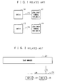
- FIG. 1 shows an example of the monitor control system of this type.
Unit A 10 andunit B 13, which are to be monitored, are connected respectively viacables local craft terminals - Third, the monitor control system does not include the function to convert an alarm signal of the unit into an SNMP alarm signal. This is because manager software has not been the SNMP manager.
- Fourth, if a different type of a monitor target unit is installed, it is necessary for the conventional monitor control system to add a large-sized function to its software for the following reason. The local craft terminal used to be employed as a single unit and hence is not used as one module in the monitor control system.
- Fifth, the SNMP manager is adopted as a single device and can display an alarm state of the monitor target unit, but cannot conduct operations such as a control operation and an alteration of settings for the monitor target unit. This is because there does not exist a function in which the SNMP manager and the local craft terminal are installed in one personal computer and are mutually connected to each other.
- FIG. 2 shows an example of such monitor control system. In the example, an
SNMP manager 21 is coupled via a Local Area Network (LAN) to unitA 22 andunit B 23. In this example, only the SNMPmanager 21 is used and only the alarm display is done. In the configuration, although categorized alarms can be displayed, but the monitor control, the operation, and the setting cannot be carried out for the unit.Japanese Patent Application Laid-Open Ser. No. 2004-086522 - An exemplary object of the invention is to provide a monitor control system, an information processing terminal, a monitor control method, and a program that are economically advantageously implemented by using inexpensive modules such as a personal computer, an SNMP manager, and a local craft terminal not requiring high technical knowledge; that are easily operable without particular experiences and are easily expandable using additional unit types of monitor target units; and that are operable at a remote place.
- In accordance with an exemplary aspect of the present invention, there is provided a monitor control system including at least one monitor target unit that is monitored, and a monitor controller that is connected via a network to the monitor target unit and controls the monitor target unit, the controller conducting monitor control, operation, and setting for the monitor target unit by use of a Simple Network Management Protocol (SNMP). The monitor controller includes an SNMP mediator that receives an alarm signal from a monitor target unit in which an alarm has occurred and converts the alarm signal into an SNMP alarm signal, an SNMP manager that receives an SNMP alarm signal from the SNMP mediator or a monitor target unit in which an alarm has occurred and displays the alarm according to the SNMP alarm signal, at least one local craft terminal, corresponding to monitor target units, that logs into monitor target units, and an application initiating module that activates, when an operation is conducted to designate a predetermined monitor target unit, a local craft terminal associated with the monitor target unit.
- In accordance with another exemplary aspect the present invention, there is provided an information processing terminal employed in the monitor control system.
- In accordance with another exemplary aspect of the present invention, there is provided a monitor control method of conducting monitor control, operation, and setting for at least one monitor target unit arranged on a network, by use of an SNMP. The method includes an SNMP alarm signal acquiring step of receiving an SNMP alarm signal directly from the monitor target unit or receiving an alarm signal from the monitor target unit and converting the alarm signal into an SNMP alarm signal, an alarm display step of displaying the alarm according to the SNMP alarm signal, an application initiating step of activating, when an operation is conducted to designate a predetermined monitor target unit, a local craft terminal corresponding to the monitor target unit, and a monitor target unit control step of logging into the monitor target unit by use of the local craft terminal and conducting monitor control, operation, and setting for the monitor target unit.
- In accordance with another exemplary aspect of the present invention, there is provided a computer program product for conducting monitor control, operation, and setting for at least one monitor target unit arranged on a network, by use of an SNMP. At occurrence of an alarm in the monitor target unit, the program causes a computer to perform SNMP alarm signal acquiring processing for receiving an SNMP alarm signal directly from the monitor target unit or receiving an alarm signal from the monitor target unit and converting the alarm signal into an SNMP alarm signal, alarm display processing for displaying the alarm according to the SNMP alarm signal, application initiating processing for activating, when an operation is conducted to designate a predetermined monitor target unit, a local craft terminal corresponding to the monitor target unit, and monitor target unit control processing for logging into the monitor target unit by use of the local craft terminal and conducting monitor control, operation, and setting for the monitor target unit.
- Features of the disclosed embodiments will be described by way of the following detailed description with reference to the accompanying drawings in which:
- FIG. 1 is a block diagram showing an example of a configuration of cable connections in a conventional monitor control system;
- FIG. 2 is a block diagram showing an example of the structure using only the SNMP manager in a conventional monitor control system;
- FIG. 3 is a schematic block diagram showing a configuration of a monitor control system and a monitor controller;
- FIG. 4 is a flowchart showing operation of the monitor controller;
- FIG. 5 is a block diagram showing structure of a monitor control system and a monitor controller; and
- FIG. 6 is a flowchart showing operation of the monitor controller.
- Referring next to the accompanying drawings, description will be given in detail of exemplary embodiments.
- FIG. 3 shows a configuration of a monitor control system and a monitor controller.
- The system includes a monitor controller 1 and a
unit A 8 and aunit B 7, and a Local Area Network (LAN) 9 connecting the controller 1 and the units A and B to each other as shown in FIG. 3. Theunit A 8 and theunit B 7 are installed at remote locations as monitor target units to be monitored by the controller 1. - In FIG. 3, the monitor controller (network management system) 1 is one personal computer (information processing terminal). The controller 1 includes an
SNMP manager 2, an SNMP mediator 3,local craft terminals - The
SNMP manager 2 of FIG. 3 directly receives an SNMP alarm signal from a monitor target unit in which an alarm has occurred. The SNMP mediator 3 converts into a SNMP alarm signal an alarm signal sent from a monitor target unit. Themanager 2 receives the SNMP alarm signal. According to the SNMP alarm signal, themanager 2 displays information items such as an alarm name and a category of the alarm on a screen of the monitor controller 1. - In the configuration of FIG. 3, the SNMP mediator 3 converts an alarm signal from a monitor target unit that cannot produce an SNMP alarm signal into an SNMP alarm signal.
- The
local craft terminal 4 of FIG. 3 logs into theunit B 7 arranged as a monitor target unit in a remote place and carries out the control operation, the setting change, and the like for theunit B 7. The local craft terminal is application software inherently and directly coupled with the monitor target unit to conduct operations for the target unit such as a monitor control, an operation, and the setting for the target unit. The monitor control, the operation, and the setting for the monitor target unit are not possible without a local craft terminal. Therefore, the local craft terminal is ordinarily designed together with the monitor target unit. - In FIG. 3, the
local craft terminal 5 conducts a login operation for theunit A 8 as a monitor target unit in a remote place and achieves the control operation, the setting change, and the like for theunit A 8. The local craft terminal is application software that is to be directly connected to the monitor target unit to carry out operations for the target unit, for example, the monitor control, the operation, and the setting for the target unit. The monitor control, the operation, and the setting for the target unit are possible only when the local craft terminal is present. Therefore, ordinarily, the local craft terminal is designed together with the monitor target unit. - The application initiating module 6 includes a function to detect an operation conducted by the operator of the monitor controller 1 to designate an inspection target unit, i.e., a monitor target unit in which an alarm has taken place (or of which an operation state is to be examined) to resultantly activate the
local craft terminal - The
SNMP manager 2 is well known to those skilled in the art and hence description of detailed structure thereof will be avoided. - FIG. 4 shows an operation of the monitor controller in a flowchart. The controller conducts the processing (a monitor control method) under the control of a program.
- In step S1 of FIG. 4, it is assumed that an alarm occurs, for example, in the
unit B 7, i.e., a monitor target unit shown in FIG. 3. Each of the units A and B includes a function to automatically send an alarm signal to an external device at occurrence of an alarm. The alarm signal includes a text message indicating an alarm's name and category information indicating a categorized degree of importance of the alarm such as "major", "minor", or "warning". - In step S2, the unit B in which an alarm has occurred transmits, if possible (yes in step S2), an SNMP alarm signal via the
LAN 9 to theSNMP manager 2. If the unit B cannot send the alarm signal (no in step S2), the signal is delivered to a SNMP mediator task. - In step S3, the mediator 3 receives the alarm signal and converts the signal into an SNMP alarm signal to feed the signal to the
SNMP manager 2. - The SNMP alarm signal sent in step S2 or S3 is received by the
manager 2 in step S4. On the basis of the received signal including a text message indicating an alarm name and category information indicating the category of the alarm, themanager 2 displays associated information on the screen of the monitor controller 1. Specifically, themanager 2 displays a text of the alarm name, an icon indicating theunit B 7, and a network diagram showing connections between the units. According to the category of the alarm, the icon of the associated unit, i.e., theunit B 7 is displayed, for example, in red for "major", pink for "minor", and yellow for "warning". In the state of step S4, the operator of the monitor controller 1 can recognize only the category and the alarm name of the alarm automatically displayed on the screen. - In step S5, to examine details of the alarm, the operator conducts an operation to specify the device, i.e., the unit B, for example, by clicking the icon of the unit B on the screen. Thereafter, the application initiating section 6 detects the operation, activates the
local craft terminal 4 associated with the unit B, and then logs via theLAN 9 into the unit B using, for example, an IP address. - In step S7, by use of the
local craft terminal 4 having logged into the unit B via theLAN 9, the operator of the monitor controller 1 is able to obtain alarm information indicating details of the alarm and carry out the monitor control, the operation or maintenance, and the setting change for the unit B. The operations achievable by the task such as the monitor control, the operation, and the setting change for the unit are substantially equal to those feasible at the installation site of the single-unit local craft terminal according to the conventional technique as shown in FIG. 1. That is, operation items are not restricted and hence the operations allowed according to the specifications of the device are available. - In
step 8, the alarm information, data associated with operation of the monitor controller, and data related to the operator of the controller are accumulated in a storage module of the monitor controller 1. - In a situation other than the inspection at occurrence of an alarm, for example, in a situation where it is required for the operator of the monitor controller 1 to carry out the monitor control, the operation, or the setting change for the monitor target unit, if the operator designates a predetermined monitor target unit in step S6 of FIG. 4, the application initiating module 6 activates the local craft terminal of the designated target unit. As a result, by use of the craft terminal, it is possible to log into the unit via the
LAN 9 using an IP address or the like. - The embodiment described above includes local craft terminals for various types of monitor target units. Therefore, the monitor control, the operation, and the setting can be conducted for the monitor target units of various types. By increasing the types of local craft terminals, the types of monitor target units can be increased.
- Additionally, since the embodiment also includes the SNMP mediator, the monitor control can be carried out for monitor target units that cannot transmit the SNMP alarm signal.
- According to the embodiment, there can be obtained advantages as below.
- First, an alarm of a monitor target unit at a remote location can be automatically displayed. The reason is that with the SNMP manager, the monitor control system is connected via a LAN to the monitor target unit.
- Second, even if the monitor target unit cannot send an SNMP alarm signal, an alarm of the unit can be monitored. The SNMP mediator converts an alarm signal from the target unit into an SNMP alarm signal and sends the signal to the SNMP manager.
- Third, it is possible to log into the monitor target unit at a remote place. The application initiating function activates the associated local craft terminal. It is therefore possible to log into the target unit via a LAN by use of an IP address or the like of the unit.
- Fourth, the operations required for the monitor target unit such as the monitor control, the operation, and the setting can be carried out at a remote place. By using the local craft terminal for the target unit, it is possible to log into the target unit via a LAN.
- In the first embodiment, if it is required that a monitor target unit continuously occupy a particular software port of the SNMP manager for a predetermined period of time to conduct, for example, the monitor control setting operation, the monitor controller allows the unit to occupy the software port. During the period of time in which the unit is allowed to occupy the software port, the controller successively receives SNMP traps from another monitor target unit. However, while a particular software port is being occupied, the SNMP manager cannot receive an SNMP trap sent from another monitor target unit to the software port thus occupied. This consequently leads to a problem that the information of the SNMP manager is not successively updated to the latest information.
- To cope with the problem, the monitor controller of the second embodiment includes an SNMP software port conversion function. Thanks to the function that executes SNMP software port conversion processing, during the period of time in which a monitor target unit occupies a particular software port and the port cannot receive a signal, an SNMP trap sent from another monitor target unit to the software port is delivered to be received by the SNMP manager by use of an empty port that can receive a signal. Resultantly, it is guaranteed that the information possessed by the SNMP manager is continuously updated by the latest SNMP trap in any situation.
- FIG. 5 shows structure of a monitor control system and a monitor controller. In FIG. 5, the same constituent components as those of FIG. 3 are assigned with the same reference numerals, and description thereof will be avoided.
- In FIG. 5, if a monitor target unit occupies a particular software port of the SNMP manager continuously for a predetermined period of time, for example, to conduct the monitor control setting operation, the SNMP software
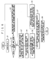
port conversion module 17 makes it possible to continuously receive an SNMP trap from another monitor target unit even while the particular software port is being occupied. That is, the module transfers the SNMP trap, which is addressed to the software port being occupied as above, to the SNMP manager via an empty port. - FIG. 6 shows operation of the monitor controller of the second embodiment. The controller carries out processing (of a monitor control method) under the control of a program.
- Assume in step S1 of FIG. 6 that an alarm occurs in, for example,
unit B 7 as a monitor target unit shown in FIG. 5. Each of the units A and B includes a function to automatically deliver an alarm signal to an external device at occurrence of an alarm. The alarm signal includes a text message indicating the alarm name and category information indicating importance of the alarm, for example, "major", "minor", or "warning". - In step S2 of FIG. 6, if the
unit B 7 in which the alarm has occurred can deliver an SNMP alarm signal (yes in step S2), the signal is sent via theLAN 9 to theconversion module 17. If theunit B 7 cannot transmit the SNMP alarm signal (no in step S2), an alarm signal is fed to a SNMP mediator task. - In step S3, when the alarm signal from the
unit B 7 is received, the SNMP mediator 3 converts the signal into an SNMP alarm signal to send the alarm signal to theconversion module 17. - In step S3' of FIG. 6, the
conversion module 17 determines whether the destination of the SNMP alarm signal is a software port of theSNMP manager 2 in a signal receivable state. If the software port is in a signal receivable state, the SNMP alarm signal is delivered thereto. If the software port is occupied by another unit and is in a signal unreceivable state, theconversion function 17 selects an empty port capable of receiving the SNMP alarm signal and transmits the signal to theSNMP manager 2 by using the empty port. - The processing flow after step S4 is substantially equal to that described for the first embodiment by referring to FIG. 4, and hence description thereof will be omitted.
- In accordance with the second embodiment, advantageous aspects are as follows.
- The monitor controller can continuously display the latest alarm information of the monitor target unit in any case for the following reason. Due to the SNMP software port conversion function, the monitor controller can successively receive the latest alarm information of the monitor target unit. In this way, the monitor controller can display the latest alarm information in any situation.
- In the monitor control system, the monitor target unit may send the SNMP alarm signal directly to the SNMP manager if the unit includes a function to transmit the SNMP alarm signal. Otherwise the monitor target unit may send the alarm signal to the SNMP mediator.
- In the monitor control system, the SNMP alarm signal may include a category and a name of the alarm having occurred in the monitor target unit, and the SNMP manager may display, at reception of the SNMP alarm signal, the category and the name of the alarm according to the SNMP alarm signal.
- In the monitor control system, the SNMP manager may display a network diagram indicating a relation of connections between units on the network and an icon in the diagram to indicate the monitor target unit in which the alarm has occurred, the icon being displayed in colors corresponding to the category of the alarm.
- The monitor control system may further include an SNMP software port conversion module that relays an SNMP alarm signal transmitted to the SNMP manager, determines, if a software port as a destination of the SNMP alarm signal is occupied by another monitor target unit and hence cannot receive the SNMP alarm signal, an empty port capable of receiving the SNMP alarm signal, and transmits the SNMP alarm signal via the empty port to the SNMP manager.
- In the monitor control method, the SNMP alarm signal may include a category and a name of the alarm having occurred in the monitor target unit. The alarm display step may include displaying the category and the name of the alarm having occurred in the monitor target unit, according to the SNMP alarm signal.
- In the monitor control method, the alarm display step may include displaying a network diagram indicating a relation of connections between units arranged on the network and an icon in the diagram to indicate the monitor target unit in which the alarm has occurred, the icon being displayed in colors corresponding to the category of the alarm.
- The monitor control method may further include an SNMP software port conversion step of relaying an SNMP alarm signal transmitted to the SNMP manager, determining, if a software port as a destination of the SNMP alarm signal is occupied by a second monitor target unit and hence cannot receive the SNMP alarm signal, an empty port capable of receiving the SNMP alarm signal, and transmitting the SNMP alarm signal via the empty port to the SNMP manager.
- According to a computer program product, the SNMP alarm signal may include a category and a name of the alarm having occurred in the monitor target unit and the program causes a computer to perform, as the alarm display processing, processing to display the category and the name of the alarm having occurred in the monitor target unit, according to the SNMP alarm signal.
- The program may cause a computer to perform processing to display a network diagram indicating a relation of connections between units on the network and an icon in the diagram to indicate the monitor target unit in which the alarm has occurred, the icon being displayed in a color changed according to the category of the alarm.
- The program may cause a computer to perform SNMP software port conversion processing for relaying an SNMP alarm signal transmitted to the SNMP manager, determining, if a software port as a destination of the SNMP alarm signal is occupied by another monitor target unit and hence cannot receive the SNMP alarm signal, an empty port capable of receiving the SNMP alarm signal, and transmitting the SNMP alarm signal via the empty port to the SNMP manager.
- The present invention is applicable to the control operation to monitor, to operate, and to install a monitor target unit at a remote place.
- An exemplary advantage according to the invention is that it is possible to implement a monitor control system, an information processing terminal, a monitor control method, and a program that are economically advantageously implemented and are easily operable without particular experiences and which are easily expandable using additional unit types of monitor target units and are operable at a remote place.
- While the present invention has been described with reference to the particular illustrative embodiment, it is not to be restricted by those embodiments but only by the appended claims. It is to be appreciated that those skilled in the art can change or modify the embodiment without departing from the scope and spirit of the present invention.
Claims (14)
- A monitor control system, comprising:at least one monitor target unit that is monitored; anda monitor controller that is connected via a network to a monitor target unit and controls the monitor target unit, the controller conducting monitor control, operation, and setting for the monitor target unit by use of a Simple Network Management Protocol (SNMP), wherein the monitor controller comprises:an SNMP mediator that receives an alarm signal from a monitor target unit in which an alarm has occurred and converts the alarm signal into an SNMP alarm signal;an SNMP manager that receives an SNMP alarm signal from the SNMP mediator or a monitor target unit in which an alarm has occurred and displays the alarm according to the SNMP alarm signal;at least one local craft terminal, corresponding to monitor target units, that logs into monitor target units andan application initiating module that activates, when an operation is conducted to designate a predetermined monitor target unit, a local craft terminal associated with the monitor target unit.
- The monitor control system in accordance with claim 1, wherein:the monitor target unit sends the SNMP alarm signal directly to the SNMP manager if the unit includes a function to transmit the SNMP alarm signal,; andthe monitor target unit sends the alarm signal to the SNMP mediator if the unit does not include a function to transmit the SNMP alarm signal,.
- The monitor control system in accordance with claim 1 or 2, wherein:the SNMP alarm signal includes a category and a name of the alarm having occurred in the monitor target unit; andthe SNMP manager displays, upon reception of the SNMP alarm signal, the category and the name of the alarm according to the SNMP alarm signal.
- The monitor control system in accordance with any one of claims 1 to 3, wherein the SNMP manager displays a network diagram indicating a relation of connections between units on the network and an icon in the diagram to indicate the monitor target unit in which the alarm has occurred, the icon being displayed in colors corresponding to the category of the alarm.
- The monitor control system in accordance with any one of claims 1 to 4, further comprising an SNMP software port conversion module that relays an SNMP alarm signal transmitted to the SNMP manager, determines, if a software port as a destination of the SNMP alarm signal is occupied by another monitor target unit and hence cannot receive the SNMP alarm signal, an empty port capable of receiving the SNMP alarm signal, and transmits the SNMP alarm signal via the empty port to the SNMP manager.
- An information processing terminal employed as a monitor controller in a monitor control system in accordance with one of claims 1 to 5.
- A monitor control method of conducting by use of an SNMP monitor control, operation, and setting for at least one monitor target unit arranged on a network, the method comprising:an SNMP alarm signal acquiring step of receiving an SNMP alarm signal directly from a monitor target unit that issued an alarm or receiving an alarm signal from the monitor target unit, and converting the alarm signal into an SNMP alarm signal;an alarm display step of displaying the alarm according to the SNMP alarm signal;an application initiating step of activating, when an operation is conducted to designate a predetermined monitor target unit, a local craft terminal corresponding to the monitor target unit; anda monitor target unit control step of logging into the monitor target unit by use of the local craft terminal and conducting monitor control, operation, and setting for the monitor target unit.
- The monitor control method in accordance with claim 7, wherein:the SNMP alarm signal includes a category and a name of the alarm; andthe alarm display step comprises displaying the category and the name of the alarm according to the SNMP alarm signal.
- The monitor control method in accordance with claim 7 or 8, wherein the alarm display step comprising displaying a network diagram indicating a relation of connections between units arrange on the network and an icon in the diagram to indicate the monitor target unit in which the alarm has occurred, the icon being displayed in colors corresponding to the category of the alarm.
- The monitor control method in accordance with any one of claims 7 to 9, further comprising an SNMP software port conversion step of relaying an SNMP alarm signal transmitted to the SNMP manager, determining, if a software port as a destination of the SNMP alarm signal is occupied by another monitor target unit and hence cannot receive the SNMP alarm signal, an empty port capable of receiving the SNMP alarm signal, and transmitting the SNMP alarm signal via the empty port to the SNMP manager.
- A computer program product for conducting by use of an SNMP monitor control, operation, and setting for at least one monitor target unit arranged on a network, the program causing a computer to perform:SNMP alarm signal acquiring processing for receiving an SNMP alarm signal directly from a monitor target unit that issued an alarm or receiving an alarm signal from the monitor target unit, and converting the alarm signal into an SNMP alarm signal;alarm display processing for displaying the alarm according to the SNMP alarm signal;application initiating processing for activating, when an operation is conducted to designate a predetermined monitor target unit, a local craft terminal corresponding to the monitor target unit; andmonitor target unit control processing for logging into the monitor target unit by use of the local craft terminal and conducting monitor control, operation, and setting for the monitor target unit.
- The computer program product in accordance with claim 11, wherein the SNMP alarm signal includes a category and a name of the alarm,
and the program further causing a computer to perform processing of displaying the category and the name of the alarm according to the SNMP alarm signal. - The computer program product in accordance with claim 11 or 12, the program causing a computer to perform processing of displaying a network diagram indicating a relation of connections between units on the network and an icon in the diagram to indicate the monitor target unit in which the alarm has occurred, the icon being displayed in colors corresponding to the category of the alarm.
- The computer program product in accordance with any one of claims 11 to 13, the program causing a computer to perform SNMP software port conversion processing for relaying an SNMP alarm signal transmitted to the SNMP manager, determining, if a software port as a destination of the SNMP alarm signal is occupied by another monitor target unit and hence cannot receive the SNMP alarm signal, an empty port capable of receiving the SNMP alarm signal, and transmitting the SNMP alarm signal via the empty port to the SNMP manager.
Applications Claiming Priority (2)
| Application Number | Priority Date | Filing Date | Title |
|---|---|---|---|
| JP2006148778A JP2007318677A (en) | 2006-05-29 | 2006-05-29 | Supervisory and control system, information processing terminal device, supervisory and control method and program |
| JP2007108515A JP2008269092A (en) | 2007-04-17 | 2007-04-17 | Monitor control system, information processing terminal, monitor control method, and program |
Publications (2)
| Publication Number | Publication Date |
|---|---|
| EP1863224A2 true EP1863224A2 (en) | 2007-12-05 |
| EP1863224A3 EP1863224A3 (en) | 2008-09-24 |
Family
ID=38616247
Family Applications (1)
| Application Number | Title | Priority Date | Filing Date |
|---|---|---|---|
| EP07252107A Withdrawn EP1863224A3 (en) | 2006-05-29 | 2007-05-22 | Monitor control system, information processing terminal, monitor control method and program |
Country Status (2)
| Country | Link |
|---|---|
| US (1) | US20070288631A1 (en) |
| EP (1) | EP1863224A3 (en) |
Citations (3)
| Publication number | Priority date | Publication date | Assignee | Title |
|---|---|---|---|---|
| EP0963076A2 (en) | 1998-05-31 | 1999-12-08 | Lucent Technologies Inc. | Method for computer internet remote management of a telecommunication network element |
| US6539422B1 (en) | 1998-05-04 | 2003-03-25 | Intermec Ip Corp. | Automatic data collection device having a network communications capability |
| JP2004086522A (en) | 2002-08-27 | 2004-03-18 | Fujitsu Access Ltd | Communication network monitoring system |
Family Cites Families (9)
| Publication number | Priority date | Publication date | Assignee | Title |
|---|---|---|---|---|
| US5740368A (en) * | 1995-06-30 | 1998-04-14 | Canon Kabushiki Kaisha | Method and apparatus for providing information on a managed peripheral device to plural agents |
| JP3617770B2 (en) * | 1998-05-29 | 2005-02-09 | 株式会社日立製作所 | Network management system and network management method |
| JP3886309B2 (en) * | 1999-11-16 | 2007-02-28 | 日本電気株式会社 | Network management system and network management method |
| US6754705B2 (en) * | 2001-12-21 | 2004-06-22 | Networks Associates Technology, Inc. | Enterprise network analyzer architecture framework |
| US20050108486A1 (en) * | 2003-08-05 | 2005-05-19 | Miklos Sandorfi | Emulated storage system supporting instant volume restore |
| US8701175B2 (en) * | 2005-03-01 | 2014-04-15 | Tavve Software Company | Methods, devices, systems and computer program products for providing secure communications between managed devices in firewall protected areas and networks segregated therefrom |
| JP2006268205A (en) * | 2005-03-23 | 2006-10-05 | Fujitsu Ltd | Monitor device for network equipment where snmp interface is not available |
| US8244844B2 (en) * | 2006-03-17 | 2012-08-14 | Samsung Electronics Co., Ltd. | Tool for data generation for simple network management protocol (SNMP) |
| US20070220157A1 (en) * | 2006-03-17 | 2007-09-20 | Samsung Electronics Co., Ltd. | Simple network management protocol (SNMP) agent system and method |
-
2007
- 2007-05-22 EP EP07252107A patent/EP1863224A3/en not_active Withdrawn
- 2007-05-25 US US11/802,919 patent/US20070288631A1/en not_active Abandoned
Patent Citations (3)
| Publication number | Priority date | Publication date | Assignee | Title |
|---|---|---|---|---|
| US6539422B1 (en) | 1998-05-04 | 2003-03-25 | Intermec Ip Corp. | Automatic data collection device having a network communications capability |
| EP0963076A2 (en) | 1998-05-31 | 1999-12-08 | Lucent Technologies Inc. | Method for computer internet remote management of a telecommunication network element |
| JP2004086522A (en) | 2002-08-27 | 2004-03-18 | Fujitsu Access Ltd | Communication network monitoring system |
Non-Patent Citations (1)
| Title |
|---|
| G.H. AICKLEN; P.M. MAIN: "Remote Control of Diverse Network Elements Using SNMP", 5 November 1995, IEEE, pages: 673 - 677 |
Also Published As
| Publication number | Publication date |
|---|---|
| US20070288631A1 (en) | 2007-12-13 |
| EP1863224A3 (en) | 2008-09-24 |
Similar Documents
| Publication | Publication Date | Title |
|---|---|---|
| US4847837A (en) | Local area network with fault-checking, priorities and redundant backup | |
| JPH02182057A (en) | Network management system | |
| US20030139820A1 (en) | Plant operating apparatus and method | |
| JPH10187498A (en) | Fault information system | |
| EP1863224A2 (en) | Monitor control system, information processing terminal, monitor control method and program | |
| US20130054676A1 (en) | Computer network based hazardous condition monitoring system and server | |
| WO2015199285A1 (en) | System for configuring reference information of system monitoring and predicting abnormality of smt manufacturing line, and control method therefor | |
| JP4965239B2 (en) | Remote monitoring system | |
| CN113009246B (en) | PSE device detection device and PSE device detection method | |
| JP2008269092A (en) | Monitor control system, information processing terminal, monitor control method, and program | |
| JPH06266635A (en) | Network resource monitor system | |
| JPH10326395A (en) | Disaster preventive centralized monitor and control system | |
| JP2007318677A (en) | Supervisory and control system, information processing terminal device, supervisory and control method and program | |
| JP2008242951A (en) | Monitoring system for digital protection relay | |
| US20050088526A1 (en) | Remote audio controlling system and method | |
| JP2007189435A (en) | Monitoring device | |
| JP3336214B2 (en) | Building remote management device | |
| JP2004206598A (en) | Alarm monitoring system | |
| KR100416044B1 (en) | Method of Managing System State Information in the Manager's Interface System | |
| JPH10107792A (en) | Server monitor | |
| KR100244780B1 (en) | The method for system management using i2c bus | |
| CN115665122A (en) | Special interface arrangement of transformer substation's fire control host computer network deployment | |
| JPH09130414A (en) | Network management system | |
| JPH11283167A (en) | Transmission line disconnection compensator and tunnel disaster prevention system | |
| CN114140969A (en) | Fire-fighting management system |
Legal Events
| Date | Code | Title | Description |
|---|---|---|---|
| PUAI | Public reference made under article 153(3) epc to a published international application that has entered the european phase |
Free format text: ORIGINAL CODE: 0009012 |
|
| AK | Designated contracting states |
Kind code of ref document: A2 Designated state(s): AT BE BG CH CY CZ DE DK EE ES FI FR GB GR HU IE IS IT LI LT LU LV MC MT NL PL PT RO SE SI SK TR |
|
| AX | Request for extension of the european patent |
Extension state: AL BA HR MK YU |
|
| PUAL | Search report despatched |
Free format text: ORIGINAL CODE: 0009013 |
|
| AK | Designated contracting states |
Kind code of ref document: A3 Designated state(s): AT BE BG CH CY CZ DE DK EE ES FI FR GB GR HU IE IS IT LI LT LU LV MC MT NL PL PT RO SE SI SK TR |
|
| AX | Request for extension of the european patent |
Extension state: AL BA HR MK RS |
|
| 17P | Request for examination filed |
Effective date: 20090112 |
|
| 17Q | First examination report despatched |
Effective date: 20090319 |
|
| AKX | Designation fees paid |
Designated state(s): FR GB |
|
| REG | Reference to a national code |
Ref country code: DE Ref legal event code: 8566 |
|
| STAA | Information on the status of an ep patent application or granted ep patent |
Free format text: STATUS: THE APPLICATION HAS BEEN WITHDRAWN |
|
| 18W | Application withdrawn |
Effective date: 20100616 |