EP1864483B1 - Automatic audio and video synchronization - Google Patents
Automatic audio and video synchronization Download PDFInfo
- Publication number
- EP1864483B1 EP1864483B1 EP06727417A EP06727417A EP1864483B1 EP 1864483 B1 EP1864483 B1 EP 1864483B1 EP 06727417 A EP06727417 A EP 06727417A EP 06727417 A EP06727417 A EP 06727417A EP 1864483 B1 EP1864483 B1 EP 1864483B1
- Authority
- EP
- European Patent Office
- Prior art keywords
- video
- audio
- master
- signal
- slave devices
- Prior art date
- Legal status (The legal status is an assumption and is not a legal conclusion. Google has not performed a legal analysis and makes no representation as to the accuracy of the status listed.)
- Expired - Fee Related
Links
Images
Classifications
-
- H—ELECTRICITY
- H04—ELECTRIC COMMUNICATION TECHNIQUE
- H04N—PICTORIAL COMMUNICATION, e.g. TELEVISION
- H04N5/00—Details of television systems
- H04N5/04—Synchronising
-
- H—ELECTRICITY
- H04—ELECTRIC COMMUNICATION TECHNIQUE
- H04N—PICTORIAL COMMUNICATION, e.g. TELEVISION
- H04N21/00—Selective content distribution, e.g. interactive television or video on demand [VOD]
- H04N21/40—Client devices specifically adapted for the reception of or interaction with content, e.g. set-top-box [STB]; Operations thereof
- H04N21/43—Processing of content or additional data, e.g. demultiplexing additional data from a digital video stream; Elementary client operations, e.g. monitoring of home network or synchronising decoder's clock; Client middleware
- H04N21/4302—Content synchronisation processes, e.g. decoder synchronisation
- H04N21/4307—Synchronising the rendering of multiple content streams or additional data on devices, e.g. synchronisation of audio on a mobile phone with the video output on the TV screen
- H04N21/43072—Synchronising the rendering of multiple content streams or additional data on devices, e.g. synchronisation of audio on a mobile phone with the video output on the TV screen of multiple content streams on the same device
-
- H—ELECTRICITY
- H04—ELECTRIC COMMUNICATION TECHNIQUE
- H04N—PICTORIAL COMMUNICATION, e.g. TELEVISION
- H04N21/00—Selective content distribution, e.g. interactive television or video on demand [VOD]
- H04N21/40—Client devices specifically adapted for the reception of or interaction with content, e.g. set-top-box [STB]; Operations thereof
- H04N21/43—Processing of content or additional data, e.g. demultiplexing additional data from a digital video stream; Elementary client operations, e.g. monitoring of home network or synchronising decoder's clock; Client middleware
- H04N21/436—Interfacing a local distribution network, e.g. communicating with another STB or one or more peripheral devices inside the home
- H04N21/4363—Adapting the video or multiplex stream to a specific local network, e.g. a IEEE 1394 or Bluetooth® network
-
- H—ELECTRICITY
- H04—ELECTRIC COMMUNICATION TECHNIQUE
- H04N—PICTORIAL COMMUNICATION, e.g. TELEVISION
- H04N21/00—Selective content distribution, e.g. interactive television or video on demand [VOD]
- H04N21/40—Client devices specifically adapted for the reception of or interaction with content, e.g. set-top-box [STB]; Operations thereof
- H04N21/45—Management operations performed by the client for facilitating the reception of or the interaction with the content or administrating data related to the end-user or to the client device itself, e.g. learning user preferences for recommending movies, resolving scheduling conflicts
- H04N21/462—Content or additional data management, e.g. creating a master electronic program guide from data received from the Internet and a Head-end, controlling the complexity of a video stream by scaling the resolution or bit-rate based on the client capabilities
- H04N21/4622—Retrieving content or additional data from different sources, e.g. from a broadcast channel and the Internet
-
- H—ELECTRICITY
- H04—ELECTRIC COMMUNICATION TECHNIQUE
- H04N—PICTORIAL COMMUNICATION, e.g. TELEVISION
- H04N5/00—Details of television systems
- H04N5/44—Receiver circuitry for the reception of television signals according to analogue transmission standards
- H04N5/60—Receiver circuitry for the reception of television signals according to analogue transmission standards for the sound signals
- H04N5/602—Receiver circuitry for the reception of television signals according to analogue transmission standards for the sound signals for digital sound signals
-
- H—ELECTRICITY
- H04—ELECTRIC COMMUNICATION TECHNIQUE
- H04N—PICTORIAL COMMUNICATION, e.g. TELEVISION
- H04N7/00—Television systems
- H04N7/01—Conversion of standards, e.g. involving analogue television standards or digital television standards processed at pixel level
- H04N7/0117—Conversion of standards, e.g. involving analogue television standards or digital television standards processed at pixel level involving conversion of the spatial resolution of the incoming video signal
- H04N7/012—Conversion between an interlaced and a progressive signal
Definitions
- the present invention relates generally to synchronizing audio and video and more specifically to automatically synchronizing audio and video output in a multi-component multi-media processing system.
- a first group of processing elements may be utilized to generate a video signal and a second group of processing elements may be utilized to generate an audio signal.
- a second group of processing elements may be utilized to generate an audio signal.
- a separate audio subsystem must be utilized, such as a surround sound system integrated within an existing viewing area, such as a living room.
- FIG. 1 illustrates a graphical representation of a prior art audio and video processing system 100.
- the system includes a source device 102, such as any suitable source for generating an incoming signal.
- the source may be a digital versatile disk (DVD) player, a digital video recording device, or any other suitable device capable of reading audio and video information off of a stored medium.
- DVD digital versatile disk
- other input sources such as a satellite receiver 104 or a cable receiver 106 may also be utilized to receive incoming audio and video signals.
- a video receiver 108 is operative to receive a video signal 110 from at least one of the various sources, such as the exemplary sources of the video source 102, satellite receiver 104 or cable receiver 106.
- the video receiver 108 may perform image processing operations to generate an output video signal 112 which is provided to a video display 114, such as a standard television.
- the system 100 further includes an audio receiver 116 which is operative to receive an audio signal 118 from at least one of the different sources, such as the video source 102, satellite receiver 104 and cable receiver 106.
- the audio receiver 116 may be any suitable audio receiving device capable of receiving the incoming audio signal and performing signal processing to generate an output audio signal 120 to an audio output device or devices 122, such as speakers, 122.
- the prior art approach for synchronizing the video signal 112 and the audio signal 120 to the video display 114 and corresponding audio output devices 122, respectively, is manual configuration.
- a technician manually utilizes a testing device 124.
- the testing device may be any suitable processing device capable of receiving the video signal 112 and the audio signal 120.
- the testing device 124 is operative to determine a delay interval between a particular frame of video data 112 with a corresponding audio portion 120. Based on this calculated delay, the testing device then generates a delay signal 126 which is provided to a display for allowing manual adjustment 128.
- FIG. 1 illustrates functional block 128 for manual adjustment, but as recognized by one having ordinary skill in the art, functional block 128 represents a physical action to be performed by a technician for manually adjusting a corresponding offset amount 130 within the audio receiver 116. Therefore, due to utilization of a technician and manual adjustment 128 of an offset amount 130 based on the detected offset 126 from the testing device 124, the audio receiver 116 may be tweaked to align the audio output to the video output.
- the current approach for synchronizing audio and video output requires manual adjustment 128 of the audio receiver 116 corresponding to delay within the video receiver 108. Not only does this approach require a technician or technically advanced user to manually adjust the audio receiver 116, the present approach is only operative for the configuration of the video receiver 108.
- a television set top box is in communication with a first home computer and a second home computer
- different processing resources may be utilized between different computers and the set top box to allow for maximizing available processing resources and generating the best possible video output.
- the audio receiver such as the audio receiver 116.
- Current techniques do not allow for automatic adjustment of timing sequences for synchronizing audio and video output. Therefore, there exists a need for improving synchronization of audio and video output signals in a networking environment.
- European patent applications EP 1 067 773 A and EP 1 104 179 A disclose a method and apparatus for automatic audio and video output synchronization, wherein a video delay time period is calculated based on a signal processing routine to generate the video display signal.
- the present invention provides for automatic audio and video synchronization by calculating a video delay time period based on a signal processing routine to generate the video display signal and automatically setting an audio delay to approximate the video delay time period.
- the method may include if desired, determining a master device from a plurality of master capable devices.
- the master device is a processing device including one or more processors capable of making configuration decisions and designating a data flow for rendering a video signal.
- the master-capable devices are any suitable processing devices which are capable of acting as a master device.
- the present invention may further include using the master device to determine a signal processing routine to generate a video display signal.
- the signal processing routine includes a designated data flow from one processing element to a next processing element to a next processing element and so on for different stages of video signal rendering.
- the video delay time period may be calculated based on the delay of an incoming video signal and the signal being provided to all of the different processing devices until the generation of a subsequent video output signal. Furthermore, the present invention includes using the master device to automatically set an audio delay in an audio processing device to a time period approximate to the video delay time period.
- the audio processing device may be any suitable audio processor capable of receiving an incoming audio signal and thereupon generating a corresponding audio output signal for an audio display, such as a plurality of speakers.
- the present invention allows for the automatic adjustment of audio and video synchronization.
- a master device is determined from a plurality of master capable devices such that the master device determines the system processing routine.
- multiple signal processing routines may be utilized based on available resources.
- optimized signal processing routines may be determined which have varying delays.
- the present invention allows for not only the generation of a particular processing routine, but also the determination of the corresponding delay and the automatic audio offset relative to the delay, thereby seamlessly providing an end user with synchronized audio and video output across two different output devices.
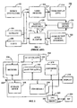
- FIG. 2 illustrates a graphical representation of a schematic block diagram of a system for automatic audio and video output synchronization 200.
- the system 200 includes a plurality of video processing devices 202 operably coupled across a network connection 204.
- the network 204 may be any suitable network, such as an Intranet, Internet, wireless network, wired network, or any other suitable compilation of connections allowing for interactive communication therethrough.
- the system 200 includes a receiver 206, a storage device 208, a first deinterlacer 210, a second deinterlacer 212, a first converter 214 and a second converter 216.
- the receiver 206 may be any suitable receiving device, such as a cable receiver, Internet video broadcast receiver, telco receiver, satellite receiver, and also includes a video source generator, such as a DVD player, a personal video recording device, a memory module storing audio and video therein, or any other suitable type of receivers or storage devices as recognized by one having ordinary skill in the art.
- a video source generator such as a DVD player, a personal video recording device, a memory module storing audio and video therein, or any other suitable type of receivers or storage devices as recognized by one having ordinary skill in the art.
- the first deinterlacer 210 and the second deinterlacer 212 may be any suitable type of processing device capable of performing deinterlacing operations.
- the first deinterlacer 210 may be disposed on a computing device operably coupled via a home network and the second deinterlacer 212 may be disposed within a processing device across an Internet connection.
- the first deinterlacer 210 and the second deinterlacer 212 may be disposed at any location such that they are in communication with the network 204 for receiving and communicating data thereacross.
- the first and second converters 214 and 216 may be any suitable type of converter capable of receiving an incoming data signal and thereupon converting a converted output signal.
- conversion techniques may be required to convert an incoming signal having an existing frame ratio to a corresponding frame ratio required for a specified display, such as display 218.
- converter one 214 and converter two 216 may also be located at any suitable location such that they are in operative communication with the network 204.
- the system 200 further includes a processing unit 220 which may be one or more processing devices capable of performing processing operations.
- the CPU 220 may further include a memory 222 capable of storing executable instructions such that the CPU 220 may be able to perform specific operations in response to the corresponding executable operations.
- the system 200 may further include an Internet service provider (ISP) 224 in operative communication with the CPU 220, such as across a network connection 226.
- ISP Internet service provider
- the ISP 224 may be any suitable outside connection, such as a third party software or other available resource, for providing the CPU 220 with extraneous processing operations or executable instructions.
- the present invention provides for generating a signal processing routine.
- the signal processing routine is generated by the master device which, as described above, is any processing device capable of controlling and generating a corresponding processing routine.
- the CPU 220 may be the master device based on the included processors.
- any other suitable device operably connected to the network 204 may be a suitable master device, referred to above as a master-capable device.
- the system 200 illustrates a single CPU 220 but in a networked computing environment, any suitable number of CPUs or other processing devices may be connected to the network 204.
- the master device determines the signal processing routine based on available resources. For example, the master device may determine a signal processing routine based on availability and quality of various components. For example, a system may have two deinterlacers, such as deinterlacer one 210 and deinterlacer two 212 which are capable of providing deinterlacing. The master device, the CPU 220, may determine that the first deinterlacer 210 is currently being utilized by different processing elements and is therefore unavailable or in another exemplary embodiment, the second deinterlacer 212 may have a lower quality rating than the first deinterlacer 210. As recognized by one having ordinary skill in the art, any suitable criteria may be utilized to determine which elements are utilized when more than one capable element exists in the network environment.
- a receiver 206 may receive an incoming signal 230, such as an NTSC signal.
- the receiver 206 may allow for conversion from NTSC format to 480i format of the signal.
- the second deinterlacer 212 may thereupon be a deinterlacer allowing for the conversion of 480i signal to 480p signal.
- the second converter 216 may allow for the conversion from a 60 Hz to an 85 Hz signal and the first converter 214 may allow for the conversion from a 480p data signal to a 1080p data signal.
- the display may also include requiring 85 Hz signal and 1080P data signal.
- the storage device 208 may include a tuner for a signal having 1080i data and the first deinterlacer 210 may include deinterlacing from 1080i to 1080p at 60 Hz. Therefore, to generate the proper display signal, the master device, the CPU 220, may generate a processing routine consisting of the receiver 206 to the second deinterlacer 212 to the second converter 216 to the first converter 214 and subsequently to the display 218. In this embodiment, the storage device 208 and the first deinterlacer 210 would not be accessed.
- the master device 220 would determine the delay in processing a video signal to generate a video display on the display 218. This delay would be calculated as a video delay time period and is based on the signal processing routine to generate the video display signal.
- the ISP 226 may provide for an off-site configuration service.
- an ISP 226 may include a system that recognizes available configurations and determines the signal processing routine using available ISP 226 algorithms and processing resources.
- FIG. 3 illustrates a further embodiment to the present invention.
- the CPU 220 in response to executable instructions 222, when the CPU 220 act as the master device, thereupon determines the video delay time period.
- the system 202 receives the incoming signal 230 which is also provided to an audio receiver 250.
- the audio receiver 250 may be any suitable type of audio receiving device as recognized by one having ordinary skill in the art.
- the audio receiver 250 is coupled to an audio display device 252 which may be any suitable type of device displaying audio output, such as a speaker or plurality of speakers in a speaker system.
- the CPU 220 provides the video delay time period 254 to the audio receiver 250.
- the audio receiver 250 in response to the video delay time period 254 thereupon sets an audio delay approximate the video delay time period.
- the audio receiver 250 operates in accordance to the standard audio receiver techniques to set an internal delay consisting of buffering a particular amount of audio output for a particular time period. Thereupon, the audio receiver 250 generates the audio output 256 such that the audio display device 252 and the video display 218 both provide audio and video output in synchronization with each other.
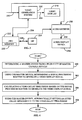
- FIG. 4 illustrates a flowchart with steps of one embodiment of a method for automatic audio and video output synchronization.
- the method begins by, if desired, determining a master device from a plurality of master-capable devices, step 300.
- the master device may be any suitable device capable of performing and processing operations as discussed above.
- the next step, step 302, if desired, is using the master device to determine a signal processing routine to generate a video display signal.
- the routine may include selecting one or more processing elements across a network or within a single processing environment to generate the video display signal.
- Step 304 is calculating a video delay time period based on the signal processing routine to generate the video display signal.
- step 306 is using the master device to automatically set an audio delay approximate to the video delay.
- the method is complete.
- the method may further include generating the video display signal using the signal processing routine such that the video display 218 provides a video output.
- the method further includes generating an audio display signal after a time interval of the video delay time period.
- the audio display signal may be generated and then buffered for a particular interval or may be buffered and then generated, regardless thereof the audio receiver, such as the audio receiver 250 of FIG. 3 , provides for a delayed output of the audio output signal 256.
- the present invention further includes determining a plurality of slave devices.
- a slave device is defined as any device capable of being a master device and all master-capable devices which are deemed to not be the particular master device. Therefore, in the exemplary embodiment discussed above with regards to FIG. 2 , the CPU 220 is determined to be the master, therefore the slave devices would be receiver 206, the storage device 208, the first deinterlacer 210, the second deinterlacer 212, the first converter 214 and the second converter 216. Thereupon, the signal processing routine is based on the plurality of slave devices.
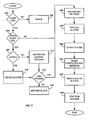
- FIG. 5 illustrates a flowchart of another embodiment of the present invention including the determination of the status of the processing elements within the audio and video synchronization process.
- the method begins by determining if a processing environment includes a communication channel, step 400. If no communication channel exists, an error is registered such that the present invention will be unable to determine a signal processing routine and therefore unable to provide for synchronized audio and video output.
- step 404 is to determine if other masters exist. If other masters exist, step 406 is deciding which of the available master-capable devices is to be the designated master.
- step 408 a decision is made as to which of the master-capable devices is the master.
- the decision of step 408 may be performed by determining which master-capable device has the most available processing resources, which devices are in communication with an external service provider, which devices are most aptly suited for performing this function such as using a ratings system, or any other suitable technique to decide which processing device is the master.
- step 406 if a particular processing device is not the processing device that determines which master-capable device is to be the master, the method proceeds to step 410 such that the master-capable devices listen for the master decision. Therefore, once a decision for one of the master-capable devices to become the master, a master decision signal may be sent to all of the master-capable devices indicating the decision of which processing device is to become the master. Thereupon, step 412 is a determination for each of the master-capable devices if that processing element is to be the master.
- step 412 If the determination of step 412 is that a master-capable device is not to be the master, that processing device thereupon automatically becomes a slave device 414. Although, if the determination of step 412 is yes, the processing device is to become the master device, the master device thereupon is to broadcast the master decision to all master-capable devices, step 416. Reverting back to step 410, therefore, if a processing device does not determine who is the master, the processing device performs step 410 to listen for the master decision and once a master decision is received, the processing device can determine if that device has in fact become the master or is to become a slave device. Also referring back to step 404, in the event there is only a single master-capable device, that device by default becomes the master such that the method would proceed to step 416.
- the method includes step 418 which is finding all slaves.
- the slaves include the elements disposed within the processing system 202 when the CPU 220 has been designated as the master.
- Step 420 is the query of the slaves to determine the processing capabilities and abilities of each of the slave devices.
- Step 422 is to make a configuration decision. This configuration decision may be based upon any suitable factors, as discussed above, or in another embodiment may be based on a third party providing configuration across an internet service provider, such as ISP 224 of FIG. 2 .
- a separate configuration service may be available such that a master device may provide the slave information to a configuration processing device which then upon generates the optimum configuration and provides the configuration decision back to the master device.
- the configuration decision is made and the configuration format is sent to the slaves, step 424.
- the configuration information includes information indicating where a particular slave should receive incoming video signal and to which device the slave may thereupon provide further signals.
- the master routes video information through a specific path using the slave devices.
- the receiver 206 of FIG. 2 may be instructed to provide information directly to the first deinterlacer 210 and the first deinterlacer 210 may thereupon provide information directly to the second converter 216.
- any suitable configuration may be utilized - with any suitable number of slave devices, specifically video processing devices or other suitable processing element to provide for configuration and subsequent display of video output.
- the slave devices wait for change data, step 426. Based upon subsequent change data, unless instructed otherwise, the slave devices will maintain an existing directional relationship of data flow from slave to slave or otherwise referred to as from processing element to processing element. Thereupon, in one embodiment of the present invention, the method is complete.
- the present invention improves over the prior art techniques, as discussed above with respect to FIG. 1 by not only configuring processing elements for video rendering, but also for the automatic determination of a delay time and the subsequent offset of audio processing.
- the present invention allows a user to seamlessly engage multiple processing elements in a networked environment for the generation of video rendering.
- the present invention further determines delays generated by these networked rendering environment and automatically offsets the corresponding audio output such that an end user simultaneously receives both the video and audio on separate output systems,
- the present invention could also subsequently delay the video output by a corresponding delay factor based on buffering video content for the determined time interval wherein the present invention buffers a delayed amount of audio information based on ease memory and buffering requirements for audio data compare with video data. Therefore, contemplated to cover by the present invention, any and all modifications, variations or equivalence that fall within the scope of the basic underlying principals disclosed and claimed herein.
Abstract
Description
- The present invention relates generally to synchronizing audio and video and more specifically to automatically synchronizing audio and video output in a multi-component multi-media processing system.
- In existing audio and video multi-media systems, there has been an increase in growth in separate audio and video processing components. In these typical systems, a first group of processing elements may be utilized to generate a video signal and a second group of processing elements may be utilized to generate an audio signal. For example, in a flat panel television display, the flat panel display does not necessarily include speakers. Therefore, a separate audio subsystem must be utilized, such as a surround sound system integrated within an existing viewing area, such as a living room.
-
FIG. 1 illustrates a graphical representation of a prior art audio andvideo processing system 100. The system includes asource device 102, such as any suitable source for generating an incoming signal. In one exemplary embodiment, the source may be a digital versatile disk (DVD) player, a digital video recording device, or any other suitable device capable of reading audio and video information off of a stored medium. In thesystem 100, other input sources such as asatellite receiver 104 or acable receiver 106 may also be utilized to receive incoming audio and video signals. - In the
system 100, avideo receiver 108 is operative to receive avideo signal 110 from at least one of the various sources, such as the exemplary sources of thevideo source 102,satellite receiver 104 orcable receiver 106. Thevideo receiver 108 may perform image processing operations to generate anoutput video signal 112 which is provided to avideo display 114, such as a standard television. - The
system 100 further includes anaudio receiver 116 which is operative to receive an audio signal 118 from at least one of the different sources, such as thevideo source 102,satellite receiver 104 andcable receiver 106. Theaudio receiver 116 may be any suitable audio receiving device capable of receiving the incoming audio signal and performing signal processing to generate anoutput audio signal 120 to an audio output device ordevices 122, such as speakers, 122. - In the
system 100, the prior art approach for synchronizing thevideo signal 112 and theaudio signal 120 to thevideo display 114 and correspondingaudio output devices 122, respectively, is manual configuration. Typically, during the installation of the signal processing components such as thevideo receiver 108 and theaudio receiver 116, a technician manually utilizes atesting device 124. The testing device may be any suitable processing device capable of receiving thevideo signal 112 and theaudio signal 120. Thetesting device 124 is operative to determine a delay interval between a particular frame ofvideo data 112 with acorresponding audio portion 120. Based on this calculated delay, the testing device then generates a delay signal 126 which is provided to a display for allowingmanual adjustment 128. -
FIG. 1 illustratesfunctional block 128 for manual adjustment, but as recognized by one having ordinary skill in the art,functional block 128 represents a physical action to be performed by a technician for manually adjusting acorresponding offset amount 130 within theaudio receiver 116. Therefore, due to utilization of a technician andmanual adjustment 128 of anoffset amount 130 based on the detected offset 126 from thetesting device 124, theaudio receiver 116 may be tweaked to align the audio output to the video output. - The current approach for synchronizing audio and video output requires
manual adjustment 128 of theaudio receiver 116 corresponding to delay within thevideo receiver 108. Not only does this approach require a technician or technically advanced user to manually adjust theaudio receiver 116, the present approach is only operative for the configuration of thevideo receiver 108. - With the growth of networking capabilities and multiple processing engines operably in communication across multiple networks, there exists the ability to allow for improved video rendering by using available rendering resources. If the combination of rendering resources is adjusted beyond the configuration within the
video receiver 108, the current approach would require furthermanual adjustment 128 to synchronize audio and video output. Furthermore, the manual adjustment would only be good for the existing solution and would once again require further adjustment of the timing sequence of audio and video output should any other configurations become available. - For example, if on a home computer network, a television set top box is in communication with a first home computer and a second home computer, different processing resources may be utilized between different computers and the set top box to allow for maximizing available processing resources and generating the best possible video output. Although, in this system there would require inherent delay based on video signal processing which must be correspondingly provided to the audio receiver, such as the
audio receiver 116. Current techniques do not allow for automatic adjustment of timing sequences for synchronizing audio and video output. Therefore, there exists a need for improving synchronization of audio and video output signals in a networking environment. - European
patent applications EP 1 067 773 A andEP 1 104 179 A - According to the present invention there is provided a method for automatic audio and video output synchronization and a system for automatic audio and video output synchronization as claimed in
claims 1 and 11. -
-
FIG. 1 illustrates a block diagram of a prior art audio and video synchronization system; -
FIG.2 illustrates a schematic block diagram of a system for audio and video synchronization in accordance with one embodiment of the present invention; -
FIG. 3 illustrates a schematic block diagram of one embodiment of a system for audio and video synchronization; -
FIG. 4 illustrates a flowchart of a method for audio and video synchronization in accordance with one embodiment of the present invention; and -
FIG. 5 illustrates a flowchart of a method for generating a master and processing device configuration routine in accordance with one embodiment of the present invention. - Briefly, the present invention provides for automatic audio and video synchronization by calculating a video delay time period based on a signal processing routine to generate the video display signal and automatically setting an audio delay to approximate the video delay time period. In addition the method may include if desired, determining a master device from a plurality of master capable devices. The master device is a processing device including one or more processors capable of making configuration decisions and designating a data flow for rendering a video signal. The master-capable devices are any suitable processing devices which are capable of acting as a master device. The present invention may further include using the master device to determine a signal processing routine to generate a video display signal. The signal processing routine includes a designated data flow from one processing element to a next processing element to a next processing element and so on for different stages of video signal rendering.
- The video delay time period may be calculated based on the delay of an incoming video signal and the signal being provided to all of the different processing devices until the generation of a subsequent video output signal. Furthermore, the present invention includes using the master device to automatically set an audio delay in an audio processing device to a time period approximate to the video delay time period. The audio processing device may be any suitable audio processor capable of receiving an incoming audio signal and thereupon generating a corresponding audio output signal for an audio display, such as a plurality of speakers.
- Thereupon, the present invention allows for the automatic adjustment of audio and video synchronization. A master device is determined from a plurality of master capable devices such that the master device determines the system processing routine. In a network system, multiple signal processing routines may be utilized based on available resources. Using various techniques, optimized signal processing routines may be determined which have varying delays. The present invention allows for not only the generation of a particular processing routine, but also the determination of the corresponding delay and the automatic audio offset relative to the delay, thereby seamlessly providing an end user with synchronized audio and video output across two different output devices.
-
FIG. 2 illustrates a graphical representation of a schematic block diagram of a system for automatic audio and video output synchronization 200. The system 200 includes a plurality ofvideo processing devices 202 operably coupled across anetwork connection 204. Thenetwork 204 may be any suitable network, such as an Intranet, Internet, wireless network, wired network, or any other suitable compilation of connections allowing for interactive communication therethrough. In one exemplary embodiment illustrated inFIG. 2 , the system 200 includes areceiver 206, astorage device 208, afirst deinterlacer 210, asecond deinterlacer 212, afirst converter 214 and asecond converter 216. Thereceiver 206 may be any suitable receiving device, such as a cable receiver, Internet video broadcast receiver, telco receiver, satellite receiver, and also includes a video source generator, such as a DVD player, a personal video recording device, a memory module storing audio and video therein, or any other suitable type of receivers or storage devices as recognized by one having ordinary skill in the art. - The
first deinterlacer 210 and thesecond deinterlacer 212 may be any suitable type of processing device capable of performing deinterlacing operations. For example, thefirst deinterlacer 210 may be disposed on a computing device operably coupled via a home network and thesecond deinterlacer 212 may be disposed within a processing device across an Internet connection. As recognized by one having ordinary skill in the art, thefirst deinterlacer 210 and thesecond deinterlacer 212 may be disposed at any location such that they are in communication with thenetwork 204 for receiving and communicating data thereacross. - The first and
second converters display 218, conversion techniques may be required to convert an incoming signal having an existing frame ratio to a corresponding frame ratio required for a specified display, such asdisplay 218. It should also be noted that converter one 214 and converter two 216 may also be located at any suitable location such that they are in operative communication with thenetwork 204. - The system 200 further includes a
processing unit 220 which may be one or more processing devices capable of performing processing operations. In one embodiment, theCPU 220 may further include amemory 222 capable of storing executable instructions such that theCPU 220 may be able to perform specific operations in response to the corresponding executable operations. - In one embodiment, the system 200 may further include an Internet service provider (ISP) 224 in operative communication with the
CPU 220, such as across anetwork connection 226. TheISP 224 may be any suitable outside connection, such as a third party software or other available resource, for providing theCPU 220 with extraneous processing operations or executable instructions. - The present invention provides for generating a signal processing routine. In one embodiment, the signal processing routine is generated by the master device which, as described above, is any processing device capable of controlling and generating a corresponding processing routine. In one exemplary embodiment, the
CPU 220 may be the master device based on the included processors. Although, it should be noted that any other suitable device operably connected to thenetwork 204 may be a suitable master device, referred to above as a master-capable device. As also noted, the system 200 illustrates asingle CPU 220 but in a networked computing environment, any suitable number of CPUs or other processing devices may be connected to thenetwork 204. - In the exemplary embodiment of the
CPU 220 acting as a master device, the master device determines the signal processing routine based on available resources. For example, the master device may determine a signal processing routine based on availability and quality of various components. For example, a system may have two deinterlacers, such as deinterlacer one 210 and deinterlacer two 212 which are capable of providing deinterlacing. The master device, theCPU 220, may determine that thefirst deinterlacer 210 is currently being utilized by different processing elements and is therefore unavailable or in another exemplary embodiment, thesecond deinterlacer 212 may have a lower quality rating than thefirst deinterlacer 210. As recognized by one having ordinary skill in the art, any suitable criteria may be utilized to determine which elements are utilized when more than one capable element exists in the network environment. - In one example, a
receiver 206 may receive anincoming signal 230, such as an NTSC signal. Thereceiver 206 may allow for conversion from NTSC format to 480i format of the signal. Thesecond deinterlacer 212 may thereupon be a deinterlacer allowing for the conversion of 480i signal to 480p signal. Thesecond converter 216 may allow for the conversion from a 60 Hz to an 85 Hz signal and thefirst converter 214 may allow for the conversion from a 480p data signal to a 1080p data signal. In the exemplary embodiment, the display may also include requiring 85 Hz signal and 1080P data signal. In this exemplary embodiment, thestorage device 208 may include a tuner for a signal having 1080i data and thefirst deinterlacer 210 may include deinterlacing from 1080i to 1080p at 60 Hz. Therefore, to generate the proper display signal, the master device, theCPU 220, may generate a processing routine consisting of thereceiver 206 to thesecond deinterlacer 212 to thesecond converter 216 to thefirst converter 214 and subsequently to thedisplay 218. In this embodiment, thestorage device 208 and thefirst deinterlacer 210 would not be accessed. - Therefore, the
master device 220 would determine the delay in processing a video signal to generate a video display on thedisplay 218. This delay would be calculated as a video delay time period and is based on the signal processing routine to generate the video display signal. In one embodiment, theISP 226 may provide for an off-site configuration service. For example, anISP 226 may include a system that recognizes available configurations and determines the signal processing routine usingavailable ISP 226 algorithms and processing resources. -
FIG. 3 illustrates a further embodiment to the present invention. TheCPU 220, in response toexecutable instructions 222, when theCPU 220 act as the master device, thereupon determines the video delay time period. Thesystem 202 receives theincoming signal 230 which is also provided to anaudio receiver 250. Theaudio receiver 250 may be any suitable type of audio receiving device as recognized by one having ordinary skill in the art. Theaudio receiver 250 is coupled to anaudio display device 252 which may be any suitable type of device displaying audio output, such as a speaker or plurality of speakers in a speaker system. TheCPU 220 provides the videodelay time period 254 to theaudio receiver 250. Theaudio receiver 250 in response to the videodelay time period 254 thereupon sets an audio delay approximate the video delay time period. Theaudio receiver 250 operates in accordance to the standard audio receiver techniques to set an internal delay consisting of buffering a particular amount of audio output for a particular time period. Thereupon, theaudio receiver 250 generates theaudio output 256 such that theaudio display device 252 and thevideo display 218 both provide audio and video output in synchronization with each other. -
FIG. 4 illustrates a flowchart with steps of one embodiment of a method for automatic audio and video output synchronization. The method begins by, if desired, determining a master device from a plurality of master-capable devices,step 300. As discussed above, the master device may be any suitable device capable of performing and processing operations as discussed above. The next step, step 302, if desired, is using the master device to determine a signal processing routine to generate a video display signal. As discussed above, the routine may include selecting one or more processing elements across a network or within a single processing environment to generate the video display signal. Step 304 is calculating a video delay time period based on the signal processing routine to generate the video display signal. Thereupon,step 306 is using the master device to automatically set an audio delay approximate to the video delay. Thereupon, in one embodiment of present invention, the method is complete. - The method may further include generating the video display signal using the signal processing routine such that the
video display 218 provides a video output. The method further includes generating an audio display signal after a time interval of the video delay time period. The audio display signal may be generated and then buffered for a particular interval or may be buffered and then generated, regardless thereof the audio receiver, such as theaudio receiver 250 ofFIG. 3 , provides for a delayed output of theaudio output signal 256. - The present invention further includes determining a plurality of slave devices. As discussed with respect to
FIG. 2 , a slave device is defined as any device capable of being a master device and all master-capable devices which are deemed to not be the particular master device. Therefore, in the exemplary embodiment discussed above with regards toFIG. 2 , theCPU 220 is determined to be the master, therefore the slave devices would bereceiver 206, thestorage device 208, thefirst deinterlacer 210, thesecond deinterlacer 212, thefirst converter 214 and thesecond converter 216. Thereupon, the signal processing routine is based on the plurality of slave devices. -
FIG. 5 illustrates a flowchart of another embodiment of the present invention including the determination of the status of the processing elements within the audio and video synchronization process. The method begins by determining if a processing environment includes a communication channel,step 400. If no communication channel exists, an error is registered such that the present invention will be unable to determine a signal processing routine and therefore unable to provide for synchronized audio and video output. In the event that a communication channel does exist,step 404 is to determine if other masters exist. If other masters exist,step 406 is deciding which of the available master-capable devices is to be the designated master. - If a particular master-capable device is determined to be the device that determines which device is the master, the method proceeds to step 408 such that a decision is made as to which of the master-capable devices is the master. For example, the decision of
step 408 may be performed by determining which master-capable device has the most available processing resources, which devices are in communication with an external service provider, which devices are most aptly suited for performing this function such as using a ratings system, or any other suitable technique to decide which processing device is the master. - In
step 406, if a particular processing device is not the processing device that determines which master-capable device is to be the master, the method proceeds to step 410 such that the master-capable devices listen for the master decision. Therefore, once a decision for one of the master-capable devices to become the master, a master decision signal may be sent to all of the master-capable devices indicating the decision of which processing device is to become the master. Thereupon,step 412 is a determination for each of the master-capable devices if that processing element is to be the master. - If the determination of
step 412 is that a master-capable device is not to be the master, that processing device thereupon automatically becomes aslave device 414. Although, if the determination ofstep 412 is yes, the processing device is to become the master device, the master device thereupon is to broadcast the master decision to all master-capable devices,step 416. Reverting back to step 410, therefore, if a processing device does not determine who is the master, the processing device performsstep 410 to listen for the master decision and once a master decision is received, the processing device can determine if that device has in fact become the master or is to become a slave device. Also referring back to step 404, in the event there is only a single master-capable device, that device by default becomes the master such that the method would proceed to step 416. - After
step 416, the method includesstep 418 which is finding all slaves. As discussed above with respect toFIG. 2 , the slaves include the elements disposed within theprocessing system 202 when theCPU 220 has been designated as the master. Step 420 is the query of the slaves to determine the processing capabilities and abilities of each of the slave devices. Step 422 is to make a configuration decision. This configuration decision may be based upon any suitable factors, as discussed above, or in another embodiment may be based on a third party providing configuration across an internet service provider, such asISP 224 ofFIG. 2 . In one embodiment, a separate configuration service may be available such that a master device may provide the slave information to a configuration processing device which then upon generates the optimum configuration and provides the configuration decision back to the master device. - Regardless thereof, the configuration decision is made and the configuration format is sent to the slaves,
step 424. In one embodiment, the configuration information includes information indicating where a particular slave should receive incoming video signal and to which device the slave may thereupon provide further signals. As such, the master routes video information through a specific path using the slave devices. For example, thereceiver 206 ofFIG. 2 may be instructed to provide information directly to thefirst deinterlacer 210 and thefirst deinterlacer 210 may thereupon provide information directly to thesecond converter 216. As recognized by one having ordinary skill in the art, any suitable configuration may be utilized - with any suitable number of slave devices, specifically video processing devices or other suitable processing element to provide for configuration and subsequent display of video output. - Thereupon, from the system perspective, the slave devices wait for change data,
step 426. Based upon subsequent change data, unless instructed otherwise, the slave devices will maintain an existing directional relationship of data flow from slave to slave or otherwise referred to as from processing element to processing element. Thereupon, in one embodiment of the present invention, the method is complete. - As such, the present invention improves over the prior art techniques, as discussed above with respect to
FIG. 1 by not only configuring processing elements for video rendering, but also for the automatic determination of a delay time and the subsequent offset of audio processing. The present invention allows a user to seamlessly engage multiple processing elements in a networked environment for the generation of video rendering. The present invention further determines delays generated by these networked rendering environment and automatically offsets the corresponding audio output such that an end user simultaneously receives both the video and audio on separate output systems, - It should be understood that the implementation of other variations and modifications of the invention in its various aspects would be apparent to those ordinary skill in the art, if the invention is not limited by the specific embodiment described herein. For example, the present invention could also subsequently delay the video output by a corresponding delay factor based on buffering video content for the determined time interval wherein the present invention buffers a delayed amount of audio information based on ease memory and buffering requirements for audio data compare with video data. Therefore, contemplated to cover by the present invention, any and all modifications, variations or equivalence that fall within the scope of the basic underlying principals disclosed and claimed herein.
Claims (18)
- A method for automatic audio and video output synchronization, the method comprising:calculating a video delay time period based on a signal processing routine including a designated data flow between a plurality of processing elements to generate the video display signal; and:automatically setting an audio delay to approximate the video delay time period;
characterised by:determining a plurality of slave devices as the plurality of processing elements to generate the video display signal; anddetermining the signal processing routine comprising the designated data flow between the plurality of slave devices based on the availability and quality of each of the plurality of slave devices by a master device. - The method of claim 1, further comprising generating the video display signal using the signal processing routine.
- The method of claim 1 or claim 2, further comprising generating an audio display signal after a time interval of the video delay time period.
- The method of claim 3, further comprising providing the audio display signal to an audio display device, wherein the audio display device is a plurality of speakers.
- The method of any one of the preceding claims, further comprising:providing the video display signal to a video display device.
- The method of claim 5, wherein the video display device is a digital television.
- The method of any one of claims 1 to 6, further comprising routing video information via a specified path corresponding to the signal processing routine using the plurality of slave devices.
- The method of any one of claims 1 to 7, wherein at least one of the slave devices is also a master-capable device.
- The method of any one of claims 1 to 8, wherein the master device and the plurality of slave devices are in operative communication across a network.
- The method of any one of claims 1 to 9, including:determining a master device from a plurality of master-capable devices; andusing the master device, determining the signal processing routine to generate the video display signal.
- A system (200) for automatic audio and video output synchronization, the system, characterised by:a plurality of operably coupled slave devices (206,208,210,212,214,216);a master device (220) operable coupled to the plurality of slave devices (206,208,210,212,214,216), the master device (220) operative to determine a signal processing routine including a designated data flow between the plurality of slave devices (206,208,210,212,214,216) based on the availability and quality of each of the plurality of slave devices (206,208,210,212,214,216) and the master device (220) operative to calculate a video delay time period based on the signal processing routine;one of the plurality of slave devices (206,208,210,212,214,216) operative to receive a video input signal and at least one of the plurality of slave devices (206,208,210,212,214,216) operative to generate a video output signal; andan audio receiver (250) operably coupled to receive an audio input signal and operative to generate an audio output signal delayed by a time period approximate to the video delay period.
- The system of claim 11, wherein the master device (220) is operably coupled to the plurality of slave devices across (206,208,210,212,214,216) a network (204).
- The system of any one of claims 11 to 12, wherein each of the plurality of slave devices (206,208,210,212,214,216) is a video processing device (202).
- The system of any one of claims 11 to 13, wherein the master device (220) is operably coupled to an audio processing device such that the audio delay may be programmed in the audio processing device.
- The system of any one of claims 11 to 14, further comprising at least one master-capable device, each of which is capable of acting as the master device (220), wherein the master device (220) is one of the at least one master-capable device and is operative to determine or is capable of being instructed that it is the master device (220).
- The system of claim 15, wherein one or more of the plurality of slave devices (206,208,210,212,214,216) is a corresponding one of the at least one master-capable device.
- The system of any one of claims 11 to 16, wherein the master device (220) comprises:memory (222) operative to store a plurality of executable instructions; andat least one processing device operably coupled to the memory (222) such that the at least one processing device is operative in response to the executable instructions to:determine the signal processing routine based on at least one of the plurality of slave devices (206,208,210,212,214,216); andcalculate the video delay time period based on the signal processing routine.
- The system of any one of claims 11 to 17, wherein the master device (220) is operable to route the video information through a specific path corresponding to the determined signal processing routine using the plurality of slave devices (206,208,210,212,214,216).
Applications Claiming Priority (2)
| Application Number | Priority Date | Filing Date | Title |
|---|---|---|---|
| US10/907,073 US20060209210A1 (en) | 2005-03-18 | 2005-03-18 | Automatic audio and video synchronization |
| PCT/IB2006/000774 WO2006097845A1 (en) | 2005-03-18 | 2006-03-17 | Automatic audio and video synchronization |
Publications (2)
| Publication Number | Publication Date |
|---|---|
| EP1864483A1 EP1864483A1 (en) | 2007-12-12 |
| EP1864483B1 true EP1864483B1 (en) | 2011-05-18 |
Family
ID=36441322
Family Applications (1)
| Application Number | Title | Priority Date | Filing Date |
|---|---|---|---|
| EP06727417A Expired - Fee Related EP1864483B1 (en) | 2005-03-18 | 2006-03-17 | Automatic audio and video synchronization |
Country Status (4)
| Country | Link |
|---|---|
| US (1) | US20060209210A1 (en) |
| EP (1) | EP1864483B1 (en) |
| CN (1) | CN101204081B (en) |
| WO (1) | WO2006097845A1 (en) |
Families Citing this family (19)
| Publication number | Priority date | Publication date | Assignee | Title |
|---|---|---|---|---|
| US8133115B2 (en) | 2003-10-22 | 2012-03-13 | Sony Computer Entertainment America Llc | System and method for recording and displaying a graphical path in a video game |
| US20060071933A1 (en) | 2004-10-06 | 2006-04-06 | Sony Computer Entertainment Inc. | Application binary interface for multi-pass shaders |
| WO2006118106A1 (en) * | 2005-04-28 | 2006-11-09 | Matsushita Electric Industrial Co., Ltd. | Lip-sync correcting device and lip-sync correcting method |
| US7636126B2 (en) | 2005-06-22 | 2009-12-22 | Sony Computer Entertainment Inc. | Delay matching in audio/video systems |
| US7965338B2 (en) * | 2006-04-06 | 2011-06-21 | Microsoft Corporation | Media player audio video synchronization |
| US7965859B2 (en) | 2006-05-04 | 2011-06-21 | Sony Computer Entertainment Inc. | Lighting control of a user environment via a display device |
| US7880746B2 (en) | 2006-05-04 | 2011-02-01 | Sony Computer Entertainment Inc. | Bandwidth management through lighting control of a user environment via a display device |
| CN101330402B (en) * | 2007-08-01 | 2012-04-18 | 中兴通讯股份有限公司 | Method for collocating business for customer equipment of individual network management business |
| US8743284B2 (en) * | 2007-10-08 | 2014-06-03 | Motorola Mobility Llc | Synchronizing remote audio with fixed video |
| US8327029B1 (en) * | 2010-03-12 | 2012-12-04 | The Mathworks, Inc. | Unified software construct representing multiple synchronized hardware systems |
| CN113490134B (en) * | 2010-03-23 | 2023-06-09 | 杜比实验室特许公司 | Audio reproducing method and sound reproducing system |
| US10158958B2 (en) * | 2010-03-23 | 2018-12-18 | Dolby Laboratories Licensing Corporation | Techniques for localized perceptual audio |
| US10786736B2 (en) | 2010-05-11 | 2020-09-29 | Sony Interactive Entertainment LLC | Placement of user information in a game space |
| US8606953B2 (en) | 2010-10-04 | 2013-12-10 | Dialogic Corporation | Adjusting audio and video synchronization of 3G TDM streams |
| US9342817B2 (en) | 2011-07-07 | 2016-05-17 | Sony Interactive Entertainment LLC | Auto-creating groups for sharing photos |
| US20170142295A1 (en) * | 2014-06-30 | 2017-05-18 | Nec Display Solutions, Ltd. | Display device and display method |
| CN106375788A (en) * | 2016-09-05 | 2017-02-01 | Tcl集团股份有限公司 | Program synchronizing method and system |
| JP2019004401A (en) * | 2017-06-19 | 2019-01-10 | セイコーエプソン株式会社 | Projection system, projector, and control method for projection system |
| CN112860211B (en) * | 2021-01-28 | 2022-12-27 | 成都极米科技股份有限公司 | Method, device, terminal and storage medium for determining time delay |
Family Cites Families (50)
| Publication number | Priority date | Publication date | Assignee | Title |
|---|---|---|---|---|
| US4313135B1 (en) * | 1980-07-28 | 1996-01-02 | J Carl Cooper | Method and apparatus for preserving or restoring audio to video |
| US5202761A (en) * | 1984-11-26 | 1993-04-13 | Cooper J Carl | Audio synchronization apparatus |
| JPH06282612A (en) * | 1993-03-29 | 1994-10-07 | Matsushita Electric Ind Co Ltd | Picture and audio processor and picture and audio processing method |
| US5486864A (en) * | 1993-05-13 | 1996-01-23 | Rca Thomson Licensing Corporation | Differential time code method and apparatus as for a compressed video signal |
| US5381181A (en) * | 1993-05-13 | 1995-01-10 | Thomson Consumer Electronics, Inc. | Clock recovery apparatus as for a compressed video signal |
| US5430485A (en) * | 1993-09-30 | 1995-07-04 | Thomson Consumer Electronics, Inc. | Audio/video synchronization in a digital transmission system |
| US5467139A (en) * | 1993-09-30 | 1995-11-14 | Thomson Consumer Electronics, Inc. | Muting apparatus for a compressed audio/video signal receiver |
| US5731799A (en) * | 1994-06-17 | 1998-03-24 | Motorola Inc. | Pixel-wise video registration system |
| US5530483A (en) * | 1994-10-11 | 1996-06-25 | Pixel Instruments Corp. | Delay detector apparatus and method for plural image sequences |
| EP0717236B1 (en) * | 1994-12-16 | 2001-08-16 | Canon Kabushiki Kaisha | Illumination device and liquid crystal display apparatus including same |
| US6836295B1 (en) * | 1995-12-07 | 2004-12-28 | J. Carl Cooper | Audio to video timing measurement for MPEG type television systems |
| JPH09205618A (en) * | 1996-01-29 | 1997-08-05 | Mitsubishi Electric Corp | Dynamic image sound expansion reproduction device and dynamic image sound synchronization controller |
| JP3130464B2 (en) * | 1996-02-02 | 2001-01-31 | ローム株式会社 | Data decryption device |
| JP3698376B2 (en) * | 1996-08-19 | 2005-09-21 | 松下電器産業株式会社 | Synchronous playback device |
| JP3106987B2 (en) * | 1997-01-09 | 2000-11-06 | 日本電気株式会社 | Audio / video synchronous playback device |
| JP3063838B2 (en) * | 1997-10-02 | 2000-07-12 | 日本電気株式会社 | Audio / video synchronous playback apparatus and method |
| IL123906A0 (en) * | 1998-03-31 | 1998-10-30 | Optibase Ltd | Method for synchronizing audio and video streams |
| US6016166A (en) * | 1998-08-31 | 2000-01-18 | Lucent Technologies Inc. | Method and apparatus for adaptive synchronization of digital video and audio playback in a multimedia playback system |
| US6199136B1 (en) * | 1998-09-02 | 2001-03-06 | U.S. Philips Corporation | Method and apparatus for a low data-rate network to be represented on and controllable by high data-rate home audio/video interoperability (HAVi) network |
| US6285405B1 (en) * | 1998-10-14 | 2001-09-04 | Vtel Corporation | System and method for synchronizing data signals |
| JP3094999B2 (en) * | 1998-10-15 | 2000-10-03 | 日本電気株式会社 | Audio / video synchronous playback device |
| US6615243B1 (en) * | 1999-04-01 | 2003-09-02 | Thomson Licensing S.A. | System and method for programming and transmitting macros for controlling audio/video devices |
| AU4858600A (en) * | 1999-05-19 | 2000-12-05 | Advanced Testing Technologies, Inc. | Unified analog/digital waveform software analysis tool with video and audio signal analysis methods |
| DE19930824C2 (en) * | 1999-07-03 | 2001-05-31 | Grundig Ag | Image and sound reproduction device and method for its operation |
| US6526581B1 (en) * | 1999-08-03 | 2003-02-25 | Ucentric Holdings, Llc | Multi-service in-home network with an open interface |
| GB9921049D0 (en) * | 1999-09-07 | 1999-11-10 | Koninkl Philips Electronics Nv | Clustered networked devices |
| DE19956913C2 (en) * | 1999-11-26 | 2001-11-29 | Grundig Ag | Method and device for adjusting the time difference between video and audio signals in a television set |
| US7203557B1 (en) * | 2000-01-05 | 2007-04-10 | Silicon Image, Inc. | Audio signal delay apparatus and method |
| GB0000874D0 (en) * | 2000-01-14 | 2000-03-08 | Koninkl Philips Electronics Nv | Latency handling for interconnected devices |
| US6654956B1 (en) * | 2000-04-10 | 2003-11-25 | Sigma Designs, Inc. | Method, apparatus and computer program product for synchronizing presentation of digital video data with serving of digital video data |
| WO2002013540A2 (en) * | 2000-08-10 | 2002-02-14 | Thomson Licensing S.A. | System and method for enabling audio speed conversion |
| SE517245C2 (en) * | 2000-09-14 | 2002-05-14 | Ericsson Telefon Ab L M | Synchronization of audio and video signals |
| US6870570B1 (en) * | 2000-10-31 | 2005-03-22 | Matsushita Electric Industrial Co., Ltd. | Television receiver with shared data port and control software |
| US6630963B1 (en) * | 2001-01-23 | 2003-10-07 | Digeo, Inc. | Synchronizing a video program from a television broadcast with a secondary audio program |
| US7030930B2 (en) * | 2001-03-06 | 2006-04-18 | Ati Technologies, Inc. | System for digitized audio stream synchronization and method thereof |
| JP2002290932A (en) * | 2001-03-27 | 2002-10-04 | Toshiba Corp | Digital broadcasting receiver and method for controlling it |
| US20030046693A1 (en) * | 2001-08-29 | 2003-03-06 | Digeo, Inc. | System and method for focused navigation within an interactive television user interface |
| US6906755B2 (en) * | 2002-01-04 | 2005-06-14 | Microsoft Corporation | Method and apparatus for synchronizing audio and video data |
| US7310808B2 (en) * | 2002-03-29 | 2007-12-18 | Sony Corporation | Method of and apparatus for supporting and enabling the selection and mixing of multiple streams of audio/video data from multiple sources within a receiving device allowing external control |
| US6792323B2 (en) * | 2002-06-27 | 2004-09-14 | Openpeak Inc. | Method, system, and computer program product for managing controlled residential or non-residential environments |
| US7024256B2 (en) * | 2002-06-27 | 2006-04-04 | Openpeak Inc. | Method, system, and computer program product for automatically managing components within a controlled environment |
| AU2003249527A1 (en) * | 2002-08-06 | 2004-02-25 | Koninklijke Philips Electronics N.V. | A network establishment and management protocol |
| US7234115B1 (en) * | 2002-09-26 | 2007-06-19 | Home Director, Inc. | Home entertainment system and method |
| US7280813B2 (en) * | 2003-03-13 | 2007-10-09 | Peter Fortier Elliott | Variable delay radio receiver |
| JP2005268866A (en) * | 2004-03-16 | 2005-09-29 | Orion Denki Kk | Video/audio output apparatus capable of automatically adjusting output |
| KR100651894B1 (en) * | 2004-07-23 | 2006-12-06 | 엘지전자 주식회사 | Display device and control method of the same |
| US7636126B2 (en) * | 2005-06-22 | 2009-12-22 | Sony Computer Entertainment Inc. | Delay matching in audio/video systems |
| US20070250311A1 (en) * | 2006-04-25 | 2007-10-25 | Glen Shires | Method and apparatus for automatic adjustment of play speed of audio data |
| US7953118B2 (en) * | 2006-12-08 | 2011-05-31 | Microsoft Corporation | Synchronizing media streams across multiple devices |
| US8272008B2 (en) * | 2007-02-28 | 2012-09-18 | At&T Intellectual Property I, L.P. | Methods, systems, and products for retrieving audio signals |
-
2005
- 2005-03-18 US US10/907,073 patent/US20060209210A1/en not_active Abandoned
-
2006
- 2006-03-17 WO PCT/IB2006/000774 patent/WO2006097845A1/en not_active Application Discontinuation
- 2006-03-17 CN CN2006800088213A patent/CN101204081B/en not_active Expired - Fee Related
- 2006-03-17 EP EP06727417A patent/EP1864483B1/en not_active Expired - Fee Related
Also Published As
| Publication number | Publication date |
|---|---|
| US20060209210A1 (en) | 2006-09-21 |
| EP1864483A1 (en) | 2007-12-12 |
| CN101204081A (en) | 2008-06-18 |
| WO2006097845A1 (en) | 2006-09-21 |
| CN101204081B (en) | 2012-07-04 |
Similar Documents
| Publication | Publication Date | Title |
|---|---|---|
| EP1864483B1 (en) | Automatic audio and video synchronization | |
| US8786779B2 (en) | Signal processing apparatus and method thereof | |
| US9871992B2 (en) | Content output apparatus, mobile apparatus, and controlling methods thereof | |
| CN1981524B (en) | Information processing device and method | |
| CN1292588C (en) | Video-voice synchronizer | |
| JP2001346121A (en) | Display device with two-screen function | |
| US20050021827A1 (en) | Data processing device, data processing system, data processing method, data processing program and recording medium storing the program | |
| US8612857B2 (en) | Monitor configuration for media device | |
| US20130128953A1 (en) | Reproduction apparatus, reproduction method, and program | |
| JP2012533910A (en) | Synchronization control system including main device and slave device and synchronization control method thereof | |
| KR20080110083A (en) | Tiled-display system and synchronization method in the system | |
| CN111147906B (en) | Synchronous playing system and synchronous playing method | |
| US7254644B2 (en) | Communication method and system for transmission and reception of packets collecting sporadically input data | |
| JP6956354B2 (en) | Video signal output device, control method, and program | |
| CN101616291A (en) | Image processing equipment and method and program thereof | |
| JP2009017240A (en) | Broadcast receiver and output characteristic adjustment method in the broadcast receiver | |
| US20050273657A1 (en) | Information processing apparatus and method, and recording medium and program for controlling the same | |
| US10917465B2 (en) | Synchronization setting device and distribution system | |
| JP3201298B2 (en) | Network data synchronization method and apparatus, synchronization node, and network system | |
| JP2010011181A (en) | Pulldown signal detector, pulldown signal detection method, and progressive scanning converter | |
| EP2579566A1 (en) | Electronic device and method for providing a combined data set relating to program information | |
| JP2020010298A (en) | Output device, synchronous control system, theses control method, and program | |
| JP5735360B2 (en) | Information terminal, information device, and system comprising these | |
| JP4016366B2 (en) | Interface device and video signal processing method | |
| JP2010016449A (en) | Group communication apparatus and group communication program |
Legal Events
| Date | Code | Title | Description |
|---|---|---|---|
| PUAI | Public reference made under article 153(3) epc to a published international application that has entered the european phase |
Free format text: ORIGINAL CODE: 0009012 |
|
| 17P | Request for examination filed |
Effective date: 20071011 |
|
| AK | Designated contracting states |
Kind code of ref document: A1 Designated state(s): DE FR GB |
|
| 17Q | First examination report despatched |
Effective date: 20080208 |
|
| DAX | Request for extension of the european patent (deleted) | ||
| RBV | Designated contracting states (corrected) |
Designated state(s): DE FR GB |
|
| RAP1 | Party data changed (applicant data changed or rights of an application transferred) |
Owner name: ATI TECHNOLOGIES ULC |
|
| RAP1 | Party data changed (applicant data changed or rights of an application transferred) |
Owner name: BROADCOM CORPORATION |
|
| GRAP | Despatch of communication of intention to grant a patent |
Free format text: ORIGINAL CODE: EPIDOSNIGR1 |
|
| RIN1 | Information on inventor provided before grant (corrected) |
Inventor name: SWAN, PHILIP Inventor name: STRASSER, DAVID, A. |
|
| GRAS | Grant fee paid |
Free format text: ORIGINAL CODE: EPIDOSNIGR3 |
|
| GRAA | (expected) grant |
Free format text: ORIGINAL CODE: 0009210 |
|
| AK | Designated contracting states |
Kind code of ref document: B1 Designated state(s): DE FR GB |
|
| REG | Reference to a national code |
Ref country code: GB Ref legal event code: FG4D |
|
| REG | Reference to a national code |
Ref country code: DE Ref legal event code: R096 Ref document number: 602006022037 Country of ref document: DE Effective date: 20110630 |
|
| PLBE | No opposition filed within time limit |
Free format text: ORIGINAL CODE: 0009261 |
|
| STAA | Information on the status of an ep patent application or granted ep patent |
Free format text: STATUS: NO OPPOSITION FILED WITHIN TIME LIMIT |
|
| 26N | No opposition filed |
Effective date: 20120221 |
|
| REG | Reference to a national code |
Ref country code: DE Ref legal event code: R097 Ref document number: 602006022037 Country of ref document: DE Effective date: 20120221 |
|
| REG | Reference to a national code |
Ref country code: FR Ref legal event code: ST Effective date: 20121130 |
|
| PG25 | Lapsed in a contracting state [announced via postgrant information from national office to epo] |
Ref country code: FR Free format text: LAPSE BECAUSE OF NON-PAYMENT OF DUE FEES Effective date: 20120402 |
|
| PGFP | Annual fee paid to national office [announced via postgrant information from national office to epo] |
Ref country code: DE Payment date: 20130331 Year of fee payment: 8 Ref country code: GB Payment date: 20130318 Year of fee payment: 8 |
|
| REG | Reference to a national code |
Ref country code: DE Ref legal event code: R119 Ref document number: 602006022037 Country of ref document: DE |
|
| GBPC | Gb: european patent ceased through non-payment of renewal fee |
Effective date: 20140317 |
|
| REG | Reference to a national code |
Ref country code: DE Ref legal event code: R119 Ref document number: 602006022037 Country of ref document: DE Effective date: 20141001 |
|
| PG25 | Lapsed in a contracting state [announced via postgrant information from national office to epo] |
Ref country code: GB Free format text: LAPSE BECAUSE OF NON-PAYMENT OF DUE FEES Effective date: 20140317 Ref country code: DE Free format text: LAPSE BECAUSE OF NON-PAYMENT OF DUE FEES Effective date: 20141001 |