EP1864591A1 - Device for mounting cables in office furnitures - Google Patents
Device for mounting cables in office furnitures Download PDFInfo
- Publication number
- EP1864591A1 EP1864591A1 EP07079502A EP07079502A EP1864591A1 EP 1864591 A1 EP1864591 A1 EP 1864591A1 EP 07079502 A EP07079502 A EP 07079502A EP 07079502 A EP07079502 A EP 07079502A EP 1864591 A1 EP1864591 A1 EP 1864591A1
- Authority
- EP
- European Patent Office
- Prior art keywords
- support
- cable tray
- support arm
- section
- cable
- Prior art date
- Legal status (The legal status is an assumption and is not a legal conclusion. Google has not performed a legal analysis and makes no representation as to the accuracy of the status listed.)
- Withdrawn
Links
Images


Classifications
-
- A—HUMAN NECESSITIES
- A47—FURNITURE; DOMESTIC ARTICLES OR APPLIANCES; COFFEE MILLS; SPICE MILLS; SUCTION CLEANERS IN GENERAL
- A47B—TABLES; DESKS; OFFICE FURNITURE; CABINETS; DRAWERS; GENERAL DETAILS OF FURNITURE
- A47B21/00—Tables or desks for office equipment, e.g. typewriters, keyboards
- A47B21/06—Tables or desks for office equipment, e.g. typewriters, keyboards characterised by means for holding, fastening or concealing cables
Definitions
- Object of the present invention is to provide a solution that is simple and modular and that allows an aesthetically pleasing design of the furniture. Optimum accessibility should be made possible in order to be able to easily carry out changes in the wiring.
- a particularly robust attachment of the cable tray is achieved in this embodiment in that the cable tray has a plurality of recesses, and that a latching element is provided on the second holding portion of the support arm, which is adapted to engage in one of the recesses. In this way, the possible positions of the support elements are specified.
- a clear arrangement of the cables can be particularly facilitated by the fact that the support arm has at least one reinforcing rib, which has at least one recess for guiding cables.
- the front support portion 10 opposite the support arm 9 connects to the spacer portion 15 which consists of a vertical flange 19, a horizontal flange 20 and an oblique flange 21 is made.
- a latching element 22 is formed on the vertical flange 19, which serves to engage in a recess 7 of the cable tray 1 and to hold them.
- a front portion 23 of the oblique flange 21 serves as a first holding portion and the vertical flange 19 as a second holding portion.
- the two holding portions 19, 23 are elastically movable against each other by elastic deformation of the support arm 9, so that on the one hand the cable tray 1 is securely mounted, but on the other hand easy access is made possible.
- the latching element 22 is pulled out of the recess 7, so that the cable tray 1 with the fold 5 remains in the holding section 23 and pivots about the axis formed thereby downwards.
- a downwardly projecting portion 28 is provided, which carries at its end an inwardly projecting locking element 29, which is intended to engage under the cable tray 1.
- Fig. 7 the attachment of a cable chain 37 is shown on a support member 2a, wherein the cable chain 37 extends into the bottom portion and ends in a bottom bracket 38.
- the present invention makes it possible to easily and efficiently provide a cable management system with a modular design for office furniture.
Abstract
Description
Die Erfindung betrifft eine Vorrichtung gemäß dem Oberbegriff von Patentanspruch 1.The invention relates to a device according to the preamble of
Büromöbel, insbesondere Schreibtische, dienen im Allgemeinen auch als Aufstellflächen für eine Vielzahl elektrischer und elektronischer Geräte, die über Kabel untereinander und mit einer Stromquelle verbunden sind. Um sowohl funktionellen als auch ästhetischen Ansprüchen zu entsprechen, ist es üblich, Kabelwannen vorzusehen, die diese Kabel und auch allfällige Steckverbindungen aufnehmen. Problematisch dabei ist es, einerseits eine optisch ansprechende Lösung zu erzielen, die insbesondere eine unauffällige Anbringung der Kabelwanne unmittelbar unterhalb einer Tischplatte oder dgl. ermöglicht, und andererseits eine leichte Zugänglichkeit sicherzustellen, um die Verlegung neuer Kabel oder die Änderung einer bestehenden Verkabelung zu erleichtern.Office furniture, in particular desks, are generally also used as installation surfaces for a large number of electrical and electronic devices, which are connected to one another via cables and to a power source. To meet both functional and aesthetic requirements, it is common to provide cable trays that accommodate these cables and any connectors. The problem here is, on the one hand to achieve a visually appealing solution that allows in particular an unobtrusive attachment of the cable tray immediately below a table top or the like., And on the other hand to ensure easy accessibility to facilitate the installation of new cables or the modification of existing wiring.
Eine weitere Anforderung in diesem Zusammenhang ist es, ein modulares System bereitzustellen, das in möglichst umfassender Weise für verschiedene Typen von Büromöbeln innerhalb eines Programms einsetzbar ist.Another requirement in this connection is to provide a modular system that can be used as extensively as possible for various types of office furniture within a program.
Aus der
Aus der
Aufgabe der vorliegenden Erfindung ist es, eine Lösung anzugeben, die einfach aufgebaut und modular einsetzbar ist und die eine ästhetisch befriedigende Gestaltung der Möbel ermöglicht. Dabei soll optimale Zugänglichkeit ermöglicht werden, um Änderungen der Verkabelung leicht durchführen zu können.Object of the present invention is to provide a solution that is simple and modular and that allows an aesthetically pleasing design of the furniture. Optimum accessibility should be made possible in order to be able to easily carry out changes in the wiring.
Erfindungsgemäß werden diese Aufgaben durch die Merkmale von Patentanspruch 1 gelöst.According to the invention, these objects are achieved by the features of
Wesentlich an der vorliegenden Erfindung ist, dass die Kabelwanne leicht an tragenden Bauteile, wie etwa waagrechten Trägern, wie etwa der sogenannten Zarge, befestigt werden kann, ohne besondere Befestigungspunkte an diesen Trägern vorsehen zu müssen, da die Befestigung über die Halterungselemente erfolgt. Im Gegensatz zu bekannten Kabelkanälen, die an der Unterseite der Tischplatte befestigt sind, wird durch die Gestaltung in der Art eines Kragarms eine wesentlich verbesserte Zugänglichkeit erreicht. Darüber hinaus ist der Zusammenbau durch die Schnappverbindung zwischen den Halterungselementen und der Kabelwanne vereinfacht. Besonders vorteilhaft ist jedoch die Tatsache, dass die Kabelwanne bei einer Änderung der Verkabelung leicht aus der geschlossenen Stellung ein eine geöffnete Stellung heruntergeschwenkt werden kann, um so die Zugänglichkeit in optimaler Weise zu gewährleisten. Durch die besondere Ausbildung der Halterungselemente mit federndem bzw. elastischem Eingriff kann auf besondere Verschlusselemente oder dgl. verzichtet werden, was den Aufbau besonders vereinfacht.Essential to the present invention is that the cable tray can be easily attached to supporting components, such as horizontal beams, such as the so-called frame, without having to provide special attachment points on these carriers, since the attachment is made via the support members. In contrast to known cable ducts, which are fastened to the underside of the table top, the design in the manner of a cantilever arm substantially improved accessibility is achieved. In addition, the assembly is simplified by the snap connection between the support members and the cable tray. Particularly advantageous, however, is the fact that the cable tray can easily be swung down from the closed position to an open position in the event of a change in the wiring so as to ensure accessibility in an optimum manner. Due to the special design of the support members with resilient or elastic engagement can be dispensed with special closure elements or the like., Which simplifies the structure particularly.
Besonders günstig ist es, wenn der Befestigungsabschnitt dazu ausgebildet ist, einen rechteckigen Träger zu umgreifen, indem ein vorderer und ein oberer Auflageabschnitt in einem rechten Winkel zueinander ausgebildet sind, die in zusammengebautem Zustand an der Vorderseite bzw. der Oberseite des rechteckigen Trägers anliegen und die an ihren Enden Einrastvorsprünge tragen, die an den der Vorderseite bzw. der Oberseite des rechteckigen Trägers gegenüberliegenden Seiten anliegen und eine Schnappverbindung bilden. Auf diese Weise kann die Befestigung in einfacher Weise erfolgen und es wird eine robuste Verbindung erreicht.It is particularly advantageous when the attachment portion is adapted to engage around a rectangular support by a front and an upper support portion are formed at a right angle to each other, which bear in the assembled state at the front or the top of the rectangular support and the Carrying at their ends Einrastvorsprünge, which abut the opposite sides of the front and the top of the rectangular support and form a snap connection. In this way, the attachment can be done in a simple manner and it is achieved a robust connection.
Eine optisch und funktionell besonders begünstigte Lösung ist dadurch gegeben, dass die Kabelwanne einen in Gebrauchslage waagrechten Bodenabschnitt aufweist, an den an einer Seite ein schräg nach oben geneigter Abschnitt anschließt, an dessen oberer Kante ein Falz vorgesehen ist. Bei dieser Lösung ist trotz eines schlanken und ansprechenden Erscheinungsbilds der Abstand zwischen den beiden Halteabschnitten besonders groß, so dass die Kabelwanne in geöffnetem Zustand weit aufklappt und eine große Öffnung freigibt.A visually and functionally particularly favored solution is given by the fact that the cable tray has a horizontal position in the use position, followed by an obliquely upwardly inclined portion on one side, at the upper edge of a fold is provided. In this solution, despite a slim and attractive appearance, the distance between the two holding sections is particularly large, so that the cable tray opens wide in the open state and releases a large opening.
Eine besonders robuste Lösung kann dadurch erreicht werden, dass der Tragarm im Querschnitt in der Form eines T-Profils ausgebildet ist. Durch die dadurch erreichte Versteifung kann insbesondere ein sicherer Halt der Schnappverbindung zur Kabelwanne sichergestellt werden.A particularly robust solution can be achieved in that the support arm is formed in cross-section in the shape of a T-profile. By stiffening achieved in particular a secure hold of the snap connection to the cable tray can be ensured.
In funktioneller Hinsicht ist es weiters begünstigt, wenn zwischen dem Befestigungsabschnitt und dem Tragarm ein Distanzabschnitt vorgesehen ist.In functional terms, it is further favored if a spacer portion is provided between the attachment portion and the support arm.
Eine erste besonders begünstigte Ausführungsvariante der Erfindung sieht vor, dass der Tragarm mehrere Flansche aufweist, die in zusammengebautem Zustand an den einzelnen Abschnitten der Kabelwanne innen aufliegen. Bei dieser Ausführungsvariante umschließt die Kabelwanne den Tragarm von unten. Dadurch ist es auch möglich, die Kabel auch bei vollständig entfernter Kabelwanne zu verlegen, da diese vorläufig von den Tragarmen der Halterungselemente gehalten werden. Bei geringfügigeren Änderungen der Verkabelung genügt es, die Kabelwanne herunterzuklappen. Alternativ ist es auch möglich, die Kabelwanne in Axialrichtung einzuschieben, sofern seitlich ausreichend Platz zur Verfügung steht.A first particularly favored embodiment of the invention provides that the support arm has a plurality of flanges, which rest in the assembled state at the individual sections of the cable tray inside. In this embodiment, the cable tray encloses the support arm from below. As a result, it is also possible to lay the cables even when the cable tray is completely removed, since these are provisionally held by the support arms of the support elements. For minor changes in the wiring, it is sufficient to fold down the cable tray. Alternatively, it is also possible to insert the cable tray in the axial direction, if there is sufficient space laterally available.
Eine besonders robuste Befestigung der Kabelwanne wird bei dieser Ausführungsvariante dadurch erreicht, dass die Kabelwanne mehrere Ausnehmungen aufweist, und dass am zweiten Halteabschnitt des Tragarms ein Rastelement vorgesehen ist, das dazu ausgebildet ist, in eine der Ausnehmungen einzugreifen. Auf diese Weise werden auch die möglichen Stellungen der Halterungselemente vorgegeben. Eine übersichtliche Anordnung der Kabel kann insbesondere dadurch erleichtert werden, dass der Tragarm mindestens eine Verstärkungsrippe aufweist, die mindestens eine Ausnehmung zur Führung von Kabeln aufweist.A particularly robust attachment of the cable tray is achieved in this embodiment in that the cable tray has a plurality of recesses, and that a latching element is provided on the second holding portion of the support arm, which is adapted to engage in one of the recesses. In this way, the possible positions of the support elements are specified. A clear arrangement of the cables can be particularly facilitated by the fact that the support arm has at least one reinforcing rib, which has at least one recess for guiding cables.
Eine alternative Ausführungsvariante der Erfindung ist in der Weise ausgebildet, dass der Tragarm oberhalb der Kabelwanne vorgesehen ist und einen nach unten ragenden Abschnitt aufweist, der an seinem Ende ein Rastelement trägt, das die Kabelwanne unten umgreift. Auf diese Weise liegen die Kabel direkt in der Kabelwanne und haben den vollen Querschnitt zur Verfügung. Die Halterungselemente liegen oberhalb der Kabel und sichern diese im zusammengebauten Zustand.An alternative embodiment of the invention is formed in such a way that the support arm is provided above the cable tray and has a downwardly projecting portion which carries at its end a latching element which engages around the cable tray below. In this way, the cables are directly in the cable tray and have the full cross-section available. The support elements are above the cables and secure them in the assembled state.
In diesem Zusammenhang ist es günstig, wenn der erste Halteabschnitt eine Haltezunge aufweist, die mit Abstand von einer im Wesentlichen hohlzylindrischen Führungsfläche umgeben ist. Da hier kein Eingriff in Öffnungen der Kabelwanne gegeben ist, können die Halterungselemente an beliebigen Stelle vorgesehen sein, was den Zusammenbau erleichtert, wenn durch andere Bauelemente Einschränkungen gegeben sind.In this context, it is favorable if the first holding section has a retaining tongue which is surrounded by a substantially hollow-cylindrical guide surface at a distance. Since there is no engagement in openings of the cable tray, the support members may be provided anywhere, which facilitates the assembly, if there are restrictions by other components.
Eine besonders übersichtliche und sichere Gestaltung der Verkabelung wird dadurch ermöglicht, dass zusätzlich ein Steckdosenhalter vorgesehen ist, der in die Kabelwanne einklemmbar ist.A particularly clear and secure design of the wiring is made possible by the fact that in addition a socket holder is provided which can be clamped in the cable tray.
In der Folge wird die vorliegende Erfindung anhand der in den Figuren dargestellten Ausführungsvarianten näher erläutert. Es zeigen:
- Fig. 1
- eine erste Ausführungsvariante in einer axonometrischen Darstellung;
- Fig. 2
- eine seitliche Ansicht der Ausführungsvariante von Fig. 1;
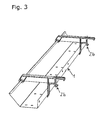
- Fig. 3
- eine weitere Ausführungsvariante in einer axonometrischen Darstellung;
- Fig. 4
- eine seitliche Ansicht der Ausführungsvariante von Fig. 3;
- Fig. 5
- das Halterungselement dieser Ausführungsvariante in einer axonometrischen Darstellung;
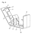
- Fig. 6
- einen Steckdosenhalter in einer axonometrischen Darstellung; und
- Fig. 7
- die Anbringung einer Kabelkette in einer axonometrischen Darstellung.
- Fig. 1
- a first embodiment in an axonometric representation;
- Fig. 2
- a side view of the embodiment of Fig. 1;
- Fig. 3
- a further embodiment in an axonometric representation;
- Fig. 4
- a side view of the embodiment of Fig. 3;
- Fig. 5
- the support member of this embodiment in an axonometric representation;
- Fig. 6
- a socket holder in an axonometric representation; and
- Fig. 7
- the attachment of a cable chain in an axonometric representation.
Die Ausführungsvariante von Fig. 1 besteht aus einer Kabelwanne 1 und mehreren Halterungselementen 2a. Wie aus Fig. 2 ersichtlich ist, weist die Kabelwanne 1 einen Bodenabschnitt 3 auf, der in Gebrauchslage waagrecht angeordnet ist. An einer Seite schließt an den Bodenabschnitt 3 ein schräg nach oben geneigter Abschnitt 4 an, der an seiner oberen Kante einen Falz 5 aufweist, der einwärts gebogen ist. Dem schräg nach oben geneigten Abschnitt 4 gegenüberliegend ist ein senkrechter Abschnitt 6 vorgesehen, in dem eine Reihe von Ausnehmungen 7 vorgesehen ist.The embodiment of Fig. 1 consists of a
Die Halterungselemente 2a bestehen jeweils aus einem Befestigungsabschnitt 8 und einem Tragarm 9. Der Befestigungsabschnitt 8 besteht im Wesentlichen aus einem vorderen Auflageabschnitt 10 und einem oberen Auflageabschnitt 11, die in einem rechten Winkel zueinander ausgebildet sind und die dazu bestimmt sind, auf einem andeutungsweise dargestellten Träger 14 mit rechteckigem Querschnitt aufzuliegen. Der vordere Auflageabschnitt 10 und der obere Auflageabschnitt 11 tragen an ihren Enden jeweils einen Einrastvorsprung 12, 13, die den Träger 14 umgreifen und das Halterungselement 2a in der Art einer Schnappverbindung fixieren.The mounting members 2a each consist of a mounting
An den Befestigungsabschnitt 8 schließt ein Distanzabschnitt 15 an, der aus einem oberen Flansch 16 und einem unteren Flansch 17 besteht, die seitlich an den vorderen Auflageabschnitt 10 anschließen und durch eine innere Rippe 18 miteinander verbunden sind.To the mounting
Dem vorderen Auflageabschnitt 10 gegenüberliegend schließt der Tragarm 9 an den Distanzabschnitt 15 an, der aus einem senkrechten Flansch 19, einem waagrechten Flansch 20 und einem schrägen Flansch 21 besteht. Unterhalb des Distanzabschnitts 15 ist am senkrechten Flansch 19 ein Rastelement 22 ausgebildet, das dazu dient, in eine Ausnehmung 7 der Kabelwanne 1 einzugreifen und diese zu halten. Dabei dient ein Vorderabschnitt 23 des schrägen Flanschs 21 als erster Halteabschnitt und der senkrechte Flansch 19 als zweiter Halteabschnitt. Die beiden Halteabschnitte 19, 23 sind durch elastische Verformung des Tragarms 9 elastisch gegeneinander bewegbar, so dass einerseits die Kabelwanne 1 sicher gelagert ist, aber andererseits ein leichter Zugang ermöglicht wird. Dabei wird das Rastelement 22 aus der Ausnehmung 7 herausgezogen, so dass die Kabelwanne 1 mit dem Falz 5 im Halteabschnitt 23 verbleibt und um die dadurch gebildete Achse nach unten schwenkt.The
In zusammengebautem Zustand bilden die Flansche 19, 20 und 21 Auflageflächen, die innen an der Kabelwanne 1 anliegen.When assembled, the
Der Tragarm 9 weist ein im Wesentlichen T-förmiges Profil auf, das einerseits durch die Flansche 19, 20 und 21 und andererseits durch Verstärkungsrippen 24 gebildet ist, die ihrerseits durch Stege 25 verstärkt sind. Ausnehmungen 26 in den Verstärkungsrippen 24 dienen zur Führung nicht dargestellter Kabel.The
Das Halterungselement 2b der Fig. 3 bis 5 besitzt einen Befestigungsabschnitt 8 und einen Distanzabschnitt 15, die ähnlich aufgebaut sind wie die der oben beschriebenen Ausführungsvariante. Der Tragarm 9 besitzt einen oberen Flansch 27, der sich geradlinig vom oberen Flansch 16 des Distanzabschnitts 15 fortsetzt.The
An seinem Ende trägt der Tragarm 9 einen ersten Halteabschnitt 23 mit einer Haltezunge 30, die von einer hohlzylindrischen Führungsfläche 31 umgeben ist. Der Abstand dazwischen dient zur gelenkigen Aufnahme des Falzes 5 der Kabelwanne 1.At its end, the
Weiters ist ein nach unten ragender Abschnitt 28 vorgesehen, der an seinem Ende ein nach innen ragendes Rastelement 29 trägt, das dazu vorgesehen ist, die Kabelwanne 1 zu untergreifen.Furthermore, a downwardly projecting portion 28 is provided, which carries at its end an inwardly projecting locking
An der Oberseite des Befestigungsabschnitts 8 ist eine Sicherungsrippe 35 vorgesehen, die dazu dient, sich an der Unterseite einer Tischplatte 36 abzustützen, wodurch verhindert wird, dass der Einrastvorsprung 13 auch bei großer Belastung vom Träger 14 abgezogen wird. Zur Montage oder Demontage des Halterungselements 2b muss daher die Tischplatte 36 verschoben oder entfernt werden.At the top of the mounting
Der Steckdosenhalter von Fig. 6 ist allgemein mit 40 bezeichnet und ähnlich wie der Tragarm 9 des Halterungselements 2a der ersten Ausführungsvariante von Fig. 1 und Fig. 2 ausgebildet.The socket holder of Fig. 6 is generally designated 40 and similar to the
In Fig. 7 ist die Anbringung einer Kabelkette 37 an einem Halterungselement 2a gezeigt, wobei sich die Kabelkette 37 bis in den Bodenbereich erstreckt und in einer Bodenhalterung 38 endet.In Fig. 7, the attachment of a
Die vorliegende Erfindung ermöglicht es, in einfacher und effizienter Weise ein Kabelführungssystem mit modularem Aufbau für Büromöbel zur Verfügung zu stellen.The present invention makes it possible to easily and efficiently provide a cable management system with a modular design for office furniture.
Claims (12)
Applications Claiming Priority (1)
| Application Number | Priority Date | Filing Date | Title |
|---|---|---|---|
| AT9702006A AT503544B1 (en) | 2006-06-06 | 2006-06-06 | DEVICE FOR MOUNTING CABLES FOR OFFICE FURNITURE |
Publications (1)
| Publication Number | Publication Date |
|---|---|
| EP1864591A1 true EP1864591A1 (en) | 2007-12-12 |
Family
ID=38229797
Family Applications (1)
| Application Number | Title | Priority Date | Filing Date |
|---|---|---|---|
| EP07079502A Withdrawn EP1864591A1 (en) | 2006-06-06 | 2007-05-24 | Device for mounting cables in office furnitures |
Country Status (2)
| Country | Link |
|---|---|
| EP (1) | EP1864591A1 (en) |
| AT (1) | AT503544B1 (en) |
Cited By (2)
| Publication number | Priority date | Publication date | Assignee | Title |
|---|---|---|---|---|
| WO2014063717A1 (en) * | 2012-10-25 | 2014-05-01 | Steelcase Werndl Ag | Furniture accessory in the form of a cable basket |
| WO2018101875A1 (en) * | 2016-11-29 | 2018-06-07 | Polstiernan Industri AB | An arrangement for attaching at least one accessory to a table, and a table comprising such an arrangement |
Citations (8)
| Publication number | Priority date | Publication date | Assignee | Title |
|---|---|---|---|---|
| DE2610939A1 (en) * | 1976-03-16 | 1977-09-29 | Selecta Organisation | Office desk with built-in electrical installations - has U-shaped cable ducts around side edges with drop down hinged access flaps |
| DE8027910U1 (en) * | 1980-10-18 | 1981-02-05 | Gesika-Bueromoebelwerk Gmbh & Co Kg, 4787 Geseke | WORK DESK, ESPECIALLY DESK |
| EP0179410A2 (en) * | 1984-10-22 | 1986-04-30 | August Fröscher GmbH & Co. K.G. | Table, in particular an interconnectible conference table |
| US4593505A (en) * | 1984-06-08 | 1986-06-10 | Westinghouse Electric Corp. | Panel base electrical raceway |
| NL9002265A (en) * | 1990-10-18 | 1992-05-18 | Ahrend Groep Nv | Cable channel for mounting under computer tables - has segregated cable channels and clips to affix to frame under table top |
| EP0797941A2 (en) * | 1996-03-25 | 1997-10-01 | CEKA-BÜROMÖBEL WERKE C. KRAUSE UND SOHN GmbH & Co. KG | Table, in particular for office workstations |
| US5971509A (en) * | 1996-05-17 | 1999-10-26 | Steelcase Inc. | Modular power and cable distribution system |
| JP2006102380A (en) * | 2004-10-08 | 2006-04-20 | Okamura Corp | Table with wiring duct |
Family Cites Families (4)
| Publication number | Priority date | Publication date | Assignee | Title |
|---|---|---|---|---|
| WO1996012423A1 (en) * | 1994-10-20 | 1996-05-02 | Flötotto Einrichtungssysteme Gmbh & Co. Kg | Table |
| JP4027480B2 (en) * | 1997-11-28 | 2007-12-26 | 株式会社岡村製作所 | Desk wiring duct device |
| JP2002262432A (en) * | 2001-02-28 | 2002-09-13 | Askul Corp | Electric wire holding duct |
| JP3793530B2 (en) * | 2003-10-03 | 2006-07-05 | 星和電機株式会社 | Hanging wiring duct |
-
2006
- 2006-06-06 AT AT9702006A patent/AT503544B1/en not_active IP Right Cessation
-
2007
- 2007-05-24 EP EP07079502A patent/EP1864591A1/en not_active Withdrawn
Patent Citations (8)
| Publication number | Priority date | Publication date | Assignee | Title |
|---|---|---|---|---|
| DE2610939A1 (en) * | 1976-03-16 | 1977-09-29 | Selecta Organisation | Office desk with built-in electrical installations - has U-shaped cable ducts around side edges with drop down hinged access flaps |
| DE8027910U1 (en) * | 1980-10-18 | 1981-02-05 | Gesika-Bueromoebelwerk Gmbh & Co Kg, 4787 Geseke | WORK DESK, ESPECIALLY DESK |
| US4593505A (en) * | 1984-06-08 | 1986-06-10 | Westinghouse Electric Corp. | Panel base electrical raceway |
| EP0179410A2 (en) * | 1984-10-22 | 1986-04-30 | August Fröscher GmbH & Co. K.G. | Table, in particular an interconnectible conference table |
| NL9002265A (en) * | 1990-10-18 | 1992-05-18 | Ahrend Groep Nv | Cable channel for mounting under computer tables - has segregated cable channels and clips to affix to frame under table top |
| EP0797941A2 (en) * | 1996-03-25 | 1997-10-01 | CEKA-BÜROMÖBEL WERKE C. KRAUSE UND SOHN GmbH & Co. KG | Table, in particular for office workstations |
| US5971509A (en) * | 1996-05-17 | 1999-10-26 | Steelcase Inc. | Modular power and cable distribution system |
| JP2006102380A (en) * | 2004-10-08 | 2006-04-20 | Okamura Corp | Table with wiring duct |
Cited By (5)
| Publication number | Priority date | Publication date | Assignee | Title |
|---|---|---|---|---|
| WO2014063717A1 (en) * | 2012-10-25 | 2014-05-01 | Steelcase Werndl Ag | Furniture accessory in the form of a cable basket |
| CN104754986A (en) * | 2012-10-25 | 2015-07-01 | Steelcase韦恩德尔办公家具股份公司 | Furniture accessory in the form of a cable basket |
| US9364080B2 (en) | 2012-10-25 | 2016-06-14 | Steelcase Werndl Ag | Furniture accessory in the form of a cable basket |
| CN104754986B (en) * | 2012-10-25 | 2017-04-26 | 斯蒂尔凯斯有限公司 | furniture accessory in the form of a cable basket |
| WO2018101875A1 (en) * | 2016-11-29 | 2018-06-07 | Polstiernan Industri AB | An arrangement for attaching at least one accessory to a table, and a table comprising such an arrangement |
Also Published As
| Publication number | Publication date |
|---|---|
| AT503544B1 (en) | 2007-11-15 |
| AT503544A4 (en) | 2007-11-15 |
Similar Documents
| Publication | Publication Date | Title |
|---|---|---|
| DE102004048770B4 (en) | Housing arrangement with at least two junction boxes | |
| EP0297400B1 (en) | Office work station | |
| EP0845168A1 (en) | Cable channel section | |
| EP3015030A1 (en) | Device for supplying electric power to power consumers arranged on a shelf | |
| CH714203A1 (en) | Device for presenting goods and adapters for such a device. | |
| EP0702441A1 (en) | Electrical installation apparatus, especially for cable ducts | |
| AT503544B1 (en) | DEVICE FOR MOUNTING CABLES FOR OFFICE FURNITURE | |
| DE3303764A1 (en) | ELECTRICAL INSTALLATION DEVICE | |
| DE102007059204A1 (en) | Switch cabinet or rack, has side walls comprising end sections at lower and/or upper boundary region, where supports of base and/or cover are inserted into end sections and secured by securing elements | |
| EP3461963B1 (en) | Supporting construction system and system of connecting elements for the supporting construction | |
| DE19818269A1 (en) | Diagonal insertion system | |
| DE102016124609A1 (en) | Distribution box for installation in a wall opening | |
| EP1394915B1 (en) | Cable guide | |
| DE3939967C2 (en) | ||
| DE102009020726A1 (en) | Supply system for providing a media supply | |
| EP2645501B2 (en) | System arrangement consisting of a system support piece and several system modules for electro-installation technology for buildings and door communication technology | |
| DE202008010414U1 (en) | Lighting element in shopfitting or presentation systems | |
| DE4400828C2 (en) | Bathroom cabinet with a plastic case | |
| EP0430271B1 (en) | Gridsystem for suspension ceiling | |
| EP1359650A1 (en) | Connection device for an electric distribution installation | |
| CH712397B1 (en) | Distribution module arrangement with a conductor guide bridge. | |
| EP2043215B1 (en) | Conductive channel with mounting device | |
| DE10218128C1 (en) | Electrical distributor for lamp fitting secured in opening in wall of lamp fitting housing via cooperating upper and lower clamp parts | |
| EP0825381B1 (en) | Housing for lamp socket in light fixture housings | |
| EP0696098A1 (en) | Coupling device for cable ducts |
Legal Events
| Date | Code | Title | Description |
|---|---|---|---|
| PUAI | Public reference made under article 153(3) epc to a published international application that has entered the european phase |
Free format text: ORIGINAL CODE: 0009012 |
|
| AK | Designated contracting states |
Kind code of ref document: A1 Designated state(s): AT BE BG CH CY CZ DE DK EE ES FI FR GB GR HU IE IS IT LI LT LU LV MC MT NL PL PT RO SE SI SK TR |
|
| AX | Request for extension of the european patent |
Extension state: AL BA HR MK YU |
|
| 17P | Request for examination filed |
Effective date: 20080606 |
|
| 17Q | First examination report despatched |
Effective date: 20080717 |
|
| AKX | Designation fees paid |
Designated state(s): AT BE BG CH CY CZ DE DK EE ES FI FR GB GR HU IE IS IT LI LT LU LV MC MT NL PL PT RO SE SI SK TR |
|
| STAA | Information on the status of an ep patent application or granted ep patent |
Free format text: STATUS: THE APPLICATION IS DEEMED TO BE WITHDRAWN |
|
| 18D | Application deemed to be withdrawn |
Effective date: 20081128 |