EP1867932A2 - Automatic displacement ventilation system with heating mode - Google Patents
Automatic displacement ventilation system with heating mode Download PDFInfo
- Publication number
- EP1867932A2 EP1867932A2 EP07115479A EP07115479A EP1867932A2 EP 1867932 A2 EP1867932 A2 EP 1867932A2 EP 07115479 A EP07115479 A EP 07115479A EP 07115479 A EP07115479 A EP 07115479A EP 1867932 A2 EP1867932 A2 EP 1867932A2
- Authority
- EP
- European Patent Office
- Prior art keywords
- air
- register
- displacement
- mixing
- flow
- Prior art date
- Legal status (The legal status is an assumption and is not a legal conclusion. Google has not performed a legal analysis and makes no representation as to the accuracy of the status listed.)
- Granted
Links
- 238000009423 ventilation Methods 0.000 title claims abstract description 90
- 238000010438 heat treatment Methods 0.000 title claims abstract description 50
- 238000006073 displacement reaction Methods 0.000 title abstract description 107
- 238000001816 cooling Methods 0.000 claims description 31
- 230000003750 conditioning effect Effects 0.000 abstract description 3
- 230000000694 effects Effects 0.000 description 9
- 208000029152 Small face Diseases 0.000 description 7
- 230000005540 biological transmission Effects 0.000 description 7
- 230000007480 spreading Effects 0.000 description 7
- 239000000356 contaminant Substances 0.000 description 6
- 238000013022 venting Methods 0.000 description 5
- 230000008859 change Effects 0.000 description 4
- 230000001143 conditioned effect Effects 0.000 description 4
- 230000007246 mechanism Effects 0.000 description 4
- 238000000034 method Methods 0.000 description 3
- 230000009471 action Effects 0.000 description 2
- 238000011109 contamination Methods 0.000 description 2
- 238000009826 distribution Methods 0.000 description 2
- 239000000463 material Substances 0.000 description 2
- 238000013517 stratification Methods 0.000 description 2
- UGFAIRIUMAVXCW-UHFFFAOYSA-N Carbon monoxide Chemical compound [O+]#[C-] UGFAIRIUMAVXCW-UHFFFAOYSA-N 0.000 description 1
- 208000027418 Wounds and injury Diseases 0.000 description 1
- 230000009286 beneficial effect Effects 0.000 description 1
- 229910002091 carbon monoxide Inorganic materials 0.000 description 1
- 230000001351 cycling effect Effects 0.000 description 1
- 230000006378 damage Effects 0.000 description 1
- 230000001419 dependent effect Effects 0.000 description 1
- 238000001514 detection method Methods 0.000 description 1
- 238000009792 diffusion process Methods 0.000 description 1
- 230000005611 electricity Effects 0.000 description 1
- 230000020169 heat generation Effects 0.000 description 1
- 208000014674 injury Diseases 0.000 description 1
- 229910052751 metal Inorganic materials 0.000 description 1
- 239000002184 metal Substances 0.000 description 1
- 230000002085 persistent effect Effects 0.000 description 1
- 230000008569 process Effects 0.000 description 1
- 230000003134 recirculating effect Effects 0.000 description 1
- 230000004044 response Effects 0.000 description 1
- 230000000630 rising effect Effects 0.000 description 1
Images


Classifications
-
- F—MECHANICAL ENGINEERING; LIGHTING; HEATING; WEAPONS; BLASTING
- F24—HEATING; RANGES; VENTILATING
- F24F—AIR-CONDITIONING; AIR-HUMIDIFICATION; VENTILATION; USE OF AIR CURRENTS FOR SCREENING
- F24F1/00—Room units for air-conditioning, e.g. separate or self-contained units or units receiving primary air from a central station
- F24F1/0007—Indoor units, e.g. fan coil units
- F24F1/0059—Indoor units, e.g. fan coil units characterised by heat exchangers
- F24F1/0067—Indoor units, e.g. fan coil units characterised by heat exchangers by the shape of the heat exchangers or of parts thereof, e.g. of their fins
-
- F—MECHANICAL ENGINEERING; LIGHTING; HEATING; WEAPONS; BLASTING
- F24—HEATING; RANGES; VENTILATING
- F24F—AIR-CONDITIONING; AIR-HUMIDIFICATION; VENTILATION; USE OF AIR CURRENTS FOR SCREENING
- F24F11/00—Control or safety arrangements
- F24F11/70—Control systems characterised by their outputs; Constructional details thereof
- F24F11/72—Control systems characterised by their outputs; Constructional details thereof for controlling the supply of treated air, e.g. its pressure
- F24F11/74—Control systems characterised by their outputs; Constructional details thereof for controlling the supply of treated air, e.g. its pressure for controlling air flow rate or air velocity
-
- F—MECHANICAL ENGINEERING; LIGHTING; HEATING; WEAPONS; BLASTING
- F24—HEATING; RANGES; VENTILATING
- F24F—AIR-CONDITIONING; AIR-HUMIDIFICATION; VENTILATION; USE OF AIR CURRENTS FOR SCREENING
- F24F11/00—Control or safety arrangements
- F24F11/30—Control or safety arrangements for purposes related to the operation of the system, e.g. for safety or monitoring
-
- F—MECHANICAL ENGINEERING; LIGHTING; HEATING; WEAPONS; BLASTING
- F24—HEATING; RANGES; VENTILATING
- F24F—AIR-CONDITIONING; AIR-HUMIDIFICATION; VENTILATION; USE OF AIR CURRENTS FOR SCREENING
- F24F11/00—Control or safety arrangements
- F24F11/70—Control systems characterised by their outputs; Constructional details thereof
- F24F11/72—Control systems characterised by their outputs; Constructional details thereof for controlling the supply of treated air, e.g. its pressure
- F24F11/74—Control systems characterised by their outputs; Constructional details thereof for controlling the supply of treated air, e.g. its pressure for controlling air flow rate or air velocity
- F24F11/755—Control systems characterised by their outputs; Constructional details thereof for controlling the supply of treated air, e.g. its pressure for controlling air flow rate or air velocity for cyclical variation of air flow rate or air velocity
-
- F—MECHANICAL ENGINEERING; LIGHTING; HEATING; WEAPONS; BLASTING
- F24—HEATING; RANGES; VENTILATING
- F24F—AIR-CONDITIONING; AIR-HUMIDIFICATION; VENTILATION; USE OF AIR CURRENTS FOR SCREENING
- F24F13/00—Details common to, or for air-conditioning, air-humidification, ventilation or use of air currents for screening
- F24F13/08—Air-flow control members, e.g. louvres, grilles, flaps or guide plates
- F24F13/082—Grilles, registers or guards
-
- F—MECHANICAL ENGINEERING; LIGHTING; HEATING; WEAPONS; BLASTING
- F24—HEATING; RANGES; VENTILATING
- F24F—AIR-CONDITIONING; AIR-HUMIDIFICATION; VENTILATION; USE OF AIR CURRENTS FOR SCREENING
- F24F7/00—Ventilation
- F24F7/04—Ventilation with ducting systems, e.g. by double walls; with natural circulation
- F24F7/06—Ventilation with ducting systems, e.g. by double walls; with natural circulation with forced air circulation, e.g. by fan positioning of a ventilator in or against a conduit
-
- F—MECHANICAL ENGINEERING; LIGHTING; HEATING; WEAPONS; BLASTING
- F24—HEATING; RANGES; VENTILATING
- F24F—AIR-CONDITIONING; AIR-HUMIDIFICATION; VENTILATION; USE OF AIR CURRENTS FOR SCREENING
- F24F2110/00—Control inputs relating to air properties
- F24F2110/10—Temperature
- F24F2110/12—Temperature of the outside air
-
- F—MECHANICAL ENGINEERING; LIGHTING; HEATING; WEAPONS; BLASTING
- F24—HEATING; RANGES; VENTILATING
- F24F—AIR-CONDITIONING; AIR-HUMIDIFICATION; VENTILATION; USE OF AIR CURRENTS FOR SCREENING
- F24F2110/00—Control inputs relating to air properties
- F24F2110/50—Air quality properties
-
- F—MECHANICAL ENGINEERING; LIGHTING; HEATING; WEAPONS; BLASTING
- F24—HEATING; RANGES; VENTILATING
- F24F—AIR-CONDITIONING; AIR-HUMIDIFICATION; VENTILATION; USE OF AIR CURRENTS FOR SCREENING
- F24F2110/00—Control inputs relating to air properties
- F24F2110/50—Air quality properties
- F24F2110/64—Airborne particle content
Abstract
Description
- The invention relates to an occupied space ventilation system according to the pre-characterizing part of claim 1.
- From
EP 1 323 988 a system for ventilation of a room is known, wherein at least one supply air means is arranged to supply clean supply air to the room, and wherein at least one air discharge means is arranged to remove used indoor air from the room. The respective air flows through the supply means and discharge means are controlled so as to provide a clean air zone in a specific part of the room. The air supply means can be located at the floor of the room to be ventilated, while the air discharge means can be located close to the ceiling. - From
US 2 928 330 a process and means for heating, cooling and distribution of preconditioned air into several rooms through ventilators in their walls is known. - From
DE 40 07 418 another ventilation and/or air condition system is known. - It is an object of the invention to provide an improved occupied space ventilation system allowing to control the flow of heated or cooled air, and to control the temperature distribution within the room better, particularly taking into consideration whether the system works in the heating or cooling mode.
- This is achieved by the features in claim 1. Preferred embodiments are described in the dependent claims 2 to 4.
- Embodiments of the invention and systems not belonging to the invention for general reference are described in the following description of the drawings as follows:
- Figs. 1A and 1B illustrate a conditioned space with configurable mixing/displacement ventilation registers in displacement and mixing modes, respectively.
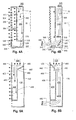
- Figs. 2A and 2B illustrate a first embodiment of a configurable mixing/displacement ventilation register in displacement and mixing modes, respectively.
- Figs. 3A and 3B illustrate a second embodiment of a configurable mixing/displacement ventilation register in displacement and mixing modes, respectively.
- Figs. 4A and 4B illustrate a third embodiment of a configurable mixing/displacement ventilation register in displacement and mixing modes, respectively.
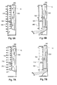
- Figs. 5A and 5B illustrate a fourth embodiment of a configurable mixing/displacement ventilation register in displacement and mixing modes, respectively.
- Figs. 6A and 6B illustrate a fifth embodiment of a configurable mixing/displacement ventilation register in displacement and mixing modes, respectively.
- Figs. 7A and 7B illustrate a sixth embodiment of a configurable mixing/displacement ventilation register in displacement and mixing modes, respectively.
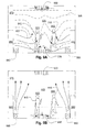
- Figs. 8A and 8B illustrate an alternative embodiment in which the return registers are changed over from heating to cooling mode, but the supply registers are the same.
- Figs. 9A and 9B illustrate an alternative embodiment in which the return registers are changed over from heating to cooling mode, and hydronic heating is used in place of force air heating.
- Fig. 10 is an illustration of a central control system that may be used with various embodiments discussed herein.
- Fig. 11 shows a plan view of a room with
multiple discharge registers - Figs. 12A and 12B show an embodiment of a configurable mixing/displacement ventilation register in displacement and mixing modes, respectively, in which independent dampers are used to modulate total air volume, for example based on a VAV scheme.
- Fig. 13 illustrates a simple example of a controller for VAV control as well as mode switching for a configurable mixing/displacement ventilation register such as illustrated at Figs. 12A and 12B.
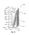
- Fig. 14 illustrates seventh embodiment of a configurable mixing/displacement ventilation register.
- These figures are intended to show the concept and are not intended to show details of components whose designs are well understood in the field such as linkages, motor details, bearings, supports, etc. These are within the competence of skilled practitioners and are not discussed in detail herein.
- Figure 1A and Figure 1B illustrate a configurable mixing/
displacement ventilation register 550 in an occupiedroom 570.People 510 in the room are warmer than the surrounding air, causing air to rise by convection. The room also contains a cooling-mode return register 530 in the upper portion of the room, and a heatingmode return register 535 in the lower portion of the room. The temperature of the air within theroom 570 is illustrated -by isothermal layers ofconstant temperature air 505. - When the room is in displacement mode, which is generally used for cooling the conditioned space, the mixing/
displacement ventilation register 550 supplies cooled air at a low velocity from a relatively high portion and over a relatively large face area of the mixing/displacement ventilation register 550. This cool air flows along the lower portion of the room. Any heat source within the room such as theoccupants 510, causes air warmed by that source to rise by convective forces resulting in warm zones indicated by dips in contours ofconstant temperature 515. This rising air draws fresh cool air pooled near afloor 521 to replace the polluted and stale air surrounding theoccupants 510. The warm air pools near the ceiling and is withdrawn by thereturn register 530. The higher regions of theroom 570 remain relatively undisturbed and since it is not within the lower part of the room - the inhabited space - the air in contact with and breathed by occupants is relatively fresh. By not cooling this uninhabited space, the cooling efficiency is increased. Also, the immediate replacement of air polluted by heat sources increases comfort. - Figure 1B illustrates the mixing mode for heating the occupied space. In this mode, the mixing/
displacement ventilation register 550 supplies heated air at a high velocity through a relatively small face area as illustrated byjets 551. This warm air flows rapidly along the lower portion of the room before it has time to rise from convection and encourages mixing of all the air in the room, as indicated by the randomly arranged and directedarrows 552. This rapid movement causes mixing of the air in the room due to the initial velocity of thejets 551, their turbulence, and the tendency of the heated air naturally to rise due to convection. The heatingmode return register 535 removes cooled air which tends to sink from convection. - Figure 2A and Figure 2B illustrate a first embodiment of a configurable mixing/
displacement ventilation register 550 in displacement and mixing modes, respectively. Referring now to Fig. 2A the first embodiment of a configurable mixing/displacement ventilation register 550 is in displacement, or cooling, mode. As thecool air 160 enters theventilation register plenum 130 it causes athermal actuator 105 to move athrust rod 110 attached to abaffle cage 115 toward alower section 120 of the configurable mixing/displacement ventilation register 550, thereby moving it to thefloor base 150 of the configurable mixing/displacement ventilation register 550. Thebaffle cage 115 allows air to pass through it and serves to spread the flow over the large face area that includes alarger baffle housing 100 of the configurable mixing/displacement ventilation register 550. The open area of thebaffles baffles incoming flow 160 broadly over the face area of thebaffles outer diffusion baffle 100 of the configurable mixing/displacement ventilation register 550 as indicated byarrows 145. The air flowing from thebaffle cage 115 and thebaffle housing 110 therefore functions as displacement supply register venting air at a low velocity through relatively restrictive openings in the baffles of thebaffle housing 100 and thebaffle cage 115. - Figure 2B illustrates the first embodiment in mixing, or heating, mode. As the
warm air 165 enters theventilation register plenum 135 it causesthermal actuator 105 to move thebaffle cage 115 upwardly to uncover anopen outlet 120 of the configurable mixing/displacement ventilation register 550. A bottom 116 of thebaffle cage 115 has a high percentage open area and provides little resistance to flow as does theopen outlet 120. As a result, a direct flow path through theplenum 135 to theopen outlet 120 is created which results in low restriction - high velocity - flow of the warm air to theopen outlet 120. Thus, most of theheating air 165 passes at a relatively high velocity out the lower, relatively small face area of theopen outlet 120 of the configurable mixing/displacement ventilation register 550. Thus, in the present configuration, it functions as a mixing supply register. - Figure 3A and Figure 3B illustrate a second embodiment of a configurable mixing/displacement ventilation register in displacement and mixing modes, respectively. Figure 3A illustrates the second embodiment of the configurable mixing/
displacement ventilation register 551 in displacement, or cooling mode. Atransmission 15 is indicated figuratively by a broken line. The transmission may be formed by any suitable means such as a pulley or gear system or by means of pushing or pulling or other rotating members. The details are outside the scope of invention and are readily created for various design arrangements. - As
cool air 160 enters aventilation register plenum 230 it causes thethermal actuator 10, by way of thetransmission 15, to rotate a spring loadedcapstan 220 which releases tension on achord 225 allowing a spring-loadedcap plate 210 to pivot on an axis of the capstan/lever 215 to seal the end 212 of theventilation register plenum 230.Cool air flow 270 is forced to spread the flow over the large face area of a flow-restrictingbaffle 250 and further distributed by anouter baffle 260. Thecapstan 220 also releases tension on alower pull cord 235 releasing a spring loadedbaffle panel 245 to pivot on a spring-loadedaxel 240, securing it flush with theouter baffle 260 of the configurable mixing/displacement ventilation register 551. - Note that the
transmission 15 and the pulley and capstan components are shown for illustration purposes only and can be replaced by any suitable mechanism for performing the described functions. These mechanisms could be mechanical or electromechanical and performed by means of a thermoactuator such as a wax motor or a linear actuator powered by electricity or pneumatic power or controls. There are many possible design variations and the details are unimportant for understanding the invention so they are not discussed at length here. Note also that the views of the present, foregoing, and further embodiments below are section views of suitable enclosures. They can be rectangular or other shapes. The materials used may be any combination of metal, plastic, or other materials suitable for conveying air. - The resulting configuration illustrated in Figure 3A allows the
cool air 165 to flow through theouter baffle 260 of the configurable mixing/displacement ventilation register 551 in the manner of a displacement supply register. The open area of thebaffle 260 is such as to cause resistance across the face of thebaffle 260 and thebaffle panel 245 thereby spreading theflow 160 broadly over theouter baffle 260 face area of the configurable mixing/displacement ventilation register 551 as indicated byarrows 265. It therefore functions as displacement supply register, venting air at a low velocity through relatively restrictive openings of theouter baffle 260 and thebaffle panel 245. - Figure 3B illustrates the second embodiment of the configurable mixing/
displacement ventilation register 551 in mixing, or heating mode. As theheated air 165 enters theventilation register plenum 230 it causes thethermal actuator 10 to act through thetransmission 15 to rotate the spring-loadedcapstan 220, exerting tension on the capplate pull cord 225 causing the spring-loadedcap plate 210 to pivot on theaxel 215 and open the end 212 of theplenum 230. Thecapstan 220 also exerts tension on thelower pull cord 235 causing the spring loadedbaffle panel 245 to pivot on theaxis 240, opening the lower portion of the configurable mixing/displacement ventilation register 551. As a result, most of theheated air 165 passes at a relatively high velocity out the lower, relatively small face area of an open outlet 243 of the configurable mixing/displacement ventilation register 551 so that it functions as a mixing supply register. - Figure 4A and Figure 4B illustrate a third embodiment of a configurable mixing/
displacement ventilation register 552 in displacement and mixing modes, respectively. Figure 4A illustrates the third embodiment of the configurable mixing/displacement ventilation register 552 in the displacement, or cooling, mode. As thecool air 160 enters theventilation register plenum 330 it causes thethermal actuator 10 to act upon thetransmission 15 to rotate a spring loadedcapstan 320 which releases tension on achord 325 allowing a spring-loadedcap plate 310 to pivot on an axis of capstan/lever 315 to seal the end 312 of aplenum 330.Cool air flow 370 is forced to spread over the large face area of a flow-restrictingbaffle 350. Thecapstan 320 also releases tension on alower pull cord 335 releasing a spring loadedbaffle panel 345 to pivot on anaxel 340, securing it flush with anouter baffle 304 of the configurable mixing/displacement ventilation register 552. The releasing of the spring loadedbaffle panel 345 also releases tension on athird pull chord 345 allowing a slidingbaffle panel 306 to align with theouter baffle 304 allowing acool air flow 370 flow through the large face area of the twobaffle panels - The resulting configuration illustrated in Figure 4A allows the
cool air 160 to flow through the baffle/grate 322A of the configurable mixing/displacement ventilation register 552 in the manner of a displacement supply register. The open area of the baffle/grate 322 may be such as to cause substantial or little resistance across the face of the baffle/grate 322. The spreading of the flow may be provided by theinner baffle 350 or the outer baffle/grate 322 may assist by providing some resistance as well. By spreading the flow broadly over the face area of the configurable mixing/displacement ventilation register 552 as indicated by thearrows 365, it functions as displacement supply register. - Figure 4B illustrates the third embodiment of the configurable mixing/
displacement ventilation register 552 in mixing, or heating, mode. As theheated air 165 enters theventilation register plenum 330, it causes thethermal actuator 10 to act upon thetransmission 15 to rotate the spring loadedcapstan 320 causing it to exert tension on the capplate pull cord 325. This causes the spring-loadedcap plate 310 to pivot on theaxel 315 and open the end of theplenum 330. Thecapstan 320 also exerts tension on thelower pull cord 335 causing the spring loadedbaffle panel 345 to pivot on theaxis 340, opening the lower portion of the configurable mixing/displacement ventilation register 552. The pivoting of the spring loadedbaffle panel 345 also removes tension on thethird pull chord 345 allowing the slidingbaffle panel 306 to close the baffle/shutter 322 preventing thewarm air flow 330 from passing through it. Theheated air 165 thus passes at a relatively high velocity out the lower, relatively small face area of anopen outlet 343 of the configurable mixing/displacement ventilation register 552 so that the configurable mixing/displacement ventilation register 552 functions as a mixing supply register. - Figure 5A and Figure 5B illustrate a fourth embodiment of a configurable mixing/displacement ventilation register 553 in displacement and mixing modes, respectively. Figure 5A illustrates the displacement, or cooling mode. As the
cool air 160 enters a ventilation register plenum 425 it causes a rotating athermal actuator capstan 450 to act upon apull chord 455 to rotate a spring loadedflap cover 440 on apivot 460 to seal offplenum 430. This action causes the cooledair 160 to enter only acooling plenum 405 which is separated from aheating plenum 430 by amiddle wall 435. The open area of the baffle 404 is such as to cause resistance across the face of the baffle 404 thereby spreading theflow 160 broadly over the large face area of the configurable mixing/displacement ventilation register 553. This causes it to function as a displacement supply register venting air at a low velocity over a large area. - Figure 5B illustrates the fourth embodiment of the configurable mixing/displacement ventilation register 553 in mixing, or heating, mode. As the
warm air 165 enters the ventilation register plenum 425 it causes the rotatingthermal actuator capstan 450 to act upon thepull chord 455 to rotate the spring loadedflap cover 440 on thepivot 460 to seal off thecooling plenum 405. This action causes thewarm air 165 to enter only thewarm plenum 430 which is bound by themiddle wall 435 and aback wall 420. The relatively smaller face area of a heating mode outlet 475 builds greater back pressure within the warm (heating)plenum 430 causing theflow 160 to exit through the small face area of the outlet 475 of the configurable mixing/displacement ventilation register 553 at high velocity. As a result, the register 553 functions as a mixing supply register. - Figure 6A and Figure 6B illustrate a fifth embodiment of a configurable mixing/displacement ventilation register 554 in displacement and mixing modes, respectively. Figure 6A illustrates the fifth embodiment in displacement, or cooling, mode. As the
cool air 160 enters a ventilation register aplenum 630 it causes thethermal actuator 10 to act upon a push rod 620 to rotate a cap plate 610 on a pivot 615 to seal the end of theplenum 630.Cool air flow 665 is forced to spread over the large face area of a flow-restrictinginner baffle 650 and into acooling plenum 605. The movement of the cap plate 610 also releases tension on a lower baffle panel 645 to pivot on an axel 640, securing it flush with an outer baffle 604 which forces acool air flow 665 to spread over the large face area of a flow-restricting baffle 604. - The resulting configuration illustrated in Figure 6A allows the
cool air 630 to flow through the flow-restrictinginner baffle 650 then an outer baffle 604 of the configurable mixing/displacement ventilation register 554 in the manner of a displacement supply register. The open area of the baffle 604 is such as to cause resistance across the face of the baffle 604 and lower baffle panel 645 thereby spreading theflow 665 broadly over the face area of the configurable mixing/displacement ventilation register 554 as indicated by thearrows 665 and therefore functions as displacement supply register venting air at a low velocity through relatively restrictive openings within the outer baffles 604 and the baffle panel 645. - Figure 6B illustrates the fifth embodiment of the configurable mixing/displacement ventilation register 554 in mixing, or heating mode. As the
heated air 165 enters theventilation register plenum 630 it causes thethermal actuator 10 to act upon the push rod 620 to rotate the cap plate 610 on the pivot 615 to open the end of theplenum 630. This causes engagement of the cap plate 610 and a lever arm 655 of the baffle panel 645 to swing the baffle panel 645 in an open position, opening the lower portion of the configurable mixing/displacement ventilation register 554. As a result, theheated air 165 passes at a relatively high velocity out the lower, relatively small face area of an open outlet 643 of the configurable mixing/displacement ventilation register 554 so that it functions as a mixing supply register. - Figure 7A and Figure 7B illustrate a sixth embodiment of a configurable mixing/displacement ventilation register in displacement and mixing modes, respectively. Figure 7A illustrates the sixth embodiment in displacement, or cooling, mode. Note the present embodiment is similar to the embodiment of Figure 6A and Figure 6B so many of the reference numerals are common. As the
cool air 160 enters theventilation register plenum 630 it causes thethermal actuator 10 to act upon the push rod 620 to rotate the cap plate 610 on the pivot 615 to seal the end of theplenum 630. Thecool air flow 160 is forced to spread over the large face area of the flow-restrictinginner baffle 650 and into thecooling plenum 605. The resulting configuration illustrated in Figure 7A allows thecool air 630 to flow through the flow-restrictinginner baffle 650 then the very openouter baffle 700 of the configurable mixing/displacement ventilation register 555 in the manner of a displacement supply register. The resistance across the face of thebaffle 650 is such as to cause resistance across the face of thebaffle 650 thereby spreading theflow 750 broadly over the face area of thebaffle 650 and out through thelow restriction baffle 700 as indicated by thearrows 710 and therefore functions as displacement supply register venting air at a low velocity through relatively restrictive openings within theinner baffles 650 and theopen baffle panel 700. - Figure 7B illustrates the sixth embodiment of the configurable mixing/displacement ventilation register 555 in mixing, or heating mode. As the
heated air 165 enters theventilation register plenum 630 it causes thethermal actuator 10 to act upon the push rod 620 to rotate the cap plate 610 on the pivot 615 to open the end of theplenum 630. Theheated air 165 thus predominately passes at a relatively high velocity out the lower, relatively small face area of an open outlet 643 of the configurable mixing/displacement ventilation register 555 so that it functions as a mixing supply register. - Figure 8A and Figure 8B illustrate an alternative embodiment in which the return registers are changed over from heating to cooling mode, but the supply registers are in the same configuration in both heating and cooling mode. Displacement registers 850 are located in a
room 850. Displacement registers 850 are normal displacement registers installed in a system in which return air registers 830 and 835 exist. During cooling mode, the displacement registers 850 deliver cool air at floor level as illustrated and warm air stratified near the ceiling is returned via return registers 830. As in previous embodiments, displacement supply air flow near thefloor 821 and is heated byoccupants 810 causingthermal plumes 815 which are indicated byisothermal lines 805.Warm air 870 near the ceiling is drawn into the return air register and 830. Anair recirculating fan 831, may optionally be provided to mix warm stratified air in the heating mode. Thefan 831 may positioned at any point in a room including near the floor or in the middle. Note that where mixing is used, return registers at only one level may suffice, for example, only one set of return registers may be used such as those near theceiling 830 or ones located at an intermediate height (not illustrated). The circulatingfan 831 may be controlled locally using a sensor for detecting either cold temperatures near the floor, warm air near the ceiling, or a floor-ceiling differential temperature. - Figure 8B illustrates the alternative embodiment of the conventional
displacement ventilation register 850 in a heating mode. Heated air enters theroom 820 at low velocity and rises. A return register located near the floor draws cooled air in. By arranging the return registers at a position remote from the displacement registers 850, a circulation pattern can be established in the room that mitigates the undesirable stratification that can occur when using non-mixing type supply registers during heating. - Figure 9A and Figure 9B illustrate an alternative embodiment in which the return registers are changed over from heating to cooling mode, and hydronic heating is used in place of force air heating. In the present embodiment, heating is done with a separate heating system under common control, for example hydronic heating using
hydronic heaters 980. Displacement registers 950 are normal displacement registers installed in a system in which return air registers 930 and 935 exist. During cooling mode, the displacement registers 950 deliver cool air at floor level as illustrated and warm air stratified near the ceiling is returned via return registers 930. As in previous embodiments, displacement supply air flow near the floor and is heated byoccupants 915.Warm air 970 near the ceiling is drawn into the return air register and 930. - Figure 9B illustrates an alternative embodiment of the conventional
displacement ventilation register 850 in a heating mode. Heated air enters the room from hydronic heaters. Areturn register 935 located near the floor draws cooled air in. By arranging the return registers at a position remote from thehydronic heaters 980, a circulation pattern can be established in the room that mitigates the undesirable stratification that can occur when using non-mixing type supply registers during heating. - In many commercial buildings, heat may be lost through only one or two walls of an occupied space. For example, in an office building this is commonly the case. In a preferred embodiment of the general Figure 9B embodiment, the rear wall in which at least one of the return registers 935 is located corresponds to that wall. This is so that the coldest air, which may be flowing downwardly along the surface of the "cold" wall, can be drawn into the one or more return registers 935 rather than mixing with the room air or causing the lower stratum of the room to get colder. The volume exchange rate may be sized to match the volume rate of the convective flow, which is readily predicted based on the outdoor air temperature, the conductivity and diffusivity of the wall, the film coefficients and so on according to known techniques. This is an excellent application for feed-forward or predictive model-based control because of the unsteady state of the wall system. In a preferred embodiment, such a model-based control scheme may take account of outdoor wind speed and direction, in addition to the obvious one of air temperature. In addition, such preferred embodiment may take account of conditioned space occupancy and predicted activity levels (for example, a lookup table based on time of day) so that activity-induced disturbances in the thermal convection field can be taken into account.
- Obviously, a feed-forward scheme would not necessarily explicitly perform all such computations, for example, modeling the real-time temperature of the wall resulting from internal capacity and so on. But any control system controlling air exchanges based on the thermal flow from a cold wall would tend to exchange more air when it is colder outside than when it is less cold. This makes the air changes independent of the load, which for a given outdoor temperature (and possibly other conditions, as discussed), may vary depending on the activity level, which can add additional heat generation to the system (e.g. office machinery, lights, etc.). In addition, many commercial building heating systems do not alter the air exchange rate in response to load, but instead alter the delivery temperature. So a system configured to withdraw the air near a cold wall at a sufficient rate to keep the cold wall-plume from mixing well with room air would provide a volume flow rate that is higher when the load is higher (outdoor air is colder). In addition, the rates would tend to be higher, at times, than the minimum air change criteria (for ventilation purposes) would require.
- A simple way of providing the additional level of control for ameliorating the effect of cold wall convection is to place temperature sensors on the cold walls or at the level of the floor near the cold wall or walls.
- In many cases, the cold wall is the outside wall and may be fitted with a window. This may make the placement of the return register in the middle of the wall difficult. However, one or more return registers 935 may be located at the ends of the cold wall on one or both adjacent perpendicular walls such that air is drawn from the same lower region of the cold wall.
- The effect of providing substantial air changes in a space where non-mixing is provided is to push cold air near the floor out of the room so that warm air, which tends to stratify, can be pushed down toward the floor. If the flow rate is insufficient, the floor may remain cold (and therefore uncomfortable), continually replenished by a cold convective flow from the cold wall (or walls). Note that a beneficial side effect of this tradeoff of using displacement registers in heating mode is that the system, by avoiding mixing, may reduce the risk of injury due to contaminants in a space. In this case, consider that the general forced-convective flow is down toward the floor and out the return register. Referring to Fig. 10, in a central space conditioning system, one or
more contaminant detectors 1016 may be located in a return air duct and the system shut down if dangerous contaminants are detected before such contaminants could be distributed in a building. Examples of detectable contaminants increase all the time due to enhancements in sensor technology, but examples include carbon monoxide, volatile organics, opacity, and particulate counts. - In many commercial buildings, heat may be lost through only one or two walls of an occupied space. For example, in an office building this is commonly the case. In a preferred embodiment of the general Figure 9B embodiment, the rear wall in which at least one of the return registers 935 is located corresponds to that wall. This is so that the coldest air, which may be flowing downwardly along the surface of the "cold" wall, can be drawn into the one or more return registers 935 rather than mixing with the room air or causing the lower stratum of the room to get colder. The volume exchange rate may be sized to match the volume rate of the convective flow, which is readily predicted based on the outdoor air temperature, the conductivity and diffusivity of the wall, the film coefficients and so on according to known techniques. This is an excellent application for feedward or predictive model-based control because of the unsteady state of the wall system. In a preferred embodiment, such a model-based control scheme would take account of outdoor wind speed and direction, in addition to the obvious one of air temperature. In addition, such preferred embodiment may take account of conditioned space occupancy and predicted activity levels (for example, a lookup table based on time of day) so that activity-induced disturbances in the thermal convection field can be taken into account. In many cases, the cold wall is the outside wall and may be fitted with a window. This may make the placement of the return register in the middle of the wall difficult. However, one or more return registers 935 may be located at the ends of the cold wall on one or both adjacent perpendicular walls such that air is drawn from the same lower region of the cold wall.
- Figure 10 is an illustration of a central control system that may be used with various embodiments discussed herein. A
programmable controller 1000 is connected to various sensors such asoutdoor air temperature 1010,indoor air temperature 1015,supply air temperature 1030, and returnair temperature 1035. Thecontroller 1000 is also connected to a clock/calendar 1020 and various actuators for controlling the mechanical state of a space conditioning system including the actuators of the described multimode displacement registers, separate heating and cooling systems, and other mechanical elements described above. - Figure 11 shows a plan view of a room with
multiple discharge registers registers different registers different registers registers - In an alternative embodiment, a
single register 1150 has multiple outlets, each aimed in different directions as indicated byarrows 1155. The flow is directed to each outlet in turn in a cycling pattern such that most of the supply flow is directed a single direction and then shifted to the next direction in turn. This creates varying flow patterns. The latter may be accomplished using a ventilation register device with an internal flow director such that only one inlet connection needs to be made to the supply ductwork. - Referring now to Figure 14, a configurable mixing/
displacement ventilation register 1400 has aninternal plenum space 1430 defined by top, 1484, rearl481, andside baffle plate 1415 toward afront 1440. Air is supplied to theinternal plenum space 1430 through aninlet collar 1460 that is attachable to an external duct system. Amovable bottom plate 1425 is hinged at anedge 1425A thereof. Thebottom plate 1425 is shown in an intermediate position between a heating mode, in which thebottom plate 1425 drops down allowing air in theplenum space 1430 to exit through aslot 1475 and a cooling mode in which thebottom plate 1425 is in a raised position forcing all air through the tiltedbaffle panel 1415. The slot is partly defined by ahorizontal plate 1420. Thebottom plate 1425 may be actuated by, for example, by amechanical actuator 1465 which may be a thermal motor, for example, or an actuator controlled by an external or internal control mechanism (not shown in the present drawing). - In the cooling mode, air flows into the
plenum space 1430 and is forced through the tiltedbaffle panel 1415 and then through afront baffle panel 1410. Little or no air escapes through theslot 1475 because, in the cooling mode, thebottom plate 1425 is in the up, or closed, position, thereby separating theplenum space 1430 from theslot 1475. The angle of the tilted baffle panel 141 5 makes theplenum space 1430 progressively narrower toward the end of theplenum space 1430 that is remote from theinlet collar 1460. This helps to make the flow through the tiltedbaffle panel 1415 uniform along its face. Air then exits the configurable mixing/displacement ventilation register 1400 through thefront baffle panel 1410 by passing through thegap 1435. The size of thefront baffle panel 1410 is relatively large and the average velocity through thefront baffle panel 1410 is relatively low consistent with the function of a displacement-type register. - The configurable mixing/
displacement ventilation register 1400 is preferably located adjacent or near a floor. In the heating mode, thebottom plate 1425 drops down allowing air to escape from theplenum space 1430 into theslot 1475 and out. Although some air will still escape theplenum space 1430 by flowing through the tiltedbaffle panel 1415 and then through thefront baffle panel 1410, much of it also escapes through theslot 1475. The configuration overall may be designed such that the flow through theslot 1475 in the heating mode is relatively high, consistent with mixing-type ventilation. - This causes heated air to be projected (along the floor, in applications where the configurable mixing/
displacement ventilation register 1400 is located adjacent or near the floor) well into the ventilated space. The velocity through theslot 1475 may be such that warm air from thefront baffle panel 1410 is induced into the flow from theslot 1475. - According to an optional feature of the Figure 14 embodiment, one or more
flow deflector plates 1455 may be provided to deflect flow through the tiltedbaffle panel 1415 in the cooling mode. In the heating mode, theflow deflector plates 1455 may pivot down and against the tiltedbaffle panel 1415. - In the heating mode the
flow deflector plates 1455 may serve to partially (or completely) block the tiltedbaffle panel 1415 thereby forcing more air to pass through the slot. An arm may connect theflow deflector plates 1455 to thebottom plate 1425 so that theflow deflector plates 1455 are moved in unison with thebottom plate 1425 by theactuator 1465. - Note that in various foregoing embodiments, the bottom portion of the register remains fixed and flow is directed in a horizontal direction. By comparison, prior art multi- mode register devices, generally designed for commercial applications, direct air downwardly during a heating mode requiring the bottom to change configuration and may result in a change in overall height of the unit. According to inventive embodiments described herein, the bottom remains fixed and the space taken up by the register unit remains fixed. This is believed to be desirable in a floor-mounted register. Also, by directing high velocity flow adjacent the floor, a more persistent jet - a wall jet - may be generated as compared to a free jet which tends to lose momentum faster.
- Further preferred embodiments of the present invention are given in the following paragraphs:
- A first further preferred embodiment of the present invention is a ventilation system for an occupied space, comprising: at least one supply register configured as a displacement-type diffuser providing a flow of ventilation air at non-mixing rates; at least one first return register configured to withdraw air at a level proximate a ceiling of said occupied space and at least one second return register configured to withdraw air from said occupied space at a level near the floor thereof; a control system configured to control the flow of heated or cooled air to said at least one supply register and selectively to control the flow of air into said at least one first return register and said at least one second return register such that during cooling, cooled air is supplied through said at least one supply register and air withdrawn through said at least one first return register and during heating, warm air is supplied through said at least one supply register and to withdrawn through said at least one second return register.
- In a first aspect of the first further preferred embodiment of the present invention, said control system is further configured to regulate a volume rate of flow through said at least one second return register such that the rate of air exchanged in said occupied space is responsive to outdoor air temperature. Said control system may include a feedforward control mechanism with at least one outdoor air temperature input.
- In a second aspect of the first further preferred embodiment of the present invention, said control system includes a contamination detector located in a central return duct and the control system is configured to deactivate a fan responsively to a detection of a contaminant by said contamination detector.
- In a third aspect of the first further preferred embodiment of the present invention, said system further comprises an air circulating fan controlled to mix air in said space during said heating mode. Said air circulating fan may be controlled responsively to a local temperature gradient in said occupied space.
- A second further preferred embodiment of the present invention is a ventilation system for an occupied space, comprising: at least one supply register configured as a displacement-type diffuser providing a flow of ventilation air at non-mixing rates; at least one return register configured to withdraw air from said occupied space; a mixing fan configured to mix air in said occupied space; and a control system configured to control the flow of heated or cooled air to said at least one supply register, to control said mixing fan to circulate air in said occupied space only during a heating mode.
Claims (4)
- An occupied space ventilation system, comprising:at least one supply register (850) configured as a displacement-type diffuser providing a flow of ventilation air at non-mixing rates;at least one return register (830, 835) configured to withdraw air from said occupied space; anda control system configured to control the flow of heated or cooled air to said at least one supply register (850);characterized by a mixing fan (831) configured to mix air in said occupied space, wherein the control system is additionally configured to control said mixing fan (831) to circulate air in said occupied space only during a heating mode.
- The system as claimed in claim 1, wherein the at least one return register (850) includes at least one first return register (830) configured to withdraw air at a level proximate a ceiling of said occupied space and at least one second return register (835) configured to withdraw air from said occupied space at a level near the floor thereof; the control system being configured selectively to control the flow of air into said at least one first return register (830) and said at least one second return register (835) such that during cooling, cooled air is supplied through said at least one supply register (850) and warm air withdrawn through said at least one first return register (830) and during heating, warm air is supplied through said at least one supply register (850) and cool air is withdrawn through said at least one second return register (835).
- The system as claimed in claim 1 or 2, wherein said control system is responsive to outdoor air temperature.
- The system as claimed in any one of claims 1 to 3, wherein said mixing fan (831) is controlled responsively to a local temperature gradient in said occupied space.
Priority Applications (1)
| Application Number | Priority Date | Filing Date | Title |
|---|---|---|---|
| PL07115479T PL1867932T3 (en) | 2005-01-06 | 2006-01-06 | Automatic displacement ventilation system with heating mode |
Applications Claiming Priority (3)
| Application Number | Priority Date | Filing Date | Title |
|---|---|---|---|
| US59335005P | 2005-01-06 | 2005-01-06 | |
| PCT/US2005/017793 WO2005114059A2 (en) | 2004-05-19 | 2005-05-19 | Ventilation register and ventilation systems |
| EP06717750A EP1844266B8 (en) | 2005-01-06 | 2006-01-06 | Ventilation register and ventilation systems |
Related Parent Applications (2)
| Application Number | Title | Priority Date | Filing Date |
|---|---|---|---|
| EP06717750.1 Division | 2006-01-06 | ||
| EP06717750A Division EP1844266B8 (en) | 2005-01-06 | 2006-01-06 | Ventilation register and ventilation systems |
Publications (4)
| Publication Number | Publication Date |
|---|---|
| EP1867932A2 true EP1867932A2 (en) | 2007-12-19 |
| EP1867932A3 EP1867932A3 (en) | 2007-12-26 |
| EP1867932B1 EP1867932B1 (en) | 2008-12-03 |
| EP1867932B8 EP1867932B8 (en) | 2011-03-30 |
Family
ID=39650954
Family Applications (2)
| Application Number | Title | Priority Date | Filing Date |
|---|---|---|---|
| EP07115479A Active EP1867932B8 (en) | 2005-01-06 | 2006-01-06 | Automatic displacement ventilation system with heating mode |
| EP06717750A Active EP1844266B8 (en) | 2005-01-06 | 2006-01-06 | Ventilation register and ventilation systems |
Family Applications After (1)
| Application Number | Title | Priority Date | Filing Date |
|---|---|---|---|
| EP06717750A Active EP1844266B8 (en) | 2005-01-06 | 2006-01-06 | Ventilation register and ventilation systems |
Country Status (7)
| Country | Link |
|---|---|
| US (3) | US20080207109A1 (en) |
| EP (2) | EP1867932B8 (en) |
| AT (2) | ATE416349T1 (en) |
| CA (1) | CA2593244C (en) |
| DE (2) | DE602006004028D1 (en) |
| PL (1) | PL1867932T3 (en) |
| WO (1) | WO2006074425A1 (en) |
Cited By (1)
| Publication number | Priority date | Publication date | Assignee | Title |
|---|---|---|---|---|
| CN115247852A (en) * | 2021-04-09 | 2022-10-28 | 黄荣芳 | Workshop space heat radiation structure |
Families Citing this family (36)
| Publication number | Priority date | Publication date | Assignee | Title |
|---|---|---|---|---|
| DE60136609D1 (en) * | 2000-01-10 | 2009-01-02 | Halton Group Ltd Oy | EXTRACTOR HOOD WITH AIR CURTAIN |
| US20110005507A9 (en) | 2001-01-23 | 2011-01-13 | Rick Bagwell | Real-time control of exhaust flow |
| WO2005084722A1 (en) * | 2004-03-02 | 2005-09-15 | Garland Commercial Ranges Limited | An ultra.violet ventilation system having an improved filtering device |
| CA2571268C (en) * | 2004-06-22 | 2010-05-18 | Oy Halton Group Ltd. | Set and forget exhaust controller |
| CA2828718C (en) | 2004-07-23 | 2016-05-03 | Oy Halton Group Ltd. | Improvements for control of exhaust systems |
| US9239169B2 (en) | 2005-01-06 | 2016-01-19 | Oy Halton Group Ltd. | Low profile exhaust hood |
| MX2008013396A (en) | 2006-04-18 | 2009-01-20 | Halton Group Ltd Oy | Recirculating exhaust system. |
| CN100451469C (en) * | 2006-12-01 | 2009-01-14 | 清华大学 | A dynamical replacement aeration and blast apparatus |
| US20080274683A1 (en) | 2007-05-04 | 2008-11-06 | Current Energy Controls, Lp | Autonomous Ventilation System |
| US20090061752A1 (en) | 2007-08-28 | 2009-03-05 | Current Energy Controls, Lp | Autonomous Ventilation System |
| CA2640840C (en) | 2007-10-09 | 2016-01-26 | Oy Halton Group Ltd. | Damper suitable for liquid aerosol-laden flow streams |
| JP2011518306A (en) | 2008-04-18 | 2011-06-23 | オーワイ ハルトン グループ リミテッド | Enhanced capture and containment exhaust system, system and method |
| US20110281516A1 (en) * | 2008-09-22 | 2011-11-17 | Newcomer Douglas A | Environmental control systems and methods of configuring environmental control systems |
| AU2009322238C1 (en) | 2008-12-03 | 2016-07-07 | Oy Halton Group Ltd. | Exhaust flow control system and method |
| JP2010261645A (en) * | 2009-05-01 | 2010-11-18 | Takasago Thermal Eng Co Ltd | Displacement ventilation system and displacement ventilation method |
| US20120052786A1 (en) * | 2009-05-01 | 2012-03-01 | Mark Clawsey | Ventilator system for recirculation of air and regulating indoor air temperature |
| US11268710B2 (en) | 2009-12-31 | 2022-03-08 | David J. Carpenter | Displacement ventilation systems for enclosed spaces |
| US9851116B2 (en) * | 2009-12-31 | 2017-12-26 | David J. Carpenter | Displacement ventilation systems for enclosed spaces |
| US20120052789A1 (en) * | 2010-09-01 | 2012-03-01 | Levy Hans F | Personalized distribution terminal |
| US20120088445A1 (en) * | 2010-10-12 | 2012-04-12 | Joachim Hirsch | Air distribution unit |
| TWI427247B (en) * | 2011-06-24 | 2014-02-21 | Univ Nat Pingtung Sci & Tech | A ventilation system with a controllable intake and exhaust |
| US20130281000A1 (en) * | 2012-04-23 | 2013-10-24 | Douglas A. Newcomer | Environmental control systems and methods of configuring environmental control systems |
| WO2014190383A1 (en) * | 2013-05-28 | 2014-12-04 | Fusion Hvac Pty Ltd | Packaged heatpump with integrated smokespill |
| JP2017026242A (en) * | 2015-07-24 | 2017-02-02 | 清水建設株式会社 | Air conditioning system for clean room |
| US10837670B2 (en) * | 2016-08-09 | 2020-11-17 | Mitsubishi Electric Corporation | Air-conditioning apparatus |
| US10760803B2 (en) | 2017-11-21 | 2020-09-01 | Emerson Climate Technologies, Inc. | Humidifier control systems and methods |
| US11371726B2 (en) | 2018-04-20 | 2022-06-28 | Emerson Climate Technologies, Inc. | Particulate-matter-size-based fan control system |
| US11609004B2 (en) | 2018-04-20 | 2023-03-21 | Emerson Climate Technologies, Inc. | Systems and methods with variable mitigation thresholds |
| WO2019204779A1 (en) | 2018-04-20 | 2019-10-24 | Emerson Climate Technologies, Inc. | Indoor air quality and occupant monitoring systems and methods |
| US11486593B2 (en) | 2018-04-20 | 2022-11-01 | Emerson Climate Technologies, Inc. | Systems and methods with variable mitigation thresholds |
| WO2019204792A1 (en) | 2018-04-20 | 2019-10-24 | Emerson Climate Technologies, Inc. | Coordinated control of standalone and building indoor air quality devices and systems |
| DE102018118077A1 (en) * | 2018-07-26 | 2020-01-30 | Bystronic Laser Ag | Suction device, laser processing machine and method for suction |
| JP7332289B2 (en) * | 2018-12-27 | 2023-08-23 | 高砂熱学工業株式会社 | Clean room system and air exhaust method |
| PL71794Y1 (en) | 2019-01-04 | 2021-02-08 | Stalgast Radom Spolka Z Ograniczona Odpowiedzialnoscia | Kitchen hood filter |
| DE102019103403A1 (en) * | 2019-02-12 | 2020-08-13 | Krantz Gmbh | Air passage for ventilation and temperature control of a room in a building |
| US20220228756A1 (en) * | 2021-01-14 | 2022-07-21 | Honeywell International Inc. | Dynamic ventilation control for a building |
Citations (4)
| Publication number | Priority date | Publication date | Assignee | Title |
|---|---|---|---|---|
| US4522255A (en) * | 1982-08-05 | 1985-06-11 | Baker Gary C | Spot thermal or environmental conditioner |
| EP0399935A1 (en) * | 1989-05-25 | 1990-11-28 | Yves Lenat | False ceiling in stretched fabric, at least partly permeable, used to create an air-volume for heating or cooling |
| DE4007418A1 (en) * | 1990-03-09 | 1991-09-12 | Mueller E Gmbh & Co | Ventilation system for room - reinforces convection current induced by room radiator |
| US20010003902A1 (en) * | 1997-05-16 | 2001-06-21 | Kopko William L. | High-efficiency air-conditioning system with high-volume air distribution |
Family Cites Families (134)
| Publication number | Priority date | Publication date | Assignee | Title |
|---|---|---|---|---|
| US242264A (en) * | 1881-05-31 | bxjllymore | ||
| US1841957A (en) * | 1930-02-07 | 1932-01-19 | Edward P Kelly | Ventilating and heating system |
| US2118949A (en) * | 1935-02-15 | 1938-05-31 | Lewis L Scott | Process of cooling and ventilating |
| US2130758A (en) * | 1935-06-01 | 1938-09-20 | E J Rose Mfg Company Of Califo | Electrode for diathermy treatment and the like |
| US2276995A (en) * | 1938-01-22 | 1942-03-17 | A J Ginsberg | Electrotherapy |
| US2276996A (en) * | 1940-11-30 | 1942-03-17 | A J Ginsberg | Non-radio-interfering therapeutic apparatus |
| US2928330A (en) * | 1956-05-24 | 1960-03-15 | Brandi Otto Heinz | Method and apparatus for the distribution of conditioned air |
| US3032323A (en) * | 1956-12-03 | 1962-05-01 | Carrier Corp | Air conditioning systems |
| US3181535A (en) * | 1957-10-04 | 1965-05-04 | Diapulse Mfg Corp Of America | Athermapeutic apparatus |
| US3043310A (en) * | 1959-04-24 | 1962-07-10 | Diapulse Mfg Corp Of America | Treatment head for athermapeutic apparatus |
| US3127895A (en) * | 1962-07-02 | 1964-04-07 | Dynapower System Corp | Therapeutic pulse generation and control circuit |
| US3270746A (en) * | 1963-08-26 | 1966-09-06 | Dynapower Systems Corp | High-performance electrotherapeutic treatment head |
| US3329149A (en) * | 1964-10-28 | 1967-07-04 | Dynapower Systems Corp Of Cali | Supporting arm for electrotherapeutic treatment head |
| US3367257A (en) * | 1965-03-23 | 1968-02-06 | Pyle National Co | Air control for white room |
| US3563246A (en) * | 1967-04-24 | 1971-02-16 | Intelectron Corp | Method and apparatus for improving neural performance in human subjects by electrotherapy |
| US3496856A (en) * | 1968-05-07 | 1970-02-24 | Gyromat Corp | Self-cleaning surfaces for particleladen atmospheres |
| US3522811A (en) * | 1969-02-13 | 1970-08-04 | Medtronic Inc | Implantable nerve stimulator and method of use |
| SE346468B (en) * | 1969-02-24 | 1972-07-10 | Lkb Medical Ab | |
| US3670737A (en) * | 1970-07-02 | 1972-06-20 | Diapulse Corp Of America | Ultra-short wave athermapeutic apparatus |
| US3760812A (en) * | 1971-03-19 | 1973-09-25 | Univ Minnesota | Implantable spiral wound stimulation electrodes |
| US3774620A (en) * | 1971-06-14 | 1973-11-27 | Nemectron Gmbh | Electromedicinal apparatus for interference current therapy |
| US3895639A (en) * | 1971-09-07 | 1975-07-22 | Rodler Ing Hans | Apparatus for producing an interference signal at a selected location |
| US3747671A (en) * | 1971-11-01 | 1973-07-24 | L Schwitzer | Air circulation control system |
| US3800802A (en) * | 1972-01-07 | 1974-04-02 | Int Medical Electronics Ltd | Short-wave therapy apparatus |
| US3794022A (en) * | 1972-06-30 | 1974-02-26 | E Nawracaj | Dual oscillator, variable pulse duration electrotherapeutic device |
| US3803463A (en) * | 1972-07-10 | 1974-04-09 | J Cover | Weapon for immobilization and capture |
| US3897789A (en) * | 1973-09-13 | 1975-08-05 | Stanley J Blanchard | Acupuncture apparatus |
| US3835758A (en) * | 1973-09-13 | 1974-09-17 | J Bean | Dwelling space air condition control and air change control system |
| US3894532A (en) * | 1974-01-17 | 1975-07-15 | Acupulse Inc | Instruments for transcutaneous and subcutaneous investigation and treatment |
| US3911930A (en) * | 1974-03-01 | 1975-10-14 | Stimulation Tech | Method and structure of preventing and treating ileus, and reducing acute pain by electrical pulse stimulation |
| US4011861A (en) * | 1974-04-03 | 1977-03-15 | Case Western Reserve University | Implantable electric terminal for organic tissue |
| AT351716B (en) * | 1974-05-31 | 1979-08-10 | Linecker Josef | BUILDING, IN PARTICULAR HALL |
| US4055190A (en) * | 1974-12-19 | 1977-10-25 | Michio Tany | Electrical therapeutic apparatus |
| US3952751A (en) * | 1975-01-08 | 1976-04-27 | W. Denis Kendall | High-performance electrotherapeutic apparatus |
| US4026300A (en) * | 1975-03-14 | 1977-05-31 | Liberty Mutual | Method and apparatus for interfacing to nerves |
| US4094232A (en) * | 1975-04-16 | 1978-06-13 | Howorth Air Engineering Limited | Clean air zone |
| US3987790A (en) * | 1975-10-01 | 1976-10-26 | Alza Corporation | Osmotically driven fluid dispenser |
| US4315503A (en) * | 1976-11-17 | 1982-02-16 | Electro-Biology, Inc. | Modification of the growth, repair and maintenance behavior of living tissues and cells by a specific and selective change in electrical environment |
| US4105017A (en) * | 1976-11-17 | 1978-08-08 | Electro-Biology, Inc. | Modification of the growth repair and maintenance behavior of living tissue and cells by a specific and selective change in electrical environment |
| US4266532A (en) * | 1976-11-17 | 1981-05-12 | Electro-Biology, Inc. | Modification of the growth, repair and maintenance behavior of living tissues and cells by a specific and selective change in electrical environment |
| US4071033A (en) * | 1976-12-20 | 1978-01-31 | Nawracaj Edward P | Electrotherapeutic device with modulated dual signals |
| US4141365A (en) * | 1977-02-24 | 1979-02-27 | The Johns Hopkins University | Epidural lead electrode and insertion needle |
| US4182401A (en) * | 1977-07-01 | 1980-01-08 | Merting John W | Supplemental heating and cooling system |
| DE2731066A1 (en) * | 1977-07-09 | 1979-01-25 | Baum Verfahrenstechnik | DEDUSTING DEVICE FOR FILTERING |
| US4245779A (en) * | 1979-02-28 | 1981-01-20 | Ardiente Nestor P | System for increasing heating efficiency |
| US4360019A (en) * | 1979-02-28 | 1982-11-23 | Andros Incorporated | Implantable infusion device |
| US4305115A (en) * | 1979-03-14 | 1981-12-08 | Harry H. Leveen | Electrostatic shield |
| US4692147A (en) * | 1980-04-02 | 1987-09-08 | Medtronic, Inc. | Drug administration device |
| IE52122B1 (en) | 1980-08-25 | 1987-06-24 | Univ California | Somatostatin or somatostatin precursors |
| US4405305A (en) * | 1980-10-27 | 1983-09-20 | University Of Utah Research Foundation | Subcutaneous peritoneal injection catheter |
| US4379462A (en) * | 1980-10-29 | 1983-04-12 | Neuromed, Inc. | Multi-electrode catheter assembly for spinal cord stimulation |
| US4498526A (en) * | 1981-11-09 | 1985-02-12 | Arenas Frank B | Solar efficient structure |
| US4404959A (en) * | 1982-02-02 | 1983-09-20 | Ralph Mondragon | Solar heating system |
| US4454883A (en) * | 1982-02-16 | 1984-06-19 | Therafield Holdings Limited | Electrotherapeutic apparatus |
| US4530840A (en) * | 1982-07-29 | 1985-07-23 | The Stolle Research And Development Corporation | Injectable, long-acting microparticle formulation for the delivery of anti-inflammatory agents |
| US4467808A (en) * | 1982-09-17 | 1984-08-28 | Biolectron, Inc. | Method for preventing and treating osteoporosis in a living body by using electrical stimulation non-invasively |
| US4487603A (en) * | 1982-11-26 | 1984-12-11 | Cordis Corporation | Implantable microinfusion pump system |
| FR2541902B1 (en) * | 1983-03-04 | 1986-02-07 | Cofrem International Sa | THERMAL THERAPEUTIC APPARATUS |
| JPS60100516A (en) * | 1983-11-04 | 1985-06-04 | Takeda Chem Ind Ltd | Preparation of sustained release microcapsule |
| US4672887A (en) * | 1983-12-19 | 1987-06-16 | Sproul Sr Fred C | Combination valance and conditioned air admission and return ducts |
| US4530272A (en) * | 1984-01-13 | 1985-07-23 | International Business Machines Corporation | Method for controlling contamination in a clean room |
| US4515069A (en) * | 1984-01-20 | 1985-05-07 | Acutherm, Ltd. | Change-over diffuser |
| US4816016A (en) * | 1984-03-16 | 1989-03-28 | Pudenz-Schulte Medical Research Corp. | Subcutaneous infusion reservoir and pump system |
| US4587975A (en) * | 1984-07-02 | 1986-05-13 | Cardiac Pacemakers, Inc. | Dimension sensitive angioplasty catheter |
| US4674482A (en) * | 1984-09-12 | 1987-06-23 | Irt, Inc. | Pulse electro-magnetic field therapy device with auto bias circuit |
| US4608985A (en) * | 1984-10-11 | 1986-09-02 | Case Western Reserve University | Antidromic pulse generating wave form for collision blocking |
| US4649936A (en) * | 1984-10-11 | 1987-03-17 | Case Western Reserve University | Asymmetric single electrode cuff for generation of unidirectionally propagating action potentials for collision blocking |
| NO844320L (en) * | 1984-10-30 | 1986-05-02 | Norsk Viftefabrikk As | PROCEDURE FOR VENTILATION OF ROOMS. |
| IN167573B (en) * | 1985-11-22 | 1990-11-17 | Atlas Air Australia | |
| US4865845A (en) * | 1986-03-21 | 1989-09-12 | Alza Corporation | Release rate adjustment of osmotic or diffusional delivery devices |
| US5014699A (en) * | 1986-05-23 | 1991-05-14 | Trustees Of The University Of Pennsylvania | Electromagnetic method and apparatus for healing living tissue |
| US4998532A (en) * | 1986-05-23 | 1991-03-12 | Lti Biomedical, Inc. | Portable electro-therapy system |
| US4715852A (en) * | 1986-07-21 | 1987-12-29 | Eaton Corporation | Implanted medication infusion device |
| US4774967A (en) * | 1986-09-09 | 1988-10-04 | American Biointerface Corporation | Method and apparatus for mammalian nerve regeneration |
| US4784212A (en) * | 1986-11-21 | 1988-11-15 | Transmet Engineering, Inc. | Building perimeter thermal energy control system |
| US4791931A (en) * | 1987-08-13 | 1988-12-20 | Pacesetter Infusion, Ltd. | Demand pacemaker using an artificial baroreceptor reflex |
| US4852573A (en) * | 1987-12-04 | 1989-08-01 | Kennedy Philip R | Implantable neural electrode |
| CA1319174C (en) * | 1988-04-21 | 1993-06-15 | Lawrence E. Bertolucci | Electrical nerve stimulation device for nausea control |
| US5094242A (en) * | 1988-11-07 | 1992-03-10 | Regents Of The University Of California | Implantable nerve stimulation device |
| US5059423A (en) * | 1988-12-13 | 1991-10-22 | Alza Corporation | Delivery system comprising biocompatible beneficial agent formulation |
| US5057318A (en) * | 1988-12-13 | 1991-10-15 | Alza Corporation | Delivery system for beneficial agent over a broad range of rates |
| US5125928A (en) * | 1989-04-13 | 1992-06-30 | Everest Medical Corporation | Ablation catheter with selectively deployable electrodes |
| US5006119A (en) * | 1989-05-25 | 1991-04-09 | Engineering & Research Associates, Inc. | Hollow core coaxial catheter |
| US5112614A (en) * | 1989-09-14 | 1992-05-12 | Alza Corporation | Implantable delivery dispenser |
| AU6322090A (en) * | 1989-09-25 | 1991-03-28 | Kullapat Kuramarohit | The floor air distributor/collector for localized air conditioning |
| RU1785710C (en) * | 1989-10-06 | 1993-01-07 | Vremennyj Nauchnyj Kollektiv O | Microwave resonant therapeutic device |
| US4979511A (en) * | 1989-11-03 | 1990-12-25 | Cyberonics, Inc. | Strain relief tether for implantable electrode |
| US5188837A (en) * | 1989-11-13 | 1993-02-23 | Nova Pharmaceutical Corporation | Lipsopheres for controlled delivery of substances |
| SE504421C2 (en) * | 1990-03-29 | 1997-02-03 | Mats Kronfaelt | Supply air supply where supply air can optionally be supplied locally through a high impulse alternator or a low speed supply |
| US5193048A (en) * | 1990-04-27 | 1993-03-09 | Kaufman Dennis R | Stun gun with low battery indicator and shutoff timer |
| SE9002202L (en) | 1990-06-20 | 1991-12-21 | Stratos Ventilation Prod Ab | REPAIRABLE |
| US5234692A (en) * | 1990-07-11 | 1993-08-10 | Alza Corporation | Delivery device with a protective sleeve |
| US5234693A (en) * | 1990-07-11 | 1993-08-10 | Alza Corporation | Delivery device with a protective sleeve |
| US5058584A (en) * | 1990-08-30 | 1991-10-22 | Medtronic, Inc. | Method and apparatus for epidural burst stimulation for angina pectoris |
| US5111815A (en) * | 1990-10-15 | 1992-05-12 | Cardiac Pacemakers, Inc. | Method and apparatus for cardioverter/pacer utilizing neurosensing |
| CA2252987C (en) * | 1991-11-08 | 2002-07-30 | Peter Mill | Air distribution system |
| US5199428A (en) * | 1991-03-22 | 1993-04-06 | Medtronic, Inc. | Implantable electrical nerve stimulator/pacemaker with ischemia for decreasing cardiac workload |
| US5215086A (en) * | 1991-05-03 | 1993-06-01 | Cyberonics, Inc. | Therapeutic treatment of migraine symptoms by stimulation |
| US5137727A (en) * | 1991-06-12 | 1992-08-11 | Alza Corporation | Delivery device providing beneficial agent stability |
| US5213098A (en) * | 1991-07-26 | 1993-05-25 | Medtronic, Inc. | Post-extrasystolic potentiation stimulation with physiologic sensor feedback |
| US5231988A (en) * | 1991-08-09 | 1993-08-03 | Cyberonics, Inc. | Treatment of endocrine disorders by nerve stimulation |
| US5203326A (en) * | 1991-12-18 | 1993-04-20 | Telectronics Pacing Systems, Inc. | Antiarrhythmia pacer using antiarrhythmia pacing and autonomic nerve stimulation therapy |
| US5193540A (en) * | 1991-12-18 | 1993-03-16 | Alfred E. Mann Foundation For Scientific Research | Structure and method of manufacture of an implantable microstimulator |
| US5193539A (en) * | 1991-12-18 | 1993-03-16 | Alfred E. Mann Foundation For Scientific Research | Implantable microstimulator |
| US5392846A (en) * | 1992-11-09 | 1995-02-28 | Gardner; Ernest A. | Heat/cooling system and apparatus |
| US5297326A (en) * | 1993-04-26 | 1994-03-29 | Acutherm Limited | Method and apparatus for converting a fixed-opening air diffuser to an individually-controlled variable air volume diffuser |
| US5791983A (en) * | 1995-10-20 | 1998-08-11 | Healthy Buildings International | Demand ventilation system |
| US5782689A (en) * | 1996-01-11 | 1998-07-21 | Tomkins Industries Inc. | Fabric faced air distribution device |
| US6019677A (en) * | 1997-08-22 | 2000-02-01 | York International Corporation | Modular integrated terminals and associated systems for heating and cooling |
| CA2315701C (en) * | 1997-12-30 | 2005-11-01 | Hydro-Quebec | Integrated heating and fresh air supply device for use with an air distribution system |
| EA004082B1 (en) * | 1998-04-07 | 2003-12-25 | См Швайцерише Муниционсунтернеймунг Аг | Active substance for the deacidification of printed matter |
| US6033303A (en) * | 1998-06-08 | 2000-03-07 | Valmet, Inc. | Tertiary dust control process and system for use in the machine room of a papermaking plant |
| US6250373B1 (en) * | 1998-07-20 | 2001-06-26 | Carrier Corporation | Ceiling mounted apparatus for heating and cooling |
| US6250560B1 (en) * | 1998-12-21 | 2001-06-26 | Acutherm L.P. | Variable-air-volume diffuser actuator assembly and method |
| FI105716B (en) * | 1999-05-20 | 2000-09-29 | Valmet Corp | Air intake system |
| US6209335B1 (en) * | 1999-08-05 | 2001-04-03 | David Nowaczyle | Environmental distribution control module |
| US6439466B2 (en) * | 1999-09-20 | 2002-08-27 | Jody D. Fikes | Climate control system |
| JP3091195B1 (en) * | 1999-10-18 | 2000-09-25 | 株式会社東光工業 | Geothermal air conditioning system |
| US6386970B1 (en) * | 2000-04-17 | 2002-05-14 | Vernier, Ii Larry D. | Air diffuser |
| US6716406B2 (en) * | 2001-07-30 | 2004-04-06 | Carrier Corporation | Control system for a photocatalytic air purifier |
| DE10157115C1 (en) | 2001-11-21 | 2003-04-30 | Emco Klima Gmbh & Co Kg | Air outlet for cooling or heating rooms used for climate control comprises a hollow cylinder placed near to or on the floor and providing an axial cold or hot air feed |
| SE0104424L (en) * | 2001-12-27 | 2003-06-28 | Flaekt Woods Ab | Ventilation system and procedure |
| US7832220B1 (en) * | 2003-01-14 | 2010-11-16 | Earth To Air Systems, Llc | Deep well direct expansion heating and cooling system |
| US6854457B2 (en) * | 2003-04-15 | 2005-02-15 | Premark Feg L.L.C. | Convection oven and related cooking air flow system |
| US6810945B1 (en) * | 2003-04-29 | 2004-11-02 | Mat Boissevain | Conditioning the air in a structure utilizing a gravel heat exchanger underneath the slab |
| US7722449B2 (en) * | 2004-10-20 | 2010-05-25 | E.H. Price, Limited | Air channel grill for security institutions |
| US8066558B2 (en) * | 2004-11-24 | 2011-11-29 | Honeywell International Inc. | Demand control ventilation sensor failure |
| US7889516B2 (en) * | 2007-05-22 | 2011-02-15 | At&T Intellectual Property I, L.P. | Cable management system with inspection window |
| US8483883B1 (en) * | 2009-06-16 | 2013-07-09 | David Stanley Watson | System and method for controlling supply fan speed within a variable air volume system |
| US8733060B2 (en) * | 2010-09-09 | 2014-05-27 | Tate Access Floors Leasing, Inc. | Directional grate access floor panel |
| US9148981B2 (en) * | 2010-10-15 | 2015-09-29 | Kevin Brandon Beck | Apparatus and method for facilitating cooling of an electronics rack |
| US8641492B2 (en) * | 2010-12-27 | 2014-02-04 | Gary Meyer | Directional flow raised floor air-grate |
| US8511022B2 (en) * | 2012-01-20 | 2013-08-20 | Tate Access Floors Leasing, Inc. | Access floor panel having intermingled directional and non-directional air passageways |
| US9127854B2 (en) * | 2012-04-12 | 2015-09-08 | Airfixture Llc | Damper vane and housing construction |
-
2006
- 2006-01-06 AT AT07115479T patent/ATE416349T1/en not_active IP Right Cessation
- 2006-01-06 EP EP07115479A patent/EP1867932B8/en active Active
- 2006-01-06 AT AT06717750T patent/ATE401537T1/en not_active IP Right Cessation
- 2006-01-06 PL PL07115479T patent/PL1867932T3/en unknown
- 2006-01-06 CA CA2593244A patent/CA2593244C/en active Active
- 2006-01-06 DE DE602006004028T patent/DE602006004028D1/en active Active
- 2006-01-06 US US11/722,374 patent/US20080207109A1/en not_active Abandoned
- 2006-01-06 WO PCT/US2006/000587 patent/WO2006074425A1/en active Application Filing
- 2006-01-06 EP EP06717750A patent/EP1844266B8/en active Active
- 2006-01-06 DE DE602006001848T patent/DE602006001848D1/en active Active
-
2010
- 2010-12-20 US US12/973,571 patent/US9644851B2/en active Active
-
2017
- 2017-05-03 US US15/585,988 patent/US10365003B2/en active Active
Patent Citations (4)
| Publication number | Priority date | Publication date | Assignee | Title |
|---|---|---|---|---|
| US4522255A (en) * | 1982-08-05 | 1985-06-11 | Baker Gary C | Spot thermal or environmental conditioner |
| EP0399935A1 (en) * | 1989-05-25 | 1990-11-28 | Yves Lenat | False ceiling in stretched fabric, at least partly permeable, used to create an air-volume for heating or cooling |
| DE4007418A1 (en) * | 1990-03-09 | 1991-09-12 | Mueller E Gmbh & Co | Ventilation system for room - reinforces convection current induced by room radiator |
| US20010003902A1 (en) * | 1997-05-16 | 2001-06-21 | Kopko William L. | High-efficiency air-conditioning system with high-volume air distribution |
Cited By (2)
| Publication number | Priority date | Publication date | Assignee | Title |
|---|---|---|---|---|
| CN115247852A (en) * | 2021-04-09 | 2022-10-28 | 黄荣芳 | Workshop space heat radiation structure |
| CN115247852B (en) * | 2021-04-09 | 2023-09-29 | 黄荣芳 | Factory building space heat radiation structure |
Also Published As
| Publication number | Publication date |
|---|---|
| CA2593244A1 (en) | 2006-07-13 |
| US10365003B2 (en) | 2019-07-30 |
| EP1867932B1 (en) | 2008-12-03 |
| PL1867932T3 (en) | 2009-07-31 |
| EP1867932B8 (en) | 2011-03-30 |
| EP1844266B1 (en) | 2008-07-16 |
| US20110143648A1 (en) | 2011-06-16 |
| ATE401537T1 (en) | 2008-08-15 |
| DE602006004028D1 (en) | 2009-01-15 |
| US20170234570A1 (en) | 2017-08-17 |
| EP1844266B8 (en) | 2009-02-18 |
| CA2593244C (en) | 2013-08-20 |
| EP1844266A1 (en) | 2007-10-17 |
| ATE416349T1 (en) | 2008-12-15 |
| US9644851B2 (en) | 2017-05-09 |
| EP1867932A3 (en) | 2007-12-26 |
| WO2006074425A1 (en) | 2006-07-13 |
| DE602006001848D1 (en) | 2008-08-28 |
| US20080207109A1 (en) | 2008-08-28 |
Similar Documents
| Publication | Publication Date | Title |
|---|---|---|
| US10365003B2 (en) | Automatic displacement ventilation system with heating mode | |
| WO2005114059A2 (en) | Ventilation register and ventilation systems | |
| US6213867B1 (en) | Venturi type air distribution system | |
| AU2016201936B2 (en) | Chilled beam devices, systems, and methods | |
| US20120129443A1 (en) | Airflow and Heating Control Supply Air Terminal | |
| EP2116787B1 (en) | Air conditioning unit and air conditioning system comprising the same | |
| US11268710B2 (en) | Displacement ventilation systems for enclosed spaces | |
| JP2010261645A (en) | Displacement ventilation system and displacement ventilation method | |
| GB2378502A (en) | Apparatus for heating or cooling a room | |
| CA2967088C (en) | Air curtain apparatus | |
| JP2007024476A (en) | Replacement ventilation air-conditioning system | |
| JPH07158907A (en) | Air-conditioning machine | |
| US11761672B2 (en) | Systems and methods for localized heating, ventilation, and air conditioning | |
| JP4615267B2 (en) | Double floor panel with built-in fan and indoor air conditioning system equipped with the same | |
| US20100319875A1 (en) | Displacement diffuser with heat/cool changeover | |
| JP4503621B2 (en) | Air supply chamber | |
| Tesař | No-moving-part fluidic terminal units for control of thermal comfort in buildings (a survey) | |
| Zhivov | Guide for Air Supply Strategies in Spaces | |
| JP3327267B2 (en) | Indoor air conditioner | |
| JPH05180459A (en) | Air conditioner | |
| JP2000002440A (en) | Hot air heater | |
| JPH11230564A (en) | Fan forced heater |
Legal Events
| Date | Code | Title | Description |
|---|---|---|---|
| PUAI | Public reference made under article 153(3) epc to a published international application that has entered the european phase |
Free format text: ORIGINAL CODE: 0009012 |
|
| PUAL | Search report despatched |
Free format text: ORIGINAL CODE: 0009013 |
|
| AC | Divisional application: reference to earlier application |
Ref document number: 1844266 Country of ref document: EP Kind code of ref document: P |
|
| AK | Designated contracting states |
Kind code of ref document: A2 Designated state(s): AT BE BG CH CY CZ DE DK EE ES FI FR GB GR HU IE IS IT LI LT LU LV MC MT NL PL PT RO SE SI SK TR |
|
| AK | Designated contracting states |
Kind code of ref document: A3 Designated state(s): AT BE BG CH CY CZ DE DK EE ES FI FR GB GR HU IE IS IT LI LT LU LV MC MT NL PL PT RO SE SI SK TR |
|
| 17P | Request for examination filed |
Effective date: 20080211 |
|
| GRAP | Despatch of communication of intention to grant a patent |
Free format text: ORIGINAL CODE: EPIDOSNIGR1 |
|
| AKX | Designation fees paid |
Designated state(s): AT BE BG CH CY CZ DE DK EE ES FI FR GB GR HU IE IS IT LI LT LU LV MC MT NL PL PT RO SE SI SK TR |
|
| RAP1 | Party data changed (applicant data changed or rights of an application transferred) |
Owner name: HALTON OY |
|
| GRAS | Grant fee paid |
Free format text: ORIGINAL CODE: EPIDOSNIGR3 |
|
| GRAS | Grant fee paid |
Free format text: ORIGINAL CODE: EPIDOSNIGR3 |
|
| GRAA | (expected) grant |
Free format text: ORIGINAL CODE: 0009210 |
|
| AC | Divisional application: reference to earlier application |
Ref document number: 1844266 Country of ref document: EP Kind code of ref document: P |
|
| AK | Designated contracting states |
Kind code of ref document: B1 Designated state(s): AT BE BG CH CY CZ DE DK EE ES FI FR GB GR HU IE IS IT LI LT LU LV MC MT NL PL PT RO SE SI SK TR |
|
| REG | Reference to a national code |
Ref country code: GB Ref legal event code: FG4D |
|
| REG | Reference to a national code |
Ref country code: CH Ref legal event code: EP |
|
| REG | Reference to a national code |
Ref country code: IE Ref legal event code: FG4D |
|
| REF | Corresponds to: |
Ref document number: 602006004028 Country of ref document: DE Date of ref document: 20090115 Kind code of ref document: P |
|
| REG | Reference to a national code |
Ref country code: SE Ref legal event code: TRGR |
|
| PG25 | Lapsed in a contracting state [announced via postgrant information from national office to epo] |
Ref country code: LT Free format text: LAPSE BECAUSE OF FAILURE TO SUBMIT A TRANSLATION OF THE DESCRIPTION OR TO PAY THE FEE WITHIN THE PRESCRIBED TIME-LIMIT Effective date: 20081203 Ref country code: ES Free format text: LAPSE BECAUSE OF FAILURE TO SUBMIT A TRANSLATION OF THE DESCRIPTION OR TO PAY THE FEE WITHIN THE PRESCRIBED TIME-LIMIT Effective date: 20090314 |
|
| NLV1 | Nl: lapsed or annulled due to failure to fulfill the requirements of art. 29p and 29m of the patents act | ||
| PG25 | Lapsed in a contracting state [announced via postgrant information from national office to epo] |
Ref country code: NL Free format text: LAPSE BECAUSE OF FAILURE TO SUBMIT A TRANSLATION OF THE DESCRIPTION OR TO PAY THE FEE WITHIN THE PRESCRIBED TIME-LIMIT Effective date: 20081203 Ref country code: LV Free format text: LAPSE BECAUSE OF FAILURE TO SUBMIT A TRANSLATION OF THE DESCRIPTION OR TO PAY THE FEE WITHIN THE PRESCRIBED TIME-LIMIT Effective date: 20081203 Ref country code: FI Free format text: LAPSE BECAUSE OF FAILURE TO SUBMIT A TRANSLATION OF THE DESCRIPTION OR TO PAY THE FEE WITHIN THE PRESCRIBED TIME-LIMIT Effective date: 20081203 Ref country code: SI Free format text: LAPSE BECAUSE OF FAILURE TO SUBMIT A TRANSLATION OF THE DESCRIPTION OR TO PAY THE FEE WITHIN THE PRESCRIBED TIME-LIMIT Effective date: 20081203 |
|
| PG25 | Lapsed in a contracting state [announced via postgrant information from national office to epo] |
Ref country code: BG Free format text: LAPSE BECAUSE OF FAILURE TO SUBMIT A TRANSLATION OF THE DESCRIPTION OR TO PAY THE FEE WITHIN THE PRESCRIBED TIME-LIMIT Effective date: 20090303 Ref country code: BE Free format text: LAPSE BECAUSE OF FAILURE TO SUBMIT A TRANSLATION OF THE DESCRIPTION OR TO PAY THE FEE WITHIN THE PRESCRIBED TIME-LIMIT Effective date: 20081203 Ref country code: RO Free format text: LAPSE BECAUSE OF FAILURE TO SUBMIT A TRANSLATION OF THE DESCRIPTION OR TO PAY THE FEE WITHIN THE PRESCRIBED TIME-LIMIT Effective date: 20081203 Ref country code: EE Free format text: LAPSE BECAUSE OF FAILURE TO SUBMIT A TRANSLATION OF THE DESCRIPTION OR TO PAY THE FEE WITHIN THE PRESCRIBED TIME-LIMIT Effective date: 20081203 |
|
| REG | Reference to a national code |
Ref country code: PL Ref legal event code: T3 |
|
| PG25 | Lapsed in a contracting state [announced via postgrant information from national office to epo] |
Ref country code: IS Free format text: LAPSE BECAUSE OF FAILURE TO SUBMIT A TRANSLATION OF THE DESCRIPTION OR TO PAY THE FEE WITHIN THE PRESCRIBED TIME-LIMIT Effective date: 20090403 Ref country code: PT Free format text: LAPSE BECAUSE OF FAILURE TO SUBMIT A TRANSLATION OF THE DESCRIPTION OR TO PAY THE FEE WITHIN THE PRESCRIBED TIME-LIMIT Effective date: 20090504 Ref country code: CZ Free format text: LAPSE BECAUSE OF FAILURE TO SUBMIT A TRANSLATION OF THE DESCRIPTION OR TO PAY THE FEE WITHIN THE PRESCRIBED TIME-LIMIT Effective date: 20081203 Ref country code: MC Free format text: LAPSE BECAUSE OF NON-PAYMENT OF DUE FEES Effective date: 20090131 Ref country code: AT Free format text: LAPSE BECAUSE OF FAILURE TO SUBMIT A TRANSLATION OF THE DESCRIPTION OR TO PAY THE FEE WITHIN THE PRESCRIBED TIME-LIMIT Effective date: 20081203 |
|
| PG25 | Lapsed in a contracting state [announced via postgrant information from national office to epo] |
Ref country code: SK Free format text: LAPSE BECAUSE OF FAILURE TO SUBMIT A TRANSLATION OF THE DESCRIPTION OR TO PAY THE FEE WITHIN THE PRESCRIBED TIME-LIMIT Effective date: 20081203 |
|
| PLBE | No opposition filed within time limit |
Free format text: ORIGINAL CODE: 0009261 |
|
| REG | Reference to a national code |
Ref country code: IE Ref legal event code: MM4A |
|
| PG25 | Lapsed in a contracting state [announced via postgrant information from national office to epo] |
Ref country code: DK Free format text: LAPSE BECAUSE OF FAILURE TO SUBMIT A TRANSLATION OF THE DESCRIPTION OR TO PAY THE FEE WITHIN THE PRESCRIBED TIME-LIMIT Effective date: 20081203 |
|
| 26N | No opposition filed |
Effective date: 20090904 |
|
| PG25 | Lapsed in a contracting state [announced via postgrant information from national office to epo] |
Ref country code: IE Free format text: LAPSE BECAUSE OF NON-PAYMENT OF DUE FEES Effective date: 20090106 |
|
| REG | Reference to a national code |
Ref country code: CH Ref legal event code: PL |
|
| PG25 | Lapsed in a contracting state [announced via postgrant information from national office to epo] |
Ref country code: CH Free format text: LAPSE BECAUSE OF NON-PAYMENT OF DUE FEES Effective date: 20100131 Ref country code: LI Free format text: LAPSE BECAUSE OF NON-PAYMENT OF DUE FEES Effective date: 20100131 Ref country code: GR Free format text: LAPSE BECAUSE OF FAILURE TO SUBMIT A TRANSLATION OF THE DESCRIPTION OR TO PAY THE FEE WITHIN THE PRESCRIBED TIME-LIMIT Effective date: 20090304 |
|
| PLAA | Information modified related to event that no opposition was filed |
Free format text: ORIGINAL CODE: 0009299DELT |
|
| PLBE | No opposition filed within time limit |
Free format text: ORIGINAL CODE: 0009261 |
|
| STAA | Information on the status of an ep patent application or granted ep patent |
Free format text: STATUS: NO OPPOSITION FILED WITHIN TIME LIMIT |
|
| 26N | No opposition filed |
Effective date: 20090904 |
|
| PG25 | Lapsed in a contracting state [announced via postgrant information from national office to epo] |
Ref country code: IT Free format text: LAPSE BECAUSE OF FAILURE TO SUBMIT A TRANSLATION OF THE DESCRIPTION OR TO PAY THE FEE WITHIN THE PRESCRIBED TIME-LIMIT Effective date: 20081203 |
|
| REG | Reference to a national code |
Ref country code: GB Ref legal event code: 732E Free format text: REGISTERED BETWEEN 20110324 AND 20110330 |
|
| PG25 | Lapsed in a contracting state [announced via postgrant information from national office to epo] |
Ref country code: LU Free format text: LAPSE BECAUSE OF NON-PAYMENT OF DUE FEES Effective date: 20090106 |
|
| REG | Reference to a national code |
Ref country code: FR Ref legal event code: TP |
|
| PG25 | Lapsed in a contracting state [announced via postgrant information from national office to epo] |
Ref country code: HU Free format text: LAPSE BECAUSE OF FAILURE TO SUBMIT A TRANSLATION OF THE DESCRIPTION OR TO PAY THE FEE WITHIN THE PRESCRIBED TIME-LIMIT Effective date: 20090604 |
|
| REG | Reference to a national code |
Ref country code: DE Ref legal event code: R081 Ref document number: 602006004028 Country of ref document: DE Owner name: OY HALTON GROUP LTD., FI Free format text: FORMER OWNER: HALTON OY, VANTAA, FI Effective date: 20110509 |
|
| PG25 | Lapsed in a contracting state [announced via postgrant information from national office to epo] |
Ref country code: TR Free format text: LAPSE BECAUSE OF FAILURE TO SUBMIT A TRANSLATION OF THE DESCRIPTION OR TO PAY THE FEE WITHIN THE PRESCRIBED TIME-LIMIT Effective date: 20081203 |
|
| PG25 | Lapsed in a contracting state [announced via postgrant information from national office to epo] |
Ref country code: CY Free format text: LAPSE BECAUSE OF FAILURE TO SUBMIT A TRANSLATION OF THE DESCRIPTION OR TO PAY THE FEE WITHIN THE PRESCRIBED TIME-LIMIT Effective date: 20081203 |
|
| REG | Reference to a national code |
Ref country code: FR Ref legal event code: PLFP Year of fee payment: 11 |
|
| REG | Reference to a national code |
Ref country code: FR Ref legal event code: PLFP Year of fee payment: 12 |
|
| REG | Reference to a national code |
Ref country code: FR Ref legal event code: PLFP Year of fee payment: 13 |
|
| PGFP | Annual fee paid to national office [announced via postgrant information from national office to epo] |
Ref country code: PL Payment date: 20221221 Year of fee payment: 18 |
|
| PGFP | Annual fee paid to national office [announced via postgrant information from national office to epo] |
Ref country code: FR Payment date: 20230125 Year of fee payment: 18 |
|
| PGFP | Annual fee paid to national office [announced via postgrant information from national office to epo] |
Ref country code: SE Payment date: 20230127 Year of fee payment: 18 Ref country code: GB Payment date: 20230127 Year of fee payment: 18 Ref country code: DE Payment date: 20230127 Year of fee payment: 18 |
|
| P01 | Opt-out of the competence of the unified patent court (upc) registered |
Effective date: 20230505 |
|
| PGFP | Annual fee paid to national office [announced via postgrant information from national office to epo] |
Ref country code: PL Payment date: 20231220 Year of fee payment: 19 |