EP1868141A2 - Inhaler - Google Patents
Inhaler Download PDFInfo
- Publication number
- EP1868141A2 EP1868141A2 EP07116846A EP07116846A EP1868141A2 EP 1868141 A2 EP1868141 A2 EP 1868141A2 EP 07116846 A EP07116846 A EP 07116846A EP 07116846 A EP07116846 A EP 07116846A EP 1868141 A2 EP1868141 A2 EP 1868141A2
- Authority
- EP
- European Patent Office
- Prior art keywords
- cartridge
- ring
- housing
- gear
- scale
- Prior art date
- Legal status (The legal status is an assumption and is not a legal conclusion. Google has not performed a legal analysis and makes no representation as to the accuracy of the status listed.)
- Granted
Links
- 239000000126 substance Substances 0.000 claims abstract description 5
- 230000005540 biological transmission Effects 0.000 claims 1
- 239000003814 drug Substances 0.000 abstract description 7
- 238000006073 displacement reaction Methods 0.000 description 6
- 229940079593 drug Drugs 0.000 description 5
- 230000000903 blocking effect Effects 0.000 description 2
- 230000002349 favourable effect Effects 0.000 description 2
- 239000000463 material Substances 0.000 description 2
- 230000002093 peripheral effect Effects 0.000 description 2
- 239000000443 aerosol Substances 0.000 description 1
- 238000004140 cleaning Methods 0.000 description 1
- 238000003780 insertion Methods 0.000 description 1
- 230000037431 insertion Effects 0.000 description 1
- 230000014759 maintenance of location Effects 0.000 description 1
- 208000023504 respiratory system disease Diseases 0.000 description 1
- 238000002560 therapeutic procedure Methods 0.000 description 1
- 210000002105 tongue Anatomy 0.000 description 1
Images


Classifications
-
- A—HUMAN NECESSITIES
- A61—MEDICAL OR VETERINARY SCIENCE; HYGIENE
- A61M—DEVICES FOR INTRODUCING MEDIA INTO, OR ONTO, THE BODY; DEVICES FOR TRANSDUCING BODY MEDIA OR FOR TAKING MEDIA FROM THE BODY; DEVICES FOR PRODUCING OR ENDING SLEEP OR STUPOR
- A61M15/00—Inhalators
- A61M15/009—Inhalators using medicine packages with incorporated spraying means, e.g. aerosol cans
-
- A—HUMAN NECESSITIES
- A61—MEDICAL OR VETERINARY SCIENCE; HYGIENE
- A61M—DEVICES FOR INTRODUCING MEDIA INTO, OR ONTO, THE BODY; DEVICES FOR TRANSDUCING BODY MEDIA OR FOR TAKING MEDIA FROM THE BODY; DEVICES FOR PRODUCING OR ENDING SLEEP OR STUPOR
- A61M15/00—Inhalators
- A61M15/0065—Inhalators with dosage or measuring devices
- A61M15/0068—Indicating or counting the number of dispensed doses or of remaining doses
- A61M15/007—Mechanical counters
- A61M15/0071—Mechanical counters having a display or indicator
- A61M15/0073—Mechanical counters having a display or indicator on a ring
-
- G—PHYSICS
- G06—COMPUTING; CALCULATING OR COUNTING
- G06M—COUNTING MECHANISMS; COUNTING OF OBJECTS NOT OTHERWISE PROVIDED FOR
- G06M1/00—Design features of general application
- G06M1/04—Design features of general application for driving the stage of lowest order
- G06M1/041—Design features of general application for driving the stage of lowest order for drum-type indicating means
-
- G—PHYSICS
- G06—COMPUTING; CALCULATING OR COUNTING
- G06M—COUNTING MECHANISMS; COUNTING OF OBJECTS NOT OTHERWISE PROVIDED FOR
- G06M1/00—Design features of general application
- G06M1/08—Design features of general application for actuating the drive
- G06M1/083—Design features of general application for actuating the drive by mechanical means
-
- G—PHYSICS
- G06—COMPUTING; CALCULATING OR COUNTING
- G06M—COUNTING MECHANISMS; COUNTING OF OBJECTS NOT OTHERWISE PROVIDED FOR
- G06M1/00—Design features of general application
- G06M1/22—Design features of general application for visual indication of the result of count on counting mechanisms, e.g. by window with magnifying lens
- G06M1/24—Drums; Dials; Pointers
- G06M1/241—Drums
Definitions
- the invention relates to a hand-held device for portioned dispensing of sprayable substances, in particular inhalants, according to the preamble of the main claim.
- Handpieces of the type in question are already known ( US-PS 2003/0178020 ). They find particular application in medical aerosol therapy for the treatment of respiratory diseases.
- the held in the housing, pressurized cartridge contains the drug to be inhaled, with the release or the same ejection of an axial displacement of the cartridge is required in the housing. Since only a defined amount of medication is dispensed with each cartridge operation, it is known to make the counter clear to the user that several scale rings are provided, of which the first ring counts piece by piece to ten and operates a second ring on the the number of steps of ten is displayed, and this possibly even after ten times step action responds to another scale ring that holds the hundreds, etc. The solution does indeed clear scale graduations on the scale ring. But it is extremely expensive and user-friendly.
- the object of the invention is therefore to design a handset of the type in question in a favorable manner with a simplified structure so that you can hold as many switching steps on the scale ring clear.
- the second and third but not embodied as a rotation of the scale ring The function is only guaranteed by purely mechanically interacting components. This further contributes to a simplified manufacturability and small size.
- the solution that the planet gear rests in a bore of the scale ring and the associated sun gear sits on a lower toothed disc minimizes the components. This disc is engaged with the shift finger. This engages in the toothing and a locking finger secures the respectively achieved disc rotation position.
- Sun gear and toothed disc are integrally formed. Accordingly, 200 or 300 strokes are clearly displayed on the scale ring adapted to the cartridge volume, for example.
- the arranged on the outer surface of the scale ring and running in front of a window of the housing scale graduation of the scale ring corresponds in each case to a plurality of individual rotation steps of the planet gear.
- a single turning step of the planetary gear takes place only after passing through a plurality of individual turning steps of the sun gear.
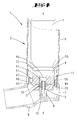
- the hand-held device 1 shown in a schematic sectional illustration in FIG. 3 serves for the portioned dispensing of sprayable substances, in particular of inhalation medicaments.
- the handset 1 first on a handset housing 2, in which a sprayable substance-containing cartridge 3 is used.
- This cartridge 3 is axially displaceable in the housing 2.
- the cartridge head 4 has a central, coaxial with the cartridge 3 extending valve tube 5. About the latter, a drug output is achieved by an axial relative movement between the cartridge 3 and housing 2.
- the housing 2 is divided into two and consists essentially of two superimposed ring members 6 and 7, of which the upper ring member 6 is formed like a shaft and the lower ring member 7 is an approximately transverse to the extension of the Schöffel aligned mouthpiece 8 has. The latter can be closed by a cap, not shown.
- valve tube 5 of the cartridge 3 is supported in an associated tubular support portion 9 within the lower ring member 7, this with axial mobility of the cartridge 3 within the surrounding the cartridge 3, shaft-like ring member. 6
- valve section 5 of the cartridge 3 clampingly receiving, formed within the lower housing ring member 7 support portion 9 is provided with a valve tube over a receiving portion receiving diameter flow channel 10 which communicates fluidly with the valve tube 5, wherein the valve tube 5 facing away End of the flow channel 10 in the direction of the mouthpiece 8 points.
- the two ring parts 6 and 7 are pluggable connected in the illustrated embodiment.
- the two parts can also be connected to one another via a thread, for example via a coarse thread with a high pitch.
- the arrangement of the cartridge 3 in the housing 2 is chosen so that the cartridge head 4 is placed in the housing 2 approximately at the height of the connecting portion between the ring member 6 and ring member 7.
- a stepping mechanism 11 is arranged in overlap with the cartridge valve tube 5. This is used to register and display the executed output actuation, this in dependence on the performed opening strokes of the cartridge.
- the stepper mechanism 11 is shown in Fig. 1 in a perspective exploded view.
- the central component of the stepping mechanism 11 is a planetary gear 12, consisting of a planetary gear 13, a sun gear 14, which sits on a underside toothed disc 15 and a cooperating with the planet gear 13 ring gear 16.
- the latter is the inside of a non-rotatably salaried, pipe section-shaped ring 17 formed.
- the jacket wall 18 of the ring 17 is penetrated in diametrically opposite areas of obliquely upward directed in the direction of switching outgoing slots 19, which open down to the ring gear 16 facing away from the ring edge open.
- the sprocket 16 extends in the axial direction approximately over half the height of the ring 17, whose shell wall 18 stepped to the ring gear 16 facing away from the annular end edge, is formed radially tapering.
- a latching finger 20 is integrally formed on the inside of the jacket wall 18 of the ring 17. This is offset with respect to a floor plan of the ring relative to the ring gear 16 radially inward; engages accordingly in a circular space drawn into the ring gear 16 radially inward.
- the arrangement of approximately elastically formed in the vertical direction locking finger 20 is chosen so that it engages approximately in a spanned by the lower marginal edges of the ring gear 16 horizontal plane.
- the diameter of the sun gear 14-carrying disc 15 is selected to be slightly smaller than the inner diameter of the ring 17 in the region of the ring gear 16.
- sun gear 14 and disc 15 are preferably integrally formed of the same material.
- a peripheral peripheral saw teeth 21 is provided, in which the latching finger 20 of the ring 17 engages.
- the sun gear 14 has a rough toothing.
- eight sun gear teeth 22 are formed evenly distributed. These teeth 22 cooperate in the course of the sun gear rotation with the arranged in the same plane between the sun gear 14 and the ring gear 16 of the ring 17 planetary gear 13.
- the planetary gear 13 has a one-sided upward, d. H. This is rotatably mounted in a bore 24 in the region of a disk-like radially inwardly facing collar 25 of a scale ring 26 of the disc 15 of the sun gear 14 projecting away.
- the scale ring 26 is mantelau touchwandig provided with a circumferential graduated scale 27, wherein the graduated scale corresponds to a plurality of individual rotary steps of the scale ring 26 continuing planetary gear 13.
- the indexing fingers 28 are arranged diametrically opposite to the main axis x of the entire stepper mechanism 11.
- a cylindrical central body in the form of a hub 29 is provided with a central axial through-hole 30.
- Their diameter is dimensioned slightly larger than the outer diameter of this through-hole 30 to be penetrated cartridge valve tube fifth
- the hub 29 merges into a radially enlarged collar 31.
- projecting guide portions 32 are formed, each forming in the region of their free ends in the associated slot 19 of the ring 17 guide pins 33.
- the indexing fingers 28 are each rooted with a horizontal portion on the guide portions 32 leaving the guide portion 33 projecting radially outward from the horizontal portion.
- the indexing fingers 28 projecting from the horizontal portions extend obliquely upward, such as at an angle of 45 degrees to the horizontal to the skewing of the slots 19 in the ring 17.
- the stepping finger star thus formed carries the reference S.
- the stepping finger star S, the inner ring gear 16 having ring 17, the integrally formed with the sun gear 14 disc 15 and the scale ring 26 are aligned concentrically with each other on the axis x, wherein the height of the ring 17 is selected so that both the Stepping finger star S and the sun gear 14 together with disc 15 are included in this.
- the entire planetary gear 12, as well as the stepping finger star S and the scale ring 26 are accommodated in a pot-like stepper housing 34 with an outer diameter, which is adapted to the outer diameter of the cartridge 3.
- the housing 34 has a jacket wall 35. This has a viewing window 36 through which the scale graduation 27 of the scale ring 26 can be seen.
- the housing cover 37 has a central opening 38 which, in the embodiment shown in FIG. 1, is surrounded by locking spring tongues tapering towards the housing interior in the embodiment 39 shown in FIG. 1.
- the aperture diameter is adapted to a diameter of a waist section 40 of a centrally projecting beyond the opening-side end wall of the cartridge 3 collar 41, from which latter the valve tube 5 grows.
- the housing can also be used independently of the cartridge 3.
- FIG. 4 shows a further embodiment.
- a blocking of the cartridge 3 in the region of the upper ring part housing 6 is provided.
- this upper housing ring part 6 projects obliquely downward retaining fingers 55, which are of uniform material, formed in one piece with the upper housing part 6.
- These retention fingers 55 are positioned so that their free marginal edges in the assignment position to the cartridge 3 enter into the formed behind the cartridge head 4 waist region of the cartridge 3 blocking, so as to block the cartridge 3.
- the retaining fingers 55 are formed such that they can be overrun by the cartridge head 4 at least during an initial loading of the housing 2 with the cartridge 3. Counting is not at this insertion.
- the provision of the actuated cartridge takes over the valve tube spring and that of the stepping mechanism, the spring force of the indexing finger 28th
- the housing bottom 42 is formed by a separate part. This is under inclusion of the above stepper gear items with the housing 34 connected, so for example. Welded with this or held by a press fit on this.
- the plate-like housing bottom 42 has a central bore for the passage of the valve tube 5. Furthermore, a locking piece 44 is formed on the housing bottom 42, which engages the position-oriented bondage of the ring 17 in a correspondingly formed in the jacket wall 18, window-like recess 45.
- the jacket outer wall of the housing bottom 42 has a cutout 46. In the installed state, this is assigned to the region of the outlet cross section of the flow channel 10 in the lower ring part housing 7.
- stepper mechanism 11 The operation of the stepper mechanism 11 is as follows:
- the switching elements (stepping finger star S, ring 17, disc 15, planet gear 13 and scale ring 26) as well as the housing 34 with the housing bottom 42 are arranged on axes which extend in the longitudinal direction of the cartridge 3.
- all other components of the stepper mechanism 11 are positioned on the cartridge longitudinal axis x - x.
- the stepping mechanism 11 is arranged corresponding concentric to the valve tube 5 in the shadow of the cartridge 3 within the housing 2, this concretely in the space between the cartridge head 4 and support portion 9 of the housing 2 space.
- the stepping mechanism 11 is supported on the end face of the support section 9 of the inhalation housing 2 with the hub 29 of the indexing finger star S mounted centrally in the rear derailleur housing 34.
- the central axis x of the cutting mechanism 11 is taken over by the body axis of the cartridge 3.
- the hub 29 passing through the valve tube 5 provides additional centering of the entire stepper unit.
- the entire stepper mechanism 11 by means of the housing 34 on the cartridge head protruding collar 41 can be fixed detent.
- the associated portions of the housing ring parts 6 and 7 also viewing window 47, 48, which are through the selected position, facing the mouthpiece 8 of the housing 2, in the field of view of the handset 1 serving user.
- this is provided with a projecting radially from the housing 34 guide leaf 49 which engages in a vertical groove, not shown in the interior of the housing 2, the displacement during lifting operation permitting.
- the latching between stepper mechanism 11 and cartridge 3 in the region of the cartridge head side collar 41 is selected such that when the cartridge 3 is removed from the housing 2, the stepper mechanism 11 on the cartridge 3 is pulled out with it.
Abstract
Description
Die Erfindung betrifft ein Handgerät zur portionierten Ausgabe sprühfähiger Substanzen, insbesondere Inhaliermedikamenten, gemäß Gattungsbegriff des Hauptanspruches.The invention relates to a hand-held device for portioned dispensing of sprayable substances, in particular inhalants, according to the preamble of the main claim.
Handgeräte der in Rede stehenden Art sind vorbekannt (
Aufgabe der Erfindung ist deshalb, ein Handgerät der in Rede stehenden Art in günstiger Weise bei vereinfachtem Aufbau so auszugestalten, dass man möglichst viele Schaltschritte auf dem Skalenring übersichtlich festhalten kann.The object of the invention is therefore to design a handset of the type in question in a favorable manner with a simplified structure so that you can hold as many switching steps on the scale ring clear.
Diese Problematik ist durch den Gegenstand des Anspruches 1 gelöst. Es ist ein Handgerät der in Rede stehenden Art geschaffen, welches bedingt durch die gewählte Konstruktion sowohl hinsichtlich des Platzbedarfes für das Schaltwerk als auch hinsichtlich der Reinigungsmöglichkeiten und darüber hinaus auch hinsichtlich der Handhabbarkeit in vorteilhafter Weise ausgebildet ist. Es ist ein mechanisch arbeitendes Schrittschaltwerk vorgesehen, welches aufgrund der gewählten Anordnung eine günstige, raumsparende Bauform aufweist. Man kommt mit einem Skalenring aus und selbst der braucht nicht mit kaum zu erkennbaren Strichunterteilungen versehen zu sein. Man kann z.B. zwischen zwei Skalenstrichen oder Zeichen immer eine bestimmte Anzahl von Entnahmebetätigungen vornehmen, ohne dass der Skalenring sich dreht. Man kann diese Handhabung auch in Abhängigkeit von bestimmten Medikamenten festlegen, z.B. wenn ein Medikament jeweils in drei Betätigungen eingegeben werden muss/soll. Die erste Eingabe ist auf der Skala dann erkennbar. Die zweite und dritte aber nicht als Drehung des Skalenringes verkörpert. Die Funktion ist nur durch rein mechanisch zusammenwirkende Bauteile gewährleistet. Dies trägt weiter zu einer vereinfachten Herstellbarkeit und kleiner Bauform bei. Die Lösung, dass das Planetenrad in einer Bohrung des Skalenrings lagert und das zugehörige Sonnenrad auf einer unterseitig gezahnten Scheibe sitzt, minimiert die Bauteile. Diese Scheibe steht in Eingriff mit dem Schaltfinger. Dieser greift in die Zahnung ein und ein Rastfinger sichert die jeweils erreichte Scheiben-Drehstellung. Sonnenrad und gezahnte Scheibe sind einteilig ausgeformt. Entsprechend sind auf dem Skalenring angepasst an das Kartuschenvolumen bspw. 200 oder 300 Hubstöße deutlich anzeigbar. Die auf der äußeren Mantelfläche des Skalenrings angeordnete und vor einem Sichtfenster des Gehäuses laufende Skaleneinteilung des Skalenrings entspricht jeweils mehreren Einzel-Drehschritten des Planetenrades. Diesbezüglich erweist es sich als vorteilhaft, dass hinsichtlich der Untersetzung ein Einzel-Drehschritt des Planetenrades erst nach Durchlauf mehrerer Einzel-Drehschritte des Sonnenrades erfolgt.This problem is solved by the subject matter of claim 1. It is created a hand-held device of the type in question, which due to the chosen design, both in terms of space requirements for the rear derailleur and in terms of cleaning options and beyond is also formed in terms of handling in an advantageous manner. There is provided a mechanically operating stepping mechanism, which has a favorable, space-saving design due to the selected arrangement. It comes with a scale ring and even that does not need to be provided with barely recognizable line divisions. For example, you can always make a certain number of picking operations between two scale lines or characters without the scale ring turning. You can also specify this handling depending on certain drugs, for example, if a drug must be entered in three operations / should be. The first entry is then recognizable on the scale. The second and third but not embodied as a rotation of the scale ring. The function is only guaranteed by purely mechanically interacting components. This further contributes to a simplified manufacturability and small size. The solution that the planet gear rests in a bore of the scale ring and the associated sun gear sits on a lower toothed disc minimizes the components. This disc is engaged with the shift finger. This engages in the toothing and a locking finger secures the respectively achieved disc rotation position. Sun gear and toothed disc are integrally formed. Accordingly, 200 or 300 strokes are clearly displayed on the scale ring adapted to the cartridge volume, for example. The arranged on the outer surface of the scale ring and running in front of a window of the housing scale graduation of the scale ring corresponds in each case to a plurality of individual rotation steps of the planet gear. In this regard, it proves to be advantageous that, with regard to the reduction, a single turning step of the planetary gear takes place only after passing through a plurality of individual turning steps of the sun gear.
Nachstehend ist der Gegenstand der Erfindung anhand der beigefügten Zeichnung, welche ein Ausführungsbeispiel darstellt, näher erläutert. Es zeigen:
- Fig. 1
- in perspektivischer Explosionsdarstellung das Schrittschaltwerk für das erfindungsgemäße Handgerät;
- Fig. 2
- einen Querschnitt durch das Schrittschaltwerk;
- Fig. 3
- in einer Längsschnittdarstellung das Handgerät in einer Ausführungsform, mit einem von einer Kartusche verrasteten, schematisch dargestellten Schrittschaltwerk,
- Fig. 4
- eine Bauform, bei welcher das Schrittschaltwerk nicht mit der Kartusche verrastet ist.
- Fig. 1
- in perspective exploded view of the stepping mechanism for the handset according to the invention;
- Fig. 2
- a cross section through the stepper mechanism;
- Fig. 3
- in a longitudinal sectional view of the hand-held device in one embodiment, with a latched by a cartridge, shown schematically stepper,
- Fig. 4
- a design in which the stepper is not locked to the cartridge.
Das in Fig. 3 in einer schematischen Schnittdarstellung gezeigte Handgerät 1 dient zur portionierten Ausgabe sprühfähiger Substanzen, insbesondere von Inhaliermedikamenten.The hand-held device 1 shown in a schematic sectional illustration in FIG. 3 serves for the portioned dispensing of sprayable substances, in particular of inhalation medicaments.
Hierzu weist das Handgerät 1 zunächst ein Handgerätgehäuse 2 auf, in welches eine die sprühfähige Substanz beinhaltende Kartusche 3 einsetzbar ist. Diese Kartusche 3 ist in dem Gehäuse 2 axial verschiebbar.For this purpose, the handset 1 first on a
In üblicher Weise weist der Kartuschenkopf 4 ein zentrales, sich koaxial zur Kartusche 3 erstreckendes Ventilrohr 5 auf. Über letzteres wird eine Medikamentenausgabe durch eine axiale Relativbewegung zwischen Kartusche 3 und Gehäuse 2 erreicht.In the usual way, the
Das Gehäuse 2 ist zweigeteilt und besteht im Wesentlichen aus zwei übereinander angeordneten Ringteilen 6 und 7, von welchen das obere Ringteil 6 schaftartig ausgeformt ist und das untere Ringteil 7 ein etwa quer zur Schafterstreckung ausgerichtetes Mundstück 8 aufweist. Letzteres ist durch eine nicht dargestellte Abdeckkappe verschließbar.The
Das Ventilrohr 5 der Kartusche 3 stützt sich in einem zugeordneten rohrförmigen Stützabschnitt 9 innerhalb des unteren Ringteiles 7 ab, dies bei axialer Beweglichkeit der Kartusche 3 innerhalb des die Kartusche 3 umgebenden, schaftartigen Ringteils 6.The
Der das Ventilrohr 5 der Kartusche 3 klemmend aufnehmende, innerhalb des unteren Gehäuse-Ringteils 7 ausgeformte Stützabschnitt 9 ist mit einem gegenüber einen das Ventilrohrende aufnehmenden Abschnitt durchmesserverringerten Strömungskanal 10 versehen, welcher strömungstechnisch in Verbindung steht mit dem Ventilrohr 5, wobei das dem Ventilrohr 5 abgewandte Ende des Strömungskanals 10 in Richtung auf das Mundstück 8 weist.The
Die beiden Ringteile 6 und 7 sind in dem dargestellten Ausführungsbeispiel steckbar miteinander verbunden. Alternativ können die beiden Teile auch über ein Gewinde, bspw. über ein Grobgewinde mit hoher Steigung, miteinander verbunden sein.The two
Die Anordnung der Kartusche 3 in dem Gehäuse 2 ist so gewählt, dass der Kartuschenkopf 4 in dem Gehäuse 2 etwa auf Höhe des Verbindungsbereiches zwischen Ringteil 6 und Ringteil 7 platziert ist.The arrangement of the
Zentral unterhalb der öffnungsseitigen Stirnwand der Kartusche 3 ist in Überlappung zum Kartuschen-Ventilrohr 5 ein Schrittschaltwerk 11 angeordnet. Dieses dient zum Registrieren und Anzeigen der durchgeführten Ausgabebetätigungen, dies in Abhängigkeit von den durchgeführten Öffnungshüben der Kartusche 3.Centrally below the opening-side end wall of the
Das Schrittschaltwerk 11 ist in Fig. 1 in einer perspektivischen Explosionsdarstellung gezeigt. Zentraler Bestandteil des Schrittschaltwerks 11 ist ein Planetenrad-Getriebe 12, bestehend aus einem Planetenrad 13, einem Sonnenrad 14, welches auf einer unterseitig gezahnten Scheibe 15 sitzt und einem mit dem Planetenrad 13 zusammenwirkenden Zahnkranz 16. Letzterer ist wandungsinnenseitig eines nicht drehbar gehalterten, rohrabschnittförmigen Ringes 17 ausgeformt. Die Mantelwandung 18 des Ringes 17 ist in diametral gegenüberliegenden Bereichen durchsetzt von schräg aufwärts in Schaltrichtung gerichtet ausgehenden Schlitzen 19, die nach unten zur dem Zahnkranz 16 abgewandten Ringkante hin offen auslaufen.The
Der Zahnkranz 16 erstreckt sich in axialer Richtung etwa über die halbe Höhe des Ringes 17, dessen Mantelwandung 18 zur dem Zahnkranz 16 abgewandten Ringstirnkante hin abgestuft, sich radial verjüngend ausgebildet ist.The
Unterhalb des Zahnkranzes 16 ist innenseitig der Mantelwandung 18 des Ringes 17 ein Rastfinger 20 angeformt. Dieser ist mit Bezug auf einen Grundriss des Ringes gegenüber dem Zahnkranz 16 nach radial innen versetzt; greift entsprechend in einen zum Zahnkranz 16 nach radial innen eingezogenen Kreisraum. Weiter ist die Anordnung des in etwa in Vertikalrichtung elastisch ausgebildeten Rastfingers 20 so gewählt, dass dieser etwa in eine durch die unteren Randkanten des Zahnkranzes 16 aufgespannte Horizontalebene eingreift.Below the
Der Durchmesser der das Sonnenrad 14 tragenden Scheibe 15 ist geringfügig kleiner gewählt, als der Innendurchmesser des Ringes 17 im Bereich des Zahnkranzes 16. Sonnenrad 14 und Scheibe 15 sind bevorzugt einstückig, materialeinheitlich ausgebildet.The diameter of the sun gear 14-carrying
Unterseitig der Scheibe 15 ist eine randbezogen umlaufende Sägezahnung 21 vorgesehen, in welche der Rastfinger 20 des Ringes 17 eingreift.On the underside of the
Das Sonnenrad 14 weist eine grobe Verzahnung auf. So sind in dem dargestellten Ausführungsbeispiel über den Umfang des Sonnenrades 14 acht Sonnenrad-Zähne 22 gleichmäßig verteilt ausgeformt. Diese Zähne 22 wirken im Zuge der Sonnenrad-Umdrehung mit dem in derselben Ebene zwischen dem Sonnenrad 14 und dem Zahnkranz 16 des Ringes 17 angeordneten Planetenrad 13 zusammen.The
Das Planetenrad 13 besitzt einen einseitig nach oben, d. h. von der Scheibe 15 des Sonnenrades 14 weg abragenden Achszapfen 23. Dieser ist in einer Bohrung 24 im Bereich eines scheibenartig nach radial innen weisenden Kragens 25 eines Skalenringes 26 drehbar gefasst. Der Skalenring 26 ist mantelaußenwandig mit einer umlaufenden Skaleneinteilung 27 versehen, wobei die Skaleneinteilung jeweils mehreren Einzel-Drehschritten des den Skalenring 26 weiterführenden Planetenrades 13 entspricht.The
Die schrittweise Verlagerung des Sonnenrades 14 bzw. der einstückig hiermit ausgeformten Scheibe 15 erfolgt über etwa vertikal federnd ausweichbar ausgebildete Schrittschaltfinger 28. Diese greifen unterseitig in die Sägezahnung 21 der Scheibe 15.The stepwise displacement of the
Die Schrittschaltfinger 28 sind mit Bezug zu der Hauptachse x des gesamten Schrittschaltwerkes 11 diametral gegenüberliegend angeordnet. Hierzu ist zunächst ein zylinderförmiger Zentralkörper in Form einer Nabe 29 vorgesehen mit einer zentralen axialen Durchgangsbohrung 30. Deren Durchmesser ist geringfügig größer bemessen als der Außendurchmesser des diese Durchgangsbohrung 30 zu durchsetzenden Kartuschen-Ventilrohres 5.The
Fußseitig geht die Nabe 29 über in einen radial erweiterten Kragen 31. An diesem sind diametral gegenüberliegend in Radialrichtung abragende Führungsabschnitte 32 angeformt, die jeweils im Bereich ihrer freien Enden einen in dem zugeordneten Schlitz 19 des Ringes 17 einliegenden Führungszapfen 33 ausformen.On the foot side, the
Die Schrittschaltfinger 28 wurzeln jeweils mit einem Horizontalabschnitt an den Führungsabschnitten 32 unter Belassen der über den horizontalen Abschnitt radial außen abragenden Führungszapfen 33. Die von den Horizontalabschnitten abragenden Schrittschaltfinger 28 gehen schräg aufwärts gerichtet aus, etwa unter Einschließen eines Winkels von 45 Grad zur Horizontalen, angepasst an die Schrägung der Schlitze 19 im Ring 17. Der so gebildete Schrittschaltfinger-Stern trägt das Bezugszeichen S.The
Der Schrittschaltfinger-Stern S, der den inneren Zahnkranz 16 aufweisende Ring 17, die einstückig mit dem Sonnenrad 14 ausgeformte Scheibe 15 sowie der Skalenring 26 sind konzentrisch zueinander auf der Achse x ausgerichtet, wobei die Höhe des Ringes 17 so gewählt ist, dass sowohl der Schrittschaltfinger-Stern S als auch das Sonnenrad 14 samt Scheibe 15 in diesem aufgenommen sind.The stepping finger star S, the
Das gesamte Planeten-Getriebe 12, sowie der Schrittschaltfinger-Stern S und der Skalenring 26 sind aufgenommen in einem topfartigen Schrittschaltwerkgehäuse 34 mit einem Außendurchmesser, welcher an den Außendurchmesser der Kartusche 3 angepasst ist.The entire
Das Gehäuse 34 besitzt eine Mantelwandung 35. Diese weist ein Sichtfenster 36 auf, durch welches die Skaleneinteilung 27 des Skalenrings 26 erkennbar ist.The
Die Gehäusedecke 37 besitzt eine zentrale Durchbrechung 38, welche in der in den Figur 1 gezeigten Ausführungsform umfasst ist von konisch zum Gehäuseinnern hin zulaufenden Rast-Federzungen in der in de Figur 1 gezeigten Ausführungsform 39. Der Durchbrechungs-Durchmesser ist angepasst an einen Durchmesser eines Taillenabschnittes 40 eines über die öffnungsseitige Stirnwand der Kartusche 3 zentral überragenden Kragens 41, aus welch letzterem das Ventilrohr 5 auswächst. Wie in Figur 4 dargestellt, kann das Gehäuse aber auch unabhängig von der Kartusche 3 eingesetzt sein.The
Die Darstellung in Figur 4 zeigt eine weitere Ausführungsform. Dort ist zur weiteren Festlegung der Kartusche 3 - neben einer üblichen Klemmhalterung des Ventilrohrs 5 in dem handgerätgehäuseseitigen Stützabschnitt 9 - eine Blockierung der Kartusche 3 im Bereich des oberen Ringteil-Gehäuses 6 vorgesehen. So ragen mantelinnenseitig dieses oberen Gehäuseringteiles 6 schräg abwärts gerichtete Rückhaltefinger 55 ab, welche materialeinheitlich, einstückig mit dem oberen Gehäuseteil 6 gebildet sind. Diese Rückhaltefinger 55 sind so positioniert, dass deren freien Randkanten in der Zuordnungsstellung zur Kartusche 3 in den hinter dem Kartuschenkopf 4 ausgeformten Taillenbereich der Kartusche 3 sperrend eintreten, um so die Kartusche 3 zu blockieren. Weiter sind die Rückhaltefinger 55 derart ausgeformt, dass diese zumindest bei einer Erstbestückung des Gehäuses 2 mit der Kartusche 3 durch den Kartuschenkopf 4 überlaufen werden können. Gezählt wird bei diesem Einsetzen nicht. Die Rückstellung der betätigten Kartusche übernimmt deren Ventilrohr-Feder und diejenige des Schrittschaltwerkes die Federkraft der Schrittschaltfinger 28.The illustration in FIG. 4 shows a further embodiment. There is for further determination of the cartridge 3 - in addition to a conventional clamp of the
Der Gehäuseboden 42 ist gebildet durch ein gesondertes Teil. Dieses ist unter Aufnahme der vorbeschriebenen Schrittschaltwerk-Einzelteile mit dem Gehäuse 34 verbunden, so bspw. mit diesem verschweißt oder über eine Presspassung an diesem gehaltert.The
Der tellerartige Gehäuseboden 42 besitzt eine zentrale Bohrung zum Durchtritt des Ventilrohres 5. Des Weiteren ist auf dem Gehäuseboden 42 ein Raststück 44 ausgeformt, welches zur lageorientierten Fesselung des Ringes 17 in eine entsprechend in dessen Mantelwandung 18 ausgeformte, fensterartige Ausnehmung 45 greift.The plate-like housing bottom 42 has a central bore for the passage of the
Im selben Winkelbereich, in welchem das Passstück 44 auf dem Boden angeordnet ist, weist die Mantelaußenwandung des Gehäusebodens 42 einen Freischnitt 46 auf. Diese ist im Einbauzustand dem Bereich des Ausgangsquerschnittes des Strömungskanals 10 im unteren Ringteilgehäuse 7 zugeordnet.In the same angular range in which the
Die Schaltglieder (Schrittschaltfinger-Stern S, Ring 17, Scheibe 15, Planetenrad 13 und Skalenring 26) wie auch das Gehäuse 34 mit dem Gehäuseboden 42 sind auf Achsen angeordnet, die sich in Längsrichtung der Kartusche 3 erstrecken. So sind mit Ausnahme des Planetenrades 13 alle weiteren Bauteile des Schrittschaltwerkes 11 auf der Kartuschenlängsachse x - x positioniert.The switching elements (stepping finger star S,
Das Schrittschaltwerk 11 ist entsprechend konzentrisch zum Ventilrohr 5 im Schatten der Kartusche 3 innerhalb des Gehäuses 2 angeordnet, dies konkret in dem zwischen Kartuschenkopf 4 und Stützabschnitt 9 des Gehäuses 2 belassenen Bauraum. Das Schrittschaltwerk 11 stützt sich mit der in dem Schaltwerkgehäuse 34 zentral gelagerten Nabe 29 des Schrittschaltfinger-Sterns S auf der Stirnfläche des Stützabschnitts 9 des Inhaliergehäuses 2 ab. Die zentrale Achse x des Schnittschaltwerks 11 wird von der Körperachse der Kartusche 3 übernommen. Das die Nabe 29 durchsetzende Ventilrohr 5 bietet eine zusätzliche Zentrierung der gesamten Schrittschaltwerk-Einheit.The
Bei Durchführung eines Betätigungshubs der Kartusche 3 und damit einhergehender Vertikalverlagerung derselben in Richtung auf den Stützabschnitt 9 wird das Schaltwerkgehäuse 34 über den Kartuschenkopf 4 mitgeschleppt, dies unter Relativverlagerung des Gehäuses 34, des Planetenrad-Getriebes 12 und des Skalenringes 26 zu dem Schrittschaltfinger-Stern S, welcher eine Abstützung auf dem Stützabschnitt 9 erfährt. Infolgedessen bewirken die sich spannenden Schrittschaltfinger 28 durch Drehaufgleiten des Schrittschaltfinger-Sterns S in den mantelwandseitigen Schlitzen 19 des Ringes 17 einen schrittweisen Drehvorschub der sägeverzahnten Scheibe 15. Einhergehend damit dreht sich das Sonnenrad 14 um denselben Winkelbetrag. Die Schrittschaltfinger 28 bewegen sich hierbei aus der schrägen Ausrichtung in Richtung auf eine senkrecht zur Längsachse x - x ausgerichtete Ebene.When performing a Betätigungshubs the
Dadurch bedingt, dass das Sonnenrad 14 lediglich acht gleichmäßig über den Umfang verteilt angeordnete Zähne aufweist, führt nicht jede Schritt-Drehbewegung des Sonnenrades 14 zwangsläufig zu einer Drehbewegung des Planetenrades 13. Vielmehr wird die Drehung des Planetenrades 13 um dessen Achse und eine die damit einhergehende Drehverlagerung des Skalenringes 26 erst nach mehreren Einzel-Drehschritten des Sonnenrades 14 durchgeführt.Due to the fact that the
Gemäß der Darstellung in Fig. 3 ist das gesamte Schrittschaltwerk 11 mittels des Gehäuses 34 an dem kartuschenkopfseitig vorragenden Kragen 41 rastend festlegbar. Zugeordnet zu dem gehäuseseitigen Sichtfenster 36 weisen die zugeordneten Abschnitte der Gehäuseringteile 6 und 7 gleichfalls Sichtfenster 47, 48 auf, welche durch die gewählte Position, zugewandt dem Mundstück 8 des Gehäuses 2, im Blickfeld des das Handgerät 1 bedienenden Benutzers liegen. Zur lageorientierten Einführung des Schrittschaltwerkes 11 ist dieses mit einem radial von dem Gehäuse 34 abragenden Führungsblatt 49 versehen, welches in eine nicht näher dargestellte Vertikalnut im Innern des Gehäuses 2, den Verschiebeweg bei Hubbetätigung zulassend eingreift.As shown in Fig. 3, the
Die Verrastung zwischen Schrittschaltwerk 11 und Kartusche 3 im Bereich des kartuschenkopfseitigen Kragens 41 ist so gewählt, dass bei einer Entnahme der Kartusche 3 aus dem Gehäuse 2 das Schrittschaltwerk 11 an der Kartusche 3 verbleibend mit ausgezogen wird.The latching between
Claims (2)
dadurch gekennzeichnet, dass ein Planetenrad (13) eines Planetengetriebes (12) in einer Bohrung (24) des Skalenringes (26) lagert und das zugehörige Sonnenrad (14) auf der Oberseite einer unterseitig gezahnten Scheibe (15) ausgebildet ist derart, dass es den Drehwinkel untersetzt über das Planetenrad (13) an den Skalenring (26) weitergibt derart, dass erst nach Durchlauf mehrerer Einzel-Drehschritte des Sonnenrades (14) ein Drehschritt des Planetenrades (13) erfolgt.Hand-held device (1) for the portioned dispensing of sprayable substances, in particular inhalants, with a cartridge (3) which can be displaced into the dispensing position by pressing on a housing and a switching mechanism (11) which moves along with the opening stroke of the cartridge (3) for registration and display performed output operations, which derailleur (11) has a concentric with the valve tube (5) encircling scale ring (26) which is rotated via a gear transmission (12) by a sprocket (16) stepwise,
characterized in that a planetary gear (13) of a planetary gear (12) in a bore (24) of the scale ring (26) superimposed and the associated sun gear (14) on the upper side of a bottom toothed disc (15) is formed such that it Squared over the planet gear (13) to the scale ring (26) weiterergibt such that only after passing through a plurality of individual rotational steps of the sun gear (14), a rotation step of the planet gear (13).
Applications Claiming Priority (3)
| Application Number | Priority Date | Filing Date | Title |
|---|---|---|---|
| DE102004054179 | 2004-11-10 | ||
| DE102005033398A DE102005033398A1 (en) | 2004-11-10 | 2005-07-18 | Inhale device |
| EP05792078.7A EP1828967B1 (en) | 2004-11-10 | 2005-08-23 | Inhaler |
Related Parent Applications (2)
| Application Number | Title | Priority Date | Filing Date |
|---|---|---|---|
| EP05792078.7A Division EP1828967B1 (en) | 2004-11-10 | 2005-08-23 | Inhaler |
| EP05792078.7A Division-Into EP1828967B1 (en) | 2004-11-10 | 2005-08-23 | Inhaler |
Publications (3)
| Publication Number | Publication Date |
|---|---|
| EP1868141A2 true EP1868141A2 (en) | 2007-12-19 |
| EP1868141A3 EP1868141A3 (en) | 2010-01-13 |
| EP1868141B1 EP1868141B1 (en) | 2016-11-09 |
Family
ID=35407047
Family Applications (4)
| Application Number | Title | Priority Date | Filing Date |
|---|---|---|---|
| EP05792078.7A Active EP1828967B1 (en) | 2004-11-10 | 2005-08-23 | Inhaler |
| EP08159421.0A Active EP1970842B1 (en) | 2004-11-10 | 2005-08-23 | Inhaler |
| EP07116846.2A Active EP1868141B1 (en) | 2004-11-10 | 2005-08-23 | Inhaler |
| EP05803452.1A Active EP1810228B1 (en) | 2004-11-10 | 2005-11-08 | Step-by-step mechanism |
Family Applications Before (2)
| Application Number | Title | Priority Date | Filing Date |
|---|---|---|---|
| EP05792078.7A Active EP1828967B1 (en) | 2004-11-10 | 2005-08-23 | Inhaler |
| EP08159421.0A Active EP1970842B1 (en) | 2004-11-10 | 2005-08-23 | Inhaler |
Family Applications After (1)
| Application Number | Title | Priority Date | Filing Date |
|---|---|---|---|
| EP05803452.1A Active EP1810228B1 (en) | 2004-11-10 | 2005-11-08 | Step-by-step mechanism |
Country Status (11)
| Country | Link |
|---|---|
| US (3) | US7827984B2 (en) |
| EP (4) | EP1828967B1 (en) |
| BR (2) | BRPI0517303A (en) |
| CA (2) | CA2587612C (en) |
| DE (1) | DE102005033398A1 (en) |
| DK (3) | DK1828967T3 (en) |
| ES (4) | ES2605553T3 (en) |
| HU (3) | HUE032848T2 (en) |
| MX (2) | MX2007005586A (en) |
| PL (4) | PL1970842T3 (en) |
| WO (2) | WO2006051006A1 (en) |
Families Citing this family (60)
| Publication number | Priority date | Publication date | Assignee | Title |
|---|---|---|---|---|
| US9006175B2 (en) | 1999-06-29 | 2015-04-14 | Mannkind Corporation | Potentiation of glucose elimination |
| EP2280004B1 (en) | 1999-06-29 | 2016-04-20 | MannKind Corporation | Pharmaceutical formulations comprising insulin complexed with a diketopiperazine |
| WO2003080149A2 (en) | 2002-03-20 | 2003-10-02 | Mannkind Corporation | Inhalation apparatus |
| FR2857770B1 (en) * | 2003-07-18 | 2005-10-21 | Valois Sas | IMPROVED DOSAGE INDICATOR FOR FLUID PRODUCT DISPENSING DEVICE. |
| FR2857769B1 (en) * | 2003-07-18 | 2005-10-21 | Valois Sa | IMPROVED DOSAGE INDICATOR FOR FLUID PRODUCT DISPENSING DEVICE. |
| FR2858867B1 (en) * | 2003-08-12 | 2005-11-04 | Valois Sa | DOSING INDICATOR FOR FLUID PRODUCT DISPENSING DEVICE |
| GB2414187B (en) * | 2004-05-21 | 2007-03-07 | Bespak Plc | Dispensing apparatus |
| JP5078014B2 (en) | 2004-08-20 | 2012-11-21 | マンカインド コーポレイション | Catalytic reaction of diketopiperazine synthesis. |
| MX2007002189A (en) | 2004-08-23 | 2008-01-11 | Mannkind Corp | Diketopiperazine salts, diketomorpholine salts or diketodioxane salts for drug delivery. |
| DE102005033398A1 (en) * | 2004-11-10 | 2006-05-11 | Alfred Von Schuckmann | Inhale device |
| GB0425518D0 (en) | 2004-11-19 | 2004-12-22 | Clinical Designs Ltd | Substance source |
| GB0428204D0 (en) | 2004-12-23 | 2005-01-26 | Clinical Designs Ltd | Medicament container |
| GB0518400D0 (en) | 2005-09-09 | 2005-10-19 | Clinical Designs Ltd | Dispenser |
| US7803404B2 (en) | 2005-09-14 | 2010-09-28 | Mannkind Corporation | Method of drug formulation based on increasing the affinity of active agents for crystalline microparticle surfaces |
| WO2007045904A1 (en) * | 2005-10-22 | 2007-04-26 | 42 Technology Limited | Dose counter for inhalation devices |
| IN2015DN00888A (en) | 2006-02-22 | 2015-07-10 | Mannkind Corp | |
| GB2438396B (en) | 2006-05-26 | 2008-10-01 | Bespak Plc | Improvements in or relating to dispensing apparatus |
| GB0610541D0 (en) | 2006-05-26 | 2006-07-05 | Bespak Plc | Improvements in or relating to dispensing apparatus |
| RU2009105638A (en) * | 2006-08-22 | 2010-09-27 | Глакса Груп Лимитед (GB) | ACTUATOR FOR INHALER |
| DE102007045438B4 (en) * | 2007-09-22 | 2016-09-01 | Boehringer Ingelheim International Gmbh | Inhale device |
| RU2467741C2 (en) * | 2007-10-24 | 2012-11-27 | Маннкайнд Корпорейшн | Active substance delivery |
| KR101933816B1 (en) | 2008-06-13 | 2019-03-29 | 맨카인드 코포레이션 | A dry powder inhaler and system for drug delivery |
| US8485180B2 (en) | 2008-06-13 | 2013-07-16 | Mannkind Corporation | Dry powder drug delivery system |
| WO2009155581A1 (en) | 2008-06-20 | 2009-12-23 | Mannkind Corporation | An interactive apparatus and method for real-time profiling of inhalation efforts |
| DE102008030443A1 (en) | 2008-06-26 | 2009-12-31 | Rpc Formatec Gmbh | Step-by-step system for a hand-held device for releasing a medicine to be inhaled in portions comprises a planetary wheel which rotates in single rotary steps using springs |
| TWI494123B (en) | 2008-08-11 | 2015-08-01 | Mannkind Corp | Use of ultrarapid acting insulin |
| DE102008044770A1 (en) * | 2008-08-28 | 2010-03-25 | Boehringer Ingelheim Pharma Gmbh & Co. Kg | Drive unit for dose counter |
| US8314106B2 (en) | 2008-12-29 | 2012-11-20 | Mannkind Corporation | Substituted diketopiperazine analogs for use as drug delivery agents |
| GB0904040D0 (en) | 2009-03-10 | 2009-04-22 | Euro Celtique Sa | Counter |
| GB0904059D0 (en) | 2009-03-10 | 2009-04-22 | Euro Celtique Sa | Counter |
| PL2405963T3 (en) | 2009-03-11 | 2014-04-30 | Mannkind Corp | Apparatus, system and method for measuring resistance of an inhaler |
| BRPI1013154B1 (en) | 2009-06-12 | 2020-04-07 | Mannkind Corp | MICROPARTICLES OF DICETOPIPERAZINE WITH SPECIFIC SURFACE AREAS DEFINED, DRY POWDER UNDERSTANDING THE REFERRED MICROPARTICLES, METHOD FOR FORMATION OF THE REFERENCESMICROPARTICLES AND THE FORMATION OF MICROPARTYSTEMS |
| CA2778698A1 (en) | 2009-11-03 | 2011-05-12 | Mannkind Corporation | An apparatus and method for simulating inhalation efforts |
| US10857311B2 (en) | 2010-01-12 | 2020-12-08 | Omega Life Science Ltd. | Method and apparatus for producing fine concentrated aerosol |
| MX359281B (en) | 2010-06-21 | 2018-09-21 | Mannkind Corp | Dry powder drug delivery system and methods. |
| MX353285B (en) | 2011-04-01 | 2018-01-05 | Mannkind Corp | Blister package for pharmaceutical cartridges. |
| GB2491611B (en) * | 2011-06-08 | 2014-01-01 | Consort Medical Plc | Dose indicator device |
| WO2012174472A1 (en) | 2011-06-17 | 2012-12-20 | Mannkind Corporation | High capacity diketopiperazine microparticles |
| US9202164B2 (en) | 2011-09-26 | 2015-12-01 | Trudell Medical International | Dose counter and medication delivery device |
| IN2014DN03093A (en) | 2011-10-24 | 2015-05-15 | Mannkind Corp | |
| EP2782713B1 (en) * | 2011-11-04 | 2020-01-08 | Kyocera Senco Industrial Tools, Inc. | Screwdriver tool with improved corner fit function |
| WO2013127738A1 (en) * | 2012-02-28 | 2013-09-06 | Boehringer Ingelheim International Gmbh | Novel propellant-gas-containing tiotropium formulation |
| SG10201605800UA (en) | 2012-07-12 | 2016-09-29 | Mannkind Corp | Dry powder drug delivery system and methods |
| US9089444B2 (en) | 2012-08-30 | 2015-07-28 | Adam Soss | Valve for prosthesis attachment |
| WO2014066856A1 (en) | 2012-10-26 | 2014-05-01 | Mannkind Corporation | Inhalable influenza vaccine compositions and methods |
| KR102499439B1 (en) | 2013-03-15 | 2023-02-13 | 맨카인드 코포레이션 | Microcrystalline diketopiperazine compositions and methods |
| CA2918369C (en) | 2013-07-18 | 2021-06-29 | Mannkind Corporation | Heat-stable dry powder pharmaceutical compositions and methods |
| WO2015021064A1 (en) | 2013-08-05 | 2015-02-12 | Mannkind Corporation | Insufflation apparatus and methods |
| DE102014114462A1 (en) | 2013-10-15 | 2015-04-16 | Alfred Von Schuckmann | Counter and handset with counter |
| US10307464B2 (en) | 2014-03-28 | 2019-06-04 | Mannkind Corporation | Use of ultrarapid acting insulin |
| JP6745225B2 (en) * | 2014-05-07 | 2020-08-26 | ベーリンガー インゲルハイム インターナショナル ゲゼルシャフト ミット ベシュレンクテル ハフツング | Container, display device, and nebulizer |
| ES2874029T3 (en) * | 2014-05-07 | 2021-11-04 | Boehringer Ingelheim Int | Nebulizer |
| EP3149661A1 (en) * | 2014-05-28 | 2017-04-05 | Sanofi SA | Assembly for a counter mechanism for a drug delivery device and drug delivery device |
| US10561806B2 (en) | 2014-10-02 | 2020-02-18 | Mannkind Corporation | Mouthpiece cover for an inhaler |
| IL292671B2 (en) | 2014-10-13 | 2023-05-01 | Omega Life Science Ltd | Nebulizers |
| DE102014118325A1 (en) | 2014-12-10 | 2016-06-16 | Alfred Von Schuckmann | counter |
| DE102015120948A1 (en) | 2015-12-02 | 2017-06-08 | Alfred Von Schuckmann | Hand-held device for dispensing a pharmaceutical substance and counter and screw cap for such a hand-held device |
| DE102016106875A1 (en) | 2016-04-13 | 2017-10-19 | Alfred Von Schuckmann | Hand-held device for dispensing a pharmaceutical substance and counter for such a hand-held device |
| USD901671S1 (en) | 2018-11-28 | 2020-11-10 | Rpc Formatec Gmbh | Inhaler |
| US11273541B2 (en) | 2019-03-18 | 2022-03-15 | Kyocera Senco Industrial Tools, Inc. | Autofeed screwdriver attachment with twist collar to activate movable plates for latching to screw gun |
Citations (6)
| Publication number | Priority date | Publication date | Assignee | Title |
|---|---|---|---|---|
| US3107855A (en) * | 1960-04-27 | 1963-10-22 | Floyd E Miner | Odometer mechanism |
| EP1065477A2 (en) * | 1999-06-30 | 2001-01-03 | Microspray Delta S.p.A. | Liquid dose dispenser with device for counting a large number of dispensed doses |
| US6431168B1 (en) * | 1997-06-10 | 2002-08-13 | Smithkline Beecham Corporation | Dispenser with doses′ counter |
| US20040144798A1 (en) * | 2001-02-23 | 2004-07-29 | Tianhong Ouyang | Dosage counting devices |
| US20040149772A1 (en) * | 2001-02-23 | 2004-08-05 | Tianhong Ouyang | Dosage counting devices |
| US20040211420A1 (en) * | 2002-09-21 | 2004-10-28 | Aventis Pharma Limited | Inhaler |
Family Cites Families (18)
| Publication number | Priority date | Publication date | Assignee | Title |
|---|---|---|---|---|
| GB1317315A (en) * | 1970-12-17 | 1973-05-16 | English Numbering Machines | Mechanical impulse counter |
| DE59107710D1 (en) * | 1990-08-31 | 1996-05-30 | Pfeiffer Erich Gmbh & Co Kg | Discharge device for media |
| IT1243820B (en) * | 1990-10-09 | 1994-06-28 | Elettro Plastica Spa | CONTADOSI DEVICE FOR DISPENSING DOSES OF FLUID PRODUCT, PARTICULARLY FOR PHARMACEUTICAL USE |
| FR2721106B1 (en) * | 1994-06-10 | 1996-09-13 | Step | Dose counter for inhalers. |
| SE9404140D0 (en) * | 1994-11-29 | 1994-11-29 | Astra Ab | Dose indicating device |
| ES2137013T3 (en) * | 1995-07-29 | 1999-12-01 | Rocep Lusol Holdings | APPARATUS FOR MIXING A FLUID AND A LIQUID. |
| GB2320489A (en) * | 1996-12-20 | 1998-06-24 | Norton Healthcare Ltd | Inhaler dose counter |
| GB9807558D0 (en) * | 1998-04-09 | 1998-06-10 | Bason Neil P | An indicator device |
| US6083228A (en) * | 1998-06-09 | 2000-07-04 | Michelson; Gary K. | Device and method for preparing a space between adjacent vertebrae to receive an insert |
| DE29814647U1 (en) * | 1998-08-14 | 1999-12-23 | Wischerath Josef Gmbh Co Kg | Inhaler with a metering device |
| ES2213614T3 (en) * | 1999-10-16 | 2004-09-01 | Glaxo Group Limited | ACCOMMODATION DEVICE FOR AEROSOL PACKAGING. |
| GB2372542B (en) * | 2001-02-23 | 2003-08-20 | Bespak Plc | Dosage counting devices |
| US7004164B2 (en) * | 2002-03-21 | 2006-02-28 | Trudell Medical International | Indicating device for aerosol container |
| EP1369139A1 (en) * | 2002-06-03 | 2003-12-10 | 3M Innovative Properties Company | Dose indicators and dispensing canister-indicator assemblies |
| DE50214739D1 (en) * | 2002-06-12 | 2010-12-09 | Boehringer Ingelheim Int | NUMBER OF PAYMENTS FOR DOSED DISPENSES OF LIQUID, PASTIC OR SOLID PRODUCTS AND DEVICE FOR DISPOSING SUCH PRODUCTS |
| GB2398503A (en) * | 2003-02-11 | 2004-08-25 | Bespak Plc | Inhaler with removable mouthpiece |
| FR2858867B1 (en) * | 2003-08-12 | 2005-11-04 | Valois Sa | DOSING INDICATOR FOR FLUID PRODUCT DISPENSING DEVICE |
| DE102005033398A1 (en) * | 2004-11-10 | 2006-05-11 | Alfred Von Schuckmann | Inhale device |
-
2005
- 2005-07-18 DE DE102005033398A patent/DE102005033398A1/en not_active Ceased
- 2005-08-23 EP EP05792078.7A patent/EP1828967B1/en active Active
- 2005-08-23 PL PL08159421T patent/PL1970842T3/en unknown
- 2005-08-23 EP EP08159421.0A patent/EP1970842B1/en active Active
- 2005-08-23 EP EP07116846.2A patent/EP1868141B1/en active Active
- 2005-08-23 ES ES07116846.2T patent/ES2605553T3/en active Active
- 2005-08-23 CA CA2587612A patent/CA2587612C/en active Active
- 2005-08-23 PL PL05792078T patent/PL1828967T3/en unknown
- 2005-08-23 HU HUE05792078A patent/HUE032848T2/en unknown
- 2005-08-23 WO PCT/EP2005/054138 patent/WO2006051006A1/en active Application Filing
- 2005-08-23 BR BRPI0517303-5A patent/BRPI0517303A/en not_active IP Right Cessation
- 2005-08-23 ES ES08159421T patent/ES2761650T3/en active Active
- 2005-08-23 DK DK05792078.7T patent/DK1828967T3/en active
- 2005-08-23 MX MX2007005586A patent/MX2007005586A/en active IP Right Grant
- 2005-08-23 HU HUE07116846A patent/HUE032742T2/en unknown
- 2005-08-23 DK DK07116846.2T patent/DK1868141T3/en active
- 2005-08-23 HU HUE08159421A patent/HUE047138T2/en unknown
- 2005-08-23 ES ES05792078.7T patent/ES2611758T3/en active Active
- 2005-08-23 PL PL07116846T patent/PL1868141T3/en unknown
- 2005-11-08 EP EP05803452.1A patent/EP1810228B1/en active Active
- 2005-11-08 WO PCT/EP2005/055823 patent/WO2006051073A1/en active Application Filing
- 2005-11-08 MX MX2007005589A patent/MX2007005589A/en active IP Right Grant
- 2005-11-08 BR BRPI0517696-4A patent/BRPI0517696A/en active IP Right Grant
- 2005-11-08 PL PL05803452.1T patent/PL1810228T3/en unknown
- 2005-11-08 ES ES05803452.1T patent/ES2592303T3/en active Active
- 2005-11-08 DK DK05803452.1T patent/DK1810228T3/en active
- 2005-11-08 CA CA2587615A patent/CA2587615C/en active Active
-
2007
- 2007-05-10 US US11/747,051 patent/US7827984B2/en active Active
- 2007-05-10 US US11/747,013 patent/US7448342B2/en active Active
-
2008
- 2008-10-20 US US12/254,106 patent/US7984710B2/en active Active
Patent Citations (6)
| Publication number | Priority date | Publication date | Assignee | Title |
|---|---|---|---|---|
| US3107855A (en) * | 1960-04-27 | 1963-10-22 | Floyd E Miner | Odometer mechanism |
| US6431168B1 (en) * | 1997-06-10 | 2002-08-13 | Smithkline Beecham Corporation | Dispenser with doses′ counter |
| EP1065477A2 (en) * | 1999-06-30 | 2001-01-03 | Microspray Delta S.p.A. | Liquid dose dispenser with device for counting a large number of dispensed doses |
| US20040144798A1 (en) * | 2001-02-23 | 2004-07-29 | Tianhong Ouyang | Dosage counting devices |
| US20040149772A1 (en) * | 2001-02-23 | 2004-08-05 | Tianhong Ouyang | Dosage counting devices |
| US20040211420A1 (en) * | 2002-09-21 | 2004-10-28 | Aventis Pharma Limited | Inhaler |
Also Published As
Similar Documents
| Publication | Publication Date | Title |
|---|---|---|
| EP1868141B1 (en) | Inhaler | |
| EP2203205B1 (en) | Inhaler device | |
| EP0831947A1 (en) | Injection device | |
| DE60209214T2 (en) | dosage counting device | |
| DE60115480T2 (en) | INHALER | |
| DE2857423C2 (en) | ||
| DE60107414T2 (en) | INHALER WITH DOSE COUNTER | |
| EP0828527A1 (en) | Injection device | |
| WO1992018179A1 (en) | Injection device | |
| EP3102254B1 (en) | Injection device | |
| EP1119383A1 (en) | Actuating device for meters and metering aerosol dispensing device with an actuating device for meters | |
| EP3058516B1 (en) | Counter and handheld device with counter | |
| DE60217655T2 (en) | INJECTION DEVICE | |
| EP3102257B1 (en) | Injection device | |
| DE102004063652B4 (en) | Device for the metered administration of a fluid product with coaxial dose indicator | |
| WO1998001171A1 (en) | Injection device for injection of liquid | |
| WO1982004409A1 (en) | Device for withdrawing a determined amount of liquid from a container | |
| DE102006049614A1 (en) | Hand-held device for metered discharging of e.g. medicaments, has step-by-step system-housing formed with smooth walled-outer surface in outer surface area, which is turned way from extension direction, and has form fit-guide | |
| DE60301484T2 (en) | Ampoule for a liquid atomizer | |
| EP2827989A1 (en) | Device having a display for repeatedly dosing | |
| DE102008030443A1 (en) | Step-by-step system for a hand-held device for releasing a medicine to be inhaled in portions comprises a planetary wheel which rotates in single rotary steps using springs | |
| DE10348186A1 (en) | Injection device for administering fluid product comprising operating device having protrusion co-operable with dispensing device and pivotable in radial direction relative to device about fulcrum arranged laterally on device | |
| DE3025869A1 (en) | Dispensing pipette has calibrated bore and piston - with stroke adjustment device to vary dispensed volume |
Legal Events
| Date | Code | Title | Description |
|---|---|---|---|
| PUAI | Public reference made under article 153(3) epc to a published international application that has entered the european phase |
Free format text: ORIGINAL CODE: 0009012 |
|
| AC | Divisional application: reference to earlier application |
Ref document number: 1828967 Country of ref document: EP Kind code of ref document: P |
|
| AK | Designated contracting states |
Kind code of ref document: A2 Designated state(s): AT BE BG CH CY CZ DE DK EE ES FI FR GB GR HU IE IS IT LI LT LU LV MC NL PL PT RO SE SI SK TR |
|
| PUAL | Search report despatched |
Free format text: ORIGINAL CODE: 0009013 |
|
| AK | Designated contracting states |
Kind code of ref document: A3 Designated state(s): AT BE BG CH CY CZ DE DK EE ES FI FR GB GR HU IE IS IT LI LT LU LV MC NL PL PT RO SE SI SK TR |
|
| 17P | Request for examination filed |
Effective date: 20100429 |
|
| AKX | Designation fees paid |
Designated state(s): AT BE BG CH CY CZ DE DK EE ES FI FR GB GR HU IE IS IT LI LT LU LV MC NL PL PT RO SE SI SK TR |
|
| 17Q | First examination report despatched |
Effective date: 20141121 |
|
| GRAP | Despatch of communication of intention to grant a patent |
Free format text: ORIGINAL CODE: EPIDOSNIGR1 |
|
| GRAC | Information related to communication of intention to grant a patent modified |
Free format text: ORIGINAL CODE: EPIDOSCIGR1 |
|
| GRAJ | Information related to disapproval of communication of intention to grant by the applicant or resumption of examination proceedings by the epo deleted |
Free format text: ORIGINAL CODE: EPIDOSDIGR1 |
|
| GRAP | Despatch of communication of intention to grant a patent |
Free format text: ORIGINAL CODE: EPIDOSNIGR1 |
|
| INTG | Intention to grant announced |
Effective date: 20160502 |
|
| RIC1 | Information provided on ipc code assigned before grant |
Ipc: G06M 1/16 20060101AFI20160419BHEP Ipc: G06M 1/04 20060101ALI20160419BHEP Ipc: A61M 15/00 20060101ALI20160419BHEP Ipc: B65D 83/14 20060101ALI20160419BHEP Ipc: G06M 1/08 20060101ALN20160419BHEP Ipc: G06M 1/22 20060101ALI20160419BHEP Ipc: G06M 1/24 20060101ALN20160419BHEP |
|
| GRAC | Information related to communication of intention to grant a patent modified |
Free format text: ORIGINAL CODE: EPIDOSCIGR1 |
|
| INTG | Intention to grant announced |
Effective date: 20160502 |
|
| INTG | Intention to grant announced |
Effective date: 20160606 |
|
| GRAS | Grant fee paid |
Free format text: ORIGINAL CODE: EPIDOSNIGR3 |
|
| GRAA | (expected) grant |
Free format text: ORIGINAL CODE: 0009210 |
|
| AC | Divisional application: reference to earlier application |
Ref document number: 1828967 Country of ref document: EP Kind code of ref document: P |
|
| AK | Designated contracting states |
Kind code of ref document: B1 Designated state(s): AT BE BG CH CY CZ DE DK EE ES FI FR GB GR HU IE IS IT LI LT LU LV MC NL PL PT RO SE SI SK TR |
|
| REG | Reference to a national code |
Ref country code: GB Ref legal event code: FG4D Free format text: NOT ENGLISH |
|
| REG | Reference to a national code |
Ref country code: AT Ref legal event code: REF Ref document number: 844551 Country of ref document: AT Kind code of ref document: T Effective date: 20161115 Ref country code: CH Ref legal event code: EP Ref country code: CH Ref legal event code: NV Representative=s name: R. A. EGLI AND CO. PATENTANWAELTE, CH |
|
| REG | Reference to a national code |
Ref country code: IE Ref legal event code: FG4D Free format text: LANGUAGE OF EP DOCUMENT: GERMAN |
|
| REG | Reference to a national code |
Ref country code: DE Ref legal event code: R096 Ref document number: 502005015420 Country of ref document: DE |
|
| REG | Reference to a national code |
Ref country code: NL Ref legal event code: FP |
|
| REG | Reference to a national code |
Ref country code: SE Ref legal event code: TRGR |
|
| REG | Reference to a national code |
Ref country code: DK Ref legal event code: T3 Effective date: 20170213 |
|
| PG25 | Lapsed in a contracting state [announced via postgrant information from national office to epo] |
Ref country code: LV Free format text: LAPSE BECAUSE OF FAILURE TO SUBMIT A TRANSLATION OF THE DESCRIPTION OR TO PAY THE FEE WITHIN THE PRESCRIBED TIME-LIMIT Effective date: 20161109 |
|
| REG | Reference to a national code |
Ref country code: LT Ref legal event code: MG4D |
|
| REG | Reference to a national code |
Ref country code: ES Ref legal event code: FG2A Ref document number: 2605553 Country of ref document: ES Kind code of ref document: T3 Effective date: 20170315 |
|
| PG25 | Lapsed in a contracting state [announced via postgrant information from national office to epo] |
Ref country code: LT Free format text: LAPSE BECAUSE OF FAILURE TO SUBMIT A TRANSLATION OF THE DESCRIPTION OR TO PAY THE FEE WITHIN THE PRESCRIBED TIME-LIMIT Effective date: 20161109 Ref country code: GR Free format text: LAPSE BECAUSE OF FAILURE TO SUBMIT A TRANSLATION OF THE DESCRIPTION OR TO PAY THE FEE WITHIN THE PRESCRIBED TIME-LIMIT Effective date: 20170210 |
|
| PG25 | Lapsed in a contracting state [announced via postgrant information from national office to epo] |
Ref country code: IS Free format text: LAPSE BECAUSE OF FAILURE TO SUBMIT A TRANSLATION OF THE DESCRIPTION OR TO PAY THE FEE WITHIN THE PRESCRIBED TIME-LIMIT Effective date: 20170309 Ref country code: PT Free format text: LAPSE BECAUSE OF FAILURE TO SUBMIT A TRANSLATION OF THE DESCRIPTION OR TO PAY THE FEE WITHIN THE PRESCRIBED TIME-LIMIT Effective date: 20170309 Ref country code: FI Free format text: LAPSE BECAUSE OF FAILURE TO SUBMIT A TRANSLATION OF THE DESCRIPTION OR TO PAY THE FEE WITHIN THE PRESCRIBED TIME-LIMIT Effective date: 20161109 |
|
| PG25 | Lapsed in a contracting state [announced via postgrant information from national office to epo] |
Ref country code: SK Free format text: LAPSE BECAUSE OF FAILURE TO SUBMIT A TRANSLATION OF THE DESCRIPTION OR TO PAY THE FEE WITHIN THE PRESCRIBED TIME-LIMIT Effective date: 20161109 Ref country code: RO Free format text: LAPSE BECAUSE OF FAILURE TO SUBMIT A TRANSLATION OF THE DESCRIPTION OR TO PAY THE FEE WITHIN THE PRESCRIBED TIME-LIMIT Effective date: 20161109 Ref country code: EE Free format text: LAPSE BECAUSE OF FAILURE TO SUBMIT A TRANSLATION OF THE DESCRIPTION OR TO PAY THE FEE WITHIN THE PRESCRIBED TIME-LIMIT Effective date: 20161109 |
|
| PGFP | Annual fee paid to national office [announced via postgrant information from national office to epo] |
Ref country code: IE Payment date: 20170531 Year of fee payment: 13 |
|
| REG | Reference to a national code |
Ref country code: DE Ref legal event code: R097 Ref document number: 502005015420 Country of ref document: DE |
|
| REG | Reference to a national code |
Ref country code: FR Ref legal event code: PLFP Year of fee payment: 13 |
|
| PG25 | Lapsed in a contracting state [announced via postgrant information from national office to epo] |
Ref country code: BG Free format text: LAPSE BECAUSE OF FAILURE TO SUBMIT A TRANSLATION OF THE DESCRIPTION OR TO PAY THE FEE WITHIN THE PRESCRIBED TIME-LIMIT Effective date: 20170209 |
|
| PGFP | Annual fee paid to national office [announced via postgrant information from national office to epo] |
Ref country code: PL Payment date: 20170602 Year of fee payment: 13 |
|
| PLBE | No opposition filed within time limit |
Free format text: ORIGINAL CODE: 0009261 |
|
| STAA | Information on the status of an ep patent application or granted ep patent |
Free format text: STATUS: NO OPPOSITION FILED WITHIN TIME LIMIT |
|
| PGFP | Annual fee paid to national office [announced via postgrant information from national office to epo] |
Ref country code: NL Payment date: 20170814 Year of fee payment: 13 |
|
| 26N | No opposition filed |
Effective date: 20170810 |
|
| PGFP | Annual fee paid to national office [announced via postgrant information from national office to epo] |
Ref country code: NO Payment date: 20170425 Year of fee payment: 5 |
|
| PG25 | Lapsed in a contracting state [announced via postgrant information from national office to epo] |
Ref country code: SI Free format text: LAPSE BECAUSE OF FAILURE TO SUBMIT A TRANSLATION OF THE DESCRIPTION OR TO PAY THE FEE WITHIN THE PRESCRIBED TIME-LIMIT Effective date: 20161109 |
|
| PGFP | Annual fee paid to national office [announced via postgrant information from national office to epo] |
Ref country code: HU Payment date: 20170905 Year of fee payment: 13 Ref country code: SE Payment date: 20170814 Year of fee payment: 13 Ref country code: DK Payment date: 20170816 Year of fee payment: 13 |
|
| PG25 | Lapsed in a contracting state [announced via postgrant information from national office to epo] |
Ref country code: MC Free format text: LAPSE BECAUSE OF FAILURE TO SUBMIT A TRANSLATION OF THE DESCRIPTION OR TO PAY THE FEE WITHIN THE PRESCRIBED TIME-LIMIT Effective date: 20161109 |
|
| REG | Reference to a national code |
Ref country code: BE Ref legal event code: MM Effective date: 20170831 |
|
| REG | Reference to a national code |
Ref country code: HU Ref legal event code: AG4A Ref document number: E032742 Country of ref document: HU |
|
| PG25 | Lapsed in a contracting state [announced via postgrant information from national office to epo] |
Ref country code: LU Free format text: LAPSE BECAUSE OF NON-PAYMENT OF DUE FEES Effective date: 20170823 |
|
| REG | Reference to a national code |
Ref country code: FR Ref legal event code: PLFP Year of fee payment: 14 |
|
| PG25 | Lapsed in a contracting state [announced via postgrant information from national office to epo] |
Ref country code: BE Free format text: LAPSE BECAUSE OF NON-PAYMENT OF DUE FEES Effective date: 20170831 |
|
| REG | Reference to a national code |
Ref country code: AT Ref legal event code: MM01 Ref document number: 844551 Country of ref document: AT Kind code of ref document: T Effective date: 20170823 |
|
| PG25 | Lapsed in a contracting state [announced via postgrant information from national office to epo] |
Ref country code: AT Free format text: LAPSE BECAUSE OF NON-PAYMENT OF DUE FEES Effective date: 20170823 |
|
| REG | Reference to a national code |
Ref country code: DK Ref legal event code: EBP Effective date: 20180831 |
|
| REG | Reference to a national code |
Ref country code: CH Ref legal event code: PL |
|
| REG | Reference to a national code |
Ref country code: SE Ref legal event code: EUG |
|
| REG | Reference to a national code |
Ref country code: NL Ref legal event code: MM Effective date: 20180901 |
|
| PG25 | Lapsed in a contracting state [announced via postgrant information from national office to epo] |
Ref country code: CH Free format text: LAPSE BECAUSE OF NON-PAYMENT OF DUE FEES Effective date: 20180831 Ref country code: HU Free format text: LAPSE BECAUSE OF NON-PAYMENT OF DUE FEES Effective date: 20180824 Ref country code: LI Free format text: LAPSE BECAUSE OF NON-PAYMENT OF DUE FEES Effective date: 20180831 Ref country code: CZ Free format text: LAPSE BECAUSE OF NON-PAYMENT OF DUE FEES Effective date: 20180823 |
|
| PG25 | Lapsed in a contracting state [announced via postgrant information from national office to epo] |
Ref country code: SE Free format text: LAPSE BECAUSE OF NON-PAYMENT OF DUE FEES Effective date: 20180824 |
|
| PG25 | Lapsed in a contracting state [announced via postgrant information from national office to epo] |
Ref country code: NL Free format text: LAPSE BECAUSE OF NON-PAYMENT OF DUE FEES Effective date: 20180901 |
|
| PG25 | Lapsed in a contracting state [announced via postgrant information from national office to epo] |
Ref country code: DK Free format text: LAPSE BECAUSE OF NON-PAYMENT OF DUE FEES Effective date: 20180831 |
|
| PG25 | Lapsed in a contracting state [announced via postgrant information from national office to epo] |
Ref country code: CY Free format text: LAPSE BECAUSE OF NON-PAYMENT OF DUE FEES Effective date: 20161109 |
|
| PG25 | Lapsed in a contracting state [announced via postgrant information from national office to epo] |
Ref country code: PL Free format text: LAPSE BECAUSE OF NON-PAYMENT OF DUE FEES Effective date: 20180823 |
|
| PG25 | Lapsed in a contracting state [announced via postgrant information from national office to epo] |
Ref country code: IE Free format text: LAPSE BECAUSE OF NON-PAYMENT OF DUE FEES Effective date: 20180823 |
|
| P01 | Opt-out of the competence of the unified patent court (upc) registered |
Effective date: 20230523 |
|
| PGFP | Annual fee paid to national office [announced via postgrant information from national office to epo] |
Ref country code: TR Payment date: 20230810 Year of fee payment: 19 Ref country code: IT Payment date: 20230822 Year of fee payment: 19 Ref country code: GB Payment date: 20230822 Year of fee payment: 19 Ref country code: ES Payment date: 20230914 Year of fee payment: 19 |
|
| PGFP | Annual fee paid to national office [announced via postgrant information from national office to epo] |
Ref country code: FR Payment date: 20230824 Year of fee payment: 19 Ref country code: DE Payment date: 20230828 Year of fee payment: 19 |