EP1870018A2 - Apparatus and methods for coronary sinus access - Google Patents
Apparatus and methods for coronary sinus access Download PDFInfo
- Publication number
- EP1870018A2 EP1870018A2 EP07117978A EP07117978A EP1870018A2 EP 1870018 A2 EP1870018 A2 EP 1870018A2 EP 07117978 A EP07117978 A EP 07117978A EP 07117978 A EP07117978 A EP 07117978A EP 1870018 A2 EP1870018 A2 EP 1870018A2
- Authority
- EP
- European Patent Office
- Prior art keywords
- distal end
- balloon
- catheter
- lumen
- distal
- Prior art date
- Legal status (The legal status is an assumption and is not a legal conclusion. Google has not performed a legal analysis and makes no representation as to the accuracy of the status listed.)
- Withdrawn
Links
Images


Classifications
-
- A—HUMAN NECESSITIES
- A61—MEDICAL OR VETERINARY SCIENCE; HYGIENE
- A61B—DIAGNOSIS; SURGERY; IDENTIFICATION
- A61B1/00—Instruments for performing medical examinations of the interior of cavities or tubes of the body by visual or photographical inspection, e.g. endoscopes; Illuminating arrangements therefor
- A61B1/00064—Constructional details of the endoscope body
- A61B1/00071—Insertion part of the endoscope body
- A61B1/0008—Insertion part of the endoscope body characterised by distal tip features
- A61B1/00082—Balloons
-
- A—HUMAN NECESSITIES
- A61—MEDICAL OR VETERINARY SCIENCE; HYGIENE
- A61B—DIAGNOSIS; SURGERY; IDENTIFICATION
- A61B1/00—Instruments for performing medical examinations of the interior of cavities or tubes of the body by visual or photographical inspection, e.g. endoscopes; Illuminating arrangements therefor
- A61B1/00064—Constructional details of the endoscope body
- A61B1/00071—Insertion part of the endoscope body
- A61B1/0008—Insertion part of the endoscope body characterised by distal tip features
- A61B1/00096—Optical elements
-
- A—HUMAN NECESSITIES
- A61—MEDICAL OR VETERINARY SCIENCE; HYGIENE
- A61B—DIAGNOSIS; SURGERY; IDENTIFICATION
- A61B1/00—Instruments for performing medical examinations of the interior of cavities or tubes of the body by visual or photographical inspection, e.g. endoscopes; Illuminating arrangements therefor
- A61B1/005—Flexible endoscopes
-
- A—HUMAN NECESSITIES
- A61—MEDICAL OR VETERINARY SCIENCE; HYGIENE
- A61B—DIAGNOSIS; SURGERY; IDENTIFICATION
- A61B1/00—Instruments for performing medical examinations of the interior of cavities or tubes of the body by visual or photographical inspection, e.g. endoscopes; Illuminating arrangements therefor
- A61B1/012—Instruments for performing medical examinations of the interior of cavities or tubes of the body by visual or photographical inspection, e.g. endoscopes; Illuminating arrangements therefor characterised by internal passages or accessories therefor
- A61B1/018—Instruments for performing medical examinations of the interior of cavities or tubes of the body by visual or photographical inspection, e.g. endoscopes; Illuminating arrangements therefor characterised by internal passages or accessories therefor for receiving instruments
-
- A—HUMAN NECESSITIES
- A61—MEDICAL OR VETERINARY SCIENCE; HYGIENE
- A61B—DIAGNOSIS; SURGERY; IDENTIFICATION
- A61B1/00—Instruments for performing medical examinations of the interior of cavities or tubes of the body by visual or photographical inspection, e.g. endoscopes; Illuminating arrangements therefor
- A61B1/04—Instruments for performing medical examinations of the interior of cavities or tubes of the body by visual or photographical inspection, e.g. endoscopes; Illuminating arrangements therefor combined with photographic or television appliances
- A61B1/05—Instruments for performing medical examinations of the interior of cavities or tubes of the body by visual or photographical inspection, e.g. endoscopes; Illuminating arrangements therefor combined with photographic or television appliances characterised by the image sensor, e.g. camera, being in the distal end portion
-
- A—HUMAN NECESSITIES
- A61—MEDICAL OR VETERINARY SCIENCE; HYGIENE
- A61B—DIAGNOSIS; SURGERY; IDENTIFICATION
- A61B17/00—Surgical instruments, devices or methods, e.g. tourniquets
- A61B17/00234—Surgical instruments, devices or methods, e.g. tourniquets for minimally invasive surgery
- A61B2017/00238—Type of minimally invasive operation
- A61B2017/00243—Type of minimally invasive operation cardiac
-
- A—HUMAN NECESSITIES
- A61—MEDICAL OR VETERINARY SCIENCE; HYGIENE
- A61B—DIAGNOSIS; SURGERY; IDENTIFICATION
- A61B17/00—Surgical instruments, devices or methods, e.g. tourniquets
- A61B2017/00831—Material properties
- A61B2017/00902—Material properties transparent or translucent
- A61B2017/00907—Material properties transparent or translucent for light
-
- A—HUMAN NECESSITIES
- A61—MEDICAL OR VETERINARY SCIENCE; HYGIENE
- A61M—DEVICES FOR INTRODUCING MEDIA INTO, OR ONTO, THE BODY; DEVICES FOR TRANSDUCING BODY MEDIA OR FOR TAKING MEDIA FROM THE BODY; DEVICES FOR PRODUCING OR ENDING SLEEP OR STUPOR
- A61M25/00—Catheters; Hollow probes
- A61M25/01—Introducing, guiding, advancing, emplacing or holding catheters
- A61M25/0105—Steering means as part of the catheter or advancing means; Markers for positioning
- A61M25/0133—Tip steering devices
- A61M25/0147—Tip steering devices with movable mechanical means, e.g. pull wires
Landscapes
- Health & Medical Sciences (AREA)
- Life Sciences & Earth Sciences (AREA)
- Surgery (AREA)
- Biomedical Technology (AREA)
- Medical Informatics (AREA)
- Optics & Photonics (AREA)
- Pathology (AREA)
- Radiology & Medical Imaging (AREA)
- Biophysics (AREA)
- Engineering & Computer Science (AREA)
- Physics & Mathematics (AREA)
- Heart & Thoracic Surgery (AREA)
- Nuclear Medicine, Radiotherapy & Molecular Imaging (AREA)
- Molecular Biology (AREA)
- Animal Behavior & Ethology (AREA)
- General Health & Medical Sciences (AREA)
- Public Health (AREA)
- Veterinary Medicine (AREA)
- Endoscopes (AREA)
- Surgical Instruments (AREA)
- Media Introduction/Drainage Providing Device (AREA)
Abstract
Description
- The present invention relates generally to apparatus and methods for visualizing and/or cannulating body lumens, and, more particularly, to visualizing and cannulating a coronary sinus ostium of a heart, e.g., for delivering one or more instruments and/or fluids into coronary veins.
- Minimally invasive procedures have been implemented in a variety of medical settings, e.g., for vascular interventions, such as angioplasty, stenting, embolic protection, electrical heart stimulation, heart mapping and visualization, and the like. One such procedure involves delivering an electrical lead into a coronary vein of a patient's heart that may be used to electrically stimulate the heart.
- During such procedures, instruments, fluids, and/or medicaments may be delivered within a patient's vasculature using visualization tools, such as x-ray, fluoroscopy, ultrasound imaging, endoscopy, and the like. In many procedures, it may be desired to deliver instruments through opaque fluids, such as blood, or other materials. Endoscopes have been suggested that include devices for displacing these materials from an optical path, e.g., by introducing a clear fluid from the endoscope in an attempt to clear its field of view. Yet there are still improvements that may be made to such devices.
- Accordingly, apparatus and methods for imaging within body lumens and/or for delivering instruments and/or fluids into a patient's body would be useful.
- The present invention is directed to apparatus and methods for delivering instruments and/or fluids within a patient's body, and, more particularly, to apparatus and methods for visualizing, accessing, and/or cannulating body lumens, such as a coronary sinus ostium of a heart, e.g., for delivering electrical leads, devices, wire, or other instruments, medicaments, fluids, and/or other agents, e.g., into a coronary vein.
- In accordance with one aspect of the present invention, an apparatus is provided for locating morphological features within a body cavity that may include a flexible tubular member including a proximal end, a distal end having a size for introduction into a body cavity, and defining a longitudinal axis extending between the proximal and distal ends. An optical imaging assembly may be carried by the distal end of the tubular member for imaging beyond the distal end.
- A substantially transparent displacement member may also be carried by the distal end of the tubular member that at least partially surrounds the optical imaging assembly. In one embodiment, the displacement member may be an expandable member, e.g., a compliant or noncompliant balloon that extends from the distal end of the tubular member. Optionally, the expandable member may include a channel extending through an interior of the expandable member and/or communicating with a cannulation lumen extending through the tubular member.
- In addition, the apparatus may include a localization member slidably received in a cannulation lumen of the tubular member. The localization member may be movable beyond the distal end of the tubular member for temporarily localizing the distal end of the tubular member at a morphologic feature within a body cavity. For example, where the expandable member includes a channel communicating with the cannulation lumen, the localization member may be movable from a retracted position proximal to the surface through the channel to a deployed position beyond the surface for localizing the distal end of the tubular member. Optionally, the localization member may terminate in a distal tip configured for engaging a morphological feature, e.g., a tapered distal tip, a forked distal tip, and a steerable distal tip.
- Optionally, the apparatus may also include a capture device coupled to the proximal end of the tubular member and/or coupled to the optical imaging assembly for acquiring images obtained using the optical imaging assembly. For example, the capture device may include a display, a processor for processing the acquired images, and/or memory for storing the acquired images.
- In accordance with another aspect of the present invention, an apparatus is provided for accessing a coronary sinus ostium extending from a right atrium of a heart. The apparatus may include a flexible tubular member including a proximal end, a distal end having a size for introduction into a right atrium, and a cannulation lumen extending between the proximal and distal ends, thereby defining a longitudinal axis. A localization member may be slidably received in the cannulation lumen, the localization member being movable beyond the distal end of the tubular member for temporarily localizing the distal end of the tubular member at a morphologic feature within a body cavity.
- In addition, an array of oxygen sensors may be carried on the distal end of the tubular member for localizing a position of a coronary sinus ostium. In one embodiment, the oxygen sensors may be carried on ends of a plurality of filaments extending from the distal end of the tubular member. Alternatively, the oxygen sensors may be carried on an expandable member, e.g., a balloon, on the distal end of the tubular member.
- In accordance with yet another aspect of the present invention, an apparatus for imaging within a body lumen that may include a flexible tubular member including proximal and distal ends defining a longitudinal axis therebetween, an expandable member on the distal end of the tubular member, and an optical imaging element disposed within the interior of the expandable member, the imaging element extending from the distal end of the tubular member in a direction at least partially transversely relative to the longitudinal axis.
- In one embodiment, a channel may extend through the expandable member that communicates with a lumen extending between the proximal and distal ends of the tubular member. A source of fluid may be coupled to the proximal end of the tubular member, the source of fluid communicating with the lumen for delivering fluid through the channel to a location beyond the expandable member. In addition, or alternatively, an elongate member may be insertable through the lumen such that a distal end of the elongate member may be extended through the channel to a location beyond the expandable member.
- Preferably, the lumen and channel extend substantially concentrically along a central longitudinal axis of the tubular member. Alternatively, the lumen may extend along a periphery of the tubular member, and the channel may extend along a wall of the expandable member.
- In accordance with still another aspect of the present invention, an apparatus is provided for accessing a body lumen communicating with a body cavity that may include a flexible tubular member including a proximal end, a distal end having a size for introduction into a body cavity, and defining a longitudinal axis extending between the proximal and distal ends. An inner member may be slidably coupled to the tubular member, and a substantially transparent expandable member may be attached to the distal end of the tubular member and to a distal end of the inner member.
- Te expandable member may be expandable from a contracted condition to an enlarged condition when fluid is introduced through the tubular member into an interior of the expandable member. The inner member may be slidable from a retracted position wherein a distal end of the expandable member at least partially everts into an interior of the expandable member, and an extended position wherein the expandable member defines a stabilizing element or nipple insertable into a body lumen extending from a body cavity for stabilizing the tubular member relative to the body lumen. Preferably, the apparatus also includes an optical imaging element carried by the distal end of the tubular member for imaging through the expandable member.
- In accordance with yet another aspect of the present invention, a method is provided for cannulating a body lumen communicating with a body cavity of a patient. A distal end of a tubular member may be inserted into the body cavity, the tubular member including a substantially transparent expandable member thereon in a contracted condition. The expandable member may be expanded within the body cavity, and a surface of the expandable member may be placed in contact with a wall of the body cavity in order to image the wall through the expandable member. Preferably, sufficient force is applied to clear fluid, e.g., blood, from between the surface and the wall that may otherwise obscure imaging the wall.
- The tubular member may be manipulated to move the expandable member along the wall, while imaging the wall through the expandable member, until the body lumen is identified. For example, the distal end of the tubular member may be steerable from the proximal end of the tubular member. Once the body lumen is identified, an instrument may be advanced from the tubular member into the body lumen. Alternatively, a localization member may be advanced at least partially into the body lumen to localize and/or stabilize the distal end of the tubular member.
- In a preferred embodiment, the body cavity is a right atrium of a patient's heart, and the body lumen is a coronary sinus ostium. In this embodiment, the tubular member may be advanced from a peripheral vein through a vena cava to insert the distal end into the right atrium. Once the coronary sinus is cannulated, a procedure may be performed within the coronary veins via the coronary sinus. For example, the coronary sinus may be occluded and contrast injected to obtain a venogram of the coronary veins. In addition or alternatively, a guidewire may be advanced through the tubular member into the coronary sinus, e.g., to provide a rail for other instruments. In one embodiment, an electrical lead, e.g., for a pacemaker, may be delivered into a coronary vein via the coronary sinus using the tubular member and/or instruments introduced into the coronary sinus via the tubular member and/or guidewire.
- Other objects and features of the present invention will become apparent from consideration of the following description taken in conjunction with the accompanying drawings.
- The drawings constitute a part of this specification and include exemplary embodiments to the invention, which may be embodied in various forms. It is to be understood that in some instances various aspects of the invention may be shown exaggerated or enlarged to facilitate an understanding of the invention.
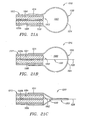
- FIG. 1A is a perspective view of a first preferred embodiment of an apparatus for cannulating a body lumen, in accordance with the present invention.
- FIG. 1B is a cross-sectional detail of a distal end of the apparatus of FIG. 1A, showing a guidewire inserted through the apparatus.
- FIG. 1C is a cross-section of the apparatus of FIG. 1A, taken along
line 1C-1C. - FIG. 2A is a perspective view of an alternative embodiment of the apparatus of FIG. 1A, having two degrees of steering.
- FIG. 2B is a cross-section of the apparatus of FIG. 2A, taken along
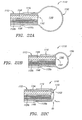
line 2B-2B. - FIG. 3A is a cross-sectional detail, showing an alternative embodiment of an apparatus for cannulating a body lumen including a balloon, in accordance with the present invention.
- FIGS. 3B and 3C are cross-sections of the apparatus of FIG. 3A, taken along lines 3B-3B, and 3C-3C, respectively.
- FIG. 4 is a cross-sectional detail, showing another alternative embodiment of an apparatus for cannulating a body lumen including a balloon, in accordance with the present invention.
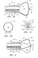
- FIGS 5A-5C are cross-sectional side views of an embodiment of a mechanically expandable member that may be substituted for an inflatable balloon in an apparatus, in accordance with the present invention.
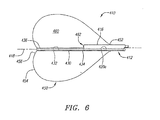
- FIG. 6 is a cross-sectional side view of a distal end of another embodiment of an apparatus for cannulating a body lumen, in accordance with the present invention.
- FIG. 7A is a side view of a catheter that may be included in the apparatus of FIG. 6.
- FIG. 7B is a side view detailing a set of light guides that may be included in the catheter of FIG. 7A.
- FIGS. 8A-8C are cross-sections of the catheter of FIG. 7, taken along
lines 8A-8A, 8B-8B, and 8C-8C, respectively. - FIGS. 9A-9C are cross-sections of the light guides of FIG. 7B, taken along
lines 9A-9A, 9B-9B, and 9C-9C, respectively. - FIG. 10 is a perspective detail of the apparatus of FIGS. 6 and 7A, with the balloon omitted for clarity.
- FIGS. 11A and 11B are exploded and perspective views of a optical fiber bundle having a lens attached thereto.
- FIGS. 12A-12D are partial cross-sectional views, showing a method for cannulating a body lumen communicating with a body cavity using the apparatus of FIGS. 6-10.
- FIGS. 13A-13D show representative images that may be seen during respective steps of the cannulation method shown in FIGS. 12A-12D.
- FIG. 14 is a cross-section detail showing a balloon attached to a tubular member.
- FIG. 15 is a partial cross-sectional side view of a distal end of yet another embodiment of an apparatus including an off-axis imaging element, in accordance with the present invention.
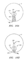
- FIG. 16A and 16B are end views of the apparatus of FIGS. 6 and 15, respectively, showing an improved field of view obtaining using an off-axis imaging element.
- FIGS. 17A-17F are perspective views of an alternative embodiment of an apparatus including a plurality of off-axis imaging elements.
- FIGS. 18A and 18B are cross-sectional side views of yet another embodiment of an apparatus for cannulating a body lumen, in accordance with the present invention.
- FIGS. 19A and 19B are cross-sectional side views, showing a method for cannulating a body lumen, in accordance with the present invention.
- FIGS. 20A-20C are cross-sectional side views of yet another embodiment of an apparatus for cannulating a body lumen, in accordance with the present invention.
- FIGS. 21A-21C are cross-sectional side views of still another embodiment of an apparatus for cannulating a body lumen, in accordance with the present invention.
- FIGS. 22A-22C are cross-sectional side views of yet another embodiment of an apparatus for cannulating a body lumen, in accordance with the present invention.
- FIGS. 23A and 23B are cross-sectional side views of alternative embodiments of an apparatus for cannulating a body lumen, in accordance with the present invention.
- FIGS. 24A and 24B are end views of the apparatus of FIGS. 23A and 23B, respectively.
- FIG. 25A is a cross-sectional side view of another embodiment of an apparatus for cannulating a body lumen, in accordance with the present invention.
- FIG. 25B is an end view of the apparatus of FIG. 25A.
- FIG. 26 is a perspective view of a computer that may be coupled to an optical imaging assembly of an apparatus, such as that shown in FIGS. 1A-1C.
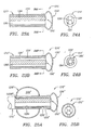
- FIG. 27A is a perspective view of yet another embodiment of an apparatus for cannulating a body lumen, including a plurality of oxygen sensors, in accordance with the present invention.
- FIG. 27B is a perspective detail, showing a catheter of the apparatus of FIG. 27A.
- FIG. 27C is a cross-sectional view of the apparatus of FIGS. 27A and 27B, taken along
line 27C-27C. - FIG. 27D is a detail of a tubular segment extending to an oxygen sensor of the apparatus of FIGS. 27A-27C.
- FIG. 28A is a cross-sectional side view of still another embodiment of an apparatus for cannulating a body lumen, including an oxygen center and an occlusion balloon.
- FIG. 28B is a cross-section of the apparatus of FIG. 28A, taken along line 28A-28A.
- FIGS. 29A-29C are cross-sectional views, showing a method for cannulating a coronary sinus ostium extending from a right atrium of a heart, in accordance with the present invention.
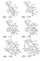
- FIGS. 30A-30C are details, showing alternate tips of a stabilization member that maybe included in the apparatus shown in FIGS. 29A-29C.
- Turning to the drawings, FIGS. 1A-1C show a first preferred embodiment of an
apparatus 10 for imaging a body lumen, e.g., for visualizing, accessing, and/or cannulating a body lumen from a body cavity (not shown). In a preferred embodiment, as explained further below, theapparatus 10 may be used for imaging a wall of a right atrium of a heart, e.g., for visualizing, accessing, and/or cannulating a coronary sinus ostium, although theapparatus 10 may be used for visualizing, accessing, and/or cannulating other body lumens as well. Generally, as shown in FIG. 1A, theapparatus 10 may include a catheter or otherelongate member 12, a balloon or otherexpandable member 50 on adistal end 16 of thecatheter 12, and animaging assembly 62 carried by thedistal end 16 of thecatheter 12 for imaging through theballoon 50. - The
catheter 12 generally is an elongate tubular body including aproximal end 14, adistal end 16 having a size and shape for insertion into a patient's body, and a centrallongitudinal axis 18 extending between the proximal and distal ends 14, 16. Thecatheter 12 may include one or more lumens 20 also extending between the proximal and distal ends 14, 16, e.g., a cannulation lumen 20a, aninflation lumen 20b, and one ormore lumens imaging assembly 62. - The
catheter 12 may be substantially flexible, semi-rigid, and/or rigid along its length, and may be formed from a variety of materials, including plastic, metal ,and/or composite materials, as is well known to those skilled in the art. For example, thecatheter 12 may be substantially flexible at thedistal end 16 to facilitate advancement through tortuous anatomy, and/or may be semi-rigid or rigid at theproximal end 14 to enhance pushability of thecatheter 12 without substantial risk of buckling or kinking. - Preferably, the
catheter 12 is steerable, i.e., thedistal end 16 may be controllably deflected transversely relative to thelongitudinal axis 18. In the embodiment shown in FIGS. 1A-1C, a single pullwire orother steering element 22 may be provided, e.g., within one of the lumens 20, for steering thedistal end 16 of thecatheter 12 in one transverse plane (thereby providing one degree of freedom). Alternatively, in another embodiment, such as that shown in FIGS. 2A and 2B, two pullwires 22' may be provided for steering the distal end 16' of the catheter 12' in two orthogonal planes (thereby providing two degrees of freedom). - The pullwire(s) 22 may be a cable, wire, band, and the like that may be slidably disposed within a lumen, such as the
inflation lumen 20b shown in FIG. 1C. The pullwire(s) 22 may be attached or otherwise fixed relative to thecatheter 12 at a location adjacent thedistal end 16, preferably offset radially outwardly from thecentral axis 18. Thus, when thepullwire 22 is pulled proximally, e.g., from theproximal end 14 of thecatheter 12, a bending force may be applied to thedistal end 16, causing thedistal end 16 to bend transversely relative to thecentral axis 18. - The
catheter 12 may also include a handle orother control mechanism 30 coupled to or otherwise provided on theproximal end 14 of thecatheter 12. Thehandle 30 may include one or more steering controls 32 that may be actuated to steer thedistal end 16 of thecatheter 12. For example, as shown in FIG. 1, adial 32 may be provided that may be coupled to thepullwire 22. Thedial 32 may be rotated to apply a proximal force on thepullwire 22, thereby bending thedistal end 16 of thecatheter 12. - Alternatively, as shown in FIGS. 2A and 2B, a
dial 32a' and atrigger 32b' may be provided on the handle 30' that may be coupled torespective pullwires 22a,' 22b.' Thus, the dial 32' may be rotated to bend the catheter 12' in a first direction and thetrigger 32b' may be pulled to bend the catheter 12' in a second direction, preferably substantially perpendicular to the first direction. The steering control(s) may be biased, e.g., to return thedistal end 32 or 32' of thecatheter 12 or 12' to a generally straight configuration when the control(s) is(are) released. Alternatively, each steering control may be coupled to a pair of opposing pullwires opposite one another relative to the central axis (not shown) such that actuating the control in one direction bends the distal end one direction, while actuating the control in an opposite direction bends the distal end in an opposite direction. It will be appreciated that other control mechanisms and/or steering arrangements may be provided, including one, two, or more degrees of freedom, as are well known to those skilled in the art. - The
handle 30 may also include ports and/or other connections for connecting other components to thecatheter 12. It will be appreciated that any known connectors may be provided for permanently or temporarily connecting components to thecatheter 12. For example, a luer lock connector may be used to connect tubing or other fluid-conveying components to thehandle 30. - As shown in FIG. 1A, a syringe or other source of
fluid 34, e.g., including saline, carbon dioxide, nitrogen, or air, may be connected via tubing 36 to theinflation lumen 20b (not shown, see FIG. 1C) for inflating theballoon 50. Thesyringe 34 may also provide a source of vacuum for deflating theballoon 50, as is known in the art. Another source offluid 38, e.g., saline, and/or a therapeutic or diagnostic agent, may be connected via tubing 40 to the cannulation lumen 20a for delivering fluid beyond thedistal end 16 of thecatheter 12. - In addition, an
access port 42 may also communicate with the cannulation lumen 20a, e.g., including a hemostatic seal and the like (not shown), for delivering one or more instruments (such asguidewire 80, shown in FIG. 1B) through the cannulation lumen 20a, as explained further below. Optionally, thehandle 30 may include a shape, size, and/or contour (not shown) for facilitating manipulating thecatheter 12 during use. - Returning to FIGS. 1A and 1B, a substantially
transparent balloon 50 may be provided on thedistal end 16 of thetubular member 12. Theballoon 50 may be expandable from a contracted condition (not shown) to an enlarged condition when fluid is introduced into an interior 60 of theballoon 50. In the embodiment shown, achannel 52 may extend through theballoon 50 that communicates with a lumen 20 of thecatheter 12, e.g., the cannulation lumen 20a. Preferably, thechannel 52 extends through theballoon 50 concentrically with thecentral axis 18, as best seen in FIG. 1B. - In an exemplary embodiment, the
balloon 50 may be formed from substantially noncompliant material, e.g., polytetrafluoroethylene (PTFE), expanded polytetrafluoroethylene (EPTFE), fluorinated ethylenepropylene (FEP), polyethylene teraphathalate (PET), urethane, olefins, and polyethylene (PE), such that theballoon 50 may expand to a predetermined shape when fully inflated to the enlarged configuration. Preferably, in the enlarged configuration, theballoon 50 may have adistal surface 54 that is substantially flat or otherwise configured for contacting a wall of a body cavity, such as the right atrium (not shown). Alternatively, as shown in FIGS. 19A and 19B, anapparatus 710 may be provided that carries aballoon 750 having a frustoconical shape and/or a convexdistal surface 754. - The material may be sufficiently flexible and/or elastic such that the
distal surface 54 may conform substantially to the wall of the body cavity. Preferably, theballoon 50 is also sufficiently noncompliant to displace blood or other fluid from between thedistal surface 54 and the wall of the body cavity to facilitate imaging the wall through theballoon 50, as explained further below. Alternatively, theballoon 50 may be formed from compliant and/or elastomeric materials, such as silicone, latex, isoprene, and chronoprene. - In the exemplary embodiment shown in FIG. 1B, the
balloon 50 may be formed from one or more panels that may be attached to one another, e.g., using an adhesive (such as an adhesive cured using ultraviolet ("UV") light), sonic welding, and/or heating, after lapping or butting adjacent panels together. Alternatively, theballoon 50 may be molded around or within a mold (not shown) having a desired shape for theballoon 50 in the enlarged condition. - The resulting
balloon 50 may include aproximal end 56 that may be attached to an outer surface of thecatheter 12, e.g., using an adhesive, heating, sonic welding, an interference fit, and/or an outer sleeve. Thechannel 52 may be formed from the same material as the rest of theballoon 50, and aproximal end 58 of the channel may be attached to thedistal end 16 of thecatheter 12, e.g., within or concentric with the cannulation lumen 20a. Alternatively, the channel may be formed from a semi-rigid or rigid tubular member, as shown in FIGS. 6-10, and described further below. - As best seen in FIG. 1B, the
interior 60 of theballoon 50 may have a generally annular shape that preferably communicates with theinflation lumen 20b (not shown, see FIG. 1C) of thecatheter 12. Substantially transparent inflation media, e.g., saline, carbon dioxide, nitrogen, air, and the like, may be introduced into the interior 60 of theballoon 50 to expand theballoon 50 towards the enlarged condition shown in FIGS. 1A and 1B. As used herein, "transparent" refers to any material and/or fluid that may permit sufficient light to pass therethrough in order to identify or otherwise visualize objects through the material and/or fluid. "Light" as used herein may refer to light radiation within the visible spectrum, but may also include other spectra, such as infrared ("IR") or ultraviolet ("UV") light. - Alternatively, the balloon and/or channel may have different configurations, such as that shown in FIGS. 3A-3C and 4. For example, as shown in FIGS. 3A-3C, an
apparatus 110 is shown that includes acatheter 112 that may include one or more lumens, e.g.,lumens catheter 112 that extends between a proximal end (not shown) to adistal end 116 of thecatheter 112. The lumen 120a may be a separate tubular member attached to thecatheter 112 or may be an integral part of thecatheter 112, e.g., formed as a single extrusion. - A
balloon 150 may be carried on thedistal end 116 of thecatheter 112 that defines an interior 160 communicating with an inflation lumen (not shown) that extends to the proximal end of thecatheter 112, similar to the previous embodiment. Achannel 152 may extend along a wall of theballoon 150 that communicates with the cannulation lumen 120a. Thechannel 152 may be defined by a panel of material attached to theballoon 150, similar to the materials and methods for makingballoon 50, as described above. Alternatively, an inner balloon panel may be provided within an outer balloon panel and the panels may be attached to one another, e.g., along one or more seams defining thechannel 152. - A nipple or
annular collar 157 may be provided on thedistal surface 154 of theballoon 150, e.g., to guide aguidewire 80 or other instrument out of theballoon 150, and/or to stabilize the device relative to a body lumen or other tissue structure (not shown). Thus, aguidewire 80 may be inserted into the cannulation lumen 120a from the proximal end of thecatheter 112, thechannel 152 guiding theguidewire 80 through theballoon 150 until it exits through thenipple 157 to a location beyond thedistal surface 152 of theballoon 150. - In another alternative, shown in FIG. 4, an
inner balloon 251 may be provided within an interior 260 of anouter balloon 250. Theinner balloon 251 may be expandable to a size and/or shape that is smaller than theouter balloon 250, thereby defining achannel 252 between theballoons guidewire 80 or other instrument (not shown) may be inserted into acannulation lumen 220a, e.g., extending along an outer surface of the catheter 212. Theguidewire 80 may enter thechannel 252 between theballoons nipple 257, similar to the embodiment shown in FIGS. 3A-3C. - In a further alternative, a balloon may be provided without a channel extending therethrough, as shown, for example, in FIGS. 20A-22C, and described further below.
- In yet another alternative, shown in FIGS. 5A-5C, an
apparatus 310 may be provided that includes a mechanicallyexpandable member 350 carried on adistal end 316 of acatheter 312. Aframe 352 may be coupled to thedistal end 316 that may support a substantially transparent,flexible membrane 354. Theframe 352 may include a plurality of members that are movable away from and towards one another, thereby causing themembrane 354 to move between contracted and enlarged conditions. - The
frame 352 may be actuated from a proximal end (not shown) of thecatheter 312, e.g., to cause theframe 352 to expand radially outwardly, as shown in FIGS. 5B and 5C. As theframe 352 expands, themembrane 354 may provide a substantiallytransparent surface 356 through which an optical imaging assembly, e.g., including anoptical fiber bundle 364 and/or alight guide 368, similar to that described further below, may obtain optical images. Optionally, an interior 358 of themembrane 354 may be filled with a substantially transparent fluid, similar to the balloons described above, to facilitate imaging through theexpandable member 350. - Returning to FIGS. 1A-1C, the
imaging assembly 62 generally includes anoptical imaging element 64 that is exposed within theinterior 60 of theballoon 50 for capturing light images through theballoon 50. In a preferred embodiment, theoptical imaging element 64 includes a bundle of optical fibers, e.g. a coherent image bundle, that extends between the proximal and distal ends 14, 16 of thecatheter 12, e.g., through thelumen 20d, as shown in FIG. 1C. Preferably, thefiber bundle 64 includes about ten thousand (10,000) optical fibers, although it may include between about one and fifty thousand (1,000-50,000) fibers in order to provide a desired resolution in the images obtained by thefiber bundle 64. - A
lens 66, e.g., a GRIN or self-oc lens, may be coupled to thefiber bundle 64 in order to focus light from beyond thedistal surface 54 of theballoon 50 onto thefiber bundle 64 in order to generate a resolved image at the proximal end of thefiber bundle 64, as is well known to those skilled in the art. Optionally, a directional prism or other optical element (not shown) may be provided for directing a field of view of thefiber bundle 64 as desired, as explained further below. - In addition, the
imaging assembly 62 may include one or more light guides 68 carried by thedistal end 16 of thecatheter 12 for delivering light into the interior 60 and/or through thedistal surface 54 of theballoon 50. Although a singlelight guide 68 is shown in FIGS. 1B and 1C, it will be appreciated that a plurality of light guides (not shown) may be provided in a common lumen or separate lumens (also not shown) within thecatheter 12. The light guide(s) 68 may include a plurality of optical fibers, e.g., formed from acrylic and the like, that may extend to theproximal end 14 of thecatheter 12. As shown in FIG. 1A, a source of light 70 may be coupled to the light guide(s) 68, e.g., via thehandle 30, for delivering light through the light guide(s) 68 and into theballoon 50. - A
device 72 may be coupled or otherwise provided at theproximal end 14 of theapparatus 10 for acquiring and/or capturing images obtained by theoptical imaging assembly 62. For example, one or more lenses (not shown) may be coupled to thefiber bundle 64 for focusing and/or resolving light passing through thefiber bundle 64, e.g., to pass the image to thedevice 72. Thedevice 72 may include a CCD, CMOS, and/or other device, known to those skilled in the art, e.g., to digitize or otherwise convent the light images from thefiber bundle 64 into electrical signals that may be transferred to a processor and/or display (not shown). - For example, as shown in FIG. 26, a
computer 82 may be coupled to the device 72 (not shown, see FIG. 1A), e.g., by acable 84. Alternatively, instead of thecomputer 82, other display or capture devices may be coupled to thedevice 72, such as a laptop computer, handheld or PDA device, a computer terminal, a LCD display, standard video monitor, and the like (not shown), to display and/or store the images acquired from thefiber bundle 64. Optionally, the computer 82 (or other capture device) may provide electrical power to thedevice 72,light source 70, and/or other components of theapparatus 10. - For a cable connection between the
device 72 and thecomputer 82, various protocols may be used, such as USB, Firewire, standard video signal protocols, and the like. Alternatively, thecomputer 82 may be coupled to thedevice 72 via a wireless connection, for example, including one or more transmitters and/or receiving using radio frequency signals, Bluetooth, infrared links, and the like. - In addition, the
computer 82 may run software modules to enable capture, viewing, and/or manipulation of images obtained by theoptical imaging assembly 62. Thecable 84, the handle 30 (not shown, see FIG. 1A), or other component of theapparatus 10 may include interface features 86, such as buttons, toggles, scroll bars, dials, and the like, to facilitate interfacing with software running on thecomputer 82. Functions that may be performed using theinterface 86 may include launching image acquisition software on thecomputer 82, initiating or terminating image capture, initiating still frame capture, reviewing or displaying captured images, etc. Thehandle 30 or other component of theapparatus 10 may also contain feedback features, e.g., one or more LEDs or LCDs, to provide feedback from software on thecomputer 82, e.g., related to the status of connection(s) between thecomputer 82 and theapparatus 10, the power status of theapparatus 10, the function of theapparatus 10, and the like. - Optionally, the
apparatus 10 may include additional data acquisition features, such as a microphone (not shown), e.g., allowing procedure notes to be dictated during an imaging procedure or allowing theapparatus 10 and/orcomputer 10 to be controlled by voice commands. In addition or alternatively, drivers and/or software may be stored on a memory chip (not shown) in theapparatus 10 that may be uploaded to thecomputer 82 when connected to theapparatus 10. When a complex interface is used to connect theapparatus 10 to thecomputer 82 or other display device, theapparatus 10 and/or thecomputer 82 may be capable of disabling the complex interface and enable simple video output. - Turning to FIGS. 6-10, another preferred embodiment of an
apparatus 410 is shown for visualizing and/or cannulating a body lumen. Similar to the previous embodiments, theapparatus 410 generally includes acatheter 412, aballoon 450 carried by thecatheter 412, and animaging assembly 462 for imaging through theballoon 450. - Also, similar to the previous embodiments, the
catheter 412 may be an elongate tubular body including aproximal end 414, adistal end 416, and a centrallongitudinal axis 418 extending therebetween. Thecatheter 412 may be substantially flexible, semi-rigid, and/or rigid along its length, and may be formed from a variety of materials, including plastic, metal, and/or composite materials. Thecatheter 412 may have a diameter between about five and ten French (1.67-3.33 mm), and preferably between about six and eight French (2.00-2.67 mm). - The
catheter 412 may include one or more lumens 420 also extending between the proximal anddistal ends cannulation lumen 420a, aninflation lumen 420b, and one ormore lumens 420c-f for theimaging assembly 462 and/or one or more pullwires orother steering elements 422. In addition, thecatheter 412 may include a handle (not shown) and/or other components, e.g., sources of fluid, a light source, an image capture device, and the like (also not shown) on theproximal end 414, similar to the other embodiments described herein. - Preferably, the
catheter 412 includes multiple extrusions that are attached to one another to provide a desired length. For example, thecatheter 412 may include a proximal portion 412a having a first cross-section, shown in FIGS. 8A and 8B, and adistal portion 412b having a second cross-section, shown in FIG. 8C. The proximal portion 412a may have a length between about nine and thirty six inches (22-90 cm), and preferably between about eighteen and twenty eight inches (45-70 cm). - The proximal portion 412a preferably includes three lumens, a
cannulation lumen 420a, aninflation lumen 420b, and anaccessories lumen 420c. Thecannulation lumen 420a may provide a path for a guidewire or other instrument, fluid, and the like to pass between the proximal anddistal ends catheter 412. Optionally, atube 424, e.g., made from polyamide and the like, may be provided within thecannulation lumen 420a, e.g., to reinforce thecannulation lumen 420a and/orcatheter 412. Theinflation lumen 420b may communicate with an interior 460 of theballoon 450, similar to the previous embodiments, for delivering substantially transparent inflation media into theballoon 450. Theaccessories lumen 420c may carry a plurality of components, e.g., an optical imaging (fiber optic)bundle 464, pull-wire 422, and/or a set of light guides 468, similar to the previous embodiments described above. - With reference to FIGS. 7A and 8C, the
distal portion 412b may have a length between about 25.4-101.6 millimeters (mm), and preferably between about 50.8-76.2 millimeters (mm). Thedistal portion 412b may be substantially permanently attached to the proximal portion 412a, e.g., using a lap or butt joint, and/or an adhesive, interference fit, heating, and/or sonic welding. Thedistal portion 412b may include continuations of thecannulation lumen 420a andinflation lumen 420b from the proximal portion 412a. In addition, thedistal portion 412b may include alight guide lumen 420d, a fiber optic lumen 420e, and apullwire lumen 420f that may communicate with theaccessories lumen 420c when the proximal anddistal portions 412a, 412b are attached to one another. - Preferably, the fiber optic lumen 420e is located as far away from the
cannulation lumen 420a as possible in order to maximize a field of view of thefiber bundle 464 received therein. For example, as shown in FIG. 8C, thedistal portion 412b may include a ridge 421 extending axially along an outer surface of thedistal portion 412b, thereby maximizing a distance that the fiber optic lumen 420e may be disposed away from thecannulation lumen 420a. When thefiber bundle 464 is inserted into thecatheter 412, thefiber bundle 464 may be received in the fiber optic lumen 420e in thedistal portion 412b, and in theaccessories lumen 420c in the proximal portion 412a. Thefiber bundle 464 may be secured at one or more locations within thelumens 420e, 420c, e.g., using an adhesive and the like. Thus, the location of thefiber bundle 464 may be fixed in thedistal portion 412b to stabilize its field of view relative to thecatheter 412. - The
pullwire lumen 420f may also be located as far away from thecentral axis 418, e.g., due to another ridge extending the outer surface. This arrangement may maximize a bending force applied to thecatheter 412 when thepullwire 422 is pulled proximally. - Turning to FIGS. 7B and 9A-9C, the set of light guides 468 may be received in the
accessories lumen 420c in the proximal portion 412a and in thelight guide lumen 420d in thedistal portion 412b. The set of light guides 468 may include between about one and twenty five, and preferably between about four and ten, elongate light guides. Each of the light guides 468 may be formed from a substantially transparent acrylic fiber or other light transmitting material, e.g., having a diameter between about twenty five micrometers and one millimeter (25 µm-1 mm), and preferable between about two hundred fifty and five hundred micrometers (250-500 µm). - At the
proximal end 414 of thecatheter 412, the light guides 468 may be substantially cylindrical, while towards thedistal end 416 of thecatheter 412, the light guides 468 may be tapered and/or flattened. For example, the light guides 468 may taper within a few inches of theproximal end 414 of thecatheter 412, preferably reducing an overall cross-section of the light guides 468 by as much as fifty percent (50%). The light guides 468 may be disposed loosely within theaccessories lumen 420c of the proximal portion 412a. - The enlarged size of the light guides 468 at the
proximal end 414 of thecatheter 412 may facilitate connecting the light guides 468 to a light source (not shown), as will be appreciated by those skilled in the art. Optionally, exposed lengths (not shown) of the light guides 468 beyond theproximal end 414 of thecatheter 412 may be further enlarged to facilitate such connections. For example, if the light guides 468 are acrylic fibers, heat may be applied, e.g., up to one hundred seventy degrees Fahrenheit (170 °F), to cause the light guides 468 to shorten. The acrylic material may increase in diameter as it shortens, thereby increasing the diameter of the light guides 468 by as much as three times as they shorten. This may allow the light guides 468 to be columnated and connected to a light source without requiring a lens (not shown). - As the light guides 468 transition from the proximal portion 412a to the
distal portion 412b, they may be linearly aligned and/or secured to each other, e.g., using an epoxy or other adhesive, and/or by reflowing the fiber material, such that surfaces of adjacent fibers are bonded at adjacent contact points. To align the light guides 468 in a desired orientation within thedistal portion 412b, the light guides 468 may be received in an axial ridge or slot 423 within thedistal portion 412b, as shown in FIG. 8C. - The bonded array of light guides 468 may provide a hinge, i.e., biasing the
distal portion 412b of thecatheter 412 to bend in a predetermined direction. Specifically, the light guides 468 may provide a higher bending moment along a bond axis "x" (shown in FIG. 9C), while exhibiting a much lower bending moment along an axis orthogonal to the bond axis "x." As thepullwire 422 is pulled proximally, the force may be transferred to thedistal portion 412b of thecatheter 412. Because of the asymmetric bending moments created by the light guides 468, thedistal portion 412b of thecatheter 412 may bend in one plane orthogonal to the bond axis "x," i.e., towards thepullwire 422, while resisting bending along the bond axis "x." This may cause thecatheter 412 to curve from a location where the pullwire 422 transitions from being located at the center of the catheter 412 (e.g., as shown in FIG. 8A) to a location on thedistal end 416 where thepull wire 422 is fixed (e.g., as shown in FIG. 8C). - Turning to FIGS. 10-11B, a
bundle 464 of optical fibers may be provided, similar to the embodiments described above. Preferably, alens 466 is coupled to thefiber bundle 464, e.g., a GRIN or self-oc lens, as described above. For example, as shown in FIGS. 11A and 11B, asleeve 467, e.g., shrink wrap and the like, may be provided that may be secured around thelens 466 and theoptical imaging bundle 464. Optionally, a fluid or other material (not shown) may be provided between thelens 466 and theoptical imaging bundle 464 to minimize losses and/or reflection at the transition, as is known to those skilled in the art. - Turning to FIG. 10 with continued reference to FIG. 6, a
tubular extension 430 may extend from thedistal end 416 of thecatheter 412. Thetubular extension 430 may include alumen 432 extending between proximal anddistal ends tubular extension 430. Preferably, thetubular extension 430 has a substantially smaller diameter or other cross-section than thedistal end 416 of thecatheter 412. - The
proximal end 434 of thetubular extension 430 may be attached to thedistal end 416 of thecatheter 412 such that it is coextensive with thecannulation lumen 420a. Thus, an instrument or fluid introduced through thecannulation lumen 420a may pass freely through thelumen 432 of thetubular extension 430. In addition, attaching thetubular extension 430 eccentrically to thecatheter 412 opposite theoptical imaging bundle 464 may minimize the extent that thetubular extension 430 obstructs the field of view of theoptical imaging bundle 464. - In one embodiment, the
proximal end 434 of thetubular extension 430 may be at least partially received in thecannulation lumen 420a or in a recess (not shown) concentric with thecannulation lumen 420a. Alternatively, theproximal end 434 of thetubular extension 430 may be butted against thedistal end 416 of thecatheter 412. In addition or alternatively, the tubular extension 4430 may be bonded to thecatheter 412, e.g., using an adhesive, heating, sonic welding, and the like. - The
balloon 450 may include aproximal end 452 attached to thedistal end 416 of thecatheter 412 and adistal end 456 attached to the distal end of thetubular extension 430. Theproximal end 452 of theballoon 450 may be secured to the outer surface of thecatheter 412, e.g., using an adhesive, heating, an interference fit, an outer collar (not shown), and the like, similar to the other embodiments described herein. - Turning to FIG. 14, the
distal end 456 of theballoon 450 may be attached to thedistal end 436 of thetubular extension 430 such that theballoon 450 at least partially inverts on itself. This may facilitate close contact between theballoon 450 and a tissue surface being viewed (not shown), which may reduce optical distortion and/or facilitate clearing fluid from between theballoon 450 and the contacted tissue surface. In addition, this arrangement may prevent thedistal end 436 of thetubular extension 430 from extending substantially beyond thedistal surface 454 of theballoon 450. - Similar to the previous embodiments, the
balloon 450 may be expandable from a contracted condition, as shown in FIG. 12A, to an enlarged condition, as shown in FIGS. 6 and 12B-12D. In the enlarged condition, theballoon 450 may define a substantially flatdistal surface 454 that may facilitate imaging tissue structures beyond theballoon 450 with theoptical imaging bundle 464. Optionally, theballoon 450 may include a reflective coating (not shown) on an inside surface thereof, e.g., the proximal surface(s) opposite thedistal surface 454, e.g., to concentrate light towards thedistal surface 454 that may otherwise reflect or pass proximally through theballoon 450. - Turning to FIGS. 12A-13D, a method is shown for cannulating a body lumen communicating with a body cavity, e.g., a
coronary sinus ostium 90 extending from aright atrium 92. Although theapparatus 410 shown is similar to that shown in FIGS. 6-10, other embodiments described herein may be used to complete similar methods. Initially, as shown in FIG. 12A, theapparatus 410 may be provided with theballoon 450 in the contracted condition. If theballoon 450 is formed from noncompliant and/or inflexible material, theballoon 450 may be folded, twisted, or otherwise compressed into the contracted condition. With the balloon collapsed, the fiberoptic imaging bundle 464 may provide an unfocused image, as shown in FIG. 13A. - The
distal end 416 of theapparatus 410 may be introduced into a patient's body using conventional methods used for delivering catheters or other instruments. For example, theapparatus 410 may be introduced percutaneously into the patient's vasculature from a peripheral vein, such as the femoral vein. Theapparatus 410 may be advanced endoluminally, e.g., into the vena cava (not shown) and into theright atrium 92 of the heart. Optionally, theapparatus 410 may be carried within a sheath, catheter, or other delivery device (not shown) that may protect theballoon 450 or otherwise facilitate advancing theapparatus 410 through the patient's vasculature. - Once located within the
right atrium 92, theballoon 450 may be expanded, as shown in FIGS. 6 and 12B (e.g., after deploying at least thedistal end 416 from any delivery device). Theapparatus 410 may then be manipulated to place thedistal surface 454 of theballoon 450 into contact with thewall 94 of the heart within theright atrium 92, as shown in FIG. 12B. Optionally, this manipulation may involve steering thedistal end 416 of theapparatus 450, e.g., using one or more pullwires or other steering mechanisms actuated from the proximal end (not shown) of theapparatus 410. - In addition or alternatively, other imaging systems may be used to monitor the
apparatus 410 to facilitate accessing thecoronary sinus 90. For example, external imaging systems, such as fluoroscopy, ultrasound, magnetic resonance imaging (MRI), and the like, may provide feedback as to the location and/or relative position of thedistal end 416 of theapparatus 412. Thedistal end 416 may include markers, e.g., radiopaque bands and the like (not shown), that may facilitate such imaging. External imaging may ensure that theapparatus 410 is generally oriented towards thecoronary sinus ostium 90 before optical images are acquired and theapparatus 410 is manipulated more precisely. - With the
distal surface 454 ofballoon 450 placed against thewall 94 of the heart, thefiber bundle 464 may be activated to image thewall 94. Sufficient distal force may be applied to theapparatus 410 to squeeze blood or other fluid from between thedistal surface 454 and thewall 94, thereby clearing the field and facilitating imaging thewall 94. Optionally, a substantially transparent fluid, e.g., saline, may be delivered through thecatheter 412 and thetubular extension 430 to further direct blood or other fluid away from thedistal surface 454 of theballoon 450 or otherwise clear the field of view of thefiber bundle 464. - Using the
fiber bundle 464 to image thewall 94, theapparatus 410 may be moved along thewall 94 until a target structure is within the field of view. For example, as shown in 13B, thecoronary sinus ostium 90 may be seen entering the field of view, as theballoon 450 approaches thecoronary sinus ostium 90, as shown in FIG. 12B. Theapparatus 410 may be moved further, as shown in FIG. 12C, until thecoronary sinus ostium 90 is centered in the field of view, as shown in FIG. 13C. Preferably, the center of the field of view corresponds to thecentral axis 418 of theapparatus 410, e.g., aligning thetubular extension 430 with thecoronary sinus ostium 90. - Once the
coronary sinus ostium 90 is aligned with the tubular extension, theballoon 450 may be partially deflated, as shown in FIG. 12D, and thetubular extension 430 may be advanced at least partially into thecoronary sinus 90. Thus, thetubular extension 430 may stabilize theapparatus 410 relative to thecoronary sinus 90. One ore more instruments, e.g., a guidewire (not shown), may be advanced into thecoronary sinus 90 to access one or more coronary veins (also not shown) via thecoronary sinus 90. Alternatively, theballoon 450 may be fully deflated, and thetubular extension 430 may be advanced into thecoronary sinus 90 to guide thedistal end 416 of theapparatus 410 into thecoronary sinus 90 and/or into the coronary veins. - In one embodiment, a guidewire may provide a rail over which other instruments may be advanced into the coronary veins. For example, before or after the guidewire has been placed within a target coronary vein, the
apparatus 410 may be removed from theright atrium 92 and/or completely from the patient's body. A catheter or sheath (not shown) may be advanced over the guidewire to access the coronary vein and/or to perform a procedure there. For example, with the catheter or sheath placed within the target coronary vein, the guidewire may be removed, and an electrical lead, e.g., a pacing lead for a pacemaker (also not shown), may be advanced into the coronary vein for implantation. - In one embodiment, an expandable sheath (not shown) may be delivered via the
tubular extension 430 into the coronary veins, e.g., to deliver a pacing lead. Exemplary sheath apparatus and methods are disclosed in co-pending application Serial No.10/423,321, filed April 24, 2003 apparatus 410 may be used to deliver fluids or other materials into thecoronary sinus 90. For example, a radiopaque fluid may be retro-perfused into thecoronary sinus 90, e.g., for obtaining a venogram of one or more coronary veins within the heart. - Turning to FIG. 15, yet another embodiment of an
apparatus 510 is shown for visualizing and/or cannulating a body lumen, e.g., acoronary sinus ostium 90, similar to the previous embodiment. Similar to the embodiment shown in FIGS. 6-10, theapparatus 510 generally includes acatheter 512, aballoon 550 carried by thecatheter 512, and animaging assembly 562 for imaging through theballoon 550. Thecatheter 512 may be an elongate tubular body including a proximal end (not shown), adistal end 516, and a central longitudinal axis 518 extending therebetween. - The
catheter 512 may include one or more lumens 520 also extending between the proximal anddistal ends 514, 516, e.g., acannulation lumen 520a, an inflation lumen (not shown), and one or more lumens (also not shown) for theimaging assembly 562 and/or one or more pullwires or other steering elements (also not shown). Atubular extension 530 may extend from thedistal end 516 of thecatheter 512, including alumen 532 extending between proximal anddistal ends tubular extension 430 that preferably communicates with thecannulation lumen 520a. - Similar to the previous embodiments, the
balloon 550 may be expandable from a contracted condition (not shown) to an enlarged condition, shown in FIG. 15. In the enlarged condition, theballoon 550 may define a substantially flatdistal surface 554 that may facilitate imaging tissue structures beyond theballoon 550 with theimaging assembly 562. - Unlike the previous embodiment, at least part of the
imaging assembly 562 may be provided on anarm 568 that is extendable from thedistal end 516 of thecatheter 512. For example, a fiberoptic imaging bundle 564 may be carried by thearm 568, while one or more light guides (not shown) may be provided on thedistal end 516 of thecatheter 512, similar to theapparatus 410 shown in FIGS. 6-10. Alternatively, one or more light guides (not shown) may be carried by thearm 568, in addition or instead of thefiber bundle 564. - A lens and/or
prism 566 may also be carried by thearm 568 for focusing and/or redirecting the field of view of thefiber bundle 564. Preferably, a lens andprism 566 may be provided for centering the field of view towards a location where the central axis 518 intersects thedistal surface 554 of theballoon 550. In addition or alternatively, thearm 568 may be bent to orient thefiber bundle 564 in a desired direction. - The
arm 568 may be movable from a retracted profile (not shown), wherein thearm 568 lies close to or against thedistal end 516 of thecatheter 512, and an extended profile, shown in FIG. 15, wherein thearm 568 extends laterally away from thedistal end 516 of thecatheter 512. In one embodiment, thearm 568 may be biased to the extended profile, and may be restrained in the retracted profile, e.g., by theballoon 550 when theballoon 550 is deflated to the contracted condition. Alternatively, thearm 568 may be movable freely relative to thecatheter 512, and a tether (not shown) may be connected to thearm 568 that is also connected to theballoon 550. Thus, as theballoon 550 expands, the tether may pull thearm 568 radially outwardly to the extended profile. In yet another alternative, thearm 568 may be extended and/or retracted using an actuator (not shown) operable from the proximal end of theapparatus 510. - The
apparatus 510 may be used in methods similar to theapparatus 410 shown in FIGS. 6-10. One advantage of theapparatus 510 is that it may maximize the field of view - of the
fiber bundle 564, as compared to theapparatus 410. For example, as shown in FIG. 16A, the apparatus 410 (shown in FIGS. 6-10) may include an fiberoptic imaging bundle 464 that is carried by thecatheter 412 opposite atubular extension 430. Because thetubular extension 430 extends distally into the field of view "F" of thefiber bundle 464, a blind spot BS1 is created. Because thefiber bundle 464 is disposed as far away as possible from thetubular segment 430 on thecatheter 410, the blind spot BS1 is minimized compared to moving the fiber bundle and tubular extension closer to one another (not shown), as will be appreciated by those skilled in the art. - Turning to FIG. 16B, a field of view "F" of the
apparatus 510 of FIG. 15 is shown, which has a similar diameter compared to theapparatus 410, assuming comparablysized fiber bundles fiber bundle 564 is carried by the arm 568 (see FIG. 15), it is offset radially away from thetubular extension 530, thereby reducing a blind spot BS2 as compared to the blind spot BS1 shown in FIG. 16A. Thus, the arrangement of thefiber bundle 564 of theapparatus 510 of FIG. 15 may maximize the field of view, thereby reducing the risk of tissue structures passing through the blind spot undetected. - Turning to FIGS. 17A-17F, another embodiment of an
apparatus 610 is shown that includes acatheter 612, aballoon 650 carried by thecatheter 612, and an imaging assembly 662 for imaging through theballoon 650. Theapparatus 610 differs from theprevious apparatus 510 shown in FIG. 15, including a pair of fiber optic imaging bundles 664 carried byarms 668. Thearms 668 may be extendable from a retracted profile, e.g., as shown in FIG. 17A to an extended profile, as shown in FIGS. 17C-17F. - In addition, the
balloon 650 may be formed from an elastomeric material, such as silicone, latex, isoprene, and chronoprene, such that theballoon 650 may expand outwardly in proportion to the amount of fluid delivered into an interior 660 of theballoon 650. Preferably, theballoon 650 is attached to atubular extension 630 extending from thedistal end 616 of thecatheter 612 such that, as theballoon 650 expands, adistal surface 654 of theballoon 650 may become substantially flat and/or at least partially evert, as shown in FIGS. 17E and 17F. This expanded configuration may facilitate increased contact between thedistal surface 654 and a tissue structure (not shown) to be imaged. - As the
balloon 650 expands, it may allow thearms 668 to expand radially outwardly to the extended profile. In addition, thearms 668 may be bent such that thefiber bundle 664 is oriented substantially distally, as shown in FIGS. 17B-17F. One or more light guides 666 may be provided on thedistal end 616 of thecatheter 612, similar to the previous embodiments for providing light to illuminate thedistal surface 654 of theballoon 650 and beyond. Optionally, one ormore electrodes 617 may be provided on thedistal end 616 of the catheter, e.g., for measuring electrical potential and/or to serve as radiopaque markers to facilitate imaging theapparatus 610. - The
apparatus 610 may be delivered into a body cavity, e.g., a right atrium, similar to the previous embodiments for imaging a body lumen, e.g., a coronary sinus ostium not shown). The pair offiber bundles 664 may increase a field of view of theapparatus 610, possibly eliminating any blind spots created by thetubular extension 630, as compared to theapparatus 510 described above and including a single offsetfiber bundle 564. - Turning to FIGS. 18A and 188, an alternative embodiment of an
apparatus 810 is shown that includes acatheter 812, aballoon 850 carried on adistal end 516 of thecatheter 812, and animaging assembly 862 for imaging through theballoon 850. Theballoon 850 may be expandable between contracted and enlarged conditions, similar to other embodiments described elsewhere herein. Theapparatus 810 may include one or more additional or different components or features (not shown) described elsewhere herein, similar to the other embodiments. - In addition, the
apparatus 810 may include an elongatetubular member 830 extending from a proximal end (not shown) of thecatheter 812 to thedistal end 816, and through an interior 860 of theballoon 850. Thetubular member 830 may include a lumen 832 extending therethrough through which an instrument, e.g., aguidewire 80, and/or a fluid (not shown) may be delivered to a location distally beyond theballoon 850. Thetubular member 830 may be substantially flexible, but is preferably semi-rigid or substantially rigid. - The
apparatus 810 may be used to deliver one or more instruments or fluids into a body lumen, similar to the other embodiments described herein. In one embodiment, thetubular member 830 is fixed relative to thecatheter 512. In another embodiment, similar to that described below, thetubular member 830 may be slidable axially, i.e., distally and/or proximally, relative to thecatheter 512 for changing a shape of theballoon 850 during a procedure. - Turning to FIGS. 19A and 19B, another embodiment of an
apparatus 710 for cannulating a body lumen, such as acoronary sinus ostium 90, is shown. Similar to the previous embodiments, theapparatus 710 may include acatheter 712, aballoon 750 carried by thecatheter 712, and an imaging assembly (not shown for simplicity) for imaging through theballoon 750. - In addition, the
apparatus 710 may include anelongate cannulation member 730 that is slidably received in alumen 720a of thecatheter 712. Thecannulation member 730 may be an elongate tubular body, including a lumen 832 extending between a proximal end (not shown) and a distal end 836 of thecannulation member 730. Thecannulation member 730 may be substantially flexible, semi-rigid, and/or rigid, similar to the catheters described above. - The
balloon 750 may be expandable between a contracted condition (not shown), and an enlarged condition, shown in FIGS. 19A and 19B. In the enlarged condition, theballoon 750 may assume a frustoconical shape. In addition, theballoon 750 may include a convexdistal surface 754 or a substantially flat distal surface (not shown) in the enlarged condition. Theballoon 750 may include achannel section 756 that may be attached to thecannulation member 730, e.g., adjacent itsdistal end 736. Thechannel section 756 may at least partially evert into an interior 760 of theballoon 750, as shown in FIG. 19A, and/or may extend beyond thedistal surface 754 of theballoon 750, depending upon the axial position of thecannulation member 730. - During use, the
cannulation member 730 may be provided initially retracted such that thechannel section 756 of theballoon 750 everts into theinterior 760 of theballoon 750, as shown in FIG. 19A. With theballoon 750 collapsed in the contracted condition, theapparatus 710 may be introduced into a patient's body, e.g., until the distal end 716 is located within aright atrium 92 of the patient's heart, similar to the previous embodiments. Theballoon 750 may be expanded, e.g., by delivering a substantially transparent fluid into the interior 760 until theballoon 750 assumes the enlarged condition, as shown in FIG. 19A. - The
distal surface 754 of theballoon 750 may be placed against thewall 94 of the heart, and manipulated while imaging through thedistal surface 754 with the imaging assembly. Preferably, the distal end 836 of thecannulation member 730 may remain flush or proximal to thedistal surface 754, thereby allowing thewall 94 to be imaged through theballoon 750. A more proximal position may prevent thecannulation member 730 from interfering substantially with a field of view of the imaging assembly, which may facilitate aligning theapparatus 710 with thecoronary sinus ostium 90. - When the
apparatus 710 is aligned with thecoronary sinus ostium 90, as shown in FIG. 19B, thecannulation member 730 may be advanced distally into thecoronary sinus 90. Optionally, theballoon 750 may be at least partially deflated as or after thecannulation member 730 is advanced, thereby allowing the distal end 716 of thecatheter 712 to be inserted into thecoronary sinus 90 as well. - An instrument, e.g., a guidewire, catheter, and the like (not shown), may be delivered through the
lumen 732 of thecannulation member 730, e.g., to perform a diagnostic and/or therapeutic procedure within a region accessed, e.g., within a coronary vein (not shown). Once the procedure(s) is(are) completed, theapparatus 710 may be removed from the patient's body. - Turning to FIGS. 20A-20C, still another embodiment of an
apparatus 910 is shown for visualizing and/or cannulating a body lumen (not shown). Similarly to the previous embodiments, theapparatus 910 may include acatheter 912, aballoon 950 carried by adistal end 916 of thecatheter 912, and animaging assembly 962, similar to the previous embodiments. - Unlike the previous embodiments, the
balloon 950 may not include a channel extending therethrough, and instead includes an interior 960 that is substantially enclosed. A lumen, e.g., aninflation lumen 920b, may extend from a proximal end (not shown) of thecatheter 912 to thedistal end 916 that communicates with theinterior 960 of theballoon 950. In addition, thecatheter 912 may include acannulation lumen 920a that may extend along an outer surface of thecatheter 912 through which an instrument, e.g., guidewire 80, and/or a fluid may be delivered to thedistal end 916 of thecatheter 912 outside theballoon 950. - The
apparatus 910 may also include anelongate member 930 that is slidable within theinflation lumen 920b or optionally through another lumen (not shown) that communicates with theinterior 960 of theballoon 950. Preferably, theelongate member 930 includes a substantially bluntdistal end 936 that may be advanced into theinterior 960 of theballoon 950. For example, theelongate member 930 may be inserted into theinflation lumen 920b from the proximal end of thecatheter 912, or theelongate member 930 may not be removable from thecatheter 912, and, instead, may be slidable in a limited range within theinflation lumen 920b. - During use, the
apparatus 910 may be advanced into a patient's body, e.g., into a right atrium of a heart or other body cavity (not shown) with theballoon 950 collapsed, similar to the previous embodiments. Within the body cavity, theballoon 950 may be expanded, as shown in FIG. 20A, such that theballoon 950 defines a substantially flatdistal surface 954. Thedistal surface 954 may be placed against a wall of the body cavity, and manipulated, e.g., steered and/or otherwise moved, until a target body lumen, e.g., a coronary sinus ostium (not shown) enters the field of view of a fiberoptic imaging bundle 964 of theimaging assembly 962, similar to the previous embodiments. - Once the target body lumen is located and the
apparatus 910 is aligned with the body lumen, theelongate member 930 may be advanced through theinflation lumen 920b and into theinterior 960 of theballoon 950. Thedistal end 936 of theelongate member 930 may contact thedistal surface 954 of theballoon 950, whereupon, further distal movement of theelongate member 930 may cause theballoon 950 to change shape, as shown in FIGS. 20B and 20C. Because of the substantially blunt shape of thedistal end 936 of the elongate member, theballoon 950 may be changed without substantial risk of puncturing or otherwise damaging theballoon 950. - For example, the
elongate member 930 may be advanced to elongate theballoon 950 and/or reduce a diameter or other cross-section of theballoon 950. This may at least partially introduce theballoon 950 into the body lumen, e.g., the coronary sinus, thereby stabilizing theapparatus 910 relative to the body lumen. Alternatively, theelongate member 930 may reduce a cross-section of theballoon 950, thereby allowing an instrument, e.g., aguidewire 80, to be advanced through thecannulation lumen 920a and past theballoon 950 without substantial risk of puncturing or otherwise damaging theballoon 950. Theguidewire 80 may be advanced into the body lumen, whereby additional instruments (not shown) may be advanced over theguidewire 80 into the body lumen, as described above. - Alternatively, as shown in FIGS. 21A-21C, an
apparatus 1010 may be provided that includes aballoon 1050 carried by acatheter 1012, and animaging assembly 1062 for imaging through theballoon 1050. Similar to the previous embodiments, substantially transparent fluid, e.g., saline, may be introduced into theballoon 1050 to expand theballoon 1050 and allow adistal surface 1054 to be placed into contact with tissue structures, e.g., a wall of a heart, similar to the previous embodiments. - An elongate member, e.g., a
guidewire 1030, may be inserted through aninflation lumen 1020b of thecatheter 912 into the interior of theballoon 1050, e.g., after theballoon 950 has been inflated and/or used to identify and/or locate a body lumen (not shown), similar to the previous embodiment. As shown in FIG. 21B, theguidewire 1030 maybe advanced until adistal end 1036 of theguidewire 1030 punctures theballoon 1050 and passes therethrough into the target body lumen. Optionally, the distal end 1032 of theguidewire 1030 may be sharpened or otherwise adapted to facilitate puncturing theballoon 1050. - As the inflation fluid escapes through the puncture created in the
balloon 1050, theballoon 1050 may collapse, as shown in FIG. 21C. Theguidewire 1030 may be advanced into the body lumen, and one or more instruments (not shown) may be advanced over the guidewire, e.g., after removing theapparatus 1010, as described above. - In a further alternative, shown in FIGS. 22A-22C, an
apparatus 1110 may be provided that includes acatheter 1112, aballoon 1150 carried on adistal end 1116 of thecatheter 1112, and animaging assembly 1162 for imaging through theballoon 1150. Similar to the previous embodiment, an inflation lumen 120b extends through thecatheter 1112 to communicate with an interior 1160 of theballoon 1150. Unlike the previous embodiment, acannulation lumen 1120a extends along an outer surface of thecatheter 1112. - During use, as shown in FIG. 22A, the
apparatus 1110 may be introduced into a body cavity (not shown), whereupon theballoon 1150 may be expanded and contacted with a wall of the body cavity for imaging tissue structures therethrough. When theapparatus 1110 is aligned with a body lumen extending from the body cavity, theballoon 1150 may be at least partially deflated, as shown in FIGS. 22B and 22C. Once thecannulation lumen 1120a is not obstructed by theballoon 1150, aguidewire 80 or other instrument may be advanced through thecannulation lumen 1120a past theballoon 1150, and preferably into the body lumen, similar to the procedures described above. - Turning to FIGS. 23A-25B, yet another embodiment of an
apparatus 1210 is shown for visualizing and/or cannulating a body lumen, e.g., a coronary sinus ostium extending from a right atrium of a heart (not shown). Similar to the previous embodiments, theapparatus 1210 includes acatheter 1212 carrying animaging assembly 1262 on itsdistal end 1216, which may include a fiberoptic imaging bundle 1264 and one or more light guides 1268, as described above. - In addition, the
apparatus 1210 may include asolid bulb 1250 carried on thedistal end 1216 of thecatheter 1212. Thebulb 1250 may be formed from a substantially rigid or semi-rigid material that is substantially transparent, e.g., acrylic, polycarbonate, polymethlymethacrylate (PMMA), and nylon. Thebulb 1250 may define an interior 1260 that may be filled with substantially transparent fluid, e.g., saline, to facilitate imaging through thebulb 1250 using theimaging assembly 1262. - In the embodiment shown in FIGS. 23A and 24A, the fiber
optic imaging bundle 1264 and thelight guide 1268 may be disposed side-by-side when viewed from the end of thecatheter 1212, as best seen in FIG. 24A. In addition, similar to any of the embodiments described herein, theapparatus 1210 may include one or more pullwires, e.g., the twopullwires 1222 shown, for steering thecatheter 1212, as described above. - Alternatively, as shown in FIGS. 23B and 24B, the apparatus 1210' may include a centrally disposed fiber
optic imaging bundle 1264,' a plurality of light guides 1268' may be disposed around theimaging bundle 1264,' and one or more pullwires 1222.' - With reference to FIGS. 23A and 24A, during use, the
apparatus 1210 may be introduced into a body cavity (not shown), and thebulb 1250 may be placed against a wall of the body cavity to image the wall through thebulb 1250 using theimaging assembly 1262. Preferably, sufficient distal force is applied to clear blood or other fluid from between thebulb 1250 and the wall of the body cavity. Optionally, an external cannulation lumen (not shown) may be provided on thecatheter 1250 for delivering a guidewire or other instrument (not shown) into a body lumen (also not shown) communicating with the body cavity, as described above. The alternative embodiment shown in FIGS. 23B and 24B may be used in a substantially similar manner. - In another alternative, shown in FIGS. 25A and 25B, an
apparatus 1210" may be provided that includes a substantiallytransparent bulb 1250" and animaging assembly 1262," similar to the previous embodiment. In addition, an occlusion member, e.g., acompliant balloon 1230" may be provided on thecatheter 1212" proximal to thebulb 1250." - The
catheter 1212" may include multiple lumens, e.g., an inflation lumen 1220b" and aperfusion lumen 1220c" that extend from a proximal end to thedistal end 1216" of thecatheter 1212." The inflation lumen 1220b" may communicate with an interior 1232" of theocclusion balloon 1230" for inflating and/or deflating theballoon 1230." Theperfusion lumen 1220c" may communicate with anoutlet port 1225" for delivering fluids from a proximal end of thecatheter 1212" to a location distal to theocclusion balloon 1230." - During use, the
apparatus 1210" may be introduced into a body cavity, e.g., a right atrium of a heart (not shown), similar to the embodiments described above, with theocclusion balloon 1230" collapsed. Thebulb 1250" may be pressed against a wall of the heart in order to image and locate the coronary sinus ostium (not shown), also similar to the previous embodiments. Once the coronary sinus ostium is located, theapparatus 1210" may be inserted into the coronary sinus until theocclusion balloon 1230" is at least partially received in the coronary sinus. - The
occlusion balloon 1230" may then be inflated to engage the wall of the coronary sinus, preferably substantially sealing the coronary sinus from fluid flow therethrough. Fluid may be delivered through theperfusion lumen 1220c" until it exits theport 1225" and enters the coronary sinus, thereby perfusing the coronary sinus in a retrograde direction. The fluid may include a diagnostic agent, e.g., contrast for performing a venogram or other procedure, and/or a therapeutic agent. Upon completing the procedure, theocclusion balloon 1230" may be deflated, and theapparatus 1210" may be removed from the patient's heart and/or body. - Turning to FIGS. 27A-27D, another embodiment of an
apparatus 1310 is shown for cannulating a coronary sinus ostium or other body lumen of a patient (not shown). Generally, theapparatus 1310 includes acatheter 1312, including aproximal end 1314, adistal end 1316, and alongitudinal axis 1318 extending therebetween. In addition, thecatheter 1312 may include one or more lumens, e.g., acannulation lumen 1320, which may extend along an outer surface of thecatheter 1312, as shown, or may be located within the catheter 1312 (not shown). In addition, thecatheter 1312 may include one or more pullwires or other steering elements (no shown) that may be controlled from ahandle 1330, similar to the previous embodiments. - A plurality of
oxygen sensors 1350 may be carried on thedistal end 1316 of thecatheter 1312. Preferably, theoxygen sensors 1350 are disposed on the ends of wires or otherelongate filaments 1352 that are biased away from one another, e.g., to provide an annular array of oxygen sensors. Thefilaments 1352 may extend through thecatheter 1312 from thedistal end 1316 to theproximal end 1314. Alternatively, theoxygen sensors 1350 may be provided on an exterior of a balloon or other expandable member (not shown) carried on thedistal end 1316 of thecatheter 1312. - Preferably, as shown in FIG. 27D, each
filament 1352 includes one or moreelectrical leads more stiffening members 1358. Thestiffening members 1358 may bias theoxygen sensors 1350 to the radial configuration shown. The electrical leads 1354, 1356 may be coupled to acapture device 1360, shown in FIG. 27A, which may include a power source, a controller, memory, or other components (not shown) for operating and/or receiving data from theoxygen sensors 1350. Thecapture device 1360 may analyze and/or otherwise capture oxygen measurements from theoxygen sensors 1350. - During use, the
apparatus 1310 may be introduced into a right atrium or other body cavity (not shown), similar to the previous embodiments. Preferably, theoxygen sensors 1350 are constrained close to one another during advancement, e.g., to protect theoxygen sensors 1350 and/or to minimize a profile of theapparatus 1310. For example, theapparatus 1310 may be provided within a sheath, catheter, or other delivery device (not shown) that may facilitate advancing theapparatus 1310 through the patient's vasculature. - Once the
distal end 1316 is located within the right atrium, theoxygen sensors 1350 may be deployed from the delivery device. Because blood flowing from the coronary sinus ostium has less oxygen than blood flowing through the right atrium, theoxygen sensors 1350 may be used to locate the coronary sinus ostium. Once the coronary sinus ostium is located, theapparatus 1310 may be advanced into the coronary sinus, or a guidewire or other instrument (not shown) maybe advanced from theapparatus 1310, e.g., from thecannulation lumen 1320 into the coronary sinus, similar to the previous embodiments. Thus, the guidewire may provide a rail for advancing other instruments into the coronary sinus and/or into coronary veins accessed therethrough. - In an alternative embodiment, shown in FIGS. 28A and 28B, an
apparatus 1410 may be provided that includes acatheter 1412 carrying one ormore oxygen sensors 1450 and a balloon orother occlusion member 1430. In the preferred embodiment shown, asingle oxygen sensor 1450 may be provided on the distal end 1416 of thecatheter 1412, and one or moreelectrical leads oxygen sensor 1450 through thecatheter 1412, e.g., to a capture device (not shown), similar to the previous embodiment. Theballoon 1430 may facilitate retrograde perfusion of the coronary sinus, similar to the embodiment shown in FIG. 25A and described above. Instead of using a fiber optic imaging bundle, the oxygen sensor, preferably a solid-state device, may facilitate monitoring perfusion of the coronary sinus or other body lumen. - Turning to FIGS. 29A-29C, another embodiment of an
apparatus 1510 is shown that may include acatheter 1512, aballoon 1550, and an imaging assembly (not shown for simplicity) carried by thecatheter 1510, similar to the embodiments described above. In addition, theapparatus 1510 may include anelongate member 1530 that may be deployed from achannel 1552 extending through theballoon 1550. Theelongate member 1530 may be slidable relative to thecatheter 1512, e.g., such that adistal end 1536 of theelongate member 1530 may be advanced through thechannel 1552 and beyond adistal surface 1554 of theballoon 1550, as shown in FIG. 29B. - The
apparatus 1510 may include a handle and/or one or more controls (not shown), e.g., at a proximal end (also not shown) of thecatheter 1512, e.g., for sliding theelongate member 1530 relative to thecatheter 1512. For example, a tab, bar, or other element (not shown) coupled to theelongate member 1530 may be slidable in a slot in a handle for limiting movement of theelongate member 1530. - The
elongate member 1530 may facilitate cannulating acoronary sinus ostium 90 or other body lumen, and/or may facilitate localizing other morphological features of tissue being imaged, e.g., to maintain a position of thedistal end 1516 of thecatheter 1512 relatively constant. Thus, theelongate member 1530 may act as a stabilization member or a localization member, e.g., allowing theballoon 1550 to be deflated, as shown in FIG. 29C, without moving thedistal end 1516 of thecatheter 1512 laterally away from theostium 90 or other morphological feature. In addition or alternatively, theelongate member 1530 may facilitate advancing theapparatus 1510 into theostium 90 or other lumen, e.g., after theballoon 1550 has been deflated, also as shown in FIG. 29C. - The
distal end 1536 of theelongate member 1530 may be constructed for a particular purpose, e.g., having a size for cannulating an ostium of a particular size and/or having a substantially atruamatic tip. Optionally, thedistal end 1536 may be shapeable and/or steerable, using an internal pullwire or other element, similar to the catheter embodiments described above. Alternatively, theelongate member 1530 may be adapted for stabilizing thedistal end 1516 of thecatheter 1512 using other morphologic features of tissue being imaged. - For example, as shown in FIG. 30A, the distal end 1536' may have a cone or wedge shape that may allow the distal end 1536' to be wedged or otherwise inserted temporarily into a crevasse or depression (not shown), e.g., in a chamber of a heart, such as the trebaculae came on a wall of a heart. Alternatively, as shown in FIG. 30B, an
elongate member 1530" may be provided that includes a bentdistal end 1536," e.g., having an "S" or other curved shape. In a further alternative, shown in FIG. 30C, an elongate member 1530''' is shown that includes a forkeddistal end 1536"' that may be used to straddle a ridge, such as the eustation ridge in the right atrium (not shown). - Returning to FIGS. 29A-29C, preferably, the
elongate member 1530 is movable between a retracted position, such as that shown in FIG. 29A, and a deployed position, as shown in FIG. 29B. The retracted position may allow substantial apposition of thedistal surface 1554 of theballoon 1550 against a structure being imaged, e.g., awall 94 of a heart, e.g., to facilitate imaging the structure, similar to the embodiments described previously. When theelongate member 1530 is moved towards the deployed position, as shown in FIG. 29B, thedistal end 1536 may interact with the structure of interest. - For example, as shown in FIG. 29B, the
distal end 1536 may at least partially enter thecoronary sinus ostium 90 to temporarily localize thedistal end 1516 of thecatheter 1512 at thecoronary sinus ostium 90. During use, theapparatus 1510 may be introduced into theright atrium 92 of a heart, similar to the previous embodiments, and then theballoon 1550 may expanded and pressed against thewall 94 of the heart. Thewall 94 may be imaged through thedistal surface 1554, and thedistal end 1512 manipulated until thecoronary sinus ostium 90 is aligned with thechannel 1552. - As shown in FIG. 29B, the
distal end 1536 of the elongate member 1503 may be deployed until at least partially received in thecoronary sinus ostium 90, thereby localizing and/or stabilizing thecatheter 1512. As shown in FIG. 29C, theballoon 1550 maybe at least partially deflated, whereupon thedistal end 1516 of thecatheter 1512 may be inserted into thecoronary sinus ostium 90, thereby cannulating theostium 90. - Although different embodiments have been described herein with particularity as including specific components and/or features, it will be appreciated that each of the embodiments described above may include components and/or features specifically described with respect to individual embodiments. For example, any of the embodiments described above may include one or more of the following: a handle on a proximal end of a catheter, one or more pullwires or other steering elements for steering a catheter and/or a localization/stabilization member, steering controls or actuator, a source of light, a capture device, e. g., including a display, processor for analyzing image data, and/or memory for storing imaging data, sources of fluid, e. g., for delivering inflation media, diagnostic, and/or therapeutic agents, and the like. Thus, different components may be provided on each of the embodiments, depending upon a specific application.
- In addition, each of the apparatus described may be used to perform any of the procedures described herein and should not limited to the specific examples described. For example, any of the apparatus described may be used for imaging, accessing, and/or cannulating a collapsible lumen, such as the colon. Embodiments with channels through balloons or other expandable and/or displacement members may be used to deliver insufflation media, e. g., carbon dioxide, nitrogen, and/or air, into a collapsible lumen to facilitate performing a procedure therein.
- Further preferred embodiments of the present invention are given in the following paragraphs:
- A first further preferred embodiment of the present invention is an apparatus for locating morphological features within a body cavity, comprising: a flexible tubular member comprising a proximal end, a distal end having a size for introduction into a body cavity, and defining a longitudinal axis extending between the proximal and distal ends; an optical imaging assembly carried by the distal end of the tubular member for imaging beyond the distal end; a substantially transparent displacement member carried by the distal end of the tubular member and at least partially surrounding the optical imaging assembly; and a localization member slidably received in a cannulation lumen of the tubular member, the localization member being movable beyond the distal end of the tubular member for temporarily localizing the distal end of the tubular member at a morphologic feature within a body cavity.
- In a first aspect of the first further preferred embodiment of the present invention, said displacement member comprises an expandable member. Said expandable member may comprise a channel communicating with the cannulation lumen, the localization member being extendable from a retracted position proximal to the surface through the channel to a deployed position beyond the surface for localizing the distal end of the tubular member. Said expandable member may also comprise a compliant balloon or a noncompliant balloon.
- In a second aspect of the first further preferred embodiment of the present invention, said localization member terminates in a distal tip configured for engaging a morphological feature. Said distal tip may be selected from a tapered distal tip, a forked distal tip, and a steerable distal tip.
- In a third aspect of the first further preferred embodiment of the present invention, said displacement member comprises an expandable member comprising an interior communicating with the cannulation lumen, and therein the localization member comprises a distal tip that is advanceable into the interior of the expandable member to puncture through the expandable member.
- In a fourth aspect of the first further preferred embodiment of the present invention, said apparatus further comprises a capture device coupled to the proximal end of the tubular member and coupled to the optical imaging assembly for acquiring images obtained using the optical imaging assembly. Said capture device may comprise at least one of a display, a processor for processing the acquired images, and memory for storing the acquired images.
- In a fifth aspect of the first further preferred embodiment of the present invention, said displacement member comprises an expandable membrane, and wherein the localization member is coupled to a distal end of the membrane. Said localization member may be movable between a retracted position wherein the distal end of the membrane at least partially everts into an interior of the membrane, and an extended position wherein the distal end of the membrane extends distally to create a nipple. Said localization member may also be movable for changing a shape of the membrane when the membrane is expanded to an enlarged condition.
- In a sixth aspect of the first further preferred embodiment of the present invention, said apparatus further comprises an occlusion member carried on the distal end of the tubular member proximal to the displacement member. Said tubular member may comprise a perfusion lumen extending to an outlet port between the occlusion member and the displacement member for delivering fluid from the proximal end of the tubular member to a location distal to the occlusion member.
- In a seventh aspect of the first further preferred embodiment of the present invention, said distal end of the tubular member is steerable.
- A second further preferred embodiment of the present invention is an apparatus for accessing a coronary sinus ostium extending from a right atrium of a heart, comprising: a flexible tubular member comprising a proximal end, a distal end having a size for introduction into a right atrium, and a cannulation lumen extending between the proximal and distal ends, thereby defining a longitudinal axis; a localization member slidably received in the cannulation lumen, the localization member being movable beyond the distal end of the tubular member for temporarily localizing the distal end of the tubular member at a morphologic feature within a body cavity; and one or more oxygen sensors arrayed on the distal end of the tubular member for localizing a position of a coronary sinus ostium.
- In a first aspect of the second further preferred embodiment of the present invention, said one or more oxygen sensors are carried on ends of a plurality of filaments extending from the distal end of the tubular member. Said filaments may be biased to extend away from one another, thereby arranging the oxygen sensors in an annular array.
- In a second aspect of the second further preferred embodiment of the present invention, said one or more oxygen sensors are carried on an expandable member on the distal end of the tubular member.
- A third further preferred embodiment of the present invention is an apparatus for imaging within a body lumen, comprising: a flexible tubular member comprising proximal and distal ends defining a longitudinal axis therebetween; a substantially transparent expandable member on the distal end of the tubular member, the expandable member being expandable from a contracted condition to an enlarged condition when fluid is introduced through the tubular member into an interior of the expandable member; and an optical imaging element disposed within the interior of the expandable member, the imaging element extending from the distal end of the tubular member in a direction at least partially transversely relative to the longitudinal axis.
- In a first aspect of the third further preferred embodiment of the present invention, said optical imaging element comprises a plurality of optical fibers. Said optical imaging element may further comprise a lens coupled to the plurality of optical fibers for imaging through a distal end of the expandable member. Said distal end of the expandable member may be substantially flat. Said distal end of the expandable member may also be contoured to match a surface relief of a target anatomical feature to be imaged.
- In a second aspect of the third further preferred embodiment of the present invention, said apparatus further comprises a light source carried by the distal end of the tubular member for delivering light from the interior through the expandable member.
- In a third aspect of the third further preferred embodiment of the present invention, said apparatus further comprises a channel extending through the expandable member that communicates with a lumen extending between the proximal and distal ends of the tubular member. Said apparatus may further comprise a source of fluid coupled to the proximal end of the tubular member, the source of fluid communicating with the lumen for delivering fluid through the channel to a location beyond the expandable member. Said apparatus may als further comprise an elongate member insertable through the lumen such that a distal end of the elongate member may be extended through the channel to a location beyond the expandable member. Said lumen and channel may extend substantially concentrically along a central longitudinal axis of the tubular member. Said lumen may extend along a periphery of the tubular member, and the channel may extend along a wall of the expandable member.
- In a fourth aspect of the third further preferred embodiment of the present invention, said expandable member comprises a balloon. Said balloon may comprise compliant material.
- In a fifth aspect of the third further preferred embodiment of the present invention, said tubular member comprises one or more lumens extending between the proximal and distal ends for at least one of perfusing, infusing, and aspirating fluids.
- In a fifth aspect of the third further preferred embodiment of the present invention, said apparatus further comprises a steering member extending along at least a distal portion of the tubular member for bending the distal end transversely relative to the longitudinal axis.
- A fourth further preferred embodiment of the present invention is a n apparatus for accessing a body lumen communicating with a body cavity, comprising: a flexible tubular member comprising a proximal end, a distal end having a size for introduction into a body cavity, and defining a longitudinal axis extending between the proximal and distal ends; an inner member slidably coupled to the tubular member; a substantially transparent expandable member comprising a proximal end attached to the distal end of the tubular member and a distal end attached to a distal end of the inner member, the expandable member being expandable from a contracted condition to an enlarged condition when fluid is introduced through the tubular member into an interior of the expandable member, the inner member being slidable from a retracted position wherein the distal end of the expandable member at least partially everts into the interior of the expandable member and an extended position wherein the expandable member defines a stabilizing element insertable into a body lumen extending from a body cavity for stabilizing the tubular member relative to the body lumen; and an optical imaging element carried by the distal end of the tubular member for imaging through the expandable member.
- In a first aspect of the fourth further preferred embodiment of the present invention, a distal portion of the expandable member tapers when the inner member is directed to the extended position.
- In a second aspect of the fourth further preferred embodiment of the present invention, said apparatus further comprises a steering member extending along at least a distal portion of the tubular member for bending the distal end transversely relative to the longitudinal axis.
- In a third aspect of the fourth further preferred embodiment of the present invention, said expandable member comprises a balloon. Said balloon may comprise compliant material.
- While the invention is susceptible to various modifications, and alternative forms, specific examples thereof have been shown in the drawings and described herein in detail. It should be understood, however, that the invention is not to be limited to the particular forms or methods disclosed, but, to the contrary, the invention is to cover all modifications, equivalents and alternatives falling within the scope of the appended claims.
Claims (14)
- An apparatus (410, 510) for accessing a body lumen communicating with a body cavity, comprising a flexible tubular member (412, 512) comprising a proximal end (414), a distal end (416, 516) having a size for introduction into a body cavity, and defining a longitudinal axis (418, 518) extending between the proximal and distal ends (416, 516), and a substantially transparent expandable member (450, 550), the expandable member (450, 550) being expandable from a contracted condition to an enlarged condition when fluid is introduced through the tubular member (412, 512) into an interior of the expandable member (450, 550), and an optical imaging element (462, 562) carried by the distal end (416, 516) of the tubular member (412, 512) for imaging through the expandable member (450, 550), the apparatus (410, 510)
characterized by:a tubular extension (430, 530) attached eccentrically to the distal end (416, 516) and extending distally from the distal end (416, 516) substantially parallel to the longitudinal axis (418, 518); andthe expandable member (450, 550) comprising a proximal end (452, 552) attached to the distal end (416, 516) of the tubular member (412, 512) and a distal end (456, 556) attached to a distal end of the tubular extension (430, 530). - The apparatus of claim 1, wherein the optical imaging element (462, 562) is disposed away from the central longitudinal axis (418, 518) to minimize obstruction of a field of view of the optical imaging element (462, 562) by the tubular extension (430, 530).
- The apparatus of claim 2, wherein the optical imaging element (462) is fixed to the distal end (416) generally opposite the tubular extension (430).
- The apparatus of any preceding claim, wherein the tubular member (412, 512) comprises a cannulation lumen (420a, 520a) extending between the proximal and distal ends (416, 516), the cannulation lumen (420a, 520a) communicating with the tubular extension (430, 530) for delivering an instrument through the tubular extension (430, 530) into a body lumen.
- The apparatus of any preceding claim, wherein the expandable member (450, 550) comprises a substantially flat distal surface (454, 554) in the enlarged condition to facilitate imaging tissue structures beyond the expandable member (450, 550) with the optical imaging element (462, 562).
- The apparatus of any preceding claim, wherein the optical imaging element (462, 562) comprises a plurality of optical fibers (464, 564).
- The apparatus of claim 6, wherein the optical imaging element (462, 562) further comprises a lens (466, 566) coupled to the plurality of optical fibers (464, 564) for imaging through the expandable member (450, 550).
- The apparatus of any preceding claim, further comprising a light source (468) carried by the distal end (416) of the tubular member (412) for delivering light through the expandable member (450).
- The apparatus of claim 8, wherein the light source (468) comprises a plurality of optical fibers disposed away from the central longitudinal axis (418).
- The apparatus of claim 9, wherein the plurality of optical fibers are linearly aligned with one another.
- The apparatus of any preceding claim, wherein the expandable member (450, 550) comprises one of a compliant balloon and a noncompliant balloon.
- The apparatus of claim 2, wherein the optical imaging element (562) is carried by an arm (568) that is extendable away from the distal end (516).
- The apparatus of any preceding claim, wherein the distal end (416, 516) of the tubular member (412, 512) is steerable.
- The apparatus of any preceding claim, further comprising a steering member extending along at least a distal portion of the tubular member for bending the distal end transversely relative to the longitudinal axis.
Applications Claiming Priority (3)
| Application Number | Priority Date | Filing Date | Title |
|---|---|---|---|
| US38426202P | 2002-05-30 | 2002-05-30 | |
| US10/447,526 US6979290B2 (en) | 2002-05-30 | 2003-05-29 | Apparatus and methods for coronary sinus access |
| EP03731427A EP1513440A2 (en) | 2002-05-30 | 2003-05-29 | Apparatus and method for coronary sinus access |
Related Parent Applications (1)
| Application Number | Title | Priority Date | Filing Date |
|---|---|---|---|
| EP03731427A Division EP1513440A2 (en) | 2002-05-30 | 2003-05-29 | Apparatus and method for coronary sinus access |
Publications (2)
| Publication Number | Publication Date |
|---|---|
| EP1870018A2 true EP1870018A2 (en) | 2007-12-26 |
| EP1870018A3 EP1870018A3 (en) | 2008-08-06 |
Family
ID=29715320
Family Applications (2)
| Application Number | Title | Priority Date | Filing Date |
|---|---|---|---|
| EP03731427A Withdrawn EP1513440A2 (en) | 2002-05-30 | 2003-05-29 | Apparatus and method for coronary sinus access |
| EP07117978A Withdrawn EP1870018A3 (en) | 2002-05-30 | 2003-05-29 | Apparatus and methods for coronary sinus access |
Family Applications Before (1)
| Application Number | Title | Priority Date | Filing Date |
|---|---|---|---|
| EP03731427A Withdrawn EP1513440A2 (en) | 2002-05-30 | 2003-05-29 | Apparatus and method for coronary sinus access |
Country Status (4)
| Country | Link |
|---|---|
| US (6) | US6979290B2 (en) |
| EP (2) | EP1513440A2 (en) |
| AU (1) | AU2003240831A1 (en) |
| WO (1) | WO2003101287A2 (en) |
Cited By (8)
| Publication number | Priority date | Publication date | Assignee | Title |
|---|---|---|---|---|
| DE102010051502A1 (en) * | 2010-11-16 | 2012-05-16 | Pajunk Gmbh & Co. Kg Besitzverwaltung | Balloon-laparoscope for diagnosing abdominal cavity of patient, has biopsy forceps which is inserted from proximal end to distal end of tubular element, and extended outside balloon |
| WO2012112755A2 (en) | 2011-02-16 | 2012-08-23 | The General Hospital Corporation | Optical coupler for an endoscope |
| WO2017106698A1 (en) * | 2015-12-18 | 2017-06-22 | Boston Scientific Scimed, Inc. | Radially-directed balloon visualization device |
| US10512759B2 (en) | 2016-04-19 | 2019-12-24 | Boston Scientific Scimed, Inc | Weeping balloon devices |
| US10548467B2 (en) | 2015-06-02 | 2020-02-04 | GI Scientific, LLC | Conductive optical element |
| US10617281B2 (en) | 2015-01-23 | 2020-04-14 | Boston Scientific Scimed, Inc | Balloon catheter suturing systems, methods, and devices having pledgets |
| US10642020B2 (en) | 2014-09-23 | 2020-05-05 | Scott Miller | Optical coupler for optical imaging visualization device |
| US10856724B2 (en) | 2015-07-21 | 2020-12-08 | GI Scientific, LLC | Endoscope accessory with angularly adjustable exit portal |
Families Citing this family (516)
| Publication number | Priority date | Publication date | Assignee | Title |
|---|---|---|---|---|
| US6006134A (en) | 1998-04-30 | 1999-12-21 | Medtronic, Inc. | Method and device for electronically controlling the beating of a heart using venous electrical stimulation of nerve fibers |
| US8016877B2 (en) | 1999-11-17 | 2011-09-13 | Medtronic Corevalve Llc | Prosthetic valve for transluminal delivery |
| US8579966B2 (en) | 1999-11-17 | 2013-11-12 | Medtronic Corevalve Llc | Prosthetic valve for transluminal delivery |
| US7018406B2 (en) | 1999-11-17 | 2006-03-28 | Corevalve Sa | Prosthetic valve for transluminal delivery |
| US8241274B2 (en) | 2000-01-19 | 2012-08-14 | Medtronic, Inc. | Method for guiding a medical device |
| US7749245B2 (en) | 2000-01-27 | 2010-07-06 | Medtronic, Inc. | Cardiac valve procedure methods and devices |
| US6692513B2 (en) | 2000-06-30 | 2004-02-17 | Viacor, Inc. | Intravascular filter with debris entrapment mechanism |
| US6610007B2 (en) | 2000-04-03 | 2003-08-26 | Neoguide Systems, Inc. | Steerable segmented endoscope and method of insertion |
| US8888688B2 (en) | 2000-04-03 | 2014-11-18 | Intuitive Surgical Operations, Inc. | Connector device for a controllable instrument |
| US6468203B2 (en) | 2000-04-03 | 2002-10-22 | Neoguide Systems, Inc. | Steerable endoscope and improved method of insertion |
| US8517923B2 (en) | 2000-04-03 | 2013-08-27 | Intuitive Surgical Operations, Inc. | Apparatus and methods for facilitating treatment of tissue via improved delivery of energy based and non-energy based modalities |
| IL154433A0 (en) | 2000-08-18 | 2003-09-17 | Atritech Inc | Expandable implant devices for filtering blood flow from atrial appendages |
| DE10105592A1 (en) | 2001-02-06 | 2002-08-08 | Achim Goepferich | Placeholder for drug release in the frontal sinus |
| US8771302B2 (en) | 2001-06-29 | 2014-07-08 | Medtronic, Inc. | Method and apparatus for resecting and replacing an aortic valve |
| US8623077B2 (en) | 2001-06-29 | 2014-01-07 | Medtronic, Inc. | Apparatus for replacing a cardiac valve |
| US7544206B2 (en) | 2001-06-29 | 2009-06-09 | Medtronic, Inc. | Method and apparatus for resecting and replacing an aortic valve |
| FR2826863B1 (en) | 2001-07-04 | 2003-09-26 | Jacques Seguin | ASSEMBLY FOR PLACING A PROSTHETIC VALVE IN A BODY CONDUIT |
| FR2828091B1 (en) | 2001-07-31 | 2003-11-21 | Seguin Jacques | ASSEMBLY ALLOWING THE PLACEMENT OF A PROTHETIC VALVE IN A BODY DUCT |
| US7097659B2 (en) | 2001-09-07 | 2006-08-29 | Medtronic, Inc. | Fixation band for affixing a prosthetic heart valve to tissue |
| US8721713B2 (en) | 2002-04-23 | 2014-05-13 | Medtronic, Inc. | System for implanting a replacement valve |
| US8956280B2 (en) | 2002-05-30 | 2015-02-17 | Intuitive Surgical Operations, Inc. | Apparatus and methods for placing leads using direct visualization |
| US8641727B2 (en) | 2002-06-13 | 2014-02-04 | Guided Delivery Systems, Inc. | Devices and methods for heart valve repair |
| US7753924B2 (en) * | 2003-09-04 | 2010-07-13 | Guided Delivery Systems, Inc. | Delivery devices and methods for heart valve repair |
| US7753858B2 (en) * | 2002-06-13 | 2010-07-13 | Guided Delivery Systems, Inc. | Delivery devices and methods for heart valve repair |
| US20050216078A1 (en) * | 2002-06-13 | 2005-09-29 | Guided Delivery Systems, Inc. | Delivery devices and methods for heart valve repair |
| AU2003245507A1 (en) | 2002-06-13 | 2003-12-31 | Guided Delivery Systems, Inc. | Devices and methods for heart valve repair |
| US20040243227A1 (en) * | 2002-06-13 | 2004-12-02 | Guided Delivery Systems, Inc. | Delivery devices and methods for heart valve repair |
| US7883538B2 (en) | 2002-06-13 | 2011-02-08 | Guided Delivery Systems Inc. | Methods and devices for termination |
| US8287555B2 (en) | 2003-02-06 | 2012-10-16 | Guided Delivery Systems, Inc. | Devices and methods for heart valve repair |
| US7758637B2 (en) | 2003-02-06 | 2010-07-20 | Guided Delivery Systems, Inc. | Delivery devices and methods for heart valve repair |
| US7588582B2 (en) * | 2002-06-13 | 2009-09-15 | Guided Delivery Systems Inc. | Methods for remodeling cardiac tissue |
| US9949829B2 (en) | 2002-06-13 | 2018-04-24 | Ancora Heart, Inc. | Delivery devices and methods for heart valve repair |
| US7753922B2 (en) * | 2003-09-04 | 2010-07-13 | Guided Delivery Systems, Inc. | Devices and methods for cardiac annulus stabilization and treatment |
| US20060122633A1 (en) | 2002-06-13 | 2006-06-08 | John To | Methods and devices for termination |
| US7666193B2 (en) * | 2002-06-13 | 2010-02-23 | Guided Delivery Sytems, Inc. | Delivery devices and methods for heart valve repair |
| US8317816B2 (en) | 2002-09-30 | 2012-11-27 | Acclarent, Inc. | Balloon catheters and methods for treating paranasal sinuses |
| US8123698B2 (en) * | 2002-10-07 | 2012-02-28 | Suros Surgical Systems, Inc. | System and method for minimally invasive disease therapy |
| US6958035B2 (en) * | 2002-10-15 | 2005-10-25 | Dusa Pharmaceuticals, Inc | Medical device sheath apparatus and method of making and using same |
| AU2003288516A1 (en) | 2002-12-26 | 2004-07-22 | Given Imaging Ltd. | Immobilizable in vivo sensing device |
| US8882657B2 (en) | 2003-03-07 | 2014-11-11 | Intuitive Surgical Operations, Inc. | Instrument having radio frequency identification systems and methods for use |
| US7591832B2 (en) * | 2003-04-24 | 2009-09-22 | Medtronic, Inc. | Expandable guide sheath and apparatus with distal protection and methods for use |
| US20120289859A9 (en) * | 2003-08-27 | 2012-11-15 | Nicoson Zachary R | System and method for minimally invasive disease therapy |
| US8172770B2 (en) * | 2005-09-28 | 2012-05-08 | Suros Surgical Systems, Inc. | System and method for minimally invasive disease therapy |
| US7534204B2 (en) * | 2003-09-03 | 2009-05-19 | Guided Delivery Systems, Inc. | Cardiac visualization devices and methods |
| WO2005023358A1 (en) * | 2003-09-03 | 2005-03-17 | Acumen Medical, Inc. | Expandable sheath for delivering instruments and agents into a body lumen |
| US8172747B2 (en) * | 2003-09-25 | 2012-05-08 | Hansen Medical, Inc. | Balloon visualization for traversing a tissue wall |
| DE602004028382D1 (en) * | 2003-10-03 | 2010-09-09 | Medtronic Inc | ADVANCED GUIDE SLIDE AND DEVICE |
| US9579194B2 (en) | 2003-10-06 | 2017-02-28 | Medtronic ATS Medical, Inc. | Anchoring structure with concave landing zone |
| DE10351013A1 (en) * | 2003-10-31 | 2005-06-02 | Polydiagnost Gmbh | Endoscope with a flexible probe |
| US20050143777A1 (en) * | 2003-12-19 | 2005-06-30 | Sra Jasbir S. | Method and system of treatment of heart failure using 4D imaging |
| US8182528B2 (en) | 2003-12-23 | 2012-05-22 | Sadra Medical, Inc. | Locking heart valve anchor |
| US8840663B2 (en) | 2003-12-23 | 2014-09-23 | Sadra Medical, Inc. | Repositionable heart valve method |
| EP2526895B1 (en) | 2003-12-23 | 2014-01-29 | Sadra Medical, Inc. | Repositionable heart valve |
| US9005273B2 (en) | 2003-12-23 | 2015-04-14 | Sadra Medical, Inc. | Assessing the location and performance of replacement heart valves |
| US7381219B2 (en) | 2003-12-23 | 2008-06-03 | Sadra Medical, Inc. | Low profile heart valve and delivery system |
| US8603160B2 (en) | 2003-12-23 | 2013-12-10 | Sadra Medical, Inc. | Method of using a retrievable heart valve anchor with a sheath |
| US8579962B2 (en) | 2003-12-23 | 2013-11-12 | Sadra Medical, Inc. | Methods and apparatus for performing valvuloplasty |
| US7329279B2 (en) | 2003-12-23 | 2008-02-12 | Sadra Medical, Inc. | Methods and apparatus for endovascularly replacing a patient's heart valve |
| US8052749B2 (en) | 2003-12-23 | 2011-11-08 | Sadra Medical, Inc. | Methods and apparatus for endovascular heart valve replacement comprising tissue grasping elements |
| US20050137694A1 (en) | 2003-12-23 | 2005-06-23 | Haug Ulrich R. | Methods and apparatus for endovascularly replacing a patient's heart valve |
| US7959666B2 (en) | 2003-12-23 | 2011-06-14 | Sadra Medical, Inc. | Methods and apparatus for endovascularly replacing a heart valve |
| US7780725B2 (en) | 2004-06-16 | 2010-08-24 | Sadra Medical, Inc. | Everting heart valve |
| US20120041550A1 (en) | 2003-12-23 | 2012-02-16 | Sadra Medical, Inc. | Methods and Apparatus for Endovascular Heart Valve Replacement Comprising Tissue Grasping Elements |
| US8343213B2 (en) | 2003-12-23 | 2013-01-01 | Sadra Medical, Inc. | Leaflet engagement elements and methods for use thereof |
| US11278398B2 (en) | 2003-12-23 | 2022-03-22 | Boston Scientific Scimed, Inc. | Methods and apparatus for endovascular heart valve replacement comprising tissue grasping elements |
| US7445631B2 (en) | 2003-12-23 | 2008-11-04 | Sadra Medical, Inc. | Methods and apparatus for endovascularly replacing a patient's heart valve |
| US9526609B2 (en) | 2003-12-23 | 2016-12-27 | Boston Scientific Scimed, Inc. | Methods and apparatus for endovascularly replacing a patient's heart valve |
| US20050137687A1 (en) | 2003-12-23 | 2005-06-23 | Sadra Medical | Heart valve anchor and method |
| US8702597B2 (en) * | 2003-12-31 | 2014-04-22 | Given Imaging Ltd. | Immobilizable in-vivo imager with moveable focusing mechanism |
| US20050228452A1 (en) * | 2004-02-11 | 2005-10-13 | Mourlas Nicholas J | Steerable catheters and methods for using them |
| ITTO20040135A1 (en) | 2004-03-03 | 2004-06-03 | Sorin Biomedica Cardio Spa | CARDIAC VALVE PROSTHESIS |
| US8100822B2 (en) | 2004-03-16 | 2012-01-24 | Macroplata Systems, Llc | Anoscope for treating hemorrhoids without the trauma of cutting or the use of an endoscope |
| US7922654B2 (en) | 2004-08-09 | 2011-04-12 | Boston Scientific Scimed, Inc. | Fiber optic imaging catheter |
| EP1737335B1 (en) | 2004-03-23 | 2013-05-15 | Boston Scientific Limited | In-vivo visualization system |
| US11819192B2 (en) | 2004-03-23 | 2023-11-21 | Boston Scientific Scimed, Inc. | In-vivo visualization system |
| US8425539B2 (en) | 2004-04-12 | 2013-04-23 | Xlumena, Inc. | Luminal structure anchoring devices and methods |
| US8517921B2 (en) * | 2004-04-16 | 2013-08-27 | Gyrus Acmi, Inc. | Endoscopic instrument having reduced diameter flexible shaft |
| US20070208252A1 (en) | 2004-04-21 | 2007-09-06 | Acclarent, Inc. | Systems and methods for performing image guided procedures within the ear, nose, throat and paranasal sinuses |
| US8146400B2 (en) | 2004-04-21 | 2012-04-03 | Acclarent, Inc. | Endoscopic methods and devices for transnasal procedures |
| US9554691B2 (en) | 2004-04-21 | 2017-01-31 | Acclarent, Inc. | Endoscopic methods and devices for transnasal procedures |
| US20060004323A1 (en) | 2004-04-21 | 2006-01-05 | Exploramed Nc1, Inc. | Apparatus and methods for dilating and modifying ostia of paranasal sinuses and other intranasal or paranasal structures |
| US7361168B2 (en) | 2004-04-21 | 2008-04-22 | Acclarent, Inc. | Implantable device and methods for delivering drugs and other substances to treat sinusitis and other disorders |
| US7410480B2 (en) | 2004-04-21 | 2008-08-12 | Acclarent, Inc. | Devices and methods for delivering therapeutic substances for the treatment of sinusitis and other disorders |
| US8702626B1 (en) | 2004-04-21 | 2014-04-22 | Acclarent, Inc. | Guidewires for performing image guided procedures |
| US8932276B1 (en) | 2004-04-21 | 2015-01-13 | Acclarent, Inc. | Shapeable guide catheters and related methods |
| US9089258B2 (en) | 2004-04-21 | 2015-07-28 | Acclarent, Inc. | Endoscopic methods and devices for transnasal procedures |
| US20190314620A1 (en) | 2004-04-21 | 2019-10-17 | Acclarent, Inc. | Apparatus and methods for dilating and modifying ostia of paranasal sinuses and other intranasal or paranasal structures |
| US8764729B2 (en) | 2004-04-21 | 2014-07-01 | Acclarent, Inc. | Frontal sinus spacer |
| US7559925B2 (en) | 2006-09-15 | 2009-07-14 | Acclarent Inc. | Methods and devices for facilitating visualization in a surgical environment |
| US9101384B2 (en) | 2004-04-21 | 2015-08-11 | Acclarent, Inc. | Devices, systems and methods for diagnosing and treating sinusitis and other disorders of the ears, Nose and/or throat |
| US20060063973A1 (en) * | 2004-04-21 | 2006-03-23 | Acclarent, Inc. | Methods and apparatus for treating disorders of the ear, nose and throat |
| US10188413B1 (en) | 2004-04-21 | 2019-01-29 | Acclarent, Inc. | Deflectable guide catheters and related methods |
| US9399121B2 (en) | 2004-04-21 | 2016-07-26 | Acclarent, Inc. | Systems and methods for transnasal dilation of passageways in the ear, nose or throat |
| US8894614B2 (en) | 2004-04-21 | 2014-11-25 | Acclarent, Inc. | Devices, systems and methods useable for treating frontal sinusitis |
| US20070167682A1 (en) | 2004-04-21 | 2007-07-19 | Acclarent, Inc. | Endoscopic methods and devices for transnasal procedures |
| US7654997B2 (en) | 2004-04-21 | 2010-02-02 | Acclarent, Inc. | Devices, systems and methods for diagnosing and treating sinusitus and other disorders of the ears, nose and/or throat |
| US8747389B2 (en) | 2004-04-21 | 2014-06-10 | Acclarent, Inc. | Systems for treating disorders of the ear, nose and throat |
| US7462175B2 (en) | 2004-04-21 | 2008-12-09 | Acclarent, Inc. | Devices, systems and methods for treating disorders of the ear, nose and throat |
| US7803150B2 (en) | 2004-04-21 | 2010-09-28 | Acclarent, Inc. | Devices, systems and methods useable for treating sinusitis |
| US9351750B2 (en) | 2004-04-21 | 2016-05-31 | Acclarent, Inc. | Devices and methods for treating maxillary sinus disease |
| US7419497B2 (en) | 2004-04-21 | 2008-09-02 | Acclarent, Inc. | Methods for treating ethmoid disease |
| JP5290573B2 (en) | 2004-04-23 | 2013-09-18 | メドトロニック スリーエフ セラピューティクス,インコーポレイティド | Implantable prosthetic valve |
| CA2998199A1 (en) | 2004-06-01 | 2005-12-15 | Kwalata Trading Limited | Methods for use with stem cells involving culturing on a surface with antibodies |
| US7276078B2 (en) | 2004-06-30 | 2007-10-02 | Edwards Lifesciences Pvt | Paravalvular leak detection, sealing, and prevention |
| EP1786834B1 (en) * | 2004-07-14 | 2016-02-17 | Glusense Ltd. | Implantable power sources and sensors |
| US20060052867A1 (en) | 2004-09-07 | 2006-03-09 | Medtronic, Inc | Replacement prosthetic heart valve, system and method of implant |
| US8628519B2 (en) | 2004-09-17 | 2014-01-14 | The Spectranetics Corporation | Rapid exchange bias laser catheter design |
| US8545488B2 (en) | 2004-09-17 | 2013-10-01 | The Spectranetics Corporation | Cardiovascular imaging system |
| US9033870B2 (en) * | 2004-09-24 | 2015-05-19 | Vivid Medical, Inc. | Pluggable vision module and portable display for endoscopy |
| US8480566B2 (en) | 2004-09-24 | 2013-07-09 | Vivid Medical, Inc. | Solid state illumination for endoscopy |
| US8858425B2 (en) * | 2004-09-24 | 2014-10-14 | Vivid Medical, Inc. | Disposable endoscope and portable display |
| US8878924B2 (en) * | 2004-09-24 | 2014-11-04 | Vivid Medical, Inc. | Disposable microscope and portable display |
| US8556806B2 (en) * | 2004-09-24 | 2013-10-15 | Vivid Medical, Inc. | Wavelength multiplexing endoscope |
| US8827899B2 (en) * | 2004-09-24 | 2014-09-09 | Vivid Medical, Inc. | Disposable endoscopic access device and portable display |
| US8602971B2 (en) * | 2004-09-24 | 2013-12-10 | Vivid Medical. Inc. | Opto-Electronic illumination and vision module for endoscopy |
| US7993350B2 (en) | 2004-10-04 | 2011-08-09 | Medtronic, Inc. | Shapeable or steerable guide sheaths and methods for making and using them |
| US7875049B2 (en) * | 2004-10-04 | 2011-01-25 | Medtronic, Inc. | Expandable guide sheath with steerable backbone and methods for making and using them |
| US8562672B2 (en) | 2004-11-19 | 2013-10-22 | Medtronic, Inc. | Apparatus for treatment of cardiac valves and method of its manufacture |
| WO2006062996A2 (en) | 2004-12-08 | 2006-06-15 | Kenneth Binmoeller | Method and apparatus for performing needle guided interventions |
| WO2006070356A2 (en) * | 2004-12-30 | 2006-07-06 | Given Imaging Ltd. | Device, system, and method for adaptive imaging |
| DE102005003632A1 (en) | 2005-01-20 | 2006-08-17 | Fraunhofer-Gesellschaft zur Förderung der angewandten Forschung e.V. | Catheter for the transvascular implantation of heart valve prostheses |
| TW200626183A (en) * | 2005-01-27 | 2006-08-01 | chun-hui Sun | Supplementary liquid composition for ultrasonic detection via laparoscope and method for manufacturing the same |
| US8137333B2 (en) | 2005-10-25 | 2012-03-20 | Voyage Medical, Inc. | Delivery of biological compounds to ischemic and/or infarcted tissue |
| US20080015569A1 (en) * | 2005-02-02 | 2008-01-17 | Voyage Medical, Inc. | Methods and apparatus for treatment of atrial fibrillation |
| US11478152B2 (en) | 2005-02-02 | 2022-10-25 | Intuitive Surgical Operations, Inc. | Electrophysiology mapping and visualization system |
| US10064540B2 (en) | 2005-02-02 | 2018-09-04 | Intuitive Surgical Operations, Inc. | Visualization apparatus for transseptal access |
| US8050746B2 (en) | 2005-02-02 | 2011-11-01 | Voyage Medical, Inc. | Tissue visualization device and method variations |
| US7860556B2 (en) * | 2005-02-02 | 2010-12-28 | Voyage Medical, Inc. | Tissue imaging and extraction systems |
| US7918787B2 (en) * | 2005-02-02 | 2011-04-05 | Voyage Medical, Inc. | Tissue visualization and manipulation systems |
| US7860555B2 (en) * | 2005-02-02 | 2010-12-28 | Voyage Medical, Inc. | Tissue visualization and manipulation system |
| US20080009747A1 (en) * | 2005-02-02 | 2008-01-10 | Voyage Medical, Inc. | Transmural subsurface interrogation and ablation |
| US9510732B2 (en) | 2005-10-25 | 2016-12-06 | Intuitive Surgical Operations, Inc. | Methods and apparatus for efficient purging |
| US7930016B1 (en) * | 2005-02-02 | 2011-04-19 | Voyage Medical, Inc. | Tissue closure system |
| US8078266B2 (en) | 2005-10-25 | 2011-12-13 | Voyage Medical, Inc. | Flow reduction hood systems |
| ITTO20050074A1 (en) | 2005-02-10 | 2006-08-11 | Sorin Biomedica Cardio Srl | CARDIAC VALVE PROSTHESIS |
| US20060183974A1 (en) * | 2005-02-14 | 2006-08-17 | Sightline Technologies Ltd. | Endoscope With Improved Maneuverability |
| US20060224090A1 (en) * | 2005-03-29 | 2006-10-05 | Isaac Ostrovsky | Apparatus and method for stiffening tissue |
| US7963941B2 (en) * | 2005-04-12 | 2011-06-21 | Wilk Peter J | Intra-abdominal medical method and associated device |
| US7962208B2 (en) | 2005-04-25 | 2011-06-14 | Cardiac Pacemakers, Inc. | Method and apparatus for pacing during revascularization |
| US7769451B2 (en) | 2005-04-28 | 2010-08-03 | Medtronic, Inc. | Method and apparatus for optimizing cardiac resynchronization therapy |
| WO2006122061A1 (en) * | 2005-05-06 | 2006-11-16 | Acumen Medical, Inc. | Complexly shaped steerable catheters and methods for making and using them |
| US7914569B2 (en) | 2005-05-13 | 2011-03-29 | Medtronics Corevalve Llc | Heart valve prosthesis and methods of manufacture and use |
| US20060270900A1 (en) * | 2005-05-26 | 2006-11-30 | Chin Albert K | Apparatus and methods for performing ablation |
| US7553278B2 (en) * | 2005-06-01 | 2009-06-30 | Cannuflow, Inc. | Protective cap for arthroscopic instruments |
| US8784437B2 (en) | 2005-06-09 | 2014-07-22 | Xlumena, Inc. | Methods and devices for endosonography-guided fundoplexy |
| US8777967B2 (en) | 2005-06-09 | 2014-07-15 | Xlumena, Inc. | Methods and devices for anchoring to tissue |
| US8951225B2 (en) | 2005-06-10 | 2015-02-10 | Acclarent, Inc. | Catheters with non-removable guide members useable for treatment of sinusitis |
| US7780723B2 (en) * | 2005-06-13 | 2010-08-24 | Edwards Lifesciences Corporation | Heart valve delivery system |
| US7765014B2 (en) | 2005-08-16 | 2010-07-27 | Medtronic, Inc. | Apparatus and methods for delivering transvenous leads |
| JP4665262B2 (en) * | 2005-08-31 | 2011-04-06 | 富士フイルム株式会社 | Endoscope hood |
| US8114113B2 (en) | 2005-09-23 | 2012-02-14 | Acclarent, Inc. | Multi-conduit balloon catheter |
| EP1945142B1 (en) | 2005-09-26 | 2013-12-25 | Medtronic, Inc. | Prosthetic cardiac and venous valves |
| US20080200834A1 (en) * | 2005-09-28 | 2008-08-21 | Mark Joseph L | Introducer device for improved imaging |
| US7553387B2 (en) * | 2005-10-04 | 2009-06-30 | Ilh, Llc | Catheters with lubricious linings and methods for making and using them |
| US7550053B2 (en) * | 2006-01-26 | 2009-06-23 | Ilh, Llc | Catheters with lubricious linings and methods for making and using them |
| US9974887B2 (en) | 2005-10-04 | 2018-05-22 | Clph, Llc | Catheters with lubricious linings and methods for making and using them |
| US7556710B2 (en) * | 2005-10-04 | 2009-07-07 | Ilh, Llc | Catheters with lubricious linings and methods for making and using them |
| US8070898B2 (en) * | 2005-10-04 | 2011-12-06 | Clph, Llc | Catheters with lubricious linings and methods for making and using them |
| US20070088296A1 (en) * | 2005-10-04 | 2007-04-19 | Leeflang Stephen A | Catheters with lubricious linings and methods for making and using them |
| US8167932B2 (en) | 2005-10-18 | 2012-05-01 | Edwards Lifesciences Corporation | Heart valve delivery system with valve catheter |
| US8221310B2 (en) | 2005-10-25 | 2012-07-17 | Voyage Medical, Inc. | Tissue visualization device and method variations |
| JP2009516574A (en) | 2005-11-22 | 2009-04-23 | ネオガイド システムズ, インコーポレイテッド | Method for determining the shape of a bendable device |
| US8083879B2 (en) | 2005-11-23 | 2011-12-27 | Intuitive Surgical Operations, Inc. | Non-metallic, multi-strand control cable for steerable instruments |
| US20070161856A1 (en) * | 2005-11-23 | 2007-07-12 | Neoguide Systems, Inc. | Steering aid |
| US8142470B2 (en) * | 2005-12-01 | 2012-03-27 | Atritech, Inc. | Method for accessing the left atrial appendage with a balloon-tipped transeptal sheath |
| US20070213813A1 (en) | 2005-12-22 | 2007-09-13 | Symetis Sa | Stent-valves for valve replacement and associated methods and systems for surgery |
| EP1971280B1 (en) * | 2006-01-05 | 2018-03-07 | Children's Medical Center Corporation | Instrument port for minimally invasive cardiac surgery |
| US9078781B2 (en) | 2006-01-11 | 2015-07-14 | Medtronic, Inc. | Sterile cover for compressible stents used in percutaneous device delivery systems |
| EP1988851A2 (en) | 2006-02-14 | 2008-11-12 | Sadra Medical, Inc. | Systems and methods for delivering a medical implant |
| US20070198046A1 (en) * | 2006-02-17 | 2007-08-23 | Medicalcv, Inc. | Surgical visualization tool |
| TW200734462A (en) * | 2006-03-08 | 2007-09-16 | In Motion Invest Ltd | Regulating stem cells |
| WO2007106081A2 (en) * | 2006-03-10 | 2007-09-20 | The Board Of Trustees Of The Leland Stanford Junior University | Percutaneous access and visualization of the spine |
| WO2007109554A2 (en) | 2006-03-17 | 2007-09-27 | Voyage Medical, Inc. | Tissue visualization and manipulation systems |
| EP2004095B1 (en) | 2006-03-28 | 2019-06-12 | Medtronic, Inc. | Prosthetic cardiac valve formed from pericardium material and methods of making same |
| US20070232905A1 (en) * | 2006-04-04 | 2007-10-04 | Francis Tom J | Unconstrained Balloon Sizer |
| US8190389B2 (en) | 2006-05-17 | 2012-05-29 | Acclarent, Inc. | Adapter for attaching electromagnetic image guidance components to a medical device |
| US8568299B2 (en) | 2006-05-19 | 2013-10-29 | Intuitive Surgical Operations, Inc. | Methods and apparatus for displaying three-dimensional orientation of a steerable distal tip of an endoscope |
| US8585594B2 (en) * | 2006-05-24 | 2013-11-19 | Phoenix Biomedical, Inc. | Methods of assessing inner surfaces of body lumens or organs |
| US20110251492A1 (en) * | 2006-05-24 | 2011-10-13 | Forster David C | Ultrasound assessment of lumens to facilitate repair or replacement |
| WO2007146061A2 (en) * | 2006-06-09 | 2007-12-21 | University Hospitals Of Cleveland | Cell collection and disease screening |
| JP2009539575A (en) * | 2006-06-14 | 2009-11-19 | ボエッジ メディカル, インコーポレイテッド | Visualization apparatus and method for transseptal access |
| US9055906B2 (en) * | 2006-06-14 | 2015-06-16 | Intuitive Surgical Operations, Inc. | In-vivo visualization systems |
| US20090093758A1 (en) * | 2006-07-24 | 2009-04-09 | Yossi Gross | Fibroid treatment apparatus and method |
| WO2008014425A2 (en) * | 2006-07-26 | 2008-01-31 | Hansen Medical, Inc. | Systems for performing minimally invasive surgical operations |
| US20080033241A1 (en) * | 2006-08-01 | 2008-02-07 | Ruey-Feng Peh | Left atrial appendage closure |
| US8409172B2 (en) * | 2006-08-03 | 2013-04-02 | Hansen Medical, Inc. | Systems and methods for performing minimally invasive procedures |
| US20080077054A1 (en) * | 2006-08-28 | 2008-03-27 | Femsuite, Llc | Cervical dilator and methods of use |
| EP2056707A4 (en) * | 2006-09-01 | 2010-05-26 | Nidus Medical Llc | Tissue visualization device having multi-segmented frame |
| US20080097476A1 (en) | 2006-09-01 | 2008-04-24 | Voyage Medical, Inc. | Precision control systems for tissue visualization and manipulation assemblies |
| JP2010502313A (en) | 2006-09-01 | 2010-01-28 | ボエッジ メディカル, インコーポレイテッド | Method and apparatus for the treatment of atrial fibrillation |
| US10004388B2 (en) | 2006-09-01 | 2018-06-26 | Intuitive Surgical Operations, Inc. | Coronary sinus cannulation |
| ATE556673T1 (en) | 2006-09-08 | 2012-05-15 | Edwards Lifesciences Corp | INTEGRATED HEART VALVE DELIVERY SYSTEM |
| US9820688B2 (en) | 2006-09-15 | 2017-11-21 | Acclarent, Inc. | Sinus illumination lightwire device |
| US8876895B2 (en) | 2006-09-19 | 2014-11-04 | Medtronic Ventor Technologies Ltd. | Valve fixation member having engagement arms |
| US11304800B2 (en) | 2006-09-19 | 2022-04-19 | Medtronic Ventor Technologies Ltd. | Sinus-engaging valve fixation member |
| US8834564B2 (en) | 2006-09-19 | 2014-09-16 | Medtronic, Inc. | Sinus-engaging valve fixation member |
| US9079762B2 (en) | 2006-09-22 | 2015-07-14 | Ethicon Endo-Surgery, Inc. | Micro-electromechanical device |
| US20090187108A1 (en) * | 2006-09-29 | 2009-07-23 | Cornova, Inc. | Systems and methods for analysis and treatment of a body lumen |
| WO2008041755A1 (en) * | 2006-10-04 | 2008-04-10 | The Tokyo Electric Power Company, Incorporated | Ac-dc conversion device |
| WO2008047354A2 (en) | 2006-10-16 | 2008-04-24 | Ventor Technologies Ltd. | Transapical delivery system with ventriculo-arterial overflow bypass |
| US10335131B2 (en) | 2006-10-23 | 2019-07-02 | Intuitive Surgical Operations, Inc. | Methods for preventing tissue migration |
| US20100286477A1 (en) * | 2009-05-08 | 2010-11-11 | Ouyang Xiaolong | Internal tissue visualization system comprising a rf-shielded visualization sensor module |
| WO2008070797A2 (en) | 2006-12-06 | 2008-06-12 | Medtronic Corevalve, Inc. | System and method for transapical delivery of an annulus anchored self-expanding valve |
| US20080183036A1 (en) | 2006-12-18 | 2008-07-31 | Voyage Medical, Inc. | Systems and methods for unobstructed visualization and ablation |
| US8131350B2 (en) | 2006-12-21 | 2012-03-06 | Voyage Medical, Inc. | Stabilization of visualization catheters |
| US8758229B2 (en) | 2006-12-21 | 2014-06-24 | Intuitive Surgical Operations, Inc. | Axial visualization systems |
| US8961551B2 (en) | 2006-12-22 | 2015-02-24 | The Spectranetics Corporation | Retractable separating systems and methods |
| US9028520B2 (en) | 2006-12-22 | 2015-05-12 | The Spectranetics Corporation | Tissue separating systems and methods |
| US8439687B1 (en) | 2006-12-29 | 2013-05-14 | Acclarent, Inc. | Apparatus and method for simulated insertion and positioning of guidewares and other interventional devices |
| WO2008103295A2 (en) | 2007-02-16 | 2008-08-28 | Medtronic, Inc. | Replacement prosthetic heart valves and methods of implantation |
| FI20075144L (en) * | 2007-02-27 | 2008-08-28 | Finnomedo Oy | Intubation aid |
| WO2008111070A2 (en) * | 2007-03-12 | 2008-09-18 | David Tolkowsky | Devices and methods for performing medical procedures in tree-like luminal structures |
| US8414480B2 (en) * | 2007-03-22 | 2013-04-09 | Maquet Cardiovascular Llc | Methods and devices for reducing reflection-illuminated artifacts |
| EP2131913B1 (en) | 2007-03-29 | 2022-01-05 | Boston Scientific Medical Device Limited | Lumen reentry devices |
| WO2008124787A2 (en) * | 2007-04-09 | 2008-10-16 | Acclarent, Inc. | Ethmoidotomy system and implantable spacer devices having therapeutic substance delivery capability for treatment of paranasal sinusitis |
| US7896915B2 (en) | 2007-04-13 | 2011-03-01 | Jenavalve Technology, Inc. | Medical device for treating a heart valve insufficiency |
| FR2915087B1 (en) | 2007-04-20 | 2021-11-26 | Corevalve Inc | IMPLANT FOR TREATMENT OF A HEART VALVE, IN PARTICULAR OF A MITRAL VALVE, EQUIPMENT INCLUDING THIS IMPLANT AND MATERIAL FOR PLACING THIS IMPLANT. |
| EP2142070B1 (en) * | 2007-04-27 | 2021-01-06 | St. Jude Medical, Atrial Fibrillation Division, Inc. | Catheter |
| WO2008134457A1 (en) | 2007-04-27 | 2008-11-06 | Voyage Medical, Inc. | Complex shape steerable tissue visualization and manipulation catheter |
| US8118757B2 (en) | 2007-04-30 | 2012-02-21 | Acclarent, Inc. | Methods and devices for ostium measurement |
| US8657805B2 (en) | 2007-05-08 | 2014-02-25 | Intuitive Surgical Operations, Inc. | Complex shape steerable tissue visualization and manipulation catheter |
| US8485199B2 (en) | 2007-05-08 | 2013-07-16 | Acclarent, Inc. | Methods and devices for protecting nasal turbinate during surgery |
| EP3025636B1 (en) | 2007-05-11 | 2017-11-01 | Intuitive Surgical Operations, Inc. | Visual electrode ablation systems |
| US8160678B2 (en) * | 2007-06-18 | 2012-04-17 | Ethicon Endo-Surgery, Inc. | Methods and devices for repairing damaged or diseased tissue using a scanning beam assembly |
| US7558455B2 (en) | 2007-06-29 | 2009-07-07 | Ethicon Endo-Surgery, Inc | Receiver aperture broadening for scanned beam imaging |
| US20090030276A1 (en) * | 2007-07-27 | 2009-01-29 | Voyage Medical, Inc. | Tissue visualization catheter with imaging systems integration |
| US9125552B2 (en) | 2007-07-31 | 2015-09-08 | Ethicon Endo-Surgery, Inc. | Optical scanning module and means for attaching the module to medical instruments for introducing the module into the anatomy |
| US8747458B2 (en) | 2007-08-20 | 2014-06-10 | Medtronic Ventor Technologies Ltd. | Stent loading tool and method for use thereof |
| AU2008293549A1 (en) * | 2007-08-27 | 2009-03-05 | Spine View, Inc. | Balloon cannula system for accessing and visualizing spine and related methods |
| US8235985B2 (en) * | 2007-08-31 | 2012-08-07 | Voyage Medical, Inc. | Visualization and ablation system variations |
| US20090062790A1 (en) * | 2007-08-31 | 2009-03-05 | Voyage Medical, Inc. | Direct visualization bipolar ablation systems |
| US10856970B2 (en) | 2007-10-10 | 2020-12-08 | Medtronic Ventor Technologies Ltd. | Prosthetic heart valve for transfemoral delivery |
| US9220398B2 (en) | 2007-10-11 | 2015-12-29 | Intuitive Surgical Operations, Inc. | System for managing Bowden cables in articulating instruments |
| US9848981B2 (en) | 2007-10-12 | 2017-12-26 | Mayo Foundation For Medical Education And Research | Expandable valve prosthesis with sealing mechanism |
| US8673100B2 (en) * | 2007-10-19 | 2014-03-18 | Stephen A. Leeflang | Strip lined catheters and methods for constructing and processing strip lined catheters |
| US8187172B2 (en) * | 2007-10-22 | 2012-05-29 | Cook Medical Technologies Llc | Endoscope cap with aperture |
| US20090125022A1 (en) * | 2007-11-12 | 2009-05-14 | Voyage Medical, Inc. | Tissue visualization and ablation systems |
| US20090143640A1 (en) * | 2007-11-26 | 2009-06-04 | Voyage Medical, Inc. | Combination imaging and treatment assemblies |
| US10206821B2 (en) | 2007-12-20 | 2019-02-19 | Acclarent, Inc. | Eustachian tube dilation balloon with ventilation path |
| EP3682932B1 (en) | 2008-01-14 | 2021-06-30 | Boston Scientific Scimed Inc. | Medical device |
| WO2009092021A1 (en) * | 2008-01-17 | 2009-07-23 | Nidus Medical, Llc | Epicardial access and treatment systems |
| DE102008005070A1 (en) * | 2008-01-18 | 2009-07-30 | Siemens Audiologische Technik Gmbh | Cavity examination device |
| EP2254513B1 (en) | 2008-01-24 | 2015-10-28 | Medtronic, Inc. | Stents for prosthetic heart valves |
| US8157853B2 (en) | 2008-01-24 | 2012-04-17 | Medtronic, Inc. | Delivery systems and methods of implantation for prosthetic heart valves |
| US9393115B2 (en) | 2008-01-24 | 2016-07-19 | Medtronic, Inc. | Delivery systems and methods of implantation for prosthetic heart valves |
| WO2009094501A1 (en) | 2008-01-24 | 2009-07-30 | Medtronic, Inc. | Markers for prosthetic heart valves |
| EP3572045B1 (en) | 2008-01-24 | 2022-12-21 | Medtronic, Inc. | Stents for prosthetic heart valves |
| US9149358B2 (en) | 2008-01-24 | 2015-10-06 | Medtronic, Inc. | Delivery systems for prosthetic heart valves |
| WO2009100242A2 (en) | 2008-02-06 | 2009-08-13 | Guided Delivery Systems, Inc. | Multi-window guide tunnel |
| US8858609B2 (en) | 2008-02-07 | 2014-10-14 | Intuitive Surgical Operations, Inc. | Stent delivery under direct visualization |
| US8892182B2 (en) * | 2008-02-08 | 2014-11-18 | Ethicon, Inc. | Double balloon isolation catheters and methods therefor |
| US8182418B2 (en) | 2008-02-25 | 2012-05-22 | Intuitive Surgical Operations, Inc. | Systems and methods for articulating an elongate body |
| ES2903231T3 (en) | 2008-02-26 | 2022-03-31 | Jenavalve Tech Inc | Stent for positioning and anchoring a valve prosthesis at an implantation site in a patient's heart |
| US9044318B2 (en) | 2008-02-26 | 2015-06-02 | Jenavalve Technology Gmbh | Stent for the positioning and anchoring of a valvular prosthesis |
| US20090264989A1 (en) | 2008-02-28 | 2009-10-22 | Philipp Bonhoeffer | Prosthetic heart valve systems |
| US8182432B2 (en) | 2008-03-10 | 2012-05-22 | Acclarent, Inc. | Corewire design and construction for medical devices |
| US8313525B2 (en) | 2008-03-18 | 2012-11-20 | Medtronic Ventor Technologies, Ltd. | Valve suturing and implantation procedures |
| US8430927B2 (en) | 2008-04-08 | 2013-04-30 | Medtronic, Inc. | Multiple orifice implantable heart valve and methods of implantation |
| US8696743B2 (en) | 2008-04-23 | 2014-04-15 | Medtronic, Inc. | Tissue attachment devices and methods for prosthetic heart valves |
| US8312825B2 (en) | 2008-04-23 | 2012-11-20 | Medtronic, Inc. | Methods and apparatuses for assembly of a pericardial prosthetic heart valve |
| US8454632B2 (en) | 2008-05-12 | 2013-06-04 | Xlumena, Inc. | Tissue anchor for securing tissue layers |
| EP2119417B2 (en) | 2008-05-16 | 2020-04-29 | Sorin Group Italia S.r.l. | Atraumatic prosthetic heart valve prosthesis |
| JP5596027B2 (en) * | 2008-06-18 | 2014-09-24 | レイセオン カンパニー | catheter |
| US20090326572A1 (en) * | 2008-06-27 | 2009-12-31 | Ruey-Feng Peh | Apparatus and methods for rapid tissue crossing |
| US9101735B2 (en) | 2008-07-07 | 2015-08-11 | Intuitive Surgical Operations, Inc. | Catheter control systems |
| US8932207B2 (en) * | 2008-07-10 | 2015-01-13 | Covidien Lp | Integrated multi-functional endoscopic tool |
| US20100022824A1 (en) * | 2008-07-22 | 2010-01-28 | Cybulski James S | Tissue modification devices and methods of using the same |
| MX2011001099A (en) | 2008-07-30 | 2011-03-15 | Acclarent Inc | Paranasal ostium finder devices and methods. |
| US8486735B2 (en) | 2008-07-30 | 2013-07-16 | Raytheon Company | Method and device for incremental wavelength variation to analyze tissue |
| US9186093B2 (en) * | 2008-08-20 | 2015-11-17 | The Regents Of The University Of California | Compositions and methods for screening cardioactive drugs |
| US8403896B2 (en) * | 2008-08-29 | 2013-03-26 | AUST Development, LLC | Apparatus and methods for making coated liners and tubular devices including such liners |
| AU2009289479B2 (en) * | 2008-09-05 | 2014-10-30 | Cardiopolymers, Inc. | Process for generating microwalled encapsulation balloons |
| US8998981B2 (en) | 2008-09-15 | 2015-04-07 | Medtronic, Inc. | Prosthetic heart valve having identifiers for aiding in radiographic positioning |
| US8721714B2 (en) | 2008-09-17 | 2014-05-13 | Medtronic Corevalve Llc | Delivery system for deployment of medical devices |
| JP5584687B2 (en) | 2008-09-18 | 2014-09-03 | アクラレント インコーポレイテッド | Method and apparatus for treating ear, nose and throat disorders |
| AU2009302169B2 (en) | 2008-10-10 | 2016-01-14 | Ancora Heart, Inc. | Termination devices and related methods |
| US8894643B2 (en) | 2008-10-10 | 2014-11-25 | Intuitive Surgical Operations, Inc. | Integral electrode placement and connection systems |
| EP2349020B1 (en) | 2008-10-10 | 2020-06-03 | Ancora Heart, Inc. | Tether tensioning device |
| US8333012B2 (en) * | 2008-10-10 | 2012-12-18 | Voyage Medical, Inc. | Method of forming electrode placement and connection systems |
| CA2739961A1 (en) | 2008-10-10 | 2010-04-15 | Sadra Medical, Inc. | Medical devices and delivery systems for delivering medical devices |
| US8137398B2 (en) | 2008-10-13 | 2012-03-20 | Medtronic Ventor Technologies Ltd | Prosthetic valve having tapered tip when compressed for delivery |
| US8986361B2 (en) | 2008-10-17 | 2015-03-24 | Medtronic Corevalve, Inc. | Delivery system for deployment of medical devices |
| WO2010053916A2 (en) | 2008-11-04 | 2010-05-14 | Sterling Lc | Method and device for wavelength shifted imaging |
| US9795442B2 (en) | 2008-11-11 | 2017-10-24 | Shifamed Holdings, Llc | Ablation catheters |
| US20100121139A1 (en) | 2008-11-12 | 2010-05-13 | Ouyang Xiaolong | Minimally Invasive Imaging Systems |
| US20110009694A1 (en) * | 2009-07-10 | 2011-01-13 | Schultz Eric E | Hand-held minimally dimensioned diagnostic device having integrated distal end visualization |
| US9468364B2 (en) | 2008-11-14 | 2016-10-18 | Intuitive Surgical Operations, Inc. | Intravascular catheter with hood and image processing systems |
| ES2551694T3 (en) | 2008-12-23 | 2015-11-23 | Sorin Group Italia S.R.L. | Expandable prosthetic valve with anchoring appendages |
| US20100160749A1 (en) * | 2008-12-24 | 2010-06-24 | Glusense Ltd. | Implantable optical glucose sensing |
| US20100198192A1 (en) | 2009-01-20 | 2010-08-05 | Eugene Serina | Anchor deployment devices and related methods |
| US20100204561A1 (en) * | 2009-02-11 | 2010-08-12 | Voyage Medical, Inc. | Imaging catheters having irrigation |
| US8454578B2 (en) * | 2009-02-18 | 2013-06-04 | AUST Development, LLC | Apparatus and methods for making coated liners and tubular devices including such liners |
| US20100241155A1 (en) | 2009-03-20 | 2010-09-23 | Acclarent, Inc. | Guide system with suction |
| US8435290B2 (en) | 2009-03-31 | 2013-05-07 | Acclarent, Inc. | System and method for treatment of non-ventilating middle ear by providing a gas pathway through the nasopharynx |
| US7978742B1 (en) | 2010-03-24 | 2011-07-12 | Corning Incorporated | Methods for operating diode lasers |
| US20100256629A1 (en) * | 2009-04-06 | 2010-10-07 | Voyage Medical, Inc. | Methods and devices for treatment of the ostium |
| US20100268029A1 (en) * | 2009-04-21 | 2010-10-21 | Xlumena, Inc. | Methods and apparatus for advancing a device from one body lumen to another |
| US9364259B2 (en) | 2009-04-21 | 2016-06-14 | Xlumena, Inc. | System and method for delivering expanding trocar through a sheath |
| US8357193B2 (en) | 2009-05-29 | 2013-01-22 | Xlumena, Inc. | Apparatus and method for deploying stent across adjacent tissue layers |
| EP2246011B1 (en) | 2009-04-27 | 2014-09-03 | Sorin Group Italia S.r.l. | Prosthetic vascular conduit |
| US9492063B2 (en) | 2009-06-18 | 2016-11-15 | Endochoice Innovation Center Ltd. | Multi-viewing element endoscope |
| US8926502B2 (en) | 2011-03-07 | 2015-01-06 | Endochoice, Inc. | Multi camera endoscope having a side service channel |
| WO2010146587A1 (en) | 2009-06-18 | 2010-12-23 | Peer Medical Ltd. | Multi-camera endoscope |
| US11864734B2 (en) | 2009-06-18 | 2024-01-09 | Endochoice, Inc. | Multi-camera endoscope |
| US9402533B2 (en) | 2011-03-07 | 2016-08-02 | Endochoice Innovation Center Ltd. | Endoscope circuit board assembly |
| WO2012077116A1 (en) | 2010-12-09 | 2012-06-14 | Peermedical Ltd. | Flexible electronic circuit board for a multi-camera endoscope |
| US9713417B2 (en) | 2009-06-18 | 2017-07-25 | Endochoice, Inc. | Image capture assembly for use in a multi-viewing elements endoscope |
| US9101287B2 (en) | 2011-03-07 | 2015-08-11 | Endochoice Innovation Center Ltd. | Multi camera endoscope assembly having multiple working channels |
| US9706903B2 (en) | 2009-06-18 | 2017-07-18 | Endochoice, Inc. | Multiple viewing elements endoscope system with modular imaging units |
| US11278190B2 (en) | 2009-06-18 | 2022-03-22 | Endochoice, Inc. | Multi-viewing element endoscope |
| US11547275B2 (en) | 2009-06-18 | 2023-01-10 | Endochoice, Inc. | Compact multi-viewing element endoscope system |
| US10165929B2 (en) | 2009-06-18 | 2019-01-01 | Endochoice, Inc. | Compact multi-viewing element endoscope system |
| US9872609B2 (en) | 2009-06-18 | 2018-01-23 | Endochoice Innovation Center Ltd. | Multi-camera endoscope |
| US9101268B2 (en) | 2009-06-18 | 2015-08-11 | Endochoice Innovation Center Ltd. | Multi-camera endoscope |
| US9642513B2 (en) | 2009-06-18 | 2017-05-09 | Endochoice Inc. | Compact multi-viewing element endoscope system |
| US9901244B2 (en) | 2009-06-18 | 2018-02-27 | Endochoice, Inc. | Circuit board assembly of a multiple viewing elements endoscope |
| US8403953B2 (en) * | 2009-07-27 | 2013-03-26 | Fibro Control, Inc. | Balloon with rigid tube for occluding the uterine artery |
| US20120265233A1 (en) * | 2009-08-28 | 2012-10-18 | Lea Waisman | Inverted balloon neck on catheter |
| US9661996B2 (en) | 2009-10-01 | 2017-05-30 | Sarcos Lc | Needle delivered imaging device |
| US8808369B2 (en) | 2009-10-05 | 2014-08-19 | Mayo Foundation For Medical Education And Research | Minimally invasive aortic valve replacement |
| US8694071B2 (en) | 2010-02-12 | 2014-04-08 | Intuitive Surgical Operations, Inc. | Image stabilization techniques and methods |
| US9226826B2 (en) | 2010-02-24 | 2016-01-05 | Medtronic, Inc. | Transcatheter valve structure and methods for valve delivery |
| US10111768B1 (en) | 2010-03-01 | 2018-10-30 | Mwest, Llc | System, method and apparatus for placing therapeutic devices in a heart |
| US9033996B1 (en) | 2010-03-01 | 2015-05-19 | Michael B. West | System, method and apparatus for placing therapeutic devices in a heart |
| US20110245603A1 (en) * | 2010-03-30 | 2011-10-06 | Brannon James K | Laser endoscopic surgical instrument |
| US8652204B2 (en) | 2010-04-01 | 2014-02-18 | Medtronic, Inc. | Transcatheter valve with torsion spring fixation and related systems and methods |
| US9814522B2 (en) | 2010-04-06 | 2017-11-14 | Intuitive Surgical Operations, Inc. | Apparatus and methods for ablation efficacy |
| GB201006238D0 (en) * | 2010-04-15 | 2010-06-02 | Smiths Medical Int Ltd | Video apparatus |
| US8632458B2 (en) | 2011-10-26 | 2014-01-21 | Macroplata Inc. | Gentle hemorrhoid treatment offering a substantially painless healing |
| JP5796065B2 (en) | 2010-04-26 | 2015-10-21 | コヴィディエン エル ピー | Anatomical structure treatment apparatus and method |
| EP2568905A4 (en) * | 2010-05-12 | 2017-07-26 | Shifamed Holdings, LLC | Low profile electrode assembly |
| US9655677B2 (en) | 2010-05-12 | 2017-05-23 | Shifamed Holdings, Llc | Ablation catheters including a balloon and electrodes |
| US8617150B2 (en) | 2010-05-14 | 2013-12-31 | Liat Tsoref | Reflectance-facilitated ultrasound treatment |
| US9242122B2 (en) | 2010-05-14 | 2016-01-26 | Liat Tsoref | Reflectance-facilitated ultrasound treatment and monitoring |
| US8956346B2 (en) | 2010-05-14 | 2015-02-17 | Rainbow Medical, Ltd. | Reflectance-facilitated ultrasound treatment and monitoring |
| IT1400327B1 (en) | 2010-05-21 | 2013-05-24 | Sorin Biomedica Cardio Srl | SUPPORT DEVICE FOR VALVULAR PROSTHESIS AND CORRESPONDING CORRESPONDENT. |
| CN102905608B (en) | 2010-05-25 | 2015-11-25 | Arc医药设计有限公司 | For the covering of specula tool in medical treatment |
| BR112012029896A2 (en) | 2010-05-25 | 2017-06-20 | Jenavalve Tech Inc | prosthetic heart valve for stent graft and stent graft |
| US8936592B2 (en) * | 2010-06-03 | 2015-01-20 | Ams Research Corporation | Laser tissue ablation system |
| US8394079B2 (en) | 2010-07-30 | 2013-03-12 | Medtronic, Inc. | Medical delivery systems and apparatus |
| US9918833B2 (en) | 2010-09-01 | 2018-03-20 | Medtronic Vascular Galway | Prosthetic valve support structure |
| US9861350B2 (en) | 2010-09-03 | 2018-01-09 | Ancora Heart, Inc. | Devices and methods for anchoring tissue |
| EP4119107A3 (en) | 2010-09-10 | 2023-02-15 | Boston Scientific Limited | Valve replacement devices, delivery device for a valve replacement device and method of production of a valve replacement device |
| US9560953B2 (en) | 2010-09-20 | 2017-02-07 | Endochoice, Inc. | Operational interface in a multi-viewing element endoscope |
| US10080486B2 (en) | 2010-09-20 | 2018-09-25 | Endochoice Innovation Center Ltd. | Multi-camera endoscope having fluid channels |
| US9155492B2 (en) | 2010-09-24 | 2015-10-13 | Acclarent, Inc. | Sinus illumination lightwire device |
| US9795408B2 (en) | 2010-10-06 | 2017-10-24 | Cruzar Medsystems, Inc. | Catheter with vessel lining and methods for using same |
| US8926559B2 (en) | 2010-10-06 | 2015-01-06 | Cruzer Medsystems, Inc. | Catheter with vessel lining and methods for using same |
| EP3540495A1 (en) | 2010-10-28 | 2019-09-18 | EndoChoice Innovation Center Ltd. | Optical systems for multi-sensor endoscopes |
| EP3420886B8 (en) | 2010-12-09 | 2020-07-15 | EndoChoice, Inc. | Flexible electronic circuit board multi-camera endoscope |
| US11889986B2 (en) | 2010-12-09 | 2024-02-06 | Endochoice, Inc. | Flexible electronic circuit board for a multi-camera endoscope |
| CN103491854B (en) | 2011-02-07 | 2016-08-24 | 恩多卓斯创新中心有限公司 | Multicomponent cover for many cameras endoscope |
| EP2486894B1 (en) | 2011-02-14 | 2021-06-09 | Sorin Group Italia S.r.l. | Sutureless anchoring device for cardiac valve prostheses |
| EP2486893B1 (en) | 2011-02-14 | 2017-07-05 | Sorin Group Italia S.r.l. | Sutureless anchoring device for cardiac valve prostheses |
| EP2693931A1 (en) * | 2011-04-05 | 2014-02-12 | Reydel, Boris | Balloon access device for endoscope |
| US9750517B2 (en) | 2011-04-25 | 2017-09-05 | Cook Medical Technologies Llc | Method of aspirating a thrombus accumulation between a venous valve and a vein wall |
| JP6180405B2 (en) | 2011-05-03 | 2017-08-16 | エンドーシー コーポレイションEndosee Corporation | Methods and apparatus for hysteroscopy and endometrial biopsy |
| EP2520251A1 (en) | 2011-05-05 | 2012-11-07 | Symetis SA | Method and Apparatus for Compressing Stent-Valves |
| US8986283B2 (en) | 2011-05-18 | 2015-03-24 | Solo-Dex, Llc | Continuous anesthesia nerve conduction apparatus, system and method thereof |
| CA3192660A1 (en) | 2011-05-18 | 2012-11-22 | Solo-Dex, Inc. | Continuous anesthesia nerve conduction apparatus, system and method |
| WO2012170401A2 (en) * | 2011-06-06 | 2012-12-13 | Percuvision, Llc | Sensing catheter emitting radiant energy |
| US9037205B2 (en) | 2011-06-30 | 2015-05-19 | Glusense, Ltd | Implantable optical glucose sensing |
| WO2013009975A1 (en) | 2011-07-12 | 2013-01-17 | Boston Scientific Scimed, Inc. | Coupling system for medical devices |
| EP2757933B1 (en) * | 2011-09-22 | 2019-02-06 | The George Washington University | Systems for visualizing ablated tissue |
| CN104066368B (en) | 2011-09-22 | 2017-02-22 | 乔治华盛顿大学 | Systems and methods for visualizing ablated tissue |
| US8951243B2 (en) | 2011-12-03 | 2015-02-10 | Boston Scientific Scimed, Inc. | Medical device handle |
| CA2798729A1 (en) | 2011-12-13 | 2013-06-13 | Peermedical Ltd. | Rotatable connector for an endoscope |
| CA2798716A1 (en) | 2011-12-13 | 2013-06-13 | Peermedical Ltd. | Removable tip endoscope |
| EP2842517A1 (en) | 2011-12-29 | 2015-03-04 | Sorin Group Italia S.r.l. | A kit for implanting prosthetic vascular conduits |
| US10172708B2 (en) | 2012-01-25 | 2019-01-08 | Boston Scientific Scimed, Inc. | Valve assembly with a bioabsorbable gasket and a replaceable valve implant |
| US9707414B2 (en) | 2012-02-14 | 2017-07-18 | Rainbow Medical Ltd. | Reflectance-facilitated ultrasound treatment and monitoring |
| US9066653B2 (en) * | 2012-03-08 | 2015-06-30 | The Cleveland Clinic Foundation | Devices, systems, and methods for visualizing and manipulating tissue |
| KR20130126374A (en) * | 2012-05-11 | 2013-11-20 | 삼성전자주식회사 | Optical coherence tomography apparatus for diagnosis of breast cancer and controlling method thereof |
| US9468367B2 (en) | 2012-05-14 | 2016-10-18 | Endosee Corporation | Method and apparatus for hysteroscopy and combined hysteroscopy and endometrial biopsy |
| JP6360042B2 (en) | 2012-05-17 | 2018-07-18 | ボストン サイエンティフィック サイムド,インコーポレイテッドBoston Scientific Scimed,Inc. | Method and device for access across adjacent tissue layers |
| US9883941B2 (en) | 2012-06-19 | 2018-02-06 | Boston Scientific Scimed, Inc. | Replacement heart valve |
| US9622646B2 (en) | 2012-06-25 | 2017-04-18 | Coopersurgical, Inc. | Low-cost instrument for endoscopically guided operative procedures |
| US9560954B2 (en) | 2012-07-24 | 2017-02-07 | Endochoice, Inc. | Connector for use with endoscope |
| US9763692B2 (en) | 2012-09-14 | 2017-09-19 | The Spectranetics Corporation | Tissue slitting methods and systems |
| US10342608B2 (en) | 2012-10-18 | 2019-07-09 | The Board Of Trustees Of The Leland Stanford Junior University | Ablation catheter system and method for deploying same |
| NO342734B1 (en) * | 2012-11-01 | 2018-08-06 | Vision Io As | Sensor cover for a pipe inspection structure |
| US10004557B2 (en) | 2012-11-05 | 2018-06-26 | Pythagoras Medical Ltd. | Controlled tissue ablation |
| US9770593B2 (en) | 2012-11-05 | 2017-09-26 | Pythagoras Medical Ltd. | Patient selection using a transluminally-applied electric current |
| US9451875B2 (en) * | 2012-12-07 | 2016-09-27 | Cook Medical Technologies Llc | Flexible lens |
| US20140180007A1 (en) * | 2012-12-21 | 2014-06-26 | Avram Allan Edidin | Soft enclosing membrane for camera |
| WO2014130850A1 (en) | 2013-02-21 | 2014-08-28 | Xlumena, Inc. | Devices and methods for forming an anastomosis |
| US9623211B2 (en) | 2013-03-13 | 2017-04-18 | The Spectranetics Corporation | Catheter movement control |
| US9883885B2 (en) | 2013-03-13 | 2018-02-06 | The Spectranetics Corporation | System and method of ablative cutting and pulsed vacuum aspiration |
| US9456872B2 (en) | 2013-03-13 | 2016-10-04 | The Spectranetics Corporation | Laser ablation catheter |
| US9291663B2 (en) | 2013-03-13 | 2016-03-22 | The Spectranetics Corporation | Alarm for lead insulation abnormality |
| US9283040B2 (en) | 2013-03-13 | 2016-03-15 | The Spectranetics Corporation | Device and method of ablative cutting with helical tip |
| US10383691B2 (en) | 2013-03-13 | 2019-08-20 | The Spectranetics Corporation | Last catheter with helical internal lumen |
| US9814481B2 (en) | 2013-03-14 | 2017-11-14 | Saphena Medical, Inc. | Unitary endoscopic vessel harvesting devices |
| US11642169B2 (en) | 2013-03-14 | 2023-05-09 | The Spectranetics Corporation | Smart multiplexed medical laser system |
| EP2967629B1 (en) | 2013-03-14 | 2019-05-29 | Saphena Medical, Inc. | Unitary endoscopic vessel harvesting devices |
| US10758308B2 (en) | 2013-03-14 | 2020-09-01 | The Spectranetics Corporation | Controller to select optical channel parameters in a catheter |
| US10835279B2 (en) | 2013-03-14 | 2020-11-17 | Spectranetics Llc | Distal end supported tissue slitting apparatus |
| US9757200B2 (en) | 2013-03-14 | 2017-09-12 | The Spectranetics Corporation | Intelligent catheter |
| US9433437B2 (en) | 2013-03-15 | 2016-09-06 | Acclarent, Inc. | Apparatus and method for treatment of ethmoid sinusitis |
| US10448999B2 (en) | 2013-03-15 | 2019-10-22 | The Spectranetics Corporation | Surgical instrument for removing an implanted object |
| WO2017048486A1 (en) | 2013-03-15 | 2017-03-23 | The Spectranetics Corporation | Medical device for removing an implanted object using laser cut hypotubes |
| US9629684B2 (en) | 2013-03-15 | 2017-04-25 | Acclarent, Inc. | Apparatus and method for treatment of ethmoid sinusitis |
| US9925366B2 (en) | 2013-03-15 | 2018-03-27 | The Spectranetics Corporation | Surgical instrument for removing an implanted object |
| US9603618B2 (en) | 2013-03-15 | 2017-03-28 | The Spectranetics Corporation | Medical device for removing an implanted object |
| US20140316254A1 (en) * | 2013-03-15 | 2014-10-23 | Clph, Llc | Apparatus and methods for optical position sensing |
| US10136913B2 (en) | 2013-03-15 | 2018-11-27 | The Spectranetics Corporation | Multiple configuration surgical cutting device |
| US10842532B2 (en) | 2013-03-15 | 2020-11-24 | Spectranetics Llc | Medical device for removing an implanted object |
| US9668765B2 (en) | 2013-03-15 | 2017-06-06 | The Spectranetics Corporation | Retractable blade for lead removal device |
| US9993142B2 (en) | 2013-03-28 | 2018-06-12 | Endochoice, Inc. | Fluid distribution device for a multiple viewing elements endoscope |
| US9986899B2 (en) | 2013-03-28 | 2018-06-05 | Endochoice, Inc. | Manifold for a multiple viewing elements endoscope |
| KR20150140760A (en) | 2013-04-08 | 2015-12-16 | 아파마 메디칼, 인크. | Cardiac ablation catheters and methods of use thereof |
| US10349824B2 (en) | 2013-04-08 | 2019-07-16 | Apama Medical, Inc. | Tissue mapping and visualization systems |
| US10098694B2 (en) | 2013-04-08 | 2018-10-16 | Apama Medical, Inc. | Tissue ablation and monitoring thereof |
| US9629718B2 (en) | 2013-05-03 | 2017-04-25 | Medtronic, Inc. | Valve delivery tool |
| US10499794B2 (en) | 2013-05-09 | 2019-12-10 | Endochoice, Inc. | Operational interface in a multi-viewing element endoscope |
| US9629978B2 (en) | 2013-05-20 | 2017-04-25 | Clph, Llc | Catheters with intermediate layers and methods for making them |
| US20150031946A1 (en) * | 2013-07-24 | 2015-01-29 | Nidus Medical, Llc | Direct vision cryosurgical probe and methods of use |
| US9155868B2 (en) | 2013-08-30 | 2015-10-13 | Medtronic, Inc. | Delivery catheter apparatus and methods |
| WO2015028209A1 (en) | 2013-08-30 | 2015-03-05 | Jenavalve Technology Gmbh | Radially collapsible frame for a prosthetic valve and method for manufacturing such a frame |
| US20150073216A1 (en) * | 2013-09-09 | 2015-03-12 | The Cleveland Clinic Foundation | Endoscope for tissue dissection and visualization |
| US11096584B2 (en) | 2013-11-14 | 2021-08-24 | The George Washington University | Systems and methods for determining lesion depth using fluorescence imaging |
| EP3068280B1 (en) * | 2013-11-14 | 2021-06-02 | Clph, Llc | Apparatus and systems for epicardial imaging and injection |
| JP2017500550A (en) | 2013-11-20 | 2017-01-05 | ザ・ジョージ・ワシントン・ユニバーシティThe George Washingtonuniversity | System and method for hyperspectral analysis of cardiac tissue |
| US9510743B2 (en) | 2013-12-17 | 2016-12-06 | Biovision Technologies, Llc | Stabilized surgical device for performing a sphenopalatine ganglion block procedure |
| US9516995B2 (en) * | 2013-12-17 | 2016-12-13 | Biovision Technologies, Llc | Surgical device for performing a sphenopalatine ganglion block procedure |
| US9694163B2 (en) | 2013-12-17 | 2017-07-04 | Biovision Technologies, Llc | Surgical device for performing a sphenopalatine ganglion block procedure |
| US10016580B2 (en) * | 2013-12-17 | 2018-07-10 | Biovision Technologies, Llc | Methods for treating sinus diseases |
| US10342579B2 (en) | 2014-01-13 | 2019-07-09 | Trice Medical, Inc. | Fully integrated, disposable tissue visualization device |
| US11547446B2 (en) | 2014-01-13 | 2023-01-10 | Trice Medical, Inc. | Fully integrated, disposable tissue visualization device |
| US9370295B2 (en) | 2014-01-13 | 2016-06-21 | Trice Medical, Inc. | Fully integrated, disposable tissue visualization device |
| WO2015156022A1 (en) * | 2014-04-10 | 2015-10-15 | シャープ株式会社 | Bending device, control device, and medical instrument |
| EP3139853B1 (en) | 2014-05-07 | 2018-12-19 | Pythagoras Medical Ltd. | Controlled tissue ablation apparatus |
| US10987168B2 (en) | 2014-05-29 | 2021-04-27 | Spectranetics Llc | System and method for coordinated laser delivery and imaging |
| WO2015182178A1 (en) * | 2014-05-30 | 2015-12-03 | シャープ株式会社 | Bending device, control device, and medical instrument |
| US10405924B2 (en) | 2014-05-30 | 2019-09-10 | The Spectranetics Corporation | System and method of ablative cutting and vacuum aspiration through primary orifice and auxiliary side port |
| WO2016004355A1 (en) * | 2014-07-03 | 2016-01-07 | The Trustees Of Columbia University In The City Of New York | Introducer for accessing coronary sinus via right parasternal mediastinotomy |
| WO2016049239A1 (en) * | 2014-09-23 | 2016-03-31 | 2M Engineering Limited | Oral probe utilizing retractable optics |
| EP3206567A1 (en) | 2014-10-13 | 2017-08-23 | Glusense, Ltd. | Analyte-sensing device |
| EP3215001A4 (en) | 2014-11-03 | 2018-04-04 | Luxcath, LLC | Systems and methods for assessment of contact quality |
| JP2017537681A (en) | 2014-11-03 | 2017-12-21 | ザ・ジョージ・ワシントン・ユニバーシティThe George Washingtonuniversity | Damage evaluation system and method |
| US9901445B2 (en) | 2014-11-21 | 2018-02-27 | Boston Scientific Scimed, Inc. | Valve locking mechanism |
| EP3223735A4 (en) * | 2014-11-25 | 2018-07-11 | Luxcath, LLC | Visualization catheters |
| USD772406S1 (en) | 2014-12-16 | 2016-11-22 | Biovision Technologies, Llc | Surgical device |
| US10646274B2 (en) | 2014-12-30 | 2020-05-12 | Regents Of The University Of Minnesota | Laser catheter with use of reflected light and force indication to determine material type in vascular system |
| US10646275B2 (en) | 2014-12-30 | 2020-05-12 | Regents Of The University Of Minnesota | Laser catheter with use of determined material type in vascular system in ablation of material |
| US10646118B2 (en) | 2014-12-30 | 2020-05-12 | Regents Of The University Of Minnesota | Laser catheter with use of reflected light to determine material type in vascular system |
| US10449043B2 (en) | 2015-01-16 | 2019-10-22 | Boston Scientific Scimed, Inc. | Displacement based lock and release mechanism |
| US9861477B2 (en) | 2015-01-26 | 2018-01-09 | Boston Scientific Scimed Inc. | Prosthetic heart valve square leaflet-leaflet stitch |
| US10201417B2 (en) | 2015-02-03 | 2019-02-12 | Boston Scientific Scimed Inc. | Prosthetic heart valve having tubular seal |
| US9788942B2 (en) | 2015-02-03 | 2017-10-17 | Boston Scientific Scimed Inc. | Prosthetic heart valve having tubular seal |
| USD765243S1 (en) | 2015-02-20 | 2016-08-30 | The Spectranetics Corporation | Medical device handle |
| USD770616S1 (en) | 2015-02-20 | 2016-11-01 | The Spectranetics Corporation | Medical device handle |
| EP3265004B1 (en) | 2015-03-05 | 2023-06-28 | Ancora Heart, Inc. | Devices of visualizing and determining depth of penetration in cardiac tissue |
| US10426617B2 (en) | 2015-03-06 | 2019-10-01 | Boston Scientific Scimed, Inc. | Low profile valve locking mechanism and commissure assembly |
| US10285809B2 (en) | 2015-03-06 | 2019-05-14 | Boston Scientific Scimed Inc. | TAVI anchoring assist device |
| US10080652B2 (en) | 2015-03-13 | 2018-09-25 | Boston Scientific Scimed, Inc. | Prosthetic heart valve having an improved tubular seal |
| WO2016149272A1 (en) * | 2015-03-19 | 2016-09-22 | Boston Scientific Scimed, Inc. | Subintimal re-entry balloon catheter |
| US10709555B2 (en) | 2015-05-01 | 2020-07-14 | Jenavalve Technology, Inc. | Device and method with reduced pacemaker rate in heart valve replacement |
| US10383685B2 (en) | 2015-05-07 | 2019-08-20 | Pythagoras Medical Ltd. | Techniques for use with nerve tissue |
| WO2016183386A1 (en) | 2015-05-12 | 2016-11-17 | Guided Delivery Systems Inc. | Device and method for releasing catheters from cardiac structures |
| US10426555B2 (en) | 2015-06-03 | 2019-10-01 | Covidien Lp | Medical instrument with sensor for use in a system and method for electromagnetic navigation |
| US10363056B2 (en) | 2015-06-17 | 2019-07-30 | Saphena Medical, Inc. | Unitary endoscopic vessel harvesting devices |
| US20160367120A1 (en) * | 2015-06-19 | 2016-12-22 | Children's Medical Center Corporation | Optically Guided Surgical Devices |
| US10335277B2 (en) | 2015-07-02 | 2019-07-02 | Boston Scientific Scimed Inc. | Adjustable nosecone |
| US10195392B2 (en) | 2015-07-02 | 2019-02-05 | Boston Scientific Scimed, Inc. | Clip-on catheter |
| US10779904B2 (en) | 2015-07-19 | 2020-09-22 | 460Medical, Inc. | Systems and methods for lesion formation and assessment |
| US9913570B2 (en) | 2015-08-07 | 2018-03-13 | Enlightenvue Llc | Endoscope with variable profile tip |
| EP3334322A1 (en) | 2015-08-11 | 2018-06-20 | Trice Medical, Inc. | Fully integrated, disposable tissue visualization device |
| US10136991B2 (en) | 2015-08-12 | 2018-11-27 | Boston Scientific Scimed Inc. | Replacement heart valve implant |
| US10179041B2 (en) | 2015-08-12 | 2019-01-15 | Boston Scientific Scimed Icn. | Pinless release mechanism |
| US10433870B2 (en) | 2015-10-08 | 2019-10-08 | Medtronic, Inc. | Interventional medical systems and methods for delivering a medical electrical lead to an epicardial implant site |
| EP3374017A1 (en) * | 2015-11-13 | 2018-09-19 | Boston Scientific Scimed, Inc. | Direct visualization devices, systems, and methods for transseptal crossing |
| WO2017087549A1 (en) | 2015-11-16 | 2017-05-26 | Apama Medical, Inc. | Energy delivery devices |
| NZ742411A (en) | 2016-01-01 | 2024-03-22 | Tractus Vascular Llc | Flexible catheter |
| US10342660B2 (en) | 2016-02-02 | 2019-07-09 | Boston Scientific Inc. | Tensioned sheathing aids |
| US10702305B2 (en) | 2016-03-23 | 2020-07-07 | Coopersurgical, Inc. | Operative cannulas and related methods |
| JP2019513497A (en) * | 2016-04-19 | 2019-05-30 | ボストン サイエンティフィック サイムド,インコーポレイテッドBoston Scientific Scimed,Inc. | Balloon-catheter visualization device with a stiffening element |
| US10871487B2 (en) | 2016-04-20 | 2020-12-22 | Glusense Ltd. | FRET-based glucose-detection molecules |
| CN109475419B (en) | 2016-05-13 | 2021-11-09 | 耶拿阀门科技股份有限公司 | Heart valve prosthesis delivery systems and methods for delivering heart valve prostheses through guide sheaths and loading systems |
| US10583005B2 (en) | 2016-05-13 | 2020-03-10 | Boston Scientific Scimed, Inc. | Medical device handle |
| US10201416B2 (en) | 2016-05-16 | 2019-02-12 | Boston Scientific Scimed, Inc. | Replacement heart valve implant with invertible leaflets |
| US11678932B2 (en) | 2016-05-18 | 2023-06-20 | Symap Medical (Suzhou) Limited | Electrode catheter with incremental advancement |
| US10349957B2 (en) | 2016-11-09 | 2019-07-16 | Cruzar Medsystems, Inc. | Systems and methods for traversing a site of obstruction |
| CN116746975A (en) | 2016-11-18 | 2023-09-15 | 复心公司 | Myocardial implant load sharing apparatus and method for promoting LV function |
| CN110392557A (en) | 2017-01-27 | 2019-10-29 | 耶拿阀门科技股份有限公司 | Heart valve simulation |
| EP3634311A1 (en) | 2017-06-08 | 2020-04-15 | Boston Scientific Scimed, Inc. | Heart valve implant commissure support structure |
| KR102651931B1 (en) | 2017-06-30 | 2024-03-29 | 인라이튼뷰 엘엘씨 | Endoscopic system and its method of use |
| EP3661458A1 (en) | 2017-08-01 | 2020-06-10 | Boston Scientific Scimed, Inc. | Medical implant locking mechanism |
| CN111225633B (en) | 2017-08-16 | 2022-05-31 | 波士顿科学国际有限公司 | Replacement heart valve coaptation assembly |
| US11723518B2 (en) * | 2017-10-25 | 2023-08-15 | Boston Scientific Scimed, Inc. | Direct visualization catheter and system |
| WO2019144069A2 (en) | 2018-01-19 | 2019-07-25 | Boston Scientific Scimed, Inc. | Inductance mode deployment sensors for transcatheter valve system |
| JP7047106B2 (en) | 2018-01-19 | 2022-04-04 | ボストン サイエンティフィック サイムド,インコーポレイテッド | Medical device delivery system with feedback loop |
| EP3749252A1 (en) | 2018-02-07 | 2020-12-16 | Boston Scientific Scimed, Inc. | Medical device delivery system with alignment feature |
| WO2019165394A1 (en) | 2018-02-26 | 2019-08-29 | Boston Scientific Scimed, Inc. | Embedded radiopaque marker in adaptive seal |
| US11213316B2 (en) | 2018-03-09 | 2022-01-04 | The Children's Medical Center Corporation | Gasket with multi-leaflet valve for surgical port apparatus |
| US11284788B2 (en) | 2018-03-09 | 2022-03-29 | The Children's Medical Center Corporation | Instrument port with fluid flush system |
| US11324555B2 (en) | 2018-03-09 | 2022-05-10 | The Children's Medical Center Corporation | Instrument port including optical bulb secured to port body |
| US11547276B2 (en) * | 2018-03-09 | 2023-01-10 | The Children's Medical Center Corporation | Optical bulb for surgical instrument port |
| EP3773235B1 (en) | 2018-03-29 | 2023-07-19 | Trice Medical, Inc. | Fully integrated endoscope with biopsy capabilities |
| EP3793478A1 (en) | 2018-05-15 | 2021-03-24 | Boston Scientific Scimed, Inc. | Replacement heart valve commissure assembly |
| CN112437649A (en) | 2018-05-23 | 2021-03-02 | 索林集团意大利有限责任公司 | Heart valve prosthesis |
| US11241310B2 (en) | 2018-06-13 | 2022-02-08 | Boston Scientific Scimed, Inc. | Replacement heart valve delivery device |
| US10525240B1 (en) | 2018-06-28 | 2020-01-07 | Sandler Scientific LLC | Sino-nasal rinse delivery device with agitation, flow-control and integrated medication management system |
| US10687698B2 (en) | 2018-09-12 | 2020-06-23 | Enlightenvue Llc | Direct endoluminal- and/or endovascular-illumination systems and methods of use thereof |
| US11241312B2 (en) | 2018-12-10 | 2022-02-08 | Boston Scientific Scimed, Inc. | Medical device delivery system including a resistance member |
| DE112019006478B4 (en) | 2018-12-28 | 2023-11-16 | Hoya Corporation | Endoscope and endoscope system |
| US11903558B2 (en) * | 2019-04-08 | 2024-02-20 | John Jun Cai | Intracardiac imaging catheter |
| US11439504B2 (en) | 2019-05-10 | 2022-09-13 | Boston Scientific Scimed, Inc. | Replacement heart valve with improved cusp washout and reduced loading |
| US11607234B2 (en) | 2019-06-11 | 2023-03-21 | Cruzar Medsystems, Inc. | Systems and methods for traversing a site of obstruction |
| WO2021011659A1 (en) | 2019-07-15 | 2021-01-21 | Ancora Heart, Inc. | Devices and methods for tether cutting |
| EP4017337A4 (en) * | 2019-08-20 | 2023-08-09 | Fertigo Medical Ltd. | An imaging device with an inflatable cover |
| WO2021108213A1 (en) * | 2019-11-27 | 2021-06-03 | Boston Scientific Scimed, Inc. | Papillary approximation tool with enhanced visualization |
| CN115103647A (en) * | 2020-01-08 | 2022-09-23 | 460医学股份有限公司 | System and method for optical interrogation of ablation lesions |
| US20210393911A1 (en) * | 2020-06-23 | 2021-12-23 | [AI]rway, Inc. | Smart endotracheal tube |
| CN111760163A (en) * | 2020-06-23 | 2020-10-13 | 上海市东方医院(同济大学附属东方医院) | Uterine balloon catheter and medical assembly |
| US20220117645A1 (en) * | 2020-10-15 | 2022-04-21 | Tsunami Medtech, Llc | Medical system and method of use |
Family Cites Families (84)
| Publication number | Priority date | Publication date | Assignee | Title |
|---|---|---|---|---|
| US1060665A (en) * | 1910-07-29 | 1913-05-06 | John S Harlow | Catheter. |
| US2574840A (en) * | 1949-07-08 | 1951-11-13 | Pieri Jean | Flexible medical probe |
| US2688329A (en) * | 1953-03-19 | 1954-09-07 | American Cystoscope Makers Inc | Catheter |
| US3162190A (en) * | 1962-10-31 | 1964-12-22 | Gizzo Giovanni Del | Diagnostic and exploratory instrument |
| US3690769A (en) * | 1969-12-12 | 1972-09-12 | Olympus Optical Co | Endoscope with built-in oximeter |
| US3974834A (en) * | 1975-04-23 | 1976-08-17 | Medtronic, Inc. | Body-implantable lead |
| US4033331A (en) * | 1975-07-17 | 1977-07-05 | Guss Stephen B | Cardiac catheter and method of using same |
| US4224929A (en) * | 1977-11-08 | 1980-09-30 | Olympus Optical Co., Ltd. | Endoscope with expansible cuff member and operation section |
| US4470407A (en) * | 1982-03-11 | 1984-09-11 | Laserscope, Inc. | Endoscopic device |
| US4619247A (en) * | 1983-03-31 | 1986-10-28 | Sumitomo Electric Industries, Ltd. | Catheter |
| US4689041A (en) * | 1984-01-20 | 1987-08-25 | Eliot Corday | Retrograde delivery of pharmacologic and diagnostic agents via venous circulation |
| US5114414A (en) * | 1984-09-18 | 1992-05-19 | Medtronic, Inc. | Low profile steerable catheter |
| US4960411A (en) * | 1984-09-18 | 1990-10-02 | Medtronic Versaflex, Inc. | Low profile sterrable soft-tip catheter |
| US5125895A (en) * | 1986-07-22 | 1992-06-30 | Medtronic Versaflex, Inc. | Steerable catheter |
| US4723936A (en) * | 1986-07-22 | 1988-02-09 | Versaflex Delivery Systems Inc. | Steerable catheter |
| US4784113A (en) * | 1986-12-22 | 1988-11-15 | Kita Sangyo Co., Ltd. | Handy heating container |
| US4976710A (en) * | 1987-01-28 | 1990-12-11 | Mackin Robert A | Working well balloon method |
| US4961738A (en) | 1987-01-28 | 1990-10-09 | Mackin Robert A | Angioplasty catheter with illumination and visualization within angioplasty balloon |
| US4784133A (en) | 1987-01-28 | 1988-11-15 | Mackin Robert A | Working well balloon angioscope and method |
| US4779611A (en) * | 1987-02-24 | 1988-10-25 | Grooters Ronald K | Disposable surgical scope guide |
| US5090959A (en) * | 1987-04-30 | 1992-02-25 | Advanced Cardiovascular Systems, Inc. | Imaging balloon dilatation catheter |
| US4781681A (en) * | 1987-09-15 | 1988-11-01 | Gv Medical, Inc. | Inflatable tip for laser catheterization |
| US5029574A (en) * | 1988-04-14 | 1991-07-09 | Okamoto Industries, Inc. | Endoscopic balloon with a protective film thereon |
| US5116317A (en) * | 1988-06-16 | 1992-05-26 | Optimed Technologies, Inc. | Angioplasty catheter with integral fiber optic assembly |
| KR930008805B1 (en) * | 1988-09-27 | 1993-09-15 | 미쓰비시전기주식회사 | Ignition timing control device |
| US4898577A (en) * | 1988-09-28 | 1990-02-06 | Advanced Cardiovascular Systems, Inc. | Guiding cathether with controllable distal tip |
| US5564417A (en) * | 1991-01-24 | 1996-10-15 | Non-Invasive Technology, Inc. | Pathlength corrected oximeter and the like |
| US5203772A (en) * | 1989-01-09 | 1993-04-20 | Pilot Cardiovascular Systems, Inc. | Steerable medical device |
| US5358478A (en) * | 1990-02-02 | 1994-10-25 | Ep Technologies, Inc. | Catheter steering assembly providing asymmetric left and right curve configurations |
| US5273535A (en) * | 1991-11-08 | 1993-12-28 | Ep Technologies, Inc. | Catheter with electrode tip having asymmetric left and right curve configurations |
| US5254088A (en) * | 1990-02-02 | 1993-10-19 | Ep Technologies, Inc. | Catheter steering mechanism |
| US5188596A (en) * | 1990-09-27 | 1993-02-23 | Mentor Corporation | Transparent prostate dilation balloon and scope |
| US5246420A (en) * | 1990-11-19 | 1993-09-21 | Danforth Biomedical Incorporated | Highly steerable dilatation balloon catheter system |
| US5318525A (en) * | 1992-04-10 | 1994-06-07 | Medtronic Cardiorhythm | Steerable electrode catheter |
| US5271383A (en) * | 1992-06-05 | 1993-12-21 | Wilk Peter J | Method for reducing intussusception |
| US5447497A (en) * | 1992-08-06 | 1995-09-05 | Scimed Life Systems, Inc | Balloon catheter having nonlinear compliance curve and method of using |
| US5346504A (en) * | 1992-11-19 | 1994-09-13 | Ethicon, Inc. | Intraluminal manipulator with a head having articulating links |
| US5391147A (en) * | 1992-12-01 | 1995-02-21 | Cardiac Pathways Corporation | Steerable catheter with adjustable bend location and/or radius and method |
| US5389073A (en) * | 1992-12-01 | 1995-02-14 | Cardiac Pathways Corporation | Steerable catheter with adjustable bend location |
| US5409483A (en) * | 1993-01-22 | 1995-04-25 | Jeffrey H. Reese | Direct visualization surgical probe |
| US5611777A (en) * | 1993-05-14 | 1997-03-18 | C.R. Bard, Inc. | Steerable electrode catheter |
| NL9301018A (en) * | 1993-06-11 | 1995-01-02 | Cordis Europ | Controlled bendable catheter. |
| US5409469A (en) * | 1993-11-04 | 1995-04-25 | Medtronic, Inc. | Introducer system having kink resistant splittable sheath |
| US5358479A (en) * | 1993-12-06 | 1994-10-25 | Electro-Catheter Corporation | Multiform twistable tip deflectable catheter |
| US5569183A (en) * | 1994-06-01 | 1996-10-29 | Archimedes Surgical, Inc. | Method for performing surgery around a viewing space in the interior of the body |
| US5593405A (en) * | 1994-07-16 | 1997-01-14 | Osypka; Peter | Fiber optic endoscope |
| US6423055B1 (en) * | 1999-07-14 | 2002-07-23 | Cardiofocus, Inc. | Phototherapeutic wave guide apparatus |
| US6572609B1 (en) * | 1999-07-14 | 2003-06-03 | Cardiofocus, Inc. | Phototherapeutic waveguide apparatus |
| US5498239A (en) * | 1995-04-17 | 1996-03-12 | Guided Medical Systems, Inc. | Catheter placement by pressurizable tubular guiding core |
| US5707389A (en) * | 1995-06-07 | 1998-01-13 | Baxter International Inc. | Side branch occlusion catheter device having integrated endoscope for performing endoscopically visualized occlusion of the side branches of an anatomical passageway |
| US5857760A (en) * | 1995-11-29 | 1999-01-12 | Lumatech Corporation | Illuminated balloon apparatus and method |
| US5725523A (en) * | 1996-03-29 | 1998-03-10 | Mueller; Richard L. | Lateral-and posterior-aspect method and apparatus for laser-assisted transmyocardial revascularization and other surgical applications |
| US6110145A (en) * | 1996-04-16 | 2000-08-29 | Cardeon Corporation | Catheter system for surgical access and circulatory support of the heart |
| US5738649A (en) * | 1996-04-16 | 1998-04-14 | Cardeon Corporation | Peripheral entry biventricular catheter system for providing access to the heart for cardiopulmonary surgery or for prolonged circulatory support of the heart |
| US5713867A (en) * | 1996-04-29 | 1998-02-03 | Medtronic, Inc. | Introducer system having kink resistant splittable sheath |
| US5746694A (en) * | 1996-05-16 | 1998-05-05 | Wilk; Peter J. | Endoscope biopsy channel liner and associated method |
| US5876426A (en) * | 1996-06-13 | 1999-03-02 | Scimed Life Systems, Inc. | System and method of providing a blood-free interface for intravascular light delivery |
| US5826576A (en) * | 1996-08-08 | 1998-10-27 | Medtronic, Inc. | Electrophysiology catheter with multifunction wire and method for making |
| US5752518A (en) * | 1996-10-28 | 1998-05-19 | Ep Technologies, Inc. | Systems and methods for visualizing interior regions of the body |
| US5876373A (en) * | 1997-04-04 | 1999-03-02 | Eclipse Surgical Technologies, Inc. | Steerable catheter |
| JPH10295633A (en) * | 1997-04-25 | 1998-11-10 | Olympus Optical Co Ltd | Endoscope observing device |
| US6277064B1 (en) * | 1997-12-30 | 2001-08-21 | Inbae Yoon | Surgical instrument with rotatably mounted offset endoscope |
| US6592581B2 (en) * | 1998-05-05 | 2003-07-15 | Cardiac Pacemakers, Inc. | Preformed steerable catheter with movable outer sleeve and method for use |
| US6099498A (en) * | 1998-09-02 | 2000-08-08 | Embol-X, Inc | Cardioplegia access view probe and methods of use |
| US6086557A (en) * | 1998-10-01 | 2000-07-11 | Cardiothoracic Systems, Inc. | Bifurcated venous cannula |
| US6178346B1 (en) | 1998-10-23 | 2001-01-23 | David C. Amundson | Infrared endoscopic imaging in a liquid with suspended particles: method and apparatus |
| US6122552A (en) * | 1999-03-03 | 2000-09-19 | Cardiac Pacemakers, Inc. | Insertion apparatus for left ventricular access lead |
| US6783510B1 (en) * | 1999-07-08 | 2004-08-31 | C.R. Bard, Inc. | Steerable catheter |
| DE19955229C1 (en) * | 1999-11-17 | 2001-08-09 | Winter & Ibe Olympus | Endoscope with distal video camera and camera rotating device |
| CA2395924C (en) | 2000-01-06 | 2008-11-18 | Raymond L. Bedell | Steerable fiberoptic epidural balloon catheter and scope |
| US6562049B1 (en) * | 2000-03-01 | 2003-05-13 | Cook Vascular Incorporated | Medical introducer apparatus |
| US6743227B2 (en) * | 2000-03-31 | 2004-06-01 | Medtronic, Inc. | Intraluminal visualization system with deflectable mechanism |
| US6610007B2 (en) * | 2000-04-03 | 2003-08-26 | Neoguide Systems, Inc. | Steerable segmented endoscope and method of insertion |
| US6800056B2 (en) * | 2000-04-03 | 2004-10-05 | Neoguide Systems, Inc. | Endoscope with guiding apparatus |
| WO2002005868A2 (en) * | 2000-07-13 | 2002-01-24 | Transurgical, Inc. | Thermal treatment methods and apparatus with focused energy application |
| US6585718B2 (en) * | 2001-05-02 | 2003-07-01 | Cardiac Pacemakers, Inc. | Steerable catheter with shaft support system for resisting axial compressive loads |
| US6730058B2 (en) * | 2001-09-13 | 2004-05-04 | Cardiac Pacemakers, Inc. | Adjustable profile steerable catheter |
| AU2002365095A1 (en) | 2001-11-09 | 2003-07-09 | Cardio-Optics, Inc. | Coronary sinus access catheter with forward-imaging |
| US20030092995A1 (en) * | 2001-11-13 | 2003-05-15 | Medtronic, Inc. | System and method of positioning implantable medical devices |
| US6616628B2 (en) * | 2001-11-16 | 2003-09-09 | Cardiac Pacemakers, Inc. | Steerable catheter with a longitudinally adjustable curved core |
| US6755812B2 (en) * | 2001-12-11 | 2004-06-29 | Cardiac Pacemakers, Inc. | Deflectable telescoping guide catheter |
| EP1511426A2 (en) | 2002-02-28 | 2005-03-09 | Medtronic Inc. | Improved system and method of positioning implantable medical devices |
| US6953431B2 (en) * | 2002-04-11 | 2005-10-11 | University Of South Florida | Eccentric dilation balloons for use with endoscopes |
| US7112195B2 (en) * | 2003-04-21 | 2006-09-26 | Cynosure, Inc. | Esophageal lesion treatment method |
-
2003
- 2003-05-29 US US10/447,526 patent/US6979290B2/en not_active Expired - Lifetime
- 2003-05-29 EP EP03731427A patent/EP1513440A2/en not_active Withdrawn
- 2003-05-29 WO PCT/US2003/016841 patent/WO2003101287A2/en not_active Application Discontinuation
- 2003-05-29 EP EP07117978A patent/EP1870018A3/en not_active Withdrawn
- 2003-05-29 AU AU2003240831A patent/AU2003240831A1/en not_active Abandoned
-
2005
- 2005-11-08 US US11/269,976 patent/US8016748B2/en not_active Expired - Fee Related
-
2006
- 2006-04-20 US US11/379,562 patent/US20070015964A1/en not_active Abandoned
-
2010
- 2010-10-18 US US12/906,965 patent/US20110034790A1/en not_active Abandoned
-
2011
- 2011-08-15 US US13/210,234 patent/US8439824B2/en not_active Expired - Lifetime
-
2013
- 2013-05-13 US US13/893,116 patent/US20130245371A1/en not_active Abandoned
Non-Patent Citations (1)
| Title |
|---|
| None * |
Cited By (22)
| Publication number | Priority date | Publication date | Assignee | Title |
|---|---|---|---|---|
| DE102010051502A1 (en) * | 2010-11-16 | 2012-05-16 | Pajunk Gmbh & Co. Kg Besitzverwaltung | Balloon-laparoscope for diagnosing abdominal cavity of patient, has biopsy forceps which is inserted from proximal end to distal end of tubular element, and extended outside balloon |
| US10506918B2 (en) | 2011-02-16 | 2019-12-17 | The General Hospital Corporation | Optical coupler for an endoscope |
| WO2012112755A2 (en) | 2011-02-16 | 2012-08-23 | The General Hospital Corporation | Optical coupler for an endoscope |
| US20150065795A1 (en) | 2011-02-16 | 2015-03-05 | The General Hospital Corporation | Optical Coupler for an Endoscope |
| EP2675335A4 (en) * | 2011-02-16 | 2018-01-24 | The General Hospital Corporation | Optical coupler for an endoscope |
| US11428922B2 (en) | 2014-09-23 | 2022-08-30 | Scott Miller | Optical coupler for optical imaging visualization device |
| US11782257B2 (en) | 2014-09-23 | 2023-10-10 | Scott Miller | Optical imaging device |
| US10989912B2 (en) | 2014-09-23 | 2021-04-27 | Scott Miller | Optical coupler for optical imaging visualization device |
| US10642020B2 (en) | 2014-09-23 | 2020-05-05 | Scott Miller | Optical coupler for optical imaging visualization device |
| US10617281B2 (en) | 2015-01-23 | 2020-04-14 | Boston Scientific Scimed, Inc | Balloon catheter suturing systems, methods, and devices having pledgets |
| US11826020B2 (en) | 2015-01-23 | 2023-11-28 | Boston Scientific Scimed, Inc. | Balloon catheter suturing systems, methods, and devices having pledgets |
| US10548467B2 (en) | 2015-06-02 | 2020-02-04 | GI Scientific, LLC | Conductive optical element |
| US11666208B2 (en) | 2015-06-02 | 2023-06-06 | GI Scientific, LLC | Conductive optical element |
| US10856724B2 (en) | 2015-07-21 | 2020-12-08 | GI Scientific, LLC | Endoscope accessory with angularly adjustable exit portal |
| US11910999B2 (en) | 2015-07-21 | 2024-02-27 | GI Scientific, LLC | Endoscope accessory with locking elements |
| US11019984B2 (en) | 2015-07-21 | 2021-06-01 | GI Scientific, LLC | Endoscope accessory with angularly adjustable exit portal |
| US11253137B2 (en) | 2015-07-21 | 2022-02-22 | GI Scientific, LLC | Endoscope accessory with locking elements |
| US11882999B2 (en) | 2015-07-21 | 2024-01-30 | GI Scientific, LLC | Coupler device for an endoscope |
| JP2019500116A (en) * | 2015-12-18 | 2019-01-10 | ボストン サイエンティフィック サイムド,インコーポレイテッドBoston Scientific Scimed,Inc. | Radiation directional balloon visualization device |
| WO2017106698A1 (en) * | 2015-12-18 | 2017-06-22 | Boston Scientific Scimed, Inc. | Radially-directed balloon visualization device |
| US11497898B2 (en) | 2016-04-19 | 2022-11-15 | Boston Scientific Scimed, Inc. | Weeping balloon devices |
| US10512759B2 (en) | 2016-04-19 | 2019-12-24 | Boston Scientific Scimed, Inc | Weeping balloon devices |
Also Published As
| Publication number | Publication date |
|---|---|
| US8016748B2 (en) | 2011-09-13 |
| US20130245371A1 (en) | 2013-09-19 |
| AU2003240831A1 (en) | 2003-12-19 |
| EP1513440A2 (en) | 2005-03-16 |
| US20110034790A1 (en) | 2011-02-10 |
| EP1870018A3 (en) | 2008-08-06 |
| US20110301417A1 (en) | 2011-12-08 |
| US8439824B2 (en) | 2013-05-14 |
| WO2003101287A2 (en) | 2003-12-11 |
| US20060084839A1 (en) | 2006-04-20 |
| US20070015964A1 (en) | 2007-01-18 |
| WO2003101287A3 (en) | 2004-04-01 |
| US6979290B2 (en) | 2005-12-27 |
| US20040097788A1 (en) | 2004-05-20 |
Similar Documents
| Publication | Publication Date | Title |
|---|---|---|
| US8439824B2 (en) | Apparatus and methods for coronary sinus access | |
| US11633213B2 (en) | Catheter systems with imaging assemblies | |
| US11700994B2 (en) | Coaxial micro-endoscope | |
| EP1727459B1 (en) | Variable steerable catheters | |
| US20200329956A1 (en) | Imaging apparatus and systems and methods for using them | |
| US9101735B2 (en) | Catheter control systems | |
| US20050197623A1 (en) | Variable steerable catheters and methods for using them | |
| JP4621771B2 (en) | Imaging system and imaging guidewire | |
| US20080132990A1 (en) | Stent delivery system with imaging capability | |
| US20050197530A1 (en) | Balloon visualization for traversing a tissue wall | |
| WO2005081202A2 (en) | Variable steerable catheters and methods for using them |
Legal Events
| Date | Code | Title | Description |
|---|---|---|---|
| PUAI | Public reference made under article 153(3) epc to a published international application that has entered the european phase |
Free format text: ORIGINAL CODE: 0009012 |
|
| AC | Divisional application: reference to earlier application |
Ref document number: 1513440 Country of ref document: EP Kind code of ref document: P |
|
| AK | Designated contracting states |
Kind code of ref document: A2 Designated state(s): AT BE BG CH CY CZ DE DK EE ES FI FR GB GR HU IE IT LI LU MC NL PT RO SE SI SK TR |
|
| RIN1 | Information on inventor provided before grant (corrected) |
Inventor name: MILLER, DAVID, JOHN Inventor name: MOURLAS, NICHOLAS, J. Inventor name: NAYAK, SHRINIVAS, NAYAK Inventor name: LEEFLANG, STEPHEN, ARIE Inventor name: EVERSULL, CHRISTAIN, SCOTT |
|
| PUAL | Search report despatched |
Free format text: ORIGINAL CODE: 0009013 |
|
| AK | Designated contracting states |
Kind code of ref document: A3 Designated state(s): AT BE BG CH CY CZ DE DK EE ES FI FR GB GR HU IE IT LI LU MC NL PT RO SE SI SK TR |
|
| 17P | Request for examination filed |
Effective date: 20081216 |
|
| 17Q | First examination report despatched |
Effective date: 20090128 |
|
| AKX | Designation fees paid |
Designated state(s): AT BE BG CH CY CZ DE DK EE ES FI FR GB GR HU IE IT LI LU MC NL PT RO SE SI SK TR |
|
| GRAP | Despatch of communication of intention to grant a patent |
Free format text: ORIGINAL CODE: EPIDOSNIGR1 |
|
| INTG | Intention to grant announced |
Effective date: 20170403 |
|
| STAA | Information on the status of an ep patent application or granted ep patent |
Free format text: STATUS: THE APPLICATION IS DEEMED TO BE WITHDRAWN |
|
| 18D | Application deemed to be withdrawn |
Effective date: 20170815 |