EP1870367A1 - Destination floor registration device - Google Patents
Destination floor registration device Download PDFInfo
- Publication number
- EP1870367A1 EP1870367A1 EP06729074A EP06729074A EP1870367A1 EP 1870367 A1 EP1870367 A1 EP 1870367A1 EP 06729074 A EP06729074 A EP 06729074A EP 06729074 A EP06729074 A EP 06729074A EP 1870367 A1 EP1870367 A1 EP 1870367A1
- Authority
- EP
- European Patent Office
- Prior art keywords
- display
- information
- destination floor
- registration apparatus
- floor registration
- Prior art date
- Legal status (The legal status is an assumption and is not a legal conclusion. Google has not performed a legal analysis and makes no representation as to the accuracy of the status listed.)
- Withdrawn
Links
Images


Classifications
-
- B—PERFORMING OPERATIONS; TRANSPORTING
- B66—HOISTING; LIFTING; HAULING
- B66B—ELEVATORS; ESCALATORS OR MOVING WALKWAYS
- B66B3/00—Applications of devices for indicating or signalling operating conditions of elevators
- B66B3/002—Indicators
- B66B3/008—Displaying information not related to the elevator, e.g. weather, publicity, internet or TV
-
- B—PERFORMING OPERATIONS; TRANSPORTING
- B66—HOISTING; LIFTING; HAULING
- B66B—ELEVATORS; ESCALATORS OR MOVING WALKWAYS
- B66B3/00—Applications of devices for indicating or signalling operating conditions of elevators
-
- B—PERFORMING OPERATIONS; TRANSPORTING
- B66—HOISTING; LIFTING; HAULING
- B66B—ELEVATORS; ESCALATORS OR MOVING WALKWAYS
- B66B1/00—Control systems of elevators in general
- B66B1/02—Control systems without regulation, i.e. without retroactive action
- B66B1/06—Control systems without regulation, i.e. without retroactive action electric
- B66B1/14—Control systems without regulation, i.e. without retroactive action electric with devices, e.g. push-buttons, for indirect control of movements
-
- B—PERFORMING OPERATIONS; TRANSPORTING
- B66—HOISTING; LIFTING; HAULING
- B66B—ELEVATORS; ESCALATORS OR MOVING WALKWAYS
- B66B1/00—Control systems of elevators in general
- B66B1/34—Details, e.g. call counting devices, data transmission from car to control system, devices giving information to the control system
- B66B1/46—Adaptations of switches or switchgear
- B66B1/468—Call registering systems
-
- B—PERFORMING OPERATIONS; TRANSPORTING
- B66—HOISTING; LIFTING; HAULING
- B66B—ELEVATORS; ESCALATORS OR MOVING WALKWAYS
- B66B2201/00—Aspects of control systems of elevators
- B66B2201/40—Details of the change of control mode
- B66B2201/46—Switches or switchgear
- B66B2201/4607—Call registering systems
- B66B2201/4615—Wherein the destination is registered before boarding
-
- B—PERFORMING OPERATIONS; TRANSPORTING
- B66—HOISTING; LIFTING; HAULING
- B66B—ELEVATORS; ESCALATORS OR MOVING WALKWAYS
- B66B2201/00—Aspects of control systems of elevators
- B66B2201/40—Details of the change of control mode
- B66B2201/46—Switches or switchgear
- B66B2201/4607—Call registering systems
- B66B2201/463—Wherein the call is registered through physical contact with the elevator system
Definitions
- This invention relates to a destination floor registration apparatus provided in an elevator hall or an elevator car and, more particularly, to destination floor registration apparatus having the function of providing information such as service information including a two-dimensional code.
- an information display system for displaying various sorts of display data such as images, characters and broadcasts.
- Such a system provides an elevator user with various sorts of information by changing various sorts of display data on the basis of schedule data on time/time period settings or the like for display of various sorts of display data.
- a system is known in which images, characters or the like prepared in advance are displayed to enable an elevator user to kill time or to obtain information on events in the building in which the elevator is installed (see, for example, patent document 1).
- Another system is known in which a hall door is used as a screen and elevator operation information, etc., is projected onto the hall door by a projector mounted to a hall ceiling portion to provide information to a passenger waiting in the hall (see, for example, patent document 2).
- Patent document 1 Japanese Patent Laid-Open No. 9-34417 (p1, Figure 1)
- Patent document 2 Japanese Patent Laid-Open No. 9-263368 (p1, Figure 1)
- an object of this invention is to provide an elevator destination floor registration apparatus which provides information on elevator destination floors in the form of a two-dimensional code such as QR code to enable an elevator user to obtain guidance information with respect to each floor according to his/her need.
- this invention provides a destination floor registration apparatus including an operating unit having a button function for registering a destination floor for an elevator, a display unit combined with the operating unit and capable of displaying a two-dimensional code in which information is encoded, a display control section which controls display on the display unit, and a data storage section in which information for display on the display unit is stored.
- the display unit capable of displaying a two-dimensional code in which information is encoded is combined with the operating unit having the button function for registering a destination floor to enable an elevator user to obtain a large amount of different sorts of information including floor information and tenant information almost instantly according to his/her preference with a two-dimensional reader provided in, for example, a portable telephone in the possession of the user, and to use the obtained information not only during rising/descending operation of the elevator but also after getting off the elevator for example, as well as to register a destination floor, thus achieving an improvement in convenience.
- a destination floor registration apparatus of an elevator is explained by way of example in embodiments of this invention.
- Figures 1 to 3 are diagrams for explaining a destination floor registration apparatus according to Embodiment 1 of this invention.
- Figure 1 is a configurational diagram schematically showing the overall configuration.
- Figure 2 is a flowchart showing an example of the operation.
- Figure 3 is a display screen diagram showing an example of the contents of information transmitted to a two-dimensional code reader terminal.
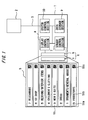
- a destination floor registration apparatus 1 has a touch-panel-type display device 6 for inputting a user operation, constituted by a display unit 5 using a sensor 4 and a display such as a dot-matrix LCD, a sensor control section 7 for controlling the sensor 4, a display control section 8 for displaying an image on the display unit 5, a data storage section 9 for storing images to be displayed, and a system control section 10 for controlling these components.
- a destination floor registration apparatus 1 is provided in a hall or car (only one is illustrated in the figure) and each destination floor registration apparatus 1 is connected to an elevator controller 2 via a communication line 3.
- the display unit 5 also functions as an operating unit having a button function for registering an elevator destination floor. Because the display unit 5 uses a dot-matrix-type display, it can display a two-dimensional code such as a QR code in which various sorts of information including service information are encoded.
- destination buttons 51 are rectangular frames displayed on the display unit 5 in order of floors. In each frame, an alphanumeric character 51a indicating a floor name, unique character information 51b representing the floor, and a two-dimensional code 51c in which service information corresponding to the floor is encoded are horizontally arranged in correspondence with the floor.
- a button function is provided to detect with the sensor 4 the position of one of the frames touched by an elevator user, and to thereby recognize the corresponding destination floor.
- the above-mentioned data storage section 9 can use, without any particular restriction, any of well-known storage elements or devices such as a hard disk drive, a nonvolatile memory, and a memory requiring write and hold operations at all times.
- the system control section 10 reads an image to be displayed from the data storage section 9 on the basis of data sent from the elevator controller 2, and sends the read image to the display control section 8 to display the image on the display unit 5.
- the destination floor registration apparatus 1 communicates the state of the destination button 51 to the elevator controller 2 through the communication line 3. When a destination floor is registered, the elevator controller 2 controls the elevator and notifies the destination floor registration apparatus 1 of the registered floor if necessary.
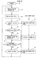
- the destination floor registration apparatus 1 starts operating by turning on or resetting a power supply not shown in the figures (step 1, startup).
- the system control section 10 receives button information from the elevator controller 2 (step S2, reception of button information), reads image data necessary for display from the data storage section 9 (step S3, read of display data), displays an initial view of the destination buttons 51 such as shown in Figure 1 (step S4, display of initial view) and enters a standby state such as to be able to accept an operating input from an elevator user.
- step S5 An operating input from the user is accepted in step S5 (step S5, operating input).
- step S6 When an operating input is given, the operating coordinates of the touched portion are sent to the system control section 10. Determination is made in the system control section 10 as to which destination button has been selected by the user. The determination result is transmitted from the system control section 10 to the elevator controller 2 (step S6, transmission of operating information). Determination is made as to whether or not there is a need for display (step S7, Need/non-need for display). If there is a need for a display update, the display on the display unit is updated by the display control section (step S8, display update).
- step S8 when the destination button 51 for the same floor as the floor on which the car not shown is landing is touched, it is determined that there is no need for display. In other cases, it is determined that there is a need for display, and the display of a portion corresponding to the touched destination button 51 is updated, for example, by a method of displaying in a highlighted state relative to other portions or a method comprising highlighting and simultaneously changing the display color. If the display is updated in the above-described step S8, the process returns to step S2, button information is received from the elevator controller 2 (step S2, reception of button information) and the same operation is subsequently repeated.
- a destination button 51 image including two-dimensional code 51c such as a QR code is displayed.
- the elevator user can read at all times the two-dimensional code 51c by a two-dimensional code reader function provided in a leader terminal 11 ( Figure 3) such as a portable telephone, as shown in a user operation A1 or A2 in Figure 2, and can display the read information at all times as shown in a user operation B.
- Figure 3 shows an example of display of floor information obtained about a restaurant on the seventh floor in a display view 11a on the reader terminal 11 in the possession of the user. The kind, name and outline of the restaurant placed on the seventh floor, an URL for access to the home page, a telephone number and other information items are displayed.
- Information to be displayed in two-dimensional code 51c can be contained as desired in the data storage section 9 by widely accepting in advance the provision of information from the building owner and tenants for example.
- the display unit 5 capable of displaying two-dimensional code 51c in which various sorts of information are encoded is combined with the operating unit having the button function to enable an elevator user to obtain a large amount of different sorts of information including floor information and tenant information almost instantly according to his/her preference by reading when necessary an image including two-dimensional code 51c displayed on the display unit 5 with a reader such as a portable telephone in the possession of the user, and to use the obtained information not only during rising/descending operation of the elevator but also after getting off the elevator for example, as well as to register a destination floor by operating the sensor 4 on the basis of the destination button 51 image displayed on the display unit 5, thus achieving an improvement in convenience.
- the user can read the obtained information and view information on a shop by accessing a designated URL during a waiting time before arrival of the elevator car or during elevator use to dissolve irritation during the waiting time and eliminate the time during which the user spends his/her time having nothing to do in the car.
- Figures 4 and 5 are diagrams for explaining an essential portion of a destination floor registration apparatus according to Embodiment 2 of this invention.
- Figure 4 is a diagram for explaining an example of display on the display unit.
- Figure 5 is a flowchart showing an example of the operation.
- image files with a two-dimensional code for providing other sorts of general service information are displayed by being changed at certain time intervals on the display unit 5 in the above-described Embodiment 1 in addition to the destination buttons 51.
- the display unit 5 constituting the destination floor registration apparatus 1 depicts a general service information display section 52 separately from eight destination buttons 51.
- the general service information display section 52 three images to be changed, formed of "bus schedule” 52A, "train schedule” 52B and "bargain information” 52C are prepared.
- the designated images (52A, 52B, 52C) are cyclically displayed one after another, one being replaced with another after a lapse of a designated time (e.g., five seconds).
- the general service information display section 52 is constituted by a title display section 52a for displaying a title of information and a two-dimensional code display section 52b for displaying information on contents corresponding to the title by encoding the information into a two-dimensional code.
- the two-dimensional code display section 52b is placed in the same position in the horizontal direction as that displayed position of the two-dimensional codes 51c in the destination floor registration buttons 51 so that the two-dimensional code display section 52b and the two-dimensional codes 51c are arranged in a line in the vertical direction.
- the configuration of Embodiment 2 is the same as that of Embodiment 1. The description of other details will not be repeated. A description will be made below by referring also to the configurational diagram of Figure 1.
- the display operation of the general service information display section 52 in Embodiment 2 arranged as described above will be described with reference to the flowchart of Figure 5.
- the destination floor registration apparatus 1 starts operating by turning on or resetting the power supply (step 11, startup)
- the destination floor registration button 51 image is displayed by the same procedure as that described above with reference to Figure 2.
- the system control section 10 reads a user setting file from the data storage section 9 to obtain the number of images to be selectively displayed, names of the files to be displayed and a display time (step S13).
- the system control section 10 reads data necessary for initial display from the data storage section 9 (step S 14, read of image to be displayed) and displays the information view on the general service information display section 52 on the display unit 5 (step S15, display of information view).
- step S15 determination is made as to the designated time (step S15, lapse of designated time).
- step S16 read of next image to be displayed
- step S17 display update
- a passenger who is on the elevator and who wishes to refer to a bus schedule for example reads the two-dimensional code displayed in "bus schedule" 52 with a reader terminal such as a portable telephone in his/her possession when "bus schedule" 52 is displayed in the general service information display section 52.
- the two-dimensional code is then decoded and the passenger can easily obtain the necessary information.
- various sorts of information e.g., building closing information, event information, bargain sale information, hot news in various fields such as politics, economy, society and sports can be provided as well as the above-mentioned information.
- FIG. 6 is a configurational diagram schematically showing an essential portion of a destination floor registration apparatus according to Embodiment 3 of this invention.
- the destination floor registration apparatus 1 has, in addition to the configuration of Embodiment 1 shown in Figure 1, a data receiving section 14 which is connected via a network 13 to a data input device 12 for inputting data such as an image file used for display externally supplied, and which receives data from the data input device 12.
- the configuration of Embodiment 3 is the same as that of Embodiment 1. The description of other details will not be repeated.
- the destination floor registration apparatus 1 communicates an image file used for display from the data input device 12 via the network 13.
- the data receiving section 14 stores the received image file in the data storage section 9. After reception of the image file, a read command is again received.
- the data receiving section 14 sends a command to the system control section 10 to redo reading images necessary for display from the data storage section 9 from the beginning.
- the system control section 10 reads the new image file and again displays the destination buttons 51.
- the apparatus is arranged to enable image files with two-dimensional codes to be updated via the network 13 and to thereby enable updating of information provided in a two-dimensional code without stopping the elevator, so that a person who maintains and manages the elevator can easily maintain the display contents.
- the data input device 12 may be arranged to use, for example, a personal computer or the like and to produce an image file to be displayed on the display unit 5 by inputting character information by means of the personal computer used as an input device and by encoding the necessary character information into a two-dimensional code.
- the destination buttons 51 for designating a destination floor are formed by using the touch-panel-type display device 6 and one unit is arranged to function both as an operating unit having a button function and as a unit for display of information in the form of two-dimensional code 51c.
- this invention is not limited to this arrangement.
- an operating unit having a button function may be separately provided, while the destination buttons themselves are arranged as an operating unit constituted by a well-known push-type button array.
- This operating unit may be provided by such a method that an ordinary dot-matrix LCD or the like is integrally provided by the side of the operating unit constituted by the destination buttons to display the character information 51b using characters and graphical symbols respectively related to floors and detailed service information using the two-dimensional code 51c.
- the destination floor registration apparatus in accordance with this invention is usable in a controller for a mechanical apparatus on which an ordinary user makes various settings and registrations.
Abstract
Description
- This invention relates to a destination floor registration apparatus provided in an elevator hall or an elevator car and, more particularly, to destination floor registration apparatus having the function of providing information such as service information including a two-dimensional code.
- As a conventional apparatus for displaying information in an elevator hall or an elevator car, an information display system for displaying various sorts of display data such as images, characters and broadcasts is known. Such a system provides an elevator user with various sorts of information by changing various sorts of display data on the basis of schedule data on time/time period settings or the like for display of various sorts of display data. For example, a system is known in which images, characters or the like prepared in advance are displayed to enable an elevator user to kill time or to obtain information on events in the building in which the elevator is installed (see, for example, patent document 1).
Another system is known in which a hall door is used as a screen and elevator operation information, etc., is projected onto the hall door by a projector mounted to a hall ceiling portion to provide information to a passenger waiting in the hall (see, for example, patent document 2). - Patent document 1:
Japanese Patent Laid-Open No. 9-34417
Patent document 2:Japanese Patent Laid-Open No. 9-263368 - Conventional apparatuses for displaying information as described above have problems that (1) because of a restricted display area it is not possible to give sufficient information to elevator users; (2) because displays are changed at certain time intervals, there is a possibility of missing a chance to view information which should be viewed, (3) in the case of scrolling display, there is a possibility of partially displaying information after a halfway point as well as a possibility for a viewer to get off the elevator before viewing the entire information; the completion of a message is not ensured.
- This invention has been achieved to solve problems of the conventional art such as those described above, and an object of this invention is to provide an elevator destination floor registration apparatus which provides information on elevator destination floors in the form of a two-dimensional code such as QR code to enable an elevator user to obtain guidance information with respect to each floor according to his/her need.
- To solve the above-described problems, this invention provides a destination floor registration apparatus including an operating unit having a button function for registering a destination floor for an elevator, a display unit combined with the operating unit and capable of displaying a two-dimensional code in which information is encoded, a display control section which controls display on the display unit, and a data storage section in which information for display on the display unit is stored.
- In this invention, the display unit capable of displaying a two-dimensional code in which information is encoded is combined with the operating unit having the button function for registering a destination floor to enable an elevator user to obtain a large amount of different sorts of information including floor information and tenant information almost instantly according to his/her preference with a two-dimensional reader provided in, for example, a portable telephone in the possession of the user, and to use the obtained information not only during rising/descending operation of the elevator but also after getting off the elevator for example, as well as to register a destination floor, thus achieving an improvement in convenience.
-
- Figure 1 is a configurational diagram schematically showing the overall configuration of a destination floor registration apparatus according to
Embodiment 1 of this invention; - Figure 2 is a flowchart showing an example of the operation of the destination floor registration apparatus shown in Figure 1;
- Figure 3 is a display screen diagram showing an example of the contents of information displayed on the destination floor registration apparatus shown in Figure 1 and transmitted to a two-dimensional code reader terminal;
- Figure 4 is a diagram for explaining an example of display on a display unit which is an essential portion of a destination floor registration apparatus according to
Embodiment 2 of the present invention; - Figure 5 is a flowchart showing an example of the operation of the destination floor registration apparatus shown in Figure 4; and
- Figure 6 is a configurational diagram schematically showing an essential portion of a destination floor registration apparatus according to
Embodiment 3 of this invention. -
- 1
- Destination floor registration apparatus
- 2
- Elevator controller
- 3
- Communication line
- 4
- Sensor
- 5
- Display unit (also functioning as operating unit)
- 6
- Touch-panel-type display device
- 7
- Sensor control section
- 8
- Display control section
- 9
- Data storage section
- 10
- System control section
- 11
- Reader terminal
- 11a
- Display view
- 12
- Data input device
- 13
- Network
- 14
- Data receiving section
- 51
- Destination button
- 51a
- Alphanumeric character
- 51b
- Character information
- 51c
- Two-dimensional code
- 52
- General service information display section
- 52A
- "Bus schedule"
- 52B
- "Train schedule"
- 52C
- "Bargain information"
- 52a
- Title display section
- 52b
- Two-dimensional code display section
- A destination floor registration apparatus of an elevator is explained by way of example in embodiments of this invention.
- Figures 1 to 3 are diagrams for explaining a destination floor registration apparatus according to
Embodiment 1 of this invention. Figure 1 is a configurational diagram schematically showing the overall configuration. Figure 2 is a flowchart showing an example of the operation. Figure 3 is a display screen diagram showing an example of the contents of information transmitted to a two-dimensional code reader terminal. Through the figures, the same reference characters indicate identical or corresponding portions. Referring to the figures, a destinationfloor registration apparatus 1 has a touch-panel-type display device 6 for inputting a user operation, constituted by adisplay unit 5 using asensor 4 and a display such as a dot-matrix LCD, asensor control section 7 for controlling thesensor 4, adisplay control section 8 for displaying an image on thedisplay unit 5, adata storage section 9 for storing images to be displayed, and asystem control section 10 for controlling these components. At least one destinationfloor registration apparatus 1 is provided in a hall or car (only one is illustrated in the figure) and each destinationfloor registration apparatus 1 is connected to anelevator controller 2 via acommunication line 3. - The
display unit 5 also functions as an operating unit having a button function for registering an elevator destination floor. Because thedisplay unit 5 uses a dot-matrix-type display, it can display a two-dimensional code such as a QR code in which various sorts of information including service information are encoded. InEmbodiment 1,destination buttons 51 are rectangular frames displayed on thedisplay unit 5 in order of floors. In each frame, analphanumeric character 51a indicating a floor name,unique character information 51b representing the floor, and a two-dimensional code 51c in which service information corresponding to the floor is encoded are horizontally arranged in correspondence with the floor. A button function is provided to detect with thesensor 4 the position of one of the frames touched by an elevator user, and to thereby recognize the corresponding destination floor. - The above-mentioned
data storage section 9 can use, without any particular restriction, any of well-known storage elements or devices such as a hard disk drive, a nonvolatile memory, and a memory requiring write and hold operations at all times. Thesystem control section 10 reads an image to be displayed from thedata storage section 9 on the basis of data sent from theelevator controller 2, and sends the read image to thedisplay control section 8 to display the image on thedisplay unit 5. The destinationfloor registration apparatus 1 communicates the state of thedestination button 51 to theelevator controller 2 through thecommunication line 3. When a destination floor is registered, theelevator controller 2 controls the elevator and notifies the destinationfloor registration apparatus 1 of the registered floor if necessary. - The operation of
Embodiment 1 arranged as described above will be described with reference to the flowchart shown in Figure 2. The destinationfloor registration apparatus 1 starts operating by turning on or resetting a power supply not shown in the figures (step 1, startup). Thesystem control section 10 receives button information from the elevator controller 2 (step S2, reception of button information), reads image data necessary for display from the data storage section 9 (step S3, read of display data), displays an initial view of thedestination buttons 51 such as shown in Figure 1 (step S4, display of initial view) and enters a standby state such as to be able to accept an operating input from an elevator user. - An operating input from the user is accepted in step S5 (step S5, operating input). When an operating input is given, the operating coordinates of the touched portion are sent to the
system control section 10. Determination is made in thesystem control section 10 as to which destination button has been selected by the user. The determination result is transmitted from thesystem control section 10 to the elevator controller 2 (step S6, transmission of operating information). Determination is made as to whether or not there is a need for display (step S7, Need/non-need for display). If there is a need for a display update, the display on the display unit is updated by the display control section (step S8, display update). - For example, when the
destination button 51 for the same floor as the floor on which the car not shown is landing is touched, it is determined that there is no need for display. In other cases, it is determined that there is a need for display, and the display of a portion corresponding to the toucheddestination button 51 is updated, for example, by a method of displaying in a highlighted state relative to other portions or a method comprising highlighting and simultaneously changing the display color. If the display is updated in the above-described step S8, the process returns to step S2, button information is received from the elevator controller 2 (step S2, reception of button information) and the same operation is subsequently repeated. - In the initial view illustrated in Figure 1 and in the view after a display update, a
destination button 51 image including two-dimensional code 51c such as a QR code is displayed. The elevator user can read at all times the two-dimensional code 51c by a two-dimensional code reader function provided in a leader terminal 11 (Figure 3) such as a portable telephone, as shown in a user operation A1 or A2 in Figure 2, and can display the read information at all times as shown in a user operation B. Figure 3 shows an example of display of floor information obtained about a restaurant on the seventh floor in adisplay view 11a on thereader terminal 11 in the possession of the user. The kind, name and outline of the restaurant placed on the seventh floor, an URL for access to the home page, a telephone number and other information items are displayed. Information to be displayed in two-dimensional code 51c can be contained as desired in thedata storage section 9 by widely accepting in advance the provision of information from the building owner and tenants for example. - According to
Embodiment 1, as described above, thedisplay unit 5 capable of displaying two-dimensional code 51c in which various sorts of information are encoded is combined with the operating unit having the button function to enable an elevator user to obtain a large amount of different sorts of information including floor information and tenant information almost instantly according to his/her preference by reading when necessary an image including two-dimensional code 51c displayed on thedisplay unit 5 with a reader such as a portable telephone in the possession of the user, and to use the obtained information not only during rising/descending operation of the elevator but also after getting off the elevator for example, as well as to register a destination floor by operating thesensor 4 on the basis of thedestination button 51 image displayed on thedisplay unit 5, thus achieving an improvement in convenience. Also, the user can read the obtained information and view information on a shop by accessing a designated URL during a waiting time before arrival of the elevator car or during elevator use to dissolve irritation during the waiting time and eliminate the time during which the user spends his/her time having nothing to do in the car. - Figures 4 and 5 are diagrams for explaining an essential portion of a destination floor registration apparatus according to
Embodiment 2 of this invention. Figure 4 is a diagram for explaining an example of display on the display unit. Figure 5 is a flowchart showing an example of the operation. InEmbodiment 2, image files with a two-dimensional code for providing other sorts of general service information are displayed by being changed at certain time intervals on thedisplay unit 5 in the above-describedEmbodiment 1 in addition to thedestination buttons 51. Referring to the figure, thedisplay unit 5 constituting the destinationfloor registration apparatus 1 depicts a general serviceinformation display section 52 separately from eightdestination buttons 51. In the general serviceinformation display section 52, three images to be changed, formed of "bus schedule" 52A, "train schedule" 52B and "bargain information" 52C are prepared. The designated images (52A, 52B, 52C) are cyclically displayed one after another, one being replaced with another after a lapse of a designated time (e.g., five seconds). - The general service
information display section 52 is constituted by atitle display section 52a for displaying a title of information and a two-dimensionalcode display section 52b for displaying information on contents corresponding to the title by encoding the information into a two-dimensional code. The two-dimensionalcode display section 52b is placed in the same position in the horizontal direction as that displayed position of the two-dimensional codes 51c in the destinationfloor registration buttons 51 so that the two-dimensionalcode display section 52b and the two-dimensional codes 51c are arranged in a line in the vertical direction. In other respects, the configuration ofEmbodiment 2 is the same as that ofEmbodiment 1. The description of other details will not be repeated. A description will be made below by referring also to the configurational diagram of Figure 1. - The display operation of the general service
information display section 52 inEmbodiment 2 arranged as described above will be described with reference to the flowchart of Figure 5. When the destinationfloor registration apparatus 1 starts operating by turning on or resetting the power supply (step 11, startup), the destinationfloor registration button 51 image is displayed by the same procedure as that described above with reference to Figure 2. Thesystem control section 10 reads a user setting file from thedata storage section 9 to obtain the number of images to be selectively displayed, names of the files to be displayed and a display time (step S13). Thesystem control section 10 reads data necessary for initial display from the data storage section 9 (stepS 14, read of image to be displayed) and displays the information view on the general serviceinformation display section 52 on the display unit 5 (step S15, display of information view). - Subsequently, determination is made as to the designated time (step S15, lapse of designated time). After a lapse of the designated time, the image to be displayed, designated next, is read (step S16, read of next image to be displayed) and a display update is made (step S17, display update). The destination registration operation is entirely the same as that in
Embodiment 1 and the description of it will not be repeated. - In
Embodiment 2 arranged as described above, a passenger who is on the elevator and who wishes to refer to a bus schedule for example reads the two-dimensional code displayed in "bus schedule" 52 with a reader terminal such as a portable telephone in his/her possession when "bus schedule" 52 is displayed in the general serviceinformation display section 52. The two-dimensional code is then decoded and the passenger can easily obtain the necessary information. As information displayed in the two-dimensional code, various sorts of information, e.g., building closing information, event information, bargain sale information, hot news in various fields such as politics, economy, society and sports can be provided as well as the above-mentioned information. - Figure 6 is a configurational diagram schematically showing an essential portion of a destination floor registration apparatus according to
Embodiment 3 of this invention. Referring to the figure, the destinationfloor registration apparatus 1 has, in addition to the configuration ofEmbodiment 1 shown in Figure 1, adata receiving section 14 which is connected via anetwork 13 to adata input device 12 for inputting data such as an image file used for display externally supplied, and which receives data from thedata input device 12. In other respects, the configuration ofEmbodiment 3 is the same as that ofEmbodiment 1. The description of other details will not be repeated. - In
Embodiment 3 arranged as described above, the destinationfloor registration apparatus 1 communicates an image file used for display from thedata input device 12 via thenetwork 13. Thedata receiving section 14 stores the received image file in thedata storage section 9. After reception of the image file, a read command is again received. Thedata receiving section 14 sends a command to thesystem control section 10 to redo reading images necessary for display from thedata storage section 9 from the beginning. Thesystem control section 10 reads the new image file and again displays thedestination buttons 51. - Thus, the apparatus is arranged to enable image files with two-dimensional codes to be updated via the
network 13 and to thereby enable updating of information provided in a two-dimensional code without stopping the elevator, so that a person who maintains and manages the elevator can easily maintain the display contents. Thedata input device 12 may be arranged to use, for example, a personal computer or the like and to produce an image file to be displayed on thedisplay unit 5 by inputting character information by means of the personal computer used as an input device and by encoding the necessary character information into a two-dimensional code. - In the above-described
Embodiments 1 to 3, thedestination buttons 51 for designating a destination floor are formed by using the touch-panel-type display device 6 and one unit is arranged to function both as an operating unit having a button function and as a unit for display of information in the form of two-dimensional code 51c. However, this invention is not limited to this arrangement. For example, an operating unit having a button function may be separately provided, while the destination buttons themselves are arranged as an operating unit constituted by a well-known push-type button array. This operating unit (not shown) may be provided by such a method that an ordinary dot-matrix LCD or the like is integrally provided by the side of the operating unit constituted by the destination buttons to display thecharacter information 51b using characters and graphical symbols respectively related to floors and detailed service information using the two-dimensional code 51c. - Needless to say, while the contents of a display on the
display unit 5 have been described as contents to be provided in a car, even a destination floor registration apparatus which is provided in a hall and which registers only an upper floor or a lower flower as a destination floor may be arranged in the same way and such an apparatus can have the same advantage. Also, while an example of an arrangement in which at least one destinationfloor registration apparatus 1 described above is provided in each hall or in each car, an arrangement may alternatively be adopted in which only the touch-panel-type display device 6 also functioning as an operating unit is provided in each hall or in each car while sections including thesensor control section 7, thedisplay control section 8, thedata storage section 9 and thesystem control sections 10 are controlled in a centralized manner in one unit. Needless to say, other various modifications and changes may be made within the scope of the spirit of this invention, for example, with respect to the display design of thedisplay unit 5 and the number of two-dimensional codes 51c to be displayed. - As described above, the destination floor registration apparatus in accordance with this invention is usable in a controller for a mechanical apparatus on which an ordinary user makes various settings and registrations.
Claims (7)
- A destination floor registration apparatus characterized by comprising an operating unit having a button function for registering a destination floor for an elevator, a display unit combined with the operating unit and capable of displaying a two-dimensional code in which information is encoded, a display control section which controls display on the display unit, and a data storage section in which information for display on the display unit is stored.
- The destination floor registration apparatus according to claim 1, characterized in that the display unit is constituted by a touch-panel-type display device and the touch-panel-type display device also functions as the operating unit having the button function.
- The destination floor registration apparatus according to claim 2, characterized in that the display unit displays destination buttons which are displayed in order of floors, and on each of which an alphanumeric character indicating a name of the corresponding one of the floors, unique character information about the floor and a two-dimensional code in which service information corresponding to the floor is encoded are horizontally arranged in correspondence with the floor.
- The destination floor registration apparatus according to any of claims 1 to 3, characterized in that the display unit has a general service information display section for displaying general service information about general services in and outside a building in which the elevator is installed and a two-dimensional code for detailed contents of the general service information.
- The destination floor registration apparatus according to claim 4, characterized in that in the general service information display section a plurality of groups of service information are selectively displayed one after another at predetermined time intervals.
- The destination floor registration apparatus according to any of claims 1 to 5, characterized in that the information in the two-dimensional code includes at least one of a URL and a telephone number.
- The destination floor registration apparatus according to any of claims 1 to 6, characterized in that the data storage section can be updated via a network.
Applications Claiming Priority (2)
| Application Number | Priority Date | Filing Date | Title |
|---|---|---|---|
| JP2005113363A JP2006290543A (en) | 2005-04-11 | 2005-04-11 | Destination floor registering device |
| PCT/JP2006/305040 WO2006109385A1 (en) | 2005-04-11 | 2006-03-14 | Destination floor registration device |
Publications (2)
| Publication Number | Publication Date |
|---|---|
| EP1870367A1 true EP1870367A1 (en) | 2007-12-26 |
| EP1870367A4 EP1870367A4 (en) | 2013-01-09 |
Family
ID=37086678
Family Applications (1)
| Application Number | Title | Priority Date | Filing Date |
|---|---|---|---|
| EP06729074A Withdrawn EP1870367A4 (en) | 2005-04-11 | 2006-03-14 | Destination floor registration device |
Country Status (5)
| Country | Link |
|---|---|
| EP (1) | EP1870367A4 (en) |
| JP (1) | JP2006290543A (en) |
| KR (1) | KR20070067205A (en) |
| CN (1) | CN100569618C (en) |
| WO (1) | WO2006109385A1 (en) |
Cited By (7)
| Publication number | Priority date | Publication date | Assignee | Title |
|---|---|---|---|---|
| WO2016042200A1 (en) * | 2014-09-19 | 2016-03-24 | Kone Corporation | Display language arrangement |
| CN105540368A (en) * | 2016-02-01 | 2016-05-04 | 上海新时达电气股份有限公司 | Elevator button and elevator |
| WO2016207478A1 (en) * | 2015-06-26 | 2016-12-29 | Kone Corporation | Content information of floor of elevator |
| WO2017005828A1 (en) * | 2015-07-08 | 2017-01-12 | Inventio Ag | Operating panel for an elevator providing options of indicating additional floor information |
| EP3483104A1 (en) * | 2017-11-10 | 2019-05-15 | Otis Elevator Company | Systems and methods for providing information regarding elevator systems |
| US11332340B2 (en) | 2018-08-28 | 2022-05-17 | Tk Elevator Innovation And Operations Gmbh | Elevator control and user interface system |
| WO2022253510A1 (en) * | 2021-05-31 | 2022-12-08 | Inventio Ag | Elevator operating device for an elevator installation with destination call control |
Families Citing this family (19)
| Publication number | Priority date | Publication date | Assignee | Title |
|---|---|---|---|---|
| JP2010006551A (en) * | 2008-06-27 | 2010-01-14 | Toshiba Elevator Co Ltd | Elevator control device |
| KR101233933B1 (en) * | 2008-10-21 | 2013-02-15 | 미쓰비시덴키 가부시키가이샤 | Elevator system |
| CN102482051B (en) * | 2009-08-28 | 2014-12-10 | 三菱电机株式会社 | Elevator operating panel |
| JP2011255982A (en) * | 2010-06-07 | 2011-12-22 | Hitachi Ltd | Informing notifying device of elevator |
| KR101314065B1 (en) * | 2011-12-08 | 2013-10-07 | 현대엘리베이터주식회사 | Destination selecting system of elevator and the control method thereof |
| JP2013159471A (en) * | 2012-02-08 | 2013-08-19 | Hitachi Ltd | Secret operation elevator |
| CN103373650B (en) * | 2012-04-11 | 2016-03-09 | 上海智显光电科技有限公司 | There is the elevator control dial of information inquiry Presentation Function |
| CN105197700A (en) * | 2014-06-05 | 2015-12-30 | 三菱电机上海机电电梯有限公司 | Visitor system taking two-dimensional code as medium for elevator and control method thereof |
| CN105173933B (en) * | 2015-10-12 | 2017-10-31 | 广州广日电梯工业有限公司 | By recognizing that ciphering two-dimension code calls the control system and method for ladder together |
| JP6315150B2 (en) * | 2016-02-29 | 2018-04-25 | フジテック株式会社 | Information providing device, elevator group management system, and elevator system |
| US9878875B1 (en) * | 2016-09-30 | 2018-01-30 | Otis Elevator Company | Building selection in elevator system supporting mobile device calls |
| CN106904502B (en) * | 2017-04-21 | 2019-01-01 | 北京梦想加科技有限公司 | A kind of control method of the terraced control system of intelligence based on two dimensional code barcode scanning |
| JP6447794B1 (en) * | 2017-10-06 | 2019-01-09 | 三菱電機株式会社 | elevator |
| CN108408513A (en) * | 2018-03-19 | 2018-08-17 | 深圳市敢为特种设备物联网技术有限公司 | Elevator Quick Response Code boarding control method, device and computer readable storage medium |
| CN110626897B (en) * | 2018-06-25 | 2021-10-08 | 上海三菱电梯有限公司 | Touch screen device and elevator operating system |
| AU2019373294B2 (en) * | 2018-10-30 | 2023-03-30 | Inventio Ag | Lift operation terminal having situation-specific floor display |
| CN109368425B (en) * | 2018-12-26 | 2020-10-16 | 福州快科电梯工业有限公司 | Space three-dimensional interactive elevator calling system based on mobile terminal and working method |
| CN109969876A (en) * | 2019-04-23 | 2019-07-05 | 上海三菱电梯有限公司 | A kind of elevator floor calling mechanism |
| CN111792463A (en) * | 2020-06-01 | 2020-10-20 | 北京清大视觉科技有限公司 | Non-contact elevator control method and system and elevator |
Citations (3)
| Publication number | Priority date | Publication date | Assignee | Title |
|---|---|---|---|---|
| US5726435A (en) * | 1994-03-14 | 1998-03-10 | Nippondenso Co., Ltd. | Optically readable two-dimensional code and method and apparatus using the same |
| JP2001265800A (en) * | 2000-03-16 | 2001-09-28 | Laurel Intelligent Systems Co Ltd | Transaction information processing system for article/ service using two-dimensional code |
| EP1291311A1 (en) * | 2000-06-16 | 2003-03-12 | Mitsubishi Denki Kabushiki Kaisha | Operating board for elevator |
Family Cites Families (3)
| Publication number | Priority date | Publication date | Assignee | Title |
|---|---|---|---|---|
| JP2001226051A (en) * | 2000-02-14 | 2001-08-21 | Hitachi Building Systems Co Ltd | Information display device for elevator |
| JP2005208148A (en) * | 2004-01-20 | 2005-08-04 | Mitsubishi Electric Corp | Information display system |
| JP2006124140A (en) * | 2004-11-01 | 2006-05-18 | Toshiba Elevator Co Ltd | Information display system for elevator |
-
2005
- 2005-04-11 JP JP2005113363A patent/JP2006290543A/en active Pending
-
2006
- 2006-03-14 EP EP06729074A patent/EP1870367A4/en not_active Withdrawn
- 2006-03-14 WO PCT/JP2006/305040 patent/WO2006109385A1/en active Application Filing
- 2006-03-14 CN CNB2006800010736A patent/CN100569618C/en not_active Expired - Fee Related
- 2006-03-14 KR KR1020077010807A patent/KR20070067205A/en not_active Application Discontinuation
Patent Citations (3)
| Publication number | Priority date | Publication date | Assignee | Title |
|---|---|---|---|---|
| US5726435A (en) * | 1994-03-14 | 1998-03-10 | Nippondenso Co., Ltd. | Optically readable two-dimensional code and method and apparatus using the same |
| JP2001265800A (en) * | 2000-03-16 | 2001-09-28 | Laurel Intelligent Systems Co Ltd | Transaction information processing system for article/ service using two-dimensional code |
| EP1291311A1 (en) * | 2000-06-16 | 2003-03-12 | Mitsubishi Denki Kabushiki Kaisha | Operating board for elevator |
Non-Patent Citations (1)
| Title |
|---|
| See also references of WO2006109385A1 * |
Cited By (15)
| Publication number | Priority date | Publication date | Assignee | Title |
|---|---|---|---|---|
| US10427910B2 (en) | 2014-09-19 | 2019-10-01 | Kone Corporation | Display language arrangement |
| WO2016042200A1 (en) * | 2014-09-19 | 2016-03-24 | Kone Corporation | Display language arrangement |
| US11661310B2 (en) | 2015-06-26 | 2023-05-30 | Kone Corporation | Content information of floor of elevator |
| WO2016207478A1 (en) * | 2015-06-26 | 2016-12-29 | Kone Corporation | Content information of floor of elevator |
| CN107735348B (en) * | 2015-07-08 | 2020-02-14 | 因温特奥股份公司 | Elevator operating panel for providing options to indicate additional floor information |
| AU2016290578B2 (en) * | 2015-07-08 | 2019-06-20 | Inventio Ag | Operating panel for an elevator providing options of indicating additional floor information |
| CN107735348A (en) * | 2015-07-08 | 2018-02-23 | 因温特奥股份公司 | For providing the lift operation panel for the option for indicating additional floor information |
| WO2017005828A1 (en) * | 2015-07-08 | 2017-01-12 | Inventio Ag | Operating panel for an elevator providing options of indicating additional floor information |
| US11192749B2 (en) | 2015-07-08 | 2021-12-07 | Inventio Ag | Operating panel for an elevator providing options of indicating additional floor information |
| CN105540368A (en) * | 2016-02-01 | 2016-05-04 | 上海新时达电气股份有限公司 | Elevator button and elevator |
| EP3483104A1 (en) * | 2017-11-10 | 2019-05-15 | Otis Elevator Company | Systems and methods for providing information regarding elevator systems |
| CN109867179A (en) * | 2017-11-10 | 2019-06-11 | 奥的斯电梯公司 | For providing the system and method for the information about elevator device |
| US11247869B2 (en) | 2017-11-10 | 2022-02-15 | Otis Elevator Company | Systems and methods for providing information regarding elevator systems |
| US11332340B2 (en) | 2018-08-28 | 2022-05-17 | Tk Elevator Innovation And Operations Gmbh | Elevator control and user interface system |
| WO2022253510A1 (en) * | 2021-05-31 | 2022-12-08 | Inventio Ag | Elevator operating device for an elevator installation with destination call control |
Also Published As
| Publication number | Publication date |
|---|---|
| EP1870367A4 (en) | 2013-01-09 |
| JP2006290543A (en) | 2006-10-26 |
| KR20070067205A (en) | 2007-06-27 |
| CN101052582A (en) | 2007-10-10 |
| CN100569618C (en) | 2009-12-16 |
| WO2006109385A1 (en) | 2006-10-19 |
Similar Documents
| Publication | Publication Date | Title |
|---|---|---|
| EP1870367A1 (en) | Destination floor registration device | |
| US6529786B1 (en) | Queue management system | |
| KR100375054B1 (en) | Display device and its operation method | |
| EP1764334A1 (en) | Elevator call registration system | |
| EP3309722A1 (en) | Waitlist management system, waitlist management device, and waitlist management program | |
| EP3067852A1 (en) | Order management system, order management method, and program | |
| WO2009009100A1 (en) | Automatic guidance of visitor in new facility through access control system integration with lcd display | |
| WO2017170855A1 (en) | Queue management system, management server, and program | |
| EP2665021A1 (en) | Queuing system | |
| US20180174077A1 (en) | Turn Management System and Recording Medium Having Turn Management Program Recorded Thereon | |
| JP5102482B2 (en) | Elevator advertisement display management system | |
| JP5444768B2 (en) | Information recommendation device, server, method and program | |
| US7159179B2 (en) | Service providing system and service providing device that provides a specific service in response to user authority determination based on positional relationships of virtual objects | |
| US20010040533A1 (en) | Shop information advertisement panel system and shop information advertisement method | |
| JP2001317958A (en) | Method and system for specifying present position in event site | |
| JP2008250595A (en) | Display terminal device, terminal device for store installation, information display system and information display method | |
| KR102243576B1 (en) | AR based guide service for exhibition | |
| EP1191507A2 (en) | Display stand incorporating an internet server | |
| JP2005157451A (en) | Numbered ticket issuing device and acceptance numbered ticket using system | |
| US20230045055A1 (en) | Information input system | |
| US20230359159A1 (en) | Control system and method for displaying dedicated content related to a building | |
| JP7070640B1 (en) | Control device and destination floor registration device | |
| JP2000194781A (en) | Vacant seat managing device | |
| JP2008040919A (en) | Positional information display system | |
| JP4803427B2 (en) | Photo printing system |
Legal Events
| Date | Code | Title | Description |
|---|---|---|---|
| PUAI | Public reference made under article 153(3) epc to a published international application that has entered the european phase |
Free format text: ORIGINAL CODE: 0009012 |
|
| 17P | Request for examination filed |
Effective date: 20070413 |
|
| AK | Designated contracting states |
Kind code of ref document: A1 Designated state(s): DE |
|
| DAX | Request for extension of the european patent (deleted) | ||
| RBV | Designated contracting states (corrected) |
Designated state(s): DE |
|
| A4 | Supplementary search report drawn up and despatched |
Effective date: 20121207 |
|
| RIC1 | Information provided on ipc code assigned before grant |
Ipc: B66B 1/14 20060101ALI20121203BHEP Ipc: B66B 1/46 20060101ALI20121203BHEP Ipc: B66B 3/00 20060101AFI20121203BHEP |
|
| STAA | Information on the status of an ep patent application or granted ep patent |
Free format text: STATUS: THE APPLICATION IS DEEMED TO BE WITHDRAWN |
|
| 18D | Application deemed to be withdrawn |
Effective date: 20130713 |