EP1878618A2 - Driving support method and apparatus - Google Patents
Driving support method and apparatus Download PDFInfo
- Publication number
- EP1878618A2 EP1878618A2 EP07013028A EP07013028A EP1878618A2 EP 1878618 A2 EP1878618 A2 EP 1878618A2 EP 07013028 A EP07013028 A EP 07013028A EP 07013028 A EP07013028 A EP 07013028A EP 1878618 A2 EP1878618 A2 EP 1878618A2
- Authority
- EP
- European Patent Office
- Prior art keywords
- driver
- image
- vehicle
- pillar
- camera
- Prior art date
- Legal status (The legal status is an assumption and is not a legal conclusion. Google has not performed a legal analysis and makes no representation as to the accuracy of the status listed.)
- Granted
Links
- 238000000034 method Methods 0.000 title claims description 16
- 238000003384 imaging method Methods 0.000 claims description 57
- 210000003128 head Anatomy 0.000 description 75
- 238000010586 diagram Methods 0.000 description 18
- 238000013459 approach Methods 0.000 description 11
- 238000013500 data storage Methods 0.000 description 4
- 238000001514 detection method Methods 0.000 description 3
- 230000003287 optical effect Effects 0.000 description 3
- 210000000887 face Anatomy 0.000 description 2
- 102220124522 rs746215581 Human genes 0.000 description 2
- 230000037237 body shape Effects 0.000 description 1
- 238000004364 calculation method Methods 0.000 description 1
- 238000006243 chemical reaction Methods 0.000 description 1
- 238000004519 manufacturing process Methods 0.000 description 1
- 230000000873 masking effect Effects 0.000 description 1
- 230000000007 visual effect Effects 0.000 description 1
Images


Classifications
-
- B—PERFORMING OPERATIONS; TRANSPORTING
- B60—VEHICLES IN GENERAL
- B60R—VEHICLES, VEHICLE FITTINGS, OR VEHICLE PARTS, NOT OTHERWISE PROVIDED FOR
- B60R1/00—Optical viewing arrangements; Real-time viewing arrangements for drivers or passengers using optical image capturing systems, e.g. cameras or video systems specially adapted for use in or on vehicles
- B60R1/20—Real-time viewing arrangements for drivers or passengers using optical image capturing systems, e.g. cameras or video systems specially adapted for use in or on vehicles
- B60R1/22—Real-time viewing arrangements for drivers or passengers using optical image capturing systems, e.g. cameras or video systems specially adapted for use in or on vehicles for viewing an area outside the vehicle, e.g. the exterior of the vehicle
- B60R1/23—Real-time viewing arrangements for drivers or passengers using optical image capturing systems, e.g. cameras or video systems specially adapted for use in or on vehicles for viewing an area outside the vehicle, e.g. the exterior of the vehicle with a predetermined field of view
- B60R1/25—Real-time viewing arrangements for drivers or passengers using optical image capturing systems, e.g. cameras or video systems specially adapted for use in or on vehicles for viewing an area outside the vehicle, e.g. the exterior of the vehicle with a predetermined field of view to the sides of the vehicle
-
- B—PERFORMING OPERATIONS; TRANSPORTING
- B60—VEHICLES IN GENERAL
- B60Q—ARRANGEMENT OF SIGNALLING OR LIGHTING DEVICES, THE MOUNTING OR SUPPORTING THEREOF OR CIRCUITS THEREFOR, FOR VEHICLES IN GENERAL
- B60Q9/00—Arrangement or adaptation of signal devices not provided for in one of main groups B60Q1/00 - B60Q7/00, e.g. haptic signalling
- B60Q9/008—Arrangement or adaptation of signal devices not provided for in one of main groups B60Q1/00 - B60Q7/00, e.g. haptic signalling for anti-collision purposes
-
- B—PERFORMING OPERATIONS; TRANSPORTING
- B60—VEHICLES IN GENERAL
- B60R—VEHICLES, VEHICLE FITTINGS, OR VEHICLE PARTS, NOT OTHERWISE PROVIDED FOR
- B60R2300/00—Details of viewing arrangements using cameras and displays, specially adapted for use in a vehicle
- B60R2300/20—Details of viewing arrangements using cameras and displays, specially adapted for use in a vehicle characterised by the type of display used
- B60R2300/202—Details of viewing arrangements using cameras and displays, specially adapted for use in a vehicle characterised by the type of display used displaying a blind spot scene on the vehicle part responsible for the blind spot
Definitions
- the present invention relates to a driving support method and apparatus.
- an in-vehicle system for capturing an image of area which is hidden as a blind spot of a driver of the vehicle with an in-vehicle camera and displaying the image on a display monitor.
- a system that captures an image of area which is hidden as a blind spot of a driver of a vehicle arising because of a presence of a front pillar in the vehicle with an in-vehicle camera and displays the image on an inner (medial) side of the front pillar has been suggested.
- the front pillar is located to each of the right and left front of the driver to support the front window and the roof of the vehicle and obstructs the driver's view.
- the front pillar needs to have a certain thickness to ensure the safety of the driver.
- the system described above includes an in-vehicle camera, an image processor for processing an image signal which is output from the in-vehicle camera, a display which is attached on the inner side of the front pillar for displaying the image, and a projector for projecting the image on the inner surface of the front pillar.
- the driver may have a front view as if the front pillar were transparent and it may be possible for the driver to recognize a road shape and/or an obstacle in front side of the vehicle at an intersection that otherwise would not be possible.
- An apparatus disclosed in Japanese Unexamined Patent Application Publication No. 2005-184225 captures images of areas surrounding a vehicle by in-vehicle cameras, the cameras being individually attached at right and left side mirrors, and projects the images on medial surfaces of front pillars of the vehicle.
- the apparatus further detects coordinates of eyes of a driver of the vehicle and corrects the images provided by the cameras on the basis of the positions of the eyes of the driver.
- each image is generated on the basis of one camera, so that the generated image has a limited view area even if the apparatus detects the coordinates of the eyes of the driver and corrects the image on the basis of the coordinates. More specifically, for example, in case of a vehicle with righthand drive, the driver seated on the driver seat of the vehicle may see an obstacle located to the front and right of the vehicle if the driver leans forward to and peers at the area to the front and right of the vehicle through the front window. However, the driver may not see the obstacle while the driver has his/her back against the back of the seat (hereinafter, this position is referred to as "standard posture").
- various exemplary implementations of the principles described herein provide a driving support method for capturing an image of area which is hidden as a blind spot of a driver of a vehicle arising because of a presence of a pillar of the vehicle using an imaging device which is attached on the vehicle and displaying the image provided by the imaging device on an inner side of the pillar, comprising: detecting a position of the driver who is seated on a driver's seat of the vehicle; selecting one of the imaging devices to capture an image among a plurality of the imaging devices which capture images of different areas in accordance with the position of the driver; and displaying an image on the inner side of the pillar on the basis of an image signal input from the selected imaging device.
- a driving support apparatus for capturing an image of area which is hidden as a blind spot of a driver of a vehicle arising because of a presence of a pillar of the vehicle using an imaging device mounted on the vehicle and displaying the image provided by the imaging device on an inner side of the pillar, comprising: a detecting device for detecting a position of the driver who is seated on a driver's seat in the vehicle; a selecting device for selecting one of the imaging devices among a plurality of the imaging devices which capture images of different areas in accordance with the position of the driver; an image signal obtaining device for inputting an image signal from the selected imaging device; and an output control device for displaying an image of area which is hidden as a blind spot of the driver of the vehicle arising because of the presence of the pillar on the inner side of the pillar in the vehicle on the basis of the image signal which is input from the imaging device.
- a driving support apparatus for capturing an image of area which is hidden as a blind spot of a driver of a vehicle arising because of a presence of a pillar of the vehicle using an imaging device mounted on the vehicle and displaying the image which is provided by the imaging device on an inner side of the pillar, comprising: a detecting device for detecting a position of the driver who is seated on a driver's seat in the vehicle; an angle calculating device for calculating an angle of the blind spot arising caused by the presence of the pillar on the basis of the position of the driver detected by the detecting device; a selecting device for selecting one of the imaging devices among a plurality of the imaging devices which capture images of different areas in accordance with the blind spot angle for the driver; an image signal obtaining device for inputting an image signal from the selected imaging device; and an output control device for displaying an image of the blind spot of the driver arising because of the presence of the pillar on the inner side of the pillar in the vehicle on
- the selecting device selects, provided that a maximum angle of the blind spot angle arising because of the presence of the pillar in a vehicle width direction is less than predetermined numbers of degrees relative to a horizontal axis, first imaging device to capture an image which mainly includes area in front of the vehicle, or selects, provided that the maximum angle is equal to or greater than the predetermined numbers of degrees, second imaging device to capture an image which mainly includes area in front of the vehicle.
- the driving support apparatus further comprising: an image processing device for performing image processing on an image signal input from the imaging device in accordance with the position of the driver.
- the position of the driver is detected and one imaging device is selected among a plurality of the imaging devices in accordance with the position of the driver.
- the image provided by the selected imaging device is displayed on the inner side of the pillar. Therefore, even if the driver changes his/her posture, an appropriate imaging device may be selected according to the position of the driver and the image displayed on the pillar may be smoothly connected with the real view from, for example, the front window when viewed from the driver.
- the driving support apparatus detects the position of the driver and selects one imaging device among a plurality of the imaging devices in accordance with the position of the driver. Then the image provided by the selected imaging device is displayed on the inner side of the pillar. Therefore, even if the driver changes his/her posture, an appropriate imaging device may be selected according to the position of the driver and the image displayed on the pillar may be smoothly connected with the real view from, for example, the front window when viewed from the driver.
- the driving support apparatus detects the position of the driver and calculates the blind spot angle arising because of the presence of the pillar in accordance with the position of the driver. Then an appropriate imaging device is selected according to the blind spot angle and the image provided by the selected imaging device is displayed on the inner side of the pillar. Therefore, even if the driver changes his/her posture, an appropriate imaging device may be selected according to the position of the driver and the image displayed on the pillar may be smoothly connected with the real view from, for example, the front window when viewed from the driver.
- the first imaging device which captures an image mainly including the front side area of the vehicle is selected.
- the second imaging device which captures an image mainly including the area in front of the vehicle is selected. That is, when the blind spot angle faces about right/left forward, the first imaging device which captures the image mainly including the front side area of the vehicle is selected and when the blind spot angle faces forward, the second imaging device which captures the image mainly including the area in front of the vehicle is selected. Therefore, even if the driver changes his/her posture, an appropriate imaging device may be selected according to the position of the driver and the image displayed on the pillar may be smoothly connected with the real view from, for example, the front window when viewed from the driver.
- the detecting device detects coordinates of the head of the driver, so that it may be relatively possible to specify the accurate posture of the driver.
- the image displayed on the pillar may connect with the real view when viewed from the driver.
- FIG. 1 is a block diagram showing a driving support system of a current embodiment.
- FIG. 2 is a diagram showing a range of a first camera.
- FIG. 3 is a diagram showing a range of a second camera.
- FIG. 4 is a diagram showing positions of a projector and a pillar.
- FIG. 5 is a diagram showing an inner side view of the pillar.
- FIG. 6 is a diagram showing a mask pattern.
- FIG. 7 is a diagram showing a side view of a sensor.
- FIG. 8 is a diagram showing an upper side view of the sensor.
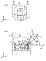
- FIG. 9 is a diagram showing a horizontal blind spot of a driver when the driver's head leans to forward and to right.
- FIG. 10 is a diagram showing a vertical blind spot of the driver when the driver's head leans to forward and to right.
- FIG. 11 is a diagram showing a horizontal blind spot of the driver when the driver's head leans to backward and to right.
- FIG. 12 is a diagram showing a vertical blind spot of the driver when the driver's head leans to backward and to right.
- FIG. 13 is a diagram showing a horizontal blind spot of the driver when the driver's head leans to forward and to left.
- FIG. 14 is a diagram showing a horizontal blind spot of the driver when the driver's head leans to backward and to left.
- FIG. 15 is a diagram showing procedures in the current embodiment.
- FIG. 16 is a diagram showing an image projected on the pillar.
- FIG. 17 is a diagram showing an image projected on the pillar.
- FIG. 1 is a block diagram showing a structure of a driving support system 1 installed in a vehicle.
- the driving support system 1 is installed in a vehicle C (in FIG. 2) and may include a driving support unit 2 as a driving support device, a display 3 as a display device, a projector 4, a speaker 5, a first camera 6 and a second camera 7 as imaging devices, and first through third position detecting sensors 8a through 8c.
- the driving support unit 2 may include a control section 10 as a detecting device, a selecting device, and an angle calculating device, a nonvolatile main memory 11, a ROM 12, and a GPS receiver 13.
- the control section 10 is, for example, a CPU, an MPU, or an ASIC, and mainly controls various processing operations on the basis of a driving support program stored in the ROM 12.
- the main memory 11 temporarily stores a calculation result output by the control section 10.
- the control section 10 inputs a position detection signal indicating coordinates such as latitude/longitude, which is generated by a GPS satellite and received by the GPS receiver 13, and calculates an absolute position of the vehicle in which the driving support system is installed by means of electronic navigation.
- the control section 10 further inputs a vehicle speed pulse and an angular velocity calculated by a vehicle speed sensor 30 and a gyro 31, both of which are attached on the vehicle, through a vehicle I/F section 14 of the driving support unit 2.
- the control section 10 calculates a relative position on the basis of an origin position by means of autonomous navigation using the vehicle speed pulse and the angular velocity and specifies the current vehicle position on the basis of the relative position calculated by autonomous navigation and the absolute position calculated by electronic navigation.
- the driving support unit 2 may include a geographic data storage section 15.
- the geographic data storage section 15 is an internal hard disk or an external storage device such as an optical disk.
- route data 16 route network data as map data for searching for a route to a destination
- map drawing data 17 for outputting a map screen 3a on the display 3 are stored.
- the route data 16 is data regarding roads within areas divided into a mesh grid according to a national map.
- the route data 16 may include, for example, a mesh ID as an identifier of each mesh, a link ID as an identifier of each link in the mesh, and a link cost.
- the control section 10 searches for a recommended route to a destination using route data 16 and determines whether the vehicle C approaches a point for which guidance is to be given such as an intersection.
- each road may consist of a plurality of componential units called links.
- Each link may be separated and defined by, for example, an intersection, an intersection having more than three roads, a curve, a highway entry point, and/or a point at which the road type changes.
- the map drawing data 17 is data used when a road shape and/or a view from the driver is drawn and stored by each mesh which a map is divided into according to the national map.
- the control section 10 determines whether there is a curve whose curvature is equal to or greater than a predetermined value in front of the vehicle C on the basis of road shape data included in the map drawing data 17.
- the driving support unit 2 may include a map drawing processor 18.
- the map drawing processor 18 reads out the map drawing data 17 from the map data storage section 15 to draw a map of an area surrounding the vehicle C.
- the map drawing processor 18 further generates data for outputting the map and temporarily stores the data in a VRAM (not shown).
- the map drawing processor 18 outputs image signals on the basis of the generated data for outputting the map on the display 3 and displays a map screen 3a as shown in FIG. 1.
- the map drawing processor 18 further overlaps a vehicle position indicator 3b indicating the position of the vehicle C on the map screen 3a.
- the driving support unit 2 may include an audio processor 24.
- the audio processor 24 has an audio file (not shown) and outputs, for example, audio guidance for the route to the destination from the speaker 5.
- the driving support unit 2 may further include an external input I/F section 25.
- the external input I/F section 25 inputs an input signal which is generated by input of an operation switch 26 located next to the display 3 and/or the display 3 which is a touch panel operated by a user and outputs the signal to the control section 10.
- the driving support unit 2 may further include an image data input section 22 as an image signal obtaining device and an image processor 20 for inputting image data G from the image data input section 22 as an output control device and an image processing device.
- the image data input section 22 activates the first camera 6 or the second camera 7, both of which are attached on the vehicle C, and inputs an image signal M provided by the first camera 6 or the second camera 7 in a controlled environment by the control section 10.
- the first camera 6 is a color digital camera which has an optical system including a lens (not shown), a mirror, etc. and a CCD image sensor (not shown). As shown in FIG. 2, the first camera 6 is attached on an outer lower side of a right front pillar of the vehicle C (hereinafter referred to as pillar P) and whose optical axis points to an area to the front and right of the vehicle C. According to the current embodiment, the vehicle C is righthand drive, so that the first camera 6 is attached on the right side (the driver seat side) of the vehicle C. The first camera 6 takes a picture of a region Z1 which includes the area to the front and right of the vehicle C and a part of the right side body of the vehicle C.
- the second camera 7 has the same structure as the first camera 6. As shown in FIG. 3, the second camera 7 is attached on the outer upper side of the pillar P. More specifically, the first camera 6 and the second camera 7 are attached on the both ends of the pillar P, which is inclined, so that the positions of the two cameras are different from each other in any direction which is a vehicle length direction parallel to a shaft of the vehicle C (X-direction in FIG. 3), a vehicle width direction (Y-direction in FIG. 3) or a vertical direction (Z-direction in FIG 3).
- the second camera 7 is located behind the first camera 6 in the length direction (X-direction) and takes a picture of a region Z2 which is mainly the area in front of the vehicle C.
- the first camera 6 takes a picture of an area positioned further to the right of the vehicle C than the second camera 7 does.
- an obstacle which is located to the front and right of the vehicle C may be easier to enter the range of the first camera 6 than the range of the second camera 7.
- the image signal M provided by the first camera 6 or the second camera 7 is digitalized and converted into image data G by the image data input section 22.
- the image data G is output to the image processor 20.
- the image processor 20 processes image data G and outputs the processed image data G on the projector 4.
- the projector 4 is attached on the inner side of a roof R and in the upper side direction of a front seat F on which a driver D is seated.
- the projector 4 may project an image on the surface of the right pillar P of the vehicle C (FIG. 5).
- a screen SC which is cut in accordance with the shape of the pillar P is attached on the inner side Pa of the pillar P.
- the focus of the projector 4 is adjusted for the screen SC. Note that, if a projected light may be received and a clear image may be displayed directly on the inner side Pa of the pillar P in accordance with the material and the shape of the inner side Pa, the screen SC may not be used.
- a mask pattern 40 and pillar shape data 41 are stored in the ROM 12 of the driving support unit 2 in advance during the process for manufacturing the unit.
- the mask pattern 40 is data for masking image data G and includes an image display section 40a whose shape extends along the shape of the inner side of the pillar P and a mask 40b.
- the image processor 20 uses pixel data of image data G which is provided by the first camera 6 or the second camera 7 for generating output data OD for the image display section 40a.
- the image processor 20 uses pixel data provided by the projector 4 but not for displaying and generates output data OD.
- the image processor 20 outputs two of the output data OD to the projector 4. As a result, an image is projected only on the screen SC on the pillar P. Any image is not projected on the other area surrounding the screen SC such as the front window W1 or the door window W2 because of the mask 40b.
- Pillar shape data 41 is data including a pattern or coordinates according to the outline of the pillar and each vehicle C has own data.
- the control section 10 may obtain 3D coordinates (X, Y, Z), which are the length direction, the vehicle width direction, and the vertical direction, of the outline of the pillar P on the basis of pillar shape data 41. Further, the control section 10 may obtain 3D coordinate data of the width and/or the length of the pillar P.
- the driving support unit 2 may include a sensor I/F section 23 as a detecting device.
- the sensor I/F section 23 inputs detecting signals from the first through third position detecting sensors 8a through 8c.
- the first through third position detecting sensors 8a through 8c are ultrasonic sensors and are attached in the vehicle C, especially the area surrounding the driver D being seated on the front seat F.
- the first position detecting sensor 8a is attached near a room mirror (front mirror) RM and at about equal level to or a little higher level of a head D1 of the driver D.
- the second position detecting sensor 8b is attached on the upper side of the door window W2 (FIG. 5) and that is the upper right of the driver D. According to the current embodiment, the second position detecting sensor 8b is located at about the same level of the first position detecting sensor 8a on the length direction (X-direction).
- the third position detecting sensor 8c is embedded with a head rest FH of the front seat F.
- the third position detecting sensor 8c is located lower than the first and second position detecting sensors 8a and 8b on the vertical direction (Z-direction). Further, as shown in FIG. 8, the third position detecting sensor 8c is located between the first position detecting sensor 8a and the second position detecting sensor 8b on the vehicle width direction (Y-direction) and behind both of the first and second position detecting sensors 8a and 8b on the length direction (X-direction in FIG. 8).
- Each sensor head (not shown) of the position detecting sensors 8a through 8c emits ultrasonic waves and the ultrasonic waves are reflected on the head position D1 of the driver D.
- Each position detecting sensors 8a through 8c times from emitting ultrasonic waves to receiving the reflected waves and calculates relative distances L1 through L3 which are between each position detecting sensor to the head position D1 on the basis of calculated times.
- the relative distances L1 through L3 are output to the control section 10 through the sensor I/F section 23.
- the sensor I/F section 23 may calculate the relative distances L1 through L3 between each position detecting sensor to the head position D1 instead of each position detecting sensor on the basis of signals from the position detecting sensors 8a through 8c.
- a head position coordinates table 11a used for calculating coordinates of a center point Dc of the head position D1 is stored in the nonvolatile main memory 11.
- the head position coordinates table 11 a links the standard coordinates of the center points Dc of the head position D1 to the relative distances L1 through L3 which are distances between each of the first through third position detecting sensors 8a through 8c and the head position D1 of the driver D. More specifically, a head moving range Z3 (FIG.
- the range is on the basis of both of the range within the first through third position detecting sensors 8a through 8c's detection and the range in which the head position D1 of the driver D may be moved provided that the driver who has a standard proportion is seated on the driver seat, is preset.
- the head moving range Z3 certain patterns of combinations of the relative distances L1 through L3 which are detected by the first through third position detecting sensors 8a through 8c and the coordinates of the center points Dc of the head D1 are developed, so that the coordinates of the center point Dc of the head D1 may be obtained by referring the head position coordinates table 11a with the relative distances L1 through L3.
- a plurality of tables corresponding to body types of drivers may be stored as the head position coordinates table 11 a.
- body shape data of the driver D such as a seated height and/or an eye level, may be registered in the driving support unit 2 in advance and the control section 10 may generate the head position coordinates table 11a on the basis of the registered data.
- angles ⁇ 1 and ⁇ 2 which are angles to a blind spot arising because of the presence of the pillar P on the basis of the coordinates of the center point Dc. More specifically, as shown in FIGs. 9 and FIG. 10, tangent lines T1 through T4 of the coordinates of the center point Dc of the head position D I and the pillar P, T1 and T2 are on the horizontal direction (FIG. 9) and T3 and T4 are on vertical direction (FIG. 10), are calculated and an angle between the tangent lines T1 and T2 and an angle between the tangent lines T3 and T4 are calculated.
- the tangent lines T1 and T2 on the horizontal direction are calculated as follows. As shown in FIG. 10, the control section 10 finds contact points P1 and P2 which are on the long side of the pillar P and at the same level of the center point Dc of the head position D 1 on the basis of pillar shape data 41 stored in the ROM 12. Then, lines which are connected between the contact points P1/P2 and the center point Dc are the tangent lines T1/T2 as shown in FIG. 9. Note that, to calculate the tangent lines T1 and T2, the contact points P1 and P2 do not have to be at the same level of the center point Dc. For example, a midpoint on the longer side of the pillar P may be set as the contact point P1/P2.
- control section 10 calculates the blind spot angle ⁇ 1 between the tangent lines T1 and T2 on the horizontal direction.
- the control section 10 sets a horizontal line Hy as a horizontal axis of the vehicle width direction (Y-direction) (the horizontal line is set as 0) and calculates an angle ⁇ a between the horizontal line Hy and the tangent line T1 (hereinafter referred to as minimum angle ⁇ a) and an angle ⁇ b between the horizontal line Hy and the tangent line T2 (hereinafter referred to as maximum angle ⁇ b).
- the control section 10 calculates the tangent line T3 connecting the lowest point P3 of the pillar P and the center point Dc of the head position D1 and the tangent line T4 connecting the highest point P4 of the pillar P and the center point Dc of the head position D1 as shown in FIG. 10. Then the angle between the tangent line T3 and the tangent line T4 is the blind spot angle ⁇ 2 on the vertical direction.
- control section 10 sets a horizontal line Hx starting from the center point Dc to the X-direction as 0 degree and calculates an angle ⁇ c between the horizontal line Hx and the tangent line T3 (hereinafter referred to as minimum angle ⁇ c) and an angle ⁇ d between the horizontal line Hx and the tangent line T4 (hereinafter referred to as maximum angle ⁇ d).
- the control section 10 determines whether the maximum angle ⁇ b on the horizontal direction is less than a predetermined angle A (for example, 45 degrees) and whether the maximum angle ⁇ d on the vertical direction is equal to or greater than a predetermined angle B (for example, 15 degrees).
- a predetermined angle A for example, 45 degrees
- a predetermined angle B for example, 15 degrees.
- the predetermined angles A and B may be set according to the structure of the vehicle C, so that the values of the angles A and B described above may be included but not limited to.
- the driver D may looks to the right front direction of the vehicle C and the visual field of the driver may relatively large, so that the first camera 6 is operated to capture an image. Under any other conditions, the driver D may not see an area ahead in the right front direction but only the area near the vehicle C. Therefore, the second camera 7 captures the image of area ahead.
- the maximum angle ⁇ b on the horizontal direction is equal to or greater than 45 degrees.
- the maximum angle ⁇ d in the vertical direction is equal to or greater than 15 degrees. That is, the maximum angle ⁇ d in the vertical direction is equal to or greater than the predetermined angle B and the maximum angle ⁇ b in the horizontal direction is equal to or greater than the predetermined angle A, so that the control section 10 uses the second camera 7 to capture the image because the second camera 7 is located close to the head position D 1 which currently leans to forward and to right.
- the second camera 7 After capturing the image, the second camera 7 outputs image data G to the image processor 20 through the image data input section 22.
- the image processor 20 processes image data as described above, generates output data OD by using the mask pattern 40, and outputs the generated output data OD to the projector 4.
- the image which connects to the real view from the front window W1 as seen from the driver's eyes may be displayed on the screen SC on the pillar P.
- the maximum angle ⁇ b in the horizontal direction is equal to or greater than the predetermined angle A (45 degrees) and the maximum angle ⁇ b in the vertical direction is less than the predetermined numbers of degree B (15 degrees). That is, the driver D looks ahead and the driver's view is similar to the view of the second camera 7. Therefore, the second camera 7 which is close to the head D 1 is activated.
- the maximum degree ⁇ b in the horizontal direction is less than the predetermined angle A (45 degrees) and the maximum angle ⁇ d in the vertical direction is equal to or greater than the predetermined angle B (15 degrees).
- the head D 1 of the driver D approaches the front window W1 in the length direction (X-direction) and is relatively low in the virtual direction (Z-direction) and is relatively far from the pillar P in the vehicle width direction (Y-direction). That is, the driver D peers at the area in the right front direction from the front window W1 because to avoiding the pillar P.
- the driver D may easily see obstacles in the right front direction and may even see an entire or a part of an obstacle which can not be seen when seated with leaning the driver's head back against the front seat F. Therefore, the control section 10 activates the first camera 6 which takes the picture of area mainly in the right front direction and the right direction.
- the first camera 6 After capturing the image, the first camera 6 outputs image data G to the image processor 20 through the image data input section 22.
- the image processor 20 converts image data G into coordinates, generates output data OD, and outputs the generated output data OD to the projector 4 as described above. Therefore, when the driver looks another vehicle and/or an obstacle located in the right front direction with a slouch, the vehicle and/or the obstacle may be projected on the screen SC.
- the maximum angle ⁇ b in the horizontal direction is equal to or greater than the predetermined angle A and the maximum angle ⁇ d in the vertical direction is less than the predetermined angle.
- the driver D mainly looks ahead, so that the second camera 7 is activated.
- the control section 10 of the driving support unit 2 waits for starting of a projecting mode to project an area image on the inner side of the pillar P (Step S1). For example, when the touch panel and/or the operation switch 26 is operated and the control section 10 receives the request for starting the projecting mode through the external input I/F section 25, it is determined that the projecting mode should be started. Meanwhile, when the projecting mode is activated under the system initial condition, it may be determined that the projecting mode should be started on the basis of an on-signal from an ignition module (not shown).
- Step S1 determines whether the vehicle C approaches an intersection or a curve on the basis of road data of route data 16 or map drawing data 17 (Step S2). More specifically, when the control section 10 determines that the current position of the vehicle C approaches an intersection including T-shaped intersection or a curve which has a equal to or greater curvature than a predetermined curvature within a predetermined distance (for example, 200 m), it is determined that the vehicle C approaches the intersection or the curve.
- a predetermined distance for example, 200 m
- Step S3 the control section 10 detects the head position of the driver D by means of the position detecting sensors 8a through 8c (Step S3).
- the control section 10 obtains the relative distances L1 through L3 which are between each of the position detecting sensors 8a through 8c and the head D 1 through the sensor I/F section 23. Then the relative distances L 1 through L3 are compared with the head position coordinates table 11 a and the coordinates of the center point Dc of the head D 1 are specified.
- control section 10 calculates the tangent lines T1 and T2 which are in the horizontal direction and the tangent lines T3 and T4 which are in the vertical direction by using the coordinates of the center point Dc as described above, and further calculates the blind spot angle ⁇ 1 in the horizontal direction and the blind spot angle ⁇ 2 in the vertical direction.
- the control section 10 determines whether the maximum angle ⁇ b of the blind spot angle ⁇ 1 in the horizontal direction is less than the predetermined angle A and whether the maximum angle ⁇ d of the blind spot angle ⁇ 2 in the vertical direction is equal to or greater than the predetermined angle B (Step S4).
- the second camera 7 outputs the image signal M to the image data input section 22.
- the image data input section 22 A/D converts the image signals M and outputs image data G to the image processor 20.
- the image processor 20 processes image data G which was input from the image data input section 22 with adjusting at the center point Dc of the head D1 (Step S7). That is, it is not only to select the camera 6 or 7 according to the center point Dc but also to perform well known image processing such as coordinate conversion according to the center point Dc at that time to generate the image which is similar to the real view.
- the image processor 20 reads the mask pattern 40 from the ROM 12, reads pixel data of image data G for the image display section 40a of the mask pattern 40 and reads pixel data of the projector 4 according to the other area but not for displaying. Then the control section 10 generates output data OD.
- the image processor 20 After generating output data OD, the image processor 20 outputs the output data OD to the projector 4 and the projector 4 D/A converts the output data OD and projects the area image on the screen SC on the pillar P (Step S8).
- the area image IM is displayed on the screen SC.
- the area image IM in FIG. 16 is provided by the second camera 7 which captures the image of the area mainly in front of the vehicle C. Therefore, the real view from the front window W1 and the door window W2 looked by the driver D looking ahead and the area image IM are smoothly connected with each other.
- Step S9 determines whether the vehicle C moves away from the intersection or the curve.
- the driver D When the vehicle C arrives at the intersection, the driver D slouches forward to look down the road which is crossed to the traffic direction of the vehicle C, to check with or without another vehicle and/or a passenger.
- the driver wants to turn right, the driver also checks the shape of the road which is crossed to the traffic direction of the vehicle C. In this case, the head D1 of the driver D is left away from the pillar and moved forward.
- control section 10 activates the first camera 6 to capture the image of the side area Z1 because the view area of the first camera 6 is similar to the view area of the driver D at that time (Step S5).
- the first camera 6 outputs the image signal M to the image data input section 22 and the image data input section 22 A/D converts the image signal M and outputs the image data G to the image processor 20.
- the image processor 20 performs image processing to the input image data G which is input from the image data input section 22 with adjusting the image data G to the center point Dc of the head D1 (Step S7) and generates output data OD.
- the image processor 20 outputs the output data OD to the projector 4 and the projector 4 D/A converts the output data OD and projects the area image on the screen SC on the pillar P (Step S8).
- the area image IM is displayed on the screen SC.
- the area image IM may include a road shape or an obstacle which the driver can not see with leaning the driver's back against the front seat F. Therefore, the real view from the front window W1 and the door window W2 looked by the driver D at that time and the area image IM are smoothly connected with each other.
- Step S10 YES
- the control section 10 of the driving support unit 2 calculates the coordinates of the center point Dc of the head D1 of the driver D on the basis of the first through third position detecting sensors 8a through 8c. Further, the blind spot angles ⁇ 1 and ⁇ 2 because of the presence of the pillar P are calculated on the basis of the position of the head D1.
- the control section 10 activates the first camera 6 to capture the image of the side area of the vehicle C.
- control section 10 activates the second camera 7 to capture the image of the side area of the vehicle C. Then, the control section 10 performs image processing to image data G provided by the first camera 6 or the second camera 7 with adjusting to the coordinates of the center point Dc and outputs the generated output data OD to the projector 4.
- the projector 4 projects the output data OD on the screen SC on the inner side of the pillar P.
- the suitable area image IM corresponding to the body position of the driver D may be displayed, so that the real view looked by the driver D at that time and the area image IM may be smoothly connected with each other and the driver D may drive safe.
- control section 10 of the driving support unit 2 detects the coordinates of the center point Dc of the head D1 of the driver D.
- the blind spot angles ⁇ 1 and ⁇ 2 are calculated on the basis of the center point Dc, so that the relatively accurate maximum angle ⁇ b and the accurate minimum angle ⁇ c may be calculated.
- the current embodiment it is not only to select the first camera 6 or the second camera 7 in accordance with the body position of the driver D but also to convert coordinates of image data G which is input from the camera 6 or 7 by the image processor 20. Therefore, the real view from the front window W1 and the door window W2 looked by the driver D at that time and the area image IM may be smoothly connected with each other.
- the control section 10 calculates the maximum angle ⁇ b of the blind spot angle ⁇ 1 and the maximum angle ⁇ d of the blind spot angle ⁇ 2 on the basis of the coordinates of the center point Dc of the head D 1. Then the camera 6 or the camera 7 is selected depend on the maximum angle ⁇ b and the maximum angle ⁇ d. That is, it may be possible to select the camera 6 or the camera 7 on the basis of the view area of the driver D (on the basis of the direction of the blind spot of the driver D), so that it may be possible to display the area image IM which is smoothly connecting to the real view.
- the control section 10 determines whether the vehicle C approaches an intersection on the basis of route data 16 and whether the vehicle C approaches a curve whose curvature is equal to or greater than a predetermined curvature on the basis of map drawing data 17. However, it may be possible for the control section 10 to determine with or without such an intersection on the basis of map drawing data 17 or another data. Further, it may be possible for the control section 10 to determine with or without such a curve whose curvature is equal to or greater than the predetermined curvature on the basis of route data 16 or another data.
- the position detecting sensors 8a through 8c are attached near the front mirror (room mirror) RM, on the upper side of the door window W2, and on the head rest FH of the front seat F.
- the position detecting sensors 8a through 8c may be attached on another place.
- three sensors detect the position of the head D1, two sensors or more than four sensors may be used.
- the ultrasonic sensors are used as the position detecting sensors 8a through 8c, an infrared sensor or another type of sensor may be used instead.
- the ultrasonic sensors as the position detecting sensors 8a through 8c detect the head D1 of the driver D.
- a camera attached near the driver's seat may capture the image of the area surrounding the driver's seat and the head position of the driver may be detected by performing image processing such as feature-point matching detection or pattern matching processing.
- the relative distances L1 through L3 are compared with the head position coordinates table 11 a and the coordinates of the center point Dc of the head D 1 is calculated.
- the control section 10 may calculate the position of the center point Dc of the head D1 on the basis of the relative distances L 1 through L3 without using the head position coordinates table 11 a.
- a table in which the coordinates of the center point Dc of the head D1 are related with the maximum angle ⁇ b in the horizontal direction and the maximum angle ⁇ d in the vertical direction may be stored, for example, in the main memory 11.
- the maximum angle ⁇ b and the maximum angle ⁇ d may be calculated on the basis of the table.
- image data input section 22 generates image data G.
- image data G may be generated by being A/D converted by the camera 6 or the camera 7.
- the first camera 6 is activated when the maximum angle ⁇ d of the blind spot angle ⁇ 1 in the horizontal direction is less than the predetermined angle A and when the maximum angle ⁇ d of the blind spot ⁇ 2 in the vertical direction is equal to or greater than the predetermined angle B.
- the camera 6 may be used to capture the image.
- it may be determined only whether the maximum angle ⁇ d of the blind spot angle ⁇ 2 in the vertical direction is equal to or greater than the predetermined angle B.
- the first camera 6 may be used to capture the image.
- the first camera 6 or the second camera 7 may be used depend on the sizes of the blind spot angles ⁇ 1 and ⁇ 2.
- the blind spot angles ⁇ 1 and ⁇ 2 for the driver D are calculated on the basis of the coordinates of the center point Dc of the head D1.
- either of the first camera 6 or the second camera 7 may be selected depend on where the center point Dc is located within the head moving range Z3.
- the driver D slouches forward, it is determined that the head D1 is located in the left front direction within the head moving range Z3, so that the first camera 6 may be activated.
- the second camera 7 may be activated.
- the throughput of the driving support unit 2 may be reduced and the area image IM which is smoothly connecting with the real view from the driver D's eyes may be relatively easily displayed even though the real view keeps changing according to the movement of the vehicle C.
- the camera 6 and the camera 7, attached in the vehicle C there are two cameras, the camera 6 and the camera 7, attached in the vehicle C.
- three or more than three camera may be mounted. Even in this case, when one camera is selected among the cameras to capture the image on the basis of the blind spot angle ⁇ 1 and ⁇ 2 of the driver D or the center point Dc of the head D1, the suitable area image IM corresponding to the posture of the driver may be displayed.
- the area image IM is displayed on the pillar P in the driver's seat side (the right front pillar in the embodiment). However, the area image IM may be displayed on the other pillar on the other side of the driver's seat. Likewise, the coordinates of the head D1 and the blind spot angles ⁇ because of the presence of the pillar are calculated and it may be determined which camera should be activated depend on the calculated angles.
- the projector 4 projects the area image IM on the inner side of the pillar P.
- the image processor 20 may output the output data OD on the display.
Abstract
Description
- The present invention relates to a driving support method and apparatus.
- As as example of an apparatus supporting safe driving, an in-vehicle system for capturing an image of area which is hidden as a blind spot of a driver of the vehicle with an in-vehicle camera and displaying the image on a display monitor is known. As one such system, a system that captures an image of area which is hidden as a blind spot of a driver of a vehicle arising because of a presence of a front pillar in the vehicle with an in-vehicle camera and displays the image on an inner (medial) side of the front pillar has been suggested. The front pillar is located to each of the right and left front of the driver to support the front window and the roof of the vehicle and obstructs the driver's view. However, the front pillar needs to have a certain thickness to ensure the safety of the driver.
- The system described above includes an in-vehicle camera, an image processor for processing an image signal which is output from the in-vehicle camera, a display which is attached on the inner side of the front pillar for displaying the image, and a projector for projecting the image on the inner surface of the front pillar. When using such a system, the driver may have a front view as if the front pillar were transparent and it may be possible for the driver to recognize a road shape and/or an obstacle in front side of the vehicle at an intersection that otherwise would not be possible. However, there are some problems still remaining concerning how to display images corresponding to the movement of the driver and how to display contiguous images as smooth as the driver's actual view.
- An apparatus disclosed in
Japanese Unexamined Patent Application Publication No. 2005-184225 - However, according to the apparatus described above, each image is generated on the basis of one camera, so that the generated image has a limited view area even if the apparatus detects the coordinates of the eyes of the driver and corrects the image on the basis of the coordinates. More specifically, for example, in case of a vehicle with righthand drive, the driver seated on the driver seat of the vehicle may see an obstacle located to the front and right of the vehicle if the driver leans forward to and peers at the area to the front and right of the vehicle through the front window. However, the driver may not see the obstacle while the driver has his/her back against the back of the seat (hereinafter, this position is referred to as "standard posture"). Further, even in case of an obstacle which can be recognized both when the driver leans forward and peers at the area in to the front and right of the vehicle and when the driver takes the standard posture, there is both a visible side and an invisible side of the obstacle, depending on the position of the driver. According to the apparatus described above, only 2D coordinates are used for the image processing and an entire obstacle or a side of an obstacle located out of the range of the camera may not be displayed. Therefore, when the driver has any posture other than the standard posture, the image displayed on the surface of the pillar may not be connected with the real view from the front window and the door window when viewed by the driver.
- Accordingly, it is an object of the present invention to provide a driving support method and apparatus for displaying an image in correspondence with a driver's posture on a pillar of a vehicle.
- a) To solve the problems described above, various exemplary implementations of the principles described herein provide a driving support method for capturing an image of area which is hidden as a blind spot of a driver of a vehicle arising because of a presence of a pillar of the vehicle using an imaging device which is attached on the vehicle and displaying the image provided by the imaging device on an inner side of the pillar, comprising: detecting a position of the driver who is seated on a driver's seat of the vehicle; selecting one of the imaging devices to capture an image among a plurality of the imaging devices which capture images of different areas in accordance with the position of the driver; and displaying an image on the inner side of the pillar on the basis of an image signal input from the selected imaging device.
- b) Various exemplary implementations of the principles described herein provide a driving support apparatus for capturing an image of area which is hidden as a blind spot of a driver of a vehicle arising because of a presence of a pillar of the vehicle using an imaging device mounted on the vehicle and displaying the image provided by the imaging device on an inner side of the pillar, comprising: a detecting device for detecting a position of the driver who is seated on a driver's seat in the vehicle; a selecting device for selecting one of the imaging devices among a plurality of the imaging devices which capture images of different areas in accordance with the position of the driver; an image signal obtaining device for inputting an image signal from the selected imaging device; and an output control device for displaying an image of area which is hidden as a blind spot of the driver of the vehicle arising because of the presence of the pillar on the inner side of the pillar in the vehicle on the basis of the image signal which is input from the imaging device.
- c) Various exemplary implementations of the principles described herein provide a driving support apparatus for capturing an image of area which is hidden as a blind spot of a driver of a vehicle arising because of a presence of a pillar of the vehicle using an imaging device mounted on the vehicle and displaying the image which is provided by the imaging device on an inner side of the pillar, comprising: a detecting device for detecting a position of the driver who is seated on a driver's seat in the vehicle; an angle calculating device for calculating an angle of the blind spot arising caused by the presence of the pillar on the basis of the position of the driver detected by the detecting device; a selecting device for selecting one of the imaging devices among a plurality of the imaging devices which capture images of different areas in accordance with the blind spot angle for the driver; an image signal obtaining device for inputting an image signal from the selected imaging device; and an output control device for displaying an image of the blind spot of the driver arising because of the presence of the pillar on the inner side of the pillar in the vehicle on the basis of the image signal which is input from the imaging device.
- d) Various exemplary implementations of the principles described herein provide the driving support apparatus, wherein: the selecting device selects, provided that a maximum angle of the blind spot angle arising because of the presence of the pillar in a vehicle width direction is less than predetermined numbers of degrees relative to a horizontal axis, first imaging device to capture an image which mainly includes area in front of the vehicle, or selects, provided that the maximum angle is equal to or greater than the predetermined numbers of degrees, second imaging device to capture an image which mainly includes area in front of the vehicle.
- e) Various exemplary implementations of the principles described herein provide the driving support apparatus, further comprising: an image processing device for performing image processing on an image signal input from the imaging device in accordance with the position of the driver.
- According to an embodiment of the present invention, the position of the driver is detected and one imaging device is selected among a plurality of the imaging devices in accordance with the position of the driver. The image provided by the selected imaging device is displayed on the inner side of the pillar. Therefore, even if the driver changes his/her posture, an appropriate imaging device may be selected according to the position of the driver and the image displayed on the pillar may be smoothly connected with the real view from, for example, the front window when viewed from the driver.
- According to an embodiment of the present invention, the driving support apparatus detects the position of the driver and selects one imaging device among a plurality of the imaging devices in accordance with the position of the driver. Then the image provided by the selected imaging device is displayed on the inner side of the pillar. Therefore, even if the driver changes his/her posture, an appropriate imaging device may be selected according to the position of the driver and the image displayed on the pillar may be smoothly connected with the real view from, for example, the front window when viewed from the driver.
- According to an embodiment of the present invention, the driving support apparatus detects the position of the driver and calculates the blind spot angle arising because of the presence of the pillar in accordance with the position of the driver. Then an appropriate imaging device is selected according to the blind spot angle and the image provided by the selected imaging device is displayed on the inner side of the pillar. Therefore, even if the driver changes his/her posture, an appropriate imaging device may be selected according to the position of the driver and the image displayed on the pillar may be smoothly connected with the real view from, for example, the front window when viewed from the driver.
- According to an embodiment of the present invention, when the maximum blind spot angle is less than predetermined numbers of degrees on the basis of the horizontal axis, the first imaging device which captures an image mainly including the front side area of the vehicle is selected. When the maximum blind spot angle is equal to or greater than predetermined numbers of degrees, the second imaging device which captures an image mainly including the area in front of the vehicle is selected. That is, when the blind spot angle faces about right/left forward, the first imaging device which captures the image mainly including the front side area of the vehicle is selected and when the blind spot angle faces forward, the second imaging device which captures the image mainly including the area in front of the vehicle is selected. Therefore, even if the driver changes his/her posture, an appropriate imaging device may be selected according to the position of the driver and the image displayed on the pillar may be smoothly connected with the real view from, for example, the front window when viewed from the driver.
- According to an embodiment of the present invention, the detecting device detects coordinates of the head of the driver, so that it may be relatively possible to specify the accurate posture of the driver.
- According to an embodiment of the present invention, it is not only to select the appropriate imaging device in accordance with the position of the driver but also to perform imaging processing against image signals input from the first imaging device or the second imaging device in accordance with the position of the driver. Therefore, the image displayed on the pillar may connect with the real view when viewed from the driver.
- Further features and advantages follow from the following description of embodiments referring to the drawings.
- FIG. 1 is a block diagram showing a driving support system of a current embodiment.
- FIG. 2 is a diagram showing a range of a first camera.
- FIG. 3 is a diagram showing a range of a second camera.
- FIG. 4 is a diagram showing positions of a projector and a pillar.
- FIG. 5 is a diagram showing an inner side view of the pillar.
- FIG. 6 is a diagram showing a mask pattern.
- FIG. 7 is a diagram showing a side view of a sensor.
- FIG. 8 is a diagram showing an upper side view of the sensor.
- FIG. 9 is a diagram showing a horizontal blind spot of a driver when the driver's head leans to forward and to right.
- FIG. 10 is a diagram showing a vertical blind spot of the driver when the driver's head leans to forward and to right.
- FIG. 11 is a diagram showing a horizontal blind spot of the driver when the driver's head leans to backward and to right.
- FIG. 12 is a diagram showing a vertical blind spot of the driver when the driver's head leans to backward and to right.
- FIG. 13 is a diagram showing a horizontal blind spot of the driver when the driver's head leans to forward and to left.
- FIG. 14 is a diagram showing a horizontal blind spot of the driver when the driver's head leans to backward and to left.
- FIG. 15 is a diagram showing procedures in the current embodiment.
- FIG. 16 is a diagram showing an image projected on the pillar.
- FIG. 17 is a diagram showing an image projected on the pillar.
- An embodiment of the present invention will be described with reference to FIGs. 1 through 17 below. FIG. 1 is a block diagram showing a structure of a
driving support system 1 installed in a vehicle. The drivingsupport system 1 is installed in a vehicle C (in FIG. 2) and may include a driving support unit 2 as a driving support device, adisplay 3 as a display device, aprojector 4, aspeaker 5, a first camera 6 and asecond camera 7 as imaging devices, and first through thirdposition detecting sensors 8a through 8c. - The driving support unit 2 may include a
control section 10 as a detecting device, a selecting device, and an angle calculating device, a nonvolatilemain memory 11, aROM 12, and aGPS receiver 13. Thecontrol section 10 is, for example, a CPU, an MPU, or an ASIC, and mainly controls various processing operations on the basis of a driving support program stored in theROM 12. Themain memory 11 temporarily stores a calculation result output by thecontrol section 10. - The
control section 10 inputs a position detection signal indicating coordinates such as latitude/longitude, which is generated by a GPS satellite and received by theGPS receiver 13, and calculates an absolute position of the vehicle in which the driving support system is installed by means of electronic navigation. Thecontrol section 10 further inputs a vehicle speed pulse and an angular velocity calculated by a vehicle speed sensor 30 and agyro 31, both of which are attached on the vehicle, through a vehicle I/F section 14 of the driving support unit 2. Thecontrol section 10 calculates a relative position on the basis of an origin position by means of autonomous navigation using the vehicle speed pulse and the angular velocity and specifies the current vehicle position on the basis of the relative position calculated by autonomous navigation and the absolute position calculated by electronic navigation. - The driving support unit 2 may include a geographic
data storage section 15. The geographicdata storage section 15 is an internal hard disk or an external storage device such as an optical disk. In the geographicdata storage section 15, route network data as map data for searching for a route to a destination (hereinafter referred to as route data 16) andmap drawing data 17 for outputting amap screen 3a on thedisplay 3 are stored. - The
route data 16 is data regarding roads within areas divided into a mesh grid according to a national map. Theroute data 16 may include, for example, a mesh ID as an identifier of each mesh, a link ID as an identifier of each link in the mesh, and a link cost. Thecontrol section 10 searches for a recommended route to a destination usingroute data 16 and determines whether the vehicle C approaches a point for which guidance is to be given such as an intersection. - As used herein, the term "link" refers to, for example, a road or portion of a road. For example, each road may consist of a plurality of componential units called links. Each link may be separated and defined by, for example, an intersection, an intersection having more than three roads, a curve, a highway entry point, and/or a point at which the road type changes.
- The
map drawing data 17 is data used when a road shape and/or a view from the driver is drawn and stored by each mesh which a map is divided into according to the national map. Thecontrol section 10 determines whether there is a curve whose curvature is equal to or greater than a predetermined value in front of the vehicle C on the basis of road shape data included in themap drawing data 17. - As shown in FIG. 1, the driving support unit 2 may include a
map drawing processor 18. Themap drawing processor 18 reads out themap drawing data 17 from the mapdata storage section 15 to draw a map of an area surrounding the vehicle C. Themap drawing processor 18 further generates data for outputting the map and temporarily stores the data in a VRAM (not shown). Themap drawing processor 18 outputs image signals on the basis of the generated data for outputting the map on thedisplay 3 and displays amap screen 3a as shown in FIG. 1. Themap drawing processor 18 further overlaps avehicle position indicator 3b indicating the position of the vehicle C on themap screen 3a. - The driving support unit 2 may include an
audio processor 24. Theaudio processor 24 has an audio file (not shown) and outputs, for example, audio guidance for the route to the destination from thespeaker 5. The driving support unit 2 may further include an external input I/F section 25. The external input I/F section 25 inputs an input signal which is generated by input of anoperation switch 26 located next to thedisplay 3 and/or thedisplay 3 which is a touch panel operated by a user and outputs the signal to thecontrol section 10. - The driving support unit 2 may further include an image
data input section 22 as an image signal obtaining device and animage processor 20 for inputting image data G from the imagedata input section 22 as an output control device and an image processing device. The imagedata input section 22 activates the first camera 6 or thesecond camera 7, both of which are attached on the vehicle C, and inputs an image signal M provided by the first camera 6 or thesecond camera 7 in a controlled environment by thecontrol section 10. - The first camera 6 is a color digital camera which has an optical system including a lens (not shown), a mirror, etc. and a CCD image sensor (not shown). As shown in FIG. 2, the first camera 6 is attached on an outer lower side of a right front pillar of the vehicle C (hereinafter referred to as pillar P) and whose optical axis points to an area to the front and right of the vehicle C. According to the current embodiment, the vehicle C is righthand drive, so that the first camera 6 is attached on the right side (the driver seat side) of the vehicle C. The first camera 6 takes a picture of a region Z1 which includes the area to the front and right of the vehicle C and a part of the right side body of the vehicle C.
- The
second camera 7 has the same structure as the first camera 6. As shown in FIG. 3, thesecond camera 7 is attached on the outer upper side of the pillar P. More specifically, the first camera 6 and thesecond camera 7 are attached on the both ends of the pillar P, which is inclined, so that the positions of the two cameras are different from each other in any direction which is a vehicle length direction parallel to a shaft of the vehicle C (X-direction in FIG. 3), a vehicle width direction (Y-direction in FIG. 3) or a vertical direction (Z-direction in FIG 3). Thesecond camera 7 is located behind the first camera 6 in the length direction (X-direction) and takes a picture of a region Z2 which is mainly the area in front of the vehicle C. Therefore, the first camera 6 takes a picture of an area positioned further to the right of the vehicle C than thesecond camera 7 does. As a result, an obstacle which is located to the front and right of the vehicle C may be easier to enter the range of the first camera 6 than the range of thesecond camera 7. - The image signal M provided by the first camera 6 or the
second camera 7 is digitalized and converted into image data G by the imagedata input section 22. The image data G is output to theimage processor 20. Theimage processor 20 processes image data G and outputs the processed image data G on theprojector 4. - As shown in FIG. 4, the
projector 4 is attached on the inner side of a roof R and in the upper side direction of a front seat F on which a driver D is seated. Theprojector 4 may project an image on the surface of the right pillar P of the vehicle C (FIG. 5). As shown in FIG. 5, a screen SC which is cut in accordance with the shape of the pillar P is attached on the inner side Pa of the pillar P. The focus of theprojector 4 is adjusted for the screen SC. Note that, if a projected light may be received and a clear image may be displayed directly on the inner side Pa of the pillar P in accordance with the material and the shape of the inner side Pa, the screen SC may not be used. - As shown in FIG. 1, a
mask pattern 40 and pillar shapedata 41 are stored in theROM 12 of the driving support unit 2 in advance during the process for manufacturing the unit. As shown in FIG. 6, themask pattern 40 is data for masking image data G and includes animage display section 40a whose shape extends along the shape of the inner side of the pillar P and amask 40b. Theimage processor 20 uses pixel data of image data G which is provided by the first camera 6 or thesecond camera 7 for generating output data OD for theimage display section 40a. Meanwhile, according to themask 40b, theimage processor 20 uses pixel data provided by theprojector 4 but not for displaying and generates output data OD. Theimage processor 20 outputs two of the output data OD to theprojector 4. As a result, an image is projected only on the screen SC on the pillar P. Any image is not projected on the other area surrounding the screen SC such as the front window W1 or the door window W2 because of themask 40b. -
Pillar shape data 41 is data including a pattern or coordinates according to the outline of the pillar and each vehicle C has own data. Thecontrol section 10 may obtain 3D coordinates (X, Y, Z), which are the length direction, the vehicle width direction, and the vertical direction, of the outline of the pillar P on the basis ofpillar shape data 41. Further, thecontrol section 10 may obtain 3D coordinate data of the width and/or the length of the pillar P. - As shown in FIG. 1, the driving support unit 2 may include a sensor I/
F section 23 as a detecting device. The sensor I/F section 23 inputs detecting signals from the first through thirdposition detecting sensors 8a through 8c. The first through thirdposition detecting sensors 8a through 8c are ultrasonic sensors and are attached in the vehicle C, especially the area surrounding the driver D being seated on the front seat F. The firstposition detecting sensor 8a is attached near a room mirror (front mirror) RM and at about equal level to or a little higher level of a head D1 of the driver D. - As shown in FIG. 8, the second
position detecting sensor 8b is attached on the upper side of the door window W2 (FIG. 5) and that is the upper right of the driver D. According to the current embodiment, the secondposition detecting sensor 8b is located at about the same level of the firstposition detecting sensor 8a on the length direction (X-direction). - As shown in FIG. 7, the third
position detecting sensor 8c is embedded with a head rest FH of the front seat F. The thirdposition detecting sensor 8c is located lower than the first and secondposition detecting sensors position detecting sensor 8c is located between the firstposition detecting sensor 8a and the secondposition detecting sensor 8b on the vehicle width direction (Y-direction) and behind both of the first and secondposition detecting sensors - Each sensor head (not shown) of the
position detecting sensors 8a through 8c emits ultrasonic waves and the ultrasonic waves are reflected on the head position D1 of the driver D. Eachposition detecting sensors 8a through 8c times from emitting ultrasonic waves to receiving the reflected waves and calculates relative distances L1 through L3 which are between each position detecting sensor to the head position D1 on the basis of calculated times. The relative distances L1 through L3 are output to thecontrol section 10 through the sensor I/F section 23. Note that, the sensor I/F section 23 may calculate the relative distances L1 through L3 between each position detecting sensor to the head position D1 instead of each position detecting sensor on the basis of signals from theposition detecting sensors 8a through 8c. - As shown in FIG. 1, a head position coordinates table 11a used for calculating coordinates of a center point Dc of the head position D1 is stored in the nonvolatile
main memory 11. The head position coordinates table 11 a links the standard coordinates of the center points Dc of the head position D1 to the relative distances L1 through L3 which are distances between each of the first through thirdposition detecting sensors 8a through 8c and the head position D1 of the driver D. More specifically, a head moving range Z3 (FIG. 8), the range is on the basis of both of the range within the first through thirdposition detecting sensors 8a through 8c's detection and the range in which the head position D1 of the driver D may be moved provided that the driver who has a standard proportion is seated on the driver seat, is preset. According to the head moving range Z3, certain patterns of combinations of the relative distances L1 through L3 which are detected by the first through thirdposition detecting sensors 8a through 8c and the coordinates of the center points Dc of the head D1 are developed, so that the coordinates of the center point Dc of the head D1 may be obtained by referring the head position coordinates table 11a with the relative distances L1 through L3. Note that, a plurality of tables corresponding to body types of drivers may be stored as the head position coordinates table 11 a. Further, body shape data of the driver D such as a seated height and/or an eye level, may be registered in the driving support unit 2 in advance and thecontrol section 10 may generate the head position coordinates table 11a on the basis of the registered data. - Next, the
control section 10 calculates angles θ1 and θ2 which are angles to a blind spot arising because of the presence of the pillar P on the basis of the coordinates of the center point Dc. More specifically, as shown in FIGs. 9 and FIG. 10, tangent lines T1 through T4 of the coordinates of the center point Dc of the head position D I and the pillar P, T1 and T2 are on the horizontal direction (FIG. 9) and T3 and T4 are on vertical direction (FIG. 10), are calculated and an angle between the tangent lines T1 and T2 and an angle between the tangent lines T3 and T4 are calculated. - The tangent lines T1 and T2 on the horizontal direction are calculated as follows. As shown in FIG. 10, the
control section 10 finds contact points P1 and P2 which are on the long side of the pillar P and at the same level of the center point Dc of thehead position D 1 on the basis ofpillar shape data 41 stored in theROM 12. Then, lines which are connected between the contact points P1/P2 and the center point Dc are the tangent lines T1/T2 as shown in FIG. 9. Note that, to calculate the tangent lines T1 and T2, the contact points P1 and P2 do not have to be at the same level of the center point Dc. For example, a midpoint on the longer side of the pillar P may be set as the contact point P1/P2. - Further, the
control section 10 calculates the blind spot angle θ1 between the tangent lines T1 and T2 on the horizontal direction. Thecontrol section 10 sets a horizontal line Hy as a horizontal axis of the vehicle width direction (Y-direction) (the horizontal line is set as 0) and calculates an angle θa between the horizontal line Hy and the tangent line T1 (hereinafter referred to as minimum angle θa) and an angle θb between the horizontal line Hy and the tangent line T2 (hereinafter referred to as maximum angle θb). - Meanwhile, on the basis of the
pillar shape data 41, thecontrol section 10 calculates the tangent line T3 connecting the lowest point P3 of the pillar P and the center point Dc of the head position D1 and the tangent line T4 connecting the highest point P4 of the pillar P and the center point Dc of the head position D1 as shown in FIG. 10. Then the angle between the tangent line T3 and the tangent line T4 is the blind spot angle θ2 on the vertical direction. Further, thecontrol section 10 sets a horizontal line Hx starting from the center point Dc to the X-direction as 0 degree and calculates an angle θc between the horizontal line Hx and the tangent line T3 (hereinafter referred to as minimum angle θc) and an angle θd between the horizontal line Hx and the tangent line T4 (hereinafter referred to as maximum angle θd). - After calculating the blind spot angles θ1 and θ2, the maximum angles θb and θd, and the minimum angles θa and θc, the
control section 10 determines whether the maximum angle θb on the horizontal direction is less than a predetermined angle A (for example, 45 degrees) and whether the maximum angle θd on the vertical direction is equal to or greater than a predetermined angle B (for example, 15 degrees). Note that, the predetermined angles A and B may be set according to the structure of the vehicle C, so that the values of the angles A and B described above may be included but not limited to. - When the maximum angle θb < the predetermined angle A and the maximum angle θd ≥ the predetermined angle B, the driver D may looks to the right front direction of the vehicle C and the visual field of the driver may relatively large, so that the first camera 6 is operated to capture an image. Under any other conditions, the driver D may not see an area ahead in the right front direction but only the area near the vehicle C. Therefore, the
second camera 7 captures the image of area ahead. - For example, as shown FIG. 9, when the head position D1 leans to forward and to right within the head moving range Z3, the maximum angle θb on the horizontal direction is equal to or greater than 45 degrees. Further, as shown in FIG. 10, when the head position D1 leans to forward and to right within the head moving range Z3, the maximum angle θd in the vertical direction is equal to or greater than 15 degrees. That is, the maximum angle θd in the vertical direction is equal to or greater than the predetermined angle B and the maximum angle θb in the horizontal direction is equal to or greater than the predetermined angle A, so that the
control section 10 uses thesecond camera 7 to capture the image because thesecond camera 7 is located close to thehead position D 1 which currently leans to forward and to right. - After capturing the image, the
second camera 7 outputs image data G to theimage processor 20 through the imagedata input section 22. Theimage processor 20 processes image data as described above, generates output data OD by using themask pattern 40, and outputs the generated output data OD to theprojector 4. As a result, when the head position D1 leans to forward and to right within the head moving range Z3, the image which connects to the real view from the front window W1 as seen from the driver's eyes may be displayed on the screen SC on the pillar P. - In the same way, for example, as shown in FIGs. 11 and 12, when the coordinates of the center point Dc of the head D1 leans to backward and to right within the head moving range Z3, the maximum angle θb in the horizontal direction is equal to or greater than the predetermined angle A (45 degrees) and the maximum angle θb in the vertical direction is less than the predetermined numbers of degree B (15 degrees). That is, the driver D looks ahead and the driver's view is similar to the view of the
second camera 7. Therefore, thesecond camera 7 which is close to thehead D 1 is activated. - As shown in FIG. 13, when the center point Dc of the
head D 1 leans to forward and to left within the head moving range Z3, the maximum degree θb in the horizontal direction is less than the predetermined angle A (45 degrees) and the maximum angle θd in the vertical direction is equal to or greater than the predetermined angle B (15 degrees). In this case, thehead D 1 of the driver D approaches the front window W1 in the length direction (X-direction) and is relatively low in the virtual direction (Z-direction) and is relatively far from the pillar P in the vehicle width direction (Y-direction). That is, the driver D peers at the area in the right front direction from the front window W1 because to avoiding the pillar P. The driver D may easily see obstacles in the right front direction and may even see an entire or a part of an obstacle which can not be seen when seated with leaning the driver's head back against the front seat F. Therefore, thecontrol section 10 activates the first camera 6 which takes the picture of area mainly in the right front direction and the right direction. - After capturing the image, the first camera 6 outputs image data G to the
image processor 20 through the imagedata input section 22. Theimage processor 20 converts image data G into coordinates, generates output data OD, and outputs the generated output data OD to theprojector 4 as described above. Therefore, when the driver looks another vehicle and/or an obstacle located in the right front direction with a slouch, the vehicle and/or the obstacle may be projected on the screen SC. - Further, as shown in FIG. 14, when the center point Dc of the
head D 1 leans to backward and to left within the head moving range Z3, the maximum angle θb in the horizontal direction is equal to or greater than the predetermined angle A and the maximum angle θd in the vertical direction is less than the predetermined angle. In this case, the driver D mainly looks ahead, so that thesecond camera 7 is activated. - Next, procedures in the current embodiment will be described with reference to FIG. 15. The
control section 10 of the driving support unit 2 waits for starting of a projecting mode to project an area image on the inner side of the pillar P (Step S1). For example, when the touch panel and/or theoperation switch 26 is operated and thecontrol section 10 receives the request for starting the projecting mode through the external input I/F section 25, it is determined that the projecting mode should be started. Meanwhile, when the projecting mode is activated under the system initial condition, it may be determined that the projecting mode should be started on the basis of an on-signal from an ignition module (not shown). - When it is determined that the projecting mode should be started (Step S1=YES), the
control section 10 determines whether the vehicle C approaches an intersection or a curve on the basis of road data ofroute data 16 or map drawing data 17 (Step S2). More specifically, when thecontrol section 10 determines that the current position of the vehicle C approaches an intersection including T-shaped intersection or a curve which has a equal to or greater curvature than a predetermined curvature within a predetermined distance (for example, 200 m), it is determined that the vehicle C approaches the intersection or the curve. - When it is determined that the vehicle C approaches the intersection or the curve (Step S2=YES), the
control section 10 detects the head position of the driver D by means of theposition detecting sensors 8a through 8c (Step S3). Thecontrol section 10 obtains the relative distances L1 through L3 which are between each of theposition detecting sensors 8a through 8c and thehead D 1 through the sensor I/F section 23. Then therelative distances L 1 through L3 are compared with the head position coordinates table 11 a and the coordinates of the center point Dc of thehead D 1 are specified. - Next, the
control section 10 calculates the tangent lines T1 and T2 which are in the horizontal direction and the tangent lines T3 and T4 which are in the vertical direction by using the coordinates of the center point Dc as described above, and further calculates the blind spot angle θ1 in the horizontal direction and the blind spot angle θ2 in the vertical direction. - After calculating the blind spot angles θ1 and θ2, the
control section 10 determines whether the maximum angle θb of the blind spot angle θ1 in the horizontal direction is less than the predetermined angle A and whether the maximum angle θd of the blind spot angle θ2 in the vertical direction is equal to or greater than the predetermined angle B (Step S4). - When it is determined that the maximum angle θb is equal to or greater than the predetermined angle A or that the maximum angle θd is less than the predetermined angle B (Step S4=NO), the driver D looks ahead or the driver D looks the area near the vehicle C in the right front direction of the vehicle C. Therefore, the
control section 10 activates thesecond camera 7 because the view range of thesecond camera 7 is similar to the view range of the driver D at that time and thesecond camera 7 takes the image of the area Z2 in front of the vehicle C (Step S6). Thesecond camera 7 outputs the image signal M to the imagedata input section 22. The image data input section 22 A/D converts the image signals M and outputs image data G to theimage processor 20. - The
image processor 20 processes image data G which was input from the imagedata input section 22 with adjusting at the center point Dc of the head D1 (Step S7). That is, it is not only to select thecamera 6 or 7 according to the center point Dc but also to perform well known image processing such as coordinate conversion according to the center point Dc at that time to generate the image which is similar to the real view. Theimage processor 20 reads themask pattern 40 from theROM 12, reads pixel data of image data G for theimage display section 40a of themask pattern 40 and reads pixel data of theprojector 4 according to the other area but not for displaying. Then thecontrol section 10 generates output data OD. - After generating output data OD, the
image processor 20 outputs the output data OD to theprojector 4 and the projector 4 D/A converts the output data OD and projects the area image on the screen SC on the pillar P (Step S8). As a result, as shown in FIG. 16, the area image IM is displayed on the screen SC. The area image IM in FIG. 16 is provided by thesecond camera 7 which captures the image of the area mainly in front of the vehicle C. Therefore, the real view from the front window W1 and the door window W2 looked by the driver D looking ahead and the area image IM are smoothly connected with each other. - When the area image IM is displayed on the screen SC, the
control section 10 determines whether the vehicle C moves away from the intersection or the curve (Step S9). When it is determined that the vehicle C approaches or enter the intersection or the curve (Step S9=NO), the procedure returns to Step 3 and thecontrol section 10 controls theposition detecting sensors 8a through 8c and calculates the coordinates of the center point Dc of the head D1. - When the vehicle C arrives at the intersection, the driver D slouches forward to look down the road which is crossed to the traffic direction of the vehicle C, to check with or without another vehicle and/or a passenger. When the driver wants to turn right, the driver also checks the shape of the road which is crossed to the traffic direction of the vehicle C. In this case, the head D1 of the driver D is left away from the pillar and moved forward. As a result, the maximum angle θb of the blind spot angle θ1 is less than the predetermined angle A (45 degrees) and the maximum angle θd of the blind spot angle θ2 is equal to or greater than the predetermined angle B (15 degrees) (Step S4=YES). Therefore, the
control section 10 activates the first camera 6 to capture the image of the side area Z1 because the view area of the first camera 6 is similar to the view area of the driver D at that time (Step S5). The first camera 6 outputs the image signal M to the imagedata input section 22 and the image data input section 22 A/D converts the image signal M and outputs the image data G to theimage processor 20. - The
image processor 20 performs image processing to the input image data G which is input from the imagedata input section 22 with adjusting the image data G to the center point Dc of the head D1 (Step S7) and generates output data OD. After generating output data OD, theimage processor 20 outputs the output data OD to theprojector 4 and the projector 4 D/A converts the output data OD and projects the area image on the screen SC on the pillar P (Step S8). As a result, as shown in FIG. 17, the area image IM is displayed on the screen SC. The area image IM may include a road shape or an obstacle which the driver can not see with leaning the driver's back against the front seat F. Therefore, the real view from the front window W1 and the door window W2 looked by the driver D at that time and the area image IM are smoothly connected with each other. - When it is determined that the vehicle C moves away from the intersection or the curve (Step S9=YES), the
control section 10 determines whether the projecting mode is terminated or not (Step S10). For example, when the touch panel or theoperation switch 26 is operated or when an off-signal of the ignition module is input, thecontrol section 10 determines that the projecting mode is terminated (Step S10=YES) and the procedure is terminated. When it is determined that the projecting mode has not been terminated yet (Step S10=NO), the procedure returns to Step S2 and the procedure is suspended until the vehicle C approaches an intersection or a curve. When the vehicle C approaches the intersection or the curve (Step S2=YES), the procedure described above is repeated. - According to the embodiment described above, following advantages may be provided.
- 1) According to the current embodiment, the
control section 10 of the driving support unit 2 calculates the coordinates of the center point Dc of the head D1 of the driver D on the basis of the first through thirdposition detecting sensors 8a through 8c. Further, the blind spot angles θ1 and θ2 because of the presence of the pillar P are calculated on the basis of the position of the head D1. When the maximum angle θb of the blind spot angle θ1 is less than the predetermined angle A (45 degrees) and when the maximum angle θd of the blind spot angle θ2 is equal to or greater than the predetermined angle B (15 degrees), thecontrol section 10 activates the first camera 6 to capture the image of the side area of the vehicle C. Under any condition other than the condition described above, thecontrol section 10 activates thesecond camera 7 to capture the image of the side area of the vehicle C. Then, thecontrol section 10 performs image processing to image data G provided by the first camera 6 or thesecond camera 7 with adjusting to the coordinates of the center point Dc and outputs the generated output data OD to theprojector 4. Theprojector 4 projects the output data OD on the screen SC on the inner side of the pillar P. Therefore, even when the driver D slouches forward to look down the right front area of the vehicle C or when the driver D is seated with leaning the driver's back against the front seat F, the suitable area image IM corresponding to the body position of the driver D may be displayed, so that the real view looked by the driver D at that time and the area image IM may be smoothly connected with each other and the driver D may drive safe. - 2) According to the current embodiment, the
control section 10 of the driving support unit 2 detects the coordinates of the center point Dc of the head D1 of the driver D. The blind spot angles θ1 and θ2 are calculated on the basis of the center point Dc, so that the relatively accurate maximum angle θb and the accurate minimum angle θc may be calculated. - 3) According to the current embodiment, it is not only to select the first camera 6 or the
second camera 7 in accordance with the body position of the driver D but also to convert coordinates of image data G which is input from thecamera 6 or 7 by theimage processor 20. Therefore, the real view from the front window W1 and the door window W2 looked by the driver D at that time and the area image IM may be smoothly connected with each other. - 4) According to the current embodiment, the
control section 10 calculates the maximum angle θb of the blind spot angle θ1 and the maximum angle θd of the blind spot angle θ2 on the basis of the coordinates of the center point Dc of thehead D 1. Then the camera 6 or thecamera 7 is selected depend on the maximum angle θb and the maximum angle θd. That is, it may be possible to select the camera 6 or thecamera 7 on the basis of the view area of the driver D (on the basis of the direction of the blind spot of the driver D), so that it may be possible to display the area image IM which is smoothly connecting to the real view. - Note that the embodiment described above may be modified as follows.
- * According to the embodiment described above, the
control section 10 determines whether the vehicle C approaches an intersection on the basis ofroute data 16 and whether the vehicle C approaches a curve whose curvature is equal to or greater than a predetermined curvature on the basis ofmap drawing data 17. However, it may be possible for thecontrol section 10 to determine with or without such an intersection on the basis ofmap drawing data 17 or another data. Further, it may be possible for thecontrol section 10 to determine with or without such a curve whose curvature is equal to or greater than the predetermined curvature on the basis ofroute data 16 or another data. - * According to the embodiment described above, the
position detecting sensors 8a through 8c are attached near the front mirror (room mirror) RM, on the upper side of the door window W2, and on the head rest FH of the front seat F. However, theposition detecting sensors 8a through 8c may be attached on another place. Further, although three sensors detect the position of the head D1, two sensors or more than four sensors may be used. Further, although the ultrasonic sensors are used as theposition detecting sensors 8a through 8c, an infrared sensor or another type of sensor may be used instead. - * According to the embodiment described above, the ultrasonic sensors as the
position detecting sensors 8a through 8c detect the head D1 of the driver D. However, a camera attached near the driver's seat may capture the image of the area surrounding the driver's seat and the head position of the driver may be detected by performing image processing such as feature-point matching detection or pattern matching processing. - * According to the embodiment described above, the relative distances L1 through L3 are compared with the head position coordinates table 11 a and the coordinates of the center point Dc of the
head D 1 is calculated. However, thecontrol section 10 may calculate the position of the center point Dc of the head D1 on the basis of therelative distances L 1 through L3 without using the head position coordinates table 11 a. - * According to the embodiment described above, a table in which the coordinates of the center point Dc of the head D1 are related with the maximum angle θb in the horizontal direction and the maximum angle θd in the vertical direction may be stored, for example, in the
main memory 11. In this case, when the coordinates of the center point Dc is calculated, the maximum angle θb and the maximum angle θd may be calculated on the basis of the table. - * According to the embodiment described above, the image
data input section 22 generates image data G. However, image data G may be generated by being A/D converted by the camera 6 or thecamera 7. - * According to the embodiment described above, the first camera 6 is activated when the maximum angle θd of the blind spot angle θ1 in the horizontal direction is less than the predetermined angle A and when the maximum angle θd of the blind spot θ2 in the vertical direction is equal to or greater than the predetermined angle B. However, it may be determined only whether the maximum angle θb of the blind spot angle θ1 in the horizontal direction is less than the predetermined angle A. When the maximum angle θb is less than the predetermined angle A, the camera 6 may be used to capture the image. Meanwhile, it may be determined only whether the maximum angle θd of the blind spot angle θ2 in the vertical direction is equal to or greater than the predetermined angle B. When the maximum angle θd is equal to or greater than the predetermined angle B, the first camera 6 may be used to capture the image.
- * According to the embodiment described above, it may be determined whether the first camera 6 or the
second camera 7 should be used depend on the sizes of the blind spot angles θ1 and θ2. - * According to the embodiment described above, the blind spot angles θ1 and θ2 for the driver D are calculated on the basis of the coordinates of the center point Dc of the head D1. However, either of the first camera 6 or the
second camera 7 may be selected depend on where the center point Dc is located within the head moving range Z3. For example, When the driver D slouches forward, it is determined that the head D1 is located in the left front direction within the head moving range Z3, so that the first camera 6 may be activated. Meanwhile, when it is determined that the head D1 is located in the right front direction or the backward direction within the head moving range Z3, thesecond camera 7 may be activated. As a result, the throughput of the driving support unit 2 may be reduced and the area image IM which is smoothly connecting with the real view from the driver D's eyes may be relatively easily displayed even though the real view keeps changing according to the movement of the vehicle C. - * According to the embodiment described above, there are two cameras, the camera 6 and the
camera 7, attached in the vehicle C. However, three or more than three camera may be mounted. Even in this case, when one camera is selected among the cameras to capture the image on the basis of the blind spot angle θ1 and θ2 of the driver D or the center point Dc of the head D1, the suitable area image IM corresponding to the posture of the driver may be displayed. - * According to the embodiment described above, the area image IM is displayed on the pillar P in the driver's seat side (the right front pillar in the embodiment). However, the area image IM may be displayed on the other pillar on the other side of the driver's seat. Likewise, the coordinates of the head D1 and the blind spot angles θ because of the presence of the pillar are calculated and it may be determined which camera should be activated depend on the calculated angles.
- * According to the embodiment described above, the
projector 4 projects the area image IM on the inner side of the pillar P. However, it may be possible to attach a flat-screen display on the inner side of the pillar P and theimage processor 20 may output the output data OD on the display. - It is explicitly stated that all features disclosed in the description and/or the claims are intended to be disclosed separately and independently from each other for the purpose of original disclosure as well as for the purpose of restricting the claimed invention independent of the composition of the features in the embodiments and/or the claims. It is explicitly stated that all value ranges or indications of groups of entities disclose every possible intermediate value or intermediate entity for the purpose of original disclosure as well as for the purpose of restricting the claimed invention, in particular as limits of value ranges.
Claims (6)
- A driving support method for capturing an image of an area which is hidden as a blind spot of a driver of a vehicle arising because of a presence of a pillar (P) of the vehicle (C) using imaging means (6, 7) attached on the vehicle (C) and for displaying the image provided by the imaging means (6, 7) on an inner side of the pillar (p), comprising:detecting a position of the driver (D) who is seated on a driver's seat of the vehicle (C);selecting one of the imaging means (6, 7) to capture an image in accordance with the position of the driver (D) among a plurality of the imaging means (6, 7) which captures images of different areas; anddisplaying an image on the inner side of the pillar (P) on the basis of an image signal (M) which is input from the selected imaging means (6, 7).
- A driving support apparatus (2) for capturing an image of an area which is hidden as a blind spot of a driver (D) of a vehicle (C) arising because of a presence of a pillar (P) of the vehicle (C) using imaging means (6, 7) attached on the vehicle (C) and for displaying an image provided by the imaging means (6, 7) on an inner side of the pillar (P), comprising:detecting means (10) for detecting a position of the driver (D) who is seated on a driver's seat in the vehicle (C);selecting means (10) for selecting one of the imaging means (6, 7) in accordance with the position of the driver (D) among a plurality of the imaging means (6, 7) which capture images of different areas;image signal obtaining means (22) for inputting an image signal (M) from the selected imaging means (6, 7); andoutput control means (20) for displaying an image of the blind spot arising because of the presence of the pillar (P) on the inner side of the pillar (P) in the vehicle (C) on the basis of the image signal (M) which is input from the imaging means (6, 7).
- The driving support apparatus of claim 2, further comprising
angle calculating means (10) for calculating an angle of the blind spot arising because of the presence of the pillar (P) on the basis of the position of the driver (D) detected by the detecting means (10),
the selecting means (10) being adapted for selecting one of the imaging means (6, 7) in accordance with the blind spot angle of the driver (D) among a plurality of the imaging means (6, 7) which capture images of different areas. - The driving support apparatus according to claim 3, wherein:the selecting means is adapted to select, provided that a maximum angle of the blind spot angle arising because of the presence of the pillar in a vehicle width direction relative to a horizontal axis is less than predetermined numbers of degrees, first imaging means to capture an image which mainly includes a front side area of the vehicle, and to select, provided that the maximum angle is equal to or greater than the predetermined numbers of degrees, second imaging means to capture an image which mainly includes the area in front of the vehicle.
- The driving support apparatus according to any one of claims 2 through 4, wherein
the detecting means is adapted to detect coordinates of a head of the driver. - The driving support apparatus according to any one of claims 2 through 5, further comprising
image processing means for performing image processing on the image signal which is input from the imaging means in accordance with the position of the driver.
Applications Claiming Priority (1)
| Application Number | Priority Date | Filing Date | Title |
|---|---|---|---|
| JP2006192033A JP4497133B2 (en) | 2006-07-12 | 2006-07-12 | Driving support method and driving support device |
Publications (3)
| Publication Number | Publication Date |
|---|---|
| EP1878618A2 true EP1878618A2 (en) | 2008-01-16 |
| EP1878618A3 EP1878618A3 (en) | 2008-12-31 |
| EP1878618B1 EP1878618B1 (en) | 2010-05-12 |
Family
ID=38621968
Family Applications (1)
| Application Number | Title | Priority Date | Filing Date |
|---|---|---|---|
| EP07013028A Expired - Fee Related EP1878618B1 (en) | 2006-07-12 | 2007-07-03 | Driving support method and apparatus |
Country Status (5)
| Country | Link |
|---|---|
| US (1) | US8094190B2 (en) |
| EP (1) | EP1878618B1 (en) |
| JP (1) | JP4497133B2 (en) |
| CN (1) | CN101106703B (en) |
| DE (1) | DE602007006380D1 (en) |
Cited By (5)
| Publication number | Priority date | Publication date | Assignee | Title |
|---|---|---|---|---|
| EP2168815A1 (en) | 2008-09-24 | 2010-03-31 | Robert Bosch GmbH | Method and device for detecting possibly colliding objects in a blind spot area |
| WO2013055513A1 (en) * | 2011-10-14 | 2013-04-18 | Continental Automotive Systems, Inc. | Virtual display system for a vehicle |
| US8733938B2 (en) | 2012-03-07 | 2014-05-27 | GM Global Technology Operations LLC | Virtual convertible tops, sunroofs, and back windows, and systems and methods for providing same |
| WO2015013311A1 (en) * | 2013-07-22 | 2015-01-29 | Johnson Controls Technology Company | Vehicle imaging system |
| CN111976598A (en) * | 2020-08-31 | 2020-11-24 | 北京经纬恒润科技有限公司 | Vehicle blind area monitoring method and system |
Families Citing this family (42)
| Publication number | Priority date | Publication date | Assignee | Title |
|---|---|---|---|---|
| JP4497133B2 (en) * | 2006-07-12 | 2010-07-07 | アイシン・エィ・ダブリュ株式会社 | Driving support method and driving support device |
| US8645001B2 (en) * | 2007-09-04 | 2014-02-04 | International Business Machines Corporation | Method and system for blind spot identification and warning utilizing visual indicators |
| JP4412380B2 (en) * | 2007-10-02 | 2010-02-10 | アイシン・エィ・ダブリュ株式会社 | Driving support device, driving support method, and computer program |
| US8489284B2 (en) * | 2008-08-21 | 2013-07-16 | International Business Machines Corporation | Automated dynamic vehicle blind spot determination |
| JP5263520B2 (en) * | 2008-11-14 | 2013-08-14 | アイシン・エィ・ダブリュ株式会社 | Display control system, display control method, and display control program |
| JP5263519B2 (en) * | 2008-11-14 | 2013-08-14 | アイシン・エィ・ダブリュ株式会社 | Display control system, display control method, and display control program |
| JP2010179850A (en) * | 2009-02-06 | 2010-08-19 | Toyota Motor Corp | Vehicular display device |
| JP2012141691A (en) * | 2010-12-28 | 2012-07-26 | Fujitsu Ten Ltd | Video processing device |
| CN104081763B (en) * | 2012-01-17 | 2018-09-14 | 日本先锋公司 | Image processing apparatus, image processing server, image processing method, image processing program and recording medium |
| DE102012203795A1 (en) * | 2012-03-12 | 2013-09-12 | Bayerische Motoren Werke Aktiengesellschaft | Device for adjusting and/or readjusting of mirror in motor car, has acoustic echo sensor that is integrated in headrest of seat of driver so as to collect data regarding head position of driver relative to headrest |
| US9221396B1 (en) | 2012-09-27 | 2015-12-29 | Google Inc. | Cross-validating sensors of an autonomous vehicle |
| CN105121208A (en) * | 2013-04-01 | 2015-12-02 | 日本先锋公司 | Head-up display |
| US20150009100A1 (en) * | 2013-07-02 | 2015-01-08 | Denso Corporation | Projection type image display device |
| EP3030459A1 (en) * | 2013-08-07 | 2016-06-15 | Audi AG | Visualization system,vehicle and method for operating a visualization system |
| DE102013216994A1 (en) * | 2013-08-27 | 2015-03-05 | Robert Bosch Gmbh | Speed assistant for a motor vehicle |
| US9430046B2 (en) * | 2014-01-16 | 2016-08-30 | Denso International America, Inc. | Gesture based image capturing system for vehicle |
| JP5920380B2 (en) * | 2014-02-26 | 2016-05-18 | トヨタ自動車株式会社 | Image projection device and driving support device |
| US9756319B2 (en) * | 2014-02-27 | 2017-09-05 | Harman International Industries, Incorporated | Virtual see-through instrument cluster with live video |
| JP6065296B2 (en) * | 2014-05-20 | 2017-01-25 | パナソニックIpマネジメント株式会社 | Image display system and display used in image display system |
| JP6372388B2 (en) * | 2014-06-23 | 2018-08-15 | 株式会社デンソー | Driver inoperability detection device |
| CN105235596A (en) * | 2014-07-11 | 2016-01-13 | 上海通用汽车有限公司 | System, method and vehicle used for removing obstacle view angle of vehicle A column |
| US20160264049A1 (en) * | 2015-03-12 | 2016-09-15 | Razmik Karabed | Dynamically adjusting surveillance devices |
| DE102015204745A1 (en) * | 2015-03-17 | 2016-09-22 | Bayerische Motoren Werke Aktiengesellschaft | Apparatus and method for rendering data in an augmented reality |
| DE102015204743A1 (en) * | 2015-03-17 | 2016-09-22 | Bayerische Motoren Werke Aktiengesellschaft | Apparatus and method for rendering data in an augmented reality |
| CN107848460A (en) * | 2015-08-10 | 2018-03-27 | 宝马股份公司 | For the system of vehicle, method and apparatus and computer-readable medium |
| KR101895485B1 (en) * | 2015-08-26 | 2018-09-05 | 엘지전자 주식회사 | Drive assistance appratus and method for controlling the same |
| US9902322B2 (en) | 2015-10-30 | 2018-02-27 | Bendix Commercial Vehicle Systems Llc | Filling in surround view areas blocked by mirrors or other vehicle parts |
| US20170161950A1 (en) * | 2015-12-08 | 2017-06-08 | GM Global Technology Operations LLC | Augmented reality system and image processing of obscured objects |
| CN107776488A (en) * | 2016-08-24 | 2018-03-09 | 京东方科技集团股份有限公司 | Automobile using auxiliary display system, display methods and automobile |
| US9947227B1 (en) * | 2016-10-13 | 2018-04-17 | Conti Temic Microelectronic Gmbh | Method of warning a driver of blind angles and a device for implementing the method |
| US10552690B2 (en) * | 2016-11-04 | 2020-02-04 | X Development Llc | Intuitive occluded object indicator |
| US10558264B1 (en) | 2016-12-21 | 2020-02-11 | X Development Llc | Multi-view display with viewer detection |
| DE102017114450B4 (en) * | 2017-06-29 | 2020-10-08 | Grammer Aktiengesellschaft | Apparatus and method for mapping areas |
| DE102018201631A1 (en) * | 2018-02-02 | 2019-08-08 | Continental Engineering Services Gmbh | METHOD AND SYSTEM FOR GENERATING A VIRTUAL PRESENTATION FOR EXTENDING THE VISIBILITY IN A VEHICLE |
| JP6700502B2 (en) * | 2018-02-27 | 2020-05-27 | 三菱電機株式会社 | Vehicle display control device and display control method |
| US11699207B2 (en) | 2018-08-20 | 2023-07-11 | Waymo Llc | Camera assessment techniques for autonomous vehicles |
| US11227409B1 (en) | 2018-08-20 | 2022-01-18 | Waymo Llc | Camera assessment techniques for autonomous vehicles |
| US10650548B1 (en) * | 2019-01-30 | 2020-05-12 | StradVision, Inc. | Method and device for localization of autonomous vehicle for route planning by using attention-driven landmark detection |
| US10796434B1 (en) * | 2019-01-31 | 2020-10-06 | Stradvision, Inc | Method and device for detecting parking area using semantic segmentation in automatic parking system |
| US11113824B2 (en) | 2019-04-30 | 2021-09-07 | Aptiv Technologies Limited | Heading angle estimation for object tracking |
| JP2021012257A (en) * | 2019-07-04 | 2021-02-04 | 内田 龍男 | screen |
| JP2023109259A (en) | 2022-01-27 | 2023-08-08 | フォルシアクラリオン・エレクトロニクス株式会社 | Display control device and display control method |
Citations (1)
| Publication number | Priority date | Publication date | Assignee | Title |
|---|---|---|---|---|
| JP2005184225A (en) | 2003-12-17 | 2005-07-07 | Denso Corp | Vehicular display |
Family Cites Families (22)
| Publication number | Priority date | Publication date | Assignee | Title |
|---|---|---|---|---|
| US4907870A (en) * | 1987-04-10 | 1990-03-13 | Milton Brucker | Device to manipulate side view mirrors for motor vehicles |
| JP2001116841A (en) * | 1991-04-15 | 2001-04-27 | Mitsubishi Electric Corp | Occupant detector |
| JPH05139210A (en) * | 1991-11-25 | 1993-06-08 | Nippon Steel Corp | Rear view display device for vehicle |
| US7209221B2 (en) * | 1994-05-23 | 2007-04-24 | Automotive Technologies International, Inc. | Method for obtaining and displaying information about objects in a vehicular blind spot |
| US6885968B2 (en) * | 2000-05-08 | 2005-04-26 | Automotive Technologies International, Inc. | Vehicular exterior identification and monitoring system-agricultural product distribution |
| US9513744B2 (en) * | 1994-08-15 | 2016-12-06 | Apple Inc. | Control systems employing novel physical controls and touch screens |
| JPH09309372A (en) * | 1996-05-24 | 1997-12-02 | Nissan Motor Co Ltd | Sitting posture detecting device and information selecting device |
| JPH11115546A (en) * | 1997-10-17 | 1999-04-27 | Harness Syst Tech Res Ltd | Display device for vehicle |
| US6175300B1 (en) * | 1998-09-03 | 2001-01-16 | Byron K. Kendrick | Blind spot viewing system |
| JP4156214B2 (en) * | 2001-06-13 | 2008-09-24 | 株式会社デンソー | Vehicle periphery image processing apparatus and recording medium |
| US6882287B2 (en) * | 2001-07-31 | 2005-04-19 | Donnelly Corporation | Automotive lane change aid |
| EP1285814B1 (en) | 2001-08-21 | 2005-08-10 | Ford Global Technologies, LLC | Monitoring device for vehicles |
| KR20040003216A (en) | 2002-07-02 | 2004-01-13 | 기아자동차주식회사 | A system for monitoring driving-dead space related to a front piller of vehicle |
| JP2004064131A (en) * | 2002-07-24 | 2004-02-26 | Honda Motor Co Ltd | Display for vehicle |
| US7125130B2 (en) | 2003-09-23 | 2006-10-24 | Xiaoda Xiao | Interior blind spot mirror |
| JP4280648B2 (en) | 2004-01-16 | 2009-06-17 | 株式会社ホンダロック | Vehicle visibility assist device |
| JP2005284485A (en) * | 2004-03-29 | 2005-10-13 | Honda Motor Co Ltd | Dead angle visible device for vehicle |
| US7057500B1 (en) * | 2004-04-23 | 2006-06-06 | Belloso Gregorio M | Rear view monitoring system for motor vehicles |
| JP4583883B2 (en) * | 2004-11-08 | 2010-11-17 | パナソニック株式会社 | Ambient condition display device for vehicles |
| US20060167606A1 (en) * | 2005-01-27 | 2006-07-27 | Khaled Malhas | Electronically controlled mirror system for vehicle blind spot exposure |
| JP4497133B2 (en) * | 2006-07-12 | 2010-07-07 | アイシン・エィ・ダブリュ株式会社 | Driving support method and driving support device |
| US7602276B2 (en) * | 2007-01-17 | 2009-10-13 | Visteon Global Technologies, Inc. | Variable blind spot warning system |
-
2006
- 2006-07-12 JP JP2006192033A patent/JP4497133B2/en not_active Expired - Fee Related
-
2007
- 2007-07-02 US US11/822,077 patent/US8094190B2/en not_active Expired - Fee Related
- 2007-07-03 DE DE602007006380T patent/DE602007006380D1/en active Active
- 2007-07-03 EP EP07013028A patent/EP1878618B1/en not_active Expired - Fee Related
- 2007-07-04 CN CN200710127092XA patent/CN101106703B/en not_active Expired - Fee Related
Patent Citations (1)
| Publication number | Priority date | Publication date | Assignee | Title |
|---|---|---|---|---|
| JP2005184225A (en) | 2003-12-17 | 2005-07-07 | Denso Corp | Vehicular display |
Cited By (5)
| Publication number | Priority date | Publication date | Assignee | Title |
|---|---|---|---|---|
| EP2168815A1 (en) | 2008-09-24 | 2010-03-31 | Robert Bosch GmbH | Method and device for detecting possibly colliding objects in a blind spot area |
| WO2013055513A1 (en) * | 2011-10-14 | 2013-04-18 | Continental Automotive Systems, Inc. | Virtual display system for a vehicle |
| US8733938B2 (en) | 2012-03-07 | 2014-05-27 | GM Global Technology Operations LLC | Virtual convertible tops, sunroofs, and back windows, and systems and methods for providing same |
| WO2015013311A1 (en) * | 2013-07-22 | 2015-01-29 | Johnson Controls Technology Company | Vehicle imaging system |
| CN111976598A (en) * | 2020-08-31 | 2020-11-24 | 北京经纬恒润科技有限公司 | Vehicle blind area monitoring method and system |
Also Published As
| Publication number | Publication date |
|---|---|
| JP4497133B2 (en) | 2010-07-07 |
| US8094190B2 (en) | 2012-01-10 |
| CN101106703B (en) | 2011-06-22 |
| EP1878618B1 (en) | 2010-05-12 |
| EP1878618A3 (en) | 2008-12-31 |
| CN101106703A (en) | 2008-01-16 |
| JP2008022267A (en) | 2008-01-31 |
| US20080012938A1 (en) | 2008-01-17 |
| DE602007006380D1 (en) | 2010-06-24 |
Similar Documents
| Publication | Publication Date | Title |
|---|---|---|
| EP1878618B1 (en) | Driving support method and apparatus | |
| EP1974998B1 (en) | Driving support method and driving support apparatus | |
| US8094192B2 (en) | Driving support method and driving support apparatus | |
| EP1961613B1 (en) | Driving support method and driving support device | |
| KR102206272B1 (en) | Parking assistance method and parking assistance device | |
| JP2008265719A (en) | Driving support method and driving support apparatus | |
| JP4784572B2 (en) | Driving support method and driving support device | |
| EP2511137A1 (en) | Vehicle Surround View System | |
| US20070003162A1 (en) | Image generation device, image generation method, and image generation program | |
| JP2016506572A (en) | Infotainment system | |
| US11525694B2 (en) | Superimposed-image display device and computer program | |
| US20080258888A1 (en) | Driving support method and driving support system | |
| JPWO2017138297A1 (en) | Image display apparatus and image display method | |
| JP2008018760A (en) | Driving support device | |
| CN109927552B (en) | Display device for vehicle | |
| JP2005247224A (en) | Vehicular display device | |
| JP2018127099A (en) | Display control unit for vehicle | |
| JP2010185761A (en) | Navigation system, road map display method | |
| JP2009020570A (en) | Vehicle traveling support apparatus | |
| JP2005069776A (en) | Display method for vehicle, and display device for vehicle | |
| JP4862775B2 (en) | Driving support method and driving support device | |
| JP2009005054A (en) | Driving support device, driving support method, and program | |
| JP2005178623A (en) | Display device for vehicle | |
| JPH115488A (en) | Device for displaying peripheral condition of vehicle | |
| JP2022029345A (en) | Image processing device and image processing program |
Legal Events
| Date | Code | Title | Description |
|---|---|---|---|
| PUAI | Public reference made under article 153(3) epc to a published international application that has entered the european phase |
Free format text: ORIGINAL CODE: 0009012 |
|
| AK | Designated contracting states |
Kind code of ref document: A2 Designated state(s): AT BE BG CH CY CZ DE DK EE ES FI FR GB GR HU IE IS IT LI LT LU LV MC MT NL PL PT RO SE SI SK TR |
|
| AX | Request for extension of the european patent |
Extension state: AL BA HR MK YU |
|
| PUAL | Search report despatched |
Free format text: ORIGINAL CODE: 0009013 |
|
| AK | Designated contracting states |
Kind code of ref document: A3 Designated state(s): AT BE BG CH CY CZ DE DK EE ES FI FR GB GR HU IE IS IT LI LT LU LV MC MT NL PL PT RO SE SI SK TR |
|
| AX | Request for extension of the european patent |
Extension state: AL BA HR MK RS |
|
| 17P | Request for examination filed |
Effective date: 20090630 |
|
| AKX | Designation fees paid |
Designated state(s): DE |
|
| GRAP | Despatch of communication of intention to grant a patent |
Free format text: ORIGINAL CODE: EPIDOSNIGR1 |
|
| GRAS | Grant fee paid |
Free format text: ORIGINAL CODE: EPIDOSNIGR3 |
|
| GRAA | (expected) grant |
Free format text: ORIGINAL CODE: 0009210 |
|
| AK | Designated contracting states |
Kind code of ref document: B1 Designated state(s): DE |
|
| REF | Corresponds to: |
Ref document number: 602007006380 Country of ref document: DE Date of ref document: 20100624 Kind code of ref document: P |
|
| PLBE | No opposition filed within time limit |
Free format text: ORIGINAL CODE: 0009261 |
|
| STAA | Information on the status of an ep patent application or granted ep patent |
Free format text: STATUS: NO OPPOSITION FILED WITHIN TIME LIMIT |
|
| 26N | No opposition filed |
Effective date: 20110215 |
|
| REG | Reference to a national code |
Ref country code: DE Ref legal event code: R097 Ref document number: 602007006380 Country of ref document: DE Effective date: 20110214 |
|
| PGFP | Annual fee paid to national office [announced via postgrant information from national office to epo] |
Ref country code: DE Payment date: 20190618 Year of fee payment: 13 |
|
| REG | Reference to a national code |
Ref country code: DE Ref legal event code: R119 Ref document number: 602007006380 Country of ref document: DE |
|
| PG25 | Lapsed in a contracting state [announced via postgrant information from national office to epo] |
Ref country code: DE Free format text: LAPSE BECAUSE OF NON-PAYMENT OF DUE FEES Effective date: 20210202 |