EP1879110A1 - Information transmitting apparatus and information transmitting method - Google Patents
Information transmitting apparatus and information transmitting method Download PDFInfo
- Publication number
- EP1879110A1 EP1879110A1 EP05727081A EP05727081A EP1879110A1 EP 1879110 A1 EP1879110 A1 EP 1879110A1 EP 05727081 A EP05727081 A EP 05727081A EP 05727081 A EP05727081 A EP 05727081A EP 1879110 A1 EP1879110 A1 EP 1879110A1
- Authority
- EP
- European Patent Office
- Prior art keywords
- transmission
- speed
- receive
- parameter
- transmission speed
- Prior art date
- Legal status (The legal status is an assumption and is not a legal conclusion. Google has not performed a legal analysis and makes no representation as to the accuracy of the status listed.)
- Granted
Links
- 238000000034 method Methods 0.000 title claims description 17
- 230000005540 biological transmission Effects 0.000 claims abstract description 525
- 238000012544 monitoring process Methods 0.000 claims abstract description 70
- 238000004891 communication Methods 0.000 claims abstract description 33
- 230000010365 information processing Effects 0.000 claims abstract description 24
- 238000005259 measurement Methods 0.000 claims description 35
- 238000012360 testing method Methods 0.000 claims description 31
- 230000004913 activation Effects 0.000 claims description 5
- 230000008878 coupling Effects 0.000 claims description 5
- 238000010168 coupling process Methods 0.000 claims description 5
- 238000005859 coupling reaction Methods 0.000 claims description 5
- 238000005457 optimization Methods 0.000 description 26
- 238000012545 processing Methods 0.000 description 13
- 238000010586 diagram Methods 0.000 description 12
- 230000007423 decrease Effects 0.000 description 3
- 230000003247 decreasing effect Effects 0.000 description 3
- 125000004122 cyclic group Chemical group 0.000 description 1
- 238000011156 evaluation Methods 0.000 description 1
- 230000001681 protective effect Effects 0.000 description 1
- 239000000523 sample Substances 0.000 description 1
Images


Classifications
-
- H—ELECTRICITY
- H04—ELECTRIC COMMUNICATION TECHNIQUE
- H04L—TRANSMISSION OF DIGITAL INFORMATION, e.g. TELEGRAPHIC COMMUNICATION
- H04L47/00—Traffic control in data switching networks
- H04L47/10—Flow control; Congestion control
-
- G—PHYSICS
- G06—COMPUTING; CALCULATING OR COUNTING
- G06F—ELECTRIC DIGITAL DATA PROCESSING
- G06F13/00—Interconnection of, or transfer of information or other signals between, memories, input/output devices or central processing units
- G06F13/38—Information transfer, e.g. on bus
- G06F13/382—Information transfer, e.g. on bus using universal interface adapter
- G06F13/385—Information transfer, e.g. on bus using universal interface adapter for adaptation of a particular data processing system to different peripheral devices
-
- H—ELECTRICITY
- H04—ELECTRIC COMMUNICATION TECHNIQUE
- H04L—TRANSMISSION OF DIGITAL INFORMATION, e.g. TELEGRAPHIC COMMUNICATION
- H04L47/00—Traffic control in data switching networks
- H04L47/10—Flow control; Congestion control
- H04L47/25—Flow control; Congestion control with rate being modified by the source upon detecting a change of network conditions
-
- H—ELECTRICITY
- H04—ELECTRIC COMMUNICATION TECHNIQUE
- H04L—TRANSMISSION OF DIGITAL INFORMATION, e.g. TELEGRAPHIC COMMUNICATION
- H04L43/00—Arrangements for monitoring or testing data switching networks
-
- H—ELECTRICITY
- H04—ELECTRIC COMMUNICATION TECHNIQUE
- H04L—TRANSMISSION OF DIGITAL INFORMATION, e.g. TELEGRAPHIC COMMUNICATION
- H04L43/00—Arrangements for monitoring or testing data switching networks
- H04L43/08—Monitoring or testing based on specific metrics, e.g. QoS, energy consumption or environmental parameters
- H04L43/0876—Network utilisation, e.g. volume of load or congestion level
- H04L43/0894—Packet rate
Definitions
- the present invention relates to an information transmission device and information transmission method for carrying out high-speed transmission between components and carrying out control monitoring of the components.
- An information processing device such as a server device and a storage device includes a control monitoring board, and the control monitoring board controls and monitors each board which is a component of the information processing device. For this reason, the control monitoring board and other boards have a control monitoring interface, are connected with a transmission path for an exclusive use, and carry out communication for control monitoring. In addition, along with the information processing device having higher performance and higher speed, a data transmission speed in the information processing device and between the information processing devices has increasingly higher speed. In the information processing device described above, a multi-gigabit transmission system which is high-speed data transmission exceeding 1 Gbps has been used in addition to the communication for the control monitoring.
- FIG. 10 is a block diagram showing an example of the configuration of the conventional information processing device.
- This information processing device includes a control monitoring transmission path 11, a multi-gigabit transmission path 12, a control monitoring board 131, a crossbar switch board 132, a CPU (Central Processing Unit) board 133, an IO (Input/Output) control board 134, an SCSI (Small Computer System Interface) control board 135, a LAN (Local Area Network) control board 136, and a USB (Universal Serial Bus) control board 137.
- CPU Central Processing Unit
- IO Input/Output
- SCSI Serial Computer System Interface
- LAN Local Area Network
- USB Universal Serial Bus
- the control monitoring board 131 carries out control monitoring of the crossbar switch board 132, the CPU board 133, the IO control board 134, the SCSI control board 135, the LAN control board 136, and the USB control board 137, which are boards of other components of the information processing device. For this reason, the control monitoring board 131 includes a control monitoring interface 13, each board includes the control monitoring interface 13, and the control monitoring interfaces 13 are connected to each other by the control monitoring transmission path 11. Further, each board includes a multi-gigabit transmission interface 138 for carrying out multi-gigabit transmission with other boards. The multi-gigabit transmission interfaces 138 are connected to each other with the multi-gigabit transmission path 12.
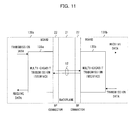
- FIG. 11 is a block diagram showing an example of the configuration of the conventional multi-gigabit transmission system.
- the multi-gigabit transmission system includes a backplane 21, a BP (backplane) connector 22, boards 139a and 139b which are any of the components of the information processing device.
- the boards 139a and 139b include multi-gigabit transmission interfaces 138a and 138b, respectively.
- the multi-gigabit transmission interfaces 138a and 138b correspond to the multi-gigabit transmission interface 138 described above.
- the backplane 21 and the BP connector 22 are components of the multi-gigabit transmission path 12, and wiring length of the backplane 21 and the BP connector 22 is different depending on a mounting slot of each of the board.
- Transmission data from the board 139a is sent from the multi-gigabit transmission interface 138a, is received at the multi-gigabit transmission interface 138b via the multi-gigabit transmission path 12, and then is output to the board 139b as received data.
- transmission data from the board 139b is sent from the multi-gigabit transmission interface 138b, is received at the multi-gigabit transmission interface 138a via the multi-gigabit transmission path 12, and then is output to the board 139a as received data.
- FIG. 12 is a block diagram showing an example of a configuration of a conventional multi-gigabit transmission interface.
- the multi-gigabit transmission interface 138 includes a transmission unit 41, a transmission parameter storage unit 42, a transmission parameter control unit 143, a receiving unit 51, a receive parameter storage unit 52, a receive parameter control unit 153.
- the transmission parameter control unit 143 sets a transmission parameter in the transmission parameter storage unit 42.
- the transmission unit 41 adjusts a waveform of transmission data input from the board in accordance with the transmission parameter in the transmission parameter storage unit 42, and sends the waveform to the multi-gigabit transmission path 12.
- the receive parameter control unit 153 sets a receive parameter in the receive parameter storage unit 52.
- the receiving unit 51 adjusts the waveform received from the multi-gigabit transmission path 12 in accordance with the receive parameter in the receive parameter storage unit 52, and outputs the waveform to the board as receive data.
- control monitoring by the control monitoring board 131 needs the control monitoring transmission path 11 and the control monitoring interface 13 on each of the boards.
- the control monitoring transmission path 11 uses an IIC, a USB, and so on
- the control monitoring interface 13 needs an LSI for exclusive use and has a problem that wiring is congested.
- a waveform of transmission in an actual device needs to be observed to check an amplitude waveform and a jitter margin.
- wiring of an LSI (Large Scale Integrated Circuit) package, and a circuit and wiring of a protective circuit and so on of an LSI chip significantly affect a receive waveform.
- a waveform which can be observed from outside the LSI package by using an IO pin of the LSI is different from the receive waveform at an inputting point of the receiving circuit in the LSI package. Therefore, in order to appropriately evaluate and determine the amplitude and the jitter margin, a large number of man-hours are necessary.
- contacting a probe directly to the LSI chip after opening the LSI package is difficult and unrealistic.
- the transmission unit and the receiving unit need to be tuned in order to correspond to a variety of transmission paths using the backplane and a cable.
- an output amplitude, emphasis strength, a driving impedance, selection of AC/DC coupling, signal speed, and so on which are the transmission parameters used by the transmission unit 41, and equalizer setting, a gain, and so on which are the receive parameters used by the receiving unit 51 need to be set to appropriate values each time a condition of the transmission path changes.
- the appropriate setting value of each of the parameters is different depending on the mounting slot of each of the boards and a destination to which the cable is connected in the backplane.
- the appropriate setting value of each of the parameters is different.
- the appropriate setting value of each of the parameters is different depending on variation of characteristics of parts, and a characteristic change depending on temperature and a power source.
- the mounting slot and the cable length have been fixed.
- the setting value of each parameter has been determined for each of the mounting slots and the cable length, and the setting has been carried out by firmware and a driver at the time of turning on power and resetting the device.
- degree of freedom in a device configuration becomes lower and a tolerable range with respect to a variation of characteristics of parts becomes narrow, therefore a large number of man-hours has been necessary in order to determine the setting value.
- a condition of the transmission path is different depending on a difference between the mounting slots. Therefore, man-hours for optimizing parameters of transmission equipment and receiving equipment have been necessary at each time of mounting.
- An object of the present invention is to provide the information transmission device and the information transmission method, in which the control monitoring transmission system and the multi-gigabit transmission system are achieved with common hardware, and optimization of the multi-gigabit transmission system is facilitated.
- an information transmission device that is included in components and carries out communication between the components in an information processing device including a control monitoring unit that controls and monitors the components, comprising: a transmission control unit that stores a transmission parameter; a transmission unit that has transmission data input thereto in a first transmission speed or a second transmission speed having a transmission speed lower than the first transmission speed, adjusts the transmission data according to the transmission parameter, and sends the transmission data as a transmission signal to the information transmission device which is a connection destination; a receive control unit that stores a receive parameter; and a receiving unit that adjusts a receive signal received from the information transmission device which is a connection destination in accordance with the receive parameter, and outputs the receive signal in the first transmission speed or the second transmission speed as the receive data.
- the transmission unit and the receiving unit use the second transmission speed with respect to data of the control and monitoring.
- the transmission unit and the receiving unit carry out communication in the second transmission speed first, and after the communication is terminated, the transmission unit and the receiving unit carry out communication in the first transmission speed, in a case where any of turning on of power, resetting, and activation is carried out in the component including the information transmission device.
- the transmission unit modulates the transmission data in the second transmission speed by a pattern of the first transmission speed when the transmission data in the second transmission speed is input, and sends the modulated transmission data as a transmission signal; and the receiving unit demodulates the receive signal in the second transmission speed modulated by the pattern of the first transmission speed, and outputs receive data in the second transmission speed.
- the transmission parameter includes any of an output amplitude, emphasis strength, a driving impedance, selection of AC/DC coupling, and a transmission speed; and the receive parameter includes any of an equalizer coefficient and a gain.
- the transmission unit sends a test pattern to the information transmission device which is a connection destination in the first transmission speed, and when the information transmission device which is a connection destination receives the test pattern, an error ratio of the test pattern is measured, and the information transmission device sends a measurement result of the error ratio in the second transmission speed, the receiving unit receives the measurement result of the error ratio, and the transmission control unit changes the transmission parameter based on the measurement result of the error ratio.
- the receiving unit receives a test pattern sent by the information transmission device which is a connection destination in the first transmission speed, and measures an error ratio of the received test pattern, the receive control unit changes the receive parameter based on a measurement result of the error ratio, and the transmission unit sends the measurement result of the error ratio to the information transmission device which is a connection destination in the second transmission speed.
- an information transmission method that carries out communication between components in an information processing device including a control monitoring unit that controls and monitors the components, comprising: a transmission control step that stores a transmission parameter; a transmission step that has transmission data input thereto in a first transmission speed or a second transmission speed having a transmission speed lower than the first transmission speed, adjusts the transmission data according to the transmission parameter, and sends the transmission data as a transmission signal to the component which is a connection destination; a receiving control step that stores a receive parameter; and a receiving step that adjusts a receive signal received from the component which is a connection destination in accordance with the receive parameter, and outputs the receive signal in the first transmission speed or the second transmission speed as the receive data.
- the transmission step and the receiving step use the second transmission speed with respect to data of the control and monitoring.
- the transmission step and the receiving step carry out communication in the second transmission speed first, and after the communication is terminated, the transmission step and the receiving step carry out communication in the first transmission speed, in a case where any of turning on of power, resetting, and activation is carried out in the component.
- the transmission step modulates the transmission data in the second transmission speed by a pattern of the first transmission speed when the transmission data in the second transmission speed is input, and sends the modulated transmission data as a transmission signal; and the receiving step demodulates the receive signal in the second transmission speed modulated by the pattern of the first transmission speed, and outputs receive data in the second transmission speed.
- the transmission parameter includes any of an output amplitude, emphasis strength, a driving impedance, selection of AC/DC coupling, and a transmission speed; and the receive parameter includes any of an equalizer coefficient and a gain.
- the transmission step sends a test pattern to the component which is a connection destination in the first transmission speed, and when the component which is a connection destination receives the test pattern, an error ratio of the test pattern is measured, and a measurement result of the error ratio is transmitted in the second transmission speed, the receiving step receives the measurement result of the error ratio, and the transmission control step changes the transmission parameter based on the measurement result of the error ratio.
- the receiving step receives a test pattern sent by the component which is a connection destination in the first transmission speed, and measures an error ratio of the received test pattern
- the receiving control step changes the receive parameter based on a measurement result of the error ratio
- the transmission step sends the measurement result of the error ratio to the component which is a connection destination in the second transmission speed.
- An information processing device uses a high-speed transmission mode in which optimization of a transmission parameter and a receive parameter is necessary by using multi-gigabit transmission and a low-speed transmission mode in which the optimization of the transmission parameter and the receive parameter is not necessary by using a transmission speed lower than the multi-gigabit transmission in a switching manner in a multi-gigabit transmission interface and a multi-gigabit transmission path. Further, by carrying out control monitoring in the low-speed transmission mode, the number of control monitoring interfaces and control monitoring transmission paths are reduced.
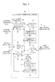
- FIG. 1 is a block diagram showing an example of the configuration of the information processing device according to the present invention.
- reference numerals identical with those in FIG. 10 denote portions same or equivalent to those shown in FIG. 10, and description thereof is omitted here.
- FIG. 10 FIG. 1
- control monitoring board 31 in place of a control monitoring board 131, a crossbar switch board 32 in place of a crossbar switch board 132, a CPU board 33 in place of a CPU board 133, an IO control board 34 in place of an IO control board 134, an SCSI control unit 35 in place of an SCSI control unit 135, a LAN control board 36 in place of a LAN control board 136, a USB control board 37 in place of a USB control board 137, and a multi-gigabit transmission interface 38 in place of a multi-gigabit transmission interface 138.
- the CPU board 33 and the control monitoring board 31 are connected by a control monitoring interface 13 and a control monitoring transmission path 11 as similar to a conventional art.
- each of the other boards which are the crossbar switch board 32, the IO control board 34, the SCSI control board 35, the LAN control board 36, and the USB control board 37, and the control monitoring board 31 do not need the control monitoring transmission path 11 and the control monitoring interface 13 therebetween. Therefore, a large number of the control monitoring transmission paths 11 and the control monitoring interfaces 13 can be reduced.
- FIG. 2 is a block diagram showing an example of the configuration of the multi-gigabit transmission system according to the present invention.
- FIG. 2 includes boards 39a and 39b in place of boards 139a and 139b.
- the boards 39a and 39b include multi-gigabit transmission interfaces 38a and 38b in place of multi-gigabit transmission interfaces 138a and 138b, respectively.
- the multi-gigabit transmission interfaces 38a and 38b correspond to the multi-gigabit transmission interface 38 described above.
- One of the multi-gigabit transmission interfaces 38a and 38b works as a host side and the other works as an lO side to carry out communication.
- High-speed transmission data which is transmission data of the high-speed transmission mode in the board 39a is sent from the multi-gigabit transmission interface 38a, received at the multi-gigabit transmission interface 38b via the multi-gigabit transmission path 12, and then output to the board 39b as high-speed receive data which is receive data of the high-speed transmission mode.
- the high-speed transmission data which is transmission data of the high-speed transmission mode in the board 39b is sent from the multi-gigabit transmission interface 38b, received at the multi-gigabit transmission interface 38a via the multi-gigabit transmission path 12, and then output to the board 39a as the high-speed receive data which is receive data of the high-speed transmission mode.
- low-speed transmission data which is transmission data of the low-speed transmission mode in the board 39a is sent from the multi-gigabit transmission interface 38a, received at the multi-gigabit transmission interface 38b via the multi-gigabit transmission path 12, and then output to the board 39b as low-speed receive data which is receive data of the low-speed transmission mode.
- the low-speed transmission data which is transmission data of the low-speed transmission mode in the board 39b is sent from the multi-gigabit transmission interface 38b, received at the multi-gigabit transmission interface 38a via the multi-gigabit transmission path 12, and then output to the board 39a as the low-speed receive data which is receive data of the low-speed transmission mode.
- FIG. 3 is a block diagram showing an example of a configuration of the multi-gigabit transmission interface according to the present invention.
- the multi-gigabit transmission interface 38 includes a transmission parameter control unit 43 in place of a transmission parameter control unit 143, and a receive parameter control unit 53 in place of a receive parameter control unit 153, and newly includes a test pattern generation unit 44, a modulation unit 45, an SW (switch) 46, a test pattern generation unit 54, a demodulation unit 55, and a BER (Bit Error Rate) measuring unit 56.
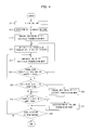
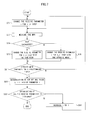
- FIG. 4 is a flowchart showing an example of the operation of the multi-gigabit transmission interface according to the present invention.
- This flow shows operation of the multi-gigabit transmission interface 38a, and operation for carrying out communication in the high-speed transmission mode in the multi-gigabit transmission interface 38a and the multi-gigabit transmission interface 38b.
- this flow is started by any of turning on of power, resetting, and activation of the board 39a including the multi-gigabit transmission interface 38a.
- initial setting is carried out for each part of the multi-gigabit transmission interface 38a (S11).
- the multi-gigabit transmission interfaces 38a works as the host side and the multi-gigabit transmission interfaces 38b works as the IO side.
- the transmission parameter and the receive parameter have previous values stored in a transmission parameter storage unit 42 and a receive parameter storage unit 52, respectively.
- a transmission unit 41 detects the multi-gigabit transmission interface 38b which is a receiving side (S12).
- the multi-gigabit transmission interface 38a carries out communication with the control monitoring board 31 through the multi-gigabit transmission interface 38b in the low-speed transmission mode, thereby the control monitoring by the control monitoring board 31 is carried out (S13).
- the initial setting of the board including the multi-gigabit transmission interface 38a may be carried out from the control monitoring board 31 by the low-speed transmission mode.
- the control monitoring is carried out by communication with the control monitoring board 31 through the multi-gigabit transmission path 12, the CPU board 33, and the control monitoring transmission path 11.
- the multi-gigabit transmission path 12 uses the low-speed transmission mode.
- the control monitoring is carried out by communication with the control monitoring board 31 through the control monitoring transmission path 11, as similar to the conventional art.
- control monitoring board 31 and the crossbar switch board 32 or the other boards may be connected by the multi-gigabit transmission interface 38 and the multi-gigabit transmission path 12, and the control monitoring transmission paths 11 and the control monitoring interfaces 13 may be eliminated to make all the boards carry out communication in the low-speed transmission mode.
- the transmission parameter control unit 43 and the receive parameter control unit 53 set the transmission parameter and the receive parameter, and store the transmission parameter and the receive parameter in the transmission parameter storage unit 42 and the receive parameter storage unit 52, respectively (S21).
- the transmission unit 41 and the receiving unit 51 carry out communication in the high transmission mode in accordance with the transmission parameter storage unit 42 and the receive parameter storage unit 52 (S22). This state is a normal high-speed transmission mode.
- the BER measuring unit 56 determines whether transmission quality meets a predetermined threshold value (S23).
- the transmission quality is checked by using CRC (Cyclic Redundancy Check) and so on.
- CRC Cyclic Redundancy Check
- the transmission unit 41 and the receiving unit 51 determine whether a state in which transmission by the high-speed transmission mode is not carried out continues for a predetermined time (S24). In a case the state in which the transmission is not carried out continues (S24, Y), the transmission unit 41 and the receiving unit 51 carry out communication with the control monitoring board 31 via the multi-gigabit transmission interface 38b in the low-speed transmission mode, thereby the control monitoring by the control monitoring board 31 is carried out (S25), and the operation moves to the processing S26.
- the transmission unit 41 and the receiving unit 51 determine whether there is a change in a state of a mounted board when the board is lower than the other boards (S26). In a case that there is a change in the state (S26, Y), the change in the state is notified to a higher board in the low-speed transmission mode (S27), and the operation moves to processing S28.
- the higher board is the lO control board 34
- the lower boards are the SCSI control board 35, the LAN control board 36, and the USB control board 37 which are connected to the IO control board 34 by the multi-gigabit transmission path 12.
- the transmission unit 41 and the receiving unit 51 determine whether the communication is terminated or not (S28). In a case the communication is not terminated (S28, N), the operation returns to processing S22, and the communication in the high-speed transmission mode is continuously carried out. When the communication is terminated (S28, Y), this flow is terminated.
- the multi-gigabit transmission interface 38a and the multi-gigabit transmission interface 38b carry out automatic tuning of the transmission parameter and the receive parameter.
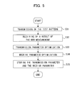
- FIG. 5 is a flowchart showing an example of the operation of the automatic tuning according to the present invention.
- the flowchart shows operation of the multi-gigabit transmission interface 38a and the multi-gigabit transmission interface 38b.
- the SW 46 outputs a test pattern for BER measurement input from the test pattern generation unit 44 to the transmission unit 41, thereby the test pattern is sent to the multi-gigabit transmission interface 38b (S31).
- the BER measuring unit 56 measures a BER
- the SW 46 and the transmission unit 41 send a result of the BER measurement to the multi-gigabit transmission interface 38a.
- the receiving unit 51 receives the result of the BER measurement (S32), and the transmission parameter control unit 43 carries out optimization of the transmission parameter (S33).
- the receive parameter control unit 53 carries out receive parameter optimization (S34).
- the receive parameter control unit 53 of the multi-gigabit transmission interface 38b carries out the receive parameter optimization (S34).
- the parameter optimization on the transmission side at the multi-gigabit transmission interface 38b and the receive parameter optimization at the multi-gigabit transmission interface 38a are carried out.
- the transmission parameter control unit 43 and the receive parameter control unit 53 send the optimized transmission parameter and receive parameter to the control monitoring board 31 in the low-speed transmission mode, the control monitoring board 31 stores the transmission parameter and the receive parameter (S35), and this flow is terminated.
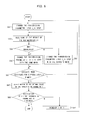
- FIG. 6 is a flowchart showing an example of the operation of the transmission parameter optimization according to the present invention.
- the flowchart shows the operation of the transmission parameter optimization in the multi-gigabit transmission interface 38a.
- a change amount of a transmission parameter i i is an integer between 1 and the number of the transmission parameters
- the change amount in the first time is s_ti step
- an absolute value of the change amount in the second and following times is t_ti step.
- an initial value of i is 1.
- the test pattern is sent from the multi-gigabit transmission interface 38a to the multi-gigabit transmission interface 38b in the high-speed transmission mode.
- the transmission parameter control unit 43 of the multi-gigabit transmission interface 38a changes the transmission parameter i for s_ti step (S51).
- the BER measuring unit 56 measures the BER, and the result of the BER measurement is sent by the modulation unit 45, the SW 46, and the transmission unit 41 to the multi-gigabit transmission interface 38a in the low-speed transmission mode.
- the receiving unit 51 receives the result of the BER measurement in the low-speed transmission mode (S53), and the transmission parameter control unit 43 compares the result of the BER measurement with a previous result of the BER measurement to determine whether the result of the BER measurement decreases or not (S54).
- the transmission parameter control unit 43 changes the transmission parameter i for t_ti step with a mark same as the previous time (S55), and the operation moves to processing S61.
- the transmission parameter control unit 43 changes the transmission parameter i for t_ti step with a mark opposite to the previous time (S56), and the operation moves to the processing S61.
- the transmission parameter control unit 43 determines whether the change to the opposite mark continues for a predetermined times (S61). In a case the change to the opposite mark does not continue (S61, N), the operation returns to processing S53. On the other hand, if the change to the opposite mark continues (S61, Y), the transmission parameter control unit 43 determines a middle value between values before and after the transmission parameter i changes as an optimal value of the transmission parameter i (S62). Next, the transmission parameter control unit 43 determines whether the optimization of all the transmission parameters has finished, that is, whether i matches with the number of the transmission parameters (S63). In a case where the optimization has not finished (S63, N), the transmission parameter control unit 43 increases i by 1 (S64), and the operation returns to processing S51. If the optimization has finished (S63, Y), this flow is terminated.
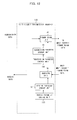
- FIG. 7 is a flowchart showing an example of the operation of the receive parameter optimization according to the present invention.
- the operation of the receive parameter optimization in the multi-gigabit transmission interface 38b is shown.
- a change amount of a receive parameter i i is an integer between 1 and the number of the receive parameters
- the change amount in the first time is s_ri step
- an absolute value of the change amount in the second and following times is t_ri step.
- An initial value of i is 1.
- the test pattern is sent from the multi-gigabit transmission interface 38a to the multi-gigabit transmission interface 38b in the high-speed transmission mode.
- the receive parameter control unit 53 changes the receive parameter i for s_ri step (S71).
- the BER measuring unit 56 measures the BER from the received test pattern (S73).
- the receive parameter control unit 53 determines whether the result of the BER measurement has decreased or not by comparing the result of the BER measurement with the previous result of the BER measurement (S74). In a case where the result of the BER measurement has decreased (S74, Y), the receive parameter control unit 53 changes the receive parameter i for t_ri step with a mark same as a previous one (S75), and the operation moves to processing S81.
- the receive parameter control unit 53 changes the receive parameter i for t_ri step with a mark opposite to the previous one (S76), and the operation moves to processing S81.
- the receive parameter control unit 53 determines whether the change to the opposite mark continues for a predetermined times (S81). In a case where the change to the opposite mark does not continue (S81, N), the operation returns to processing S73. On the other hand, if the opposite mark continues (S81, Y), the receive parameter control unit 53 determines a middle value between values before and after the receive parameter i changes as an optimal value of the receive parameter i (S82). Next, the receive parameter control unit 53 determines whether the optimization of all the receive parameters has finished, that is, whether i matches with the number of the receive parameters (S83). In a case the optimization has not finished (S83, N), the receive parameter control unit 53 increases i by 1 (S84), and the operation returns to processing S71. If the optimization has finished (S83, Y), this flow is terminated.
- the automatic tuning is carried out in the setting of the transmission parameter and the receive parameter, thereby the transmission parameter and the receive parameter can be made close to a value at which the BER becomes minimum.
- the multi-gigabit transmission interface 38 carries out the automatic tuning.
- the setting of the transmission parameter and the receive parameter of the multi-gigabit transmission interface 38 may be carried out from outside.
- the multi-gigabit transmission interface 38 may have the transmission parameter and the receive parameter stored in the control monitoring board 11 transmitted thereto by carrying out communication with the control monitoring board 11 in the low-speed transmission mode, so that the transmission parameter and the receive parameter are stored in the transmission parameter storage unit 42 and the receive parameter storage unit 52.
- the modulation unit 45 In the low-speed transmission mode, the modulation unit 45 generates a repeated pattern of "01" in the transmission speed of the high-speed transmission mode, modulates input low-speed data by the repeated pattern, and outputs the modulated data to the SW46.
- the SW 46 outputs the input from the modulation unit 45 to the transmission unit 41.
- the transmission unit 41 sends the input from the SW 46 in a state that the input is adjusted in accordance with the transmission parameter, and outputs the input to the multi-gigabit transmission path 12.
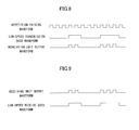
- FIG. 8 is a waveform representing an example of operation of the transmission in the low-speed transmission mode according to the present invention.
- the waveforms represent a repeated pattern waveform, a low-speed transmission data waveform, and a modulation unit output waveform, in the order from the top waveform.
- the SW 46 In the high-speed transmission mode, the SW 46 outputs the high-speed transmission data input from the board 39 to the transmission unit 41.
- the transmission unit 41 transmits the input from the SW 46 in a state where the input is adjusted in accordance with the transmission parameter, and outputs the input to the multi-gigabit transmission path 12.
- the receiving unit 51 receives a waveform received from the multi-gigabit transmission path 12 in a state adjusted in accordance with the receive parameter and outputs the waveform to the demodulation unit 55.
- the demodulation unit 55 allows only high-speed data of repetition of "01" to pass by a BPF (band path filter), and a comparator determines whether or not a level of a signal passing through the BPF has exceeded a predetermined value. Consequently, a result of the determination is output to the board 39 and the transmission parameter control unit 43 as low-speed receive data.
- FIG. 9 shows waveforms representing an example of the receiving in the low-speed transmission mode according to the present invention.
- the waveforms represent a receiving unit output waveform and a demodulation unit output waveform.
- the receiving unit 51 receives a waveform received from the multi-gigabit transmission path 12 in a state that the waveform is adjusted by the receive parameter, and outputs the waveform to the board 39 as high-speed receive data.
- the repetition pattern of "01” is used.
- a repetition pattern of "0011” a repetition pattern of "000111 “, a repetition pattern of "00001111”, and so on may be used.
- the low-speed data which does not require optimization of the transmission parameter and the receive parameter can be transmitted by using the multi-gigabit transmission interface 38 and the multi-gigabit transmission path 12, and the low-speed data can be used for the control monitoring and parameter setting.
- the information transmission device corresponds to the multi-gigabit transmission interface in the embodiment.
- the control monitoring unit corresponds to the control monitoring board in the embodiment.
- the transmission control unit corresponds to the transmission parameter control unit and the transmission parameter storage unit in the embodiment.
- the receive control unit corresponds to the receive parameter control unit and the receive parameter storage unit in the embodiment.
- the transmission unit corresponds to the modulation unit, the SW, the transmission unit, and the test pattern generation unit in the embodiment.
- the receiving unit corresponds to the receiving unit, the demodulation unit, the BER measuring unit, and the test pattern generation unit in the embodiment.
Abstract
Description
- The present invention relates to an information transmission device and information transmission method for carrying out high-speed transmission between components and carrying out control monitoring of the components.
- An information processing device such as a server device and a storage device includes a control monitoring board, and the control monitoring board controls and monitors each board which is a component of the information processing device. For this reason, the control monitoring board and other boards have a control monitoring interface, are connected with a transmission path for an exclusive use, and carry out communication for control monitoring. In addition, along with the information processing device having higher performance and higher speed, a data transmission speed in the information processing device and between the information processing devices has increasingly higher speed. In the information processing device described above, a multi-gigabit transmission system which is high-speed data transmission exceeding 1 Gbps has been used in addition to the communication for the control monitoring.
- Here, a configuration of an information processing device using a conventional multi-gigabit transmission system will be explained. FIG. 10 is a block diagram showing an example of the configuration of the conventional information processing device. This information processing device includes a control
monitoring transmission path 11, amulti-gigabit transmission path 12, acontrol monitoring board 131, acrossbar switch board 132, a CPU (Central Processing Unit)board 133, an IO (Input/Output)control board 134, an SCSI (Small Computer System Interface)control board 135, a LAN (Local Area Network)control board 136, and a USB (Universal Serial Bus)control board 137. - The
control monitoring board 131 carries out control monitoring of thecrossbar switch board 132, theCPU board 133, theIO control board 134, theSCSI control board 135, theLAN control board 136, and theUSB control board 137, which are boards of other components of the information processing device. For this reason, thecontrol monitoring board 131 includes acontrol monitoring interface 13, each board includes thecontrol monitoring interface 13, and thecontrol monitoring interfaces 13 are connected to each other by the controlmonitoring transmission path 11. Further, each board includes amulti-gigabit transmission interface 138 for carrying out multi-gigabit transmission with other boards. Themulti-gigabit transmission interfaces 138 are connected to each other with themulti-gigabit transmission path 12. - Next, a configuration of the conventional multi-gigabit transmission system will be described. FIG. 11 is a block diagram showing an example of the configuration of the conventional multi-gigabit transmission system. The multi-gigabit transmission system includes a
backplane 21, a BP (backplane)connector 22,boards boards multi-gigabit transmission interfaces multi-gigabit transmission interfaces multi-gigabit transmission interface 138 described above. In addition, thebackplane 21 and theBP connector 22 are components of themulti-gigabit transmission path 12, and wiring length of thebackplane 21 and theBP connector 22 is different depending on a mounting slot of each of the board. - Transmission data from the
board 139a is sent from themulti-gigabit transmission interface 138a, is received at themulti-gigabit transmission interface 138b via themulti-gigabit transmission path 12, and then is output to theboard 139b as received data. In a similar manner, transmission data from theboard 139b is sent from themulti-gigabit transmission interface 138b, is received at themulti-gigabit transmission interface 138a via themulti-gigabit transmission path 12, and then is output to theboard 139a as received data. - FIG. 12 is a block diagram showing an example of a configuration of a conventional multi-gigabit transmission interface. The
multi-gigabit transmission interface 138 includes atransmission unit 41, a transmissionparameter storage unit 42, a transmissionparameter control unit 143, areceiving unit 51, a receiveparameter storage unit 52, a receiveparameter control unit 153. The transmissionparameter control unit 143 sets a transmission parameter in the transmissionparameter storage unit 42. Thetransmission unit 41 adjusts a waveform of transmission data input from the board in accordance with the transmission parameter in the transmissionparameter storage unit 42, and sends the waveform to themulti-gigabit transmission path 12. The receiveparameter control unit 153 sets a receive parameter in the receiveparameter storage unit 52. Thereceiving unit 51 adjusts the waveform received from themulti-gigabit transmission path 12 in accordance with the receive parameter in the receiveparameter storage unit 52, and outputs the waveform to the board as receive data. - As described above, in order to ensure communication at a low transmission speed, the control monitoring by the
control monitoring board 131 needs the controlmonitoring transmission path 11 and thecontrol monitoring interface 13 on each of the boards. In addition, the controlmonitoring transmission path 11 uses an IIC, a USB, and so on, and thecontrol monitoring interface 13 needs an LSI for exclusive use and has a problem that wiring is congested. - In addition, in order to guarantee transmission at a high-speed, a waveform of transmission in an actual device needs to be observed to check an amplitude waveform and a jitter margin. In particular, in the multi-gigabit transmission system, wiring of an LSI (Large Scale Integrated Circuit) package, and a circuit and wiring of a protective circuit and so on of an LSI chip significantly affect a receive waveform. However, a waveform which can be observed from outside the LSI package by using an IO pin of the LSI is different from the receive waveform at an inputting point of the receiving circuit in the LSI package. Therefore, in order to appropriately evaluate and determine the amplitude and the jitter margin, a large number of man-hours are necessary. In addition, in evaluation in the actual device, contacting a probe directly to the LSI chip after opening the LSI package is difficult and unrealistic.
- In addition, in the multi-gigabit transmission system used in the information processing device, the transmission unit and the receiving unit need to be tuned in order to correspond to a variety of transmission paths using the backplane and a cable. In order to achieve this, an output amplitude, emphasis strength, a driving impedance, selection of AC/DC coupling, signal speed, and so on which are the transmission parameters used by the
transmission unit 41, and equalizer setting, a gain, and so on which are the receive parameters used by thereceiving unit 51 need to be set to appropriate values each time a condition of the transmission path changes. Further, depending on the mounting slot of each of the boards and a destination to which the cable is connected in the backplane, the appropriate setting value of each of the parameters is different. In addition, depending on variation of characteristics of parts, and a characteristic change depending on temperature and a power source, the appropriate setting value of each of the parameters is different. - For the above reason, the mounting slot and the cable length have been fixed. In addition, the setting value of each parameter has been determined for each of the mounting slots and the cable length, and the setting has been carried out by firmware and a driver at the time of turning on power and resetting the device. In these measures, degree of freedom in a device configuration becomes lower and a tolerable range with respect to a variation of characteristics of parts becomes narrow, therefore a large number of man-hours has been necessary in order to determine the setting value. For example, when the boards having an identical function are mounted in the different mounting slots, a condition of the transmission path is different depending on a difference between the mounting slots. Therefore, man-hours for optimizing parameters of transmission equipment and receiving equipment have been necessary at each time of mounting.
- The present invention is made to solve the problem described above. An object of the present invention is to provide the information transmission device and the information transmission method, in which the control monitoring transmission system and the multi-gigabit transmission system are achieved with common hardware, and optimization of the multi-gigabit transmission system is facilitated.
- In order to achieve the object described above, according to the present invention, there is provided an information transmission device that is included in components and carries out communication between the components in an information processing device including a control monitoring unit that controls and monitors the components, comprising: a transmission control unit that stores a transmission parameter; a transmission unit that has transmission data input thereto in a first transmission speed or a second transmission speed having a transmission speed lower than the first transmission speed, adjusts the transmission data according to the transmission parameter, and sends the transmission data as a transmission signal to the information transmission device which is a connection destination; a receive control unit that stores a receive parameter; and a receiving unit that adjusts a receive signal received from the information transmission device which is a connection destination in accordance with the receive parameter, and outputs the receive signal in the first transmission speed or the second transmission speed as the receive data.
- In the information transmission device according to the present invention, the transmission unit and the receiving unit use the second transmission speed with respect to data of the control and monitoring.
- In the information transmission device according to the present invention, the transmission unit and the receiving unit carry out communication in the second transmission speed first, and after the communication is terminated, the transmission unit and the receiving unit carry out communication in the first transmission speed, in a case where any of turning on of power, resetting, and activation is carried out in the component including the information transmission device.
- In the information transmission device according to the present invention, the transmission unit modulates the transmission data in the second transmission speed by a pattern of the first transmission speed when the transmission data in the second transmission speed is input, and sends the modulated transmission data as a transmission signal; and the receiving unit demodulates the receive signal in the second transmission speed modulated by the pattern of the first transmission speed, and outputs receive data in the second transmission speed.
- In the information transmission device according to the present invention, the transmission parameter includes any of an output amplitude, emphasis strength, a driving impedance, selection of AC/DC coupling, and a transmission speed; and the receive parameter includes any of an equalizer coefficient and a gain.
- In the information transmission device according to the present invention, the transmission unit sends a test pattern to the information transmission device which is a connection destination in the first transmission speed, and when the information transmission device which is a connection destination receives the test pattern, an error ratio of the test pattern is measured, and the information transmission device sends a measurement result of the error ratio in the second transmission speed, the receiving unit receives the measurement result of the error ratio, and the transmission control unit changes the transmission parameter based on the measurement result of the error ratio.
- In the information transmission device according to the present invention, the receiving unit receives a test pattern sent by the information transmission device which is a connection destination in the first transmission speed, and measures an error ratio of the received test pattern, the receive control unit changes the receive parameter based on a measurement result of the error ratio, and the transmission unit sends the measurement result of the error ratio to the information transmission device which is a connection destination in the second transmission speed.
- According to the present invention, there is provided an information transmission method that carries out communication between components in an information processing device including a control monitoring unit that controls and monitors the components, comprising: a transmission control step that stores a transmission parameter; a transmission step that has transmission data input thereto in a first transmission speed or a second transmission speed having a transmission speed lower than the first transmission speed, adjusts the transmission data according to the transmission parameter, and sends the transmission data as a transmission signal to the component which is a connection destination; a receiving control step that stores a receive parameter; and a receiving step that adjusts a receive signal received from the component which is a connection destination in accordance with the receive parameter, and outputs the receive signal in the first transmission speed or the second transmission speed as the receive data.
- In the information transmission method according to the present invention, the transmission step and the receiving step use the second transmission speed with respect to data of the control and monitoring.
- In the information transmission method according to the present invention, the transmission step and the receiving step carry out communication in the second transmission speed first, and after the communication is terminated, the transmission step and the receiving step carry out communication in the first transmission speed, in a case where any of turning on of power, resetting, and activation is carried out in the component.
- In the information transmission method according to the present invention, the transmission step modulates the transmission data in the second transmission speed by a pattern of the first transmission speed when the transmission data in the second transmission speed is input, and sends the modulated transmission data as a transmission signal; and the receiving step demodulates the receive signal in the second transmission speed modulated by the pattern of the first transmission speed, and outputs receive data in the second transmission speed.
- In the information transmission method according to the present invention, the transmission parameter includes any of an output amplitude, emphasis strength, a driving impedance, selection of AC/DC coupling, and a transmission speed; and the receive parameter includes any of an equalizer coefficient and a gain.
- In the information transmission method according to the present invention, the transmission step sends a test pattern to the component which is a connection destination in the first transmission speed, and when the component which is a connection destination receives the test pattern, an error ratio of the test pattern is measured, and a measurement result of the error ratio is transmitted in the second transmission speed, the receiving step receives the measurement result of the error ratio, and the transmission control step changes the transmission parameter based on the measurement result of the error ratio.
- In the information transmission method according to the present invention, the receiving step receives a test pattern sent by the component which is a connection destination in the first transmission speed, and measures an error ratio of the received test pattern, the receiving control step changes the receive parameter based on a measurement result of the error ratio, and the transmission step sends the measurement result of the error ratio to the component which is a connection destination in the second transmission speed.
-
- FIG. 1 is a block diagram showing an example of a configuration of an information processing device according to the present invention;
- FIG. 2 is a block diagram showing an example of a configuration of a multi-gigabit transmission system according to the present invention;
- FIG. 3 is a block diagram showing an example of a configuration of a multi-gigabit transmission interface according to the present invention;
- FIG. 4 is a flowchart showing an example of operation of the multi-gigabit transmission interface according to the present invention;
- FIG. 5 is a flowchart showing an example of operation of automatic tuning according to the present invention;
- FIG. 6 is a flowchart showing an example of operation of a transmission parameter optimization according to the present invention;
- FIG. 7 is a flowchart showing an example of operation of a receive parameter optimization according to the present invention;
- FIG. 8 is a waveform representing an example of transmission operation in a low-speed transmission mode according to the present invention;
- FIG. 9 is a waveform representing an example of receiving operation in a low-speed transmission mode according to the present invention;
- FIG. 10 is a block diagram showing an example of a configuration of a conventional information processing device;
- FIG. 11 is a block diagram showing an example of a configuration of a conventional multi-gigabit transmission system; and
- FIG. 12 is a block diagram showing an example of a configuration of a conventional multi-gigabit transmission interface.
- Hereinafter, an embodiment of the present invention will be described with reference to the accompanying drawings.
- An information processing device according to the present invention uses a high-speed transmission mode in which optimization of a transmission parameter and a receive parameter is necessary by using multi-gigabit transmission and a low-speed transmission mode in which the optimization of the transmission parameter and the receive parameter is not necessary by using a transmission speed lower than the multi-gigabit transmission in a switching manner in a multi-gigabit transmission interface and a multi-gigabit transmission path. Further, by carrying out control monitoring in the low-speed transmission mode, the number of control monitoring interfaces and control monitoring transmission paths are reduced.
- First, a configuration of the information processing device according to the present invention will be described.
- FIG. 1 is a block diagram showing an example of the configuration of the information processing device according to the present invention. In FIG. 1, reference numerals identical with those in FIG. 10 denote portions same or equivalent to those shown in FIG. 10, and description thereof is omitted here. As compared with FIG. 10, FIG. 1 includes a
control monitoring board 31 in place of acontrol monitoring board 131, acrossbar switch board 32 in place of acrossbar switch board 132, aCPU board 33 in place of aCPU board 133, anIO control board 34 in place of anIO control board 134, anSCSI control unit 35 in place of anSCSI control unit 135, aLAN control board 36 in place of aLAN control board 136, aUSB control board 37 in place of aUSB control board 137, and amulti-gigabit transmission interface 38 in place of amulti-gigabit transmission interface 138. - In the information processing device according to the present invention, the
CPU board 33 and thecontrol monitoring board 31 are connected by acontrol monitoring interface 13 and a controlmonitoring transmission path 11 as similar to a conventional art. However, each of the other boards, which are thecrossbar switch board 32, theIO control board 34, theSCSI control board 35, theLAN control board 36, and theUSB control board 37, and thecontrol monitoring board 31 do not need the controlmonitoring transmission path 11 and thecontrol monitoring interface 13 therebetween. Therefore, a large number of the controlmonitoring transmission paths 11 and the control monitoring interfaces 13 can be reduced. - Next, a configuration of the multi-gigabit transmission system according to the present invention will be described.
- FIG. 2 is a block diagram showing an example of the configuration of the multi-gigabit transmission system according to the present invention. In FIG. 2, reference numerals identical with those in FIG. 11 denote portions same or equivalent to those shown in FIG. 11, and description thereof is omitted here. As compared with FIG. 11, FIG. 2 includes
boards boards boards multi-gigabit transmission interfaces multi-gigabit transmission interfaces multi-gigabit transmission interfaces multi-gigabit transmission interface 38 described above. One of themulti-gigabit transmission interfaces - High-speed transmission data which is transmission data of the high-speed transmission mode in the
board 39a is sent from themulti-gigabit transmission interface 38a, received at themulti-gigabit transmission interface 38b via themulti-gigabit transmission path 12, and then output to theboard 39b as high-speed receive data which is receive data of the high-speed transmission mode. In a similar manner, the high-speed transmission data which is transmission data of the high-speed transmission mode in theboard 39b is sent from themulti-gigabit transmission interface 38b, received at themulti-gigabit transmission interface 38a via themulti-gigabit transmission path 12, and then output to theboard 39a as the high-speed receive data which is receive data of the high-speed transmission mode. - In addition, low-speed transmission data which is transmission data of the low-speed transmission mode in the
board 39a is sent from themulti-gigabit transmission interface 38a, received at themulti-gigabit transmission interface 38b via themulti-gigabit transmission path 12, and then output to theboard 39b as low-speed receive data which is receive data of the low-speed transmission mode. In a similar manner, the low-speed transmission data which is transmission data of the low-speed transmission mode in theboard 39b is sent from themulti-gigabit transmission interface 38b, received at themulti-gigabit transmission interface 38a via themulti-gigabit transmission path 12, and then output to theboard 39a as the low-speed receive data which is receive data of the low-speed transmission mode. - FIG. 3 is a block diagram showing an example of a configuration of the multi-gigabit transmission interface according to the present invention. In FIG. 3, reference numerals identical with those in FIG. 12 denote portions same or equivalent to those shown in FIG. 12, and description thereof is omitted here. As compared with the
multi-gigabit transmission interface 138, themulti-gigabit transmission interface 38 includes a transmissionparameter control unit 43 in place of a transmissionparameter control unit 143, and a receiveparameter control unit 53 in place of a receiveparameter control unit 153, and newly includes a testpattern generation unit 44, amodulation unit 45, an SW (switch) 46, a testpattern generation unit 54, ademodulation unit 55, and a BER (Bit Error Rate)measuring unit 56. - Next, operation of the multi-gigabit transmission interface according to the present invention will be described.
- FIG. 4 is a flowchart showing an example of the operation of the multi-gigabit transmission interface according to the present invention. This flow shows operation of the
multi-gigabit transmission interface 38a, and operation for carrying out communication in the high-speed transmission mode in themulti-gigabit transmission interface 38a and themulti-gigabit transmission interface 38b. In addition, this flow is started by any of turning on of power, resetting, and activation of theboard 39a including themulti-gigabit transmission interface 38a. - First, initial setting is carried out for each part of the
multi-gigabit transmission interface 38a (S11). Here, themulti-gigabit transmission interfaces 38a works as the host side and the multi-gigabit transmission interfaces 38b works as the IO side. In addition, the transmission parameter and the receive parameter have previous values stored in a transmissionparameter storage unit 42 and a receiveparameter storage unit 52, respectively. Next, atransmission unit 41 detects themulti-gigabit transmission interface 38b which is a receiving side (S12). Next, themulti-gigabit transmission interface 38a carries out communication with thecontrol monitoring board 31 through themulti-gigabit transmission interface 38b in the low-speed transmission mode, thereby the control monitoring by thecontrol monitoring board 31 is carried out (S13). Here, the initial setting of the board including themulti-gigabit transmission interface 38a may be carried out from thecontrol monitoring board 31 by the low-speed transmission mode. - In the present embodiment, if the board including the
multi-gigabit transmission interface 38a is the board other than theCPU board 33, the control monitoring is carried out by communication with thecontrol monitoring board 31 through themulti-gigabit transmission path 12, theCPU board 33, and the controlmonitoring transmission path 11. Themulti-gigabit transmission path 12 uses the low-speed transmission mode. On the other hand, if theboard 39a including themulti-gigabit transmission interface 38a is theCPU board 33, the control monitoring is carried out by communication with thecontrol monitoring board 31 through the controlmonitoring transmission path 11, as similar to the conventional art. Thecontrol monitoring board 31 and thecrossbar switch board 32 or the other boards may be connected by themulti-gigabit transmission interface 38 and themulti-gigabit transmission path 12, and the controlmonitoring transmission paths 11 and the control monitoring interfaces 13 may be eliminated to make all the boards carry out communication in the low-speed transmission mode. - Next, the transmission
parameter control unit 43 and the receiveparameter control unit 53 set the transmission parameter and the receive parameter, and store the transmission parameter and the receive parameter in the transmissionparameter storage unit 42 and the receiveparameter storage unit 52, respectively (S21). Next, thetransmission unit 41 and the receivingunit 51 carry out communication in the high transmission mode in accordance with the transmissionparameter storage unit 42 and the receive parameter storage unit 52 (S22). This state is a normal high-speed transmission mode. Next, theBER measuring unit 56 determines whether transmission quality meets a predetermined threshold value (S23). Here, the transmission quality is checked by using CRC (Cyclic Redundancy Check) and so on. When the transmission quality does not meet the predetermined threshold value (S23, Y), the operation returns to processing S21, and the transmission parameter and the receive parameter are set again. - On the other hand, in a case the transmission quality meets the predetermined threshold value (S23, N), the
transmission unit 41 and the receivingunit 51 determine whether a state in which transmission by the high-speed transmission mode is not carried out continues for a predetermined time (S24). In a case the state in which the transmission is not carried out continues (S24, Y), thetransmission unit 41 and the receivingunit 51 carry out communication with thecontrol monitoring board 31 via themulti-gigabit transmission interface 38b in the low-speed transmission mode, thereby the control monitoring by thecontrol monitoring board 31 is carried out (S25), and the operation moves to the processing S26. - On the other hand, in a case that a state in which the transmission is not carried out does not continue (S24, N), the
transmission unit 41 and the receivingunit 51 determine whether there is a change in a state of a mounted board when the board is lower than the other boards (S26). In a case that there is a change in the state (S26, Y), the change in the state is notified to a higher board in the low-speed transmission mode (S27), and the operation moves to processing S28. Here, for example, the higher board is thelO control board 34, and the lower boards are theSCSI control board 35, theLAN control board 36, and theUSB control board 37 which are connected to theIO control board 34 by themulti-gigabit transmission path 12. On the other hand, in a case that there is not the change in the state (S26, N), thetransmission unit 41 and the receivingunit 51 determine whether the communication is terminated or not (S28). In a case the communication is not terminated (S28, N), the operation returns to processing S22, and the communication in the high-speed transmission mode is continuously carried out. When the communication is terminated (S28, Y), this flow is terminated. - In the setting of the transmission parameter and the receive parameter described above, the
multi-gigabit transmission interface 38a and themulti-gigabit transmission interface 38b carry out automatic tuning of the transmission parameter and the receive parameter. - Next, operation of the automatic tuning according to the present invention will be described.
- FIG. 5 is a flowchart showing an example of the operation of the automatic tuning according to the present invention. Here, the flowchart shows operation of the
multi-gigabit transmission interface 38a and themulti-gigabit transmission interface 38b. First, in themulti-gigabit transmission interface 38a, theSW 46 outputs a test pattern for BER measurement input from the testpattern generation unit 44 to thetransmission unit 41, thereby the test pattern is sent to themulti-gigabit transmission interface 38b (S31). In themulti-gigabit transmission interface 38b that receives the test pattern, theBER measuring unit 56 measures a BER, and theSW 46 and thetransmission unit 41 send a result of the BER measurement to themulti-gigabit transmission interface 38a. Next, in themulti-gigabit transmission interface 38a, the receivingunit 51 receives the result of the BER measurement (S32), and the transmissionparameter control unit 43 carries out optimization of the transmission parameter (S33). The receiveparameter control unit 53 carries out receive parameter optimization (S34). - After parameter optimization on a transmission side at the
multi-gigabit transmission interface 38a is completed, the receiveparameter control unit 53 of themulti-gigabit transmission interface 38b carries out the receive parameter optimization (S34). In a similar manner, the parameter optimization on the transmission side at themulti-gigabit transmission interface 38b and the receive parameter optimization at themulti-gigabit transmission interface 38a are carried out. Next, the transmissionparameter control unit 43 and the receiveparameter control unit 53 send the optimized transmission parameter and receive parameter to thecontrol monitoring board 31 in the low-speed transmission mode, thecontrol monitoring board 31 stores the transmission parameter and the receive parameter (S35), and this flow is terminated. - Next, operation of transmission parameter optimization will be described.
- FIG. 6 is a flowchart showing an example of the operation of the transmission parameter optimization according to the present invention. Here, the flowchart shows the operation of the transmission parameter optimization in the
multi-gigabit transmission interface 38a. In addition, as a change amount of a transmission parameter i (i is an integer between 1 and the number of the transmission parameters), the change amount in the first time is s_ti step, and an absolute value of the change amount in the second and following times is t_ti step. In addition, an initial value of i is 1. As described above, the test pattern is sent from themulti-gigabit transmission interface 38a to themulti-gigabit transmission interface 38b in the high-speed transmission mode. - First, the transmission
parameter control unit 43 of themulti-gigabit transmission interface 38a changes the transmission parameter i for s_ti step (S51). Next, in themulti-gigabit transmission interface 38b, theBER measuring unit 56 measures the BER, and the result of the BER measurement is sent by themodulation unit 45, theSW 46, and thetransmission unit 41 to themulti-gigabit transmission interface 38a in the low-speed transmission mode. Next, in themulti-gigabit transmission interface 38a, the receivingunit 51 receives the result of the BER measurement in the low-speed transmission mode (S53), and the transmissionparameter control unit 43 compares the result of the BER measurement with a previous result of the BER measurement to determine whether the result of the BER measurement decreases or not (S54). In a case where the result of the BER measurement decreases (S54, Y), the transmissionparameter control unit 43 changes the transmission parameter i for t_ti step with a mark same as the previous time (S55), and the operation moves to processing S61. On the other hand, in a case where the result of the BER measurement does not decrease (S54, N), the transmissionparameter control unit 43 changes the transmission parameter i for t_ti step with a mark opposite to the previous time (S56), and the operation moves to the processing S61. - Next, the transmission
parameter control unit 43 determines whether the change to the opposite mark continues for a predetermined times (S61). In a case the change to the opposite mark does not continue (S61, N), the operation returns to processing S53. On the other hand, if the change to the opposite mark continues (S61, Y), the transmissionparameter control unit 43 determines a middle value between values before and after the transmission parameter i changes as an optimal value of the transmission parameter i (S62). Next, the transmissionparameter control unit 43 determines whether the optimization of all the transmission parameters has finished, that is, whether i matches with the number of the transmission parameters (S63). In a case where the optimization has not finished (S63, N), the transmissionparameter control unit 43 increases i by 1 (S64), and the operation returns to processing S51. If the optimization has finished (S63, Y), this flow is terminated. - Next, operation of the optimization of the receive parameter will be described.
- FIG. 7 is a flowchart showing an example of the operation of the receive parameter optimization according to the present invention. Here, the operation of the receive parameter optimization in the
multi-gigabit transmission interface 38b is shown. In addition, as a change amount of a receive parameter i (i is an integer between 1 and the number of the receive parameters), the change amount in the first time is s_ri step, and an absolute value of the change amount in the second and following times is t_ri step. An initial value of i is 1. As described above, the test pattern is sent from themulti-gigabit transmission interface 38a to themulti-gigabit transmission interface 38b in the high-speed transmission mode. - First, in the
multi-gigabit transmission interface 38b, the receiveparameter control unit 53 changes the receive parameter i for s_ri step (S71). Next, theBER measuring unit 56 measures the BER from the received test pattern (S73). Next, the receiveparameter control unit 53 determines whether the result of the BER measurement has decreased or not by comparing the result of the BER measurement with the previous result of the BER measurement (S74). In a case where the result of the BER measurement has decreased (S74, Y), the receiveparameter control unit 53 changes the receive parameter i for t_ri step with a mark same as a previous one (S75), and the operation moves to processing S81. On the other hand, if the result of the BER measurement has not decreased (S74, N), the receiveparameter control unit 53 changes the receive parameter i for t_ri step with a mark opposite to the previous one (S76), and the operation moves to processing S81. - Next, the receive
parameter control unit 53 determines whether the change to the opposite mark continues for a predetermined times (S81). In a case where the change to the opposite mark does not continue (S81, N), the operation returns to processing S73. On the other hand, if the opposite mark continues (S81, Y), the receiveparameter control unit 53 determines a middle value between values before and after the receive parameter i changes as an optimal value of the receive parameter i (S82). Next, the receiveparameter control unit 53 determines whether the optimization of all the receive parameters has finished, that is, whether i matches with the number of the receive parameters (S83). In a case the optimization has not finished (S83, N), the receiveparameter control unit 53 increases i by 1 (S84), and the operation returns to processing S71. If the optimization has finished (S83, Y), this flow is terminated. - As described above, the automatic tuning is carried out in the setting of the transmission parameter and the receive parameter, thereby the transmission parameter and the receive parameter can be made close to a value at which the BER becomes minimum. In the present embodiment, it has been described that the
multi-gigabit transmission interface 38 carries out the automatic tuning. However, the setting of the transmission parameter and the receive parameter of themulti-gigabit transmission interface 38 may be carried out from outside. In a case where the transmission parameter and the receive parameter do not converge in the transmission parameter optimization and the receive parameter optimization, themulti-gigabit transmission interface 38 may have the transmission parameter and the receive parameter stored in thecontrol monitoring board 11 transmitted thereto by carrying out communication with thecontrol monitoring board 11 in the low-speed transmission mode, so that the transmission parameter and the receive parameter are stored in the transmissionparameter storage unit 42 and the receiveparameter storage unit 52. - Next, operation of the transmission in the low-speed transmission mode and the high-speed transmission mode will be described.
- In the low-speed transmission mode, the
modulation unit 45 generates a repeated pattern of "01" in the transmission speed of the high-speed transmission mode, modulates input low-speed data by the repeated pattern, and outputs the modulated data to the SW46. TheSW 46 outputs the input from themodulation unit 45 to thetransmission unit 41. Thetransmission unit 41 sends the input from theSW 46 in a state that the input is adjusted in accordance with the transmission parameter, and outputs the input to themulti-gigabit transmission path 12. FIG. 8 is a waveform representing an example of operation of the transmission in the low-speed transmission mode according to the present invention. The waveforms represent a repeated pattern waveform, a low-speed transmission data waveform, and a modulation unit output waveform, in the order from the top waveform. In the high-speed transmission mode, theSW 46 outputs the high-speed transmission data input from the board 39 to thetransmission unit 41. Thetransmission unit 41 transmits the input from theSW 46 in a state where the input is adjusted in accordance with the transmission parameter, and outputs the input to themulti-gigabit transmission path 12. - Next, operation of receiving in the low-speed transmission mode and the high-speed transmission mode will be described.
- In the low-speed transmission mode, the receiving
unit 51 receives a waveform received from themulti-gigabit transmission path 12 in a state adjusted in accordance with the receive parameter and outputs the waveform to thedemodulation unit 55. Thedemodulation unit 55 allows only high-speed data of repetition of "01" to pass by a BPF (band path filter), and a comparator determines whether or not a level of a signal passing through the BPF has exceeded a predetermined value. Consequently, a result of the determination is output to the board 39 and the transmissionparameter control unit 43 as low-speed receive data. FIG. 9 shows waveforms representing an example of the receiving in the low-speed transmission mode according to the present invention. From the top, the waveforms represent a receiving unit output waveform and a demodulation unit output waveform. In addition, in the high-speed transmission mode, the receivingunit 51 receives a waveform received from themulti-gigabit transmission path 12 in a state that the waveform is adjusted by the receive parameter, and outputs the waveform to the board 39 as high-speed receive data. - Here, the repetition pattern of "01" is used. However, a repetition pattern of "0011 ", a repetition pattern of "000111 ", a repetition pattern of "00001111", and so on may be used.
- By the operation of the low-speed transmission mode described above, the low-speed data which does not require optimization of the transmission parameter and the receive parameter can be transmitted by using the
multi-gigabit transmission interface 38 and themulti-gigabit transmission path 12, and the low-speed data can be used for the control monitoring and parameter setting. - The information transmission device corresponds to the multi-gigabit transmission interface in the embodiment. In addition, the control monitoring unit corresponds to the control monitoring board in the embodiment. The transmission control unit corresponds to the transmission parameter control unit and the transmission parameter storage unit in the embodiment. The receive control unit corresponds to the receive parameter control unit and the receive parameter storage unit in the embodiment. The transmission unit corresponds to the modulation unit, the SW, the transmission unit, and the test pattern generation unit in the embodiment. The receiving unit corresponds to the receiving unit, the demodulation unit, the BER measuring unit, and the test pattern generation unit in the embodiment.
- As described above, by reducing the number of the control monitoring interfaces and the control monitoring transmission paths, wiring space and circuit components in the information processing devices can be significantly reduced, and congestion between transmission paths can be reduced. By carrying out the automatic tuning of the transmission parameter and the receive parameter, high quality transmission can be achieved even when a condition of the transmission path changes.
Claims (14)
- An information transmission device that is included in components and carries out communication between the components in an information processing device including a control monitoring unit that controls and monitors the components, comprising:a transmission control unit that stores a transmission parameter;a transmission unit that has transmission data input thereto in a first transmission speed or a second transmission speed having a transmission speed lower than the first transmission speed, adjusts the transmission data according to the transmission parameter, and sends the transmission data as a transmission signal to the information transmission device which is a connection destination;a receive control unit that stores a receive parameter; anda receiving unit that adjusts a receive signal received from the information transmission device which is a connection destination in accordance with the receive parameter, and outputs the receive signal in the first transmission speed or the second transmission speed as the receive data.
- The information transmission device according to claim 1, wherein
the transmission unit and the receiving unit use the second transmission speed with respect to data of the control and monitoring. - The information transmission device according to claim 2, wherein
the transmission unit and the receiving unit carry out communication in the second transmission speed first, and after the communication is terminated, the transmission unit and the receiving unit carry out communication in the first transmission speed, in a case where any of turning on of power, resetting, and activation is carried out in the component including the information transmission device. - The information transmission device according to claim 3, wherein
the transmission unit modulates the transmission data in the second transmission speed by a pattern of the first transmission speed when the transmission data in the second transmission speed is input, and sends the modulated transmission data as a transmission signal, and
the receiving unit demodulates the receive signal in the second transmission speed modulated by the pattern of the first transmission speed, and outputs receive data in the second transmission speed. - The information transmission device according to claim 4, wherein
the transmission parameter includes any of an output amplitude, emphasis strength, a driving impedance, selection of AC/DC coupling, and a transmission speed, and
the receive parameter includes any of an equalizer coefficient and a gain. - The information transmission device according to claim 5, wherein
the transmission unit sends a test pattern to the information transmission device which is a connection destination in the first transmission speed,
when the information transmission device which is a connection destination receives the test pattern, an error ratio of the test pattern is measured, and the information transmission device sends a measurement result of the error ratio in the second transmission speed, the receiving unit receives the measurement result of the error ratio, and
the transmission control unit changes the transmission parameter based on the measurement result of the error ratio. - The information transmission device according to claim 5, wherein
the receiving unit receives a test pattern sent by the information transmission device which is a connection destination in the first transmission speed, and measures an error ratio of the received test pattern,
the receive control unit changes the receive parameter based on a measurement result of the error ratio, and
the transmission unit sends the measurement result of the error ratio to the information transmission device which is a connection destination in the second transmission speed. - An information transmission method that carries out communication between components in an information processing device including a control monitoring unit that controls and monitors the components, comprising:a transmission control step that stores a transmission parameter;a transmission step that has transmission data input thereto in a first transmission speed or a second transmission speed having a transmission speed lower than the first transmission speed, adjusts the transmission data according to the transmission parameter, and sends the transmission data as a transmission signal to the component which is a connection destination;a receiving control step that stores a receive parameter; anda receiving step that adjusts a receive signal received from the component which is a connection destination in accordance with the receive parameter, and outputs the receive signal in the first transmission speed or the second transmission speed as the receive data.
- The information transmission method according to claim 8, wherein
the transmission step and the receiving step use the second transmission speed with respect to data of the control and monitoring. - The information transmission method according to claim 9, wherein
the transmission step and the receiving step carry out communication in the second transmission speed first, and after the communication is terminated, the transmission step and the receiving step carry out communication in the first transmission speed, in a case where any of turning on of power, resetting, and activation is carried out in the component. - The information transmission method according to claim 10, wherein
the transmission step modulates the transmission data in the second transmission speed by a pattern of the first transmission speed when the transmission data in the second transmission speed is input, and sends the modulated transmission data as a transmission signal, and
the receiving step demodulates the receive signal with the second transmission speed modulated by the pattern of the first transmission speed, and outputs receive data in the second transmission speed. - The information transmission method according to claim 11, wherein
the transmission parameter includes any of an output amplitude, emphasis strength, a driving impedance, selection of AC/DC coupling, and a transmission speed, and
the receive parameter includes any of an equalizer coefficient and a gain. - The information transmission method according to claim 12, wherein
the transmission step sends a test pattern to the component which is a connection destination in the first transmission speed,
when the component which is a connection destination receives the test pattern, an error ratio of the test pattern is measured, and a measurement result of the error ratio is transmitted in the second transmission speed, the receiving step receives the measurement result of the error ratio, and
the transmission control step changes the transmission parameter based on the measurement result of the error ratio. - The information transmission method according to claim 12, wherein
the receiving step receives a test pattern sent by the component which is a connection destination in the first transmission speed, and measures an error ratio of the received test pattern,
the receiving control step changes the receive parameter based on a measurement result of the error ratio, and
the transmission step sends the measurement result of the error ratio to the component which is a connection destination in the second transmission speed.
Applications Claiming Priority (1)
| Application Number | Priority Date | Filing Date | Title |
|---|---|---|---|
| PCT/JP2005/005131 WO2006100754A1 (en) | 2005-03-22 | 2005-03-22 | Information transmitting apparatus and information transmitting method |
Publications (3)
| Publication Number | Publication Date |
|---|---|
| EP1879110A1 true EP1879110A1 (en) | 2008-01-16 |
| EP1879110A4 EP1879110A4 (en) | 2008-07-02 |
| EP1879110B1 EP1879110B1 (en) | 2009-09-30 |
Family
ID=37023451
Family Applications (1)
| Application Number | Title | Priority Date | Filing Date |
|---|---|---|---|
| EP05727081A Expired - Fee Related EP1879110B1 (en) | 2005-03-22 | 2005-03-22 | Information transmitting apparatus and information transmitting method |
Country Status (6)
| Country | Link |
|---|---|
| US (1) | US7895366B2 (en) |
| EP (1) | EP1879110B1 (en) |
| JP (1) | JP4680255B2 (en) |
| CN (1) | CN100541459C (en) |
| DE (1) | DE602005016976D1 (en) |
| WO (1) | WO2006100754A1 (en) |
Cited By (1)
| Publication number | Priority date | Publication date | Assignee | Title |
|---|---|---|---|---|
| EP2693649A1 (en) * | 2011-03-31 | 2014-02-05 | Fujitsu Limited | Information processing apparatus, information processing system, and communication control method |
Families Citing this family (11)
| Publication number | Priority date | Publication date | Assignee | Title |
|---|---|---|---|---|
| JPWO2012140783A1 (en) * | 2011-04-15 | 2014-07-28 | 富士通株式会社 | Autonomous initialization method for opposite port of semiconductor integrated circuit and semiconductor integrated circuit |
| JP5342039B2 (en) * | 2011-06-15 | 2013-11-13 | 株式会社東芝 | Electronics |
| CN103236739B (en) * | 2013-04-11 | 2016-02-17 | 国家电网公司 | The remote measurement amount monitoring device of measure and control device and monitoring method |
| JP2016133972A (en) * | 2015-01-19 | 2016-07-25 | 富士ゼロックス株式会社 | Communication system and image forming apparatus |
| CN104915303B (en) * | 2015-06-23 | 2017-11-21 | 北京工业大学 | High speed digital I based on PXIe buses/O systems |
| US20170176534A1 (en) * | 2015-12-18 | 2017-06-22 | Intel Corporation | Self-characterizing high-speed communication interfaces |
| CN108964836B (en) * | 2017-05-27 | 2021-07-20 | 龙芯中科(北京)信息技术有限公司 | Data decoding method and device |
| JP2019010853A (en) * | 2017-07-03 | 2019-01-24 | 富士ゼロックス株式会社 | Printer controller |
| JP7059860B2 (en) * | 2018-08-06 | 2022-04-26 | 富士通株式会社 | Parameter setting Transmission / reception system and parameter setting method |
| CN109586964B (en) * | 2018-11-30 | 2022-02-08 | 联芸科技(杭州)有限公司 | Local port for bidirectional communication and port training method |
| US20210303427A1 (en) * | 2020-03-26 | 2021-09-30 | Rohde & Schwarz Gmbh & Co. Kg | System for testing a blockchain enabled device-under-test |
Citations (3)
| Publication number | Priority date | Publication date | Assignee | Title |
|---|---|---|---|---|
| US4890316A (en) * | 1988-10-28 | 1989-12-26 | Walsh Dale M | Modem for communicating at high speed over voice-grade telephone circuits |
| DE19939568C1 (en) * | 1999-08-20 | 2001-02-08 | Pilz Gmbh & Co | Data transmission rate setting method for field bus system for safety critical process control has transmission rate set to higher data rate by central control after intial signalling of substations connected to field bus |
| US20040243666A1 (en) * | 2003-05-29 | 2004-12-02 | Wood Robert B. | Method and apparatus for automatic Phy calibration based on negotiated link speed |
Family Cites Families (8)
| Publication number | Priority date | Publication date | Assignee | Title |
|---|---|---|---|---|
| US5751701A (en) * | 1996-07-19 | 1998-05-12 | Globespan Technologies, Inc. | Rate adaptive digital subscriber line ("RADSL") modem |
| US7302186B2 (en) * | 2001-02-05 | 2007-11-27 | Finisar Corporation | Optical transceiver and host adapter with memory mapped monitoring circuitry |
| US6791942B2 (en) | 2001-06-20 | 2004-09-14 | General Instrument Corporation | Dynamic ethernet power management |
| US7023876B2 (en) * | 2001-07-09 | 2006-04-04 | Quantum Corporation | Point-to-point protocol |
| JP3961866B2 (en) * | 2002-03-27 | 2007-08-22 | 富士通株式会社 | COMMUNICATION METHOD, COMMUNICATION DEVICE, AND SOFTWARE PROGRAM |
| JP3945288B2 (en) * | 2002-03-29 | 2007-07-18 | 富士通株式会社 | LAN parameter matching program, LAN parameter matching method, and LAN parameter matching system |
| US20040147281A1 (en) * | 2002-11-12 | 2004-07-29 | Integration Associates Inc. | Transmitter and receiver circuits with controller-less operation capability |
| KR100771715B1 (en) * | 2003-09-02 | 2007-10-30 | 엘지전자 주식회사 | Apparatus and method for controlling data communication for wireless LAN |
-
2005
- 2005-03-22 EP EP05727081A patent/EP1879110B1/en not_active Expired - Fee Related
- 2005-03-22 WO PCT/JP2005/005131 patent/WO2006100754A1/en not_active Application Discontinuation
- 2005-03-22 JP JP2007509108A patent/JP4680255B2/en not_active Expired - Fee Related
- 2005-03-22 DE DE602005016976T patent/DE602005016976D1/en active Active
- 2005-03-22 CN CNB2005800465991A patent/CN100541459C/en not_active Expired - Fee Related
-
2007
- 2007-09-18 US US11/856,972 patent/US7895366B2/en not_active Expired - Fee Related
Patent Citations (3)
| Publication number | Priority date | Publication date | Assignee | Title |
|---|---|---|---|---|
| US4890316A (en) * | 1988-10-28 | 1989-12-26 | Walsh Dale M | Modem for communicating at high speed over voice-grade telephone circuits |
| DE19939568C1 (en) * | 1999-08-20 | 2001-02-08 | Pilz Gmbh & Co | Data transmission rate setting method for field bus system for safety critical process control has transmission rate set to higher data rate by central control after intial signalling of substations connected to field bus |
| US20040243666A1 (en) * | 2003-05-29 | 2004-12-02 | Wood Robert B. | Method and apparatus for automatic Phy calibration based on negotiated link speed |
Non-Patent Citations (1)
| Title |
|---|
| See also references of WO2006100754A1 * |
Cited By (2)
| Publication number | Priority date | Publication date | Assignee | Title |
|---|---|---|---|---|
| EP2693649A1 (en) * | 2011-03-31 | 2014-02-05 | Fujitsu Limited | Information processing apparatus, information processing system, and communication control method |
| EP2693649A4 (en) * | 2011-03-31 | 2014-08-20 | Fujitsu Ltd | Information processing apparatus, information processing system, and communication control method |
Also Published As
| Publication number | Publication date |
|---|---|
| EP1879110A4 (en) | 2008-07-02 |
| US7895366B2 (en) | 2011-02-22 |
| WO2006100754A1 (en) | 2006-09-28 |
| EP1879110B1 (en) | 2009-09-30 |
| JP4680255B2 (en) | 2011-05-11 |
| CN100541459C (en) | 2009-09-16 |
| US20080022022A1 (en) | 2008-01-24 |
| JPWO2006100754A1 (en) | 2008-08-28 |
| DE602005016976D1 (en) | 2009-11-12 |
| CN101103340A (en) | 2008-01-09 |
Similar Documents
| Publication | Publication Date | Title |
|---|---|---|
| EP1879110B1 (en) | Information transmitting apparatus and information transmitting method | |
| EP2183675B1 (en) | Apparatus and method for detecting cable length in a storage subsystem with wide ports | |
| EP1155519B1 (en) | Electro-optic interface system and method of operation | |
| KR101031393B1 (en) | Signal transmission device and method | |
| TWI564725B (en) | Transmission circuit for i/o interface and signal transmission method thereof | |
| US20090153213A1 (en) | Method for reducing delay difference of differential transmission and system thereof | |
| EP1643647A1 (en) | Device and method for matching output impedance in signal transmission system | |
| CN111984477B (en) | PCIe equipment signal parameter dynamic correction device and method | |
| EP2675108A2 (en) | Physical layer device auto-adjustment based on power over ethernet magnetic heating | |
| CN108540244B (en) | Pre-emphasis coefficient test method and device and communication equipment | |
| US8331431B2 (en) | Signal transmission apparatus and method of controlling the apparatus | |
| JP5151771B2 (en) | Signal transmission device and signal transmission device control method | |
| CN101119185A (en) | Automatic equalizer and digital eye pattern detecting unit and method | |
| US7949489B2 (en) | Detecting cable length in a storage subsystem with wide ports | |
| JP2014500652A (en) | Method for matching signal transmission between two electronic devices and apparatus having a computer system and peripheral devices | |
| CN112350785B (en) | Method and system for checking SERDES communication link performance | |
| JP3997106B2 (en) | Data transmission rate arbitration method and optical communication apparatus | |
| CN110780119A (en) | Method for measuring PCB (printed Circuit Board) wiring impedance by using RF (radio frequency) test equipment | |
| JP7067069B2 (en) | Transmission emphasis determination method and transmission system | |
| US20100309968A1 (en) | System And Method For Adjusting A Serial Communications Link | |
| WO2015155816A1 (en) | Network device and communication method | |
| US20100323623A1 (en) | Method for Adapting the Signal Transmission between Two Electronic Devices, as well as Arrangement with a Computer System and a Peripheral Device |
Legal Events
| Date | Code | Title | Description |
|---|---|---|---|
| PUAI | Public reference made under article 153(3) epc to a published international application that has entered the european phase |
Free format text: ORIGINAL CODE: 0009012 |
|
| 17P | Request for examination filed |
Effective date: 20070910 |
|
| AK | Designated contracting states |
Kind code of ref document: A1 Designated state(s): DE FR GB |
|
| DAX | Request for extension of the european patent (deleted) | ||
| RBV | Designated contracting states (corrected) |
Designated state(s): DE FR GB |
|
| A4 | Supplementary search report drawn up and despatched |
Effective date: 20080530 |
|
| RIC1 | Information provided on ipc code assigned before grant |
Ipc: G06F 13/38 20060101AFI20080526BHEP Ipc: H04L 12/26 20060101ALI20080526BHEP |
|
| 17Q | First examination report despatched |
Effective date: 20080820 |
|
| GRAC | Information related to communication of intention to grant a patent modified |
Free format text: ORIGINAL CODE: EPIDOSCIGR1 |
|
| GRAP | Despatch of communication of intention to grant a patent |
Free format text: ORIGINAL CODE: EPIDOSNIGR1 |
|
| GRAS | Grant fee paid |
Free format text: ORIGINAL CODE: EPIDOSNIGR3 |
|
| GRAA | (expected) grant |
Free format text: ORIGINAL CODE: 0009210 |
|
| AK | Designated contracting states |
Kind code of ref document: B1 Designated state(s): DE FR GB |
|
| REG | Reference to a national code |
Ref country code: GB Ref legal event code: FG4D |
|
| REF | Corresponds to: |
Ref document number: 602005016976 Country of ref document: DE Date of ref document: 20091112 Kind code of ref document: P |
|
| PLBE | No opposition filed within time limit |
Free format text: ORIGINAL CODE: 0009261 |
|
| STAA | Information on the status of an ep patent application or granted ep patent |
Free format text: STATUS: NO OPPOSITION FILED WITHIN TIME LIMIT |
|
| 26N | No opposition filed |
Effective date: 20100701 |
|
| REG | Reference to a national code |
Ref country code: FR Ref legal event code: PLFP Year of fee payment: 12 |
|
| REG | Reference to a national code |
Ref country code: FR Ref legal event code: PLFP Year of fee payment: 13 |
|
| PGFP | Annual fee paid to national office [announced via postgrant information from national office to epo] |
Ref country code: DE Payment date: 20170314 Year of fee payment: 13 Ref country code: FR Payment date: 20170213 Year of fee payment: 13 |
|
| PGFP | Annual fee paid to national office [announced via postgrant information from national office to epo] |
Ref country code: GB Payment date: 20170322 Year of fee payment: 13 |
|
| REG | Reference to a national code |
Ref country code: DE Ref legal event code: R119 Ref document number: 602005016976 Country of ref document: DE |
|
| GBPC | Gb: european patent ceased through non-payment of renewal fee |
Effective date: 20180322 |
|
| PG25 | Lapsed in a contracting state [announced via postgrant information from national office to epo] |
Ref country code: DE Free format text: LAPSE BECAUSE OF NON-PAYMENT OF DUE FEES Effective date: 20181002 |
|
| PG25 | Lapsed in a contracting state [announced via postgrant information from national office to epo] |
Ref country code: GB Free format text: LAPSE BECAUSE OF NON-PAYMENT OF DUE FEES Effective date: 20180322 |
|
| PG25 | Lapsed in a contracting state [announced via postgrant information from national office to epo] |
Ref country code: FR Free format text: LAPSE BECAUSE OF NON-PAYMENT OF DUE FEES Effective date: 20180331 |