EP1894840A1 - Smart in-flight refuelling boom tip assembly - Google Patents
Smart in-flight refuelling boom tip assembly Download PDFInfo
- Publication number
- EP1894840A1 EP1894840A1 EP06381034A EP06381034A EP1894840A1 EP 1894840 A1 EP1894840 A1 EP 1894840A1 EP 06381034 A EP06381034 A EP 06381034A EP 06381034 A EP06381034 A EP 06381034A EP 1894840 A1 EP1894840 A1 EP 1894840A1
- Authority
- EP
- European Patent Office
- Prior art keywords
- boom
- module
- load
- aircraft
- tanker
- Prior art date
- Legal status (The legal status is an assumption and is not a legal conclusion. Google has not performed a legal analysis and makes no representation as to the accuracy of the status listed.)
- Granted
Links
Images

Classifications
-
- B—PERFORMING OPERATIONS; TRANSPORTING
- B64—AIRCRAFT; AVIATION; COSMONAUTICS
- B64D—EQUIPMENT FOR FITTING IN OR TO AIRCRAFT; FLIGHT SUITS; PARACHUTES; ARRANGEMENTS OR MOUNTING OF POWER PLANTS OR PROPULSION TRANSMISSIONS IN AIRCRAFT
- B64D39/00—Refuelling during flight
- B64D39/04—Adaptations of hose construction
-
- B—PERFORMING OPERATIONS; TRANSPORTING
- B64—AIRCRAFT; AVIATION; COSMONAUTICS
- B64D—EQUIPMENT FOR FITTING IN OR TO AIRCRAFT; FLIGHT SUITS; PARACHUTES; ARRANGEMENTS OR MOUNTING OF POWER PLANTS OR PROPULSION TRANSMISSIONS IN AIRCRAFT
- B64D39/00—Refuelling during flight
Definitions
- the present invention relates generally to aircraft refueling booms and more specifically to a boom having a boom tip assembly that provides a load attenuation, limitation and alleviation during tanker/receiver contact and connection.
- An aircraft refueling boom is a beam fuel-tight unit attached to its forward end to a tanker aircraft having aerodynamic lift surfaces called ruddevators used to aerodynamically control the position of the boom in elevation and azimuth that provides a fuel passage from the tanker to the boom nozzle.
- the outer end portion of the boom is a telescoping section for inward and outward movement.
- the receiver aircraft is equipped with an aerial refueling receptacle which engages with the boom nozzle for the refueling operation.
- the boom operator located in the tanker aircraft guides the boom so as to line the boom nozzle with the receiver aircraft receptacle.
- the boom operator extends the telescoping portion, so that the nozzle engages the receptacle to complete the coupling which must be accomplished and maintained within a predetermined refueling envelope to avoid a disconnection.
- a boom passive contact loads attenuation mechanism based on a recoil shock absorber on a boom in use is known.
- One disadvantage of this device is that it is not properly integrated in the boom.
- a boom load alleviation system employing strain gauges is known.
- This load alleviation system relies on electrical feedback from the strain gauges to a computer onboard the aircraft which identifies a boom bending load.
- One disadvantage of this strain gauge type load alleviation system is the routing of the analog signals from the boom tip to the aircraft on board computer as well as the integrity of the raw signals.
- the present invention is intended to solve said disadvantages.
- the present invention provides a refueling apparatus for interconnecting a tanker aircraft with a receiver aircraft in flight comprising a boom, joined to said tanker aircraft by means of a mechanical articulation, with an inner fuel conduit and a refueling nozzle at its distal end, having control means including a central computer station, being its tip region arranged by the assembly of a first module having load sensing means, a second module having load alleviation means and a third module, joined to the nozzle, having a mechanical fuse for allowing the safe separation of tanker and receiver aircraft in the event of overloads.
- Said first module also comprises means for converting the signals provided by said load sensing means into digital signals.
- the apparatus also comprises digital communication means between said first module and said central computer station.
- the present invention provides a method of load alleviation in said refueling apparatus comprising the steps of:
- One advantage of this invention in that the modular assembly of the boom tip region provides a safer, more maintainable, and more durable refueling apparatus.
- Another advantage of this invention is that it provides a refueling apparatus with independent means for the detection of the contact with the receiver.
- Another advantage of this invention is that includes means for a high integrity load data consolidation to improve the safety and reliability of the load alleviation function.
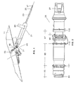
- Figure 1 shows a side view of a refueling boom according to the invention.
- Figure 2 shows a side view of the boom tip assembly according to the invention.
- Figure 3 show detailed views of the mechanical fuse included in the boom tip assembly according to the invention.
- Figure 4 shows a flow chart of a load alleviation method according to the invention.
- An aircraft refueling boom 21 is a telescoping beam fuel-tight unit attached to its forward end to the underside fuselage tail of an aircraft 11 by means of a mechanical articulation 41. lntegrally attached to the boom 21 are aerodynamic lift surfaces 29 called ruddevators which are used to aerodynamically control the position of the boom 21 in elevation and azimuth.
- the outer end portion 23 of the boom 21 is a telescoping section for inward and outward movement.
- Located on the distal end of the telescoping tube 23 is a boom tip assembly 25 and a nozzle 27.
- the receiver aircraft not shown, is equipped with an aerial refueling receptacle which engages with the nozzle 27 for the refueling operation.
- the boom 21 incorporates at is union with the tanker aircraft 11 a mechanical articulation 41 that provides it with two degrees of freedom and, in particular, a conical pivoting angular motion of the boom towards its pitch and roll axes as it will be explained in more detail below.
- the boom 21 is orientated towards the refueling space envelope via two ruddevators 29 (each one tied to the boom main structural tube tip via a rotary hinge) in a 'V' tail type configuration.
- the aerodynamically control forces to aim the boom arises by changing the incidence angle of the ruddevators with respect the free air stream.
- the relative positioning of each ruddevator incidence angle is achieved by an operator located in the tanker aircraft that can exercise remote control of the refueling operation via dedicated devices allocated on a control console.
- the telescoped beam 23 provides fuel passage from a fixed fuel line 31, connected to the tanker aircraft line 33 by means of a coupling 35 integrated with the mechanical articulation 41, to the nozzle 27.
- the boom operator located in the tanker aircraft 11, guides the boom 21 so as to line the boom nozzle 27 with the receiver aircraft receptacle.
- the boom operator extends the telescoping portion 23, so that the nozzle 27 engages the receptacle to complete the coupling which must be accomplished and maintained within a predetermined refueling envelope to avoid a disconnection.
- Loads during engagement and contact are transferred from the nozzle 27 to the boom 21 through a smart boom tip device 25 which attenuates, alleviates and limits such loads while maintaining a fuel tight passage through the boom 21 to the nozzle 27.
- the smart boom tip device 25 is attached to the boom 21 through a fuel tight flange 81.
- the forward most section of the smart boom tip device 25 consists of a loads sensing and concentrating device 83.
- Said device 83 includes pressure, flexion, torsion, compression and extension load sensing means as well as digitalization, consolidation, concentration and transmission means to send digital signals representing the information obtained by said sensing means to the boom control station (not shown).
- said sensing devices include strain gauge bridges.
- said sensing device include piezoelectric stress sensors.
- the digitalization, consolidation and concentration of load measurements obtained by said sensing means into a high integrity digital signal is based in the use of dual redundant microprocessors or micro computers and the usage of a dual redundant set of CAN, or a MIL1553 or an ARINC 429 digital buses. Said high integrity load data are digitally transmitted to the boom controi station where it is processed as explained in detail later.
- the middle section 85 of the smart boom tip 25 comprises fuel tight telescoping and swivel tubes and a set of shock absorbers that attenuates peak contact loads during tanker to receiver connection.
- the telescoping and swivel tubes accommodates for longitudinal and torsion degrees of freedom during contacts and to recover the original position after nozzle to receptacle disconnection.
- the shock absorbers utilize a mechanical elastic element like a set of friction springs. In another preferred embodiment the shock absorbers utilize a fluid or pneumatic energy dissipation device.
- the aft most section 87 of the smart boom tip device comprises a fuel tight tube which structure is calibrated as a mechanical fuse 99 that limits the longitudinal and radial forces, as well as flexion moments and protects the boom structure in a controlled fashion in the event of overloads assuring the safe separation of tanker and receiver aircraft.
- the mechanical fuse 99 utilizes at least one set of calibrated rivets 101 and at least one set of conveniently located weak links.
- the three main sections 83, 85 and 87 of the smart boom tip device are joined together through fuel tight flanged connections 111, 113
- the smart boom tip device in turn is joined to the nozzle 27 through a fuel tight flanged connection 115.
- the refueling boom according to this invention allows a method of boom load alleviation comprising the following operational steps:
- strain gauge signals are analyzed by the computer which provides automatic control to re-steer the boom back to a lower load position.
Abstract
Description
- The present invention relates generally to aircraft refueling booms and more specifically to a boom having a boom tip assembly that provides a load attenuation, limitation and alleviation during tanker/receiver contact and connection.
- An aircraft refueling boom is a beam fuel-tight unit attached to its forward end to a tanker aircraft having aerodynamic lift surfaces called ruddevators used to aerodynamically control the position of the boom in elevation and azimuth that provides a fuel passage from the tanker to the boom nozzle.
- The outer end portion of the boom is a telescoping section for inward and outward movement.
- The receiver aircraft is equipped with an aerial refueling receptacle which engages with the boom nozzle for the refueling operation.
- The boom operator located in the tanker aircraft guides the boom so as to line the boom nozzle with the receiver aircraft receptacle. When the boom nozzle is aligned with the receiver receptacle the boom operator extends the telescoping portion, so that the nozzle engages the receptacle to complete the coupling which must be accomplished and maintained within a predetermined refueling envelope to avoid a disconnection.
- During tanker to receiver contacts, mechanical contact loads are build up and stresses are placed on the boom as well as on the receiver. These stresses can result in boom or receptacle failure.
- A boom passive contact loads attenuation mechanism based on a recoil shock absorber on a boom in use is known. One disadvantage of this device is that it is not properly integrated in the boom.
- Once the refueling boom is connected to the receiver aircraft, known contact detection systems are based on coil signals installed on the nozzle. One disadvantage of this passive coil signals are the maintenance needs of the coil equipment. Another disadvantage is the potential for damage to the coil since the refueling boom adjacent to the coil installation commonly contacts the receiver aircraft.
- Known refueling booms do not provide for automatic boom load alleviation when the refueling boom is connected to the receiver aircraft. Stresses are placed on a boom due to the motion of the tanker as well as from the receiver that can result in boom failure. In these systems it is the responsibility of the boom operator to avoid boom deflections.
- A boom load alleviation system employing strain gauges is known. This load alleviation system relies on electrical feedback from the strain gauges to a computer onboard the aircraft which identifies a boom bending load. One disadvantage of this strain gauge type load alleviation system is the routing of the analog signals from the boom tip to the aircraft on board computer as well as the integrity of the raw signals.
- The present invention is intended to solve said disadvantages.
- In a first aspect, the present invention provides a refueling apparatus for interconnecting a tanker aircraft with a receiver aircraft in flight comprising a boom, joined to said tanker aircraft by means of a mechanical articulation, with an inner fuel conduit and a refueling nozzle at its distal end, having control means including a central computer station, being its tip region arranged by the assembly of a first module having load sensing means, a second module having load alleviation means and a third module, joined to the nozzle, having a mechanical fuse for allowing the safe separation of tanker and receiver aircraft in the event of overloads.
- Said first module also comprises means for converting the signals provided by said load sensing means into digital signals.
- The apparatus also comprises digital communication means between said first module and said central computer station.
- In a second aspect, the present invention provides a method of load alleviation in said refueling apparatus comprising the steps of:
- a) Acquiring load signals from load sensing means.
- b) Converting said load signals in digital signals.
- c) Processing said digital signals for obtaining and sending control signals to the ruddevator actuators for moving the ruddevators in order to minimize the loads on the boom.
- One advantage of this invention in that the modular assembly of the boom tip region provides a safer, more maintainable, and more durable refueling apparatus.
- Another advantage of this invention is that it provides a refueling apparatus with independent means for the detection of the contact with the receiver.
- Another advantage of this invention is that includes means for a high integrity load data consolidation to improve the safety and reliability of the load alleviation function.
- The foregoing objects and many of the attendant advantages of this invention will become more readily appreciated as the same becomes better understood by reference to the following detailed description when taken in conjunction with the accompanying drawings, wherein.
- Figure 1 shows a side view of a refueling boom according to the invention.
- Figure 2 shows a side view of the boom tip assembly according to the invention.
- Figure 3 show detailed views of the mechanical fuse included in the boom tip assembly according to the invention.
- Figure 4 shows a flow chart of a load alleviation method according to the invention.
- An aircraft refueling
boom 21 is a telescoping beam fuel-tight unit attached to its forward end to the underside fuselage tail of anaircraft 11 by means of amechanical articulation 41. lntegrally attached to theboom 21 areaerodynamic lift surfaces 29 called ruddevators which are used to aerodynamically control the position of theboom 21 in elevation and azimuth. - The
outer end portion 23 of theboom 21 is a telescoping section for inward and outward movement. Located on the distal end of thetelescoping tube 23 is aboom tip assembly 25 and anozzle 27. The receiver aircraft, not shown, is equipped with an aerial refueling receptacle which engages with thenozzle 27 for the refueling operation. - In order to satisfy the refueling space envelope requirements (with respect to the tanker aircraft reference axes), the
boom 21 incorporates at is union with the tanker aircraft 11 amechanical articulation 41 that provides it with two degrees of freedom and, in particular, a conical pivoting angular motion of the boom towards its pitch and roll axes as it will be explained in more detail below. - The
boom 21 is orientated towards the refueling space envelope via two ruddevators 29 (each one tied to the boom main structural tube tip via a rotary hinge) in a 'V' tail type configuration. The aerodynamically control forces to aim the boom arises by changing the incidence angle of the ruddevators with respect the free air stream. The relative positioning of each ruddevator incidence angle is achieved by an operator located in the tanker aircraft that can exercise remote control of the refueling operation via dedicated devices allocated on a control console. - The
telescoped beam 23 provides fuel passage from afixed fuel line 31, connected to thetanker aircraft line 33 by means of acoupling 35 integrated with themechanical articulation 41, to thenozzle 27. - The boom operator, not shown, located in the
tanker aircraft 11, guides theboom 21 so as to line theboom nozzle 27 with the receiver aircraft receptacle. When theboom nozzle 27 is dynamically aligned with the receiver receptacle the boom operator extends thetelescoping portion 23, so that thenozzle 27 engages the receptacle to complete the coupling which must be accomplished and maintained within a predetermined refueling envelope to avoid a disconnection. - Loads during engagement and contact are transferred from the
nozzle 27 to theboom 21 through a smartboom tip device 25 which attenuates, alleviates and limits such loads while maintaining a fuel tight passage through theboom 21 to thenozzle 27. - The smart
boom tip device 25 is attached to theboom 21 through a fueltight flange 81. The forward most section of the smartboom tip device 25 consists of a loads sensing and concentratingdevice 83. - Said
device 83 includes pressure, flexion, torsion, compression and extension load sensing means as well as digitalization, consolidation, concentration and transmission means to send digital signals representing the information obtained by said sensing means to the boom control station (not shown). - In a preferred embodiment said sensing devices include strain gauge bridges.
- In another preferred embodiment said sensing device include piezoelectric stress sensors.
- In a preferred embodiment the digitalization, consolidation and concentration of load measurements obtained by said sensing means into a high integrity digital signal is based in the use of dual redundant microprocessors or micro computers and the usage of a dual redundant set of CAN, or a MIL1553 or an ARINC 429 digital buses. Said high integrity load data are digitally transmitted to the boom controi station where it is processed as explained in detail later.
- The
middle section 85 of thesmart boom tip 25 comprises fuel tight telescoping and swivel tubes and a set of shock absorbers that attenuates peak contact loads during tanker to receiver connection. The telescoping and swivel tubes accommodates for longitudinal and torsion degrees of freedom during contacts and to recover the original position after nozzle to receptacle disconnection. - In one preferred embodiment of the invention, the shock absorbers utilize a mechanical elastic element like a set of friction springs. In another preferred embodiment the shock absorbers utilize a fluid or pneumatic energy dissipation device.
- The aft
most section 87 of the smart boom tip device comprises a fuel tight tube which structure is calibrated as amechanical fuse 99 that limits the longitudinal and radial forces, as well as flexion moments and protects the boom structure in a controlled fashion in the event of overloads assuring the safe separation of tanker and receiver aircraft. - In one preferred embodiment of the present invention the
mechanical fuse 99 utilizes at least one set of calibratedrivets 101 and at least one set of conveniently located weak links. - The three
main sections flanged connections nozzle 27 through a fuel tightflanged connection 115. - The refueling boom according to this invention allows a method of boom load alleviation comprising the following operational steps:
- In
step 121 sensor signals are acquired. - In
step 123 sensor signals are converted into digital signals. - In step 125 a computing process is performed to:
- Identify that the contact with the receiver aircraft is made, comparing the load levels with reference values stored in a computer memory.
- Calculate a control signal for repositioning the ruddevators in order to minimize the loads on the boom.
- In
step 127 said control signal is forwarded to the ruddevators actuators. In one preferred embodiment, an electro-mechanical actuator is used to reposition the flight control surfaces. In another preferred embodiment hydraulic control valves are used. - The strain gauge signals are analyzed by the computer which provides automatic control to re-steer the boom back to a lower load position.
- Although the present invention has been fully described in connection with preferred embodiments, it is evident that modifications may be introduced within the scope thereof, not considering this as limited by these embodiments, but by the contents of the following claims.
Claims (7)
- A refueling apparatus for interconnecting a tanker aircraft (11) with a receiver aircraft in flight comprising a boom (21) joined to said tanker aircraft (11) by means of a mechanical articulation (41), said boom (21) having an inner fuel conduit, a refueling nozzle (27) at its distal end and control means including a central computer station, characterized in that said boom (21) comprises at its tip region a first module (83) having load sensing means, a second module (85) having load alleviation means and a third module (87), joined to the nozzle (27), having a mechanical fuse (99) for allowing the safe separation of tanker and receiver aircraft in the event of overloads.
- A refueling apparatus according to claim 1 where said first module (83) also comprises means for converting the signals provided by said load sensing means into digital signals.
- A refueling apparatus according to claim 2 where said load sensing means include strain gauge bridges.
- A refueling apparatus according to claim 2 where said load sensing means include piezo-electrical sensors.
- A refueling apparatus according to claim 2 also comprising digital communication means between said first module (83) and said central computer station.
- A refueling apparatus according to claim 5 where said communication means include CAN, MIL 1553 or ARINC 429 digital buses.
- A method of load alleviation in a refueling apparatus for interconnecting a tanker aircraft (11) with a receiver aircraft in flight comprising a boom (21), joined to said tanker aircraft (11) by means of a mechanical articulation (41), said boom (21) including at its tip region a first module (83) having load sensing means, a second module (85) having load alleviation means, a third module (87), joined to the nozzle (27), having a mechanical fuse (99) for allowing the safe separation of tanker and receiver aircraft in the event of overloads, and control means including a central computer station, comprising the steps of:a) Acquiring load signals from load sensing means;b) Converting said load signals into digital signals;c) Processing said digital signals for obtaining and sending control signals to the ruddevator (29) actuators for moving the ruddevators in order to minimize the loads on the boom (21).
Priority Applications (4)
| Application Number | Priority Date | Filing Date | Title |
|---|---|---|---|
| DE602006004587T DE602006004587D1 (en) | 2006-08-29 | 2006-08-29 | Smart refueling jib tip device |
| AT06381034T ATE419178T1 (en) | 2006-08-29 | 2006-08-29 | INTELLIGENT REFUELING BOOM POINT DEVICE |
| EP06381034A EP1894840B1 (en) | 2006-08-29 | 2006-08-29 | Smart in-flight refuelling boom tip assembly |
| US11/542,631 US7954764B2 (en) | 2006-08-29 | 2006-10-03 | Smart boom tip assembly |
Applications Claiming Priority (1)
| Application Number | Priority Date | Filing Date | Title |
|---|---|---|---|
| EP06381034A EP1894840B1 (en) | 2006-08-29 | 2006-08-29 | Smart in-flight refuelling boom tip assembly |
Publications (2)
| Publication Number | Publication Date |
|---|---|
| EP1894840A1 true EP1894840A1 (en) | 2008-03-05 |
| EP1894840B1 EP1894840B1 (en) | 2008-12-31 |
Family
ID=37622116
Family Applications (1)
| Application Number | Title | Priority Date | Filing Date |
|---|---|---|---|
| EP06381034A Active EP1894840B1 (en) | 2006-08-29 | 2006-08-29 | Smart in-flight refuelling boom tip assembly |
Country Status (4)
| Country | Link |
|---|---|
| US (1) | US7954764B2 (en) |
| EP (1) | EP1894840B1 (en) |
| AT (1) | ATE419178T1 (en) |
| DE (1) | DE602006004587D1 (en) |
Cited By (4)
| Publication number | Priority date | Publication date | Assignee | Title |
|---|---|---|---|---|
| WO2010071643A1 (en) * | 2008-12-17 | 2010-06-24 | The Boeing Company | Automatically alleviating forces on a refueling boom |
| WO2012030444A1 (en) * | 2010-08-31 | 2012-03-08 | The Boeing Company | Aerial refueling boom nozzle with integral pressure regulation |
| EP2759478A1 (en) * | 2013-01-24 | 2014-07-30 | Israel Aerospace Industries Ltd. | Tip with nozzle load sensing and wireless communication functionality for refueling boom |
| EP3342716A1 (en) | 2016-12-28 | 2018-07-04 | Airbus Defence and Space SA | Aircraft refueling boom system with nozzle security means |
Families Citing this family (4)
| Publication number | Priority date | Publication date | Assignee | Title |
|---|---|---|---|---|
| EP2836431B1 (en) * | 2012-04-10 | 2020-05-06 | Israel Aerospace Industries Ltd. | A refueling airplane |
| US10654584B2 (en) * | 2016-08-13 | 2020-05-19 | Modern Technology Solutions, Inc. | Refueling system and method |
| US10913649B2 (en) | 2017-09-01 | 2021-02-09 | Eaton Intelligent Power Limited | Fluid nozzle with one or more sensors |
| US11104448B2 (en) | 2018-05-24 | 2021-08-31 | Eaton Intelligent Power Limited | Fluid nozzle |
Citations (3)
| Publication number | Priority date | Publication date | Assignee | Title |
|---|---|---|---|---|
| US4150803A (en) * | 1977-10-05 | 1979-04-24 | Fernandez Carlos P | Two axes controller |
| FR2569652A1 (en) * | 1984-09-04 | 1986-03-07 | Messerschmitt Boelkow Blohm | Tanker aircraft in-flight fuelling gear |
| US4586683A (en) * | 1979-03-12 | 1986-05-06 | Mcdonnell Douglas Corporation | Rolling aerial refueling boom |
Family Cites Families (8)
| Publication number | Priority date | Publication date | Assignee | Title |
|---|---|---|---|---|
| US2663523A (en) * | 1949-08-02 | 1953-12-22 | Boeing Co | Aircraft interconnecting mechanism |
| US3817560A (en) * | 1972-09-05 | 1974-06-18 | Dover Corp | Quick disconnect swivel coupling |
| US4408943A (en) * | 1981-02-27 | 1983-10-11 | Fmc Corporation | Ship-to-ship fluid transfer system |
| FR2638731B1 (en) * | 1988-11-09 | 1991-02-08 | Fmc Europe | METHOD FOR PROVIDING A DISCONNECTION BETWEEN A FLUID LOADING ARM AND A TANK, ONE OF WHICH IS CARRIED BY A VEHICLE IN THE EVENT OF AN UNEXPECTED DEPARTURE OF THE VEHICLE; FLUID LOADING ARM IMPLEMENTING THIS PROCESS; SAFETY DISCONNECTOR FOR ITS IMPLEMENTATION |
| US5785276A (en) * | 1995-12-22 | 1998-07-28 | The Boeing Company | Actuated roll axis aerial refueling boom |
| US6651933B1 (en) * | 2002-05-01 | 2003-11-25 | The Boeing Company | Boom load alleviation using visual means |
| US7021586B2 (en) * | 2004-02-19 | 2006-04-04 | The Boeing Company | Force feedback refueling system for unmanned aircraft |
| US7281687B2 (en) * | 2004-07-14 | 2007-10-16 | The Boeing Company | In-flight refueling system and method for facilitating emergency separation of in-flight refueling system components |
-
2006
- 2006-08-29 DE DE602006004587T patent/DE602006004587D1/en active Active
- 2006-08-29 AT AT06381034T patent/ATE419178T1/en not_active IP Right Cessation
- 2006-08-29 EP EP06381034A patent/EP1894840B1/en active Active
- 2006-10-03 US US11/542,631 patent/US7954764B2/en active Active
Patent Citations (3)
| Publication number | Priority date | Publication date | Assignee | Title |
|---|---|---|---|---|
| US4150803A (en) * | 1977-10-05 | 1979-04-24 | Fernandez Carlos P | Two axes controller |
| US4586683A (en) * | 1979-03-12 | 1986-05-06 | Mcdonnell Douglas Corporation | Rolling aerial refueling boom |
| FR2569652A1 (en) * | 1984-09-04 | 1986-03-07 | Messerschmitt Boelkow Blohm | Tanker aircraft in-flight fuelling gear |
Cited By (7)
| Publication number | Priority date | Publication date | Assignee | Title |
|---|---|---|---|---|
| WO2010071643A1 (en) * | 2008-12-17 | 2010-06-24 | The Boeing Company | Automatically alleviating forces on a refueling boom |
| JP2012512104A (en) * | 2008-12-17 | 2012-05-31 | ザ・ボーイング・カンパニー | Automatic reduction of the force applied to the refueling boom |
| WO2012030444A1 (en) * | 2010-08-31 | 2012-03-08 | The Boeing Company | Aerial refueling boom nozzle with integral pressure regulation |
| US8485474B2 (en) | 2010-08-31 | 2013-07-16 | The Boeing Company | Aerial refueling boom nozzle with integral pressure regulation |
| EP2759478A1 (en) * | 2013-01-24 | 2014-07-30 | Israel Aerospace Industries Ltd. | Tip with nozzle load sensing and wireless communication functionality for refueling boom |
| US9840336B2 (en) | 2013-01-24 | 2017-12-12 | Israel Aerospace Industries Ltd. | Tip with nozzle load sensing and wireless communication functionality for refueling boom |
| EP3342716A1 (en) | 2016-12-28 | 2018-07-04 | Airbus Defence and Space SA | Aircraft refueling boom system with nozzle security means |
Also Published As
| Publication number | Publication date |
|---|---|
| EP1894840B1 (en) | 2008-12-31 |
| US7954764B2 (en) | 2011-06-07 |
| DE602006004587D1 (en) | 2009-02-12 |
| US20100327116A1 (en) | 2010-12-30 |
| ATE419178T1 (en) | 2009-01-15 |
Similar Documents
| Publication | Publication Date | Title |
|---|---|---|
| EP1894840B1 (en) | Smart in-flight refuelling boom tip assembly | |
| EP2759478B1 (en) | Tip with nozzle load sensing and wireless communication functionality for refueling boom | |
| US8033500B1 (en) | Actuator load path monitoring system | |
| EP2625103B1 (en) | Actuation system for an adjustable aircraft flap and method for reconfiguring the actuation system | |
| US10232960B2 (en) | Manipulation of a satellite in space | |
| US8868261B2 (en) | Monitoring device for an actuation system of an aircraft, actuation system and method for reconfiguring the actuation system | |
| US8191824B2 (en) | Integrated load sensing system | |
| EP2035275B1 (en) | Adjusting device for adjusting a high-lift flap and airfoil wing comprising such an adjusting device | |
| EP1878658A2 (en) | Aircraft stabilizer actuator | |
| US20130181089A1 (en) | Adjustment system of an aeroplane with an adjustable flap | |
| EP2783135B1 (en) | An electromechanical actuator for an aircraft control surface, and an aircraft provided with such an actuator | |
| EP1754660B1 (en) | Flexible air refueling boom extendable tube | |
| CN112351937A (en) | Control surface element inclination and/or loss detection system | |
| US11312479B2 (en) | Force application device for a control stick of an aircraft | |
| US5701801A (en) | Mechanically redundant actuator assembly | |
| US9511852B2 (en) | Device for coupling an actuator for controlling the landing gear of an aircraft | |
| US6830223B1 (en) | Force sensor rod | |
| EP2447160B1 (en) | Adaptable boom for in-flight refuelling system | |
| EP2370317B1 (en) | Automatically alleviating forces on a refueling boom | |
| EP1916186B1 (en) | Refueling boom with a fail-safe roll-pitch device | |
| US9046449B2 (en) | Measurement device for the measurement of forces in structural components | |
| US20180178924A1 (en) | Aircraft refueling boom system with nozzle security means | |
| US11708178B2 (en) | Monitoring system for an assembly having a kinematic coupling | |
| KR101885663B1 (en) | Fly-by-wire flight control system with backup mechanical flight control system | |
| JPS6215200A (en) | Aviation electronic control system |
Legal Events
| Date | Code | Title | Description |
|---|---|---|---|
| PUAI | Public reference made under article 153(3) epc to a published international application that has entered the european phase |
Free format text: ORIGINAL CODE: 0009012 |
|
| 17P | Request for examination filed |
Effective date: 20070222 |
|
| AK | Designated contracting states |
Kind code of ref document: A1 Designated state(s): AT BE BG CH CY CZ DE DK EE ES FI FR GB GR HU IE IS IT LI LT LU LV MC NL PL PT RO SE SI SK TR |
|
| AX | Request for extension of the european patent |
Extension state: AL BA HR MK YU |
|
| GRAP | Despatch of communication of intention to grant a patent |
Free format text: ORIGINAL CODE: EPIDOSNIGR1 |
|
| GRAS | Grant fee paid |
Free format text: ORIGINAL CODE: EPIDOSNIGR3 |
|
| AKX | Designation fees paid |
Designated state(s): AT BE BG CH CY CZ DE DK EE ES FI FR GB GR HU IE IS IT LI LT LU LV MC NL PL PT RO SE SI SK TR |
|
| GRAA | (expected) grant |
Free format text: ORIGINAL CODE: 0009210 |
|
| AK | Designated contracting states |
Kind code of ref document: B1 Designated state(s): AT BE BG CH CY CZ DE DK EE ES FI FR GB GR HU IE IS IT LI LT LU LV MC NL PL PT RO SE SI SK TR |
|
| REG | Reference to a national code |
Ref country code: GB Ref legal event code: FG4D Ref country code: CH Ref legal event code: EP |
|
| REF | Corresponds to: |
Ref document number: 602006004587 Country of ref document: DE Date of ref document: 20090212 Kind code of ref document: P |
|
| REG | Reference to a national code |
Ref country code: IE Ref legal event code: FG4D |
|
| PG25 | Lapsed in a contracting state [announced via postgrant information from national office to epo] |
Ref country code: SI Free format text: LAPSE BECAUSE OF FAILURE TO SUBMIT A TRANSLATION OF THE DESCRIPTION OR TO PAY THE FEE WITHIN THE PRESCRIBED TIME-LIMIT Effective date: 20081231 Ref country code: PL Free format text: LAPSE BECAUSE OF FAILURE TO SUBMIT A TRANSLATION OF THE DESCRIPTION OR TO PAY THE FEE WITHIN THE PRESCRIBED TIME-LIMIT Effective date: 20081231 Ref country code: LV Free format text: LAPSE BECAUSE OF FAILURE TO SUBMIT A TRANSLATION OF THE DESCRIPTION OR TO PAY THE FEE WITHIN THE PRESCRIBED TIME-LIMIT Effective date: 20081231 |
|
| PG25 | Lapsed in a contracting state [announced via postgrant information from national office to epo] |
Ref country code: LT Free format text: LAPSE BECAUSE OF FAILURE TO SUBMIT A TRANSLATION OF THE DESCRIPTION OR TO PAY THE FEE WITHIN THE PRESCRIBED TIME-LIMIT Effective date: 20081231 Ref country code: RO Free format text: LAPSE BECAUSE OF FAILURE TO SUBMIT A TRANSLATION OF THE DESCRIPTION OR TO PAY THE FEE WITHIN THE PRESCRIBED TIME-LIMIT Effective date: 20081231 Ref country code: BE Free format text: LAPSE BECAUSE OF FAILURE TO SUBMIT A TRANSLATION OF THE DESCRIPTION OR TO PAY THE FEE WITHIN THE PRESCRIBED TIME-LIMIT Effective date: 20081231 Ref country code: ES Free format text: LAPSE BECAUSE OF FAILURE TO SUBMIT A TRANSLATION OF THE DESCRIPTION OR TO PAY THE FEE WITHIN THE PRESCRIBED TIME-LIMIT Effective date: 20090411 Ref country code: EE Free format text: LAPSE BECAUSE OF FAILURE TO SUBMIT A TRANSLATION OF THE DESCRIPTION OR TO PAY THE FEE WITHIN THE PRESCRIBED TIME-LIMIT Effective date: 20081231 |
|
| PG25 | Lapsed in a contracting state [announced via postgrant information from national office to epo] |
Ref country code: IS Free format text: LAPSE BECAUSE OF FAILURE TO SUBMIT A TRANSLATION OF THE DESCRIPTION OR TO PAY THE FEE WITHIN THE PRESCRIBED TIME-LIMIT Effective date: 20090430 Ref country code: PT Free format text: LAPSE BECAUSE OF FAILURE TO SUBMIT A TRANSLATION OF THE DESCRIPTION OR TO PAY THE FEE WITHIN THE PRESCRIBED TIME-LIMIT Effective date: 20090601 Ref country code: SE Free format text: LAPSE BECAUSE OF FAILURE TO SUBMIT A TRANSLATION OF THE DESCRIPTION OR TO PAY THE FEE WITHIN THE PRESCRIBED TIME-LIMIT Effective date: 20090331 Ref country code: CZ Free format text: LAPSE BECAUSE OF FAILURE TO SUBMIT A TRANSLATION OF THE DESCRIPTION OR TO PAY THE FEE WITHIN THE PRESCRIBED TIME-LIMIT Effective date: 20081231 Ref country code: AT Free format text: LAPSE BECAUSE OF FAILURE TO SUBMIT A TRANSLATION OF THE DESCRIPTION OR TO PAY THE FEE WITHIN THE PRESCRIBED TIME-LIMIT Effective date: 20081231 |
|
| PG25 | Lapsed in a contracting state [announced via postgrant information from national office to epo] |
Ref country code: SK Free format text: LAPSE BECAUSE OF FAILURE TO SUBMIT A TRANSLATION OF THE DESCRIPTION OR TO PAY THE FEE WITHIN THE PRESCRIBED TIME-LIMIT Effective date: 20081231 |
|
| PG25 | Lapsed in a contracting state [announced via postgrant information from national office to epo] |
Ref country code: DK Free format text: LAPSE BECAUSE OF FAILURE TO SUBMIT A TRANSLATION OF THE DESCRIPTION OR TO PAY THE FEE WITHIN THE PRESCRIBED TIME-LIMIT Effective date: 20081231 |
|
| PLBE | No opposition filed within time limit |
Free format text: ORIGINAL CODE: 0009261 |
|
| STAA | Information on the status of an ep patent application or granted ep patent |
Free format text: STATUS: NO OPPOSITION FILED WITHIN TIME LIMIT |
|
| 26N | No opposition filed |
Effective date: 20091001 |
|
| PG25 | Lapsed in a contracting state [announced via postgrant information from national office to epo] |
Ref country code: BG Free format text: LAPSE BECAUSE OF FAILURE TO SUBMIT A TRANSLATION OF THE DESCRIPTION OR TO PAY THE FEE WITHIN THE PRESCRIBED TIME-LIMIT Effective date: 20090331 |
|
| PG25 | Lapsed in a contracting state [announced via postgrant information from national office to epo] |
Ref country code: MC Free format text: LAPSE BECAUSE OF NON-PAYMENT OF DUE FEES Effective date: 20090831 |
|
| REG | Reference to a national code |
Ref country code: IE Ref legal event code: MM4A |
|
| PG25 | Lapsed in a contracting state [announced via postgrant information from national office to epo] |
Ref country code: IE Free format text: LAPSE BECAUSE OF NON-PAYMENT OF DUE FEES Effective date: 20090829 |
|
| PG25 | Lapsed in a contracting state [announced via postgrant information from national office to epo] |
Ref country code: GR Free format text: LAPSE BECAUSE OF FAILURE TO SUBMIT A TRANSLATION OF THE DESCRIPTION OR TO PAY THE FEE WITHIN THE PRESCRIBED TIME-LIMIT Effective date: 20090401 |
|
| REG | Reference to a national code |
Ref country code: CH Ref legal event code: PL |
|
| PG25 | Lapsed in a contracting state [announced via postgrant information from national office to epo] |
Ref country code: LI Free format text: LAPSE BECAUSE OF NON-PAYMENT OF DUE FEES Effective date: 20100831 Ref country code: CH Free format text: LAPSE BECAUSE OF NON-PAYMENT OF DUE FEES Effective date: 20100831 Ref country code: LU Free format text: LAPSE BECAUSE OF NON-PAYMENT OF DUE FEES Effective date: 20090829 |
|
| PG25 | Lapsed in a contracting state [announced via postgrant information from national office to epo] |
Ref country code: HU Free format text: LAPSE BECAUSE OF FAILURE TO SUBMIT A TRANSLATION OF THE DESCRIPTION OR TO PAY THE FEE WITHIN THE PRESCRIBED TIME-LIMIT Effective date: 20090701 |
|
| PG25 | Lapsed in a contracting state [announced via postgrant information from national office to epo] |
Ref country code: CY Free format text: LAPSE BECAUSE OF FAILURE TO SUBMIT A TRANSLATION OF THE DESCRIPTION OR TO PAY THE FEE WITHIN THE PRESCRIBED TIME-LIMIT Effective date: 20081231 |
|
| REG | Reference to a national code |
Ref country code: FR Ref legal event code: PLFP Year of fee payment: 10 |
|
| REG | Reference to a national code |
Ref country code: NL Ref legal event code: TD Effective date: 20150901 |
|
| REG | Reference to a national code |
Ref country code: DE Ref legal event code: R082 Ref document number: 602006004587 Country of ref document: DE Representative=s name: DENNEMEYER & ASSOCIATES S.A., DE Ref country code: DE Ref legal event code: R081 Ref document number: 602006004587 Country of ref document: DE Owner name: AIRBUS DEFENCE AND SPACE SA, GETAFE, ES Free format text: FORMER OWNER: EADS CONSTRUCCIONES AERONAUTICAS S.A., MADRID, ES |
|
| REG | Reference to a national code |
Ref country code: FR Ref legal event code: CD Owner name: AIRBUS DEFENCE AND SPACE SA, ES Effective date: 20151118 Ref country code: FR Ref legal event code: CA Effective date: 20151118 |
|
| REG | Reference to a national code |
Ref country code: FR Ref legal event code: PLFP Year of fee payment: 11 |
|
| REG | Reference to a national code |
Ref country code: FR Ref legal event code: PLFP Year of fee payment: 12 |
|
| REG | Reference to a national code |
Ref country code: FR Ref legal event code: PLFP Year of fee payment: 13 |
|
| PGFP | Annual fee paid to national office [announced via postgrant information from national office to epo] |
Ref country code: NL Payment date: 20190821 Year of fee payment: 14 |
|
| PGFP | Annual fee paid to national office [announced via postgrant information from national office to epo] |
Ref country code: FR Payment date: 20190822 Year of fee payment: 14 Ref country code: FI Payment date: 20190822 Year of fee payment: 14 Ref country code: IT Payment date: 20190829 Year of fee payment: 14 Ref country code: TR Payment date: 20190820 Year of fee payment: 14 Ref country code: DE Payment date: 20190822 Year of fee payment: 14 |
|
| REG | Reference to a national code |
Ref country code: DE Ref legal event code: R119 Ref document number: 602006004587 Country of ref document: DE |
|
| REG | Reference to a national code |
Ref country code: FI Ref legal event code: MAE |
|
| REG | Reference to a national code |
Ref country code: NL Ref legal event code: MM Effective date: 20200901 |
|
| PG25 | Lapsed in a contracting state [announced via postgrant information from national office to epo] |
Ref country code: FI Free format text: LAPSE BECAUSE OF NON-PAYMENT OF DUE FEES Effective date: 20200829 |
|
| PG25 | Lapsed in a contracting state [announced via postgrant information from national office to epo] |
Ref country code: FR Free format text: LAPSE BECAUSE OF NON-PAYMENT OF DUE FEES Effective date: 20200831 Ref country code: DE Free format text: LAPSE BECAUSE OF NON-PAYMENT OF DUE FEES Effective date: 20210302 |
|
| PG25 | Lapsed in a contracting state [announced via postgrant information from national office to epo] |
Ref country code: NL Free format text: LAPSE BECAUSE OF NON-PAYMENT OF DUE FEES Effective date: 20200901 |
|
| PG25 | Lapsed in a contracting state [announced via postgrant information from national office to epo] |
Ref country code: IT Free format text: LAPSE BECAUSE OF NON-PAYMENT OF DUE FEES Effective date: 20200829 |
|
| PG25 | Lapsed in a contracting state [announced via postgrant information from national office to epo] |
Ref country code: TR Free format text: LAPSE BECAUSE OF NON-PAYMENT OF DUE FEES Effective date: 20200829 |
|
| PGFP | Annual fee paid to national office [announced via postgrant information from national office to epo] |
Ref country code: GB Payment date: 20230822 Year of fee payment: 18 |