EP1900485A2 - Ergonomic handle - Google Patents
Ergonomic handle Download PDFInfo
- Publication number
- EP1900485A2 EP1900485A2 EP07075802A EP07075802A EP1900485A2 EP 1900485 A2 EP1900485 A2 EP 1900485A2 EP 07075802 A EP07075802 A EP 07075802A EP 07075802 A EP07075802 A EP 07075802A EP 1900485 A2 EP1900485 A2 EP 1900485A2
- Authority
- EP
- European Patent Office
- Prior art keywords
- tool handle
- end portion
- side surfaces
- contoured side
- ergonomic tool
- Prior art date
- Legal status (The legal status is an assumption and is not a legal conclusion. Google has not performed a legal analysis and makes no representation as to the accuracy of the status listed.)
- Withdrawn
Links
Images


Classifications
-
- B—PERFORMING OPERATIONS; TRANSPORTING
- B25—HAND TOOLS; PORTABLE POWER-DRIVEN TOOLS; MANIPULATORS
- B25G—HANDLES FOR HAND IMPLEMENTS
- B25G1/00—Handle constructions
- B25G1/10—Handle constructions characterised by material or shape
- B25G1/102—Handle constructions characterised by material or shape the shape being specially adapted to facilitate handling or improve grip
Definitions
- the present invention relates generally to handles on tools. More particularly, the present invention relates to an ergonomic handle for a tool.
- Tool handles can be broadly divided into the Tee shape or the axial shape.
- the axial shape usually aligns with the axis of the tool or the axis about which the work is performed. Handles of the axial or cylindrical shape are often extensions of a tool that must be rotated during the performance of its task.
- a typical rotational task is one of driving a threaded screw into a substrate.
- the handle is rotated, twisting the tool shaft and turning the fastener in the desired direction.
- fasteners When fasteners are driven with a hand tool they typically manifest increasing resistance to rotation as they penetrate the substrate. This resistance to turning may cause the tool handle to slip in the hand.
- the typical response to this condition is to increase hand pressure on the handle. This extra exertion of the hand muscles redirects both the attention of the tool user and the effort of the users hand away from the task and back to the handle grip. Furthermore, the hand fatigues more rapidly further suffering the task.
- Handles on tools that are used in certain medical procedures such as orthopedics require that the amount of attention devoted to the containment or control of a tool be minimal. Full attention must be focused on the performance of the task such as driving a screw into a bone or fastening a plate to a vertebra. The tool must perform as an extension to the hand not a hindrance.
- U.S. Patents No. 6,148,701 and No. 5,551,323 Examples of prior art handle designs are shown in U.S. Patents No. 6,148,701 and No. 5,551,323 .
- U.S. Patent No. 5,551,323 shows a handle that is relatively of square cross-section. However a square cross-section fails to properly conform to the human hand and fails to adequately transfer the grip force vectors from the hand through the handle and ultimately to the object to be rotated or actuated by the tool.
- U.S. Patent No. 6,148,701 shows a three-sided tool handle that is an improvement on the handle shown in U.S. Patent No. 5,551,323 .
- U.S. Patent No. 6,148,701 further includes a handle that twists along its longitudinal length, so as to better conform to the grip of a human hand.
- a further prior art design patent No. D523,724 shows a three-sided t001 handle with a cross-section that is made of three lobed protrusions. While the lobes may serve to provide some traction with the human hand grip, the entire shape of the handle in D523,724 does not lend itself to an adequate application of grip force, furthermore, when viewed in cross-section the handle is virtually round and by itself cannot prevent inadvertent rotation in the hand. Only extreme hand pressure can improve the grip on a round tool handle.
- An ergonomic t001 handle will conform to the bone under structure (bony architecture) of the hand, forming a natural fit between bones, flesh and the t001 handle. In this a manner an ergonomic or natural fit is created between the hand and the handle that prohibits the handle from rotating in the hand unless the hand is opened to release the handle.
- an apparatus in some embodiments provides for an ergonomic tool handle to better conform to the human grip, providing both the capability for enhanced precision and power through a uniquely shaped and contoured gripping configuration defined by the intersection of three side surfaces to substantially form a circular or Realeaux triangle in cross-section.
- an ergonimic tool handle having a body defining a central axis and having a distal end portion and a proximal end portion.
- the body includes three contoured side surfaces radially offset from the central axis and extending from the proximal end portion to the distal end portion.
- the three contoured side surfaces define a cross-section for the body shaped substantially as a Reuleaux triangle centered on the central axis.
- an ergonomic tool handle in accordance with another aspect of the present invention, includes a body centered about a rotational axis having opposite proximal and distal end portions.
- the body includes an outer gripping surface between the end portions defined by three contoured side surfaces having a convex radial and longitudinal shape with respect to the rotational axis.
- the body defines a longitudinal cross-section bounded by the three contoured side surfaces and shaped substantially as a circular triangle having three apices.
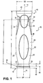
- FIG. 1 is a side longitudinal view illustrating an ergonmic handle for a hand tool according to a preferred embodiment of the invention.
- FIG. 2 is a plan view from the proximal end portion of the ergonomic handle shown in FIG. 1.
- FIG. 3 shows an example of a Reuleaux triangle.
- An embodiment in accordance with the present invention provides an ergonomic tool handle to provide an improved gripping surface so as to transmit greater power and precision from the human hand actuating the handle to the object being actuated by the tool.
- the present invention includes a tool handle having a uniquely shaped and contoured gripping surface defined by the intersection of three side surfaces to substantially form a circular or Reuleaux triangle in at least one cross-sectional area along the longitudinal span of the handle.
- the crux of the present invention is that the tool handle comfortably conforms to the human anatomy and permits more user attention and strength to be dedicated to actuating an object with the handle, rather than to the holding of the handle itself.
- FIG. 1 is a side longitudinal view illustrating an ergonomic handle 10 for a hand tool according to a preferred embodiment of the invention.
- the handle 10 includes a body 12 defining a longitudinal central axis 14.
- the axis 14 is substantially centered along a longitudinal axis of rotation for the body 12.
- the handle body 12 defines distal end portion 16 and a proximal end portion 18.
- a shaft can extend from the distal end portion 16 to an operative end of the tool (not shown) which can be used to actuate an object such as a screw.
- Additional sub-assemblies for actuating objects such as a ratchet mechanism and other devices well-known in the art, can be coupled to the distal end portion 16.
- FIG. 2 is a plan view from the proximal end portion 18 of the ergonomic handle 10 shown in FIG.1.
- the body 12 defines three contoured side surfaces 20 radially offset from the central axis 14 (shown as cross X within a circle in FIG. 2).
- the side surfaces 20 are contoured and extend from the proximal end portion 18 to the distal end portion 16.
- An additional set of depressions 23 are defined proximate the distal end portion 16 along the contoured side surfaces 20.
- a further set of depressions 24 are defined proximate the distal end portion 16 along a portion of the longitudinal edges 26 which are formed at the intersection of any two of the side surfaces 20.
- the three contoured side surfaces 20 intersect to define three longitudinal edges 26.
- the edges 26 can each define the apex of a cross-sectional shape for the body 12. These points can be the apices of a cross-sectional shape which can generally be described to fit inside the outline of a circular triangle.
- the three contoured side surfaces 20 together define at least one cross-section for the body shaped substantially as a circular triangle centered on the central axis 14.
- a "circular triangle” is a shape made of three circular arcs which together form the perimeter of a closed shape, which can resemble a triangle in the broadest sense.
- a Reuleaux triangle is formed, which is a polygon that is a curve of constant width - that is, a curve in which all diameters are the same length.
- the Reuleaux triangle is named after Franz Reuleaux, a 19th-century German engineer.
- the Reuleaux triangle is the simplest nontrivial example of a curve of constant width - a curve in which the distance between two opposite parallel tangent lines to its boundary is the same, regardless of the direction of those two parallel lines.
- the trivial example would be a circle.
- FIG. 3 shows an example of a Reuleaux triangle "R" having a diameter "d” which also forms the sides of an equilateral triangle circumscribed by the Reuleaux triangle R.
- the "width" of the Reuleaux triangle R is defined by two parallel lines P1 and P2 which have the same separation distance d regardless of their orientation when enclosing the Reuleaux triangle R.
- the Reuleaux triangle R is traced out by circular arcs having radius d centered on each of the apices A1, A2, and A3 of the Reuleaux triangle R.
- at least some portion of the body 12 has a longitudinal cross-sectional shape (i.e. a cross-section perpendicular to the central axis 14) which broadly approximates a Reuleaux triangle.
- the width of the body across such a cross-section is labeled as D in FIG. 2.
- the body 12 can also have an overall length L.
- the width D of the body 12 can be 1.435 inches, and the length L can be 5.050 inches.
- Such dimensions are only exemplary, and can be altered depending on the shape of the handle desired and the size of the human hand intended to grip the handle.
- the ratio of the length L over the width D can be within a range of 3.3 to 3.7. In an exemplary embodiment, said ratio can be approximately equal to 3.5.
- the body 12 also defines a radial lip 30 defined on the proximal end portion 18, thereby forming and defining a first neck 32 proximate the proximal end portion 18 between the radial lip 30 and the three contoured side surfaces 20.
- the body 12 and contoured side surfaces 20 can also each define a second neck 34 proximate the distal end portion 16.
- the first neck 32 and second neck 34 can define a grip length "G" which can vary according to the size of the hand. However a ratio of the grip length G over the body width D can be in the range of 2.5 to 2.9. In an exemplary embodiment, said ratio can be approximately equal to 2.7.
- the distal end portion 16 of the body 12 can span a distal end surface 40 which can have a width "SD" as shown in FIG. 1.
- said width SD can be approximately equal to 1.440 inches.
- the proximal end portion 18 can also span a proximal end surface 42 which can have a width "SP" as shown in FIG. 1.
- said width SP can be approximately equal to 1.125 inches.
- the radius of curvature of lip 30 can be approximately equal to 0.1 inches, while the proximal half-span 44 of neck 32 in longitudinal direction can, in an exemplary embodiment, can be approximately equal to 0.2 inches.
- the thickness 46 of the lip can be approximately equal to 0.150 inches.
- the configuration of the handle 12 conforms to the anatomical architecture of the human hand. It provides for the various grip positions which can be commonly labeled as the "precision” grip and the “power” grip.
- the pulp surfaces of the thumb and fingers are placed opposite each other. The fingers are flexed at the metacarpophalangeal joints, where the thumb extends straight from the hand.
- the combined fingers form one jaw of the clamp with the palm as the other jaw, where the thumb is curled around the handle with the tip of the thumb facing the fingertips.
- the tool handle of the present invention provides an arch defined by one of longitudinal edges 26 for the fingers to fold over, and flat land area largely defined by the surface of contoured side surfaces 20 and central depressions 22 for the ball of the thumb (also known as the Thenar muscle), providing the most anatomical anti-slip grip.
- the three side surfaces 20 that form the three sides of the handle triangle provide a surface to accommodate the thumb muscle and palm.
- the hand does not have to squeeze the handle 10 to prevent rotation of the handle relative to the hand. Instead the hand bones conform to the handle shape. This reduces hand fatigue and provides a user more energy for utilizing the handle and tool attached thereto.
Abstract
Description
- The present invention relates generally to handles on tools. More particularly, the present invention relates to an ergonomic handle for a tool.
- Tool handles can be broadly divided into the Tee shape or the axial shape. The axial shape usually aligns with the axis of the tool or the axis about which the work is performed. Handles of the axial or cylindrical shape are often extensions of a tool that must be rotated during the performance of its task.
- A typical rotational task is one of driving a threaded screw into a substrate. The handle is rotated, twisting the tool shaft and turning the fastener in the desired direction. When fasteners are driven with a hand tool they typically manifest increasing resistance to rotation as they penetrate the substrate. This resistance to turning may cause the tool handle to slip in the hand. The typical response to this condition is to increase hand pressure on the handle. This extra exertion of the hand muscles redirects both the attention of the tool user and the effort of the users hand away from the task and back to the handle grip. Furthermore, the hand fatigues more rapidly further suffering the task.
- Most handle designs and configurations known in the art are not shaped to properly conform to the human hand or augment the tool's use or purpose. The known tool handles instead follow a historic lineage of geometric shapes with slight variation and color changes. The variety of handle designs available today would indicate that the hand must adapt to the handle shape rather than the handle conforming to the hand shape.
- Most of the handle shapes considered state-of-the-art at this time can be classified as circular or close to circular when viewed in cross section. When the hand grips these shapes the fleshy pads of the fingers fill the space between the finger bones and the handle. In no instance does the bony architecture of the hand interact with a similar plane or the handle. As a result, the only resistance to inadvertent rotation or shear of the handle in the hand is the tension applied to the handle, through the flesh of the fingers, by the pressure of the hand.
- The greater the handle resistance to rotation, the greater the pressure the hand must apply to the handle. This is fatiguing to the hand and subtractive to the task.
- Handles on tools that are used in certain medical procedures such as orthopedics require that the amount of attention devoted to the containment or control of a tool be minimal. Full attention must be focused on the performance of the task such as driving a screw into a bone or fastening a plate to a vertebra. The tool must perform as an extension to the hand not a hindrance.
- Examples of prior art handle designs are shown in
U.S. Patents No. 6,148,701 andNo. 5,551,323 .U.S. Patent No. 5,551,323 shows a handle that is relatively of square cross-section. However a square cross-section fails to properly conform to the human hand and fails to adequately transfer the grip force vectors from the hand through the handle and ultimately to the object to be rotated or actuated by the tool.U.S. Patent No. 6,148,701 shows a three-sided tool handle that is an improvement on the handle shown inU.S. Patent No. 5,551,323 .U.S. Patent No. 6,148,701 further includes a handle that twists along its longitudinal length, so as to better conform to the grip of a human hand. However this patent shows a triangular cross-section that is relatively flat and not rounded, which again fails to properly conform to the p p force vectors for a human hand. A further prior art design patent No. D523,724 shows a three-sided t001 handle with a cross-section that is made of three lobed protrusions. While the lobes may serve to provide some traction with the human hand grip, the entire shape of the handle in D523,724 does not lend itself to an adequate application of grip force, furthermore, when viewed in cross-section the handle is virtually round and by itself cannot prevent inadvertent rotation in the hand. Only extreme hand pressure can improve the grip on a round tool handle. - An ergonomic t001 handle will conform to the bone under structure (bony architecture) of the hand, forming a natural fit between bones, flesh and the t001 handle. In this a manner an ergonomic or natural fit is created between the hand and the handle that prohibits the handle from rotating in the hand unless the hand is opened to release the handle.
- Accordingly, it is desirable to provide a device that comfortably conforms to the human anatomy and permits more user attention and strength to be dedicated to the task or intended purpose of the tool rather than first holding the handle and then performing the task.
- The foregoing needs are met, to a great extent, by the present invention, wherein in one aspect an apparatus is provided that in some embodiments provides for an ergonomic tool handle to better conform to the human grip, providing both the capability for enhanced precision and power through a uniquely shaped and contoured gripping configuration defined by the intersection of three side surfaces to substantially form a circular or Realeaux triangle in cross-section.
- In accordance with one aspect of the present invention, an ergonimic tool handle is provided, having a body defining a central axis and having a distal end portion and a proximal end portion. The body includes three contoured side surfaces radially offset from the central axis and extending from the proximal end portion to the distal end portion. The three contoured side surfaces define a cross-section for the body shaped substantially as a Reuleaux triangle centered on the central axis.
- In accordance with another aspect of the present invention, an ergonomic tool handle includes a body centered about a rotational axis having opposite proximal and distal end portions. The body includes an outer gripping surface between the end portions defined by three contoured side surfaces having a convex radial and longitudinal shape with respect to the rotational axis. The body defines a longitudinal cross-section bounded by the three contoured side surfaces and shaped substantially as a circular triangle having three apices.
- There has thus been outlined, rather broadly, certain embodiments of the invention in order that the detailed description thereof herein may be better understood, and in order that the present contribution to the art may be better appreciated. There are, of course, additional embodiments of the invention that will be described below and which will form the subject matter of the claims appended hereto.
- In this respect, before explaining at least one embodiment of the invention in detail, it is to be understood that the invention is not limited in its application to the details of construction and to the arrangements of the components set forth in the following description or illustrated in the drawings. The invention is capable of embodiments in addition to those described and of being practiced and carried out in various ways. Also, it is to be understood that the phraseology and terminology employed herein, as well as the abstract, are for the purpose of description and should not be regarded as limiting.
- As such, those skilled in the art will appreciate that the conception upon which this disclosure is based may readily be utilized as a basis for the designing of other structures, methods and systems for carrying out the several purposes of the present invention. It is important, therefore, that the claims be regarded as including such equivalent constructions insofar as they do not depart from the spirit and scope of the present invention.
- FIG. 1 is a side longitudinal view illustrating an ergonmic handle for a hand tool according to a preferred embodiment of the invention.
- FIG. 2 is a plan view from the proximal end portion of the ergonomic handle shown in FIG. 1.
- FIG. 3 shows an example of a Reuleaux triangle.
- The invention will now be described with reference to the drawing figures, in which like reference numerals refer to like parts throughout. An embodiment in accordance with the present invention provides an ergonomic tool handle to provide an improved gripping surface so as to transmit greater power and precision from the human hand actuating the handle to the object being actuated by the tool. The present invention includes a tool handle having a uniquely shaped and contoured gripping surface defined by the intersection of three side surfaces to substantially form a circular or Reuleaux triangle in at least one cross-sectional area along the longitudinal span of the handle. The crux of the present invention is that the tool handle comfortably conforms to the human anatomy and permits more user attention and strength to be dedicated to actuating an object with the handle, rather than to the holding of the handle itself.
- An embodiment of the present inventive apparatus is illustrated in FIG.1. FIG. 1 is a side longitudinal view illustrating an
ergonomic handle 10 for a hand tool according to a preferred embodiment of the invention. Thehandle 10 includes abody 12 defining a longitudinalcentral axis 14. Theaxis 14 is substantially centered along a longitudinal axis of rotation for thebody 12. Thehandle body 12 definesdistal end portion 16 and aproximal end portion 18. A shaft (not shown) can extend from thedistal end portion 16 to an operative end of the tool (not shown) which can be used to actuate an object such as a screw. Additional sub-assemblies for actuating objects, such as a ratchet mechanism and other devices well-known in the art, can be coupled to thedistal end portion 16. - FIG. 2 is a plan view from the
proximal end portion 18 of theergonomic handle 10 shown in FIG.1. Thebody 12 defines three contoured side surfaces 20 radially offset from the central axis 14 (shown as cross X within a circle in FIG. 2). The side surfaces 20 are contoured and extend from theproximal end portion 18 to thedistal end portion 16. Within a central portion of eachside surface 20, there is adepression 22, whichdepression 22 is positioned more closely to theproximal end portion 18 rather than thedistal end portion 16. An additional set ofdepressions 23 are defined proximate thedistal end portion 16 along the contoured side surfaces 20. A further set ofdepressions 24 are defined proximate thedistal end portion 16 along a portion of thelongitudinal edges 26 which are formed at the intersection of any two of the side surfaces 20. As shown in FIG. 2, the three contoured side surfaces 20 intersect to define threelongitudinal edges 26. Theedges 26 can each define the apex of a cross-sectional shape for thebody 12. These points can be the apices of a cross-sectional shape which can generally be described to fit inside the outline of a circular triangle. As can be further seen in FIG. 2, the three contoured side surfaces 20 together define at least one cross-section for the body shaped substantially as a circular triangle centered on thecentral axis 14. - As is well-known in the art, and as further used herein, a "circular triangle" is a shape made of three circular arcs which together form the perimeter of a closed shape, which can resemble a triangle in the broadest sense. In mathematical terms, if the three circular arcs are identical to each other, a Reuleaux triangle is formed, which is a polygon that is a curve of constant width - that is, a curve in which all diameters are the same length. The Reuleaux triangle is named after Franz Reuleaux, a 19th-century German engineer. The Reuleaux triangle is the simplest nontrivial example of a curve of constant width - a curve in which the distance between two opposite parallel tangent lines to its boundary is the same, regardless of the direction of those two parallel lines. The trivial example would be a circle.
- FIG. 3 shows an example of a Reuleaux triangle "R" having a diameter "d" which also forms the sides of an equilateral triangle circumscribed by the Reuleaux triangle R. The "width" of the Reuleaux triangle R is defined by two parallel lines P1 and P2 which have the same separation distance d regardless of their orientation when enclosing the Reuleaux triangle R. The Reuleaux triangle R is traced out by circular arcs having radius d centered on each of the apices A1, A2, and A3 of the Reuleaux triangle R. As shown in FIG. 2, at least some portion of the
body 12 has a longitudinal cross-sectional shape (i.e. a cross-section perpendicular to the central axis 14) which broadly approximates a Reuleaux triangle. The width of the body across such a cross-section is labeled as D in FIG. 2. - Turning back to FIG. 1, the
body 12 can also have an overall length L. In a preferred embodiment, the width D of thebody 12 can be 1.435 inches, and the length L can be 5.050 inches. Such dimensions however are only exemplary, and can be altered depending on the shape of the handle desired and the size of the human hand intended to grip the handle. The ratio of the length L over the width D can be within a range of 3.3 to 3.7. In an exemplary embodiment, said ratio can be approximately equal to 3.5. - The
body 12 also defines aradial lip 30 defined on theproximal end portion 18, thereby forming and defining afirst neck 32 proximate theproximal end portion 18 between theradial lip 30 and the three contoured side surfaces 20. Thebody 12 and contoured side surfaces 20 can also each define asecond neck 34 proximate thedistal end portion 16. Thefirst neck 32 andsecond neck 34 can define a grip length "G" which can vary according to the size of the hand. However a ratio of the grip length G over the body width D can be in the range of 2.5 to 2.9. In an exemplary embodiment, said ratio can be approximately equal to 2.7. Furthermore, thedistal end portion 16 of thebody 12 can span adistal end surface 40 which can have a width "SD" as shown in FIG. 1. In an exemplary embodiment, said width SD can be approximately equal to 1.440 inches. Theproximal end portion 18 can also span a proximal end surface 42 which can have a width "SP" as shown in FIG. 1. In an exemplary embodiment, said width SP can be approximately equal to 1.125 inches. In an exemplary embodiment, the radius of curvature oflip 30 can be approximately equal to 0.1 inches, while the proximal half-span 44 ofneck 32 in longitudinal direction can, in an exemplary embodiment, can be approximately equal to 0.2 inches. In the same exemplary embodiment, thethickness 46 of the lip can be approximately equal to 0.150 inches. - Due to its unique shape, the configuration of the
handle 12 conforms to the anatomical architecture of the human hand. It provides for the various grip positions which can be commonly labeled as the "precision" grip and the "power" grip. In the "precision" grip, the pulp surfaces of the thumb and fingers are placed opposite each other. The fingers are flexed at the metacarpophalangeal joints, where the thumb extends straight from the hand. In a "power" grip, the combined fingers form one jaw of the clamp with the palm as the other jaw, where the thumb is curled around the handle with the tip of the thumb facing the fingertips. The tool handle of the present invention provides an arch defined by one oflongitudinal edges 26 for the fingers to fold over, and flat land area largely defined by the surface of contoured side surfaces 20 andcentral depressions 22 for the ball of the thumb (also known as the Thenar muscle), providing the most anatomical anti-slip grip. The threeside surfaces 20 that form the three sides of the handle triangle provide a surface to accommodate the thumb muscle and palm. The hand does not have to squeeze thehandle 10 to prevent rotation of the handle relative to the hand. Instead the hand bones conform to the handle shape. This reduces hand fatigue and provides a user more energy for utilizing the handle and tool attached thereto. - The many features and advantages of the invention are apparent from the detailed specification, and thus, it is intended by the appended claims to cover all such features and advantages of the invention which fall within the true spirit and scope of the invention. Further, since numerous modifications and variations will readily occur to those skilled in the art, it is not desired to limit the invention to the exact construction and operation illustrated and described, and accordingly, all suitable modifications and equivalents may be resorted to, falling within the scope of the invention.
Claims (20)
- An ergonomic tool handle (10) comprising:a body (12) defining a central axis (14) and having a distal end portion (16) and a proximal end portion (18);the body (12) having three contoured side surfaces (20) radially offset from the central axis (14) and extending from the proximal end portion (18) to the distal end portion (16), characterized in thatthe three contoured side surfaces (20) defining a cross-section for the body (12) are shaped substantially as a Reuleaux triangle centered on the central axis (14).
- The ergonomic tool handle of claim 1,
wherein the three contoured side surfaces (20) intersect to define three longitudinal edges (26) defining the apices of a plurality of cross-sections for the body (12),
wherein the body (12) defines a depression (23) proximate the distal end portion (16) along a portion of at least one of the three longitudinal edges (26). - The ergonomic tool handle of claim 1,
wherein at least one of the three contoured side surfaces (20) defines a depression (23, 24) proximate the distal end portion (16). - The ergonomic tool handle of claim 3,
wherein the depression (23, 24) is adapted to receive the thumb of a user when applying a precision grip to the tool handle (10). - The ergonomic tool handle of claim 1,
wherein at least one of the three contoured side surfaces (20) defines a depression (23, 24) along a central portion proximate the proximal end portion (18). - The ergonomic tool handle of any of the claims 1-5,
wherein the body (12) has a body length and a body width, and
wherein a ratio of the body length (L) over the body width (D) is in the range of 3.3 to 3.7. - The ergonomic tool handle of claim 6,
wherein the ratio of the body length (L) over the body width (D) is substantially equal to 3.5. - The ergonomic tool handle of any of the claims 1-7, further comprising:a radial lip (30) defined on the proximal end portion (18), defining a first neck (32) proximate the proximal end portion (18) between the radial lip (30) and the three contoured side surfaces (20),wherein the contoured side surfaces (20) each define a depression proximate the distal end portion (16), to define a second neck (34) proximate the distal end portion (16).
- The ergonomic tool handle of claim 8,
wherein the first neck (32) and second neck (34) define a grip length (G), and the body defines a body width (D), and
wherein a ratio of the grip length (G) over the body width (D) is in the range of 2.5 to 2.9. - The ergonomic tool handle of claim 9,
wherein the ratio of the grip length (G) over the body width (D) is substantially equal to 2.7. - An ergonomic tool handle comprising:a body (12) centered about a rotational axis (14) and having opposite proximal and distal end portions (18, 16);the body (12) having an outer gripping surface between the end portions, the outer gripping surface being defined by three contoured side surfaces (20) having a convex radial and longitudinal shape with respect to the rotational axis (14) characterized in that ,the body (12) defining a longitudinal cross-section bounded by the three contoured side surfaces (20), the cross-section being shaped substantially as a circular triangle having three apices.
- The ergonomic tool handle of claim 11,
wherein the three contoured side surfaces (20) intersect to define three longitudinal edges (26) defining the apices,
wherein the body (12) defines a depression (23, 24) proximate the distal end portion (16) along a portion of at least one of the three longitudinal edges (26). - The ergonomic tool handle of claim 11,
wherein at least one of the three contoured side surfaces (20) defines a depression (23, 24) proximate the distal end portion (16). - The ergonomic tool handle of claim 13,
wherein the depression (23, 24) is adapted to receive the thumb of a user when applying a precision grip to the tool handle (10). - The ergonomic tool handle of claim 11,
wherein at least one of the three contoured side surfaces (20) defines a depression (22) along a central portion of the contoured side surface proximate the proximal end portion (18). - The ergonomic tool handle of claim 11,
wherein the body has a body length (L) and a body width (D), and wherein a ratio of the body length over the body width is in the range of 3.3 to 3.7. - The ergonomic tool handle of claim 16,
wherein the ratio of the body length (L) over the body width (D) is substantially equal to 3.5. - The ergonomic tool handle according to any of claims 11-17, further comprising:a radial lip (30) defined on the proximal end portion (18), defining a first neck (32)proximate the proximal end portion (18) between the radial lip (30) and the three contoured side surfaces (20),wherein the contoured side surfaces (20) each define a depression proximate the distal end portion (16), to define a second neck (34) proximate the distal end portion (16).
- The ergonomic tool handle of claim 18,
wherein the first neck (32) and second neck (34) define a grip length (G), and the body defines a body width (D), and
wherein a ratio of the grip length (G) over the body width (D) is in the range of 2.5 to 2.9. - The ergonomic tool handle of claim 19,
wherein the ratio of the grip length (G) over the body width (D) is substantially equal to 2.7.
Applications Claiming Priority (1)
| Application Number | Priority Date | Filing Date | Title |
|---|---|---|---|
| US11/521,370 US20080092337A1 (en) | 2006-09-15 | 2006-09-15 | Ergonomic handle |
Publications (2)
| Publication Number | Publication Date |
|---|---|
| EP1900485A2 true EP1900485A2 (en) | 2008-03-19 |
| EP1900485A3 EP1900485A3 (en) | 2008-05-28 |
Family
ID=38822865
Family Applications (1)
| Application Number | Title | Priority Date | Filing Date |
|---|---|---|---|
| EP07075802A Withdrawn EP1900485A3 (en) | 2006-09-15 | 2007-09-12 | Ergonomic handle |
Country Status (2)
| Country | Link |
|---|---|
| US (1) | US20080092337A1 (en) |
| EP (1) | EP1900485A3 (en) |
Cited By (1)
| Publication number | Priority date | Publication date | Assignee | Title |
|---|---|---|---|---|
| GB2512090A (en) * | 2013-03-20 | 2014-09-24 | Kathryn Baldry-Chourio | An item of cutlery |
Families Citing this family (14)
| Publication number | Priority date | Publication date | Assignee | Title |
|---|---|---|---|---|
| EP2087810A1 (en) * | 2008-02-07 | 2009-08-12 | KPSS-Kao Professional Salon Services GmbH | Brush, in particular for the application of colours, dyes or any other compositions onto a surface |
| USD614819S1 (en) * | 2008-05-01 | 2010-04-27 | Han Lien International Corporation | Grip for pet comb |
| USD613004S1 (en) * | 2009-02-20 | 2010-03-30 | Han Lien International Corp. | Grip for pet comb |
| USD613005S1 (en) * | 2009-02-20 | 2010-03-30 | Han Lien International Corp. | Grip for pet comb |
| US8932249B2 (en) * | 2009-10-08 | 2015-01-13 | Ethicon Endo-Surgery, Inc. | Trocar assembly |
| US20110087159A1 (en) * | 2009-10-08 | 2011-04-14 | Parihar Shailendra K | Trocar Assembly |
| US8898876B2 (en) | 2011-03-30 | 2014-12-02 | Rain Bird Corporation | Barbed fittings, fitting insertion tools and methods relating to same |
| US20120324741A1 (en) * | 2011-06-22 | 2012-12-27 | Pookrum Dafina A | Training Cutlery |
| CA2808733A1 (en) * | 2013-02-27 | 2014-08-27 | Robert Bartnik | Side-torque socket digging multi-tool with changeable three-sided hafts (digging multi-tool) |
| DE102013110278A1 (en) * | 2013-09-18 | 2015-03-19 | P.F. Freund & Cie. Gmbh | Handle for a hand tool and preferably equipped with such a handle pressure roller |
| FR3039060B1 (en) * | 2015-07-24 | 2017-08-11 | Teolab | ERGONOMIC MENSTRUAL CUT |
| US10195733B2 (en) * | 2015-08-17 | 2019-02-05 | Mayhew Steel Products, Inc. | Tool handle |
| JP2017046880A (en) * | 2015-09-01 | 2017-03-09 | タイガー魔法瓶株式会社 | Grip-type cooking tool |
| USD953839S1 (en) * | 2021-01-27 | 2022-06-07 | Jiffy Knee, LLC | Hand grip |
Citations (3)
| Publication number | Priority date | Publication date | Assignee | Title |
|---|---|---|---|---|
| EP0593906A2 (en) * | 1992-09-24 | 1994-04-27 | UTENSILERIE ASSOCIATE S.p.A. | Screwdriver |
| US20040154132A1 (en) * | 2003-02-07 | 2004-08-12 | Ritrovato Michael L. | Dual material tool handle |
| DE202006004892U1 (en) * | 2006-03-24 | 2006-06-01 | Hsieh, Chih-Ching | Asymmetric handle for tool has support part forming even number of support services and grip part forming odd number of grip surfaces |
Family Cites Families (29)
| Publication number | Priority date | Publication date | Assignee | Title |
|---|---|---|---|---|
| US2782454A (en) * | 1956-02-09 | 1957-02-26 | Rudi L Baer | Plastic utensil handle |
| US2871899A (en) * | 1958-04-16 | 1959-02-03 | Bridgeport Hardware Mfg Corp | Tool handles |
| US3093172A (en) * | 1961-11-29 | 1963-06-11 | Reed Edgar | Anti-slip handle for manually operated tools |
| US3189069A (en) * | 1963-12-06 | 1965-06-15 | Stanley Works | Tool handle with resilient gripping means |
| US3302673A (en) * | 1965-02-08 | 1967-02-07 | Harold S Forsberg | Composite tool handle |
| US4290465A (en) * | 1979-10-17 | 1981-09-22 | S/V Tool Company, Inc. | Hand instrument |
| US4922575A (en) * | 1984-03-30 | 1990-05-08 | Riemann Herbert F | Three ribbed torque handle |
| DE3525163A1 (en) * | 1985-07-13 | 1987-01-22 | Werner Hermann Wera Werke | TOOL HANDLE, ESPECIALLY FOR SCREWDRIVERS |
| US4969231A (en) * | 1989-05-17 | 1990-11-13 | Easco Hand Tools, Inc. | Hand tool handle having end cap with indicia |
| US4974286A (en) * | 1990-03-26 | 1990-12-04 | Smart Design, Inc. | Universal handle for hand-held implement |
| CH688367A5 (en) * | 1993-02-15 | 1997-08-29 | Witte Stephan Gmbh Co Kg | Handle for tools or devices. |
| US5390572A (en) * | 1993-07-27 | 1995-02-21 | Vermont American Corporation | Tool with immproved impact and torque capabilities and having ergonomic handle |
| US5551323A (en) * | 1995-03-22 | 1996-09-03 | Beere Precision Medical Instruments, Inc. | Screwdriver handle |
| US5581845A (en) * | 1995-05-22 | 1996-12-10 | Yang; Syh-Yn | Handle for garden tool |
| US6148482A (en) * | 1998-05-15 | 2000-11-21 | Thoroughbred Lc | Grip apparatus and method |
| US6122802A (en) * | 1998-11-14 | 2000-09-26 | Lo; Chi Yu | Tool handle |
| US6148701A (en) * | 1999-08-24 | 2000-11-21 | Lee; Shu-Chen | Tool handle with high driving torque |
| US6749790B1 (en) * | 1999-11-19 | 2004-06-15 | Adolf Wurth Gmbh & Co. Kg | Handle for a hand tool and method for the manufacture thereof |
| US6349451B1 (en) * | 2000-01-28 | 2002-02-26 | Robert D. Newman/Specialty Products Of Greenwood, Missouri, Inc. | Universal tool handle configured for various extension pole connectors |
| US6230366B1 (en) * | 2000-05-02 | 2001-05-15 | Chang-Ming Lin | Multicolored handle |
| US6594863B2 (en) * | 2001-07-03 | 2003-07-22 | Hayco Manufacturing Ltd. | Insert for facilitating multi-component moulding and method of moulding |
| US20030172498A1 (en) * | 2002-03-15 | 2003-09-18 | Polzin Bruce C. | Apparatus to cushion and dampen vibration and method |
| US6772994B1 (en) * | 2003-04-22 | 2004-08-10 | Mayhew Tool Products | Pry bar handle |
| US7523525B2 (en) * | 2003-04-22 | 2009-04-28 | Mayhew Steel Products, Inc. | Pry bar ergonomic handle |
| US8032991B2 (en) * | 2003-05-05 | 2011-10-11 | Mayhew Steel Products, Inc. | Pry bar ergonomic handle |
| US7930804B2 (en) * | 2003-12-30 | 2011-04-26 | Randall Cornfield | Implement handle |
| USD523724S1 (en) * | 2004-07-06 | 2006-06-27 | Pilling Weck Incorporated | Rotatable tool handle |
| USD522836S1 (en) * | 2004-07-06 | 2006-06-13 | Pilling Weck Incorporated | Rotatable tool handle |
| US20060090301A1 (en) * | 2004-11-01 | 2006-05-04 | Chih-Ching Hsieh | Tool handle device for providing greater torque to a driven object |
-
2006
- 2006-09-15 US US11/521,370 patent/US20080092337A1/en not_active Abandoned
-
2007
- 2007-09-12 EP EP07075802A patent/EP1900485A3/en not_active Withdrawn
Patent Citations (3)
| Publication number | Priority date | Publication date | Assignee | Title |
|---|---|---|---|---|
| EP0593906A2 (en) * | 1992-09-24 | 1994-04-27 | UTENSILERIE ASSOCIATE S.p.A. | Screwdriver |
| US20040154132A1 (en) * | 2003-02-07 | 2004-08-12 | Ritrovato Michael L. | Dual material tool handle |
| DE202006004892U1 (en) * | 2006-03-24 | 2006-06-01 | Hsieh, Chih-Ching | Asymmetric handle for tool has support part forming even number of support services and grip part forming odd number of grip surfaces |
Cited By (2)
| Publication number | Priority date | Publication date | Assignee | Title |
|---|---|---|---|---|
| GB2512090A (en) * | 2013-03-20 | 2014-09-24 | Kathryn Baldry-Chourio | An item of cutlery |
| GB2512090B (en) * | 2013-03-20 | 2015-11-25 | Kathryn Baldrey-Chourio | An item of cutlery |
Also Published As
| Publication number | Publication date |
|---|---|
| US20080092337A1 (en) | 2008-04-24 |
| EP1900485A3 (en) | 2008-05-28 |
Similar Documents
| Publication | Publication Date | Title |
|---|---|---|
| EP1900485A2 (en) | Ergonomic handle | |
| US5556092A (en) | Ergonomic handle | |
| US7930804B2 (en) | Implement handle | |
| US4483328A (en) | Chiropractic instrument | |
| EP1742587B1 (en) | Device and method for inserting, positioning and removing an implant | |
| US5279034A (en) | Scissors | |
| US20080014553A1 (en) | Dental instrument | |
| US6170123B1 (en) | Handle for a hand tool | |
| US20020119422A1 (en) | Ergonomic grip for hand instruments | |
| US20010031443A1 (en) | Ergonomic grip for dental instruments | |
| US20090042165A1 (en) | Dental instrument | |
| WO2002076682A1 (en) | Ergonomic handle for a wrench | |
| US20210031355A1 (en) | Grip for a Handheld Instrument | |
| US20040088827A1 (en) | Parallel handle system and method for designing a parallel handle system | |
| WO2014022408A1 (en) | Hex wrench tool handle | |
| CN217244743U (en) | Fracture reduction fixing forceps under femoral trochanter | |
| EP3609430A1 (en) | Improvements in or relating to dental treatment instruments | |
| WO2004016393A1 (en) | Chamfering tool | |
| EP1530445A1 (en) | Root canal instrument | |
| CN213283302U (en) | Accurate positioning reduction fixing forceps for traumatic orthopedics department | |
| KR860001081B1 (en) | Hand grip for hand tools | |
| WO2019178391A1 (en) | Forearm, wrist and hand stretching device | |
| Strasser et al. | A systematic approach for the analysis and ergonomic design of hand-held tools and control actuators–visualized by some real-life examples | |
| CN2647242Y (en) | Regulating button for degestive tract anastomat | |
| US6321417B1 (en) | Ergonomical tool handle |
Legal Events
| Date | Code | Title | Description |
|---|---|---|---|
| PUAI | Public reference made under article 153(3) epc to a published international application that has entered the european phase |
Free format text: ORIGINAL CODE: 0009012 |
|
| AK | Designated contracting states |
Kind code of ref document: A2 Designated state(s): AT BE BG CH CY CZ DE DK EE ES FI FR GB GR HU IE IS IT LI LT LU LV MC MT NL PL PT RO SE SI SK TR |
|
| AX | Request for extension of the european patent |
Extension state: AL BA HR MK YU |
|
| PUAL | Search report despatched |
Free format text: ORIGINAL CODE: 0009013 |
|
| AK | Designated contracting states |
Kind code of ref document: A3 Designated state(s): AT BE BG CH CY CZ DE DK EE ES FI FR GB GR HU IE IS IT LI LT LU LV MC MT NL PL PT RO SE SI SK TR |
|
| AX | Request for extension of the european patent |
Extension state: AL BA HR MK RS |
|
| 17P | Request for examination filed |
Effective date: 20081030 |
|
| 17Q | First examination report despatched |
Effective date: 20081211 |
|
| AKX | Designation fees paid |
Designated state(s): DE GB |
|
| STAA | Information on the status of an ep patent application or granted ep patent |
Free format text: STATUS: THE APPLICATION IS DEEMED TO BE WITHDRAWN |
|
| 18D | Application deemed to be withdrawn |
Effective date: 20100914 |