EP1902831A2 - Method of manufacturing colored lens - Google Patents
Method of manufacturing colored lens Download PDFInfo
- Publication number
- EP1902831A2 EP1902831A2 EP07018606A EP07018606A EP1902831A2 EP 1902831 A2 EP1902831 A2 EP 1902831A2 EP 07018606 A EP07018606 A EP 07018606A EP 07018606 A EP07018606 A EP 07018606A EP 1902831 A2 EP1902831 A2 EP 1902831A2
- Authority
- EP
- European Patent Office
- Prior art keywords
- hard coat
- temperature
- coat layer
- hours
- time
- Prior art date
- Legal status (The legal status is an assumption and is not a legal conclusion. Google has not performed a legal analysis and makes no representation as to the accuracy of the status listed.)
- Withdrawn
Links
- 238000004519 manufacturing process Methods 0.000 title claims abstract description 30
- 238000010438 heat treatment Methods 0.000 claims abstract description 107
- 238000004043 dyeing Methods 0.000 claims abstract description 69
- 230000014509 gene expression Effects 0.000 claims abstract description 41
- 239000000758 substrate Substances 0.000 claims abstract description 35
- 239000007788 liquid Substances 0.000 claims abstract description 24
- 239000011248 coating agent Substances 0.000 claims abstract description 17
- 238000000576 coating method Methods 0.000 claims abstract description 17
- 238000007598 dipping method Methods 0.000 claims abstract description 7
- 150000001875 compounds Chemical class 0.000 claims description 15
- 239000004593 Epoxy Substances 0.000 claims description 10
- 229910044991 metal oxide Inorganic materials 0.000 claims description 6
- 150000004706 metal oxides Chemical class 0.000 claims description 6
- 239000002245 particle Substances 0.000 claims description 6
- 150000003377 silicon compounds Chemical class 0.000 claims description 3
- 230000000052 comparative effect Effects 0.000 description 66
- 239000010410 layer Substances 0.000 description 58
- 239000000975 dye Substances 0.000 description 27
- 238000009826 distribution Methods 0.000 description 24
- 238000000034 method Methods 0.000 description 24
- RTZKZFJDLAIYFH-UHFFFAOYSA-N ether Substances CCOCC RTZKZFJDLAIYFH-UHFFFAOYSA-N 0.000 description 16
- 238000012360 testing method Methods 0.000 description 15
- 238000004040 coloring Methods 0.000 description 14
- 238000002834 transmittance Methods 0.000 description 14
- OKKJLVBELUTLKV-UHFFFAOYSA-N Methanol Chemical compound OC OKKJLVBELUTLKV-UHFFFAOYSA-N 0.000 description 9
- -1 alkylbenzene sulfonates Chemical class 0.000 description 9
- 238000002845 discoloration Methods 0.000 description 9
- 239000000986 disperse dye Substances 0.000 description 9
- 238000011156 evaluation Methods 0.000 description 9
- 239000004033 plastic Substances 0.000 description 9
- 229920003023 plastic Polymers 0.000 description 9
- 239000010419 fine particle Substances 0.000 description 8
- XLYOFNOQVPJJNP-UHFFFAOYSA-N water Substances O XLYOFNOQVPJJNP-UHFFFAOYSA-N 0.000 description 8
- 239000000203 mixture Substances 0.000 description 7
- 239000004094 surface-active agent Substances 0.000 description 7
- ISWSIDIOOBJBQZ-UHFFFAOYSA-N Phenol Chemical compound OC1=CC=CC=C1 ISWSIDIOOBJBQZ-UHFFFAOYSA-N 0.000 description 6
- GWEVSGVZZGPLCZ-UHFFFAOYSA-N Titan oxide Chemical compound O=[Ti]=O GWEVSGVZZGPLCZ-UHFFFAOYSA-N 0.000 description 6
- GYZLOYUZLJXAJU-UHFFFAOYSA-N diglycidyl ether Chemical compound C1OC1COCC1CO1 GYZLOYUZLJXAJU-UHFFFAOYSA-N 0.000 description 6
- 239000011521 glass Substances 0.000 description 6
- 150000003961 organosilicon compounds Chemical class 0.000 description 6
- GPLRAVKSCUXZTP-UHFFFAOYSA-N diglycerol Chemical compound OCC(O)COCC(O)CO GPLRAVKSCUXZTP-UHFFFAOYSA-N 0.000 description 5
- 230000008569 process Effects 0.000 description 5
- 229910000077 silane Inorganic materials 0.000 description 5
- BRLQWZUYTZBJKN-UHFFFAOYSA-N Epichlorohydrin Chemical compound ClCC1CO1 BRLQWZUYTZBJKN-UHFFFAOYSA-N 0.000 description 4
- LFQSCWFLJHTTHZ-UHFFFAOYSA-N Ethanol Chemical compound CCO LFQSCWFLJHTTHZ-UHFFFAOYSA-N 0.000 description 4
- BLRPTPMANUNPDV-UHFFFAOYSA-N Silane Chemical compound [SiH4] BLRPTPMANUNPDV-UHFFFAOYSA-N 0.000 description 4
- 150000001412 amines Chemical class 0.000 description 4
- 239000003054 catalyst Substances 0.000 description 4
- 150000002148 esters Chemical class 0.000 description 4
- 125000000524 functional group Chemical group 0.000 description 4
- 239000000543 intermediate Substances 0.000 description 4
- CSCPPACGZOOCGX-UHFFFAOYSA-N Acetone Chemical compound CC(C)=O CSCPPACGZOOCGX-UHFFFAOYSA-N 0.000 description 3
- UHOVQNZJYSORNB-UHFFFAOYSA-N Benzene Chemical compound C1=CC=CC=C1 UHOVQNZJYSORNB-UHFFFAOYSA-N 0.000 description 3
- WVDDGKGOMKODPV-UHFFFAOYSA-N Benzyl alcohol Chemical compound OCC1=CC=CC=C1 WVDDGKGOMKODPV-UHFFFAOYSA-N 0.000 description 3
- MPCRDALPQLDDFX-UHFFFAOYSA-L Magnesium perchlorate Chemical compound [Mg+2].[O-]Cl(=O)(=O)=O.[O-]Cl(=O)(=O)=O MPCRDALPQLDDFX-UHFFFAOYSA-L 0.000 description 3
- DNIAPMSPPWPWGF-UHFFFAOYSA-N Propylene glycol Chemical compound CC(O)CO DNIAPMSPPWPWGF-UHFFFAOYSA-N 0.000 description 3
- YXFVVABEGXRONW-UHFFFAOYSA-N Toluene Chemical compound CC1=CC=CC=C1 YXFVVABEGXRONW-UHFFFAOYSA-N 0.000 description 3
- ZMANZCXQSJIPKH-UHFFFAOYSA-N Triethylamine Chemical compound CCN(CC)CC ZMANZCXQSJIPKH-UHFFFAOYSA-N 0.000 description 3
- 239000000654 additive Substances 0.000 description 3
- 230000000996 additive effect Effects 0.000 description 3
- 238000000137 annealing Methods 0.000 description 3
- 125000003118 aryl group Chemical group 0.000 description 3
- 239000002131 composite material Substances 0.000 description 3
- 239000003822 epoxy resin Substances 0.000 description 3
- 150000002170 ethers Chemical class 0.000 description 3
- LNEPOXFFQSENCJ-UHFFFAOYSA-N haloperidol Chemical compound C1CC(O)(C=2C=CC(Cl)=CC=2)CCN1CCCC(=O)C1=CC=C(F)C=C1 LNEPOXFFQSENCJ-UHFFFAOYSA-N 0.000 description 3
- 239000003960 organic solvent Substances 0.000 description 3
- VLTRZXGMWDSKGL-UHFFFAOYSA-N perchloric acid Chemical class OCl(=O)(=O)=O VLTRZXGMWDSKGL-UHFFFAOYSA-N 0.000 description 3
- 229920000647 polyepoxide Polymers 0.000 description 3
- BBNQQADTFFCFGB-UHFFFAOYSA-N purpurin Chemical compound C1=CC=C2C(=O)C3=C(O)C(O)=CC(O)=C3C(=O)C2=C1 BBNQQADTFFCFGB-UHFFFAOYSA-N 0.000 description 3
- GUEIZVNYDFNHJU-UHFFFAOYSA-N quinizarin Chemical compound O=C1C2=CC=CC=C2C(=O)C2=C1C(O)=CC=C2O GUEIZVNYDFNHJU-UHFFFAOYSA-N 0.000 description 3
- 239000007787 solid Substances 0.000 description 3
- 239000002904 solvent Substances 0.000 description 3
- 239000000126 substance Substances 0.000 description 3
- OGIDPMRJRNCKJF-UHFFFAOYSA-N titanium oxide Inorganic materials [Ti]=O OGIDPMRJRNCKJF-UHFFFAOYSA-N 0.000 description 3
- 125000004191 (C1-C6) alkoxy group Chemical group 0.000 description 2
- POILWHVDKZOXJZ-ARJAWSKDSA-M (z)-4-oxopent-2-en-2-olate Chemical compound C\C([O-])=C\C(C)=O POILWHVDKZOXJZ-ARJAWSKDSA-M 0.000 description 2
- BPXVHIRIPLPOPT-UHFFFAOYSA-N 1,3,5-tris(2-hydroxyethyl)-1,3,5-triazinane-2,4,6-trione Chemical compound OCCN1C(=O)N(CCO)C(=O)N(CCO)C1=O BPXVHIRIPLPOPT-UHFFFAOYSA-N 0.000 description 2
- QZZSAWGVHXXMID-UHFFFAOYSA-N 1-amino-4-bromo-9,10-dioxoanthracene-2-sulfonic acid Chemical compound C1=CC=C2C(=O)C3=C(Br)C=C(S(O)(=O)=O)C(N)=C3C(=O)C2=C1 QZZSAWGVHXXMID-UHFFFAOYSA-N 0.000 description 2
- RUFPHBVGCFYCNW-UHFFFAOYSA-N 1-naphthylamine Chemical compound C1=CC=C2C(N)=CC=CC2=C1 RUFPHBVGCFYCNW-UHFFFAOYSA-N 0.000 description 2
- NJWGQARXZDRHCD-UHFFFAOYSA-N 2-methylanthraquinone Chemical compound C1=CC=C2C(=O)C3=CC(C)=CC=C3C(=O)C2=C1 NJWGQARXZDRHCD-UHFFFAOYSA-N 0.000 description 2
- JWAZRIHNYRIHIV-UHFFFAOYSA-N 2-naphthol Chemical compound C1=CC=CC2=CC(O)=CC=C21 JWAZRIHNYRIHIV-UHFFFAOYSA-N 0.000 description 2
- JJYPMNFTHPTTDI-UHFFFAOYSA-N 3-methylaniline Chemical compound CC1=CC=CC(N)=C1 JJYPMNFTHPTTDI-UHFFFAOYSA-N 0.000 description 2
- PLIKAWJENQZMHA-UHFFFAOYSA-N 4-aminophenol Chemical compound NC1=CC=C(O)C=C1 PLIKAWJENQZMHA-UHFFFAOYSA-N 0.000 description 2
- PAYRUJLWNCNPSJ-UHFFFAOYSA-N Aniline Chemical compound NC1=CC=CC=C1 PAYRUJLWNCNPSJ-UHFFFAOYSA-N 0.000 description 2
- FBPFZTCFMRRESA-FSIIMWSLSA-N D-Glucitol Natural products OC[C@H](O)[C@H](O)[C@@H](O)[C@H](O)CO FBPFZTCFMRRESA-FSIIMWSLSA-N 0.000 description 2
- FBPFZTCFMRRESA-JGWLITMVSA-N D-glucitol Chemical compound OC[C@H](O)[C@@H](O)[C@H](O)[C@H](O)CO FBPFZTCFMRRESA-JGWLITMVSA-N 0.000 description 2
- QUSNBJAOOMFDIB-UHFFFAOYSA-N Ethylamine Chemical compound CCN QUSNBJAOOMFDIB-UHFFFAOYSA-N 0.000 description 2
- VTLYFUHAOXGGBS-UHFFFAOYSA-N Fe3+ Chemical compound [Fe+3] VTLYFUHAOXGGBS-UHFFFAOYSA-N 0.000 description 2
- WSFSSNUMVMOOMR-UHFFFAOYSA-N Formaldehyde Chemical compound O=C WSFSSNUMVMOOMR-UHFFFAOYSA-N 0.000 description 2
- PEDCQBHIVMGVHV-UHFFFAOYSA-N Glycerine Chemical compound OCC(O)CO PEDCQBHIVMGVHV-UHFFFAOYSA-N 0.000 description 2
- DHMQDGOQFOQNFH-UHFFFAOYSA-N Glycine Chemical compound NCC(O)=O DHMQDGOQFOQNFH-UHFFFAOYSA-N 0.000 description 2
- UFWIBTONFRDIAS-UHFFFAOYSA-N Naphthalene Chemical compound C1=CC=CC2=CC=CC=C21 UFWIBTONFRDIAS-UHFFFAOYSA-N 0.000 description 2
- NQRYJNQNLNOLGT-UHFFFAOYSA-N Piperidine Chemical compound C1CCNCC1 NQRYJNQNLNOLGT-UHFFFAOYSA-N 0.000 description 2
- PPBRXRYQALVLMV-UHFFFAOYSA-N Styrene Chemical compound C=CC1=CC=CC=C1 PPBRXRYQALVLMV-UHFFFAOYSA-N 0.000 description 2
- 125000004423 acyloxy group Chemical group 0.000 description 2
- 125000002723 alicyclic group Chemical group 0.000 description 2
- 125000003545 alkoxy group Chemical group 0.000 description 2
- PYKYMHQGRFAEBM-UHFFFAOYSA-N anthraquinone Natural products CCC(=O)c1c(O)c2C(=O)C3C(C=CC=C3O)C(=O)c2cc1CC(=O)OC PYKYMHQGRFAEBM-UHFFFAOYSA-N 0.000 description 2
- 150000004056 anthraquinones Chemical class 0.000 description 2
- JPICKYUTICNNNJ-UHFFFAOYSA-N anthrarufin Chemical compound O=C1C2=C(O)C=CC=C2C(=O)C2=C1C=CC=C2O JPICKYUTICNNNJ-UHFFFAOYSA-N 0.000 description 2
- WGQKYBSKWIADBV-UHFFFAOYSA-N benzylamine Chemical compound NCC1=CC=CC=C1 WGQKYBSKWIADBV-UHFFFAOYSA-N 0.000 description 2
- IISBACLAFKSPIT-UHFFFAOYSA-N bisphenol A Chemical compound C=1C=C(O)C=CC=1C(C)(C)C1=CC=C(O)C=C1 IISBACLAFKSPIT-UHFFFAOYSA-N 0.000 description 2
- 125000001246 bromo group Chemical group Br* 0.000 description 2
- 125000004432 carbon atom Chemical group C* 0.000 description 2
- YCIMNLLNPGFGHC-UHFFFAOYSA-N catechol Chemical compound OC1=CC=CC=C1O YCIMNLLNPGFGHC-UHFFFAOYSA-N 0.000 description 2
- 238000006243 chemical reaction Methods 0.000 description 2
- 125000001309 chloro group Chemical group Cl* 0.000 description 2
- DMBHHRLKUKUOEG-UHFFFAOYSA-N diphenylamine Chemical compound C=1C=CC=CC=1NC1=CC=CC=C1 DMBHHRLKUKUOEG-UHFFFAOYSA-N 0.000 description 2
- 125000001301 ethoxy group Chemical group [H]C([H])([H])C([H])([H])O* 0.000 description 2
- 125000005843 halogen group Chemical group 0.000 description 2
- 150000002430 hydrocarbons Chemical group 0.000 description 2
- 230000003301 hydrolyzing effect Effects 0.000 description 2
- RLSSMJSEOOYNOY-UHFFFAOYSA-N m-cresol Chemical compound CC1=CC=CC(O)=C1 RLSSMJSEOOYNOY-UHFFFAOYSA-N 0.000 description 2
- 229910052751 metal Inorganic materials 0.000 description 2
- 239000002184 metal Substances 0.000 description 2
- 125000000956 methoxy group Chemical group [H]C([H])([H])O* 0.000 description 2
- SLCVBVWXLSEKPL-UHFFFAOYSA-N neopentyl glycol Chemical compound OCC(C)(C)CO SLCVBVWXLSEKPL-UHFFFAOYSA-N 0.000 description 2
- 229920003986 novolac Polymers 0.000 description 2
- 230000003287 optical effect Effects 0.000 description 2
- IWDCLRJOBJJRNH-UHFFFAOYSA-N p-cresol Chemical compound CC1=CC=C(O)C=C1 IWDCLRJOBJJRNH-UHFFFAOYSA-N 0.000 description 2
- KJFMBFZCATUALV-UHFFFAOYSA-N phenolphthalein Chemical compound C1=CC(O)=CC=C1C1(C=2C=CC(O)=CC=2)C2=CC=CC=C2C(=O)O1 KJFMBFZCATUALV-UHFFFAOYSA-N 0.000 description 2
- WGYKZJWCGVVSQN-UHFFFAOYSA-N propylamine Chemical compound CCCN WGYKZJWCGVVSQN-UHFFFAOYSA-N 0.000 description 2
- 230000009467 reduction Effects 0.000 description 2
- GHMLBKRAJCXXBS-UHFFFAOYSA-N resorcinol Chemical compound OC1=CC=CC(O)=C1 GHMLBKRAJCXXBS-UHFFFAOYSA-N 0.000 description 2
- 238000006748 scratching Methods 0.000 description 2
- 230000002393 scratching effect Effects 0.000 description 2
- 229910052710 silicon Inorganic materials 0.000 description 2
- 239000000243 solution Substances 0.000 description 2
- 239000000600 sorbitol Substances 0.000 description 2
- 239000010936 titanium Substances 0.000 description 2
- BPSIOYPQMFLKFR-UHFFFAOYSA-N trimethoxy-[3-(oxiran-2-ylmethoxy)propyl]silane Chemical class CO[Si](OC)(OC)CCCOCC1CO1 BPSIOYPQMFLKFR-UHFFFAOYSA-N 0.000 description 2
- 125000000391 vinyl group Chemical group [H]C([*])=C([H])[H] 0.000 description 2
- FBMQNRKSAWNXBT-UHFFFAOYSA-N 1,4-diaminoanthracene-9,10-dione Chemical compound O=C1C2=CC=CC=C2C(=O)C2=C1C(N)=CC=C2N FBMQNRKSAWNXBT-UHFFFAOYSA-N 0.000 description 1
- MQIUMARJCOGCIM-UHFFFAOYSA-N 1,5-dichloroanthracene-9,10-dione Chemical compound O=C1C2=C(Cl)C=CC=C2C(=O)C2=C1C=CC=C2Cl MQIUMARJCOGCIM-UHFFFAOYSA-N 0.000 description 1
- UWFRVQVNYNPBEF-UHFFFAOYSA-N 1-(2,4-dimethylphenyl)propan-1-one Chemical compound CCC(=O)C1=CC=C(C)C=C1C UWFRVQVNYNPBEF-UHFFFAOYSA-N 0.000 description 1
- BFCFYVKQTRLZHA-UHFFFAOYSA-N 1-chloro-2-nitrobenzene Chemical compound [O-][N+](=O)C1=CC=CC=C1Cl BFCFYVKQTRLZHA-UHFFFAOYSA-N 0.000 description 1
- JTINZFQXZLCHNS-UHFFFAOYSA-N 2,2-bis(oxiran-2-ylmethoxymethyl)butan-1-ol Chemical compound C1OC1COCC(CO)(CC)COCC1CO1 JTINZFQXZLCHNS-UHFFFAOYSA-N 0.000 description 1
- FGPFIXISGWXSCE-UHFFFAOYSA-N 2,2-bis(oxiran-2-ylmethoxymethyl)propane-1,3-diol Chemical compound C1OC1COCC(CO)(CO)COCC1CO1 FGPFIXISGWXSCE-UHFFFAOYSA-N 0.000 description 1
- IVIDDMGBRCPGLJ-UHFFFAOYSA-N 2,3-bis(oxiran-2-ylmethoxy)propan-1-ol Chemical compound C1OC1COC(CO)COCC1CO1 IVIDDMGBRCPGLJ-UHFFFAOYSA-N 0.000 description 1
- HZAXFHJVJLSVMW-UHFFFAOYSA-N 2-Aminoethan-1-ol Chemical compound NCCO HZAXFHJVJLSVMW-UHFFFAOYSA-N 0.000 description 1
- SYEWHONLFGZGLK-UHFFFAOYSA-N 2-[1,3-bis(oxiran-2-ylmethoxy)propan-2-yloxymethyl]oxirane Chemical compound C1OC1COCC(OCC1OC1)COCC1CO1 SYEWHONLFGZGLK-UHFFFAOYSA-N 0.000 description 1
- HDPLHDGYGLENEI-UHFFFAOYSA-N 2-[1-(oxiran-2-ylmethoxy)propan-2-yloxymethyl]oxirane Chemical compound C1OC1COC(C)COCC1CO1 HDPLHDGYGLENEI-UHFFFAOYSA-N 0.000 description 1
- RQZUWSJHFBOFPI-UHFFFAOYSA-N 2-[1-[1-(oxiran-2-ylmethoxy)propan-2-yloxy]propan-2-yloxymethyl]oxirane Chemical compound C1OC1COC(C)COC(C)COCC1CO1 RQZUWSJHFBOFPI-UHFFFAOYSA-N 0.000 description 1
- FVCHRIQAIOHAIC-UHFFFAOYSA-N 2-[1-[1-[1-(oxiran-2-ylmethoxy)propan-2-yloxy]propan-2-yloxy]propan-2-yloxymethyl]oxirane Chemical compound C1OC1COC(C)COC(C)COC(C)COCC1CO1 FVCHRIQAIOHAIC-UHFFFAOYSA-N 0.000 description 1
- KQFHZFMPTSHGLV-UHFFFAOYSA-N 2-[1-[1-[1-[1-(oxiran-2-ylmethoxy)propan-2-yloxy]propan-2-yloxy]propan-2-yloxy]propan-2-yloxymethyl]oxirane Chemical compound C1OC1COC(C)COC(C)COC(C)COC(C)COCC1CO1 KQFHZFMPTSHGLV-UHFFFAOYSA-N 0.000 description 1
- AOBIOSPNXBMOAT-UHFFFAOYSA-N 2-[2-(oxiran-2-ylmethoxy)ethoxymethyl]oxirane Chemical compound C1OC1COCCOCC1CO1 AOBIOSPNXBMOAT-UHFFFAOYSA-N 0.000 description 1
- SEFYJVFBMNOLBK-UHFFFAOYSA-N 2-[2-[2-(oxiran-2-ylmethoxy)ethoxy]ethoxymethyl]oxirane Chemical compound C1OC1COCCOCCOCC1CO1 SEFYJVFBMNOLBK-UHFFFAOYSA-N 0.000 description 1
- VSRMIIBCXRHPCC-UHFFFAOYSA-N 2-[2-[2-[2-[2-(oxiran-2-ylmethoxy)ethoxy]ethoxy]ethoxy]ethoxymethyl]oxirane Chemical compound C1OC1COCCOCCOCCOCCOCC1CO1 VSRMIIBCXRHPCC-UHFFFAOYSA-N 0.000 description 1
- WTYYGFLRBWMFRY-UHFFFAOYSA-N 2-[6-(oxiran-2-ylmethoxy)hexoxymethyl]oxirane Chemical compound C1OC1COCCCCCCOCC1CO1 WTYYGFLRBWMFRY-UHFFFAOYSA-N 0.000 description 1
- KUAUJXBLDYVELT-UHFFFAOYSA-N 2-[[2,2-dimethyl-3-(oxiran-2-ylmethoxy)propoxy]methyl]oxirane Chemical compound C1OC1COCC(C)(C)COCC1CO1 KUAUJXBLDYVELT-UHFFFAOYSA-N 0.000 description 1
- PLDLPVSQYMQDBL-UHFFFAOYSA-N 2-[[3-(oxiran-2-ylmethoxy)-2,2-bis(oxiran-2-ylmethoxymethyl)propoxy]methyl]oxirane Chemical compound C1OC1COCC(COCC1OC1)(COCC1OC1)COCC1CO1 PLDLPVSQYMQDBL-UHFFFAOYSA-N 0.000 description 1
- AGXAFZNONAXBOS-UHFFFAOYSA-N 2-[[3-(oxiran-2-ylmethyl)phenyl]methyl]oxirane Chemical compound C=1C=CC(CC2OC2)=CC=1CC1CO1 AGXAFZNONAXBOS-UHFFFAOYSA-N 0.000 description 1
- TXBCBTDQIULDIA-UHFFFAOYSA-N 2-[[3-hydroxy-2,2-bis(hydroxymethyl)propoxy]methyl]-2-(hydroxymethyl)propane-1,3-diol Chemical compound OCC(CO)(CO)COCC(CO)(CO)CO TXBCBTDQIULDIA-UHFFFAOYSA-N 0.000 description 1
- OJPDDQSCZGTACX-UHFFFAOYSA-N 2-[n-(2-hydroxyethyl)anilino]ethanol Chemical compound OCCN(CCO)C1=CC=CC=C1 OJPDDQSCZGTACX-UHFFFAOYSA-N 0.000 description 1
- 125000000022 2-aminoethyl group Chemical group [H]C([*])([H])C([H])([H])N([H])[H] 0.000 description 1
- POAOYUHQDCAZBD-UHFFFAOYSA-N 2-butoxyethanol Chemical compound CCCCOCCO POAOYUHQDCAZBD-UHFFFAOYSA-N 0.000 description 1
- LOCWBQIWHWIRGN-UHFFFAOYSA-N 2-chloro-4-nitroaniline Chemical compound NC1=CC=C([N+]([O-])=O)C=C1Cl LOCWBQIWHWIRGN-UHFFFAOYSA-N 0.000 description 1
- QTWJRLJHJPIABL-UHFFFAOYSA-N 2-methylphenol;3-methylphenol;4-methylphenol Chemical compound CC1=CC=C(O)C=C1.CC1=CC=CC(O)=C1.CC1=CC=CC=C1O QTWJRLJHJPIABL-UHFFFAOYSA-N 0.000 description 1
- DLURHXYXQYMPLT-UHFFFAOYSA-N 2-nitro-p-toluidine Chemical compound CC1=CC=C(N)C([N+]([O-])=O)=C1 DLURHXYXQYMPLT-UHFFFAOYSA-N 0.000 description 1
- RUKISNQKOIKZGT-UHFFFAOYSA-N 2-nitrodiphenylamine Chemical compound [O-][N+](=O)C1=CC=CC=C1NC1=CC=CC=C1 RUKISNQKOIKZGT-UHFFFAOYSA-N 0.000 description 1
- 125000003903 2-propenyl group Chemical group [H]C([*])([H])C([H])=C([H])[H] 0.000 description 1
- HXIQYSLFEXIOAV-UHFFFAOYSA-N 2-tert-butyl-4-(5-tert-butyl-4-hydroxy-2-methylphenyl)sulfanyl-5-methylphenol Chemical compound CC1=CC(O)=C(C(C)(C)C)C=C1SC1=CC(C(C)(C)C)=C(O)C=C1C HXIQYSLFEXIOAV-UHFFFAOYSA-N 0.000 description 1
- VTPXYFSCMLIIFK-UHFFFAOYSA-N 3-(oxiran-2-ylmethoxy)-2,2-bis(oxiran-2-ylmethoxymethyl)propan-1-ol Chemical compound C1OC1COCC(COCC1OC1)(CO)COCC1CO1 VTPXYFSCMLIIFK-UHFFFAOYSA-N 0.000 description 1
- WWPPXDOOKMWVDN-UHFFFAOYSA-N 3-amino-3,4-dihydro-1h-1,5-naphthyridin-2-one Chemical compound C1=CC=C2NC(=O)C(N)CC2=N1 WWPPXDOOKMWVDN-UHFFFAOYSA-N 0.000 description 1
- GDDNTTHUKVNJRA-UHFFFAOYSA-N 3-bromo-3,3-difluoroprop-1-ene Chemical compound FC(F)(Br)C=C GDDNTTHUKVNJRA-UHFFFAOYSA-N 0.000 description 1
- WGKYSFRFMQHMOF-UHFFFAOYSA-N 3-bromo-5-methylpyridine-2-carbonitrile Chemical compound CC1=CN=C(C#N)C(Br)=C1 WGKYSFRFMQHMOF-UHFFFAOYSA-N 0.000 description 1
- XJCVRTZCHMZPBD-UHFFFAOYSA-N 3-nitroaniline Chemical compound NC1=CC=CC([N+]([O-])=O)=C1 XJCVRTZCHMZPBD-UHFFFAOYSA-N 0.000 description 1
- MECNWXGGNCJFQJ-UHFFFAOYSA-N 3-piperidin-1-ylpropane-1,2-diol Chemical compound OCC(O)CN1CCCCC1 MECNWXGGNCJFQJ-UHFFFAOYSA-N 0.000 description 1
- VPWNQTHUCYMVMZ-UHFFFAOYSA-N 4,4'-sulfonyldiphenol Chemical compound C1=CC(O)=CC=C1S(=O)(=O)C1=CC=C(O)C=C1 VPWNQTHUCYMVMZ-UHFFFAOYSA-N 0.000 description 1
- TYMLOMAKGOJONV-UHFFFAOYSA-N 4-nitroaniline Chemical compound NC1=CC=C([N+]([O-])=O)C=C1 TYMLOMAKGOJONV-UHFFFAOYSA-N 0.000 description 1
- ZPTVNYMJQHSSEA-UHFFFAOYSA-N 4-nitrotoluene Chemical compound CC1=CC=C([N+]([O-])=O)C=C1 ZPTVNYMJQHSSEA-UHFFFAOYSA-N 0.000 description 1
- ASZFCDOTGITCJI-UHFFFAOYSA-N 6-oxabicyclo[3.1.0]hex-2-ene Chemical compound C1C=CC2OC12 ASZFCDOTGITCJI-UHFFFAOYSA-N 0.000 description 1
- QGZKDVFQNNGYKY-UHFFFAOYSA-O Ammonium Chemical compound [NH4+] QGZKDVFQNNGYKY-UHFFFAOYSA-O 0.000 description 1
- LCFVJGUPQDGYKZ-UHFFFAOYSA-N Bisphenol A diglycidyl ether Chemical compound C=1C=C(OCC2OC2)C=CC=1C(C)(C)C(C=C1)=CC=C1OCC1CO1 LCFVJGUPQDGYKZ-UHFFFAOYSA-N 0.000 description 1
- LSNNMFCWUKXFEE-UHFFFAOYSA-M Bisulfite Chemical compound OS([O-])=O LSNNMFCWUKXFEE-UHFFFAOYSA-M 0.000 description 1
- 229920000298 Cellophane Polymers 0.000 description 1
- VYZAHLCBVHPDDF-UHFFFAOYSA-N Dinitrochlorobenzene Chemical compound [O-][N+](=O)C1=CC=C(Cl)C([N+]([O-])=O)=C1 VYZAHLCBVHPDDF-UHFFFAOYSA-N 0.000 description 1
- 239000004471 Glycine Substances 0.000 description 1
- 239000002841 Lewis acid Substances 0.000 description 1
- CERQOIWHTDAKMF-UHFFFAOYSA-N Methacrylic acid Chemical compound CC(=C)C(O)=O CERQOIWHTDAKMF-UHFFFAOYSA-N 0.000 description 1
- LGRFSURHDFAFJT-UHFFFAOYSA-N Phthalic anhydride Natural products C1=CC=C2C(=O)OC(=O)C2=C1 LGRFSURHDFAFJT-UHFFFAOYSA-N 0.000 description 1
- 229920001214 Polysorbate 60 Polymers 0.000 description 1
- XUIMIQQOPSSXEZ-UHFFFAOYSA-N Silicon Chemical compound [Si] XUIMIQQOPSSXEZ-UHFFFAOYSA-N 0.000 description 1
- 229910000831 Steel Inorganic materials 0.000 description 1
- GSEJCLTVZPLZKY-UHFFFAOYSA-N Triethanolamine Chemical compound OCCN(CCO)CCO GSEJCLTVZPLZKY-UHFFFAOYSA-N 0.000 description 1
- UMILHIMHKXVDGH-UHFFFAOYSA-N Triethylene glycol diglycidyl ether Chemical compound C1OC1COCCOCCOCCOCC1CO1 UMILHIMHKXVDGH-UHFFFAOYSA-N 0.000 description 1
- ZJCCRDAZUWHFQH-UHFFFAOYSA-N Trimethylolpropane Chemical compound CCC(CO)(CO)CO ZJCCRDAZUWHFQH-UHFFFAOYSA-N 0.000 description 1
- PTFCDOFLOPIGGS-UHFFFAOYSA-N Zinc dication Chemical compound [Zn+2] PTFCDOFLOPIGGS-UHFFFAOYSA-N 0.000 description 1
- 150000001252 acrylic acid derivatives Chemical class 0.000 description 1
- 239000012190 activator Substances 0.000 description 1
- 239000002390 adhesive tape Substances 0.000 description 1
- 150000001298 alcohols Chemical class 0.000 description 1
- 125000001931 aliphatic group Chemical group 0.000 description 1
- 150000003973 alkyl amines Chemical class 0.000 description 1
- 125000000217 alkyl group Chemical group 0.000 description 1
- 229910052782 aluminium Inorganic materials 0.000 description 1
- 150000001413 amino acids Chemical class 0.000 description 1
- 125000003277 amino group Chemical group 0.000 description 1
- 239000003945 anionic surfactant Substances 0.000 description 1
- 230000003373 anti-fouling effect Effects 0.000 description 1
- 229910052787 antimony Inorganic materials 0.000 description 1
- 229910000410 antimony oxide Inorganic materials 0.000 description 1
- 239000003963 antioxidant agent Substances 0.000 description 1
- 230000003078 antioxidant effect Effects 0.000 description 1
- 239000002216 antistatic agent Substances 0.000 description 1
- 150000003974 aralkylamines Chemical class 0.000 description 1
- 239000003849 aromatic solvent Substances 0.000 description 1
- 125000004429 atom Chemical group 0.000 description 1
- 230000008901 benefit Effects 0.000 description 1
- 235000019445 benzyl alcohol Nutrition 0.000 description 1
- 229950011260 betanaphthol Drugs 0.000 description 1
- XUCHXOAWJMEFLF-UHFFFAOYSA-N bisphenol F diglycidyl ether Chemical compound C1OC1COC(C=C1)=CC=C1CC(C=C1)=CC=C1OCC1CO1 XUCHXOAWJMEFLF-UHFFFAOYSA-N 0.000 description 1
- JHIWVOJDXOSYLW-UHFFFAOYSA-N butyl 2,2-difluorocyclopropane-1-carboxylate Chemical compound CCCCOC(=O)C1CC1(F)F JHIWVOJDXOSYLW-UHFFFAOYSA-N 0.000 description 1
- 125000000484 butyl group Chemical group [H]C([*])([H])C([H])([H])C([H])([H])C([H])([H])[H] 0.000 description 1
- 229910052799 carbon Inorganic materials 0.000 description 1
- 229920001577 copolymer Polymers 0.000 description 1
- 238000012937 correction Methods 0.000 description 1
- 229930003836 cresol Natural products 0.000 description 1
- 125000004093 cyano group Chemical group *C#N 0.000 description 1
- 125000004122 cyclic group Chemical group 0.000 description 1
- QSAWQNUELGIYBC-UHFFFAOYSA-N cyclohexane-1,2-dicarboxylic acid Chemical compound OC(=O)C1CCCCC1C(O)=O QSAWQNUELGIYBC-UHFFFAOYSA-N 0.000 description 1
- ZWAJLVLEBYIOTI-UHFFFAOYSA-N cyclohexene oxide Chemical compound C1CCCC2OC21 ZWAJLVLEBYIOTI-UHFFFAOYSA-N 0.000 description 1
- FWFSEYBSWVRWGL-UHFFFAOYSA-N cyclohexene oxide Natural products O=C1CCCC=C1 FWFSEYBSWVRWGL-UHFFFAOYSA-N 0.000 description 1
- 229910003460 diamond Inorganic materials 0.000 description 1
- 239000010432 diamond Substances 0.000 description 1
- 235000014113 dietary fatty acids Nutrition 0.000 description 1
- 239000012895 dilution Substances 0.000 description 1
- 238000010790 dilution Methods 0.000 description 1
- 239000002270 dispersing agent Substances 0.000 description 1
- 239000002612 dispersion medium Substances 0.000 description 1
- MOTZDAYCYVMXPC-UHFFFAOYSA-N dodecyl hydrogen sulfate Chemical class CCCCCCCCCCCCOS(O)(=O)=O MOTZDAYCYVMXPC-UHFFFAOYSA-N 0.000 description 1
- QELUYTUMUWHWMC-UHFFFAOYSA-N edaravone Chemical compound O=C1CC(C)=NN1C1=CC=CC=C1 QELUYTUMUWHWMC-UHFFFAOYSA-N 0.000 description 1
- 125000003700 epoxy group Chemical group 0.000 description 1
- WOXXJEVNDJOOLV-UHFFFAOYSA-N ethenyl-tris(2-methoxyethoxy)silane Chemical compound COCCO[Si](OCCOC)(OCCOC)C=C WOXXJEVNDJOOLV-UHFFFAOYSA-N 0.000 description 1
- 125000001495 ethyl group Chemical group [H]C([H])([H])C([H])([H])* 0.000 description 1
- 229960005237 etoglucid Drugs 0.000 description 1
- 239000004744 fabric Substances 0.000 description 1
- 229930195729 fatty acid Natural products 0.000 description 1
- 239000000194 fatty acid Substances 0.000 description 1
- 239000007850 fluorescent dye Substances 0.000 description 1
- 235000011187 glycerol Nutrition 0.000 description 1
- VOZRXNHHFUQHIL-UHFFFAOYSA-N glycidyl methacrylate Chemical compound CC(=C)C(=O)OCC1CO1 VOZRXNHHFUQHIL-UHFFFAOYSA-N 0.000 description 1
- 230000006872 improvement Effects 0.000 description 1
- 229910052738 indium Inorganic materials 0.000 description 1
- 229910052742 iron Inorganic materials 0.000 description 1
- JJWLVOIRVHMVIS-UHFFFAOYSA-N isopropylamine Chemical compound CC(C)N JJWLVOIRVHMVIS-UHFFFAOYSA-N 0.000 description 1
- 150000002576 ketones Chemical class 0.000 description 1
- 229910052746 lanthanum Inorganic materials 0.000 description 1
- 239000002346 layers by function Substances 0.000 description 1
- 150000007517 lewis acids Chemical class 0.000 description 1
- 239000000463 material Substances 0.000 description 1
- 125000005641 methacryl group Chemical group 0.000 description 1
- 125000002496 methyl group Chemical group [H]C([H])([H])* 0.000 description 1
- 230000004048 modification Effects 0.000 description 1
- 238000012986 modification Methods 0.000 description 1
- 150000002762 monocarboxylic acid derivatives Chemical class 0.000 description 1
- 239000000178 monomer Substances 0.000 description 1
- CHMBIJAOCISYEW-UHFFFAOYSA-N n-(4-aminophenyl)acetamide Chemical compound CC(=O)NC1=CC=C(N)C=C1 CHMBIJAOCISYEW-UHFFFAOYSA-N 0.000 description 1
- 239000002736 nonionic surfactant Substances 0.000 description 1
- 229920000847 nonoxynol Polymers 0.000 description 1
- 239000003921 oil Substances 0.000 description 1
- 235000019198 oils Nutrition 0.000 description 1
- 150000007524 organic acids Chemical class 0.000 description 1
- 125000000962 organic group Chemical group 0.000 description 1
- VTRUBDSFZJNXHI-UHFFFAOYSA-N oxoantimony Chemical compound [Sb]=O VTRUBDSFZJNXHI-UHFFFAOYSA-N 0.000 description 1
- BHAAPTBBJKJZER-UHFFFAOYSA-N p-anisidine Chemical compound COC1=CC=C(N)C=C1 BHAAPTBBJKJZER-UHFFFAOYSA-N 0.000 description 1
- WXWCDTXEKCVRRO-UHFFFAOYSA-N para-Cresidine Chemical compound COC1=CC=C(C)C=C1N WXWCDTXEKCVRRO-UHFFFAOYSA-N 0.000 description 1
- WXZMFSXDPGVJKK-UHFFFAOYSA-N pentaerythritol Chemical compound OCC(CO)(CO)CO WXZMFSXDPGVJKK-UHFFFAOYSA-N 0.000 description 1
- 239000005011 phenolic resin Substances 0.000 description 1
- 150000002989 phenols Chemical class 0.000 description 1
- 125000001997 phenyl group Chemical group [H]C1=C([H])C([H])=C(*)C([H])=C1[H] 0.000 description 1
- 239000000049 pigment Substances 0.000 description 1
- 229920001223 polyethylene glycol Polymers 0.000 description 1
- 229920000098 polyolefin Polymers 0.000 description 1
- 239000001294 propane Substances 0.000 description 1
- IZMJMCDDWKSTTK-UHFFFAOYSA-N quinoline yellow Chemical compound C1=CC=CC2=NC(C3C(C4=CC=CC=C4C3=O)=O)=CC=C21 IZMJMCDDWKSTTK-UHFFFAOYSA-N 0.000 description 1
- 229960001755 resorcinol Drugs 0.000 description 1
- 238000007142 ring opening reaction Methods 0.000 description 1
- 150000003839 salts Chemical class 0.000 description 1
- 239000010703 silicon Substances 0.000 description 1
- 239000006104 solid solution Substances 0.000 description 1
- 239000010959 steel Substances 0.000 description 1
- 238000003756 stirring Methods 0.000 description 1
- 150000005846 sugar alcohols Polymers 0.000 description 1
- 150000003871 sulfonates Chemical class 0.000 description 1
- 238000004381 surface treatment Methods 0.000 description 1
- 125000003396 thiol group Chemical group [H]S* 0.000 description 1
- 229910052718 tin Inorganic materials 0.000 description 1
- 229910052719 titanium Inorganic materials 0.000 description 1
- 150000003609 titanium compounds Chemical class 0.000 description 1
- GQIUQDDJKHLHTB-UHFFFAOYSA-N trichloro(ethenyl)silane Chemical compound Cl[Si](Cl)(Cl)C=C GQIUQDDJKHLHTB-UHFFFAOYSA-N 0.000 description 1
- 229910052721 tungsten Inorganic materials 0.000 description 1
- 235000015112 vegetable and seed oil Nutrition 0.000 description 1
- 239000008158 vegetable oil Substances 0.000 description 1
- 239000005050 vinyl trichlorosilane Substances 0.000 description 1
- 210000002268 wool Anatomy 0.000 description 1
- 229910052725 zinc Inorganic materials 0.000 description 1
- 229910052726 zirconium Inorganic materials 0.000 description 1
Images

Classifications
-
- B—PERFORMING OPERATIONS; TRANSPORTING
- B29—WORKING OF PLASTICS; WORKING OF SUBSTANCES IN A PLASTIC STATE IN GENERAL
- B29D—PRODUCING PARTICULAR ARTICLES FROM PLASTICS OR FROM SUBSTANCES IN A PLASTIC STATE
- B29D11/00—Producing optical elements, e.g. lenses or prisms
- B29D11/00865—Applying coatings; tinting; colouring
- B29D11/00894—Applying coatings; tinting; colouring colouring or tinting
- B29D11/00903—Applying coatings; tinting; colouring colouring or tinting on the surface
-
- B—PERFORMING OPERATIONS; TRANSPORTING
- B29—WORKING OF PLASTICS; WORKING OF SUBSTANCES IN A PLASTIC STATE IN GENERAL
- B29D—PRODUCING PARTICULAR ARTICLES FROM PLASTICS OR FROM SUBSTANCES IN A PLASTIC STATE
- B29D11/00—Producing optical elements, e.g. lenses or prisms
- B29D11/00009—Production of simple or compound lenses
Definitions
- the present invention relates to a method of manufacturing a colored lens of plastic or glass, which glass can be used, inter alia, in the manufacture of glasses.
- JP-A-11-310755 discloses a method including the steps of applying a hard coat liquid onto the convex surface of a spectacle lens, curing the liquid by heating at a temperature of 135°C for 0.5 hours, applying a hard coat liquid onto the concave surface of the spectacle lens, curing the liquid by heating at a temperature of 135°C for 2.5 hours, and dipping the lens having a hard coat layer thereon in a dyeing liquid to be dyed.
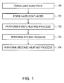
- a coating liquid for forming a dyeable hard coat layer is applied onto a lens substrate, a hard coat layer is heated to be completely cured (in a hardened state with burning), and then the lens substrate having the hard coat layer formed thereon is dyed by a dip dyeing method.
- a coating liquid for forming a dyeable hard coat layer is applied onto a lens substrate, a hard coat layer is heated to be completely cured (in a hardened state with burning), and then the lens substrate having the hard coat layer formed thereon is dyed by a dip dyeing method.
- the annealing process after the dyeing process increases total manufacturing time.
- An advantage of some aspects of the invention is that it provides a method of manufacturing a colored lens, in which a coating liquid for forming a dyeable hard coat layer is applied onto a lens substrate, a hard coat layer is firstly heated to be semi-cured, the lens substrate having the semi-cured hard coat layer is dipped and dyed, and then is secondly heated so as to fix a dye to the hard coat layer, to eliminate distortion occurring at the time of dyeing, and to completely cure the hard coat layer.
- a method of manufacturing a colored lens comprising:
- the management values Q1 and Q2 reflect the amount of heat applied to the lens substrate in the first and second heating steps, respectively. Accordingly, (Q1+Q2) reflects the amount of heat that contributes to curing the hard coat layer. Expression 1 described above reflects that the hard coat layer is not completely cured in the first heating step before the dyeing step.
- the hard coat layer is semi-cured (i.e. the hard coat layer is not completely cured but is dried to such an extent that it can be handled by hand).
- the time required for dyeing is reduced in comparison with a completely-cured hard coat layer of the same material. Accordingly, excellent dyeability can be achieved when dyeing a semi-cured hard coat layer.
- the semi-cured hard coat layer is completely cured by applying the residual heat for curing the hard coat layer. Moreover, in the second heating step, the dye is fixed to the hard coat layer, and in the subsequent steps, the penetrated dye (color) is not removed. Even when the semi-cured hard coat layer is completely cured in the second heating step, it is possible to provide products having no problems in durability such as wear-resistance and close-adhesion.
- the method of manufacturing a colored lens according to the aspect of the invention by applying heat by heat amount Q1 satisfying Expression 1 in the first heating step, it is possible to reduce the total time of the first heating step, and dye the semi-cured hard coat layer.
- dyeing efficiency is improved. Therefore, it is possible to increase dyeing speed, and reduce the total time for performing the dyeing step.
- the residual heat based on the second management value Q2 in the second heating step it is possible to completely cure the semi-cured hard coat layer, as well as to fix the dye to the hard coat layer. Therefore, the time for manufacturing and dyeing the hard coat layer in addition to heating it after dyeing is minimized.
- the dyeing time can be reduced, the total time for performing the steps of manufacturing, dyeing, and annealing the hard coat layer can be reduced.
- a disperse dye is preferably used as the dye used in the dyeing step as this suppresses color unevenness.
- a lens is dipped in an aqueous dyeing solution in a bath.
- the lens lifted from the bath is washed with water, dried, and then dyed by a dip dyeing method using a dye bath.
- the dye used at this time is not particularly limited, but it is preferred to use a dye having high fastness.
- the dye it is possible to use a disperse dye exemplified by an anthraquinone-based dye, a quinophthalone-based dye, a nitrodiphenylamine dye, an azo-based dye or the like.
- disperse dye examples include (i) benzene intermediates such as p-anisidine, aniline, p-aminoacetanilide, p-aminophenol, 1-chloro-2, 4-dinitrobenzene, 2-chloro-4-nitroaniline, o-chloronitrobenzene, diphenylamine, m-nitroaniline, p-nitroaniline, N, N-bis(2-hydroxyethyl)aniline, 1-phenyl-3-methyl-5-pyrazolone, and phenol; (ii) toluene intermediates such as p-cresidine(6-methoxy-m-toluidine), m-cresol, p-cresol, m-toluidine, 2-nitro-p-toluidine, and p-nitrotoluene; (iii) naphthalene intermediates such as 1-naphthylamine and 2-naphthol; (iv) phthalic anhydr
- the disperse dye may be used alone, or in a combination of two or more kinds of disperse dye.
- the disperse dye is provided as a dye bath, wherein the disperse dye is dispersed in water.
- an organic solvent such as methanol, ethanol, or benzyl alcohol may be used with the water.
- a surfactant can be also added to the dye bath as a dispersant for the dye.
- the surfactant include (i) anionic surfactants such as alkylbenzene sulfonates, alkylnaphthalene sulfonates, alkylsulfosuccinates, aromatic sulfonic acid formalin condensates, and lauryl sulfates; and (ii) nonionic surfactants such as polyoxyethylalkyl ethers, alkylamine ethers, and polyoxyethylenesorbitan fatty acid esters.
- surfactants are preferably used in the range of 5 to 200% by weight, based on the amount of dye, the amount of surfactant being selected according to the desired coloring density of the lens.
- a disperse dye and a surfactant are preferably dispersed in water or in a mixture of water and an organic solvent to prepare a dye bath, a plastic lens is dipped in the dye bath, and then the plastic lens is dyed at a predetermined temperature for a predetermined time in hours.
- the dyeing temperature and the dyeing time can be varied according to the desired coloring density.
- the temperature may be 95°C or less and the dyeing time may be in the range of several minutes to about 30 minutes.
- the concentration of the dye in the dye bath is preferably in the range of 0.01 to 5% by weight.
- the temperature T 1 and the temperature T 2 satisfy the following Expressions 2 and 3: 100 ⁇ °C ⁇ T 1 ⁇ 150 ⁇ °C and 100 ⁇ °C ⁇ T 2 ⁇ 150 ⁇ °C
- the temperature T 1 is 100°C or less, the hard coat layer is not cured, uneven coloring occurs and scratches are easily formed at the time of dyeing.
- the temperature T 1 is 150°C or more, the lens substrate is easily yellowed by heat.
- t 1 +t 2 When t 1 +t 2 is shorter than 1 hour, the curing of the hard coat layer is not necessarily satisfactory, and evaluated wear-resistance thereof may be lowered. On the other hand, in the case of a plastic lens, when t 1 +t 2 is longer than 3 hours, the lens substrate may easily be yellowed by heat. In addition, it becomes difficult to effectively reduce the total time for manufacturing a colored lens.
- the hard coat layer may comprise fine metal-oxide particles, a silicon compound, and a polyfunctional epoxy compound.
- the afore-mentioned components are the main components in the dyeable hard coat layer, i.e. these three components together constitute 50 % by weight of the hard coat layer (dry weight).
- the fine metal-oxide particles the following can be used: (i) an antimony oxide coated titanium oxide-containing complex oxide sol dispersed in methanol; or (ii) fine particles or composite fine particles including one or more kinds of metal oxide selected from Si, Al, Sn, Sb, Ta, Ce, La, Fe, Zn, W, Zr, In and Ti.
- the fine metal-oxide particles may be fine particles of which the outermost surfaces are treated with an organosilicon compound for modification, and can be exemplified by fine particles in the form of a mixture, solid solution, or other composite. If titanium oxide is used, this may be either amorphous, or may be an anatase type, rutile type, brookite type, or perovskite type titanium compound.
- fine composite oxide particles may be used after surface treatment with an organosilicon compound or with an amine-based compound.
- organosilicon compound that can be used for this treatment include a monofunctional silane, a difunctional silane, a trifunctional silane, and a tetrafunctional silane.
- the treatment may be carried out without hydrolyzing hydrolyzable groups, or after hydrolyzing the same.
- the state of the fine particles after the treatment is preferably such that the hydrolyzable groups have been reacted with -OH groups on the fine particles. However, even if some unreacted -OH groups remain, the stability is not affected.
- Examples of the amine-based compound include (i) ammonium, (ii) alkylamines such as ethylamine, triethylamine, isopropylamine, and n-propylamine, (iii) aralkylamines such as benzylamine, (iv) alicyclicamines such as piperidine, and (v) alkanolamines such as monoethanolamine and triethanolamine.
- the amount of the organosilicon compound or the amine-based compound to be added is preferably about 1 to 15% of the weight of the fine particles. It is preferable that the particle diameter of any of the above-described fine particles be in the range of approximately 1 to 300 nm.
- a silicon compound is formed using a composition including a component that is an organosilicon compound represented by the following formula (A): R 1 R 2 n six 1 3-n (A) (where n is 0 or 1).
- R 1 is an organic group having a polymerizable reaction group or a hydrolyzable functional group.
- the polymerizable reaction group can include a vinyl group, an allyl group, an acryl group, an methacryl group, an epoxy group, a mercapto group, a cyano group, an amino group and the like.
- the hydrolyzable functional group can include (i) an alkoxy group, preferably a C 1-6 alkoxy group such as a methoxy group, an ethoxy group, or a methoxyethoxy group, (ii) a halogen group such as a chloro group and a bromo group, or (iii) an acyloxy group.
- R 2 is a hydrocarbon group having 1 to 6 carbon atom(s).
- R 2 may be an alkyl group which may be linear, branched or cyclic, or R 2 may be aromatic. Specific examples of the R 2 hydrocarbon group include a methyl group, an ethyl group, a butyl group, a vinyl group and a phenyl group.
- X 1 is a hydrolyzable functional group.
- hydrolyzable functional group examples include (i) an alkoxy group, preferably a C 1-6 alkoxy group such as a methoxy group, an ethoxy group, or a methoxyethoxy group, (ii) a halogen group such as a chloro group and a bromo group, or (iii) an acyloxy group.
- organosilicon compound represented by the above formula (A) examples include vinyltrialkoxysilanes, vinyltrichlorosilane, vinyltri( ⁇ -methoxy-ethoxy)silane, allyltrialkoxysilanes, acryloxypropyltrialkoxysilanes, methacryloxypropyltrialkoxysilanes, methacryloxypropyldialkoxymethylsilanes, ⁇ -glycidoxypropyl-trialkoxysilanes, ⁇ -(3,4-epoxycyclohexyl)-ethyltrialkoxy-silanes, mercaptopropyltrialkoxysilanes, ⁇ -aminopropyltrialkoxysilanes, N- ⁇ (aminoethyl)- ⁇ -aminopropylmethyldialkoxysilanes, tetramethoxysilanes, and ⁇ -glycidoxypropyl-trime
- polyfunctional epoxy compound examples include (i) polyolefin epoxy resins synthesized by aperoxidation process, (ii) alicyclic epoxy resins such as polyglycidyl ester obtainable from cyclopentadiene oxide, cyclohexene oxide or hexahydrophthalic acid and epichlorohydrin, (iii) polyglycidyl ethers obtainable from polyhydric phenols such as bisphenol A, catechol and resorcinol, or polyhydric alcohols such as (poly)ethylene glycol, (poly)propylene glycol, neopentyl glycol, glycerin, trimethylol propane, pentaerythritol, diglycerol and sorbitol, and epichlorohydrin, (iv) epoxidized vegetable oils, (v) epoxynovolaks obtainable from novolak-type phenol resins and epichlorohydrin, (vi) epoxy resins obtainable from
- preferable polyfunctional epoxy compounds include (i) aliphatic epoxy compounds such as 1,6-hexanediol diglycidyl ether, ethylene glycol diglycidyl ether, diethylene glycol diglycidyl ether, triethylene glycol diglycidyl ether, tetraethylene glycol diglycidyl ether, nonaethylene glycol diglycidyl ether, propylene glycol diglycidyl ether, dipropylene glycol diglycidyl ether, tripropylene glycol diglycidyl ether, tetrapropylene glycol diglycidyl ether, nonapropylene glycoldiglycidyl ether, neopentyl glycol diglycidyl ether, diglycidyl ether of neopentyl glycol hydroxypivalic ester, trimethylolpropane diglycidyl ether, trimethylolpropane triglycidyl ether, glyce
- the components included in the hard coat layer are not limited to the above. If necessary, any additive can be used in addition to the above-mentioned components when the hard coat layer is formed.
- An example of such an additive is a curing catalyst.
- the curing catalyst include (i) perchloric acids such as perchloric acid, ammonium perchlorate, and magnesium perchlorate, (ii) acetylacetonate having e.g.
- examples of the most preferable curing catalyst include magnesium perchlorate, and acetylacetonate of Al (III) or Fe (III).
- the amount of the additive to be added is preferably in the range of 0.01 to 5.0% by weight in the solid content concentration.
- a solvent may be used in addition to the above-mentioned components in the manufacturing process.
- the solvent that can be used for dilution include (i) alcohols, (ii) esters, (iii) ketones, (iv) ethers, and (v) aromatic solvents.
- a surfactant, an antistatic agent, a disperse dye, an oil soluble dye, a fluorescent dye, a pigment or a photochromic compound may be added as needed to enable improvement in coating properties of the coating liquid for forming the hard coat layer, and coated film performances following curing.
- additional layers may be formed on the hard layer after the second heating step. For example, an anti-reflection layer and/or an anti-fouling layer may be formed.
- Fig. 1 is a flow chart showing a method of manufacturing a colored lens according to the present invention.
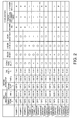
- Fig. 2 is a table showing manufacturing conditions of lenses in examples and comparative examples, dyeability, and test results for dyeing workability, yellow degree, uneven coloring, wear-resistance and close-adhesion.
- Fig. 3 is a table showing evaluations for the lenses in the examples and the comparative examples.
- Fig. 1 shows an outline of the lens manufacturing steps according to an embodiment of the invention; this procedure was followed in the examples and comparative examples.
- a plastic lens substrate having a refractive index of 1.67 was formed using a lens for "Seiko Super Sovereign", manufactured by Seiko Epson Corporation (hereinafter, abbreviated as SSV).
- a coating liquid for forming a dyeable hard coat layer was applied onto the lens substrate by a dipping method (coating step).
- the coating liquid was prepared as follows. A mixture of 103.2 g of butylcellosolve and 35.3 g of ⁇ -glycidoxypropyl-trimethoxysilane was prepared. 9.7 g of 0.1N HCl solution was added to the mixture and stirred. After the stirring was performed for 3 hours, the mixture was aged for a whole day and night. To this liquid, 312.5 g of a titanium oxide-containing complex oxide sol dispersed in methanol (manufactured by CATALYSTS & CHEMICALS IND.
- Step 102 the lens substrate coated with the coating liquid was heated at the temperature T 1 °C for t 1 hours (first heating step).
- Step 103 a bath at 90°C in which a dye was dispersed and an activator was mixed was prepared, and the lens substrate heated at the temperature T 1 °C for t 1 hours was dipped in this bath for t 3 hours such that the luminous transmittance was controlled to 50%.
- the hard coat layer thereon was dyed (dyeing step).
- the dye to be dispersed Amber D for Seiko Plux Diamond Coat was used.
- Step 104 the lens substrate having the dyed hard coat layer was heated at the temperature T 2 °C for t 2 hours (second heating step). Accordingly, the dyed hard coat layer having a thickness of 1.0 ⁇ m was formed on the lens substrate.
- the solid content ratio of the burned hard coat layer obtained by the coating liquid (after the second heating step), that is, metal oxide : silane compound : polyfunctional epoxy compound was about 50 : 20 : 30.
- samples were prepared by changing the temperature T 1 (°C), time t 1 (hour), temperature T 2 (°C), time t 2 (hour) .
- the first management value Q1 (°C ⁇ H) is the product of the temperature T 1 and the time t 1
- the second management value Q2 is the product of the temperature T 2 and the time t 2
- (Q1+Q2) is the sum of the Q1 and Q2.
- the samples in which the ratio Q1/(Q1+Q2) satisfies the above-mentioned Expression 1 are exemplary samples, and the samples in which the ratio Q1/(Q1+Q2) does not satisfy the above-mentioned Expression 1 are comparative samples.
- Fig. 2 shows manufacturing conditions of the exemplary lens samples and the comparative lens samples, dyeability, and test results for dyeing workability, yellow degree, uneven coloring, wear-resistance and close-adhesion.
- Fig. 3 shows evaluations for the exemplary lens samples and the comparative lens samples.
- the first heating step was performed at 125°C (temperature T 1 ) for 0.50 hours (time t 1 ) .
- Three minutes was required to control the luminous transmittance to 50% in the dyeing step.
- the second heating step was performed at 125°C (temperature T 2 ) for 1.50 hours (time t 2 ) .
- (Q1+Q2) corresponding to the total amount of heat is 250.0 (rounded to one decimal place).
- the ratio Q1/(Q1+Q2) corresponding to heat distribution is 0.3 (rounded to one decimal place), and satisfies Expression 1.
- Total time (total lead time) P t (t 1 +t 2 +t 3 ) required for the heating and dyeing was 123 minutes.
- the first heating step was performed at 125°C (temperature T 1 ) for 0.50 hours (time t 1 ). Three minutes was required to control the luminous transmittance to 50% in the dyeing step.
- the second heating step was performed at 125°C (temperature T 2 ) for 0.50 hours (time t 2 ) .
- Example 2 the management value Q1 corresponding to the amount of heat for the first heating step is 62.5 (rounded to one decimal place), the management value Q2 corresponding to the amount of heat for the second heating step is 62.5 (rounded to one decimal place), and (Q1+Q2) corresponding to the total amount of heat is 125.0 (rounded to one decimal place).
- the ratio Q1/(Q1+Q2) corresponding to heat distribution is 0.5 (rounded to one decimal place), and satisfies Expression 1.
- Total lead time (t 1 +t 2 +t 3 ) was 63 minutes.
- the first heating step was performed at 125°C (temperature T 1 ) for 1.00 hour (time t 1 ).
- Six minutes was required to control the luminous transmittance to 50% in the dyeing step.
- the second heating step was performed at 125°C (temperature T 2 ) for 1.00 hour (time t 2 ) .
- Example 3 the management value Q1 corresponding to the amount of heat for the first heating step is 125.0 (rounded to one decimal place), the management value Q2 corresponding to the amount of heat for the second heating step is 125.0 (rounded to one decimal place), and (Q1+Q2) corresponding to the total amount of heat is 250.0 (rounded to one decimal place).
- the ratio Q1/(Q1+Q2) corresponding to heat distribution is 0.5 (rounded to one decimal place), and satisfies Expression 1.
- Total lead time (t 1 +t 2 +t 3 ) was 126 minutes.
- the first heating step was performed at 125°C (temperature T 1 ) for 1.00 hour (time t 1 ). Six minutes was required to control the luminous transmittance to 50% in the dyeing step.
- the second heating step was performed at 80°C (temperature T 2 ) for 0.50 hours (time t 2 ) .
- the management value Q1 corresponding to the amount of heat for the first heating step is 125.0 (rounded to one decimal place)
- the management value Q2 corresponding to the amount of heat for the second heating step is 40.0 (rounded to one decimal place)
- (Q1+Q2) corresponding to the total amount of heat is 165.0 (rounded to one decimal place).
- the ratio Q1/(Q1+Q2) corresponding to heat distribution is 0.8 (rounded to one decimal place), and does not satisfy Expression 1.
- Total lead time (t 1 +t 2 +t 3 ) was 96 minutes.
- the first heating step was performed at 80°C (temperature T 1 ) for 0.50 hours (time t 1 ).
- One minute was required to control the luminous transmittance to 50% in the dyeing step.
- the second heating step was performed at 125°C (temperature T 2 ) for 1.50 hours (time t 2 ) .
- the management value Q1 corresponding to the amount of heat for the first heating step is 40.0 (rounded to one decimal place)
- the management value Q2 corresponding to the amount of heat for the second heating step is 187.5 (rounded to one decimal place)
- (Q1+Q2) corresponding to the total amount of heat is 227.5 (rounded to one decimal place).
- the ratio Q1/(Q1+Q2) corresponding to heat distribution is 0.2 (rounded to one decimal place), and does not satisfy Expression 1.
- Total lead time (t 1 +t 2 +t 3 ) was 121 minutes.
- the first heating step was performed at 125°C (temperature T 1 ) for 0.25 hours (time t 1 ).
- time t 1 One minute was required to control the luminous transmittance to 50% in the dyeing step.
- the second heating step was performed at 125°C (temperature T 2 ) for 1.75 hours (time t 2 ) .
- the management value Q1 corresponding to the amount of heat for the first heating step is 31.3 (rounded to one decimal place)
- the management value Q2 corresponding to the amount of heat for the second heating step is 218.8 (rounded to one decimal place)
- (Q1+Q2) corresponding to the total amount of heat is 250.0 (rounded to one decimal place).
- the ratio Q1/(Q1+Q2) corresponding to heat distribution is 0.1 (rounded to one decimal place), and does not satisfy Expression 1.
- Total lead time (t 1 +t 2 +t 3 ) was 121 minutes.
- the first heating step was performed at 125°C (temperature T 1 ) for 2.00 hours (time t 1 ) .
- Ten minutes was required to control the luminous transmittance to 50% in the dyeing step.
- the second heating step was performed at 125°C (temperature T 2 ) for 1.00 hours (time t 2 ) .
- the management value Q1 corresponding to the amount of heat for the first heating step is 250.0 (rounded to one decimal place)
- the management value Q2 corresponding to the amount of heat for the second heating step is 125.0 (rounded to one decimal place)
- (Q1+Q2) corresponding to the total amount of heat is 375.0 (rounded to one decimal place).
- the ratio Q1/(Q1+Q2) corresponding to heat distribution is 0.7 (rounded to one decimal place), and does not satisfy Expression 1.
- Total lead time (t 1 +t 2 +t 3 ) was 190 minutes.
- the first heating step was performed at 125°C (temperature T 1 ) for 3.00 hours (time t 1 ). Twelve minutes was required to control the luminous transmittance to 50% in the dyeing step.
- the second heating step was performed at 125°C (temperature T 2 ) for 1.00 hour (time t 2 ) .
- the management value Q1 corresponding to the amount of heat for the first heating step is 375.0 (rounded to one decimal place)
- the management value Q2 corresponding to the amount of heat for the second heating step is 125.0 (rounded to one decimal place)
- (Q1+Q2) corresponding to the total amount of heat is 500.0 (rounded to one decimal place).
- the ratio Q1/(Q1+Q2) corresponding to heat distribution is 0.8 (rounded to one decimal place), and does not satisfy Expression 1.
- Total lead time (t 1 +t 2 +t 3 ) was 252 minutes.
- the first heating step was performed at 125°C (temperature T 1 ) for 6.00 hours (time t 1 ) . Fifteen minutes was required to control the luminous transmittance to 50% in the dyeing step.
- the second heating step was performed at 125°C (temperature T 2 ) for 1.00 hour (time t 2 ) .
- the management value Q1 corresponding to the amount of heat for the first heating step is 750.0 (rounded to one decimal place)
- the management value Q2 corresponding to the amount of heat for the second heating step is 125.0 (rounded to one decimal place)
- (Q1+Q2) corresponding to the total amount of heat is 875.0 (rounded to one decimal place).
- the ratio Q1/(Q1+Q2) corresponding to heat distribution is 0.9 (rounded to one decimal place), and does not satisfy Expression 1.
- Total lead time (t 1 +t 2 +t 3 ) was 435 minutes.
- the first heating step was performed at 150°C (temperature T 1 ) for 0.25 hours (time t 1 ) .
- Three minutes was required to control the luminous transmittance to 50% in the dyeing step.
- the second heating step was performed at 125°C (temperature T 2 ) for 2.00 hours (time t 2 ) .
- the management value Q1 corresponding to the amount of heat for the first heating step is 37.5 (rounded to one decimal place)
- the management value Q2 corresponding to the amount of heat for the second heating step is 250.0 (rounded to one decimal place)
- (Q1+Q2) corresponding to the total amount of heat is 287.5 (rounded to one decimal place).
- the ratio Q1/(Q1+Q2) corresponding to heat distribution is 0.1 (rounded to one decimal place), and does not satisfy Expression 1.
- Total lead time (t 1 +t 2 +t 3 ) was 138 minutes.
- the first heating step was performed at 125°C (temperature T 1 ) for 2.00 hours (time t 1 ) .
- Ten minutes was required to control the luminous transmittance to 50% in the dyeing step.
- the second heating step was performed at 120°C (temperature T 2 ) for 1.00 hour (time t 2 ) .
- the management value Q1 corresponding to the amount of heat for the first heating step is 250.0 (rounded to one decimal place)
- the management value Q2 corresponding to the amount of heat for the second heating step is 120.0 (rounded to one decimal place)
- (Q1+Q2) corresponding to the total amount of heat is 370.0 (rounded to one decimal place).
- the ratio Q1/(Q1+Q2) corresponding to heat distribution is 0.7 (rounded to one decimal place), and does not satisfy Expression 1.
- Total lead time (t 1 +t 2 +t 3 ) was 190 minutes.
- the first heating step was performed at 125°C (temperature T 1 ) for 0.25 hours (time t 1 ).
- One minute was required to control the luminous transmittance to 50% in the dyeing step.
- the second heating step was performed at 150°C (temperature T 2 ) for 2.00 hours (time t 2 ) .
- the management value Q1 corresponding to the amount of heat for the first heating step is 31.3 (rounded to one decimal place)
- the management value Q2 corresponding to the amount of heat for the second heating step is 300.0 (rounded to one decimal place)
- (Q1+Q2) corresponding to the total amount of heat is 331.3 (rounded to one decimal place).
- the ratio Q1/(Q1+Q2) corresponding to heat distribution is 0.1 (rounded to one decimal place), and does not satisfy Expression 1.
- Total lead time (t 1 +t 2 +t 3 ) was 138 minutes.
- the first heating step was performed at 125°C (temperature T 1 ) for 0.25 hours (time t 1 ).
- time t 1 The procedure described above and which is outlined in Fig. 1 was followed.
- the first heating step was performed at 125°C (temperature T 1 ) for 0.25 hours (time t 1 ).
- Six minute was required to control the luminous transmittance to 50% in the dyeing step.
- the second heating step was performed at 80°C (temperature T 2 ) for 0.25 hours (time t 2 ).
- the management value Q1 corresponding to the amount of heat for the first heating step is 31.3 (rounded to one decimal place)
- the management value Q2 corresponding to the amount of heat for the second heating step is 20.0 (rounded to one decimal place)
- (Q1+Q2) corresponding to the total amount of heat is 51.3 (rounded to one decimal place).
- the ratio Q1/(Q1+Q2) corresponding to heat distribution is 0.6 (rounded to one decimal place), and does not satisfy Expression 1.
- Total lead time (t 1 +t 2 +t 3 ) was 36 minutes.
- the yellow degree was checked by the naked eye.
- O means that the discoloration to yellow does not occur
- ⁇ means that a very small discoloration to yellow occurs
- X means that the discoloration to yellow is confirmed by the naked eye.
- the evaluation criteria for the wear-resistance include 10 scratch levels (1 (bad) to 10 (good)) that are decided by checking the degree of scratching with the naked eye.
- ⁇ means that the level is in the range of 10 to 8 and the wear-resistance is very high
- O means that the level is in the range of 7 to 6 and the wear-resistance is high
- ⁇ means that the level is in the range of 5 to 4 and the wear-resistance is slightly low
- X means that the level is in the range of 3 to 1 and the wear-resistance is low.
- the close-adhesion was tested by leaving the lens samples in three different conditions.
- the lens samples were exposed to arc light in which carbon atoms are electrically discharged for 120 hours (corresponding to the exposure for 120 hours under the sun).
- a cross-cut tape test was performed according to JISD-0202.
- JISD-0202. To determine the close-adhesion of the lens samples left in the constant-temperature and humidity, the lens samples were left for 7 days under the conditions of a temperature of 60°C and an RH of 99%.
- the cross-cut tape test was performed to the lens samples according to JISD-0202.
- the lens samples were left in the hot water at 90°C for 1.5 hours.
- the cross-cut tape test was performed to the lens samples according to JISD-0202.
- the ratio Q1/(Q1+Q2), the temperature T 1 , the temperature T 2 , and the total time P t satisfy the above-mentioned Expressions 1 to 4.
- All of the colored lenses manufactured in accordance with Examples 1 to 3 are excellent in the dyeing workability, uneven coloring, wear-resistance and close-adhesion. Also, the above colored lenses are not yellowed.
- the colored lenses manufactured in accordance with Examples 1 to 3 are excellent in the dyeing workability, uneven coloring, wear-resistance and close-adhesion, and are not yellowed.
- the dyeability (dyeing time) t 3 of the colored lenses is checked, it can be known that the dyeing time is short and the dyeing speed is fast in comparison with Comparative Examples 4 to 8. Further, the total time P t is shorter than those of the colored lenses manufactured in accordance with Comparative Examples 4 to 8. That is, a colored lens having excellent properties can be manufactured for a short period of time.
- the ratio Q1/(Q1+Q2) is 0.8, and does not satisfy the above-mentioned Expression 1.
- the temperature T 2 for the second heating step is 80°C, and does not satisfy the above-mentioned Expression 3.
- the amount of heat for the second heating step is too small because the ratio Q1/(Q1+Q2) is larger than 0.5 and the temperature T 2 for the second heating step is too low. Since the colored lens manufactured in accordance with Comparative Example 1 has unrecovered unevenness on the lens surface thereof, the wear-resistance and close-adhesion can not be accurately evaluated.
- the ratio Q1/(Q1+Q2) corresponding to the heat distribution is 0.2, and does not satisfy the above-mentioned Expression 1.
- the temperature T 1 for the first heating step is 80°C, and does not satisfy the above-mentioned Expression 2.
- the hard coat layer is peeled off when the test for dyeing workability is performed. The reason for this is that the amount of heat for the first heating step is too small because the ratio Q1/(Q1+Q2) is 0.2 or less and the temperature T 1 for the first heating step is too low. Since the hard coat layer is peeled off from the colored lens manufactured in accordance with Comparative Example 2 at the time of performing the test for dyeing workability, the wear-resistance and close-adhesion can not be accurately evaluated.
- the ratio Q1/(Q1+Q2) corresponding to the heat distribution is 0.1, and does not satisfy the above-mentioned Expression 1.
- the hard coat layer is peeled off when the test for dyeing workability is performed. The reason for this is that the ratio Q1/(Q1+Q2) is 0.2 and the amount of heat for the first heating step is small. Since the hard coat layer is peeled off from the colored lens manufactured in accordance with Comparative Example 3 at the time of performing the test for the dyeing workability, the wear-resistance and close-adhesion can not be accurately evaluated.
- Comparative Example 4 the ratio Q1/(Q1+Q2) corresponding to the heat distribution is 0.7, and does not satisfy the above-mentioned Expression 1.
- the colored lens manufactured in accordance with Comparative Example 4 is excellent in the dyeing workability, uneven coloring, wear-resistance, and close-adhesion, and is not yellowed.
- the total time is long in comparison with Examples 1 to 3. That is, it takes a long time for manufacturing.
- the ratio Q1/(Q1+Q2) corresponding to the heat distribution is 0.8, and does not satisfy the above-mentioned Expression 1. Further, the total heating time (t 1 +t 2 ) of the first heating time t 1 and the second heating time t 2 is 4 hours, and does not satisfy the above-mentioned Expression 4.
- the colored lens manufactured in accordance with Comparative Example 5 is slightly yellowed. The reason for this is that the ratio Q1/(Q1+Q2) corresponding to the heat distribution is larger than 0.5 and the total heating time (t 1 +t 2 ) is long.
- the ratio Q1/(Q1+Q2) corresponding to the heat distribution is 0.9, and does not satisfy the above-mentioned Expression 1. Further, the total heating time (t 1 +t 2 ) of the first heating time t 1 and the second heating time t 2 is 7 hours, and does not satisfy the above-mentioned Expression 4.
- the discoloration to yellow is confirmed by the naked eye. The reason for this is that the ratio Q1/(Q1+Q2) corresponding to the heat distribution is larger than 0.5 and the total heating time (t 1 +t 2 ) is too long.
- the discoloration to yellow is confirmed by the naked eye in the colored lens manufactured in accordance with Comparative Example 6, the wear-resistance and close-adhesion can not be accurately evaluated.
- the ratio Q1/(Q1+Q2) corresponding to the heat distribution is 0.1, and does not satisfy the above-mentioned Expression 1.
- the temperature T 1 for the first heating step is 150°C, and does not satisfy the above-mentioned Expression 2.
- the discoloration to yellow is confirmed by the naked eye. The reason for this is that the temperature T 1 for the first heating step is too high.
- the wear-resistance and close-adhesion can not be accurately evaluated.
- Comparative Example 8 the ratio Q1/(Q1+Q2) corresponding to the heat distribution is 0.7, and does not satisfy the above-mentioned Expression 1.
- the colored lens manufactured in accordance with Comparative Example 8 is excellent in the dyeing workability, uneven coloring, wear-resistance, and close-adhesion, and is not yellowed.
- the total time is long in comparison with Examples 1 to 3. That is, it takes a long time for manufacturing.
- the ratio Q1/(Q1+Q2) corresponding to the heat distribution is 0.1, and does not satisfy the above-mentioned Expression 1.
- the temperature T 2 for the second heating step is 150°C, and does not satisfy the above-mentioned Expression 3.
- the discoloration to yellow is confirmed by the naked eye. The reason for this is that the amount of heat for the second heating step is too large because the ratio Q1/(Q1+Q2) is below 0.2 and the temperature T 2 for the second heating step is too high. Since the discoloration to yellow is confirmed by the naked eye in the colored lens manufactured in accordance with Comparative Example 9, the wear-resistance and close-adhesion can not be accurately evaluated.
- the ratio Q1/(Q1+Q2) corresponding to the heat distribution is 0.6, and does not satisfy the above-mentioned Expression 1. Further, the temperature T 2 for the second heating step is 80°C, and does not satisfy the above-mentioned Expression 3.
- the hard coat layer is peeled off when the test for dyeing workability is performed, and distortion remains on the lens surface subjected to the second heating step. The reason for this is that the amount of heat Q2 for the second heating step is too small because the ratio Q1/(Q1+Q2) is larger than 0.5 and the temperature T 2 for the second heating step is too low.
- a plastic lens is exemplified as a substrate in the examples.
- a glass lens may be used as the substrate.
- a plastic lens used for glasses is manufactured as a colored lens, and durability such as close-adhesion and wear-resistance is evaluated in addition to dyeability.
- a dyed lens (optical element) applicable to the invention is not limited to a spectacle lens but may be a lens for camera. The invention is applicable to other optical elements, for example, a prism.
Abstract
Description
- The present invention relates to a method of manufacturing a colored lens of plastic or glass, which glass can be used, inter alia, in the manufacture of glasses.
- Instead of dyeing a plastic lens or a glass lens constituting a substrate, it is known to dye a functional layer of a colored lens, for example, a hard coat layer which is stacked on a substrate. Colored lenses are generally used as a lens for vision correction or a spectacle lens such as sunglasses.
JP-A-11-310755 - Reduction in dyeing time and total manufacturing time has been required in a method of manufacturing a colored lens.
- In known methods of manufacturing a colored lens, a coating liquid for forming a dyeable hard coat layer is applied onto a lens substrate, a hard coat layer is heated to be completely cured (in a hardened state with burning), and then the lens substrate having the hard coat layer formed thereon is dyed by a dip dyeing method. As a result of extensive and intensive studies for dyed lenses, it has been known that it is desirable to perform an annealing process for about one hour after a dyeing process in order to prevent uneven coloring from occurring and fix a color and then it is desirable to form an anti-reflection layer if necessary. However, the annealing process after the dyeing process increases total manufacturing time.
- An advantage of some aspects of the invention is that it provides a method of manufacturing a colored lens, in which a coating liquid for forming a dyeable hard coat layer is applied onto a lens substrate, a hard coat layer is firstly heated to be semi-cured, the lens substrate having the semi-cured hard coat layer is dipped and dyed, and then is secondly heated so as to fix a dye to the hard coat layer, to eliminate distortion occurring at the time of dyeing, and to completely cure the hard coat layer.
- In an aspect of the invention, there is provided a method of manufacturing a colored lens, the method comprising:
- (i) applying a coating liquid for forming a dyeable hard coat layer onto a lens substrate, or indirectly onto the lens substrate by interposing another layer therebetween;
- (ii) heating the lens substrate coated with the coating liquid in a first heating step at a temperature of T1°C for t1 hours to form a semi-cured hard coat layer formed on the lens substrate;
- (iii) dyeing the semi-cured hard coat layer formed on the lens substrate by dipping it in a dyeing liquid; and
- (iv) heating the lens substrate on which the dyed, semi-cured hard coat layer is formed in a second heating step at a temperature of T2°C for t2 hours to form a completely cured hard coat layer. Here, when the product of the temperature T1 (°C) and the time t1 (hours) is a first management value Q1, the product of the temperature T2 (°C) and the time t2 (hours) is a second management value Q2, the relationship between the first management value Q1 and (Q1 + Q2) satisfies the following Expression 1:

- The management values Q1 and Q2 reflect the amount of heat applied to the lens substrate in the first and second heating steps, respectively. Accordingly, (Q1+Q2) reflects the amount of heat that contributes to curing the hard coat layer.
Expression 1 described above reflects that the hard coat layer is not completely cured in the first heating step before the dyeing step. - By adjusting the first management value Q1 in the first heating step to 50% or less of (Q1+Q2) corresponding to the total amount of heat, the hard coat layer is semi-cured (i.e. the hard coat layer is not completely cured but is dried to such an extent that it can be handled by hand). When a semi-cured hard coat layer is dyed, the time required for dyeing is reduced in comparison with a completely-cured hard coat layer of the same material. Accordingly, excellent dyeability can be achieved when dyeing a semi-cured hard coat layer.
- In the second heating step, the semi-cured hard coat layer is completely cured by applying the residual heat for curing the hard coat layer. Moreover, in the second heating step, the dye is fixed to the hard coat layer, and in the subsequent steps, the penetrated dye (color) is not removed. Even when the semi-cured hard coat layer is completely cured in the second heating step, it is possible to provide products having no problems in durability such as wear-resistance and close-adhesion.
- As shown in
Expression 1, when the ratio Q1/(Q1+Q2) is 0.2 or less because the first management value Q1 is too small, scratches are formed at the time of dyeing. On the other hand, when the ratio Q1/(Q1+Q2) is larger than 0.5 because the first management value Q1 is large, there is no great influence on reduction in dyeing time. - Accordingly, in the method of manufacturing a colored lens according to the aspect of the invention, by applying heat by heat amount
Q1 satisfying Expression 1 in the first heating step, it is possible to reduce the total time of the first heating step, and dye the semi-cured hard coat layer. Thus, dyeing efficiency is improved. Therefore, it is possible to increase dyeing speed, and reduce the total time for performing the dyeing step. Then, by applying the residual heat based on the second management value Q2 in the second heating step, it is possible to completely cure the semi-cured hard coat layer, as well as to fix the dye to the hard coat layer. Therefore, the time for manufacturing and dyeing the hard coat layer in addition to heating it after dyeing is minimized. In addition, since the dyeing time can be reduced, the total time for performing the steps of manufacturing, dyeing, and annealing the hard coat layer can be reduced. - In the method of manufacturing a colored lens according to the present invention, a disperse dye is preferably used as the dye used in the dyeing step as this suppresses color unevenness. In the dyeing step, a lens is dipped in an aqueous dyeing solution in a bath. Next, the lens lifted from the bath is washed with water, dried, and then dyed by a dip dyeing method using a dye bath. The dye used at this time is not particularly limited, but it is preferred to use a dye having high fastness.
- As the dye, it is possible to use a disperse dye exemplified by an anthraquinone-based dye, a quinophthalone-based dye, a nitrodiphenylamine dye, an azo-based dye or the like. Specific examples of the disperse dye include (i) benzene intermediates such as p-anisidine, aniline, p-aminoacetanilide, p-aminophenol, 1-chloro-2, 4-dinitrobenzene, 2-chloro-4-nitroaniline, o-chloronitrobenzene, diphenylamine, m-nitroaniline, p-nitroaniline, N, N-bis(2-hydroxyethyl)aniline, 1-phenyl-3-methyl-5-pyrazolone, and phenol; (ii) toluene intermediates such as p-cresidine(6-methoxy-m-toluidine), m-cresol, p-cresol, m-toluidine, 2-nitro-p-toluidine, and p-nitrotoluene; (iii) naphthalene intermediates such as 1-naphthylamine and 2-naphthol; (iv) phthalic anhydride; and (v) anthraquinone intermediates such as 1-amino-4-bromoanthraquinone-2-sulfonic acid (bromamine acid), 1-anthraquinonesulfonic acid, 1,4-diaminoanthraquinone, 1,5-dichloroanthraquinone, 1,4-dihydroxyanthraquinone (quinizarin), 1,5-dihydroxyanthraquinone (anthrarufin), 1,2,4-trihydroxyanthraquinone (purpurin), and 2-methylanthraquinone. The disperse dye may be used alone, or in a combination of two or more kinds of disperse dye. Generally, the disperse dye is provided as a dye bath, wherein the disperse dye is dispersed in water. As a solvent, an organic solvent such as methanol, ethanol, or benzyl alcohol may be used with the water.
- Further, a surfactant can be also added to the dye bath as a dispersant for the dye. Examples of the surfactant include (i) anionic surfactants such as alkylbenzene sulfonates, alkylnaphthalene sulfonates, alkylsulfosuccinates, aromatic sulfonic acid formalin condensates, and lauryl sulfates; and (ii) nonionic surfactants such as polyoxyethylalkyl ethers, alkylamine ethers, and polyoxyethylenesorbitan fatty acid esters. These surfactants are preferably used in the range of 5 to 200% by weight, based on the amount of dye, the amount of surfactant being selected according to the desired coloring density of the lens. In the dipping and dyeing treatment, a disperse dye and a surfactant are preferably dispersed in water or in a mixture of water and an organic solvent to prepare a dye bath, a plastic lens is dipped in the dye bath, and then the plastic lens is dyed at a predetermined temperature for a predetermined time in hours. The dyeing temperature and the dyeing time can be varied according to the desired coloring density. The temperature may be 95°C or less and the dyeing time may be in the range of several minutes to about 30 minutes. The concentration of the dye in the dye bath is preferably in the range of 0.01 to 5% by weight.
- In the method of manufacturing a colored lens according to the present invention, it is desirable that the temperature T1 and the temperature T2 satisfy the following
Expressions 2 and 3:

- When the temperature T1 is 100°C or less, the hard coat layer is not cured, uneven coloring occurs and scratches are easily formed at the time of dyeing. On the other hand, in the case of a plastic lens, when the temperature T1 is 150°C or more, the lens substrate is easily yellowed by heat.
- Similarly, when the temperature T2 is 100°C or less, uneven coloring occurs and scratches are easily formed at the time of dyeing. On the other hand, when the temperature T2 is 150°C or more, the lens substrate is easily yellowed by heat.
- In addition, in the method of manufacturing a colored lens according to the present invention, it is desirable that the sum of the time t1 and the time t2 satisfies the following Expression 4:

- When t1+t2 is shorter than 1 hour, the curing of the hard coat layer is not necessarily satisfactory, and evaluated wear-resistance thereof may be lowered. On the other hand, in the case of a plastic lens, when t1+t2 is longer than 3 hours, the lens substrate may easily be yellowed by heat. In addition, it becomes difficult to effectively reduce the total time for manufacturing a colored lens.
- In the method of manufacturing a colored lens according to the present invention, the hard coat layer may comprise fine metal-oxide particles, a silicon compound, and a polyfunctional epoxy compound. Preferably, the afore-mentioned components are the main components in the dyeable hard coat layer, i.e. these three components together constitute 50 % by weight of the hard coat layer (dry weight).
- As the fine metal-oxide particles, the following can be used: (i) an antimony oxide coated titanium oxide-containing complex oxide sol dispersed in methanol; or (ii) fine particles or composite fine particles including one or more kinds of metal oxide selected from Si, Al, Sn, Sb, Ta, Ce, La, Fe, Zn, W, Zr, In and Ti. The fine metal-oxide particles may be fine particles of which the outermost surfaces are treated with an organosilicon compound for modification, and can be exemplified by fine particles in the form of a mixture, solid solution, or other composite. If titanium oxide is used, this may be either amorphous, or may be an anatase type, rutile type, brookite type, or perovskite type titanium compound. These may be colloidally dispersed in a dispersion medium, for example, in water, in an alcohol, or in another organic solvent. In addition, fine composite oxide particles may be used after surface treatment with an organosilicon compound or with an amine-based compound. Examples of the organosilicon compound that can be used for this treatment include a monofunctional silane, a difunctional silane, a trifunctional silane, and a tetrafunctional silane. The treatment may be carried out without hydrolyzing hydrolyzable groups, or after hydrolyzing the same. Further, the state of the fine particles after the treatment is preferably such that the hydrolyzable groups have been reacted with -OH groups on the fine particles. However, even if some unreacted -OH groups remain, the stability is not affected. Examples of the amine-based compound include (i) ammonium, (ii) alkylamines such as ethylamine, triethylamine, isopropylamine, and n-propylamine, (iii) aralkylamines such as benzylamine, (iv) alicyclicamines such as piperidine, and (v) alkanolamines such as monoethanolamine and triethanolamine. The amount of the organosilicon compound or the amine-based compound to be added is preferably about 1 to 15% of the weight of the fine particles. It is preferable that the particle diameter of any of the above-described fine particles be in the range of approximately 1 to 300 nm.
- It is preferable that a silicon compound is formed using a composition including a component that is an organosilicon compound represented by the following formula (A):
R1R2 nsix1 3-n (A)
(where n is 0 or 1). - In the formula (A), R1 is an organic group having a polymerizable reaction group or a hydrolyzable functional group. Specific examples of the polymerizable reaction group can include a vinyl group, an allyl group, an acryl group, an methacryl group, an epoxy group, a mercapto group, a cyano group, an amino group and the like. Specific examples of the hydrolyzable functional group can include (i) an alkoxy group, preferably a C1-6 alkoxy group such as a methoxy group, an ethoxy group, or a methoxyethoxy group, (ii) a halogen group such as a chloro group and a bromo group, or (iii) an acyloxy group.
- In the formula (A), R2 is a hydrocarbon group having 1 to 6 carbon atom(s). R2 may be an alkyl group which may be linear, branched or cyclic, or R2 may be aromatic. Specific examples of the R2 hydrocarbon group include a methyl group, an ethyl group, a butyl group, a vinyl group and a phenyl group. In addition, in the formula (A), X1 is a hydrolyzable functional group. Specific examples of the hydrolyzable functional group include (i) an alkoxy group, preferably a C1-6 alkoxy group such as a methoxy group, an ethoxy group, or a methoxyethoxy group, (ii) a halogen group such as a chloro group and a bromo group, or (iii) an acyloxy group.
- Specific examples of the organosilicon compound represented by the above formula (A) include vinyltrialkoxysilanes, vinyltrichlorosilane, vinyltri(β-methoxy-ethoxy)silane, allyltrialkoxysilanes, acryloxypropyltrialkoxysilanes, methacryloxypropyltrialkoxysilanes, methacryloxypropyldialkoxymethylsilanes, γ-glycidoxypropyl-trialkoxysilanes, β-(3,4-epoxycyclohexyl)-ethyltrialkoxy-silanes, mercaptopropyltrialkoxysilanes, γ-aminopropyltrialkoxysilanes, N-β(aminoethyl)-γ-aminopropylmethyldialkoxysilanes, tetramethoxysilanes, and γ-glycidoxypropyl-trimethoxysilanes. The compounds may be used in combination of two or more kinds. Further, it is more effective for the compounds to be used after they are hydrolyzed.
- Examples of the polyfunctional epoxy compound include (i) polyolefin epoxy resins synthesized by aperoxidation process, (ii) alicyclic epoxy resins such as polyglycidyl ester obtainable from cyclopentadiene oxide, cyclohexene oxide or hexahydrophthalic acid and epichlorohydrin, (iii) polyglycidyl ethers obtainable from polyhydric phenols such as bisphenol A, catechol and resorcinol, or polyhydric alcohols such as (poly)ethylene glycol, (poly)propylene glycol, neopentyl glycol, glycerin, trimethylol propane, pentaerythritol, diglycerol and sorbitol, and epichlorohydrin, (iv) epoxidized vegetable oils, (v) epoxynovolaks obtainable from novolak-type phenol resins and epichlorohydrin, (vi) epoxy resins obtainable from phenolphthalein and epichlorohydrin, (vii) copolymers of glycidyl methacrylate and methyl methacrylate acrylic monomer or styrene, and (viii) epoxy acrylates obtainable by means of glycidyl-ring-opening reaction between the above epoxy compounds and monocarboxylic-acid-containing (meth) acrylic acid.
- Specific examples of preferable polyfunctional epoxy compounds include (i) aliphatic epoxy compounds such as 1,6-hexanediol diglycidyl ether, ethylene glycol diglycidyl ether, diethylene glycol diglycidyl ether, triethylene glycol diglycidyl ether, tetraethylene glycol diglycidyl ether, nonaethylene glycol diglycidyl ether, propylene glycol diglycidyl ether, dipropylene glycol diglycidyl ether, tripropylene glycol diglycidyl ether, tetrapropylene glycol diglycidyl ether, nonapropylene glycoldiglycidyl ether, neopentyl glycol diglycidyl ether, diglycidyl ether of neopentyl glycol hydroxypivalic ester, trimethylolpropane diglycidyl ether, trimethylolpropane triglycidyl ether, glycerol diglycidyl ether, glycerol triglycidyl ether, diglycerol diglycidyl ether, diglycerol triglycidyl ether, diglycerol tetraglycidyl ether, pentaerythritol diglycidyl ether, pentaerythritol triglycidyl ether, pentaerythritol tetraglycidyl ether, dipentaerythritol tetraglycidyl ether, sorbitol tetraglycidyl ether, diglycidyl ether of tris-(2-hydroxyethyl)isocyanurate, and triglycidyl ether of tris-(2-hydroxyethyl)isocyanurate; (ii) alicyclic epoxy compounds such as isophoronediol diglycidyl ether, bis-2,2-hydroxycyclohexyl-propane diglycidyl ether; and (iii) aromatic epoxy compounds such as resorcin diglycidyl ether, bisphenol A diglycidyl ether, bisphenol F diglycidyl ether, bisphenol S diglycidyl ether, orthophthalic diglycidyl ester, phenol novolak polyglycidyl ether, and cresol novolak polyglycidyl ether.
- The components included in the hard coat layer are not limited to the above. If necessary, any additive can be used in addition to the above-mentioned components when the hard coat layer is formed. An example of such an additive is a curing catalyst. Examples of the curing catalyst include (i) perchloric acids such as perchloric acid, ammonium perchlorate, and magnesium perchlorate, (ii) acetylacetonate having e.g. Cu (II), Zn (II), Co (II), Ni (II), Be (II), Ce (III), Ta (III), Ti (III), Mn (III), La (III), Cr (III), V (III), Co (III), Fe (III), Al (III), Ce (IV), Zr (IV), or V (IV) as a central metal atom, (iii) amines, (iv) amino acids such as glycine, (v) Lewis acids, and (vi) organic acid metal salts. Among these, examples of the most preferable curing catalyst include magnesium perchlorate, and acetylacetonate of Al (III) or Fe (III). The amount of the additive to be added is preferably in the range of 0.01 to 5.0% by weight in the solid content concentration.
- Moreover, a solvent may be used in addition to the above-mentioned components in the manufacturing process. Examples of the solvent that can be used for dilution include (i) alcohols, (ii) esters, (iii) ketones, (iv) ethers, and (v) aromatic solvents. Also, e.g. a small amount of a surfactant, an antistatic agent, a disperse dye, an oil soluble dye, a fluorescent dye, a pigment or a photochromic compound may be added as needed to enable improvement in coating properties of the coating liquid for forming the hard coat layer, and coated film performances following curing. Furhter, additional layers may be formed on the hard layer after the second heating step. For example, an anti-reflection layer and/or an anti-fouling layer may be formed.
- The invention will be described with reference to the accompanying drawings, wherein like numbers reference like elements.
- Fig. 1 is a flow chart showing a method of manufacturing a colored lens according to the present invention.
- Fig. 2 is a table showing manufacturing conditions of lenses in examples and comparative examples, dyeability, and test results for dyeing workability, yellow degree, uneven coloring, wear-resistance and close-adhesion.
- Fig. 3 is a table showing evaluations for the lenses in the examples and the comparative examples.
- Fig. 1 shows an outline of the lens manufacturing steps according to an embodiment of the invention; this procedure was followed in the examples and comparative examples. Firstly, in
Step 100, a plastic lens substrate having a refractive index of 1.67 was formed using a lens for "Seiko Super Sovereign", manufactured by Seiko Epson Corporation (hereinafter, abbreviated as SSV). - Next, in
Step 101, a coating liquid for forming a dyeable hard coat layer was applied onto the lens substrate by a dipping method (coating step). The coating liquid was prepared as follows. A mixture of 103.2 g of butylcellosolve and 35.3 g of γ-glycidoxypropyl-trimethoxysilane was prepared. 9.7 g of 0.1N HCl solution was added to the mixture and stirred. After the stirring was performed for 3 hours, the mixture was aged for a whole day and night. To this liquid, 312.5 g of a titanium oxide-containing complex oxide sol dispersed in methanol (manufactured by CATALYSTS & CHEMICALS IND. CO., LTD., Trade name "Optolake 62" (solid matter concentration: 20% by weight)), 37.5 g of diglycerol polyglycidyl ether (manufactured by Nagase Chemicals, Ltd, Trade name "Denacol EX-421"), 1.7 g of magnesium perchlorate, 0.15 g of a silicon-based surfactant (manufactured by Nippon Unicar Company Limited, Trade name "L-7604"), and 0.6 g of a phenol-based antioxidant (manufactured by KAWAGUCHI CHEMICAL INDUSTRY CO., LTD., Trade name "Antage Crystal") were further added. The resulting mixture was stirred for 4 hours, and then aged for a whole day and night to obtain a coating liquid. The coating liquid thus obtained was applied onto the lens substrate by a dipping method (pull-up rate 20 cm/min) . - In
Step 102, the lens substrate coated with the coating liquid was heated at the temperature T1°C for t1 hours (first heating step). Next, In Step 103, a bath at 90°C in which a dye was dispersed and an activator was mixed was prepared, and the lens substrate heated at the temperature T1°C for t1 hours was dipped in this bath for t3 hours such that the luminous transmittance was controlled to 50%. As a result, the hard coat layer thereon was dyed (dyeing step). As the dye to be dispersed, Amber D for Seiko Plux Diamond Coat was used. - In
Step 104, the lens substrate having the dyed hard coat layer was heated at the temperature T2°C for t2 hours (second heating step). Accordingly, the dyed hard coat layer having a thickness of 1.0 µm was formed on the lens substrate. The solid content ratio of the burned hard coat layer obtained by the coating liquid (after the second heating step), that is, metal oxide : silane compound : polyfunctional epoxy compound was about 50 : 20 : 30. - Hereinafter, samples were prepared by changing the temperature T1 (°C), time t1 (hour), temperature T2 (°C), time t2 (hour) . The first management value Q1 (°C·H) is the product of the temperature T1 and the time t1, the second management value Q2 (°C·H) is the product of the temperature T2 and the time t2, and (Q1+Q2) (°C·H) is the sum of the Q1 and Q2. The samples in which the ratio Q1/(Q1+Q2) satisfies the above-mentioned
Expression 1 are exemplary samples, and the samples in which the ratio Q1/(Q1+Q2) does not satisfy the above-mentionedExpression 1 are comparative samples. - Fig. 2 shows manufacturing conditions of the exemplary lens samples and the comparative lens samples, dyeability, and test results for dyeing workability, yellow degree, uneven coloring, wear-resistance and close-adhesion. Fig. 3 shows evaluations for the exemplary lens samples and the comparative lens samples.
- The procedure described above and which is outlined in Fig. 1 was followed. As shown in Fig. 2, in example 1, the first heating step was performed at 125°C (temperature T1) for 0.50 hours (time t1) . Three minutes was required to control the luminous transmittance to 50% in the dyeing step. In addition, the second heating step was performed at 125°C (temperature T2) for 1.50 hours (time t2) .
- As shown in Fig. 3, in Example 1, the management value Q1 (=T1×t1) corresponding to the amount of heat for the first heating step is 62.5 (rounded to one decimal place), the management value Q2 (=T2×t2) corresponding to the amount of heat for the second heating step is 187.5 (rounded to one decimal place), and (Q1+Q2) corresponding to the total amount of heat is 250.0 (rounded to one decimal place). The ratio Q1/(Q1+Q2) corresponding to heat distribution is 0.3 (rounded to one decimal place), and satisfies
Expression 1. Total time (total lead time) Pt (t1+t2+t3) required for the heating and dyeing was 123 minutes. - The procedure described above and which is outlined in Fig. 1 was followed. In example 2, the first heating step was performed at 125°C (temperature T1) for 0.50 hours (time t1). Three minutes was required to control the luminous transmittance to 50% in the dyeing step. In addition, the second heating step was performed at 125°C (temperature T2) for 0.50 hours (time t2) .
- In Example 2, the management value Q1 corresponding to the amount of heat for the first heating step is 62.5 (rounded to one decimal place), the management value Q2 corresponding to the amount of heat for the second heating step is 62.5 (rounded to one decimal place), and (Q1+Q2) corresponding to the total amount of heat is 125.0 (rounded to one decimal place). The ratio Q1/(Q1+Q2) corresponding to heat distribution is 0.5 (rounded to one decimal place), and satisfies
Expression 1. Total lead time (t1+t2+t3) was 63 minutes. - The procedure described above and which is outlined in Fig. 1 was followed. In example 3, the first heating step was performed at 125°C (temperature T1) for 1.00 hour (time t1). Six minutes was required to control the luminous transmittance to 50% in the dyeing step. In addition, the second heating step was performed at 125°C (temperature T2) for 1.00 hour (time t2) .
- In Example 3, the management value Q1 corresponding to the amount of heat for the first heating step is 125.0 (rounded to one decimal place), the management value Q2 corresponding to the amount of heat for the second heating step is 125.0 (rounded to one decimal place), and (Q1+Q2) corresponding to the total amount of heat is 250.0 (rounded to one decimal place). The ratio Q1/(Q1+Q2) corresponding to heat distribution is 0.5 (rounded to one decimal place), and satisfies
Expression 1. Total lead time (t1+t2+t3) was 126 minutes. - The procedure described above and which is outlined in Fig. 1 was followed. In comparative example 1, the first heating step was performed at 125°C (temperature T1) for 1.00 hour (time t1). Six minutes was required to control the luminous transmittance to 50% in the dyeing step. In addition, the second heating step was performed at 80°C (temperature T2) for 0.50 hours (time t2) .
- In Comparative Example 1, the management value Q1 corresponding to the amount of heat for the first heating step is 125.0 (rounded to one decimal place), the management value Q2 corresponding to the amount of heat for the second heating step is 40.0 (rounded to one decimal place), and (Q1+Q2) corresponding to the total amount of heat is 165.0 (rounded to one decimal place). The ratio Q1/(Q1+Q2) corresponding to heat distribution is 0.8 (rounded to one decimal place), and does not satisfy
Expression 1. Total lead time (t1+t2+t3) was 96 minutes. - The procedure described above and which is outlined in Fig. 1 was followed. In comparative example 2, the first heating step was performed at 80°C (temperature T1) for 0.50 hours (time t1). One minute was required to control the luminous transmittance to 50% in the dyeing step. In addition, the second heating step was performed at 125°C (temperature T2) for 1.50 hours (time t2) .
- In Comparative Example 2, the management value Q1 corresponding to the amount of heat for the first heating step is 40.0 (rounded to one decimal place), the management value Q2 corresponding to the amount of heat for the second heating step is 187.5 (rounded to one decimal place), and (Q1+Q2) corresponding to the total amount of heat is 227.5 (rounded to one decimal place). The ratio Q1/(Q1+Q2) corresponding to heat distribution is 0.2 (rounded to one decimal place), and does not satisfy
Expression 1. Total lead time (t1+t2+t3) was 121 minutes. - The procedure described above and which is outlined in Fig. 1 was followed. In comparative example 3, the first heating step was performed at 125°C (temperature T1) for 0.25 hours (time t1). One minute was required to control the luminous transmittance to 50% in the dyeing step. In addition, the second heating step was performed at 125°C (temperature T2) for 1.75 hours (time t2) .
- In Comparative Example 3, the management value Q1 corresponding to the amount of heat for the first heating step is 31.3 (rounded to one decimal place), the management value Q2 corresponding to the amount of heat for the second heating step is 218.8 (rounded to one decimal place), and (Q1+Q2) corresponding to the total amount of heat is 250.0 (rounded to one decimal place). The ratio Q1/(Q1+Q2) corresponding to heat distribution is 0.1 (rounded to one decimal place), and does not satisfy
Expression 1. Total lead time (t1+t2+t3) was 121 minutes. - The procedure described above and which is outlined in Fig. 1 was followed. In comparative example 4, the first heating step was performed at 125°C (temperature T1) for 2.00 hours (time t1) . Ten minutes was required to control the luminous transmittance to 50% in the dyeing step. In addition, the second heating step was performed at 125°C (temperature T2) for 1.00 hours (time t2) .
- In Comparative Example 4, the management value Q1 corresponding to the amount of heat for the first heating step is 250.0 (rounded to one decimal place), the management value Q2 corresponding to the amount of heat for the second heating step is 125.0 (rounded to one decimal place), and (Q1+Q2) corresponding to the total amount of heat is 375.0 (rounded to one decimal place). The ratio Q1/(Q1+Q2) corresponding to heat distribution is 0.7 (rounded to one decimal place), and does not satisfy
Expression 1. Total lead time (t1+t2+t3) was 190 minutes. - The procedure described above and which is outlined in Fig. 1 was followed. In comparative example 5, the first heating step was performed at 125°C (temperature T1) for 3.00 hours (time t1). Twelve minutes was required to control the luminous transmittance to 50% in the dyeing step. In addition, the second heating step was performed at 125°C (temperature T2) for 1.00 hour (time t2) .
- In Comparative Example 5, the management value Q1 corresponding to the amount of heat for the first heating step is 375.0 (rounded to one decimal place), the management value Q2 corresponding to the amount of heat for the second heating step is 125.0 (rounded to one decimal place), and (Q1+Q2) corresponding to the total amount of heat is 500.0 (rounded to one decimal place). The ratio Q1/(Q1+Q2) corresponding to heat distribution is 0.8 (rounded to one decimal place), and does not satisfy
Expression 1. Total lead time (t1+t2+t3) was 252 minutes. - The procedure described above and which is outlined in Fig. 1 was followed. In comparative example 6, the first heating step was performed at 125°C (temperature T1) for 6.00 hours (time t1) . Fifteen minutes was required to control the luminous transmittance to 50% in the dyeing step. In addition, the second heating step was performed at 125°C (temperature T2) for 1.00 hour (time t2) .
- In Comparative Example 6, the management value Q1 corresponding to the amount of heat for the first heating step is 750.0 (rounded to one decimal place), the management value Q2 corresponding to the amount of heat for the second heating step is 125.0 (rounded to one decimal place), and (Q1+Q2) corresponding to the total amount of heat is 875.0 (rounded to one decimal place). The ratio Q1/(Q1+Q2) corresponding to heat distribution is 0.9 (rounded to one decimal place), and does not satisfy
Expression 1. Total lead time (t1+t2+t3) was 435 minutes. - The procedure described above and which is outlined in Fig. 1 was followed. In comparative example 7, the first heating step was performed at 150°C (temperature T1) for 0.25 hours (time t1) . Three minutes was required to control the luminous transmittance to 50% in the dyeing step. In addition, the second heating step was performed at 125°C (temperature T2) for 2.00 hours (time t2) .
- In Comparative Example 7, the management value Q1 corresponding to the amount of heat for the first heating step is 37.5 (rounded to one decimal place), the management value Q2 corresponding to the amount of heat for the second heating step is 250.0 (rounded to one decimal place), and (Q1+Q2) corresponding to the total amount of heat is 287.5 (rounded to one decimal place). The ratio Q1/(Q1+Q2) corresponding to heat distribution is 0.1 (rounded to one decimal place), and does not satisfy
Expression 1. Total lead time (t1+t2+t3) was 138 minutes. - The procedure described above and which is outlined in Fig. 1 was followed. In comparative example 8, the first heating step was performed at 125°C (temperature T1) for 2.00 hours (time t1) . Ten minutes was required to control the luminous transmittance to 50% in the dyeing step. In addition, the second heating step was performed at 120°C (temperature T2) for 1.00 hour (time t2) .
- In Comparative Example 8, the management value Q1 corresponding to the amount of heat for the first heating step is 250.0 (rounded to one decimal place), the management value Q2 corresponding to the amount of heat for the second heating step is 120.0 (rounded to one decimal place), and (Q1+Q2) corresponding to the total amount of heat is 370.0 (rounded to one decimal place). The ratio Q1/(Q1+Q2) corresponding to heat distribution is 0.7 (rounded to one decimal place), and does not satisfy
Expression 1. Total lead time (t1+t2+t3) was 190 minutes. - The procedure described above and which is outlined in Fig. 1 was followed. In comparative example 9, the first heating step was performed at 125°C (temperature T1) for 0.25 hours (time t1). One minute was required to control the luminous transmittance to 50% in the dyeing step. In addition, the second heating step was performed at 150°C (temperature T2) for 2.00 hours (time t2) .
- In Comparative Example 9, the management value Q1 corresponding to the amount of heat for the first heating step is 31.3 (rounded to one decimal place), the management value Q2 corresponding to the amount of heat for the second heating step is 300.0 (rounded to one decimal place), and (Q1+Q2) corresponding to the total amount of heat is 331.3 (rounded to one decimal place). The ratio Q1/(Q1+Q2) corresponding to heat distribution is 0.1 (rounded to one decimal place), and does not satisfy
Expression 1. Total lead time (t1+t2+t3) was 138 minutes. - The procedure described above and which is outlined in Fig. 1 was followed. In comparative example 10, the first heating step was performed at 125°C (temperature T1) for 0.25 hours (time t1). Six minute was required to control the luminous transmittance to 50% in the dyeing step. In addition, the second heating step was performed at 80°C (temperature T2) for 0.25 hours (time t2).
- In Comparative Example 10, the management value Q1 corresponding to the amount of heat for the first heating step is 31.3 (rounded to one decimal place), the management value Q2 corresponding to the amount of heat for the second heating step is 20.0 (rounded to one decimal place), and (Q1+Q2) corresponding to the total amount of heat is 51.3 (rounded to one decimal place). The ratio Q1/(Q1+Q2) corresponding to heat distribution is 0.6 (rounded to one decimal place), and does not satisfy
Expression 1. Total lead time (t1+t2+t3) was 36 minutes. - Tests for the dyeing workability, yellow degree, uneven coloring, wear-resistance and close-adhesion were performed to the colored lens samples obtained by the manufacturing methods described in Examples 1 to 3 and Comparative Examples 1 to 10. The results of the tests are described in Fig. 2.
- To determine the dyeing workability, it was checked whether a hard coat layer was peeled off from a lens surface when a dye present on the lens surface subjected to dyeing was wiped by a fabric wetted with acetone. As the evaluation criteria for the dyeing workability, "O" means that the peeling does not occur, "X" means that the peeling occurs.
- The yellow degree was checked by the naked eye. As the evaluation criteria for the yellow degree, "O" means that the discoloration to yellow does not occur, "Δ" means that a very small discoloration to yellow occurs, and "X" means that the discoloration to yellow is confirmed by the naked eye.
- To determine the uneven coloring, transmitted light and reflected light of a fluorescent lamp were used in a dark box having a black background. The distortion of the lens surface subjected to the second heating step was checked by the naked eye. As the evaluation criteria for the uneven coloring, "O" means that the distortion does not occur, and "X" means that the distortion remains.
- To determine the wear-resistance, a load of 1 kg was applied to the surface of the colored lens and the surface was reciprocatingly rubbed 10 times with "Bonstar #0000 steel wool" (manufactured by Nihon Steel Wool Co., Ltd). Then, the degree of scratching was checked by the naked eye. The evaluation criteria for the wear-resistance include 10 scratch levels (1 (bad) to 10 (good)) that are decided by checking the degree of scratching with the naked eye. "⊚" means that the level is in the range of 10 to 8 and the wear-resistance is very high, "O" means that the level is in the range of 7 to 6 and the wear-resistance is high, "Δ" means that the level is in the range of 5 to 4 and the wear-resistance is slightly low, and "X" means that the level is in the range of 3 to 1 and the wear-resistance is low.
- The close-adhesion was tested by leaving the lens samples in three different conditions. For the sunshine test for close-adhesion, the lens samples were exposed to arc light in which carbon atoms are electrically discharged for 120 hours (corresponding to the exposure for 120 hours under the sun). Then, a cross-cut tape test was performed according to JISD-0202. To determine the close-adhesion of the lens samples left in the constant-temperature and humidity, the lens samples were left for 7 days under the conditions of a temperature of 60°C and an RH of 99%. Next, the cross-cut tape test was performed to the lens samples according to JISD-0202. To determine the close-adhesion of the lens samples left in hot water, the lens samples were left in the hot water at 90°C for 1.5 hours. Next, the cross-cut tape test was performed to the lens samples according to JISD-0202.
- In the cross-cut tape test, cuts were formed on the lens surface at intervals of 1 mm by means of knife, thereby forming 100 pieces of 1 mm2 square. To them, a cellophane adhesive tape (manufactured by Nichiban Co., Ltd, Trade name "Cellotape" (registered trademark)) was strongly pressed and attached, and then instantly peeled off at an angle of 90 degrees from the surface. The number of the squares remaining on the coated layer (film) of the lens was used as an index for close-adhesion and checked by the naked eye. 8 levels (1 (bad) to 8 (good)) are decided by checking the close-adhesion with the naked eye. "8" means that the coat film area is 100% and the close-adhesion is very high, "7" means that the coat film area is equal to 99% and less than 100%, "6" means that the coat film area is equal to 95% and less than 99%, "5" means that the coat film area is equal to 85% and less than 95%, "4" means that the coat film area is equal to 65% and less than 85%, "3" means that the coat film area is equal to 35% and less than 65%. "2" means that the coat film area is equal to 15% and less than 35%, and "1" means that the coat film area is equal to 0% and less than 15%.
- In Examples 1 to 3, the ratio Q1/(Q1+Q2), the temperature T1, the temperature T2, and the total time Pt satisfy the above-mentioned
Expressions 1 to 4. All of the colored lenses manufactured in accordance with Examples 1 to 3 are excellent in the dyeing workability, uneven coloring, wear-resistance and close-adhesion. Also, the above colored lenses are not yellowed. - The colored lenses manufactured in accordance with Examples 1 to 3 are excellent in the dyeing workability, uneven coloring, wear-resistance and close-adhesion, and are not yellowed. In addition, when the dyeability (dyeing time) t3 of the colored lenses is checked, it can be known that the dyeing time is short and the dyeing speed is fast in comparison with Comparative Examples 4 to 8. Further, the total time Pt is shorter than those of the colored lenses manufactured in accordance with Comparative Examples 4 to 8. That is, a colored lens having excellent properties can be manufactured for a short period of time.
- In Comparative Example 1, the ratio Q1/(Q1+Q2) is 0.8, and does not satisfy the above-mentioned
Expression 1. Further, the temperature T2 for the second heating step is 80°C, and does not satisfy the above-mentionedExpression 3. In the colored lens manufactured in accordance with Comparative Example 1, distortion remains on the lens surface subjected to the second heating step. The reason for this is that the amount of heat for the second heating step is too small because the ratio Q1/(Q1+Q2) is larger than 0.5 and the temperature T2 for the second heating step is too low. Since the colored lens manufactured in accordance with Comparative Example 1 has unrecovered unevenness on the lens surface thereof, the wear-resistance and close-adhesion can not be accurately evaluated. - In Comparative Example 2, the ratio Q1/(Q1+Q2) corresponding to the heat distribution is 0.2, and does not satisfy the above-mentioned
Expression 1. Further, the temperature T1 for the first heating step is 80°C, and does not satisfy the above-mentionedExpression 2. In the colored lens manufactured in accordance with Comparative Example 2, the hard coat layer is peeled off when the test for dyeing workability is performed. The reason for this is that the amount of heat for the first heating step is too small because the ratio Q1/(Q1+Q2) is 0.2 or less and the temperature T1 for the first heating step is too low. Since the hard coat layer is peeled off from the colored lens manufactured in accordance with Comparative Example 2 at the time of performing the test for dyeing workability, the wear-resistance and close-adhesion can not be accurately evaluated. - In Comparative Example 3, the ratio Q1/(Q1+Q2) corresponding to the heat distribution is 0.1, and does not satisfy the above-mentioned
Expression 1. In the colored lens manufactured in accordance with Comparative Example 3, the hard coat layer is peeled off when the test for dyeing workability is performed. The reason for this is that the ratio Q1/(Q1+Q2) is 0.2 and the amount of heat for the first heating step is small. Since the hard coat layer is peeled off from the colored lens manufactured in accordance with Comparative Example 3 at the time of performing the test for the dyeing workability, the wear-resistance and close-adhesion can not be accurately evaluated. - In Comparative Example 4, the ratio Q1/(Q1+Q2) corresponding to the heat distribution is 0.7, and does not satisfy the above-mentioned
Expression 1. The colored lens manufactured in accordance with Comparative Example 4 is excellent in the dyeing workability, uneven coloring, wear-resistance, and close-adhesion, and is not yellowed. However, the total time is long in comparison with Examples 1 to 3. That is, it takes a long time for manufacturing. - In Comparative Example 5, the ratio Q1/(Q1+Q2) corresponding to the heat distribution is 0.8, and does not satisfy the above-mentioned
Expression 1. Further, the total heating time (t1+t2) of the first heating time t1 and the second heating time t2 is 4 hours, and does not satisfy the above-mentionedExpression 4. The colored lens manufactured in accordance with Comparative Example 5 is slightly yellowed. The reason for this is that the ratio Q1/(Q1+Q2) corresponding to the heat distribution is larger than 0.5 and the total heating time (t1+t2) is long. - In Comparative Example 6, the ratio Q1/(Q1+Q2) corresponding to the heat distribution is 0.9, and does not satisfy the above-mentioned
Expression 1. Further, the total heating time (t1+t2) of the first heating time t1 and the second heating time t2 is 7 hours, and does not satisfy the above-mentionedExpression 4. In the colored lens manufactured in accordance with Comparative Example 6, the discoloration to yellow is confirmed by the naked eye. The reason for this is that the ratio Q1/(Q1+Q2) corresponding to the heat distribution is larger than 0.5 and the total heating time (t1+t2) is too long. In addition, since the discoloration to yellow is confirmed by the naked eye in the colored lens manufactured in accordance with Comparative Example 6, the wear-resistance and close-adhesion can not be accurately evaluated. - In Comparative Example 7, the ratio Q1/(Q1+Q2) corresponding to the heat distribution is 0.1, and does not satisfy the above-mentioned
Expression 1. Further, the temperature T1 for the first heating step is 150°C, and does not satisfy the above-mentionedExpression 2. In the colored lens manufactured in accordance with Comparative Example 7, the discoloration to yellow is confirmed by the naked eye. The reason for this is that the temperature T1 for the first heating step is too high. In addition, since the discoloration to yellow is confirmed by the naked eye in the colored lens manufactured in accordance with Comparative Example 7, the wear-resistance and close-adhesion can not be accurately evaluated. - In Comparative Example 8, the ratio Q1/(Q1+Q2) corresponding to the heat distribution is 0.7, and does not satisfy the above-mentioned
Expression 1. The colored lens manufactured in accordance with Comparative Example 8 is excellent in the dyeing workability, uneven coloring, wear-resistance, and close-adhesion, and is not yellowed. However, the total time is long in comparison with Examples 1 to 3. That is, it takes a long time for manufacturing. - In Comparative Example 9, the ratio Q1/(Q1+Q2) corresponding to the heat distribution is 0.1, and does not satisfy the above-mentioned
Expression 1. Further, the temperature T2 for the second heating step is 150°C, and does not satisfy the above-mentionedExpression 3. In the colored lens manufactured in accordance with Comparative Example 9, the discoloration to yellow is confirmed by the naked eye. The reason for this is that the amount of heat for the second heating step is too large because the ratio Q1/(Q1+Q2) is below 0.2 and the temperature T2 for the second heating step is too high. Since the discoloration to yellow is confirmed by the naked eye in the colored lens manufactured in accordance with Comparative Example 9, the wear-resistance and close-adhesion can not be accurately evaluated. - In Comparative Example 10, the ratio Q1/(Q1+Q2) corresponding to the heat distribution is 0.6, and does not satisfy the above-mentioned
Expression 1. Further, the temperature T2 for the second heating step is 80°C, and does not satisfy the above-mentionedExpression 3. In the colored lens manufactured in accordance with Comparative Example 10, the hard coat layer is peeled off when the test for dyeing workability is performed, and distortion remains on the lens surface subjected to the second heating step. The reason for this is that the amount of heat Q2 for the second heating step is too small because the ratio Q1/(Q1+Q2) is larger than 0.5 and the temperature T2 for the second heating step is too low. Since the hard coat layer is peeled off from the colored lens manufactured in accordance with Comparative Example 10 at the time of performing the test for dyeing workability and the unevenness remaining on the lens surface is not recovered, the wear-resistance and close-adhesion can not be accurately evaluated. - A plastic lens is exemplified as a substrate in the examples. However, a glass lens may be used as the substrate. Further, in this application, a plastic lens used for glasses is manufactured as a colored lens, and durability such as close-adhesion and wear-resistance is evaluated in addition to dyeability. However, a dyed lens (optical element) applicable to the invention is not limited to a spectacle lens but may be a lens for camera. The invention is applicable to other optical elements, for example, a prism.
Claims (4)
- A method of manufacturing a colored lens comprising:(i) applying a coating liquid for forming a dyeable hard coat layer onto a lens substrate, or indirectly onto the lens substrate by interposing another layer therebetween;(ii) heating the lens substrate coated with the coating liquid in a first heating step at a temperature of T1°C for t1 hours to form a semi-cured hard coat layer formed on the lens substrate;(iii) dyeing the semi-cured hard coat layer by dipping it in a dyeing liquid; and(iv) heating the lens substrate on which the dyed, semi-cured hard coat layer is formed in a second heating step at a temperature of T2°C for t2 hours to form a completely cured hard coat layer,wherein the following expression is satisfied when the product of the temperature T1 (°C) and the time t1 (hours) is a first management value Q1 and the product of the temperature T2 (°C) and the time t2 (hours) is a second management value Q2:

- The method of manufacturing a colored lens according to Claim 1, wherein the temperature T1 (°C) and the temperature T2 (°C) satisfy the following requirements:


- The method of manufacturing a colored lens according to Claim 1, wherein the sum of the time t1 (hours) and the time t2 (hours) satisfies the following requirement:

- The method of manufacturing a colored lens according to Claim 1, wherein the dyeable hard coat layer comprises fine metal-oxide particles, a silicon compound, and a polyfunctional epoxy compound.
Applications Claiming Priority (1)
| Application Number | Priority Date | Filing Date | Title |
|---|---|---|---|
| JP2006258823A JP4229160B2 (en) | 2006-09-25 | 2006-09-25 | Color lens manufacturing method |
Publications (2)
| Publication Number | Publication Date |
|---|---|
| EP1902831A2 true EP1902831A2 (en) | 2008-03-26 |
| EP1902831A3 EP1902831A3 (en) | 2009-03-25 |
Family
ID=38829186
Family Applications (1)
| Application Number | Title | Priority Date | Filing Date |
|---|---|---|---|
| EP07018606A Withdrawn EP1902831A3 (en) | 2006-09-25 | 2007-09-21 | Method of manufacturing colored lens |
Country Status (4)
| Country | Link |
|---|---|
| US (1) | US7771783B2 (en) |
| EP (1) | EP1902831A3 (en) |
| JP (1) | JP4229160B2 (en) |
| CN (1) | CN100595634C (en) |
Cited By (1)
| Publication number | Priority date | Publication date | Assignee | Title |
|---|---|---|---|---|
| EP2578649A1 (en) * | 2011-10-04 | 2013-04-10 | Carl Zeiss Vision International GmbH | Composition for the production of a coating comprising high adhesion and scratch resistance |
Families Citing this family (7)
| Publication number | Priority date | Publication date | Assignee | Title |
|---|---|---|---|---|
| JP5156588B2 (en) * | 2008-11-11 | 2013-03-06 | 株式会社ニコン・エシロール | Manufacturing method of optical member with functional film and spectacle lens |
| DE102010028661A1 (en) * | 2010-05-06 | 2011-11-10 | Carl Zeiss Vision Australia Holdings Ltd. | Composition for the production of a scratch-resistant coating with improved alkali resistance |
| EP2745936B1 (en) | 2012-12-21 | 2017-03-15 | Fraunhofer Gesellschaft zur Förderung der angewandten Forschung E.V. | Fluid system with Absorbent and reversible polymer gel |
| KR101823713B1 (en) * | 2013-03-07 | 2018-01-31 | (주)엘지하우시스 | Scattering protecting film with excellent optical properties and scratch resistance and method of manufacturing the same |
| JP6625049B2 (en) * | 2014-04-24 | 2019-12-25 | ホヤ レンズ タイランド リミテッドHOYA Lens Thailand Ltd | Eyeglass lens |
| CN105319612B (en) * | 2014-07-22 | 2017-04-19 | 江苏淘镜有限公司 | Preparation method for colored eyeglass with colored coating |
| CN109403090A (en) * | 2018-10-16 | 2019-03-01 | 镇江视伟光学有限公司 | A kind of semi-finished lenses convex surface deepen dyeing liquor and preparation method thereof |
Citations (4)
| Publication number | Priority date | Publication date | Assignee | Title |
|---|---|---|---|---|
| US3971872A (en) * | 1974-09-30 | 1976-07-27 | American Optical Corporation | Process for the production of an abrasion resistant optical element |
| GB2144345A (en) * | 1983-08-04 | 1985-03-06 | Gentex Corp | Tintable abrasion-resistant coatings |
| JPH11310755A (en) * | 1998-04-27 | 1999-11-09 | Seiko Epson Corp | Coating composition and laminate |
| US6008285A (en) * | 1993-11-10 | 1999-12-28 | Institut Fuer Neue Materialien Gemeinnuetzige Gmbh | Process for the production of compounds based on silanes containing epoxy groups |
Family Cites Families (7)
| Publication number | Priority date | Publication date | Assignee | Title |
|---|---|---|---|---|
| JP2000266905A (en) | 1999-03-19 | 2000-09-29 | Seiko Epson Corp | Plastic color lens and manufacture thereof |
| JP2000273773A (en) | 1999-03-24 | 2000-10-03 | Seiko Epson Corp | Production of dyed plastic lense |
| JP2001288412A (en) | 2000-04-04 | 2001-10-16 | Seiko Epson Corp | Coating composition and hard coated lens with primer and hard multicoated lens |
| JP2001288406A (en) | 2000-04-04 | 2001-10-16 | Seiko Epson Corp | Primer composition, hard coated lens with primer and hard multi-coated lens |
| JP2001295185A (en) | 2000-04-05 | 2001-10-26 | Seiko Epson Corp | Method of dyeing plastic lens and plastic lens |
| JP2004170500A (en) | 2002-11-18 | 2004-06-17 | Seiko Epson Corp | Plastic lens and its manufacturing method |
| JP4114656B2 (en) * | 2004-10-20 | 2008-07-09 | セイコーエプソン株式会社 | Lens substrate, lens substrate manufacturing method, transmissive screen, and rear projector |
-
2006
- 2006-09-25 JP JP2006258823A patent/JP4229160B2/en not_active Expired - Fee Related
-
2007
- 2007-09-21 EP EP07018606A patent/EP1902831A3/en not_active Withdrawn
- 2007-09-24 US US11/860,248 patent/US7771783B2/en not_active Expired - Fee Related
- 2007-09-25 CN CN200710161743A patent/CN100595634C/en not_active Expired - Fee Related
Patent Citations (4)
| Publication number | Priority date | Publication date | Assignee | Title |
|---|---|---|---|---|
| US3971872A (en) * | 1974-09-30 | 1976-07-27 | American Optical Corporation | Process for the production of an abrasion resistant optical element |
| GB2144345A (en) * | 1983-08-04 | 1985-03-06 | Gentex Corp | Tintable abrasion-resistant coatings |
| US6008285A (en) * | 1993-11-10 | 1999-12-28 | Institut Fuer Neue Materialien Gemeinnuetzige Gmbh | Process for the production of compounds based on silanes containing epoxy groups |
| JPH11310755A (en) * | 1998-04-27 | 1999-11-09 | Seiko Epson Corp | Coating composition and laminate |
Cited By (1)
| Publication number | Priority date | Publication date | Assignee | Title |
|---|---|---|---|---|
| EP2578649A1 (en) * | 2011-10-04 | 2013-04-10 | Carl Zeiss Vision International GmbH | Composition for the production of a coating comprising high adhesion and scratch resistance |
Also Published As
| Publication number | Publication date |
|---|---|
| US20080075848A1 (en) | 2008-03-27 |
| US7771783B2 (en) | 2010-08-10 |
| JP2008076965A (en) | 2008-04-03 |
| EP1902831A3 (en) | 2009-03-25 |
| JP4229160B2 (en) | 2009-02-25 |
| CN101153964A (en) | 2008-04-02 |
| CN100595634C (en) | 2010-03-24 |
Similar Documents
| Publication | Publication Date | Title |
|---|---|---|
| KR100791744B1 (en) | Method of manufacturing lens | |
| US7771783B2 (en) | Method of manufacturing colored lens | |
| AU2010240225B2 (en) | Coating composition | |
| JP3852100B2 (en) | Coating composition and laminate thereof | |
| KR100638153B1 (en) | Coating composition and method for preparation thereof | |
| CN111542575B (en) | Coating composition and optical article having hard coating film | |
| JP2000266905A (en) | Plastic color lens and manufacture thereof | |
| JP2008233676A (en) | Optical article | |
| JP2000284235A (en) | Plastic lens | |
| JP2013014636A (en) | Coating composition | |
| JP2006079046A (en) | Dyed lens and manufacturing method of dyed lens | |
| JP2007232872A (en) | Product having antireflection layer, and method for manufacturing the same | |
| JP5156588B2 (en) | Manufacturing method of optical member with functional film and spectacle lens |
Legal Events
| Date | Code | Title | Description |
|---|---|---|---|
| PUAI | Public reference made under article 153(3) epc to a published international application that has entered the european phase |
Free format text: ORIGINAL CODE: 0009012 |
|
| AK | Designated contracting states |
Kind code of ref document: A2 Designated state(s): AT BE BG CH CY CZ DE DK EE ES FI FR GB GR HU IE IS IT LI LT LU LV MC MT NL PL PT RO SE SI SK TR |
|
| AX | Request for extension of the european patent |
Extension state: AL BA HR MK YU |
|
| RAP1 | Party data changed (applicant data changed or rights of an application transferred) |
Owner name: SEIKO EPSON CORPORATION |
|
| PUAL | Search report despatched |
Free format text: ORIGINAL CODE: 0009013 |
|
| AK | Designated contracting states |
Kind code of ref document: A3 Designated state(s): AT BE BG CH CY CZ DE DK EE ES FI FR GB GR HU IE IS IT LI LT LU LV MC MT NL PL PT RO SE SI SK TR |
|
| AX | Request for extension of the european patent |
Extension state: AL BA HR MK RS |
|
| 17P | Request for examination filed |
Effective date: 20090729 |
|
| AKX | Designation fees paid |
Designated state(s): DE FR GB |
|
| 17Q | First examination report despatched |
Effective date: 20100429 |
|
| STAA | Information on the status of an ep patent application or granted ep patent |
Free format text: STATUS: THE APPLICATION IS DEEMED TO BE WITHDRAWN |
|
| 18D | Application deemed to be withdrawn |
Effective date: 20100910 |