EP1905390B1 - Artificial intervertebral disc - Google Patents
Artificial intervertebral disc Download PDFInfo
- Publication number
- EP1905390B1 EP1905390B1 EP07018677.0A EP07018677A EP1905390B1 EP 1905390 B1 EP1905390 B1 EP 1905390B1 EP 07018677 A EP07018677 A EP 07018677A EP 1905390 B1 EP1905390 B1 EP 1905390B1
- Authority
- EP
- European Patent Office
- Prior art keywords
- intervertebral disc
- artificial intervertebral
- disc according
- members
- housing
- Prior art date
- Legal status (The legal status is an assumption and is not a legal conclusion. Google has not performed a legal analysis and makes no representation as to the accuracy of the status listed.)
- Expired - Lifetime
Links
- 230000033001 locomotion Effects 0.000 claims description 63
- 230000006835 compression Effects 0.000 claims description 17
- 238000007906 compression Methods 0.000 claims description 17
- 239000000203 mixture Substances 0.000 claims description 14
- 229920000642 polymer Polymers 0.000 claims description 12
- 239000000463 material Substances 0.000 claims description 10
- 229920001971 elastomer Polymers 0.000 claims description 6
- 239000000806 elastomer Substances 0.000 claims description 6
- 238000010521 absorption reaction Methods 0.000 claims description 5
- 210000000988 bone and bone Anatomy 0.000 claims description 5
- 230000008468 bone growth Effects 0.000 claims description 5
- 239000000919 ceramic Substances 0.000 claims description 5
- 238000000576 coating method Methods 0.000 claims description 5
- 229910052751 metal Inorganic materials 0.000 claims description 5
- 239000002184 metal Substances 0.000 claims description 5
- 230000002093 peripheral effect Effects 0.000 claims description 5
- 229920003023 plastic Polymers 0.000 claims description 5
- 239000004033 plastic Substances 0.000 claims description 5
- 238000003780 insertion Methods 0.000 claims description 4
- 230000037431 insertion Effects 0.000 claims description 4
- 230000001965 increasing effect Effects 0.000 claims description 3
- 150000003673 urethanes Chemical class 0.000 claims description 3
- 150000002739 metals Chemical class 0.000 claims description 2
- 230000000921 morphogenic effect Effects 0.000 claims description 2
- 229920001296 polysiloxane Polymers 0.000 claims description 2
- 229920002635 polyurethane Polymers 0.000 claims description 2
- 239000004814 polyurethane Substances 0.000 claims description 2
- 102000004169 proteins and genes Human genes 0.000 claims description 2
- 108090000623 proteins and genes Proteins 0.000 claims description 2
- 239000011248 coating agent Substances 0.000 claims 2
- 230000001939 inductive effect Effects 0.000 claims 2
- 230000000717 retained effect Effects 0.000 claims 1
- 230000007246 mechanism Effects 0.000 description 17
- 238000000034 method Methods 0.000 description 8
- 230000004927 fusion Effects 0.000 description 7
- 239000007943 implant Substances 0.000 description 7
- 238000011065 in-situ storage Methods 0.000 description 6
- 210000002105 tongue Anatomy 0.000 description 4
- 239000000853 adhesive Substances 0.000 description 3
- 230000001070 adhesive effect Effects 0.000 description 3
- 238000001727 in vivo Methods 0.000 description 3
- 230000007774 longterm Effects 0.000 description 3
- -1 polyethylene Polymers 0.000 description 3
- 230000006641 stabilisation Effects 0.000 description 3
- 238000011105 stabilization Methods 0.000 description 3
- 206010061246 Intervertebral disc degeneration Diseases 0.000 description 2
- 239000004698 Polyethylene Substances 0.000 description 2
- 238000013459 approach Methods 0.000 description 2
- 230000001010 compromised effect Effects 0.000 description 2
- 230000000694 effects Effects 0.000 description 2
- 239000013536 elastomeric material Substances 0.000 description 2
- 230000008030 elimination Effects 0.000 description 2
- 238000003379 elimination reaction Methods 0.000 description 2
- 238000005516 engineering process Methods 0.000 description 2
- 229920000573 polyethylene Polymers 0.000 description 2
- 239000002861 polymer material Substances 0.000 description 2
- 230000035939 shock Effects 0.000 description 2
- 125000006850 spacer group Chemical group 0.000 description 2
- 238000001356 surgical procedure Methods 0.000 description 2
- 210000002517 zygapophyseal joint Anatomy 0.000 description 2
- VYZAMTAEIAYCRO-UHFFFAOYSA-N Chromium Chemical compound [Cr] VYZAMTAEIAYCRO-UHFFFAOYSA-N 0.000 description 1
- RTAQQCXQSZGOHL-UHFFFAOYSA-N Titanium Chemical compound [Ti] RTAQQCXQSZGOHL-UHFFFAOYSA-N 0.000 description 1
- 230000032683 aging Effects 0.000 description 1
- 230000004075 alteration Effects 0.000 description 1
- 210000003484 anatomy Anatomy 0.000 description 1
- 230000002917 arthritic effect Effects 0.000 description 1
- 238000005422 blasting Methods 0.000 description 1
- 238000003486 chemical etching Methods 0.000 description 1
- 229910017052 cobalt Inorganic materials 0.000 description 1
- 239000010941 cobalt Substances 0.000 description 1
- GUTLYIVDDKVIGB-UHFFFAOYSA-N cobalt atom Chemical compound [Co] GUTLYIVDDKVIGB-UHFFFAOYSA-N 0.000 description 1
- 239000002131 composite material Substances 0.000 description 1
- 230000006378 damage Effects 0.000 description 1
- 230000007423 decrease Effects 0.000 description 1
- 230000007850 degeneration Effects 0.000 description 1
- 238000009826 distribution Methods 0.000 description 1
- 230000009977 dual effect Effects 0.000 description 1
- 238000002513 implantation Methods 0.000 description 1
- 239000004615 ingredient Substances 0.000 description 1
- 208000014674 injury Diseases 0.000 description 1
- 230000002427 irreversible effect Effects 0.000 description 1
- 210000003041 ligament Anatomy 0.000 description 1
- 210000004705 lumbosacral region Anatomy 0.000 description 1
- 238000003754 machining Methods 0.000 description 1
- 238000003801 milling Methods 0.000 description 1
- 230000002980 postoperative effect Effects 0.000 description 1
- 238000004513 sizing Methods 0.000 description 1
- 239000007779 soft material Substances 0.000 description 1
- 239000007921 spray Substances 0.000 description 1
- 238000010561 standard procedure Methods 0.000 description 1
- 238000011477 surgical intervention Methods 0.000 description 1
- 238000012360 testing method Methods 0.000 description 1
- 210000001519 tissue Anatomy 0.000 description 1
- 239000010936 titanium Substances 0.000 description 1
- 229910052719 titanium Inorganic materials 0.000 description 1
- 230000008733 trauma Effects 0.000 description 1
Images


Classifications
-
- A—HUMAN NECESSITIES
- A61—MEDICAL OR VETERINARY SCIENCE; HYGIENE
- A61F—FILTERS IMPLANTABLE INTO BLOOD VESSELS; PROSTHESES; DEVICES PROVIDING PATENCY TO, OR PREVENTING COLLAPSING OF, TUBULAR STRUCTURES OF THE BODY, e.g. STENTS; ORTHOPAEDIC, NURSING OR CONTRACEPTIVE DEVICES; FOMENTATION; TREATMENT OR PROTECTION OF EYES OR EARS; BANDAGES, DRESSINGS OR ABSORBENT PADS; FIRST-AID KITS
- A61F2/00—Filters implantable into blood vessels; Prostheses, i.e. artificial substitutes or replacements for parts of the body; Appliances for connecting them with the body; Devices providing patency to, or preventing collapsing of, tubular structures of the body, e.g. stents
- A61F2/02—Prostheses implantable into the body
- A61F2/30—Joints
- A61F2/44—Joints for the spine, e.g. vertebrae, spinal discs
- A61F2/442—Intervertebral or spinal discs, e.g. resilient
- A61F2/4425—Intervertebral or spinal discs, e.g. resilient made of articulated components
-
- A—HUMAN NECESSITIES
- A61—MEDICAL OR VETERINARY SCIENCE; HYGIENE
- A61F—FILTERS IMPLANTABLE INTO BLOOD VESSELS; PROSTHESES; DEVICES PROVIDING PATENCY TO, OR PREVENTING COLLAPSING OF, TUBULAR STRUCTURES OF THE BODY, e.g. STENTS; ORTHOPAEDIC, NURSING OR CONTRACEPTIVE DEVICES; FOMENTATION; TREATMENT OR PROTECTION OF EYES OR EARS; BANDAGES, DRESSINGS OR ABSORBENT PADS; FIRST-AID KITS
- A61F2/00—Filters implantable into blood vessels; Prostheses, i.e. artificial substitutes or replacements for parts of the body; Appliances for connecting them with the body; Devices providing patency to, or preventing collapsing of, tubular structures of the body, e.g. stents
- A61F2/02—Prostheses implantable into the body
- A61F2/30—Joints
- A61F2/30767—Special external or bone-contacting surface, e.g. coating for improving bone ingrowth
-
- A—HUMAN NECESSITIES
- A61—MEDICAL OR VETERINARY SCIENCE; HYGIENE
- A61F—FILTERS IMPLANTABLE INTO BLOOD VESSELS; PROSTHESES; DEVICES PROVIDING PATENCY TO, OR PREVENTING COLLAPSING OF, TUBULAR STRUCTURES OF THE BODY, e.g. STENTS; ORTHOPAEDIC, NURSING OR CONTRACEPTIVE DEVICES; FOMENTATION; TREATMENT OR PROTECTION OF EYES OR EARS; BANDAGES, DRESSINGS OR ABSORBENT PADS; FIRST-AID KITS
- A61F2/00—Filters implantable into blood vessels; Prostheses, i.e. artificial substitutes or replacements for parts of the body; Appliances for connecting them with the body; Devices providing patency to, or preventing collapsing of, tubular structures of the body, e.g. stents
- A61F2/02—Prostheses implantable into the body
- A61F2/28—Bones
- A61F2002/2817—Bone stimulation by chemical reactions or by osteogenic or biological products for enhancing ossification, e.g. by bone morphogenetic or morphogenic proteins [BMP] or by transforming growth factors [TGF]
-
- A—HUMAN NECESSITIES
- A61—MEDICAL OR VETERINARY SCIENCE; HYGIENE
- A61F—FILTERS IMPLANTABLE INTO BLOOD VESSELS; PROSTHESES; DEVICES PROVIDING PATENCY TO, OR PREVENTING COLLAPSING OF, TUBULAR STRUCTURES OF THE BODY, e.g. STENTS; ORTHOPAEDIC, NURSING OR CONTRACEPTIVE DEVICES; FOMENTATION; TREATMENT OR PROTECTION OF EYES OR EARS; BANDAGES, DRESSINGS OR ABSORBENT PADS; FIRST-AID KITS
- A61F2/00—Filters implantable into blood vessels; Prostheses, i.e. artificial substitutes or replacements for parts of the body; Appliances for connecting them with the body; Devices providing patency to, or preventing collapsing of, tubular structures of the body, e.g. stents
- A61F2/02—Prostheses implantable into the body
- A61F2/30—Joints
- A61F2002/30001—Additional features of subject-matter classified in A61F2/28, A61F2/30 and subgroups thereof
- A61F2002/30003—Material related properties of the prosthesis or of a coating on the prosthesis
- A61F2002/30004—Material related properties of the prosthesis or of a coating on the prosthesis the prosthesis being made from materials having different values of a given property at different locations within the same prosthesis
- A61F2002/30014—Material related properties of the prosthesis or of a coating on the prosthesis the prosthesis being made from materials having different values of a given property at different locations within the same prosthesis differing in elasticity, stiffness or compressibility
-
- A—HUMAN NECESSITIES
- A61—MEDICAL OR VETERINARY SCIENCE; HYGIENE
- A61F—FILTERS IMPLANTABLE INTO BLOOD VESSELS; PROSTHESES; DEVICES PROVIDING PATENCY TO, OR PREVENTING COLLAPSING OF, TUBULAR STRUCTURES OF THE BODY, e.g. STENTS; ORTHOPAEDIC, NURSING OR CONTRACEPTIVE DEVICES; FOMENTATION; TREATMENT OR PROTECTION OF EYES OR EARS; BANDAGES, DRESSINGS OR ABSORBENT PADS; FIRST-AID KITS
- A61F2/00—Filters implantable into blood vessels; Prostheses, i.e. artificial substitutes or replacements for parts of the body; Appliances for connecting them with the body; Devices providing patency to, or preventing collapsing of, tubular structures of the body, e.g. stents
- A61F2/02—Prostheses implantable into the body
- A61F2/30—Joints
- A61F2002/30001—Additional features of subject-matter classified in A61F2/28, A61F2/30 and subgroups thereof
- A61F2002/30316—The prosthesis having different structural features at different locations within the same prosthesis; Connections between prosthetic parts; Special structural features of bone or joint prostheses not otherwise provided for
- A61F2002/30329—Connections or couplings between prosthetic parts, e.g. between modular parts; Connecting elements
- A61F2002/30331—Connections or couplings between prosthetic parts, e.g. between modular parts; Connecting elements made by longitudinally pushing a protrusion into a complementarily-shaped recess, e.g. held by friction fit
- A61F2002/30332—Conically- or frustoconically-shaped protrusion and recess
-
- A—HUMAN NECESSITIES
- A61—MEDICAL OR VETERINARY SCIENCE; HYGIENE
- A61F—FILTERS IMPLANTABLE INTO BLOOD VESSELS; PROSTHESES; DEVICES PROVIDING PATENCY TO, OR PREVENTING COLLAPSING OF, TUBULAR STRUCTURES OF THE BODY, e.g. STENTS; ORTHOPAEDIC, NURSING OR CONTRACEPTIVE DEVICES; FOMENTATION; TREATMENT OR PROTECTION OF EYES OR EARS; BANDAGES, DRESSINGS OR ABSORBENT PADS; FIRST-AID KITS
- A61F2/00—Filters implantable into blood vessels; Prostheses, i.e. artificial substitutes or replacements for parts of the body; Appliances for connecting them with the body; Devices providing patency to, or preventing collapsing of, tubular structures of the body, e.g. stents
- A61F2/02—Prostheses implantable into the body
- A61F2/30—Joints
- A61F2002/30001—Additional features of subject-matter classified in A61F2/28, A61F2/30 and subgroups thereof
- A61F2002/30316—The prosthesis having different structural features at different locations within the same prosthesis; Connections between prosthetic parts; Special structural features of bone or joint prostheses not otherwise provided for
- A61F2002/30329—Connections or couplings between prosthetic parts, e.g. between modular parts; Connecting elements
- A61F2002/30383—Connections or couplings between prosthetic parts, e.g. between modular parts; Connecting elements made by laterally inserting a protrusion, e.g. a rib into a complementarily-shaped groove
-
- A—HUMAN NECESSITIES
- A61—MEDICAL OR VETERINARY SCIENCE; HYGIENE
- A61F—FILTERS IMPLANTABLE INTO BLOOD VESSELS; PROSTHESES; DEVICES PROVIDING PATENCY TO, OR PREVENTING COLLAPSING OF, TUBULAR STRUCTURES OF THE BODY, e.g. STENTS; ORTHOPAEDIC, NURSING OR CONTRACEPTIVE DEVICES; FOMENTATION; TREATMENT OR PROTECTION OF EYES OR EARS; BANDAGES, DRESSINGS OR ABSORBENT PADS; FIRST-AID KITS
- A61F2/00—Filters implantable into blood vessels; Prostheses, i.e. artificial substitutes or replacements for parts of the body; Appliances for connecting them with the body; Devices providing patency to, or preventing collapsing of, tubular structures of the body, e.g. stents
- A61F2/02—Prostheses implantable into the body
- A61F2/30—Joints
- A61F2002/30001—Additional features of subject-matter classified in A61F2/28, A61F2/30 and subgroups thereof
- A61F2002/30316—The prosthesis having different structural features at different locations within the same prosthesis; Connections between prosthetic parts; Special structural features of bone or joint prostheses not otherwise provided for
- A61F2002/30329—Connections or couplings between prosthetic parts, e.g. between modular parts; Connecting elements
- A61F2002/30426—Bayonet coupling
-
- A—HUMAN NECESSITIES
- A61—MEDICAL OR VETERINARY SCIENCE; HYGIENE
- A61F—FILTERS IMPLANTABLE INTO BLOOD VESSELS; PROSTHESES; DEVICES PROVIDING PATENCY TO, OR PREVENTING COLLAPSING OF, TUBULAR STRUCTURES OF THE BODY, e.g. STENTS; ORTHOPAEDIC, NURSING OR CONTRACEPTIVE DEVICES; FOMENTATION; TREATMENT OR PROTECTION OF EYES OR EARS; BANDAGES, DRESSINGS OR ABSORBENT PADS; FIRST-AID KITS
- A61F2/00—Filters implantable into blood vessels; Prostheses, i.e. artificial substitutes or replacements for parts of the body; Appliances for connecting them with the body; Devices providing patency to, or preventing collapsing of, tubular structures of the body, e.g. stents
- A61F2/02—Prostheses implantable into the body
- A61F2/30—Joints
- A61F2002/30001—Additional features of subject-matter classified in A61F2/28, A61F2/30 and subgroups thereof
- A61F2002/30316—The prosthesis having different structural features at different locations within the same prosthesis; Connections between prosthetic parts; Special structural features of bone or joint prostheses not otherwise provided for
- A61F2002/30329—Connections or couplings between prosthetic parts, e.g. between modular parts; Connecting elements
- A61F2002/30448—Connections or couplings between prosthetic parts, e.g. between modular parts; Connecting elements using adhesives
-
- A—HUMAN NECESSITIES
- A61—MEDICAL OR VETERINARY SCIENCE; HYGIENE
- A61F—FILTERS IMPLANTABLE INTO BLOOD VESSELS; PROSTHESES; DEVICES PROVIDING PATENCY TO, OR PREVENTING COLLAPSING OF, TUBULAR STRUCTURES OF THE BODY, e.g. STENTS; ORTHOPAEDIC, NURSING OR CONTRACEPTIVE DEVICES; FOMENTATION; TREATMENT OR PROTECTION OF EYES OR EARS; BANDAGES, DRESSINGS OR ABSORBENT PADS; FIRST-AID KITS
- A61F2/00—Filters implantable into blood vessels; Prostheses, i.e. artificial substitutes or replacements for parts of the body; Appliances for connecting them with the body; Devices providing patency to, or preventing collapsing of, tubular structures of the body, e.g. stents
- A61F2/02—Prostheses implantable into the body
- A61F2/30—Joints
- A61F2002/30001—Additional features of subject-matter classified in A61F2/28, A61F2/30 and subgroups thereof
- A61F2002/30316—The prosthesis having different structural features at different locations within the same prosthesis; Connections between prosthetic parts; Special structural features of bone or joint prostheses not otherwise provided for
- A61F2002/30329—Connections or couplings between prosthetic parts, e.g. between modular parts; Connecting elements
- A61F2002/30476—Connections or couplings between prosthetic parts, e.g. between modular parts; Connecting elements locked by an additional locking mechanism
- A61F2002/30495—Connections or couplings between prosthetic parts, e.g. between modular parts; Connecting elements locked by an additional locking mechanism using a locking ring
-
- A—HUMAN NECESSITIES
- A61—MEDICAL OR VETERINARY SCIENCE; HYGIENE
- A61F—FILTERS IMPLANTABLE INTO BLOOD VESSELS; PROSTHESES; DEVICES PROVIDING PATENCY TO, OR PREVENTING COLLAPSING OF, TUBULAR STRUCTURES OF THE BODY, e.g. STENTS; ORTHOPAEDIC, NURSING OR CONTRACEPTIVE DEVICES; FOMENTATION; TREATMENT OR PROTECTION OF EYES OR EARS; BANDAGES, DRESSINGS OR ABSORBENT PADS; FIRST-AID KITS
- A61F2/00—Filters implantable into blood vessels; Prostheses, i.e. artificial substitutes or replacements for parts of the body; Appliances for connecting them with the body; Devices providing patency to, or preventing collapsing of, tubular structures of the body, e.g. stents
- A61F2/02—Prostheses implantable into the body
- A61F2/30—Joints
- A61F2002/30001—Additional features of subject-matter classified in A61F2/28, A61F2/30 and subgroups thereof
- A61F2002/30316—The prosthesis having different structural features at different locations within the same prosthesis; Connections between prosthetic parts; Special structural features of bone or joint prostheses not otherwise provided for
- A61F2002/30329—Connections or couplings between prosthetic parts, e.g. between modular parts; Connecting elements
- A61F2002/30476—Connections or couplings between prosthetic parts, e.g. between modular parts; Connecting elements locked by an additional locking mechanism
- A61F2002/305—Snap connection
-
- A—HUMAN NECESSITIES
- A61—MEDICAL OR VETERINARY SCIENCE; HYGIENE
- A61F—FILTERS IMPLANTABLE INTO BLOOD VESSELS; PROSTHESES; DEVICES PROVIDING PATENCY TO, OR PREVENTING COLLAPSING OF, TUBULAR STRUCTURES OF THE BODY, e.g. STENTS; ORTHOPAEDIC, NURSING OR CONTRACEPTIVE DEVICES; FOMENTATION; TREATMENT OR PROTECTION OF EYES OR EARS; BANDAGES, DRESSINGS OR ABSORBENT PADS; FIRST-AID KITS
- A61F2/00—Filters implantable into blood vessels; Prostheses, i.e. artificial substitutes or replacements for parts of the body; Appliances for connecting them with the body; Devices providing patency to, or preventing collapsing of, tubular structures of the body, e.g. stents
- A61F2/02—Prostheses implantable into the body
- A61F2/30—Joints
- A61F2002/30001—Additional features of subject-matter classified in A61F2/28, A61F2/30 and subgroups thereof
- A61F2002/30316—The prosthesis having different structural features at different locations within the same prosthesis; Connections between prosthetic parts; Special structural features of bone or joint prostheses not otherwise provided for
- A61F2002/30535—Special structural features of bone or joint prostheses not otherwise provided for
- A61F2002/30563—Special structural features of bone or joint prostheses not otherwise provided for having elastic means or damping means, different from springs, e.g. including an elastomeric core or shock absorbers
-
- A—HUMAN NECESSITIES
- A61—MEDICAL OR VETERINARY SCIENCE; HYGIENE
- A61F—FILTERS IMPLANTABLE INTO BLOOD VESSELS; PROSTHESES; DEVICES PROVIDING PATENCY TO, OR PREVENTING COLLAPSING OF, TUBULAR STRUCTURES OF THE BODY, e.g. STENTS; ORTHOPAEDIC, NURSING OR CONTRACEPTIVE DEVICES; FOMENTATION; TREATMENT OR PROTECTION OF EYES OR EARS; BANDAGES, DRESSINGS OR ABSORBENT PADS; FIRST-AID KITS
- A61F2/00—Filters implantable into blood vessels; Prostheses, i.e. artificial substitutes or replacements for parts of the body; Appliances for connecting them with the body; Devices providing patency to, or preventing collapsing of, tubular structures of the body, e.g. stents
- A61F2/02—Prostheses implantable into the body
- A61F2/30—Joints
- A61F2002/30001—Additional features of subject-matter classified in A61F2/28, A61F2/30 and subgroups thereof
- A61F2002/30316—The prosthesis having different structural features at different locations within the same prosthesis; Connections between prosthetic parts; Special structural features of bone or joint prostheses not otherwise provided for
- A61F2002/30535—Special structural features of bone or joint prostheses not otherwise provided for
- A61F2002/30576—Special structural features of bone or joint prostheses not otherwise provided for with extending fixation tabs
- A61F2002/30578—Special structural features of bone or joint prostheses not otherwise provided for with extending fixation tabs having apertures, e.g. for receiving fixation screws
-
- A—HUMAN NECESSITIES
- A61—MEDICAL OR VETERINARY SCIENCE; HYGIENE
- A61F—FILTERS IMPLANTABLE INTO BLOOD VESSELS; PROSTHESES; DEVICES PROVIDING PATENCY TO, OR PREVENTING COLLAPSING OF, TUBULAR STRUCTURES OF THE BODY, e.g. STENTS; ORTHOPAEDIC, NURSING OR CONTRACEPTIVE DEVICES; FOMENTATION; TREATMENT OR PROTECTION OF EYES OR EARS; BANDAGES, DRESSINGS OR ABSORBENT PADS; FIRST-AID KITS
- A61F2/00—Filters implantable into blood vessels; Prostheses, i.e. artificial substitutes or replacements for parts of the body; Appliances for connecting them with the body; Devices providing patency to, or preventing collapsing of, tubular structures of the body, e.g. stents
- A61F2/02—Prostheses implantable into the body
- A61F2/30—Joints
- A61F2002/30001—Additional features of subject-matter classified in A61F2/28, A61F2/30 and subgroups thereof
- A61F2002/30316—The prosthesis having different structural features at different locations within the same prosthesis; Connections between prosthetic parts; Special structural features of bone or joint prostheses not otherwise provided for
- A61F2002/30535—Special structural features of bone or joint prostheses not otherwise provided for
- A61F2002/30604—Special structural features of bone or joint prostheses not otherwise provided for modular
- A61F2002/30616—Sets comprising a plurality of prosthetic parts of different sizes or orientations
-
- A—HUMAN NECESSITIES
- A61—MEDICAL OR VETERINARY SCIENCE; HYGIENE
- A61F—FILTERS IMPLANTABLE INTO BLOOD VESSELS; PROSTHESES; DEVICES PROVIDING PATENCY TO, OR PREVENTING COLLAPSING OF, TUBULAR STRUCTURES OF THE BODY, e.g. STENTS; ORTHOPAEDIC, NURSING OR CONTRACEPTIVE DEVICES; FOMENTATION; TREATMENT OR PROTECTION OF EYES OR EARS; BANDAGES, DRESSINGS OR ABSORBENT PADS; FIRST-AID KITS
- A61F2/00—Filters implantable into blood vessels; Prostheses, i.e. artificial substitutes or replacements for parts of the body; Appliances for connecting them with the body; Devices providing patency to, or preventing collapsing of, tubular structures of the body, e.g. stents
- A61F2/02—Prostheses implantable into the body
- A61F2/30—Joints
- A61F2002/30001—Additional features of subject-matter classified in A61F2/28, A61F2/30 and subgroups thereof
- A61F2002/30621—Features concerning the anatomical functioning or articulation of the prosthetic joint
- A61F2002/30649—Ball-and-socket joints
- A61F2002/30662—Ball-and-socket joints with rotation-limiting means
-
- A—HUMAN NECESSITIES
- A61—MEDICAL OR VETERINARY SCIENCE; HYGIENE
- A61F—FILTERS IMPLANTABLE INTO BLOOD VESSELS; PROSTHESES; DEVICES PROVIDING PATENCY TO, OR PREVENTING COLLAPSING OF, TUBULAR STRUCTURES OF THE BODY, e.g. STENTS; ORTHOPAEDIC, NURSING OR CONTRACEPTIVE DEVICES; FOMENTATION; TREATMENT OR PROTECTION OF EYES OR EARS; BANDAGES, DRESSINGS OR ABSORBENT PADS; FIRST-AID KITS
- A61F2/00—Filters implantable into blood vessels; Prostheses, i.e. artificial substitutes or replacements for parts of the body; Appliances for connecting them with the body; Devices providing patency to, or preventing collapsing of, tubular structures of the body, e.g. stents
- A61F2/02—Prostheses implantable into the body
- A61F2/30—Joints
- A61F2/30767—Special external or bone-contacting surface, e.g. coating for improving bone ingrowth
- A61F2/30771—Special external or bone-contacting surface, e.g. coating for improving bone ingrowth applied in original prostheses, e.g. holes or grooves
- A61F2002/30841—Sharp anchoring protrusions for impaction into the bone, e.g. sharp pins, spikes
-
- A—HUMAN NECESSITIES
- A61—MEDICAL OR VETERINARY SCIENCE; HYGIENE
- A61F—FILTERS IMPLANTABLE INTO BLOOD VESSELS; PROSTHESES; DEVICES PROVIDING PATENCY TO, OR PREVENTING COLLAPSING OF, TUBULAR STRUCTURES OF THE BODY, e.g. STENTS; ORTHOPAEDIC, NURSING OR CONTRACEPTIVE DEVICES; FOMENTATION; TREATMENT OR PROTECTION OF EYES OR EARS; BANDAGES, DRESSINGS OR ABSORBENT PADS; FIRST-AID KITS
- A61F2/00—Filters implantable into blood vessels; Prostheses, i.e. artificial substitutes or replacements for parts of the body; Appliances for connecting them with the body; Devices providing patency to, or preventing collapsing of, tubular structures of the body, e.g. stents
- A61F2/02—Prostheses implantable into the body
- A61F2/30—Joints
- A61F2/30767—Special external or bone-contacting surface, e.g. coating for improving bone ingrowth
- A61F2/30771—Special external or bone-contacting surface, e.g. coating for improving bone ingrowth applied in original prostheses, e.g. holes or grooves
- A61F2002/30878—Special external or bone-contacting surface, e.g. coating for improving bone ingrowth applied in original prostheses, e.g. holes or grooves with non-sharp protrusions, for instance contacting the bone for anchoring, e.g. keels, pegs, pins, posts, shanks, stems, struts
- A61F2002/30884—Fins or wings, e.g. longitudinal wings for preventing rotation within the bone cavity
-
- A—HUMAN NECESSITIES
- A61—MEDICAL OR VETERINARY SCIENCE; HYGIENE
- A61F—FILTERS IMPLANTABLE INTO BLOOD VESSELS; PROSTHESES; DEVICES PROVIDING PATENCY TO, OR PREVENTING COLLAPSING OF, TUBULAR STRUCTURES OF THE BODY, e.g. STENTS; ORTHOPAEDIC, NURSING OR CONTRACEPTIVE DEVICES; FOMENTATION; TREATMENT OR PROTECTION OF EYES OR EARS; BANDAGES, DRESSINGS OR ABSORBENT PADS; FIRST-AID KITS
- A61F2/00—Filters implantable into blood vessels; Prostheses, i.e. artificial substitutes or replacements for parts of the body; Appliances for connecting them with the body; Devices providing patency to, or preventing collapsing of, tubular structures of the body, e.g. stents
- A61F2/02—Prostheses implantable into the body
- A61F2/30—Joints
- A61F2/30767—Special external or bone-contacting surface, e.g. coating for improving bone ingrowth
- A61F2/30771—Special external or bone-contacting surface, e.g. coating for improving bone ingrowth applied in original prostheses, e.g. holes or grooves
- A61F2002/30904—Special external or bone-contacting surface, e.g. coating for improving bone ingrowth applied in original prostheses, e.g. holes or grooves serrated profile, i.e. saw-toothed
-
- A—HUMAN NECESSITIES
- A61—MEDICAL OR VETERINARY SCIENCE; HYGIENE
- A61F—FILTERS IMPLANTABLE INTO BLOOD VESSELS; PROSTHESES; DEVICES PROVIDING PATENCY TO, OR PREVENTING COLLAPSING OF, TUBULAR STRUCTURES OF THE BODY, e.g. STENTS; ORTHOPAEDIC, NURSING OR CONTRACEPTIVE DEVICES; FOMENTATION; TREATMENT OR PROTECTION OF EYES OR EARS; BANDAGES, DRESSINGS OR ABSORBENT PADS; FIRST-AID KITS
- A61F2/00—Filters implantable into blood vessels; Prostheses, i.e. artificial substitutes or replacements for parts of the body; Appliances for connecting them with the body; Devices providing patency to, or preventing collapsing of, tubular structures of the body, e.g. stents
- A61F2/02—Prostheses implantable into the body
- A61F2/30—Joints
- A61F2/44—Joints for the spine, e.g. vertebrae, spinal discs
- A61F2/442—Intervertebral or spinal discs, e.g. resilient
- A61F2/4425—Intervertebral or spinal discs, e.g. resilient made of articulated components
- A61F2002/443—Intervertebral or spinal discs, e.g. resilient made of articulated components having two transversal endplates and at least one intermediate component
-
- A—HUMAN NECESSITIES
- A61—MEDICAL OR VETERINARY SCIENCE; HYGIENE
- A61F—FILTERS IMPLANTABLE INTO BLOOD VESSELS; PROSTHESES; DEVICES PROVIDING PATENCY TO, OR PREVENTING COLLAPSING OF, TUBULAR STRUCTURES OF THE BODY, e.g. STENTS; ORTHOPAEDIC, NURSING OR CONTRACEPTIVE DEVICES; FOMENTATION; TREATMENT OR PROTECTION OF EYES OR EARS; BANDAGES, DRESSINGS OR ABSORBENT PADS; FIRST-AID KITS
- A61F2220/00—Fixations or connections for prostheses classified in groups A61F2/00 - A61F2/26 or A61F2/82 or A61F9/00 or A61F11/00 or subgroups thereof
- A61F2220/0025—Connections or couplings between prosthetic parts, e.g. between modular parts; Connecting elements
- A61F2220/0033—Connections or couplings between prosthetic parts, e.g. between modular parts; Connecting elements made by longitudinally pushing a protrusion into a complementary-shaped recess, e.g. held by friction fit
-
- A—HUMAN NECESSITIES
- A61—MEDICAL OR VETERINARY SCIENCE; HYGIENE
- A61F—FILTERS IMPLANTABLE INTO BLOOD VESSELS; PROSTHESES; DEVICES PROVIDING PATENCY TO, OR PREVENTING COLLAPSING OF, TUBULAR STRUCTURES OF THE BODY, e.g. STENTS; ORTHOPAEDIC, NURSING OR CONTRACEPTIVE DEVICES; FOMENTATION; TREATMENT OR PROTECTION OF EYES OR EARS; BANDAGES, DRESSINGS OR ABSORBENT PADS; FIRST-AID KITS
- A61F2220/00—Fixations or connections for prostheses classified in groups A61F2/00 - A61F2/26 or A61F2/82 or A61F9/00 or A61F11/00 or subgroups thereof
- A61F2220/0025—Connections or couplings between prosthetic parts, e.g. between modular parts; Connecting elements
- A61F2220/005—Connections or couplings between prosthetic parts, e.g. between modular parts; Connecting elements using adhesives
-
- A—HUMAN NECESSITIES
- A61—MEDICAL OR VETERINARY SCIENCE; HYGIENE
- A61F—FILTERS IMPLANTABLE INTO BLOOD VESSELS; PROSTHESES; DEVICES PROVIDING PATENCY TO, OR PREVENTING COLLAPSING OF, TUBULAR STRUCTURES OF THE BODY, e.g. STENTS; ORTHOPAEDIC, NURSING OR CONTRACEPTIVE DEVICES; FOMENTATION; TREATMENT OR PROTECTION OF EYES OR EARS; BANDAGES, DRESSINGS OR ABSORBENT PADS; FIRST-AID KITS
- A61F2250/00—Special features of prostheses classified in groups A61F2/00 - A61F2/26 or A61F2/82 or A61F9/00 or A61F11/00 or subgroups thereof
- A61F2250/0014—Special features of prostheses classified in groups A61F2/00 - A61F2/26 or A61F2/82 or A61F9/00 or A61F11/00 or subgroups thereof having different values of a given property or geometrical feature, e.g. mechanical property or material property, at different locations within the same prosthesis
- A61F2250/0018—Special features of prostheses classified in groups A61F2/00 - A61F2/26 or A61F2/82 or A61F9/00 or A61F11/00 or subgroups thereof having different values of a given property or geometrical feature, e.g. mechanical property or material property, at different locations within the same prosthesis differing in elasticity, stiffness or compressibility
-
- A—HUMAN NECESSITIES
- A61—MEDICAL OR VETERINARY SCIENCE; HYGIENE
- A61F—FILTERS IMPLANTABLE INTO BLOOD VESSELS; PROSTHESES; DEVICES PROVIDING PATENCY TO, OR PREVENTING COLLAPSING OF, TUBULAR STRUCTURES OF THE BODY, e.g. STENTS; ORTHOPAEDIC, NURSING OR CONTRACEPTIVE DEVICES; FOMENTATION; TREATMENT OR PROTECTION OF EYES OR EARS; BANDAGES, DRESSINGS OR ABSORBENT PADS; FIRST-AID KITS
- A61F2310/00—Prostheses classified in A61F2/28 or A61F2/30 - A61F2/44 being constructed from or coated with a particular material
- A61F2310/00005—The prosthesis being constructed from a particular material
- A61F2310/00011—Metals or alloys
- A61F2310/00023—Titanium or titanium-based alloys, e.g. Ti-Ni alloys
-
- A—HUMAN NECESSITIES
- A61—MEDICAL OR VETERINARY SCIENCE; HYGIENE
- A61F—FILTERS IMPLANTABLE INTO BLOOD VESSELS; PROSTHESES; DEVICES PROVIDING PATENCY TO, OR PREVENTING COLLAPSING OF, TUBULAR STRUCTURES OF THE BODY, e.g. STENTS; ORTHOPAEDIC, NURSING OR CONTRACEPTIVE DEVICES; FOMENTATION; TREATMENT OR PROTECTION OF EYES OR EARS; BANDAGES, DRESSINGS OR ABSORBENT PADS; FIRST-AID KITS
- A61F2310/00—Prostheses classified in A61F2/28 or A61F2/30 - A61F2/44 being constructed from or coated with a particular material
- A61F2310/00005—The prosthesis being constructed from a particular material
- A61F2310/00011—Metals or alloys
- A61F2310/00029—Cobalt-based alloys, e.g. Co-Cr alloys or Vitallium
-
- A—HUMAN NECESSITIES
- A61—MEDICAL OR VETERINARY SCIENCE; HYGIENE
- A61F—FILTERS IMPLANTABLE INTO BLOOD VESSELS; PROSTHESES; DEVICES PROVIDING PATENCY TO, OR PREVENTING COLLAPSING OF, TUBULAR STRUCTURES OF THE BODY, e.g. STENTS; ORTHOPAEDIC, NURSING OR CONTRACEPTIVE DEVICES; FOMENTATION; TREATMENT OR PROTECTION OF EYES OR EARS; BANDAGES, DRESSINGS OR ABSORBENT PADS; FIRST-AID KITS
- A61F2310/00—Prostheses classified in A61F2/28 or A61F2/30 - A61F2/44 being constructed from or coated with a particular material
- A61F2310/00005—The prosthesis being constructed from a particular material
- A61F2310/00179—Ceramics or ceramic-like structures
-
- A—HUMAN NECESSITIES
- A61—MEDICAL OR VETERINARY SCIENCE; HYGIENE
- A61F—FILTERS IMPLANTABLE INTO BLOOD VESSELS; PROSTHESES; DEVICES PROVIDING PATENCY TO, OR PREVENTING COLLAPSING OF, TUBULAR STRUCTURES OF THE BODY, e.g. STENTS; ORTHOPAEDIC, NURSING OR CONTRACEPTIVE DEVICES; FOMENTATION; TREATMENT OR PROTECTION OF EYES OR EARS; BANDAGES, DRESSINGS OR ABSORBENT PADS; FIRST-AID KITS
- A61F2310/00—Prostheses classified in A61F2/28 or A61F2/30 - A61F2/44 being constructed from or coated with a particular material
- A61F2310/00389—The prosthesis being coated or covered with a particular material
- A61F2310/00592—Coating or prosthesis-covering structure made of ceramics or of ceramic-like compounds
- A61F2310/00796—Coating or prosthesis-covering structure made of a phosphorus-containing compound, e.g. hydroxy(l)apatite
Definitions
- the present invention relates generally to a spinal implant assembly for implantation into the intervertebral space between adjacent vertebral bones to provide stabilization and continued postoperative flexibility and proper anatomical motion. More specifically, the present invention relates to an artificial intervertebral disc, sometimes referred to as an intervertebral spacer device, for functioning as a load sharing and bearing device for replacement of the damaged, decayed, or otherwise nonfunctioning intervertebral disc.
- an intervertebral disc sometimes referred to as an intervertebral spacer device, for functioning as a load sharing and bearing device for replacement of the damaged, decayed, or otherwise nonfunctioning intervertebral disc.
- the spine is a complex structure consisting of multiple flexible levels. Each level consists of a system of joints defined by adjacent vertebral bones.
- the system of joints includes intervertebral discs, which are a two-part structure.
- the disc consists of a nucleus and an annulus. The system allows motion while the facet joints add posterior stabilization to the spinal column. The disc allows motion and cushioning to the joint.
- the complex system of the joint is subjected to varying loads and problems over time, including disc degeneration due to a variety of reasons.
- Disc degeneration can be attributed to aging, damage due to excessive loading, trauma, and other anatomical issues. Facet joints of the structure can be compromised due to the same reasons, as well as due to arthritic changes. Severe joint degeneration and failure can often cause sufficient pain to require surgical intervention.
- the current standard method of treatment for severe pain caused by spine joint problems is fusion at the damaged level of the spine.
- the treatment when successful, fuses the damaged section into a single mass of bone.
- the fusion of the joint eliminates motion of the joint, thereby reducing or eliminating pain at that level.
- Success rates for pain elimination are very high for this method of treatment.
- the entire spine works as a system, fusion results in complications.
- Elimination of motion at the spine alters the biomechanics of the spine at every other level. If one level is fused, then loads are absorbed by one less disc into a system not designed for such change. Thus, the remaining discs must redistribute loads, each disc absorbing a greater load. In addition, the spine flexes to absorb loads. A fusion alters the means by which the spine flexes, which also increases the loads on the remaining healthy discs. In turn, it is well understood that a complication of fusion is that additional fusions may be required in the future as the other discs deteriorate due to the altered biomechanics of the spine. In other words, short-term pain relief is exchanged for long-term alterations of the spine, which, in turn, usually require further surgery.
- This implant can provide motion, but biomechanically, the ball and socket joint negatively affects other healthy discs of the spine. The result can be long-term problems at other revels of the spine, as seen with the current treatment of fusion.
- Tn view or the above it is desirable to provide a solution to intervertebral disc replacement that restores motion to the damaged natural disc area while allowing for motion as well as cushioning and dampening, similar to the naturally occurring disc.
- an artificial intervertebral disc including housing members having spaced inner surfaces facing each other and oppositely facing outer surfaces for engaging spaced apart vertebral surfaces.
- Bearing surfaces extend from each of the inner surfaces for engaging each other while allowing for low friction and compression resistant movement of the housing members relative to each other while under compression.
- a pair of load sharing pads peripherally disposed between the inner surfaces and about at least a portion of the bearing surfaces share absorption of compressive loads with the bearing surfaces while controllably limiting the relative movement of the housing members.
- the present invention can be used in a method of assembling an artificial intervertebral disc in vivo by inserting upper and lower housing members into an intervertebral space and disposing cushioning pads between the inner surfaces of the housing members, placing the pads in compression.
- a pair of disc members are inserted between the inner surfaces of the plates, the disc members having abutting low friction surfaces therebetween.
- the disc members effectively are surrounded by the pads whereby the disc members and pads are under compressive forces.
- the present invention can be used in a method of separating opposing vertebrae at an intervertebral space includes the steps of engaging artificial bearing surfaces between the intervertebral spaces while allowing low friction and compression resistant movement of the bearing surfaces relative to each other, sharing absorption of the compressive forces with at least one load bearing pad disposed about at least a portion of the bearing surfaces, and limiting the relative movement of the bearing surfaces.
- the invention is an artificial intervertebral disc, sometimes referred to by other terminology in the prior art such as intervertebral spacer device, or spinal disc for replacement of a damaged disc in the spine.
- the invention restores motion to the damaged natural disc that allows for motion as well as cushioning and dampening.
- the present invention also allows changes to the artificial disc motion intraoperatively to adjust for specific anatomical conditions.
- the disc 10 includes an upper housing member generally shown at 12 and a lower housing member generally shown at 14.
- the housing members 12, 14 include spaced inner surfaces 16 and 18 facing each other and oppositely facing outer surfaces 20, 22 for engaging spaced apart vertebral surfaces.
- a pair of bearing surfaces 24, 26 extend from each of the inner surfaces 16, 18 for engaging each other while allowing for low friction and compression resistant movement of the housing members 12, 14 relative to each other while under compression.
- the bearing surfaces are integral with disc members 28, 30.
- the bearing surfaces 24, 26 can be surfaces on projections that are integral with and extend from the housing members 12, 14, per se.
- the housing members 12, 14 can be made from various materials including metals, such as titanium, as well as ceramics, and plastics. If integral with the bearing surfaces 24, 26, the housing members 12, 14 can be made from the preferred material for the bearing discs 28, 30 as discussed above. Based on this teaching, various other configurations can be made by those skilled in the art incorporating the present invention.
- the upper and lower bearing surfaces 24, 26 engage each other when disposed correctly opposite each other.
- the configuration creates a three-dimensional bearing surface.
- the bearing surfaces 24, 26 are disposed on noncompressible discs or the like, thereby providing structure for absorbing compressive loads placed on the outer surfaces 20, 22 of the housing members 12, 14.
- Load sharing pads generally shown at 31 and specifically indicated as pads 32 and 34 in Figures 1 and 2 are disposed between the inner surfaces 16, 18 and about at least a portion of the bearing surfaces 24, 26 for sharing absorption of compressive loads with the bearing surfaces 24, 26 while limiting relative movement of the housing members 12, 14. More specifically, under in vivo loading conditions, the centralized bearing surfaces 24, 26 not only provide for three-dimensional movement relatively between the housing members 12, 14, but also share with the load sharing pads 32, 34 the function of distributing compressive loads on the device 10 to provide a system for motion and effective load distribution.
- the centralized low friction and compression resistant bearing surfaces 24, 26 allow full motion in multiple planes of the spine while the load distributing damper and cushioning pads 32, 34 simultaneously share the load.
- Critical is the function of the pads 32, 34 sharing the load with the bearing surfaces 24, 26.
- the pads 32, 34 can be compressible, the compression is limited by the noncompressibility of the bearing surfaces 24, 26.
- the bearing surfaces allow for motion in multiple planes, the pads 32, 34 are fixedly secured to the housing members 12, 14, thereby allowing for a degree of flexibility and therefore movement of the housing members 12, 14 relative to each other, yet limiting such movement.
- each element, the bearing surfaces 24, 26, and pads 32, 34 allow for movement, yet limit such movement, whether it is the sliding movement of the bearing surfaces 24, 26 or the cushioning movement allowed by the pads 32, 34.
- Each element allows for relative movement, yet each element limits the movement of the other element of the system.
- the system allows restoration of normal motion while maintaining load cushioning capabilities of a healthy disc. This is particularly apparent with motion of the spine. Any rotation of the upper and lower housing members 12, 14 causes the load distributing dampening and cushioning pads 32, 34 to absorb some of the load.
- the bearing surfaces 24, 26 can include a concave surface portion on one of the upper or lower disc members 28, 30, and a convex surface portion on the other.
- the concave surface is seated within the convex surface for sliding movement relative thereto effectively resulting in relative pivoting motion of the housing members 12, 14, which compresses at least a portion of the load sharing pads 32, 34 while extending at least a portion of the oppositely disposed load sharing pad 32, 34.
- either one of the top and bottom disc members 28, 30 can have either of the convex or concave surfaces.
- the disc members 28, 30 can be made from a composition that is noncompressible. Such compositions can be selected from the group including ceramics, plastics, and metal bearing materials, such as cobalt and chrome.
- the housing members 12, 14 can include projections wherein the disc members 28, 30 are effectively integral with the housing members 12, 14. In this situation, the entire housing, including the projections having the bearing surfaces 24, 26 thereon, can be made from the noncompressible material, preferably a ceramic.
- alternative configurations can be made by those skilled in the art once understanding the present invention.
- the load sharing pads 32, 34 can be in various configurations shown in the Figures, such as paired pads 32, 34 shown in Figures 1-3 .
- the device 10 can include four oppositely disposed pads 38, 40, 42, 44 as shown in Figure 10 .
- a single pad 46 substantially covers the surface 18"'' of the housing member 14""'
- the pads can contour to the shape of the housing members such as shown in Figures 12, 13 , wherein the pad member 48 is an annular pad member disposed with a annular housing 12""", 14""".
- the selection of such housing members 12, 14 and pad members 31 can be determined based on the location of the placement of the device 10 as well as the spacing conditions between the vertebrae and load bearing necessities depending on the level of the spine being addressed.
- different shaped devices such as the round shaped housing members shown in Figure 12 can be used for placement between smaller discs, such as cervical spines whereas more rectangular shapes, such as the housing members shown in Figures 1-11 can be used in between lumbar vertebrae.
- the load sharing pads 31, in which ever shape they are configured, are elastic for allowing relative twisting movement between the housing members 12, 14 effecting relative three-dimensional movement between the housing members 12, 14, while limiting the movement and preventing contact between the housing members 12, 14 except for the contact between the bearing surfaces 24, 26.
- elastic it is meant that the pad members 31 are compressible and stretchable, yet provide a self centering effect on the assembly with specific regard to the housing members 12, 14, as well as the bearing surfaces 24, 26. Deflection or rotation of the forces created due to relative movement of the bearing surfaces 24, 26, and likewise the housing members 12, 14, forces the pads 31 to act in such a way to counter the force, thus allowing a unique self-centering capability to the assembly 10.
- the pads 31 of the present invention provide further advantages to the invention.
- a key advantage is the ability to adjust the pads 31 to patient and surgeon requirements. In such cases wherein range of motion needs to be restricted due to compromised facets, a harder, less elastic pad can be inserted between the housing members 12, 14. Since this less elastic pad would move and stretch less, the disc would be automatically restricted in motion.
- This method of adjusting pads can be done intraoperatively to compensate for surgical and patient conditions. To one skilled in the art, one can fine-tune the assembly 10 to a patient's and surgeon's needs with multiple pads of different properties or materials.
- the pads 31 are made from a polymer or elastomer that allows deflection under load.
- examples of such polymers and elastomers are silicone, polyurethane, and urethane composites.
- the content and composition of the pads 31 are adjustable. A highly dense material creates a very rigid disc, while a very soft material creates a very free moving disc. The motion would be restricted in all planes of the pad depending upon these factors. Rotation is also restricted, as well as flexion or movement of the disc. The amount of compression possible is restricted or allowed according to the pads material properties. This is true of motion towards the back or side-to-side motion.
- the pads 31 are always in contact and always share the load, under any adjustment of relative positioning of the housing members 12, 14. Since motion forces the pads to be in contact, the pads 31 automatically damper loads imposed by the artificial disc construct 10.
- the pads can be selected from a composition having a durometer from 20 to 98 on the Shore OO Scale.
- the pads 31 can be selected from a composition having a durometer from 10 to 100 on the Shore A Scale.
- the pads 31 can be selected from a composition having a durometer from 22 to 75 on the Shore D Scale.
- the pad members 31 can be selected during the operation and procedure by the clinician to suit a specific situation.
- the various configurations of the present invention can allow for in situ replacement of the pad members 31 so as to custom select the flexibility or elasticity of the members. In this manner, the pad members 31 are custom designed for the individual environment of the intervertebral space into which the device is being disposed.
- the disc members 28 and 30, and pads 31 can be contained or locked in position in between the housing members 12, 14 by various means.
- the disc 28, 30 can be locked to the housing members 12, 14 by a press fit taper, retaining ring, or other means.
- the key aspect of such locking mechanisms is to prevent the disc members 28, 30 from moving against the upper or lower housing members 12, 14 once installed in order to prevent additional wear.
- FIGs 1 and 2 show disc members 28, 30 disposed in recesses (only the lower recess 50 is shown in Figure 2 in an exploded view) in each of the inner surfaces 16, 18 of the housing members 12, 14.
- Figures 6 and 7 show plan views of a second embodiment of the housing member 12', 14', wherein each recess 50', 52 includes a ramped surface 54, 56 leading from an outer edge to the inwardly tapered recess portion 50', 52.
- the ramping 54, 56 allows access of the disc members 28,30 in between the housing members 12', 14' after placement of the housing members 12', 14' in the intervertebral space.
- This intraoperative access of the disc members 28, 30 allows the surgeon to test different size disc members under load conditions to perfectly fit the disc members in place. Such an advantage is not obtainable with any prior art device.
- the representative housing member 12'" includes recess 52'.
- the recess 52' includes a substantially arcuate peripheral undergroove 70.
- the groove is defined by a lip portion 72 including at least one and preferably at least two openings 74, 76.
- the disc member 28''' includes bayonet style flanges 78, 80 extended radially outwardly therefrom, the flanges 78, 80 being shaped so as to be received through recess 74, 76.
- the disc member 28''' can be disposed within the recess 52' such that the flanges 78, 80 align with recesses 74, 76.
- the housing member 12' includes a substantially arcuate recess 52" having an open end portion 82 extending to an edge 84 of the housing member 12"'.
- the recess 52" includes a lip portion 86 extending about a substantial portion thereof defining an inner groove 88 between the seating surface 90 of the recess 52" and the lip portion 86.
- Arm portions 92, 94 are extensions of the lip portion 86 but extend from and are separate from peripheral ends 96, 98 of the housing member 12'''.
- the arm portions 92, 94 have a spring-like quality such that they can be deflected outwardly from the arcuate circle defined by the recess 52".
- Each of the arms 92, 94 has an elbow portion 100, 102 extending from each arm portion 92, 94 towards the seating surface 90, respectively.
- the disc member 28"' includes a substantially arcuate peripheral, radially outwardly extending flange portion 104.
- the flange portion 104 includes two abutment edges 106, 108.
- the flange 104 and disc member 28''' are disposed within the annular recess or groove 88, deflecting outwardly the arms 92, 94.
- the elbows 100, 102 engage the abutment surfaces 106, 108 of the disc member 28'" thereby locking the disc member 28"' in place.
- Outward deflection of the arms 92, 94 can selectively release the disc member 28"' from locked engagement to provide for further adjustment of the selection of the disc member during an operation procedure.
- the pads members 31 can be disposed in recesses 58, 60 in the lower and upper housing members 12', 14' respectively. It is preferable to permanently adhere the pad members 31 to the housing members 12', 14' by use of mechanical mechanisms and/or various adhesives, such as cyanoarylates, urethanes, and other medical grade adhesives. This list of adhesives, as with other listings of ingredients in the present application, is merely exemplary and not meant to be exhaustive.
- Housing member 12" includes a central recess 52 such as shown in Figure 6 having a ramp portion 56.
- the ramp portion 56 includes a centrally located tongue groove 57 allowing for the insertion of a spatula type device under a disc member disposed within the recess 52 for releasing the disc member from the recess, similar to the use of a shoehorn type mechanism.
- Recesses 60' include undercut recesses 110, 112 for locking engagement with a peripheral flange portion 114 extending from an edge 116 of a pad member 31'.
- the flange portion 114 can be force-fit into and seated within the undercut 110, 112.
- the undercut locking mechanism effectively prevents the pad member 31' from disengagement with the housing member 12"" in situ.
- the upper flange 118 would be locked within a similar undercut locking detail of recesses within the opposing housing member (not shown).
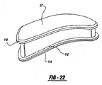
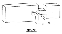
- An alternative locking mechanism between the pad member and housing member can be a tongue-and-groove relationship as shown in Figure 23 .
- Either the pad or the housing can include the tongue portion 122 and the other pad and housing members can include the groove 124.
- either of the locking members can include the tongue 122 and the other of the members being locked would include the groove 124.
- An alternative of this or the other locking mechanism shown is that the recess and/or pad can include multiple grooves or slots as well as multiple tongues.
- the various reeesses or pockets 50', 52, 58, 60 can be of different relative sizes and shapes.
- the upper housing member 12' may have a larger recess or pocket for seating a relatively larger one of said discs 28 and the lower housing member 14' may be include a smaller (larger and smaller referring to diameter of the annular recess) of the recesses or pockets for seating a relatively smaller one of the lower disc 30, thereby providing for an increased range of motion at the bearing surface interface.
- the outer surfaces 20, 22 of the various embodiments of the housing members 12, 14 can include flanges.
- the flanges or fins as they are sometimes referred to in the art, provide a mechanism for fixation to the intervertebral surfaces.
- Various embodiments, such as those shown in Figures 1 and 2 are dual fin constructs.
- Other embodiments, such as those shown in Figures 8 , 12, and 13 are single fin or single flange constructs.
- the surgeon can select various flange or fin configurations.
- the fins can be located in alternative positions, either centrally as shown in many of the Figures, or peripherally, as shown in Figure 14 , for a specific use with anterior extension plates, as with screw fixations.
- the flanges, such as flange 60"""' can include a bore 62 therethrough, which can be either a smooth surface or threaded depending on its intended use.
- the outer surfaces 20, 22 can be smooth, which allows for easier revision as it allows for minimal to no ingrowth or they can be textured. Texturing of the outer surfaces 20, 22 allows ingrowth for long-term fixation of the assembly 10.
- Porous coatings, plasma spray, grit blasting, machining, chemical etching, or milling are examples of techniques for creating ingrowth capable surfaces. Coatings that enhance bone growth can also be applied. Examples of such coatings arc hyroxyapatite and bone morphogenic proteins.
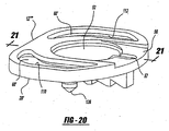
- Figures 20 and 21 provide structure for further rotational stability of the device in situ.
- the housing member 12"" includes pointed portions 126, 128 extending from the outer surface 20' thereof.
- the point members 126, 128 function in conjunction with the flange portion 61' to engage an opposing vertebral surface.
- the point portions 126, 128 being disposed radially peripherally from the centrally disposed flange 61' provide at least a three-point engagement of the vertebral surface thereby preventing rotation of the housing member 12"" relative thereto.
- the point portions 126, 128 can be in made in various configurations and extend various amounts from the outer surface 20' to be custom suited to a specific vertebrae surface shape.
- an assembled device 10 as shown in Figure 1 can be disposed between the intervertebral spaces during surgery, after calculation of space, depth, and height.
- opposing housing members 12, 14 can be disposed between the intervertebral spaces and pads 31 and disc members 24, 26 can be tested in situ prior to fixation thereof to allow for custom sizing.
- the artificial intervertebral disc 10 can be assembled in vivo by inserting upper and lower housing members 12, 14 into an intervertebral space and disposing cushioning pads 31 between the inner surfaces 16, 18 of the housing members 12, 14, thereby placing the pads in compression.
- the pair of disc members 28, 30 are inserted between the inner surfaces of the plates 16, 18.
- the disc members 28, 30 have abutting low friction surfaces 24, 26 therebetween.
- the disc members 28, 30 arc surrounded by the pads 31, whereby the disc members 28, 30 and pads 31 are under compressive forces and share such compressive forces.
- This step of the bearing surfaces 24, 26 and shock absorbing pads 31 sharing absorption of the compressive forces and limiting the relative movement of the housing members 12, 14 is an advantage not found in the prior art.
Description
- The present invention relates generally to a spinal implant assembly for implantation into the intervertebral space between adjacent vertebral bones to provide stabilization and continued postoperative flexibility and proper anatomical motion. More specifically, the present invention relates to an artificial intervertebral disc, sometimes referred to as an intervertebral spacer device, for functioning as a load sharing and bearing device for replacement of the damaged, decayed, or otherwise nonfunctioning intervertebral disc.
- The spine is a complex structure consisting of multiple flexible levels. Each level consists of a system of joints defined by adjacent vertebral bones. The system of joints includes intervertebral discs, which are a two-part structure. The disc consists of a nucleus and an annulus. The system allows motion while the facet joints add posterior stabilization to the spinal column. The disc allows motion and cushioning to the joint.
- The complex system of the joint is subjected to varying loads and problems over time, including disc degeneration due to a variety of reasons. Disc degeneration can be attributed to aging, damage due to excessive loading, trauma, and other anatomical issues. Facet joints of the structure can be compromised due to the same reasons, as well as due to arthritic changes. Severe joint degeneration and failure can often cause sufficient pain to require surgical intervention.
- The current standard method of treatment for severe pain caused by spine joint problems is fusion at the damaged level of the spine. The treatment, when successful, fuses the damaged section into a single mass of bone. The fusion of the joint eliminates motion of the joint, thereby reducing or eliminating pain at that level. Success rates for pain elimination are very high for this method of treatment. However, since the entire spine works as a system, fusion results in complications.
- Elimination of motion at the spine alters the biomechanics of the spine at every other level. If one level is fused, then loads are absorbed by one less disc into a system not designed for such change. Thus, the remaining discs must redistribute loads, each disc absorbing a greater load. In addition, the spine flexes to absorb loads. A fusion alters the means by which the spine flexes, which also increases the loads on the remaining healthy discs. In turn, it is well understood that a complication of fusion is that additional fusions may be required in the future as the other discs deteriorate due to the altered biomechanics of the spine. In other words, short-term pain relief is exchanged for long-term alterations of the spine, which, in turn, usually require further surgery.
- There are numerous prior art patents addressing the issue of disc replacement. The United States Patent Nos.
6,443,987 B1 and6,001,130, both to Bryan , disclose polymer composite structures for cushioning intervertebral loads. TheUnited States Patent Nos. 5,258,031 to Salib, et al. and5,314,477 to Marnay disclose ball and socket type implants addressing the issue of intervertebral mobility. These patents are exemplary of a first approach using an elastomer as a motion and dampening structure and a second approach utilizing a ball and socket joint to create a moving pivot joint. There are many variations on these concepts, which include mechanical springs and more complex structural mechanisms. A significant portion of the prior art addresses the issues of intervertebral motion but do not address anatomical loading considerations. - The current state of prior art artificial intervertebral discs are associated with various problems. For example, a number of implants constructed from polymers are of insufficient strength to work effectively in the higher loading areas, such as the lumbar spine. Such polymers often take compressive sets so that the original height of the implant decreases over time. A surgeon must either compensate for the compression by initially using a larger polymer prosthesis and estimate compression or use the appropriately sized polymer prosthesis and later surgically replace the same once the irreversible compression of the prosthesis is unacceptable.
- Implants constructed with ball and socket joints severely restrict or eliminate shock cushioning effect of a normal disc. This implant can provide motion, but biomechanically, the ball and socket joint negatively affects other healthy discs of the spine. The result can be long-term problems at other revels of the spine, as seen with the current treatment of fusion.
- Other implants, not discussed above, utilize bearing surfaces usually having polyethylene bearing against metal interfaces. Polyethylene as a bearing surface is problematic in large joint replacement due to the wear properties of the material. Since artificial discs arc intended to be implanted over long periods of time, such wear can be highly damaging to surrounding tissue and bonc.
- Tn view or the above, it is desirable to provide a solution to intervertebral disc replacement that restores motion to the damaged natural disc area while allowing for motion as well as cushioning and dampening, similar to the naturally occurring disc. In addition, it is preferable to allow such motion, cushioning, and dampening while preventing a polymer or elastomeric material from experiencing the relatively high compressive loads seen in the spine. It is also preferable to allow a bearing surface to share the spinal loads with the polymer and elastomeric material. Finally, it is preferable to control changes to the artificial motion intraoperatively to adjust for anatomical conditions.
- In accordance with the present invention, there is provided an artificial intervertebral disc including housing members having spaced inner surfaces facing each other and oppositely facing outer surfaces for engaging spaced apart vertebral surfaces. Bearing surfaces extend from each of the inner surfaces for engaging each other while allowing for low friction and compression resistant movement of the housing members relative to each other while under compression. A pair of load sharing pads peripherally disposed between the inner surfaces and about at least a portion of the bearing surfaces share absorption of compressive loads with the bearing surfaces while controllably limiting the relative movement of the housing members. An artificial intervertebral disc according to the preamble of claim 1 is disclosed in
FR 2694882 - The present invention can be used in a method of assembling an artificial intervertebral disc in vivo by inserting upper and lower housing members into an intervertebral space and disposing cushioning pads between the inner surfaces of the housing members, placing the pads in compression. A pair of disc members are inserted between the inner surfaces of the plates, the disc members having abutting low friction surfaces therebetween. The disc members effectively are surrounded by the pads whereby the disc members and pads are under compressive forces.
- Additionally, the present invention can be used in a method of separating opposing vertebrae at an intervertebral space includes the steps of engaging artificial bearing surfaces between the intervertebral spaces while allowing low friction and compression resistant movement of the bearing surfaces relative to each other, sharing absorption of the compressive forces with at least one load bearing pad disposed about at least a portion of the bearing surfaces, and limiting the relative movement of the bearing surfaces.
- Other advantages of the present invention can be readily appreciated as the same becomes better understood by reference to the following detailed description when considered in connection with the accompanying drawings wherein:
-
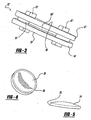
Figure 1 is a side perspective view of a preferred embodiment of the present invention; -
Figure 2 is a side exploded view of the embodiment shown inFigure 1 ; -
Figure 3 is a side perspective view of a second embodiment of the present invention: -
Figure 4 is a perspective view of a lower disc constructed in accordance with the present invention; -
Figure 5 is a side view of an upper disc constructed in accordance with the present invention; -
Figure 6 is a top perspective view of an upper housing member made in accordance with the present invention; -
Figure 7 is a top plan view of a lower housing member made in accordance with the present invention; -
Figure 8 is a side perspective view of a third embodiment of the present invention; -
Figure 9 is a perspective view of the present invention with the top housing member removed; -
Figure 10 is a perspective view of an alternative pad configuration of the present invention; - fïgure 11 is a perspective view of a an example of alternative pad member;
-
Figure 12 is a further alternative
example; -
Figure 13 is an exploded side perspective view of the embodiment shown inFigure 12 ; -
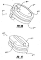
Figure 14 shows an alternative embodiment of the housing members of the present invention; -
Figure 15 shows a further alternative embodiment of the housing members of the present invention; -
Figure 16 is an exploded view of a further embodiment of the present invention demonstrating a bayonet type locking of a disc member to a housing member; -
Figure 17 is a perspective view of the disc member utilizing the bayonet locking mechanism to lock the disc member within a housing member; -
Figure 18 is an exploded view of a disc member and housing member showing a further embodiment of a locking mechanism for locking the disc member within the housing member; -
Figure 19 is a perspective view showing the disc member locked within the housing member; -
Figure 20 is a perspective view of the a further embodiment of the housing member; -
Figure 21 is a cross sectional view taken along line 21-21 inFigure 20 ; -
Figure 22 is a perspective view of a load sharing pad member including flanges for locking engagement in the recesses of the housing member shown inFigures 20 and21 ; and -
Figure 23 shows a further embodiment of a locking mechanism made in accordance with the present invention. - An artificial intervertebral disc constructed in accordance with the present invention is generally shown at 10 in the figures. Like structures of various embodiments are indicated by primed numerals in the Figures. The invention is an artificial intervertebral disc, sometimes referred to by other terminology in the prior art such as intervertebral spacer device, or spinal disc for replacement of a damaged disc in the spine. The invention restores motion to the damaged natural disc that allows for motion as well as cushioning and dampening. As described below in more detail, the present invention also allows changes to the artificial disc motion intraoperatively to adjust for specific anatomical conditions.
- Referring to the Figures, the
disc 10 includes an upper housing member generally shown at 12 and a lower housing member generally shown at 14. Thehousing members inner surfaces outer surfaces surfaces inner surfaces housing members disc members housing members housing members housing members discs - The upper and lower bearing surfaces 24, 26 engage each other when disposed correctly opposite each other. The configuration creates a three-dimensional bearing surface. As discussed below, the bearing surfaces 24, 26 are disposed on noncompressible discs or the like, thereby providing structure for absorbing compressive loads placed on the
outer surfaces housing members - Load sharing pads generally shown at 31 and specifically indicated as
pads Figures 1 and 2 are disposed between theinner surfaces housing members housing members load sharing pads device 10 to provide a system for motion and effective load distribution. The centralized low friction and compression resistant bearing surfaces 24, 26 allow full motion in multiple planes of the spine while the load distributing damper andcushioning pads pads pads pads housing members housing members pads pads - In view of the above, the system allows restoration of normal motion while maintaining load cushioning capabilities of a healthy disc. This is particularly apparent with motion of the spine. Any rotation of the upper and
lower housing members cushioning pads - As shown in the various figures, the bearing surfaces 24, 26 can include a concave surface portion on one of the upper or
lower disc members housing members load sharing pads load sharing pad bottom disc members - The
disc members housing members disc members housing members - The
load sharing pads pads Figures 1-3 . Alternatively, thedevice 10 can include four oppositely disposedpads Figure 10 . InFigure 11 , asingle pad 46 substantially covers thesurface 18"'' of thehousing member 14""' The pads can contour to the shape of the housing members such as shown inFigures 12, 13 , wherein thepad member 48 is an annular pad member disposed with aannular housing 12""", 14""". The selection ofsuch housing members pad members 31 can be determined based on the location of the placement of thedevice 10 as well as the spacing conditions between the vertebrae and load bearing necessities depending on the level of the spine being addressed. In other words, different shaped devices, such as the round shaped housing members shown inFigure 12 can be used for placement between smaller discs, such as cervical spines whereas more rectangular shapes, such as the housing members shown inFigures 1-11 can be used in between lumbar vertebrae. - The
load sharing pads 31, in which ever shape they are configured, are elastic for allowing relative twisting movement between thehousing members housing members housing members pad members 31 are compressible and stretchable, yet provide a self centering effect on the assembly with specific regard to thehousing members housing members pads 31 to act in such a way to counter the force, thus allowing a unique self-centering capability to theassembly 10. While in an ideal situation, wherein the patient's facets are uncompromised and ligamental balances are intact, this self-centering aspect may not be completely necessary. In other words, the patient's anatomy may still provide stabilization and specifically, ligaments may provide self-centering. However, ligamental imbalance, and damaged facets would normally make an artificial disc questionable, at best, with use of the current technology that is available. In such cases, having the ability to self-center and restrict motion (thepads 31 of the present invention are elastic and thus restrict motion by stretching and returning to rest), the possibility of extending indications to patients currently considered outside of the scope of artificial disc technology will be highly advantageous. - The
pads 31 of the present invention provide further advantages to the invention. A key advantage is the ability to adjust thepads 31 to patient and surgeon requirements. In such cases wherein range of motion needs to be restricted due to compromised facets, a harder, less elastic pad can be inserted between thehousing members assembly 10 to a patient's and surgeon's needs with multiple pads of different properties or materials. - The
pads 31 are made from a polymer or elastomer that allows deflection under load. Examples of such polymers and elastomers are silicone, polyurethane, and urethane composites. As discussed above with regard to flexibility or elasticity, the content and composition of thepads 31 are adjustable. A highly dense material creates a very rigid disc, while a very soft material creates a very free moving disc. The motion would be restricted in all planes of the pad depending upon these factors. Rotation is also restricted, as well as flexion or movement of the disc. The amount of compression possible is restricted or allowed according to the pads material properties. This is true of motion towards the back or side-to-side motion. Thus, thepads 31 are always in contact and always share the load, under any adjustment of relative positioning of thehousing members pads 31 automatically damper loads imposed by theartificial disc construct 10. - With specific regard to the flexibility or elasticity of the polymer or elastomer composition of the
pads 31, the pads can be selected from a composition having a durometer from 20 to 98 on the Shore OO Scale. Alternatively, thepads 31 can be selected from a composition having a durometer from 10 to 100 on the Shore A Scale. A further alternative is for thepads 31 to be selected from a composition having a durometer from 22 to 75 on the Shore D Scale. In any event, thepad members 31 can be selected during the operation and procedure by the clinician to suit a specific situation. Although thepad members 31 can be pre-inserted between thehousing members device 10 in situ, the various configurations of the present invention can allow for in situ replacement of thepad members 31 so as to custom select the flexibility or elasticity of the members. In this manner, thepad members 31 are custom designed for the individual environment of the intervertebral space into which the device is being disposed. - The
disc members pads 31 can be contained or locked in position in between thehousing members disc housing members disc members lower housing members -
Figures 1 and 2 show disc members lower recess 50 is shown inFigure 2 in an exploded view) in each of theinner surfaces housing members Figures 6 and 7 show plan views of a second embodiment of the housing member 12', 14', wherein eachrecess 50', 52 includes a rampedsurface recess portion 50', 52. The ramping 54, 56 allows access of thedisc members disc members - An alternative mechanical mechanism for locking the disc members within the housing members are shown in
Figure 16 . The representative housing member 12'" includes recess 52'. The recess 52' includes a substantially arcuateperipheral undergroove 70. The groove is defined by alip portion 72 including at least one and preferably at least twoopenings bayonet style flanges flanges recess flanges recesses Figure 17 . - A further alternative embodiment of the locking mechanism is shown in
Figures 18 and19 . The housing member 12'" includes a substantiallyarcuate recess 52" having anopen end portion 82 extending to anedge 84 of thehousing member 12"'. Therecess 52" includes alip portion 86 extending about a substantial portion thereof defining aninner groove 88 between the seatingsurface 90 of therecess 52" and thelip portion 86.Arm portions lip portion 86 but extend from and are separate fromperipheral ends arm portions recess 52". Each of thearms elbow portion arm portion surface 90, respectively. Thedisc member 28"' includes a substantially arcuate peripheral, radially outwardly extendingflange portion 104. Theflange portion 104 includes twoabutment edges flange 104 and disc member 28''' are disposed within the annular recess orgroove 88, deflecting outwardly thearms recess 52", as shown inFigure 19 , theelbows disc member 28"' in place. Outward deflection of thearms disc member 28"' from locked engagement to provide for further adjustment of the selection of the disc member during an operation procedure. - Also, as best shown in
Figures 6 and 7 , thepads members 31 can be disposed inrecesses pad members 31 to the housing members 12', 14' by use of mechanical mechanisms and/or various adhesives, such as cyanoarylates, urethanes, and other medical grade adhesives. This list of adhesives, as with other listings of ingredients in the present application, is merely exemplary and not meant to be exhaustive. - Examples of mechanical mechanisms for locking the
pad members 31 into recesses in the housing members are shown inFigures 20-23 . One such mechanism is an undercut locking mechanism shown inFigures 20 - 22 .Housing member 12"" includes acentral recess 52 such as shown inFigure 6 having aramp portion 56. Theramp portion 56 includes a centrally locatedtongue groove 57 allowing for the insertion of a spatula type device under a disc member disposed within therecess 52 for releasing the disc member from the recess, similar to the use of a shoehorn type mechanism. Recesses 60' include undercutrecesses peripheral flange portion 114 extending from anedge 116 of a pad member 31'. Since the pad member is made from a deflectable material, theflange portion 114 can be force-fit into and seated within the undercut 110, 112. The undercut locking mechanism effectively prevents the pad member 31' from disengagement with thehousing member 12"" in situ. Of course, theupper flange 118 would be locked within a similar undercut locking detail of recesses within the opposing housing member (not shown). - An alternative locking mechanism between the pad member and housing member can be a tongue-and-groove relationship as shown in
Figure 23 . Either the pad or the housing can include thetongue portion 122 and the other pad and housing members can include thegroove 124. In other words, either of the locking members can include thetongue 122 and the other of the members being locked would include thegroove 124. An alternative of this or the other locking mechanism shown is that the recess and/or pad can include multiple grooves or slots as well as multiple tongues. - The various reeesses or pockets 50', 52, 58, 60 can be of different relative sizes and shapes. For example, the upper housing member 12' may have a larger recess or pocket for seating a relatively larger one of said
discs 28 and the lower housing member 14' may be include a smaller (larger and smaller referring to diameter of the annular recess) of the recesses or pockets for seating a relatively smaller one of thelower disc 30, thereby providing for an increased range of motion at the bearing surface interface. - The various Figure show that the
outer surfaces housing members Figures 1 and 2 are dual fin constructs. Other embodiments, such as those shown inFigures 8 ,12, and 13 are single fin or single flange constructs. Depending upon the nature of the surfaces to which theouter surfaces Figure 14 , for a specific use with anterior extension plates, as with screw fixations. The flanges, such asflange 60"""' can include abore 62 therethrough, which can be either a smooth surface or threaded depending on its intended use. - The
outer surfaces outer surfaces assembly 10. Porous coatings, plasma spray, grit blasting, machining, chemical etching, or milling are examples of techniques for creating ingrowth capable surfaces. Coatings that enhance bone growth can also be applied. Examples of such coatings arc hyroxyapatite and bone morphogenic proteins. -
Figures 20 and21 provide structure for further rotational stability of the device in situ. Thehousing member 12"" includes pointedportions point members point portions housing member 12"" relative thereto. Of course, thepoint portions - Various methods can be utilized for insertion of the present invention in situ. For example, an assembled
device 10 as shown inFigure 1 , can be disposed between the intervertebral spaces during surgery, after calculation of space, depth, and height. Alternatively, opposinghousing members pads 31 anddisc members intervertebral disc 10 can be assembled in vivo by inserting upper andlower housing members cushioning pads 31 between theinner surfaces housing members disc members plates disc members disc members pads 31, whereby thedisc members pads 31 are under compressive forces and share such compressive forces. This step of the bearing surfaces 24, 26 andshock absorbing pads 31 sharing absorption of the compressive forces and limiting the relative movement of thehousing members
Claims (38)
- An artificial intervertebral disc (10) comprising:housing members (12,14) including spaced inner surfaces (16,18) facing each other and oppositely facing outer surfaces (20,22) for engaging spaced apart intervertebral surfaces;bearing surfaces (24,26) extending from each of said inner surfaces for engaging each other while allowing for low friction and compression resistance relative to each other while under compression; andload sharing means (31) disposed between said inner surfaces and about at least a portion of said bearing surfaces for sharing absorption of compressive loads with said bearing surfaces while limiting the relative movement of said housing members;characterised in that said load sharing means includes at least two pad members (32, 34, 38, 40, 42, 44, 46, 48) disposed peripherally relative to said bearing surfaces and between said inner surfaces.
- An artificial intervertebral disc according to claim 1, wherein said bearing surfaces include a concave surface portion extending from one of said inner surfaces and a convex surface portion extending from the other of said inner surfaces (24,26) and seated against said concave surface portion for sliding movement relative thereto effectively resulting in relative pivoting motion of said housing members which can compress at least a portion of said load sharing means while distending at least a portion of said load sharing means.
- An artificial intervertebral disc according to claim 1 or claim 2, wherein said load sharing means arc elastic for allowing relative twisting movement between said housing members effecting relative three dimensional movement between said housing members while limiting said movement and preventing contact between said housing members except for said bearing surfaces.
- An artificial intervertebral disc according to any of claims 1 to 3, including a pair of disc members (28,30), each of said disc members including one of said bearing surfaces (24,26), said inner surfaces of said housing members including disc seating means for seating one of said disc members therein in opposing relationship of the other of said disc members seated in said seating means of the other of said housing members.
- An artificial intervertebral disc according to claim 4, wherein said seating means includes a pocket (50,52) recessed into each of said inner surfaces of said housing members.
- An artificial intervertebral disc according to claim 5, including locking means for selectively preventing relative movement of said disc member and said housing member once said disc member is seated in said pocket.
- An artificial intervertebral disc according to claim 6, wherein said locking means includes a press fit taper in a wall of said pocket.
- An artificial intervertebral disc according to claim 6, wherein said locking means includes a retaining ring operatively connected to said pocket.
- An artificial intervertebral disc according to claim 6, wherein said locking means includes at least one undercut groove (70,88) disposed about said pocket and said disc member includes at least one radially outwardly extending flange (78,80,104) for locking engagement within said undercut groove.
- An artificial intervertebral disc according to claim 9 wherein said flange includes at least one radially outwardly extending bayonet portion (78,80).
- An artificial intervertebral disc according to claim 6 wherein said locking means includes at least one undercut groove (124) disposed about a radial periphery of said disc member and said pocket of said housing member includes at least one radially inwardly extending flange (122) for locking engagement within said undercut groove.
- An artificial intervertebral disc according to claim 5, including a ramped surface (54,56) extending from an edge of said inner surface of at least one of said housing members to said pocket allowing for lateral insertion of said disc members into said pockets when said housing members are disposed in spaced relationship to each other in an intervertebral space.
- An artificial intervertébral disc according to claim 5 further defined as said housing members being an upper member (12) and a lower member (14) for relative positioning between vertebrae, said upper member including a relatively larger one of said pockets for seating a relatively larger one of said disc members having a concave surface and said lower member including a relatively smaller pocket for seating a relatively smaller one of said discs thereby providing an increased range of motion at the bearing surface interface.
- An artificial intervertebral disc according to any preceding claim, wherein said disc members are made from a composition selected from the group including ceramics, plastics, and metal bearing materials.
- An artificial intervertebral disc according to any preceding claim, wherein at least one pad member is disposed and retained between said inner surfaces of said housing members and has cushioning and elastic properties for countering and thereby self centering against forces caused by relative movement of said housing member while under compressive forces are applied to said outer surfaces of said housing members.
- An artificial intervertebral disc according to claim 15, wherein said housing members include seating means for seating said pad member between said inner surfaces.
- An artificial intervertebral disc according to claim 16, wherein said seating means includes at least one pocket (58,60) recessed into said inner surface of said housing member for seating a portion of said pad member therein.
- An artificial intervertebral disc according to claim 17, including adhering means for fixedly adhering said pad member within said pocket.
- An artificial intervertebral disc according to claim 17, wherein said pocket includes at least one undercut recess (110,112) about at least a portion thereof and said pad members include at least one outwardly extending flange portion (114) for being seated within said recess to lock said pad members in a desired position relative to said housing member.
- An artificial intervertebral disc according to claim 17 wherein said pad member includes at least one peripherally located recess (124) about an edge portion thereof and said pocket includes at least one inwardly extending flange portion (122) including at least one inwardly extending flange portion for being seated within said recess to lock said pad member in a desired position relative to said housing member.
- An artificial intervertebral disc according to any of claims 15 to 20, wherein said pad members are selected from a composition having a durometer in the range of 20 to 98 on the Shore OO Scale.
- An artificial intervertebral disc according to any of claims 15 to 20, wherein said pad members are selected from a composition having a durometer of 10 to 100 on the Shore A Scale.
- An artificial intervertebral disc according to any of claims 15 to 20, wherein said pad members arc selected from a composition having a durometer of 22 to 75 on the Shore D Scale.
- An artificial intervertebral disc according to any of claims 15 to 23, wherein the pads are made from a composition selected from the group including polymers and elastomers.
- An artificial intervertebral disc according to claim 24, wherein the pads are made from a composition selected from the group including silicone, polyurethane, and urethane composites, plastics, polymers, and elastomers.
- An artificial intervertebral disc according to any preceding claim, wherein said housing members are constructed from a composition selected from the group including metals, ceramics, and plastics.
- An artificial intervertebral disc according to any preceding claim, wherein said outer surface of said housing member includes a surface texture for accepting bone growth therein.
- An artificial intervertebral disc according to claim 27, wherein said surface texture is selected from the group including physically roughened, porous coated, and plasma coated surfaces.
- An artificial intervertebral disc according to claim 27 further including bone growth inducing means disposed on said outer surface of said housing member for increasing bone growth on the said outer surface.
- An artificial intervertebral disc according to claim 29, wherein said bone growth inducing means is a coating selected from the group including hyroxyapatite and bone morphogenic proteins.
- An artificial intervertebral disc according to claim 1, including at least one flange (60) extending from said outer surface for fixing said housing members to a vertebral surface.
- An artificial intervertebral disc according to claim 1, wherein at least one of said outer surfaces includes a recessed portion.
- An artificial intervertebral disc according to claim 32 further including a porous coating disposed within said recess.
- An artificial intervertebral disc according to claim 1 wherein the bearing surfaces are noncompressible for allowing motion between two bearing surfaces while limiting compression thereof, and wherein the load sharing means have compression absorbing properties for sharing compressive forces with said bearing surface means while limiting motion of said bearing surface means.
- An artificial intervertebral disc according to claim 1, wherein said bearing surfaces are integral with a pair of disc members (28,30).
- An artificial intervertebral disc according to claim 1, wherein each housing member comprises a recess (260) and wherein each pad member comprises a body portion and at least one peripheral flange portion (114) for engaging one of said recesses (60).
- An artificial intervertebral disc according to claim 1, wherein each pad member comprises a body portion and a groove (124), and wherein each housing member comprises a tongue portion (122) for engaging one of the pad members.
- An artificial intervertebral disc according to claim 1, wherein each housing member includes one centrally located recess portion (50,52) and at least one other recess portion (58,60) disposed peripherally relative to said centrally located recess portion.
Applications Claiming Priority (2)
| Application Number | Priority Date | Filing Date | Title |
|---|---|---|---|
| US10/430,861 US7105024B2 (en) | 2003-05-06 | 2003-05-06 | Artificial intervertebral disc |
| EP04252415A EP1475059A3 (en) | 2003-05-06 | 2004-04-26 | Artificial intervertebral disc |
Related Parent Applications (2)
| Application Number | Title | Priority Date | Filing Date |
|---|---|---|---|
| EP04252415.7 Division | 2004-04-26 | ||
| EP04252415A Division EP1475059A3 (en) | 2003-05-06 | 2004-04-26 | Artificial intervertebral disc |
Publications (3)
| Publication Number | Publication Date |
|---|---|
| EP1905390A2 EP1905390A2 (en) | 2008-04-02 |
| EP1905390A3 EP1905390A3 (en) | 2008-04-16 |
| EP1905390B1 true EP1905390B1 (en) | 2013-07-10 |
Family
ID=32990525
Family Applications (2)
| Application Number | Title | Priority Date | Filing Date |
|---|---|---|---|
| EP04252415A Withdrawn EP1475059A3 (en) | 2003-05-06 | 2004-04-26 | Artificial intervertebral disc |
| EP07018677.0A Expired - Lifetime EP1905390B1 (en) | 2003-05-06 | 2004-04-26 | Artificial intervertebral disc |
Family Applications Before (1)
| Application Number | Title | Priority Date | Filing Date |
|---|---|---|---|
| EP04252415A Withdrawn EP1475059A3 (en) | 2003-05-06 | 2004-04-26 | Artificial intervertebral disc |
Country Status (6)
| Country | Link |
|---|---|
| US (4) | US7105024B2 (en) |
| EP (2) | EP1475059A3 (en) |
| JP (2) | JP4651306B2 (en) |
| AU (1) | AU2004201685B2 (en) |
| CA (1) | CA2466394C (en) |
| ES (1) | ES2430366T3 (en) |
Cited By (2)
| Publication number | Priority date | Publication date | Assignee | Title |
|---|---|---|---|---|
| US10022245B2 (en) | 2012-12-17 | 2018-07-17 | DePuy Synthes Products, Inc. | Polyaxial articulating instrument |
| US11690734B2 (en) | 2017-08-14 | 2023-07-04 | DePuy Synthes Products, Inc. | Intervertebral implant inserters and related methods |
Families Citing this family (117)
| Publication number | Priority date | Publication date | Assignee | Title |
|---|---|---|---|---|
| US7494507B2 (en) | 2000-01-30 | 2009-02-24 | Diamicron, Inc. | Articulating diamond-surfaced spinal implants |
| US7060100B2 (en) * | 1999-10-08 | 2006-06-13 | Ferree Bret A | Artificial disc and joint replacements with modular cushioning components |
| FR2824261B1 (en) | 2001-05-04 | 2004-05-28 | Ldr Medical | INTERVERTEBRAL DISC PROSTHESIS AND IMPLEMENTATION METHOD AND TOOLS |
| ES2287460T3 (en) * | 2002-03-11 | 2007-12-16 | Spinal Concepts Inc. | INSTRUMENTATION TO IMPLEMENT COLUMN IMPLANTS. |
| EP1542626B1 (en) | 2002-08-15 | 2012-09-26 | Synthes GmbH | Controlled artificial intervertebral disc implant |
| US7833246B2 (en) | 2002-10-29 | 2010-11-16 | Kyphon SÀRL | Interspinous process and sacrum implant and method |
| FR2846550B1 (en) | 2002-11-05 | 2006-01-13 | Ldr Medical | INTERVERTEBRAL DISC PROSTHESIS |
| US7105024B2 (en) * | 2003-05-06 | 2006-09-12 | Aesculap Ii, Inc. | Artificial intervertebral disc |
| US7291173B2 (en) * | 2003-05-06 | 2007-11-06 | Aesculap Ii, Inc. | Artificial intervertebral disc |
| DE20308171U1 (en) * | 2003-05-21 | 2003-07-31 | Aesculap Ag & Co Kg | Vertebral body replacement implant |
| US7695515B2 (en) * | 2003-07-15 | 2010-04-13 | Spinal Generations, Llc | Spinal disc prosthesis system |
| FR2858546B1 (en) * | 2003-08-04 | 2006-04-28 | Spine Next Sa | INTERVERTEBRAL DISC PROSTHESIS |
| DE10337088A1 (en) * | 2003-08-12 | 2005-03-10 | Biedermann Motech Gmbh | Placeholder for vertebral bodies or intervertebral discs |
| US7794465B2 (en) * | 2003-09-10 | 2010-09-14 | Warsaw Orthopedic, Inc. | Artificial spinal discs and associated implantation instruments and methods |
| ATE508713T1 (en) | 2003-11-18 | 2011-05-15 | Zimmer Gmbh | DISC IMPLANT |
| US7670377B2 (en) * | 2003-11-21 | 2010-03-02 | Kyphon Sarl | Laterally insertable artifical vertebral disk replacement implant with curved spacer |
| US7503935B2 (en) * | 2003-12-02 | 2009-03-17 | Kyphon Sarl | Method of laterally inserting an artificial vertebral disk replacement with translating pivot point |
| FR2865629B1 (en) | 2004-02-04 | 2007-01-26 | Ldr Medical | INTERVERTEBRAL DISC PROSTHESIS |
| RU2354334C2 (en) | 2004-02-04 | 2009-05-10 | Лдр Медикаль | Intervertebral disc prosthesis |
| FR2869528B1 (en) * | 2004-04-28 | 2007-02-02 | Ldr Medical | INTERVERTEBRAL DISC PROSTHESIS |
| DE202004009542U1 (en) * | 2004-06-16 | 2004-08-12 | Aesculap Ag & Co. Kg | Artificial intervertebral disk, comprising core with intensely curved upper and less curved lower surface |
| US8172904B2 (en) | 2004-06-30 | 2012-05-08 | Synergy Disc Replacement, Inc. | Artificial spinal disc |
| ES2398085T3 (en) | 2004-06-30 | 2013-03-13 | Synergy Disc Replacement Inc. | Artificial intervertebral disc |
| US9237958B2 (en) | 2004-06-30 | 2016-01-19 | Synergy Disc Replacement Inc. | Joint prostheses |
| WO2006058221A2 (en) | 2004-11-24 | 2006-06-01 | Abdou Samy M | Devices and methods for inter-vertebral orthopedic device placement |
| JP4601051B2 (en) * | 2004-12-20 | 2010-12-22 | 株式会社ユニバーサルエンターテインメント | Gaming chips |
| FR2879436B1 (en) | 2004-12-22 | 2007-03-09 | Ldr Medical | INTERVERTEBRAL DISC PROSTHESIS |
| JP2008526373A (en) * | 2005-01-08 | 2008-07-24 | アルファスパイン インコーポレイテッド | Modular disk device |
| US7690381B2 (en) * | 2005-02-10 | 2010-04-06 | Depuy Spine, Inc. | Intervertebral prosthetic disc and method for installing using a guidewire |
| US8911498B2 (en) | 2005-02-10 | 2014-12-16 | DePuy Synthes Products, LLC | Intervertebral prosthetic disc |
| EP1858809A1 (en) * | 2005-03-02 | 2007-11-28 | St. Jude Medical AB | Metal-vanadium-oxide-product and producing process |
| US7267690B2 (en) | 2005-03-09 | 2007-09-11 | Vertebral Technologies, Inc. | Interlocked modular disc nucleus prosthesis |
| FR2885294B1 (en) * | 2005-05-03 | 2008-04-04 | Jerome Levieux | INTERVERTEBRAL DISC PROSTHESIS |
| DE102005025685B4 (en) * | 2005-06-03 | 2015-05-21 | Mathys Ag Bettlach | Intervertebral disc implant |
| US8394142B2 (en) * | 2005-06-13 | 2013-03-12 | Synthes Usa, Llc | Customizing an intervertebral implant |
| FR2887435B1 (en) * | 2005-06-24 | 2007-10-05 | Abbott Spine Sa | INTERVERTEBRAL DISC PROSTHESIS |
| FR2887762B1 (en) | 2005-06-29 | 2007-10-12 | Ldr Medical Soc Par Actions Si | INTERVERTEBRAL DISC PROSTHESIS INSERTION INSTRUMENTATION BETWEEN VERTEBRATES |
| CN102670334A (en) * | 2005-07-06 | 2012-09-19 | 弗朗茨·小科弗 | Intervertebral disc prosthesis |
| HK1121665A1 (en) | 2005-07-06 | 2009-04-30 | Franz Jun Copf | Intervertebral disc prosthesis |
| FR2891135B1 (en) | 2005-09-23 | 2008-09-12 | Ldr Medical Sarl | INTERVERTEBRAL DISC PROSTHESIS |
| US20070093900A1 (en) * | 2005-09-26 | 2007-04-26 | Williams Lytton A | Modular articulating and fusion spinal disc implant system |
| US7927373B2 (en) | 2005-10-31 | 2011-04-19 | Depuy Spine, Inc. | Intervertebral disc prosthesis |
| US7967862B2 (en) * | 2005-11-23 | 2011-06-28 | Warsaw Orthopedic, Inc. | Posterior articular disc and method for implantation |
| FR2893838B1 (en) | 2005-11-30 | 2008-08-08 | Ldr Medical Soc Par Actions Si | PROSTHESIS OF INTERVERTEBRAL DISC AND INSTRUMENTATION OF INSERTION OF THE PROSTHESIS BETWEEN VERTEBRATES |
| US20070191860A1 (en) * | 2006-01-30 | 2007-08-16 | Sdgi Holdings, Inc. | Intervertebral prosthetic disc inserter |
| US20070179614A1 (en) * | 2006-01-30 | 2007-08-02 | Sdgi Holdings, Inc. | Intervertebral prosthetic disc and method of installing same |
| US8556973B2 (en) * | 2006-02-10 | 2013-10-15 | DePuy Synthes Products, LLC | Intervertebral disc prosthesis having multiple bearing surfaces |
| US8137404B2 (en) * | 2006-03-28 | 2012-03-20 | Depuy Spine, Inc. | Artificial disc replacement using posterior approach |
| US20070233244A1 (en) * | 2006-03-28 | 2007-10-04 | Depuy Spine, Inc. | Artificial Disc Replacement Using Posterior Approach |
| US8282641B2 (en) | 2006-03-28 | 2012-10-09 | Depuy Spine, Inc. | Methods and instrumentation for disc replacement |
| US8348978B2 (en) | 2006-04-28 | 2013-01-08 | Warsaw Orthopedic, Inc. | Interosteotic implant |
| US7846185B2 (en) | 2006-04-28 | 2010-12-07 | Warsaw Orthopedic, Inc. | Expandable interspinous process implant and method of installing same |
| US8252031B2 (en) | 2006-04-28 | 2012-08-28 | Warsaw Orthopedic, Inc. | Molding device for an expandable interspinous process implant |
| US8105357B2 (en) | 2006-04-28 | 2012-01-31 | Warsaw Orthopedic, Inc. | Interspinous process brace |
| US8048118B2 (en) | 2006-04-28 | 2011-11-01 | Warsaw Orthopedic, Inc. | Adjustable interspinous process brace |
| US20080021457A1 (en) * | 2006-07-05 | 2008-01-24 | Warsaw Orthopedic Inc. | Zygapophysial joint repair system |
| EP2073762B1 (en) * | 2006-08-22 | 2011-04-06 | Synthes GmbH | Total disc replacement device |
| US8745845B2 (en) | 2006-11-07 | 2014-06-10 | Dc Devices, Inc. | Methods for mounting a prosthesis onto a delivery device |
| EP2097012A4 (en) | 2006-11-07 | 2012-08-15 | David Stephen Celermajer | Devices and methods for the treatment of heart failure |
| US9232997B2 (en) | 2006-11-07 | 2016-01-12 | Corvia Medical, Inc. | Devices and methods for retrievable intra-atrial implants |
| US10413284B2 (en) | 2006-11-07 | 2019-09-17 | Corvia Medical, Inc. | Atrial pressure regulation with control, sensing, monitoring and therapy delivery |
| US20110257723A1 (en) | 2006-11-07 | 2011-10-20 | Dc Devices, Inc. | Devices and methods for coronary sinus pressure relief |
| US9737414B2 (en) | 2006-11-21 | 2017-08-22 | Vertebral Technologies, Inc. | Methods and apparatus for minimally invasive modular interbody fusion devices |
| US8715352B2 (en) | 2006-12-14 | 2014-05-06 | Depuy Spine, Inc. | Buckling disc replacement |
| US20080177389A1 (en) * | 2006-12-21 | 2008-07-24 | Rob Gene Parrish | Intervertebral disc spacer |
| EP3130317B1 (en) | 2007-02-09 | 2021-11-10 | Dimicron, Inc. | Multi-lobe artificial spine joint |
| US8465546B2 (en) | 2007-02-16 | 2013-06-18 | Ldr Medical | Intervertebral disc prosthesis insertion assemblies |
| FR2916956B1 (en) | 2007-06-08 | 2012-12-14 | Ldr Medical | INTERSOMATIC CAGE, INTERVERTEBRAL PROSTHESIS, ANCHORING DEVICE AND IMPLANTATION INSTRUMENTATION |
| EP2016923A1 (en) * | 2007-07-14 | 2009-01-21 | Gerd Axel Dr. Walther | Joint prosthesis |
| WO2009055478A1 (en) | 2007-10-22 | 2009-04-30 | Spinalmotion, Inc. | Vertebral body replacement and method for spanning a space formed upon removal of a vertebral body |
| CN101909549B (en) | 2007-10-25 | 2014-07-23 | 奈尔·杜加尔 | Systems and methods for vertebral disc replacement |
| US8758439B2 (en) | 2007-11-19 | 2014-06-24 | Linares Medical Devices, Llc | Spine support implant including inter vertebral insertable fluid ballastable insert and inter-vertebral web retaining harnesses |
| US20090131984A1 (en) * | 2007-11-19 | 2009-05-21 | Linares Miguel A | Spine support implant including inter vertebral insertable fluid ballastable insert and inter-vertebral web retaining harnesses |
| US8888850B2 (en) * | 2007-11-19 | 2014-11-18 | Linares Medical Devices, Llc | Combination spacer insert and support for providing inter-cervical vertebral support |
| US8216314B2 (en) | 2008-02-13 | 2012-07-10 | Marc Richelsoph | Distractable spinal implant assembly |
| US20090248161A1 (en) * | 2008-03-20 | 2009-10-01 | K2M, Inc. | Artificial disc replacement device |
| EP2116211A1 (en) * | 2008-05-05 | 2009-11-11 | Christian Röbling | Intervertebral prosthesis |
| DE102008032691A1 (en) | 2008-07-03 | 2010-01-07 | Aesculap Ag | Intervertebral disc prosthesis system |
| US9757107B2 (en) | 2009-09-04 | 2017-09-12 | Corvia Medical, Inc. | Methods and devices for intra-atrial shunts having adjustable sizes |
| US9028553B2 (en) | 2009-11-05 | 2015-05-12 | DePuy Synthes Products, Inc. | Self-pivoting spinal implant and associated instrumentation |
| US8764806B2 (en) | 2009-12-07 | 2014-07-01 | Samy Abdou | Devices and methods for minimally invasive spinal stabilization and instrumentation |
| AU2011210741B2 (en) | 2010-01-29 | 2013-08-15 | Corvia Medical, Inc. | Devices and methods for reducing venous pressure |
| EP2538885A1 (en) | 2010-02-26 | 2013-01-02 | spontech spine intelligence group AG | Computer program for spine mobility simulation and spine simulation method |
| US9301853B2 (en) | 2010-04-09 | 2016-04-05 | DePuy Synthes Products, Inc. | Holder for implantation and extraction of prosthesis |
| US8858636B2 (en) | 2010-04-09 | 2014-10-14 | DePuy Synthes Products, LLC | Intervertebral implant |
| US9358122B2 (en) | 2011-01-07 | 2016-06-07 | K2M, Inc. | Interbody spacer |
| EP3275390B1 (en) | 2011-02-10 | 2019-06-19 | Corvia Medical, Inc. | Apparatus to create and maintain an intra-atrial pressure relief opening |
| JP5664391B2 (en) * | 2011-03-23 | 2015-02-04 | 株式会社豊田中央研究所 | Dummy equipment |
| US8845728B1 (en) | 2011-09-23 | 2014-09-30 | Samy Abdou | Spinal fixation devices and methods of use |
| WO2013096965A1 (en) | 2011-12-22 | 2013-06-27 | Dc Devices, Inc. | Methods and devices for intra-atrial devices having selectable flow rates |
| US9005155B2 (en) | 2012-02-03 | 2015-04-14 | Dc Devices, Inc. | Devices and methods for treating heart failure |
| US20130226240A1 (en) | 2012-02-22 | 2013-08-29 | Samy Abdou | Spinous process fixation devices and methods of use |
| US9510953B2 (en) | 2012-03-16 | 2016-12-06 | Vertebral Technologies, Inc. | Modular segmented disc nucleus implant |
| US10588611B2 (en) | 2012-04-19 | 2020-03-17 | Corvia Medical Inc. | Implant retention attachment and method of use |
| US9649480B2 (en) | 2012-07-06 | 2017-05-16 | Corvia Medical, Inc. | Devices and methods of treating or ameliorating diastolic heart failure through pulmonary valve intervention |
| US9198767B2 (en) | 2012-08-28 | 2015-12-01 | Samy Abdou | Devices and methods for spinal stabilization and instrumentation |
| US9320617B2 (en) | 2012-10-22 | 2016-04-26 | Cogent Spine, LLC | Devices and methods for spinal stabilization and instrumentation |
| US9775636B2 (en) | 2013-03-12 | 2017-10-03 | Corvia Medical, Inc. | Devices, systems, and methods for treating heart failure |
| US9655735B2 (en) * | 2013-03-15 | 2017-05-23 | Atlas Spine, Inc. | Spinal disc prosthesis |
| US10603187B2 (en) * | 2013-07-17 | 2020-03-31 | Aesculap Implant Systems, Llc | Spinal interbody device, system and method |
| EP3726213A1 (en) | 2013-08-19 | 2020-10-21 | Singular Bio Inc. | Assays for single molecule detection and use thereof |
| US10675450B2 (en) | 2014-03-12 | 2020-06-09 | Corvia Medical, Inc. | Devices and methods for treating heart failure |
| EP3171786B1 (en) | 2014-07-23 | 2020-05-13 | Corvia Medical, Inc. | Devices for treating heart failure |
| US9561113B2 (en) * | 2014-12-23 | 2017-02-07 | Globus Medical, Inc. | Vertebral implants and methods for installation thereof |
| US11739371B2 (en) | 2015-02-18 | 2023-08-29 | Invitae Corporation | Arrays for single molecule detection and use thereof |
| EP3064175B1 (en) * | 2015-03-03 | 2023-11-01 | SMed - TA/TD LLC | Orthopaedic implant with porous structural member |
| US10857003B1 (en) | 2015-10-14 | 2020-12-08 | Samy Abdou | Devices and methods for vertebral stabilization |
| US9950156B2 (en) | 2016-09-13 | 2018-04-24 | Rainbow Medical Ltd. | Disc therapy |
| US10231849B2 (en) | 2016-10-13 | 2019-03-19 | Warsaw Orthopedic, Inc. | Surgical instrument system and method |
| US10973648B1 (en) | 2016-10-25 | 2021-04-13 | Samy Abdou | Devices and methods for vertebral bone realignment |
| US10744000B1 (en) | 2016-10-25 | 2020-08-18 | Samy Abdou | Devices and methods for vertebral bone realignment |
| US10966843B2 (en) | 2017-07-18 | 2021-04-06 | DePuy Synthes Products, Inc. | Implant inserters and related methods |
| US11678995B2 (en) | 2018-07-20 | 2023-06-20 | Fellowship Of Orthopaedic Researchers, Inc. | Magnetic intervertebral disc replacement devices and methods thereof |
| US11179248B2 (en) | 2018-10-02 | 2021-11-23 | Samy Abdou | Devices and methods for spinal implantation |
| US11123197B2 (en) | 2019-09-03 | 2021-09-21 | Rainbow Medical Ltd. | Hydropneumatic artificial intervertebral disc |
| US11452618B2 (en) | 2019-09-23 | 2022-09-27 | Dimicron, Inc | Spinal artificial disc removal tool |
| US11291553B2 (en) * | 2020-03-05 | 2022-04-05 | Phoenyx Spinal Technologies, Inc. | Interlocking spinal disc prosthetic |
Family Cites Families (192)
| Publication number | Priority date | Publication date | Assignee | Title |
|---|---|---|---|---|
| DE900094C (en) | 1951-08-17 | 1953-12-21 | Basf Ag | Process for the preparation of oximes of cycloaliphatic ketones |
| US3426364A (en) * | 1966-08-25 | 1969-02-11 | Colorado State Univ Research F | Prosthetic appliance for replacing one or more natural vertebrae |
| SE391122B (en) * | 1971-01-25 | 1977-02-07 | Cutter Lab | PROTESTS IN THE FORM OF A SPINE BONIC DISC AND PROCEDURES FOR MANUFACTURE THEREOF |
| DE2263842A1 (en) | 1972-12-28 | 1974-07-04 | Hoffmann Daimler Siegfried Dr | DISC PROTHESIS |
| US3875595A (en) * | 1974-04-15 | 1975-04-08 | Edward C Froning | Intervertebral disc prosthesis and instruments for locating same |
| CH640131A5 (en) | 1979-10-03 | 1983-12-30 | Sulzer Ag | Complete intervertebral prosthesis |
| US4309777A (en) * | 1980-11-13 | 1982-01-12 | Patil Arun A | Artificial intervertebral disc |
| DE3320162A1 (en) * | 1983-06-03 | 1984-12-06 | Olbo Textilwerke Gmbh, 5650 Solingen | CORD TISSUE FOR AIR TIRES |
| ATE44871T1 (en) * | 1984-09-04 | 1989-08-15 | Univ Berlin Humboldt | DISC PROSTHESIS. |
| GB8620937D0 (en) * | 1986-08-29 | 1986-10-08 | Shepperd J A N | Spinal implant |
| CA1283501C (en) | 1987-02-12 | 1991-04-30 | Thomas P. Hedman | Artificial spinal disc |
| DE3707918C2 (en) * | 1987-03-12 | 1996-01-25 | Fichtel & Sachs Ag | Two-disc clutch with controlled forced lifting |
| US4863477A (en) * | 1987-05-12 | 1989-09-05 | Monson Gary L | Synthetic intervertebral disc prosthesis |
| FR2636683B2 (en) * | 1988-02-26 | 1990-12-28 | Berger Michel | HANGING ASSEMBLY SYSTEM HAVING HANGING ELEMENTS FORMED BY CURVILINE RIBS PROVIDED WITH ELASTICALLY DEFORMABLE LIPS |
| DE3809793A1 (en) | 1988-03-23 | 1989-10-05 | Link Waldemar Gmbh Co | SURGICAL INSTRUMENT SET |
| DE8807485U1 (en) * | 1988-06-06 | 1989-08-10 | Mecron Medizinische Produkte Gmbh, 1000 Berlin, De | |
| US4911718A (en) * | 1988-06-10 | 1990-03-27 | University Of Medicine & Dentistry Of N.J. | Functional and biocompatible intervertebral disc spacer |
| US5037438A (en) * | 1989-07-25 | 1991-08-06 | Richards Medical Company | Zirconium oxide coated prosthesis for wear and corrosion resistance |
| DE8912648U1 (en) * | 1989-10-23 | 1990-11-22 | Mecron Medizinische Produkte Gmbh, 1000 Berlin, De | |
| US5545227A (en) * | 1989-12-21 | 1996-08-13 | Smith & Nephew Richards, Inc. | Biocompatible low modulus medical implants |
| DE9000094U1 (en) | 1990-01-04 | 1991-01-31 | Mecron Medizinische Produkte Gmbh, 1000 Berlin, De | |
| US5236460A (en) * | 1990-02-12 | 1993-08-17 | Midas Rex Pneumatic Tools, Inc. | Vertebral body prosthesis |
| FR2659226B1 (en) | 1990-03-07 | 1992-05-29 | Jbs Sa | PROSTHESIS FOR INTERVERTEBRAL DISCS AND ITS IMPLEMENTATION INSTRUMENTS. |
| US5123926A (en) * | 1991-02-22 | 1992-06-23 | Madhavan Pisharodi | Artificial spinal prosthesis |
| US5192327A (en) * | 1991-03-22 | 1993-03-09 | Brantigan John W | Surgical prosthetic implant for vertebrae |
| GB9125798D0 (en) | 1991-12-04 | 1992-02-05 | Customflex Limited | Improvements in or relating to spinal vertebrae implants |
| US5258031A (en) | 1992-01-06 | 1993-11-02 | Danek Medical | Intervertebral disk arthroplasty |
| US5425773A (en) * | 1992-01-06 | 1995-06-20 | Danek Medical, Inc. | Intervertebral disk arthroplasty device |
| DE4208115A1 (en) | 1992-03-13 | 1993-09-16 | Link Waldemar Gmbh Co | DISC ENDOPROTHESIS |
| DE4208116C2 (en) | 1992-03-13 | 1995-08-03 | Link Waldemar Gmbh Co | Intervertebral disc prosthesis |
| EP0566810B1 (en) * | 1992-04-21 | 1996-08-14 | SULZER Medizinaltechnik AG | Artificial spinal disc |
| US5201101A (en) * | 1992-04-28 | 1993-04-13 | Minnesota Mining And Manufacturing Company | Method of attaching articles and a pair of articles fastened by the method |
| FR2694882B1 (en) | 1992-08-24 | 1994-10-21 | Sofamor | Intervertebral disc prosthesis. |
| US5676701A (en) * | 1993-01-14 | 1997-10-14 | Smith & Nephew, Inc. | Low wear artificial spinal disc |
| ES2161725T3 (en) | 1993-02-09 | 2001-12-16 | Depuy Acromed Inc | INTERVERTEBRAL DISC. |
| DE4323595C1 (en) | 1993-07-15 | 1994-07-07 | Eska Medical Gmbh & Co | Partial spinal disc replacement |
| FR2709949B1 (en) * | 1993-09-14 | 1995-10-13 | Commissariat Energie Atomique | Intervertebral disc prosthesis. |
| FR2718635B1 (en) | 1994-04-15 | 1996-07-05 | Axcyl Medical | Cervical prosthesis. |
| US5674296A (en) | 1994-11-14 | 1997-10-07 | Spinal Dynamics Corporation | Human spinal disc prosthesis |
| US5549689A (en) * | 1994-11-28 | 1996-08-27 | Epstein; Norman | Prosthetic knee |
| FR2730159B1 (en) | 1995-02-06 | 1997-04-25 | Teule Jean Germain | PROSTHESIS FOR INTERVERTEBRAL DISC |
| US5702449A (en) | 1995-06-07 | 1997-12-30 | Danek Medical, Inc. | Reinforced porous spinal implants |
| US5676635A (en) | 1995-08-30 | 1997-10-14 | Levin; Bruce | Instrument for insertion of an endotracheal tube |
| US5782830A (en) | 1995-10-16 | 1998-07-21 | Sdgi Holdings, Inc. | Implant insertion device |
| US5888227A (en) * | 1995-10-20 | 1999-03-30 | Synthes (U.S.A.) | Inter-vertebral implant |
| CA2199462C (en) | 1996-03-14 | 2006-01-03 | Charles J. Winslow | Method and instrumentation for implant insertion |
| US5683465A (en) | 1996-03-18 | 1997-11-04 | Shinn; Gary Lee | Artificial intervertebral disk prosthesis |
| US5964808A (en) | 1996-07-11 | 1999-10-12 | Wright Medical Technology, Inc. | Knee prosthesis |
| DE29612269U1 (en) * | 1996-07-15 | 1996-09-12 | Aesculap Ag | Vertebral fusion implant |
| US5782832A (en) | 1996-10-01 | 1998-07-21 | Surgical Dynamics, Inc. | Spinal fusion implant and method of insertion thereof |
| WO1998017207A1 (en) | 1996-10-21 | 1998-04-30 | Synthes Ag Chur | Surgical prosthetic device |
| US5827328A (en) | 1996-11-22 | 1998-10-27 | Buttermann; Glenn R. | Intervertebral prosthetic device |
| DE69839051T2 (en) | 1997-03-07 | 2009-01-15 | Disc-O-Tech Medical Technologies, Ltd. | PERCUT BONE SYSTEMS AND SPINAL STABILIZATION, MOUNTING AND REPAIR |
| DE19710392C1 (en) | 1997-03-13 | 1999-07-01 | Haehnel Michael | Slipped disc implant comprises an extensible, hinged or wound body |
| ES2182055T3 (en) * | 1997-04-15 | 2003-03-01 | Synthes Ag | TELESCOPIC VERTEBRA PROTESIS. |
| US5893889A (en) | 1997-06-20 | 1999-04-13 | Harrington; Michael | Artificial disc |
| CN1271262A (en) | 1997-08-04 | 2000-10-25 | 弋登玛雅,罗伯特&托马斯第一有限责任公司 | Multiple axle intervertebral prosthesis |
| US6146421A (en) * | 1997-08-04 | 2000-11-14 | Gordon, Maya, Roberts And Thomas, Number 1, Llc | Multiple axis intervertebral prosthesis |
| EP1001722B1 (en) | 1997-08-06 | 2003-10-01 | SYNTHES AG Chur | Intervertebral implant whereof the parts can be spaced |
| US20010016773A1 (en) | 1998-10-15 | 2001-08-23 | Hassan Serhan | Spinal disc |
| US5824094A (en) | 1997-10-17 | 1998-10-20 | Acromed Corporation | Spinal disc |
| US6139579A (en) | 1997-10-31 | 2000-10-31 | Depuy Motech Acromed, Inc. | Spinal disc |
| US5888226A (en) | 1997-11-12 | 1999-03-30 | Rogozinski; Chaim | Intervertebral prosthetic disc |
| US6162252A (en) | 1997-12-12 | 2000-12-19 | Depuy Acromed, Inc. | Artificial spinal disc |
| FR2772594B1 (en) | 1997-12-19 | 2000-05-05 | Henry Graf | REAR PARTIAL DISCAL PROSTHESIS |
| AT405367B (en) | 1998-01-23 | 1999-07-26 | Fuss Franz K Dipl Biomech Dr | Implant |
| DE29901612U1 (en) | 1998-01-23 | 1999-04-08 | Aesculap Ag & Co Kg | Intervertebral implant |
| US5989291A (en) | 1998-02-26 | 1999-11-23 | Third Millennium Engineering, Llc | Intervertebral spacer device |
| ATE205691T1 (en) | 1998-03-13 | 2001-10-15 | Link Waldemar Gmbh Co | SET OF DISC ENDOPROTHESES |
| DE29806833U1 (en) | 1998-04-16 | 1998-06-25 | Aesculap Ag & Co Kg | Vertebral fusion implant |
| US6019792A (en) | 1998-04-23 | 2000-02-01 | Cauthen Research Group, Inc. | Articulating spinal implant |
| US6296664B1 (en) | 1998-06-17 | 2001-10-02 | Surgical Dynamics, Inc. | Artificial intervertebral disc |
| US6231609B1 (en) * | 1998-07-09 | 2001-05-15 | Hamid M. Mehdizadeh | Disc replacement prosthesis |
| WO2000004851A1 (en) | 1998-07-22 | 2000-02-03 | Spinal Dynamics Corporation | Threaded cylindrical multidiscoid single or multiple array disc prosthesis |
| US6063121A (en) * | 1998-07-29 | 2000-05-16 | Xavier; Ravi | Vertebral body prosthesis |
| CA2342633C (en) | 1998-09-04 | 2007-11-13 | Spinal Dynamics Corporation | Peanut spectacle multi discoid thoraco-lumbar disc prosthesis |
| ES2222608T3 (en) | 1998-10-15 | 2005-02-01 | Synthes Ag Chur | TELESCOPIC VERTEBRAL PROTESIS. |
| US6113637A (en) | 1998-10-22 | 2000-09-05 | Sofamor Danek Holdings, Inc. | Artificial intervertebral joint permitting translational and rotational motion |
| US6039763A (en) | 1998-10-27 | 2000-03-21 | Disc Replacement Technologies, Inc. | Articulating spinal disc prosthesis |
| US6193757B1 (en) | 1998-10-29 | 2001-02-27 | Sdgi Holdings, Inc. | Expandable intervertebral spacers |
| DE29820525U1 (en) | 1998-11-17 | 2000-04-06 | Braun Melsungen Ag | Catheter set for plexus anesthesia |
| ES2144974B1 (en) | 1998-11-19 | 2001-01-01 | Levante Ind Quirurgicas | KNEE PROTESIS WITH MOBILE CONGRUENT INSERT. |
| FR2787018B1 (en) | 1998-12-11 | 2001-03-02 | Dimso Sa | INTERVERTEBRAL DISC PROSTHESIS WITH LIQUID ENCLOSURE |
| FR2787016B1 (en) * | 1998-12-11 | 2001-03-02 | Dimso Sa | INTERVERTEBRAL DISK PROSTHESIS |
| FR2787015B1 (en) | 1998-12-11 | 2001-04-27 | Dimso Sa | INTERVERTEBRAL DISC PROSTHESIS WITH COMPRESSIBLE BODY |
| FR2787019B1 (en) * | 1998-12-11 | 2001-03-02 | Dimso Sa | INTERVERTEBRAL DISC PROSTHESIS WITH IMPROVED MECHANICAL BEHAVIOR |
| FR2787014B1 (en) * | 1998-12-11 | 2001-03-02 | Dimso Sa | INTERVERTEBRAL DISC PROSTHESIS WITH REDUCED FRICTION |
| FR2787017B1 (en) * | 1998-12-11 | 2001-04-27 | Dimso Sa | INTERVERTEBRAL DISC PROSTHESIS WITH IMPROVED MECHANICAL BEHAVIOR |
| US6206923B1 (en) | 1999-01-08 | 2001-03-27 | Sdgi Holdings, Inc. | Flexible implant using partially demineralized bone |
| FR2788686B1 (en) | 1999-01-26 | 2001-06-08 | Scient X | INTERSOMATIC IMPLANT WITH SAGITTAL INTRODUCTION SUITABLE FOR LATERAL SHIFT IN THE FRONTAL PLANE |
| CA2591678C (en) | 1999-03-07 | 2008-05-20 | Active Implants Corporation | Method and apparatus for computerized surgery |
| US6368350B1 (en) * | 1999-03-11 | 2002-04-09 | Sulzer Spine-Tech Inc. | Intervertebral disc prosthesis and method |
| US6113639A (en) | 1999-03-23 | 2000-09-05 | Raymedica, Inc. | Trial implant and trial implant kit for evaluating an intradiscal space |
| US6520991B2 (en) * | 1999-05-11 | 2003-02-18 | Donald R. Huene | Expandable implant for inter-vertebral stabilization, and a method of stabilizing vertebrae |
| US6579321B1 (en) | 1999-05-17 | 2003-06-17 | Vanderbilt University | Intervertebral disc replacement prosthesis |
| ATE235863T1 (en) | 1999-05-21 | 2003-04-15 | Link Waldemar Gmbh Co | INTERVERBARY ENDOPROSTHESIS WITH A TOOTHED CONNECTION PLATE |
| US6419704B1 (en) | 1999-10-08 | 2002-07-16 | Bret Ferree | Artificial intervertebral disc replacement methods and apparatus |
| US6520996B1 (en) | 1999-06-04 | 2003-02-18 | Depuy Acromed, Incorporated | Orthopedic implant |
| US6277149B1 (en) * | 1999-06-08 | 2001-08-21 | Osteotech, Inc. | Ramp-shaped intervertebral implant |
| EP1795155B1 (en) | 1999-07-02 | 2014-03-19 | Spine Solutions Inc. | Intervertebral implant |
| WO2002009626A1 (en) | 1999-07-26 | 2002-02-07 | Advanced Prosthetic Technologies, Inc. | Improved spinal surgical prosthesis |
| US6200322B1 (en) | 1999-08-13 | 2001-03-13 | Sdgi Holdings, Inc. | Minimal exposure posterior spinal interbody instrumentation and technique |
| FR2799116B1 (en) | 1999-09-30 | 2002-03-01 | Euros Sa | INTERVERTEBRAL IMPLANT |
| FR2799638B1 (en) | 1999-10-14 | 2002-08-16 | Fred Zacouto | FIXATOR AND VERTEBRAL JOINT |
| JP4326134B2 (en) | 1999-10-20 | 2009-09-02 | ウォーソー・オーソペディック・インコーポレーテッド | Method and apparatus for performing a surgical procedure |
| US6592624B1 (en) | 1999-11-24 | 2003-07-15 | Depuy Acromed, Inc. | Prosthetic implant element |
| ATE336952T1 (en) | 1999-12-01 | 2006-09-15 | Henry Graf | DEVICE FOR INTERVERBEL STABILIZATION |
| US6827740B1 (en) | 1999-12-08 | 2004-12-07 | Gary K. Michelson | Spinal implant surface configuration |
| US6367128B1 (en) * | 2000-02-10 | 2002-04-09 | 3M Innovative Properties Company | Self-mating reclosable mechanical fastener |
| WO2001062191A2 (en) * | 2000-02-22 | 2001-08-30 | Sdgi Holdings, Inc. | Anterior impacted bone graft and driver instruments |
| FR2805733B1 (en) | 2000-03-03 | 2002-06-07 | Scient X | DISC PROSTHESIS FOR CERVICAL VERTEBRUS |
| US6491726B2 (en) | 2000-03-08 | 2002-12-10 | Biomedical Engineering Trust I | Posterior stabilized prosthetic knee replacement with bearing translation and dislocation prevention features |
| FR2805985B1 (en) | 2000-03-10 | 2003-02-07 | Eurosurgical | INTERVERTEBRAL DISK PROSTHESIS |
| US6482234B1 (en) | 2000-04-26 | 2002-11-19 | Pearl Technology Holdings, Llc | Prosthetic spinal disc |
| US20020035400A1 (en) * | 2000-08-08 | 2002-03-21 | Vincent Bryan | Implantable joint prosthesis |
| US6443987B1 (en) | 2000-09-15 | 2002-09-03 | Donald W. Bryan | Spinal vertebral implant |
| EP1222903B1 (en) | 2001-01-12 | 2005-01-19 | Link Spine Group, Inc. | Surgical instrument for implanting an intervertebral prosthesis |
| US6989032B2 (en) * | 2001-07-16 | 2006-01-24 | Spinecore, Inc. | Artificial intervertebral disc |
| US6764515B2 (en) | 2001-02-15 | 2004-07-20 | Spinecore, Inc. | Intervertebral spacer device utilizing a spirally slotted belleville washer and a rotational mounting |
| US7115132B2 (en) * | 2001-07-16 | 2006-10-03 | Spinecore, Inc. | Static trials and related instruments and methods for use in implanting an artificial intervertebral disc |
| US7223291B2 (en) | 2001-07-16 | 2007-05-29 | Spinecore, Inc. | Intervertebral spacer device having engagement hole pairs for manipulation using a surgical tool |
| US6740117B2 (en) | 2001-02-15 | 2004-05-25 | Spinecore, Inc. | Intervertebral spacer device having a radially thinning slotted belleville spring |
| US6673113B2 (en) * | 2001-10-18 | 2004-01-06 | Spinecore, Inc. | Intervertebral spacer device having arch shaped spring elements |
| US7604664B2 (en) * | 2001-07-16 | 2009-10-20 | Spinecore, Inc. | Spinal baseplates with ball joint coupling and a retaining member |
| US6669730B2 (en) | 2001-02-15 | 2003-12-30 | Spinecore, Inc. | Intervertebral spacer device utilizing a spirally slotted belleville washer having radially extending grooves |
| US7235081B2 (en) | 2001-07-16 | 2007-06-26 | Spinecore, Inc. | Wedge plate inserter/impactor and related methods for use in implanting an artificial intervertebral disc |
| US7169182B2 (en) * | 2001-07-16 | 2007-01-30 | Spinecore, Inc. | Implanting an artificial intervertebral disc |
| DE10109804C2 (en) | 2001-03-01 | 2003-04-03 | Mathys Medizinaltechnik Ag Bet | joint prosthesis |
| EP1250898A1 (en) | 2001-04-05 | 2002-10-23 | Waldemar Link (GmbH & Co.) | Intervertebral disc prosthesis system |
| FR2824261B1 (en) | 2001-05-04 | 2004-05-28 | Ldr Medical | INTERVERTEBRAL DISC PROSTHESIS AND IMPLEMENTATION METHOD AND TOOLS |
| US6558424B2 (en) | 2001-06-28 | 2003-05-06 | Depuy Acromed | Modular anatomic fusion device |
| US6607558B2 (en) | 2001-07-03 | 2003-08-19 | Axiomed Spine Corporation | Artificial disc |
| DE10132588C2 (en) * | 2001-07-05 | 2003-05-22 | Fehling Instr Gmbh | Disc prosthesis |
| US6527806B2 (en) * | 2001-07-16 | 2003-03-04 | Third Millennium Engineering, Llc | Intervertebral spacer device having a spiral wave washer force restoring element |
| US7491241B2 (en) | 2001-07-16 | 2009-02-17 | Spinecore, Inc. | Intervertebral spacer device having recessed notch pairs for manipulation using a surgical tool |
| JP4073867B2 (en) * | 2001-07-16 | 2008-04-09 | スパインコア,インコーポレーション | Artificial disc with corrugated washer restoring element |
| US6436102B1 (en) * | 2001-07-16 | 2002-08-20 | Third Millennium Engineering, Llc | Method of distracting vertebral bones |
| US6468310B1 (en) | 2001-07-16 | 2002-10-22 | Third Millennium Engineering, Llc | Intervertebral spacer device having a wave washer force restoring element |
| US7118599B2 (en) | 2001-07-16 | 2006-10-10 | Spinecore, Inc. | Artificial intervertebral disc |
| US7160327B2 (en) | 2001-07-16 | 2007-01-09 | Spinecore, Inc. | Axially compressible artificial intervertebral disc having limited rotation using a captured ball and socket joint with a solid ball and compression locking post |
| US7018412B2 (en) * | 2001-08-20 | 2006-03-28 | Ebi, L.P. | Allograft spinal implant |
| ATE398431T1 (en) * | 2001-08-24 | 2008-07-15 | Zimmer Gmbh | ARTIFICIAL DISC |
| ATE398430T1 (en) | 2001-08-24 | 2008-07-15 | Zimmer Gmbh | ARTIFICIAL DISC |
| WO2003032801A2 (en) | 2001-10-18 | 2003-04-24 | Third Millennium Engineering Llc | Artificial intervertebral disc having a spider spring force restoring element |
| DE10152567A1 (en) | 2001-10-24 | 2003-05-08 | Tutogen Medical Gmbh | implant |
| US7025787B2 (en) | 2001-11-26 | 2006-04-11 | Sdgi Holdings, Inc. | Implantable joint prosthesis and associated instrumentation |
| US6572653B1 (en) | 2001-12-07 | 2003-06-03 | Rush E. Simonson | Vertebral implant adapted for posterior insertion |
| US6736850B2 (en) | 2001-12-28 | 2004-05-18 | Spinal Concepts, Inc. | Vertebral pseudo arthrosis device and method |
| US6740118B2 (en) | 2002-01-09 | 2004-05-25 | Sdgi Holdings, Inc. | Intervertebral prosthetic joint |
| RU2303422C2 (en) * | 2002-03-12 | 2007-07-27 | Сервитек Инк. | Intervertebral prosthesis and system of intervertebral prostheses, in peculiar case, for cervical department of vertebral column |
| ATE363878T1 (en) | 2002-03-12 | 2007-06-15 | Cervitech Inc | INTERVERBAL PROSTHESIS, ESPECIALLY FOR THE CERVICAL SPINE |
| EP1344507A1 (en) * | 2002-03-12 | 2003-09-17 | Waldemar Link (GmbH & Co.) | Intervertebral prosthesis for the cervical spine |
| US6726720B2 (en) * | 2002-03-27 | 2004-04-27 | Depuy Spine, Inc. | Modular disc prosthesis |
| EP1494751B1 (en) | 2002-03-30 | 2010-11-10 | Infinity Orthopaedics Company, Ltd. | Medical Intervertebral Device |
| US20080027548A9 (en) * | 2002-04-12 | 2008-01-31 | Ferree Bret A | Spacerless artificial disc replacements |
| US6706068B2 (en) | 2002-04-23 | 2004-03-16 | Bret A. Ferree | Artificial disc replacements with natural kinematics |
| US7179294B2 (en) * | 2002-04-25 | 2007-02-20 | Warsaw Orthopedic, Inc. | Articular disc prosthesis and method for implanting the same |
| AU2003229001A1 (en) | 2002-05-10 | 2003-11-11 | Bret A. Ferree | Prosthetic components with cushioning elements |
| US7001433B2 (en) | 2002-05-23 | 2006-02-21 | Pioneer Laboratories, Inc. | Artificial intervertebral disc device |
| US7169153B2 (en) | 2002-06-10 | 2007-01-30 | Depuy Spine | Surgical instrument for inserting intervertebral prosthesis |
| US6770095B2 (en) | 2002-06-18 | 2004-08-03 | Depuy Acroned, Inc. | Intervertebral disc |
| US7070598B2 (en) | 2002-06-25 | 2006-07-04 | Sdgi Holdings, Inc. | Minimally invasive expanding spacer and method |
| US7087055B2 (en) | 2002-06-25 | 2006-08-08 | Sdgi Holdings, Inc. | Minimally invasive expanding spacer and method |
| US6793678B2 (en) | 2002-06-27 | 2004-09-21 | Depuy Acromed, Inc. | Prosthetic intervertebral motion disc having dampening |
| US6723097B2 (en) | 2002-07-23 | 2004-04-20 | Depuy Spine, Inc. | Surgical trial implant |
| CA2497278C (en) | 2002-09-02 | 2010-05-11 | Mathys Medizinaltechnik Ag | Intervertebral implant comprising a three-part articulation |
| DE10242329B4 (en) | 2002-09-12 | 2005-03-17 | Biedermann Motech Gmbh | Disc prosthesis |
| JP2006500105A (en) | 2002-09-20 | 2006-01-05 | エスディージーアイ・ホールディングス・インコーポレーテッド | Surgical extraction instruments and methods |
| US7156876B2 (en) * | 2002-10-09 | 2007-01-02 | Depuy Acromed, Inc. | Intervertebral motion disc having articulation and shock absorption |
| US7063725B2 (en) | 2002-10-21 | 2006-06-20 | Sdgi Holdings, Inc. | Systems and techniques for restoring and maintaining intervertebral anatomy |
| WO2004039291A1 (en) | 2002-10-29 | 2004-05-13 | Spinecore, Inc. | Instrumentation, methods, and features for use in implanting an artificial intervertebral disc |
| WO2004041131A2 (en) | 2002-10-31 | 2004-05-21 | Spinal Concepts, Inc. | Movable disc implant |
| US20040133278A1 (en) * | 2002-10-31 | 2004-07-08 | Marino James F. | Spinal disc implant |
| US7204852B2 (en) | 2002-12-13 | 2007-04-17 | Spine Solutions, Inc. | Intervertebral implant, insertion tool and method of inserting same |
| AU2003297195A1 (en) | 2002-12-17 | 2004-07-22 | Amedica Corporation | Total disc implant |
| US20040167626A1 (en) | 2003-01-23 | 2004-08-26 | Geremakis Perry A. | Expandable artificial disc prosthesis |
| US20040158254A1 (en) | 2003-02-12 | 2004-08-12 | Sdgi Holdings, Inc. | Instrument and method for milling a path into bone |
| US20040170342A1 (en) | 2003-02-28 | 2004-09-02 | 3M Innovative Properties Company | Slidable fastener bearing assembly |
| US7291173B2 (en) * | 2003-05-06 | 2007-11-06 | Aesculap Ii, Inc. | Artificial intervertebral disc |
| US7105024B2 (en) | 2003-05-06 | 2006-09-12 | Aesculap Ii, Inc. | Artificial intervertebral disc |
| EP1514527A3 (en) | 2003-05-06 | 2005-10-26 | Spinal Innovations, LLC | Artificial intervertebral disc |
| DE20308171U1 (en) | 2003-05-21 | 2003-07-31 | Aesculap Ag & Co Kg | Vertebral body replacement implant |
| WO2004105655A1 (en) | 2003-06-02 | 2004-12-09 | Impliant Ltd. | Spinal disc prosthesis |
| US6984246B2 (en) | 2003-06-06 | 2006-01-10 | Tain-Yew Shi | Artificial intervertebral disc flexibly oriented by spring-reinforced bellows |
| DE20310432U1 (en) | 2003-07-08 | 2003-09-18 | Aesculap Ag & Co Kg | Artificial intervertebral disc, comprising particularly shaped complementary joint surfaces |
| DE20310433U1 (en) | 2003-07-08 | 2003-09-04 | Aesculap Ag & Co Kg | Surgical device for inserting dual component implant into appropriate space at spine, comprising particularly shaped holding area |
| DE10330698B4 (en) * | 2003-07-08 | 2005-05-25 | Aesculap Ag & Co. Kg | Intervertebral implant |
| DE10339170B4 (en) * | 2003-08-22 | 2009-10-15 | Aesculap Ag | Intervertebral implant |
| DE20315611U1 (en) | 2003-10-08 | 2003-12-11 | Aesculap Ag & Co. Kg | Intervertebral implant |
| DE20315613U1 (en) * | 2003-10-08 | 2003-12-11 | Aesculap Ag & Co. Kg | Intervertebral implant |
| DE202004009542U1 (en) | 2004-06-16 | 2004-08-12 | Aesculap Ag & Co. Kg | Artificial intervertebral disk, comprising core with intensely curved upper and less curved lower surface |
| DE202004014119U1 (en) | 2004-09-08 | 2004-11-11 | Aesculap Ag & Co. Kg | Surgical instrument to determine the size and/or height of a spinal disk implant, between neighboring vertebra in a human/animal spine, has test implant laying units at angles on holders for use with a variety of disks |
-
2003
- 2003-05-06 US US10/430,861 patent/US7105024B2/en not_active Expired - Fee Related
- 2003-09-02 US US10/653,540 patent/US20040225363A1/en not_active Abandoned
-
2004
- 2004-04-23 AU AU2004201685A patent/AU2004201685B2/en not_active Ceased
- 2004-04-26 EP EP04252415A patent/EP1475059A3/en not_active Withdrawn
- 2004-04-26 EP EP07018677.0A patent/EP1905390B1/en not_active Expired - Lifetime
- 2004-04-26 ES ES07018677T patent/ES2430366T3/en not_active Expired - Lifetime
- 2004-04-30 JP JP2004136939A patent/JP4651306B2/en not_active Expired - Fee Related
- 2004-05-05 CA CA2466394A patent/CA2466394C/en not_active Expired - Fee Related
-
2006
- 2006-07-27 US US11/494,316 patent/US7766966B2/en not_active Expired - Fee Related
- 2006-07-27 US US11/494,315 patent/US7655045B2/en not_active Expired - Lifetime
-
2010
- 2010-07-07 JP JP2010155279A patent/JP2010227618A/en not_active Withdrawn
Cited By (2)
| Publication number | Priority date | Publication date | Assignee | Title |
|---|---|---|---|---|
| US10022245B2 (en) | 2012-12-17 | 2018-07-17 | DePuy Synthes Products, Inc. | Polyaxial articulating instrument |
| US11690734B2 (en) | 2017-08-14 | 2023-07-04 | DePuy Synthes Products, Inc. | Intervertebral implant inserters and related methods |
Also Published As
| Publication number | Publication date |
|---|---|
| US7655045B2 (en) | 2010-02-02 |
| US20060265072A1 (en) | 2006-11-23 |
| AU2004201685B2 (en) | 2007-08-23 |
| EP1475059A2 (en) | 2004-11-10 |
| US20040225362A1 (en) | 2004-11-11 |
| US20040225363A1 (en) | 2004-11-11 |
| EP1905390A3 (en) | 2008-04-16 |
| JP2004329937A (en) | 2004-11-25 |
| US7105024B2 (en) | 2006-09-12 |
| EP1905390A2 (en) | 2008-04-02 |
| US7766966B2 (en) | 2010-08-03 |
| JP2010227618A (en) | 2010-10-14 |
| EP1475059A3 (en) | 2005-01-12 |
| AU2004201685A1 (en) | 2004-11-25 |
| CA2466394C (en) | 2011-07-05 |
| CA2466394A1 (en) | 2004-11-06 |
| ES2430366T3 (en) | 2013-11-20 |
| JP4651306B2 (en) | 2011-03-16 |
| US20060265071A1 (en) | 2006-11-23 |
Similar Documents
| Publication | Publication Date | Title |
|---|---|---|
| EP1905390B1 (en) | Artificial intervertebral disc | |
| US7291173B2 (en) | Artificial intervertebral disc | |
| US20050143824A1 (en) | Artificial intervertebral disc | |
| US10105233B2 (en) | Anterior prosthetic spinal disc replacement | |
| US8118873B2 (en) | Total joint replacement | |
| US20050015152A1 (en) | Spinal disc prosthesis system | |
| EP1691730A2 (en) | Semi-constrained and mobile-bearing disc prosthesis | |
| EP1527759B1 (en) | Artificial intervertebral disc | |
| EP2258322A2 (en) | Artificial intervertebral disc | |
| EP1755500A1 (en) | Artificial intervertebral disc | |
| JP4695717B2 (en) | Artificial disc |
Legal Events
| Date | Code | Title | Description |
|---|---|---|---|
| PUAI | Public reference made under article 153(3) epc to a published international application that has entered the european phase |
Free format text: ORIGINAL CODE: 0009012 |
|
| PUAL | Search report despatched |
Free format text: ORIGINAL CODE: 0009013 |
|
| AC | Divisional application: reference to earlier application |
Ref document number: 1475059 Country of ref document: EP Kind code of ref document: P |
|
| AK | Designated contracting states |
Kind code of ref document: A2 Designated state(s): AT BE BG CH CY CZ DE DK EE ES FI FR GB GR HU IE IT LI LU MC NL PL PT RO SE SI SK TR |
|
| AK | Designated contracting states |
Kind code of ref document: A3 Designated state(s): AT BE BG CH CY CZ DE DK EE ES FI FR GB GR HU IE IT LI LU MC NL PL PT RO SE SI SK TR |
|
| 17P | Request for examination filed |
Effective date: 20081014 |
|
| AKX | Designation fees paid |
Designated state(s): AT BE BG CH CY CZ DE DK EE ES FI FR GB GR HU IE IT LI LU MC NL PL PT RO SE SI SK TR |
|
| 17Q | First examination report despatched |
Effective date: 20120123 |
|
| GRAP | Despatch of communication of intention to grant a patent |
Free format text: ORIGINAL CODE: EPIDOSNIGR1 |
|
| GRAP | Despatch of communication of intention to grant a patent |
Free format text: ORIGINAL CODE: EPIDOSNIGR1 |
|
| GRAS | Grant fee paid |
Free format text: ORIGINAL CODE: EPIDOSNIGR3 |
|
| GRAA | (expected) grant |
Free format text: ORIGINAL CODE: 0009210 |
|
| AC | Divisional application: reference to earlier application |
Ref document number: 1475059 Country of ref document: EP Kind code of ref document: P |
|
| AK | Designated contracting states |
Kind code of ref document: B1 Designated state(s): AT BE BG CH CY CZ DE DK EE ES FI FR GB GR HU IE IT LI LU MC NL PL PT RO SE SI SK TR |
|
| REG | Reference to a national code |
Ref country code: GB Ref legal event code: FG4D |
|
| REG | Reference to a national code |
Ref country code: AT Ref legal event code: REF Ref document number: 620489 Country of ref document: AT Kind code of ref document: T Effective date: 20130715 Ref country code: CH Ref legal event code: EP |
|
| RAP2 | Party data changed (patent owner data changed or rights of a patent transferred) |
Owner name: AESCULAP IMPLANT SYSTEMS, LLC |
|
| REG | Reference to a national code |
Ref country code: IE Ref legal event code: FG4D |
|
| REG | Reference to a national code |
Ref country code: DE Ref legal event code: R096 Ref document number: 602004042713 Country of ref document: DE Effective date: 20130905 |
|
| PG25 | Lapsed in a contracting state [announced via postgrant information from national office to epo] |
Ref country code: SI Free format text: LAPSE BECAUSE OF FAILURE TO SUBMIT A TRANSLATION OF THE DESCRIPTION OR TO PAY THE FEE WITHIN THE PRESCRIBED TIME-LIMIT Effective date: 20130710 |
|
| REG | Reference to a national code |
Ref country code: ES Ref legal event code: FG2A Ref document number: 2430366 Country of ref document: ES Kind code of ref document: T3 Effective date: 20131120 |
|
| REG | Reference to a national code |
Ref country code: AT Ref legal event code: MK05 Ref document number: 620489 Country of ref document: AT Kind code of ref document: T Effective date: 20130710 |
|
| REG | Reference to a national code |
Ref country code: NL Ref legal event code: VDEP Effective date: 20130710 |
|
| PG25 | Lapsed in a contracting state [announced via postgrant information from national office to epo] |
Ref country code: CY Free format text: LAPSE BECAUSE OF FAILURE TO SUBMIT A TRANSLATION OF THE DESCRIPTION OR TO PAY THE FEE WITHIN THE PRESCRIBED TIME-LIMIT Effective date: 20130703 Ref country code: BE Free format text: LAPSE BECAUSE OF FAILURE TO SUBMIT A TRANSLATION OF THE DESCRIPTION OR TO PAY THE FEE WITHIN THE PRESCRIBED TIME-LIMIT Effective date: 20130710 Ref country code: SE Free format text: LAPSE BECAUSE OF FAILURE TO SUBMIT A TRANSLATION OF THE DESCRIPTION OR TO PAY THE FEE WITHIN THE PRESCRIBED TIME-LIMIT Effective date: 20130710 Ref country code: PT Free format text: LAPSE BECAUSE OF FAILURE TO SUBMIT A TRANSLATION OF THE DESCRIPTION OR TO PAY THE FEE WITHIN THE PRESCRIBED TIME-LIMIT Effective date: 20131111 Ref country code: AT Free format text: LAPSE BECAUSE OF FAILURE TO SUBMIT A TRANSLATION OF THE DESCRIPTION OR TO PAY THE FEE WITHIN THE PRESCRIBED TIME-LIMIT Effective date: 20130710 |
|
| PG25 | Lapsed in a contracting state [announced via postgrant information from national office to epo] |
Ref country code: GR Free format text: LAPSE BECAUSE OF FAILURE TO SUBMIT A TRANSLATION OF THE DESCRIPTION OR TO PAY THE FEE WITHIN THE PRESCRIBED TIME-LIMIT Effective date: 20131011 Ref country code: FI Free format text: LAPSE BECAUSE OF FAILURE TO SUBMIT A TRANSLATION OF THE DESCRIPTION OR TO PAY THE FEE WITHIN THE PRESCRIBED TIME-LIMIT Effective date: 20130710 Ref country code: NL Free format text: LAPSE BECAUSE OF FAILURE TO SUBMIT A TRANSLATION OF THE DESCRIPTION OR TO PAY THE FEE WITHIN THE PRESCRIBED TIME-LIMIT Effective date: 20130710 Ref country code: PL Free format text: LAPSE BECAUSE OF FAILURE TO SUBMIT A TRANSLATION OF THE DESCRIPTION OR TO PAY THE FEE WITHIN THE PRESCRIBED TIME-LIMIT Effective date: 20130710 |
|
| PG25 | Lapsed in a contracting state [announced via postgrant information from national office to epo] |
Ref country code: CY Free format text: LAPSE BECAUSE OF FAILURE TO SUBMIT A TRANSLATION OF THE DESCRIPTION OR TO PAY THE FEE WITHIN THE PRESCRIBED TIME-LIMIT Effective date: 20130710 |
|
| PG25 | Lapsed in a contracting state [announced via postgrant information from national office to epo] |
Ref country code: RO Free format text: LAPSE BECAUSE OF FAILURE TO SUBMIT A TRANSLATION OF THE DESCRIPTION OR TO PAY THE FEE WITHIN THE PRESCRIBED TIME-LIMIT Effective date: 20130710 Ref country code: DK Free format text: LAPSE BECAUSE OF FAILURE TO SUBMIT A TRANSLATION OF THE DESCRIPTION OR TO PAY THE FEE WITHIN THE PRESCRIBED TIME-LIMIT Effective date: 20130710 Ref country code: EE Free format text: LAPSE BECAUSE OF FAILURE TO SUBMIT A TRANSLATION OF THE DESCRIPTION OR TO PAY THE FEE WITHIN THE PRESCRIBED TIME-LIMIT Effective date: 20130710 Ref country code: SK Free format text: LAPSE BECAUSE OF FAILURE TO SUBMIT A TRANSLATION OF THE DESCRIPTION OR TO PAY THE FEE WITHIN THE PRESCRIBED TIME-LIMIT Effective date: 20130710 Ref country code: CZ Free format text: LAPSE BECAUSE OF FAILURE TO SUBMIT A TRANSLATION OF THE DESCRIPTION OR TO PAY THE FEE WITHIN THE PRESCRIBED TIME-LIMIT Effective date: 20130710 |
|
| PLBE | No opposition filed within time limit |
Free format text: ORIGINAL CODE: 0009261 |
|
| STAA | Information on the status of an ep patent application or granted ep patent |
Free format text: STATUS: NO OPPOSITION FILED WITHIN TIME LIMIT |
|
| 26N | No opposition filed |
Effective date: 20140411 |
|
| REG | Reference to a national code |
Ref country code: DE Ref legal event code: R097 Ref document number: 602004042713 Country of ref document: DE Effective date: 20140411 |
|
| REG | Reference to a national code |
Ref country code: DE Ref legal event code: R119 Ref document number: 602004042713 Country of ref document: DE |
|
| PG25 | Lapsed in a contracting state [announced via postgrant information from national office to epo] |
Ref country code: MC Free format text: LAPSE BECAUSE OF FAILURE TO SUBMIT A TRANSLATION OF THE DESCRIPTION OR TO PAY THE FEE WITHIN THE PRESCRIBED TIME-LIMIT Effective date: 20130710 Ref country code: LU Free format text: LAPSE BECAUSE OF FAILURE TO SUBMIT A TRANSLATION OF THE DESCRIPTION OR TO PAY THE FEE WITHIN THE PRESCRIBED TIME-LIMIT Effective date: 20140426 |
|
| REG | Reference to a national code |
Ref country code: CH Ref legal event code: PL |
|
| GBPC | Gb: european patent ceased through non-payment of renewal fee |
Effective date: 20140426 |
|
| REG | Reference to a national code |
Ref country code: DE Ref legal event code: R119 Ref document number: 602004042713 Country of ref document: DE Effective date: 20141101 |
|
| REG | Reference to a national code |
Ref country code: FR Ref legal event code: ST Effective date: 20141231 |
|
| REG | Reference to a national code |
Ref country code: IE Ref legal event code: MM4A |
|
| PG25 | Lapsed in a contracting state [announced via postgrant information from national office to epo] |
Ref country code: DE Free format text: LAPSE BECAUSE OF NON-PAYMENT OF DUE FEES Effective date: 20141101 Ref country code: LI Free format text: LAPSE BECAUSE OF NON-PAYMENT OF DUE FEES Effective date: 20140430 Ref country code: CH Free format text: LAPSE BECAUSE OF NON-PAYMENT OF DUE FEES Effective date: 20140430 Ref country code: GB Free format text: LAPSE BECAUSE OF NON-PAYMENT OF DUE FEES Effective date: 20140426 |
|
| PG25 | Lapsed in a contracting state [announced via postgrant information from national office to epo] |
Ref country code: FR Free format text: LAPSE BECAUSE OF NON-PAYMENT OF DUE FEES Effective date: 20140430 |
|
| PG25 | Lapsed in a contracting state [announced via postgrant information from national office to epo] |
Ref country code: IT Free format text: LAPSE BECAUSE OF NON-PAYMENT OF DUE FEES Effective date: 20140426 |
|
| PG25 | Lapsed in a contracting state [announced via postgrant information from national office to epo] |
Ref country code: IE Free format text: LAPSE BECAUSE OF NON-PAYMENT OF DUE FEES Effective date: 20140426 |
|
| REG | Reference to a national code |
Ref country code: ES Ref legal event code: FD2A Effective date: 20150526 |
|
| PG25 | Lapsed in a contracting state [announced via postgrant information from national office to epo] |
Ref country code: ES Free format text: LAPSE BECAUSE OF NON-PAYMENT OF DUE FEES Effective date: 20140427 |
|
| PG25 | Lapsed in a contracting state [announced via postgrant information from national office to epo] |
Ref country code: BG Free format text: LAPSE BECAUSE OF FAILURE TO SUBMIT A TRANSLATION OF THE DESCRIPTION OR TO PAY THE FEE WITHIN THE PRESCRIBED TIME-LIMIT Effective date: 20130710 |
|
| PG25 | Lapsed in a contracting state [announced via postgrant information from national office to epo] |
Ref country code: HU Free format text: LAPSE BECAUSE OF FAILURE TO SUBMIT A TRANSLATION OF THE DESCRIPTION OR TO PAY THE FEE WITHIN THE PRESCRIBED TIME-LIMIT; INVALID AB INITIO Effective date: 20040426 Ref country code: TR Free format text: LAPSE BECAUSE OF FAILURE TO SUBMIT A TRANSLATION OF THE DESCRIPTION OR TO PAY THE FEE WITHIN THE PRESCRIBED TIME-LIMIT Effective date: 20130710 |
|
| P01 | Opt-out of the competence of the unified patent court (upc) registered |
Effective date: 20231011 |