EP1906096A2 - Method for regulating the exhaust air volume flow from the cooking chamber of an oven - Google Patents
Method for regulating the exhaust air volume flow from the cooking chamber of an oven Download PDFInfo
- Publication number
- EP1906096A2 EP1906096A2 EP07016042A EP07016042A EP1906096A2 EP 1906096 A2 EP1906096 A2 EP 1906096A2 EP 07016042 A EP07016042 A EP 07016042A EP 07016042 A EP07016042 A EP 07016042A EP 1906096 A2 EP1906096 A2 EP 1906096A2
- Authority
- EP
- European Patent Office
- Prior art keywords
- time interval
- speed
- cooking chamber
- measured
- gas concentration
- Prior art date
- Legal status (The legal status is an assumption and is not a legal conclusion. Google has not performed a legal analysis and makes no representation as to the accuracy of the status listed.)
- Granted
Links
Images


Classifications
-
- F—MECHANICAL ENGINEERING; LIGHTING; HEATING; WEAPONS; BLASTING
- F24—HEATING; RANGES; VENTILATING
- F24C—DOMESTIC STOVES OR RANGES ; DETAILS OF DOMESTIC STOVES OR RANGES, OF GENERAL APPLICATION
- F24C15/00—Details
- F24C15/20—Removing cooking fumes
- F24C15/2007—Removing cooking fumes from oven cavities
-
- F—MECHANICAL ENGINEERING; LIGHTING; HEATING; WEAPONS; BLASTING
- F24—HEATING; RANGES; VENTILATING
- F24C—DOMESTIC STOVES OR RANGES ; DETAILS OF DOMESTIC STOVES OR RANGES, OF GENERAL APPLICATION
- F24C15/00—Details
- F24C15/20—Removing cooking fumes
- F24C15/2021—Arrangement or mounting of control or safety systems
-
- F—MECHANICAL ENGINEERING; LIGHTING; HEATING; WEAPONS; BLASTING
- F24—HEATING; RANGES; VENTILATING
- F24C—DOMESTIC STOVES OR RANGES ; DETAILS OF DOMESTIC STOVES OR RANGES, OF GENERAL APPLICATION
- F24C7/00—Stoves or ranges heated by electric energy
- F24C7/08—Arrangement or mounting of control or safety devices
- F24C7/087—Arrangement or mounting of control or safety devices of electric circuits regulating heat
Abstract
Description
Die Erfindung betrifft ein Verfahren zur Regelung des Abluftvolumenstromes aus einem Garraum eines Backofens, wobei der Abluftvolumenstrom durch ein Gebläse an die Umgebung abgegeben wird, dessen Drehzahl in Abhängigkeit einer durch einen Gassensor gemessenen Gaskonzentration im Garraum des Backofens gesteuert wird.The invention relates to a method for controlling the exhaust air volume flow from a cooking chamber of a baking oven, wherein the exhaust air volume flow is discharged through a blower to the environment whose speed is controlled in dependence of a gas concentration measured by a gas sensor in the cooking chamber of the oven.
Es ist bekannt Backöfen mit Kühlventilatoren auszustatten, die einerseits empfindliche Komponenten, vor allem elektronische Steuerungen sowie Teile der Umgebung vor Überhitzung schützen und andererseits den Garraum von übermäßigem Dampf befreien. Außerdem soll eine zu hohe Dampfkonzentration im Garraum sowie der Austritt von Dampf an Leckagestellen verhindert werden. Denn aufgrund von unterschiedlichen Dampfentwicklungen, hervorgerufen durch verschiedenes Backgut, bei vergleichbaren Temperaturen sowie wegen der stark vom momentanen Zustand, insbesondere der Backofenwand abhängigen Kondensation von Dampf an kühleren Flächen, ist die bisher verwendete Steuerung des Kühlventilators aufgrund der Heizleistung des Ofens oder seiner Innentemperatur unbefriedigend.It is known to equip ovens with cooling fans, on the one hand protect sensitive components, especially electronic controls and parts of the environment from overheating and on the other hand, free the cooking chamber of excessive steam. In addition, too high a vapor concentration in the cooking chamber and the escape of steam at leakage points should be prevented. Because due to different steam developments, caused by different baked goods, at comparable temperatures and because of the current state, in particular the oven wall dependent condensation of steam to cooler surfaces, the previously used control of the cooling fan due to the heating power of the furnace or its internal temperature is unsatisfactory.
Aus der
Ferner ist es aus der
Die
Um insbesondere hier eine auf den Garvorgang abgestimmte Regelung des Abluftvolumenstromes herbeizuführen, die durch die Regelung der Drehzahl des Gebläses erfolgt, wird gemäß der
Bei dieser nach dem Stand der Technik bekannten Regelung der Gebläsedrehzahl ist diese abhängig von der Heiztemperatur im Ofen, wobei insbesondere durch den Abblas- oder Abluftvolumenstrom entsprechend die Temperaturen herunter geregelt werden, so dass über den Garprozess ein Temperaturverlauf erzielt wird, der sich zwischen einem unteren und einem oberen Sollwert einstellt.In this known in the prior art control of the fan speed, this is dependent on the heating temperature in the oven, in particular by the blow-off or exhaust air volume flow according to the temperatures are controlled down, so that over the cooking process, a temperature profile is achieved, extending between a lower and an upper setpoint.
Als nachteilig bei dieser Art der Gebläse-Drehzahlregelung wird es angesehen, dass eine kontinuierliche Drehzahlregelung erfolgt, was insbesondere Rechenkapazitäten in der Steuerung bindet.A disadvantage of this type of fan speed control, it is considered that a continuous speed control takes place, which binds particular computing capacity in the controller.
Zum optimalen Betrieb eines Gerätes ist es erforderlich, dass die Wrasenabsaugung am Garraum so betrieben wird, dass Wrasen den Garraum nicht durch Überdruck an unerlaubten Stellen, Zuluftöffnungen, Lecks, verlässt. Wrasen soll den Backofen mittels einer volumenstromsteuerbaren Absaugung nur über die dafür vorgesehene Ablüftung und den sich dort ggf. befindlichen Oxidations-Katalysator verlassen. Dafür ist eine Mindestabsaugung erforderlich. Eine Sensorik, wie beschrieben, gibt die Information, wie stark für dieses Vorhaben abgesaugt werden muss. Je weniger abgesaugt wird, je geringer sind die Energieverluste des Gargerätes. Die erforderliche Absaugleistung ist bisher in der Regel nur unzureichend an den Bedarf angepasst. Die Realisierung, dass die Gebläsedrehzahl mit der Backofentemperatur korreliert wird im Stand der Technik gemäß der
Somit stellt sich für die Erfindung das Problem ein alternatives Verfahren zu beschreiben bzw. bereitzustellen, das eine enge Ankopplung an den Bedarf hat, und das ohne eine zusätzliche Öffnung im Garraum auskommt.Thus, the problem arises for the invention to describe or provide an alternative method which has a close connection to the requirements and which manages without an additional opening in the cooking chamber.
Das Problem wird durch Anspruch 1 gelöst, vorteilhafte Weiterbildungen ergeben sich aus den Unteransprüchen.The problem is solved by
Gemäß der Erfindung wird ein Verfahren vorgeschlagen, wobei zur Steuerung der Gebläsedrehzahl die Auswertung des Gassensorsignals und einer speziellen Ansteuerung des Wrasenabsauggebläses auf die Druckverhältnisse im Garraum geschlossen werden kann. Denn beim Garrprozess entsteht je nach Gargut und Zeitpunkt des Garens eine bestimmte unterschiedliche Menge Wrasen. Wrasen ist gasförmig oder aerosolartig und entsteht durch die Wärmebehandlung oder allgemeiner durch die Energiezufuhr aus den zuvor flüssigen und festen Komponenten des zu garenden Lebensmittels. Diese zusätzlichen. Gase versuchen durch den leichten Überdruck, den sie im Garraum erzeugen, durch alle möglichen Öffnungen, z. B. Lecks, zu verlassen. Eine bedarfsangepasste Absaugung saugt nur Wrasen durch die Abluftöffnung gerade so stark ab, dass durch alle anderen gewollten oder zufälligen Luftöffnungen des Ofens gerade kein Wrasen mehr austritt, sondern trockene Küchenraumluft in den Garraum nachgezogen wird. Um dies zu ermitteln, wie stark zu einem Zeitpunkt abgesaugt werden muss, wird die Stärke der Absaugung in Intervallen variiert. Beginnt man mit niedriger Absaugung ändert sich das Wrasensignal zunächst nicht, solange keine trockene Küchenraumluft durch die Zuluftöffnungen in den Garraum nachgezogen wird. Hierzu wird zunächst in einem ersten Zeitintervall die Gaskonzentration gemessen und in einer elektrischen Steuerung des Backofens daraus eine Drehzahl für das Gebläse ermittelt. Erst wenn so stark abgesaugt wird, dass trockene Küchenraumluft in den Garraum nachgezogen wird, beginnt sich die Wrasenkonzentration zu verringern. Die Drehzahl wird dann in einem darauf folgenden zweiten Zeitintervall konstant gehalten, wobei in diesem Zeitintervall keine Gaskonzentration gemessen wird. Ist das Zeitintervall beendet, so schließt sich wieder ein weiteres erstes Zeitintervall an, in dem insbesondere die Gaskonzentration gemessen wird, die dann wesentlich geringer ausfällt, so dass dann in dem darauf folgenden zweiten Zeitintervall die Gebläse-Drehzahl reduziert wird, bis zu einer weiteren Gaskonzentrationsmessung während eines erneuten ersten Zeitintervalls, die wiederum dann ein weiteres zweites Zeitintervall nach sich zieht, welches mit der beispielsweise erneut herunter gefahrenen Drehzahl konstant weiterfährt.According to the invention, a method is proposed, wherein the evaluation of the gas sensor signal and a special control of the Wrasenabsauggebläses on the pressure conditions in the cooking chamber can be closed to control the fan speed. Because during the cooking process, depending on the food to be cooked and the time of cooking, a certain amount of steam is produced. Vapors are gaseous or aerosol-like and are formed by the heat treatment or, more generally, by the energy input from the previously liquid and solid components of the food to be cooked. This extra. Gases try by the slight overpressure that they produce in the cooking chamber through all possible openings, eg. B. leaks to leave. A demand-adapted suction sucks just Wrasen through the exhaust opening just so strong that just no more vapors exits through all other intentional or random air openings of the oven, but dry kitchen room air is drawn into the oven. To determine how much to aspirate at a time, the strength of the suction is varied at intervals. If you start with low suction, the vapor signal does not change at first, as long as no dry kitchen room air is drawn through the supply air openings in the cooking chamber. For this purpose, first in a first time interval, the gas concentration is measured and determined in an electrical control of the oven from a speed for the fan. Only when it is extracted so strongly that dry kitchen room air is drawn into the cooking chamber, the concentration of fumes begins to decrease. The speed is then kept constant in a subsequent second time interval, wherein no gas concentration is measured in this time interval. Once the time interval has ended, another first time interval follows, in which, in particular, the gas concentration is measured, which then becomes significantly lower, so that the fan speed is then reduced in the subsequent second time interval, until a further gas concentration measurement during a renewed first time interval, which in turn then entails another second time interval which continues to be constant with the speed, for example, once again driven down.
Die jeweiligen Zeitintervalle werden während des Garvorganges alternierend wiederholt, und die Dauer des zweiten Intervalls ist dabei größer als die des ersten, so dass sich über den Garprozess eine Gebläsesteuerung einstellt, die einen Abluftvolumenstrom erzeugt, der eine bedarfsangepasste Absaugung des Wrasengases erzeugt bzw. regelt. Das Maß der Wrasenabsaugung an dem Punkt, an dem gerade trockene Küchenraumluft in den Garraum hineingezogen wird, wird für dieses zweite Zeitintervall, z. B. von einigen Minuten, als Orientierungsschwelle verwendet. Je nach Wunsch ist in der Elektronik eine Gleichung oder eine Tabelle hinterlegt, die die tatsächliche Wrasenabsaugung für das jeweilige zweite Zeitintervall als Funktion dieser Schwelle realisiert. Das kann z. B. auf der erkannten Schwelle sein, leicht darunter oder darüber. Nach dem zweiten Zeitintervall wird der Mess- und Auswertezyklus für ein weiteres erstes Zeitintervall erneut gestartet, um die erforderliche Absaugung für das nächste zweite Zeitintervall zu ermitteln u. s. w..The respective time intervals are repeated alternately during the cooking process, and the duration of the second interval is greater than that of the first, so that set via the cooking process, a blower control that generates an exhaust air volume flow, which generates or regulates a demand-adapted extraction of Wrasengases. The degree of Wrasenabsaugung at the point at which just dry kitchen room air is drawn into the oven, is for this second time interval, z. B. of a few minutes, used as an orientation threshold. Depending on Desired in electronics an equation or a table is deposited, which realizes the actual fume extraction for the respective second time interval as a function of this threshold. This can z. On the recognized threshold, slightly below or above it. After the second time interval, the measurement and evaluation cycle is restarted for another first time interval to determine the required suction for the next second time interval, and so on.
Wird beispielsweise der Abluftvolumenstrom bzw. die Gebläsedrehzahl über die Zeit aufgetragen, so ergibt sich ein minimaler niedriger Schwellenwert für die Absaugung, beispielsweise auch keine Absaugung, der während der Gaskonzentrations-Messphase hochgefahren wird bis auf eine Gebläsedrehzahl die ausreicht, um gerade Küchenraumluft in den Garraum hinein zu saugen, so dass sich ein oberer Schwellenwert einstellt, auf dem dann die Gebläse-Drehzahl über das zweite Zeitintervall konstant gehalten wird, welches eine festgesetzte Zeitspanne aufweist, bis wieder das erste Zeitintervall einsetzt, in dem die Gaskonzentration gemessen wird. Somit ergeben sich alternierende Schwellenwerte, so dass sich über die Zeitachse die bedarfgerechte Absaugung vollzieht.If, for example, the exhaust air volume flow or the fan speed is plotted over time, the result is a minimum low threshold for the suction, for example, no suction, which is raised during the gas concentration measuring phase up to a fan speed sufficient to just kitchen room air in the oven to suck in, so that sets an upper threshold, then the fan speed is kept constant over the second time interval, which has a fixed period of time, until the first time interval begins, in which the gas concentration is measured again. This results in alternating threshold values, so that the demand-oriented extraction takes place over the time axis.
Grundsätzlich ist es zwar möglich, dass während des ersten Zeitintervalls der gesamte Drehzahlbereich des Gebläses von niedrig bis maximal durchfahren wird, jedoch ist es zweckmäßig das erste Zeitintervall dann zu beenden, wenn der o.g. Schwellenwert für die Gebläsedrehzahl, also die Orientierungsschwelle für das zweite Zeitintervall, erreicht worden ist.In principle, it is possible that during the first time interval, the entire speed range of the fan is traversed from low to maximum, but it is expedient to end the first time interval when the o.g. Threshold for the fan speed, so the orientation threshold for the second time interval has been reached.
Dabei wird die Dauer des ersten Zeitintervalls derart kurz gewählt, dass die Gaskonzentration in dem Garraum bei einem gleich bleibenden Abluftvolumenstrom während des ersten Zeitintervalls im Wesentlichen konstant bleibt. Dabei wird die Drehzahl des Gebläses während des ersten Zeitintervalls, ausgehend von einer niedrigen Drehzahl, bei der lediglich ein Teil des während des Garvorganges entstehenden Wrasens durch das Gebläse an die Umgebung abgegeben wird, kontinuierlich oder in Stufen automatisch erhöht, bis der Gassensor eine Gaskonzentration misst, die ungleich einer zu Beginn des ersten Zeitintervalls gemessenen Start-Gas-Konzentration liegt, und das in Abhängigkeit der letzten Drehzahl, die Drehzahl des Gebläses für das zweite Zeitintervall automatisch festgelegt wird.In this case, the duration of the first time interval is selected to be so short that the gas concentration in the cooking chamber remains substantially constant for a constant exhaust air volume flow during the first time interval. In this case, the speed of the fan during the first time interval, starting from a low speed at which only a part of the resulting Wrasens during cooking Wrasens is discharged by the blower to the environment, increases continuously or in stages automatically until the gas sensor measures a gas concentration , which is not equal to a measured at the beginning of the first time interval start-gas concentration, and which is automatically set depending on the last speed, the speed of the fan for the second time interval.
Nach einer besonders vorteilhaften Ausgestaltung der Erfindung wird als Gaskonzentration die Sauerstoffkonzentration in dem Garraum durch den als Sauerstoffsensor ausgebildeten Gassensor gemessen. In Weiterbildung wird als Gaskonzentration die Konzentration eines durch den Garvorgang erzeugten Gases in dem Garraum durch den Gassensor gemessen. Wenn statt des Wrasens z. B. Sauerstoff im Garraum gemessen wird, bleibt die Konzentration bei niedriger Absaugung auch erst auf einem konstanten Niveau, beginnt dann aber bei höherer Absaugung an der Schwelle zu steigen, anstatt wie beim Wrasen zu sinken. Das Sauerstoffsignal beginnt in dem Moment zu steigen, in dem aufgrund der Absaugung durch die Zuluftöffnungen nicht länger Wrasen austritt, sondern Sauerstoff aus der Küchenraumluft nachgezogen wird. Also verhält es sich bei der Sauerstoffmessung genau in umgekehrter Weise, wie bei der Wrasenkonzentration oder bei der Feuchtekonzentration.According to a particularly advantageous embodiment of the invention, the oxygen concentration in the cooking chamber is measured as a gas concentration by the gas sensor designed as an oxygen sensor. In a further development, the concentration of a gas generated by the cooking process in the cooking chamber as a gas concentration measured the gas sensor. If instead of Wrasens z. B. oxygen is measured in the cooking chamber, the concentration at low extraction also remains at a constant level, but then begins to rise at higher suction at the threshold, instead of sinking as in the case of vapor. The oxygen signal begins to increase in the moment in which due to the suction through the supply air vents no longer escape vapors, but oxygen is drawn from the kitchen room air. So the oxygen measurement is exactly the reverse, as with the vapor concentration or the moisture concentration.
Ein Ausführungsbeispiel der Erfindung wird anhand der nachstehenden Figuren 1 bis 8 näher erläutert; dabei zeigen:
- Figur 1:
- Eine erste Prinzipskizze zur Regelung des Abluftvolumenstroms aus einem Garraum eines Backofens;
- Figur 2:
- Eine weitere Ausführung gemäß der
Figur 1 mit einer Klappensteuerung; - Figur 3:
- . Eine weitere Ausführung gemäß der
Figuren 1 und 2; - Figur 4:
- Eine weitere Ausführung gemäß der Figur 1 mit Anordnung des Sensors in der Abluftführung;
- Figur 5:
- Eine weitere Ausführung gemäß der Figur 4 mit Anordnung des Sensors hinter einem Abluftkatalysator;
- Figur 6:
- Beispiele für unterschiedliche Volumenstromverhältnisse aufgrund von Wrasenentstehung und Wrasenabsaugung und Zuluft;
- Figur 7:
- Zeigt den zeitlichen Verlauf der Feuchteanreicherung im Ofenraum bei einer Absaugung von 10 l/min und bei 20 l/min;
- Figur 8:
- Zeigt eine Grafik von Messzyklen über die Zeit zur Bestimmung der erforderlichen Gebläsedrehzahl.
- FIG. 1:
- A first schematic diagram for controlling the exhaust air volume flow from a cooking chamber of a baking oven;
- FIG. 2:
- A further embodiment according to the figure 1 with a flap control;
- FIG. 3:
- , Another embodiment according to Figures 1 and 2;
- FIG. 4:
- A further embodiment according to the figure 1 with arrangement of the sensor in the exhaust duct;
- FIG. 5:
- A further embodiment according to the figure 4 with arrangement of the sensor behind an exhaust air catalyst;
- FIG. 6:
- Examples of different volume flow conditions due to vapor formation and vapor extraction and supply air;
- FIG. 7:
- Shows the time course of the moisture accumulation in the furnace chamber with a suction of 10 l / min and at 20 l / min;
- FIG. 8:
- Displays a graph of measurement cycles over time to determine the required fan speed.
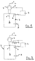
Die Figur 1 zeigt in der Prinzipdarstellung die Regelung eines Abluftvolumenstroms 1 aus einem Garraum 2 eines Backofens 3 durch ein Gebläse 4 an die Umgebung. Dabei wird die Drehzahl 5 in Abhängigkeit einer durch einen Gassensor 6 gemessenen Gaskonzentration im Garraum 2 des Backofens 3 gesteuert. Hierzu ist zwischen dem Gebläse 4 und dem Sensor 6 eine Elektronik 7 vorgesehen, die die Sensorsignale zur Drehzahlregelung verarbeitet. Dabei kann in den Garraum 2 aufgrund von Leckagestellen Zuluft 8 eintreten.1 shows in the schematic representation of the regulation of an exhaust air volume flow 1 from a
Die Elektronik 7 zur Veränderung des Abluftvolumenstroms 1 ist Stand der Technik und kann z. B. die Drehzahl des Gebläses 4 oder die Ansteuerung des Öffnungsquerschnittes einer Bypassklappe 9 an der Saugseite des Gebläses 4, wie dies in der Figur 2 dargestellt ist, regeln. Eine Zuluftöffnung 8 kann eine konstruktiv vorgesehene Öffnung sein, durch die trockene Küchenraumluft in den Garraum 2 nachgezogen werden kann, wenn aus dem Garraum 2 abgesaugt wird. Die Zuluftöffnung 8 kann aber auch eine oder mehrere Luftlecks 8 am Backofen 3 sein, die beinahe unvermeidlich immer da sind, z. B. Spalte im Tür- oder Lampendichtungsbereich oder an den Durchführungen für Heizkörper, Gargutthermometer oder dergleichen. Dies ist insbesondere in der Figur 3 dargestellt.The
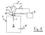
Eine andere Variante zeigt die Figur 4, bei der der Gassensor 6 insbesondere in der Abluftführung angeordnet ist.Another variant is shown in FIG. 4, in which the
Die Figur 5 unterscheidet sich gegenüber der Figur 4 nur dadurch, dass der Gassensor 6 in Strömungsrichtung hinter einem Abluftkatalysator 10 angeordnet ist, bzw. hinter einem beheizbaren Abluftkatalysator oder einem beheizten temperaturgeregelten Abluftkatalysator.FIG. 5 differs from FIG. 4 only in that the
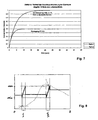
Bei dem erfindungsgemäßen Verfahren wird, dargestellt in Figur 8, in einem ersten Zeitintervall, wie dies beispielsweise in Figur 6 bei geringem Wrasenanfall dargestellt ist, die Gaskonzentration (gestrichelte Linie) und die Drehzahl (durchgezogene Linie) für das Gebläse 4 gemessen und in der elektrischen Steuerung 7 des Backofens 3 daraus die Gebläsedrehzahl für das darauf folgende zweite Zeitintervall automatisch ermittelt und festgelegt.In the method according to the invention, as shown in FIG. 8, the gas concentration (dashed line) and the rotational speed (solid line) for the fan 4 are measured in a first time interval, as shown, for example, in
In dem folgenden zweiten Zeitintervall wird die so ermittelte Drehzahl des Gebläses 4 im Wesentlichen konstant gehalten. Beide Zeitintervalle, einmal mit variierender Drehzahl bzw. mit konstanter Drehzahl, wiederholen sich alternierend während des Garvorganges, wobei die Dauer des zweiten Zeitintervalls größer als die des ersten Zeitintervalls ist. So zeigt die Figur 8 einen zeitlichen Verlauf der Wrasenabgabe über die Zeit aus dem Lebensmittel (gestrichelte Linie). Dabei ist diese etwa gleich dem zeitlichen Verlauf der Feuchteabgabe/Zeit oder dem zeitlichen Verlauf der (02-Abreicherung)/Zeit. Der zeitliche Verlauf der relevanten Gebläsedrehzahl in der Grafik ist mit einer durchgezogenen Linie dargestellt. Über die Zeitachse sind zwei Messzyklen I und II dargestellt, in denen die für das jeweils nachfolgende zweite Zeitintervall bis zum nächsten Messzyklus erforderliche Gebläsedrehzahl bestimmt wird.In the following second time interval, the thus determined speed of the fan 4 is kept substantially constant. Both time intervals, once with varying speed or at constant speed, repeat alternately during the cooking process, wherein the duration of the second time interval is greater than that of the first time interval. Thus, Figure 8 shows a time course of Wrasenabgabe over time from the food (dashed line). This is about the same time course of the moisture delivery / time or the time course of (02-depletion) / time. The time course of the relevant fan speed in the graph is shown by a solid line. Two measuring cycles I and II are shown over the time axis, in which the blower speed required for the respective subsequent second time interval until the next measuring cycle is determined.
Für das Funktionieren des Verfahrens wird unterstellt, dass in jedem Messzyklus zur Bestimmung der erforderlichen Gebläsedrehzahl die zeitliche Änderung der Wrasenabsaugung durch Änderung der Gebläsedrehzahl (sehr) groß ist, gegenüber der Änderung des pro Zeit aus dem Lebensmittel abgegebenen Wrasens oder der Änderung der pro Zeit in Abhängigkeit des erzeugten Wrasens abnehmenden Sauerstoffkonzentration. Das ist in der Regel erfüllt, weil Änderungsprozesse im Lebensmittel beim Garen typischerweise langsam vonstatten gehen, während eine Gebläsedrehzahl vergleichsweise schnell durch das erste Zeitintervall gefahren werden kann.For the operation of the method, it is assumed that in each measuring cycle for determining the required fan speed, the time change of the vapor suction by changing the fan speed is (very) large, compared to the change in the Wrasens released from the food per time or the change in the time in Dependence of the generated vapor on decreasing oxygen concentration. This is usually true because cooking change processes typically are slow during cooking, while a fan speed can be driven relatively quickly through the first time interval.
Vor Beginn eines Messintervalls, also eines ersten Zeitintervalls, wird nun (ein letztes Mal vor Verändern der Gebläsedrehzahl) eine Wrasenmenge/Zeit aus dem Lebensmittel gemessen. Jetzt wird, wie oben beschrieben, unterstellt, dass diese Wrasenmenge/Zeit aus dem Lebensmittel und damit die Gaskonzentration bei konstantem Abluftvolumenstrom über den Messzyklus in ausreichender Genauigkeit konstant bleibt. Die Gebläsedrehzahl (durchgezogene Linie) wird z.B. von min. nach max. gefahren. Die Gebläsedrehzahl, bei der die Wrasenkonzentration bzw. die Feuchtekonzentration erstmals unter den letzten Messwert abzufallen oder die Sauerstoffkonzentration erstmals über den letzten Messwert vor dem Messzyklus anzusteigen beginnt, ist eine Kenngröße für die erforderliche Gebläsedrehzahl, dargestellt in der Figur 8 im Messzyklus I durch die Projektionslinie. Um das erstmalige Abfallen oder Ansteigen sicher zu erkennen, ist es sinnvoll, etwas weiter über diesen Punkt zu fahren. Das geschieht i. d .R. automatisch beim Durchfahren des min.-max. Bereiches für die Gebläsedrehzahl bzw. des Abluftvolumenstroms.Before the start of a measurement interval, ie a first time interval, a quantity of vapor / time from the food is now measured (one last time before the fan speed is changed). Now, as described above, it is assumed that this quantity of fume / time from the food and thus the gas concentration at a constant exhaust air volume flow remains constant with sufficient accuracy over the measuring cycle. The fan speed (solid line) is e.g. from min. after max. hazards. The fan speed at which the vapor concentration or the moisture concentration first drops below the last measured value or the oxygen concentration begins to rise above the last measured value before the measuring cycle for the first time is a parameter for the required fan speed, shown in FIG. 8 in the measuring cycle I through the projection line , In order to recognize the first falling or rising safely, it makes sense to drive a little further on this point. This happens i. d .R. automatically when passing through the min.-max. Range for the fan speed and the exhaust air volume flow.
Die gewünschte Gebläsedrehzahl wird nun bezüglich der so gefundenen Absaugleistung nach dem Messzyklus I für eine Folgezeit so lange festgestellt, bis ein neuer Wert in einem weiteren Messzyklus, hier II, ermittelt wird.The desired blower speed is now determined with respect to the suction power found after the measuring cycle I for a follow-up time until a new value in a further measurement cycle, here II, is determined.
Die gewünschte Gebläsedrehzahl kann je nach Vorhaben genau in dem Punkt liegen, wo der Messwert der Wrasenabgabe/Zeit erstmals unter den Wert vor dem Messzyklus zu sinken beginnt (gewünschte Absaugdrehzahl = Kenngröße). Sie kann aber auch gewollt etwas höher (gewünschte Absaugdrehzahl > Kenngröße) oder niedriger (gewünschte Absaugdrehzahl < Kenngröße) liegen, z.B. um einen hinterlegten Prozentwert von der Kenngröße (z.B. + 10 % oder - 10 %).Depending on the project, the desired blower speed can be exactly at the point where the measured value of the vapor delivery / time first begins to drop below the value before the measuring cycle (desired extraction speed = parameter). But it can also be intentionally slightly higher (desired extraction speed> characteristic) or lower (desired extraction speed <characteristic), e.g. a stored percentage of the characteristic (for example + 10% or - 10%).
Aufgrund dieser Ausbildung wird insbesondere Rechenkapazität eingespart, weil nur in dem kürzeren ersten Zeitintervall, hier Messzyklus I und II, die Gaskonzentration gemessen wird.Due to this design, in particular computing capacity is saved, because only in the shorter first time interval, here measuring cycle I and II, the gas concentration is measured.
Dabei ist die Dauer des ersten Zeitintervalls derart kurz gewählt, dass die Gaskonzentration in dem Garraum 2 bei einem gleich bleibenden Abluftvolumenstrom während des ersten Zeitintervalls im Wesentlichen konstant bleibt. Die Drehzahl des Gebläses 4 wird während des ersten Zeitintervalls, ausgehend von einer niedrigen Drehzahl, niedriger Schwellenwert, bei der lediglich ein Teil des während des Garvorgangs entstehenden Wrasens durch das Gebläse 4 an die Umgebung abgegeben wird, kontinuierlich oder in Stufen automatisch erhöht, wie dies in der Figur 8 zu erkennen ist, bis der Gassensor 6 eine Gaskonzentration misst, die ungleich einer zu Beginn des ersten Zeitintervalls gemessenen Start-GasKonzentration ist. In Abhängigkeit der letzten Drehzahl wird die Drehzahl des Gebläses 4 für das zweite Zeitintervall automatisch festgelegt, und über das zweite Zeitintervall konstant gehalten. Ist das zweite Zeitintervall abgelaufen, beginnt die Messung wieder mit dem ersten Zeitintervall, in dem insbesondere die Gaskonzentration gemessen wird.In this case, the duration of the first time interval is selected to be so short that the gas concentration in the
Es versteht sich von selbst, dass, wenn als Gaskonzentration die Sauerstoffkonzentration in dem Garraum 2 durch den als Sauerstoffsensor ausgebildeten Gassensor 6 gemessen wird, sich der Kurvenverlauf entsprechend anders darstellt, weil mit zunehmender Garzeit die Sauerstoffkonzentration im Ofenraum 3 geringer wird. Das Sauerstoffsignal beginnt in dem Moment zu steigen, in dem aufgrund der Absaugung durch die Zuluftöffnungen 8 nicht länger Wrasen austritt, sondern Sauerstoff aus der Küchenumluft nachgezogen wird. Dann fängt auch wieder das erste Zeitintervall an, in dem insbesondere die Sauerstoffkonzentration gemessen wird. In vorteilhafter Weiterbildung wird die Gaskonzentration eines durch den Garvorgang erzeugten Gases in dem Garraum 2 durch den Gassensor 6 gemessen.It goes without saying that when the oxygen concentration in the
Beispiele für unterschiedliche Volumenstromverhältnisse aufgrund von Wrasenentstehung und Wrasenabsaugung und Zuluft sind in der Figur 6 dargestellt, wobei hier die Figuren 6a und 6b keine Verdünnung des Wrasens durch Zuluft 8 zeigt, und wobei in beiden Fällen die gleiche Wrasenkonzentration gemessen wird. Die Figur 6c zeigt hingegen eine Verdünnung des Wrasens durch Zuluft 8, so dass sich im Garraum 2 eine niedrigere Wrasenkonzentration bzw. Feuchtekonzentration bzw. eine höhere Sauerstoffkonzentration einstellt.Examples of different volume flow conditions due to vapor formation and vapor suction and supply air are shown in FIG. 6, wherein FIGS. 6a and 6b show no dilution of the vapor by
Die Figur 7 zeigt den zeitlichen Verlauf der Feuchteanreicherung im Ofenraum bei einer Absaugung von 10 l/min und bei 20 l/min.FIG. 7 shows the time course of the moisture accumulation in the furnace chamber with an extraction of 10 l / min and at 20 l / min.
Claims (3)
dadurch gekennzeichnet,
dass als Gaskonzentration die Sauerstoffkonzentration in dem Garraum (2) durch den als Sauerstoffsensor ausgebildeten Gassensor (6) gemessen wird.Method according to claim 1,
characterized,
in that the oxygen concentration in the cooking chamber (2) is measured as the gas concentration by the gas sensor (6) designed as an oxygen sensor.
dadurch gekennzeichnet,
dass als Gaskonzentration die Konzentration eines durch den Garvorgang erzeugten Gases in dem Garraum (2) durch den Gassensor (6) gemessen wird.Method according to claim 1,
characterized,
in that the concentration of a gas produced by the cooking process in the cooking chamber (2) is measured by the gas sensor (6) as gas concentration.
Priority Applications (1)
| Application Number | Priority Date | Filing Date | Title |
|---|---|---|---|
| PL07016042T PL1906096T3 (en) | 2006-09-14 | 2007-08-16 | Method for regulating the exhaust air volume flow from the cooking chamber of an oven |
Applications Claiming Priority (1)
| Application Number | Priority Date | Filing Date | Title |
|---|---|---|---|
| DE102006043933A DE102006043933A1 (en) | 2006-09-14 | 2006-09-14 | Method for controlling the exhaust air volume flow from a cooking chamber of a baking oven |
Publications (3)
| Publication Number | Publication Date |
|---|---|
| EP1906096A2 true EP1906096A2 (en) | 2008-04-02 |
| EP1906096A3 EP1906096A3 (en) | 2011-04-06 |
| EP1906096B1 EP1906096B1 (en) | 2014-06-18 |
Family
ID=38640110
Family Applications (1)
| Application Number | Title | Priority Date | Filing Date |
|---|---|---|---|
| EP07016042.9A Not-in-force EP1906096B1 (en) | 2006-09-14 | 2007-08-16 | Method for regulating the exhaust air volume flow from the cooking chamber of an oven |
Country Status (5)
| Country | Link |
|---|---|
| US (1) | US7997263B2 (en) |
| EP (1) | EP1906096B1 (en) |
| DE (1) | DE102006043933A1 (en) |
| ES (1) | ES2480197T3 (en) |
| PL (1) | PL1906096T3 (en) |
Cited By (2)
| Publication number | Priority date | Publication date | Assignee | Title |
|---|---|---|---|---|
| EP2615375A1 (en) * | 2012-01-11 | 2013-07-17 | BSH Bosch und Siemens Hausgeräte GmbH | Cooking device with sensor for the cooking chamber |
| CN114052462A (en) * | 2020-07-31 | 2022-02-18 | 佛山市顺德区美的电热电器制造有限公司 | Cooking appliance, control method, control device, and computer-readable storage medium |
Families Citing this family (10)
| Publication number | Priority date | Publication date | Assignee | Title |
|---|---|---|---|---|
| DE102006044039B3 (en) * | 2006-09-14 | 2007-12-27 | Miele & Cie. Kg | Baking oven`s cooking area air volume flow controlling method, involves selecting period of one of time intervals as short interval, where temperature difference between temperatures remains constant with same and stable air volume flow |
| DE102008036683B4 (en) * | 2008-08-06 | 2013-12-24 | Rational Ag | Cooking appliance and method for controlling a cooking process |
| EP2516932B1 (en) * | 2009-12-22 | 2016-07-13 | Arçelik Anonim Sirketi | Method for operating an oven comprising odor sensor |
| US10119708B2 (en) * | 2013-04-23 | 2018-11-06 | Alto-Shaam, Inc. | Oven with automatic open/closed system mode control |
| DE102016215650A1 (en) * | 2016-08-19 | 2018-02-22 | BSH Hausgeräte GmbH | Haushaltsgargerät |
| US20180228169A1 (en) * | 2017-02-14 | 2018-08-16 | Haier Us Appliance Solutions, Inc. | Method for operating an indoor pizza oven appliance |
| CN110542139A (en) * | 2019-09-30 | 2019-12-06 | 佛山市顺德区美的洗涤电器制造有限公司 | Control method of range hood and range hood |
| CN111998415A (en) * | 2020-09-11 | 2020-11-27 | 华帝股份有限公司 | Cooking equipment and oil smoke emission control method |
| CN112426025B (en) * | 2020-10-21 | 2022-04-05 | 华帝股份有限公司 | Exhaust control method of cooking equipment after cooking is finished and cooking equipment |
| KR20220153892A (en) | 2021-05-12 | 2022-11-21 | 엘지전자 주식회사 | Cooking appliance and method for controlling the same |
Citations (6)
| Publication number | Priority date | Publication date | Assignee | Title |
|---|---|---|---|---|
| DE3804678A1 (en) * | 1988-02-15 | 1989-08-24 | Buderus Kuechentechnik | Method for operating a baking oven with microwaves and electrical resistance heating |
| EP1156282A1 (en) * | 2000-05-17 | 2001-11-21 | V-Zug AG | Cooking oven with venting system |
| DE10211522A1 (en) * | 2002-03-15 | 2003-09-25 | Bsh Bosch Siemens Hausgeraete | Oven, especially with a mechanism for pyrolytic self-cleaning comprises a controllable flap for controlling the airflow into oven |
| US20040144768A1 (en) * | 2003-01-27 | 2004-07-29 | General Electric Company | Carbon monoxide sensed oven cleaning apparatus and method |
| US6920874B1 (en) * | 2004-03-01 | 2005-07-26 | Robert Paul Siegel | Intelligent ventilating safety range hood |
| DE102004049927A1 (en) * | 2004-10-14 | 2006-04-27 | Miele & Cie. Kg | Method for controlling a cooking process in a cooking appliance |
Family Cites Families (7)
| Publication number | Priority date | Publication date | Assignee | Title |
|---|---|---|---|---|
| US3625135A (en) * | 1970-04-22 | 1971-12-07 | Honeywell Inc | Automatically controlled cooking area ventilating system |
| DE2925947A1 (en) * | 1979-06-27 | 1981-01-22 | Siemens Ag | Magnetic tape recording head heater - has power transistor used as both temp. sensor and heating element |
| US4954694A (en) * | 1989-01-31 | 1990-09-04 | Matsushita Electric Industrial Co., Ltd. | Cooking oven having function to automatically clean soils attached to inner walls thereof |
| JP2002190686A (en) * | 2000-12-22 | 2002-07-05 | Toshiba Corp | Cooling device for electronic equipment |
| US6462319B1 (en) * | 2001-05-29 | 2002-10-08 | Bsh Home Appliances Corporation | Multi-stage self-cleaning control for oven |
| US20040129800A1 (en) * | 2002-10-24 | 2004-07-08 | Valois S.A.S. | Fluid dispenser |
| AU2003203444B2 (en) * | 2002-10-25 | 2005-01-06 | Fisher & Paykel Appliances Limited | Cooking Appliance Venting System |
-
2006
- 2006-09-14 DE DE102006043933A patent/DE102006043933A1/en not_active Ceased
-
2007
- 2007-08-16 EP EP07016042.9A patent/EP1906096B1/en not_active Not-in-force
- 2007-08-16 PL PL07016042T patent/PL1906096T3/en unknown
- 2007-08-16 ES ES07016042.9T patent/ES2480197T3/en active Active
- 2007-09-07 US US11/851,474 patent/US7997263B2/en not_active Expired - Fee Related
Patent Citations (6)
| Publication number | Priority date | Publication date | Assignee | Title |
|---|---|---|---|---|
| DE3804678A1 (en) * | 1988-02-15 | 1989-08-24 | Buderus Kuechentechnik | Method for operating a baking oven with microwaves and electrical resistance heating |
| EP1156282A1 (en) * | 2000-05-17 | 2001-11-21 | V-Zug AG | Cooking oven with venting system |
| DE10211522A1 (en) * | 2002-03-15 | 2003-09-25 | Bsh Bosch Siemens Hausgeraete | Oven, especially with a mechanism for pyrolytic self-cleaning comprises a controllable flap for controlling the airflow into oven |
| US20040144768A1 (en) * | 2003-01-27 | 2004-07-29 | General Electric Company | Carbon monoxide sensed oven cleaning apparatus and method |
| US6920874B1 (en) * | 2004-03-01 | 2005-07-26 | Robert Paul Siegel | Intelligent ventilating safety range hood |
| DE102004049927A1 (en) * | 2004-10-14 | 2006-04-27 | Miele & Cie. Kg | Method for controlling a cooking process in a cooking appliance |
Cited By (2)
| Publication number | Priority date | Publication date | Assignee | Title |
|---|---|---|---|---|
| EP2615375A1 (en) * | 2012-01-11 | 2013-07-17 | BSH Bosch und Siemens Hausgeräte GmbH | Cooking device with sensor for the cooking chamber |
| CN114052462A (en) * | 2020-07-31 | 2022-02-18 | 佛山市顺德区美的电热电器制造有限公司 | Cooking appliance, control method, control device, and computer-readable storage medium |
Also Published As
| Publication number | Publication date |
|---|---|
| DE102006043933A1 (en) | 2008-04-03 |
| PL1906096T3 (en) | 2014-10-31 |
| EP1906096B1 (en) | 2014-06-18 |
| EP1906096A3 (en) | 2011-04-06 |
| US7997263B2 (en) | 2011-08-16 |
| US20080066732A1 (en) | 2008-03-20 |
| ES2480197T3 (en) | 2014-07-25 |
Similar Documents
| Publication | Publication Date | Title |
|---|---|---|
| EP1906096B1 (en) | Method for regulating the exhaust air volume flow from the cooking chamber of an oven | |
| DE102006044039B3 (en) | Baking oven`s cooking area air volume flow controlling method, involves selecting period of one of time intervals as short interval, where temperature difference between temperatures remains constant with same and stable air volume flow | |
| EP2469173B1 (en) | Method for controlling a cooking process in a cooking device and cooking device | |
| EP3390916B1 (en) | Method for operating a commercial cooking device and such a cooking device | |
| EP2775215B1 (en) | Baking oven with temperature limitation depending on the climate in the oven | |
| EP1619443B1 (en) | Oven with controllable ventilation | |
| EP3437476B1 (en) | Cooking device and method for using a cooking device | |
| EP1489361A2 (en) | Method for non-contact controlling of a cooking process in a cooking appliance and cooking appliance | |
| EP2154435A2 (en) | Cooking device and method for monitoring a cooking process | |
| EP1156282B1 (en) | Cooking oven with venting system | |
| DE102008012395A1 (en) | Oven with air outlet | |
| EP3437477B1 (en) | Cooking device and method for operating a cooking device | |
| EP1855058A1 (en) | Process and apparatus to cook dishes with vapour | |
| EP2510826A1 (en) | Manually operated dryer | |
| EP0845234B2 (en) | Device and method to control the amount of humidity in a cooking device | |
| DE60202550T2 (en) | Extractor hood and control system for a trigger system | |
| DE10327864B4 (en) | Method for the contactless control of a cooking process in a cooking appliance and cooking appliance | |
| DE102017128743B3 (en) | Method for influencing a cooking process | |
| DE102018207615B4 (en) | Method for operating a household microwave device and household microwave device for carrying out the method | |
| DE102005035564A1 (en) | Household baking-oven controlling method involves collecting and evaluating air humidity in baking muffle as baking-or-cooking parameter during cooking process, and adjusting air humidity by influence of air removal or air supply of muffle | |
| EP2445311A2 (en) | Combination cooking device | |
| EP2860458A1 (en) | Method for operating a cooking appliance in the form of a combi-steamer and cooking appliance for carrying out the said method | |
| EP2220970B2 (en) | Refining preparation with detection of a cooling rate | |
| DE10129885C1 (en) | Process for regulating the heating power of a baking oven used in bakeries comprises integrating the difference between the theoretical temperature and the actual temperature over the baking time; and correcting the theoretical temperature | |
| DE3731318C2 (en) |
Legal Events
| Date | Code | Title | Description |
|---|---|---|---|
| PUAI | Public reference made under article 153(3) epc to a published international application that has entered the european phase |
Free format text: ORIGINAL CODE: 0009012 |
|
| AK | Designated contracting states |
Kind code of ref document: A2 Designated state(s): AT BE BG CH CY CZ DE DK EE ES FI FR GB GR HU IE IS IT LI LT LU LV MC MT NL PL PT RO SE SI SK TR |
|
| AX | Request for extension of the european patent |
Extension state: AL BA HR MK YU |
|
| REG | Reference to a national code |
Ref country code: DE Ref legal event code: R079 Ref document number: 502007013198 Country of ref document: DE Free format text: PREVIOUS MAIN CLASS: F24C0015000000 Ipc: F24C0015200000 |
|
| PUAL | Search report despatched |
Free format text: ORIGINAL CODE: 0009013 |
|
| AK | Designated contracting states |
Kind code of ref document: A3 Designated state(s): AT BE BG CH CY CZ DE DK EE ES FI FR GB GR HU IE IS IT LI LT LU LV MC MT NL PL PT RO SE SI SK TR |
|
| AX | Request for extension of the european patent |
Extension state: AL BA HR MK RS |
|
| RIC1 | Information provided on ipc code assigned before grant |
Ipc: F24C 15/20 20060101AFI20110225BHEP Ipc: F24C 7/08 20060101ALI20110225BHEP |
|
| 17P | Request for examination filed |
Effective date: 20110510 |
|
| AKX | Designation fees paid |
Designated state(s): AT BE BG CH CY CZ DE DK EE ES FI FR GB GR HU IE IS IT LI LT LU LV MC MT NL PL PT RO SE SI SK TR |
|
| GRAP | Despatch of communication of intention to grant a patent |
Free format text: ORIGINAL CODE: EPIDOSNIGR1 |
|
| INTG | Intention to grant announced |
Effective date: 20140205 |
|
| GRAS | Grant fee paid |
Free format text: ORIGINAL CODE: EPIDOSNIGR3 |
|
| GRAA | (expected) grant |
Free format text: ORIGINAL CODE: 0009210 |
|
| AK | Designated contracting states |
Kind code of ref document: B1 Designated state(s): AT BE BG CH CY CZ DE DK EE ES FI FR GB GR HU IE IS IT LI LT LU LV MC MT NL PL PT RO SE SI SK TR |
|
| REG | Reference to a national code |
Ref country code: GB Ref legal event code: FG4D Free format text: NOT ENGLISH |
|
| REG | Reference to a national code |
Ref country code: CH Ref legal event code: EP |
|
| REG | Reference to a national code |
Ref country code: ES Ref legal event code: GC2A Effective date: 20140709 Ref country code: AT Ref legal event code: REF Ref document number: 673567 Country of ref document: AT Kind code of ref document: T Effective date: 20140715 |
|
| REG | Reference to a national code |
Ref country code: IE Ref legal event code: FG4D Free format text: LANGUAGE OF EP DOCUMENT: GERMAN |
|
| REG | Reference to a national code |
Ref country code: ES Ref legal event code: FG2A Ref document number: 2480197 Country of ref document: ES Kind code of ref document: T3 Effective date: 20140725 |
|
| REG | Reference to a national code |
Ref country code: DE Ref legal event code: R096 Ref document number: 502007013198 Country of ref document: DE Effective date: 20140731 |
|
| REG | Reference to a national code |
Ref country code: DE Ref legal event code: R084 Ref document number: 502007013198 Country of ref document: DE Effective date: 20140628 |
|
| PG25 | Lapsed in a contracting state [announced via postgrant information from national office to epo] |
Ref country code: LT Free format text: LAPSE BECAUSE OF FAILURE TO SUBMIT A TRANSLATION OF THE DESCRIPTION OR TO PAY THE FEE WITHIN THE PRESCRIBED TIME-LIMIT Effective date: 20140618 Ref country code: GR Free format text: LAPSE BECAUSE OF FAILURE TO SUBMIT A TRANSLATION OF THE DESCRIPTION OR TO PAY THE FEE WITHIN THE PRESCRIBED TIME-LIMIT Effective date: 20140919 Ref country code: FI Free format text: LAPSE BECAUSE OF FAILURE TO SUBMIT A TRANSLATION OF THE DESCRIPTION OR TO PAY THE FEE WITHIN THE PRESCRIBED TIME-LIMIT Effective date: 20140618 Ref country code: CY Free format text: LAPSE BECAUSE OF FAILURE TO SUBMIT A TRANSLATION OF THE DESCRIPTION OR TO PAY THE FEE WITHIN THE PRESCRIBED TIME-LIMIT Effective date: 20140618 |
|
| REG | Reference to a national code |
Ref country code: PL Ref legal event code: T3 Ref country code: PL Ref legal event code: LICE Effective date: 20140806 |
|
| REG | Reference to a national code |
Ref country code: NL Ref legal event code: VDEP Effective date: 20140618 |
|
| REG | Reference to a national code |
Ref country code: LT Ref legal event code: MG4D |
|
| PG25 | Lapsed in a contracting state [announced via postgrant information from national office to epo] |
Ref country code: SE Free format text: LAPSE BECAUSE OF FAILURE TO SUBMIT A TRANSLATION OF THE DESCRIPTION OR TO PAY THE FEE WITHIN THE PRESCRIBED TIME-LIMIT Effective date: 20140618 Ref country code: LV Free format text: LAPSE BECAUSE OF FAILURE TO SUBMIT A TRANSLATION OF THE DESCRIPTION OR TO PAY THE FEE WITHIN THE PRESCRIBED TIME-LIMIT Effective date: 20140618 |
|
| PG25 | Lapsed in a contracting state [announced via postgrant information from national office to epo] |
Ref country code: CZ Free format text: LAPSE BECAUSE OF FAILURE TO SUBMIT A TRANSLATION OF THE DESCRIPTION OR TO PAY THE FEE WITHIN THE PRESCRIBED TIME-LIMIT Effective date: 20140618 Ref country code: EE Free format text: LAPSE BECAUSE OF FAILURE TO SUBMIT A TRANSLATION OF THE DESCRIPTION OR TO PAY THE FEE WITHIN THE PRESCRIBED TIME-LIMIT Effective date: 20140618 Ref country code: RO Free format text: LAPSE BECAUSE OF FAILURE TO SUBMIT A TRANSLATION OF THE DESCRIPTION OR TO PAY THE FEE WITHIN THE PRESCRIBED TIME-LIMIT Effective date: 20140618 Ref country code: SK Free format text: LAPSE BECAUSE OF FAILURE TO SUBMIT A TRANSLATION OF THE DESCRIPTION OR TO PAY THE FEE WITHIN THE PRESCRIBED TIME-LIMIT Effective date: 20140618 Ref country code: PT Free format text: LAPSE BECAUSE OF FAILURE TO SUBMIT A TRANSLATION OF THE DESCRIPTION OR TO PAY THE FEE WITHIN THE PRESCRIBED TIME-LIMIT Effective date: 20141020 |
|
| PG25 | Lapsed in a contracting state [announced via postgrant information from national office to epo] |
Ref country code: NL Free format text: LAPSE BECAUSE OF FAILURE TO SUBMIT A TRANSLATION OF THE DESCRIPTION OR TO PAY THE FEE WITHIN THE PRESCRIBED TIME-LIMIT Effective date: 20140618 Ref country code: IS Free format text: LAPSE BECAUSE OF FAILURE TO SUBMIT A TRANSLATION OF THE DESCRIPTION OR TO PAY THE FEE WITHIN THE PRESCRIBED TIME-LIMIT Effective date: 20141018 |
|
| REG | Reference to a national code |
Ref country code: DE Ref legal event code: R097 Ref document number: 502007013198 Country of ref document: DE |
|
| PG25 | Lapsed in a contracting state [announced via postgrant information from national office to epo] |
Ref country code: MC Free format text: LAPSE BECAUSE OF FAILURE TO SUBMIT A TRANSLATION OF THE DESCRIPTION OR TO PAY THE FEE WITHIN THE PRESCRIBED TIME-LIMIT Effective date: 20140618 Ref country code: LU Free format text: LAPSE BECAUSE OF FAILURE TO SUBMIT A TRANSLATION OF THE DESCRIPTION OR TO PAY THE FEE WITHIN THE PRESCRIBED TIME-LIMIT Effective date: 20140816 |
|
| REG | Reference to a national code |
Ref country code: CH Ref legal event code: PL |
|
| PLBE | No opposition filed within time limit |
Free format text: ORIGINAL CODE: 0009261 |
|
| STAA | Information on the status of an ep patent application or granted ep patent |
Free format text: STATUS: NO OPPOSITION FILED WITHIN TIME LIMIT |
|
| PG25 | Lapsed in a contracting state [announced via postgrant information from national office to epo] |
Ref country code: CH Free format text: LAPSE BECAUSE OF NON-PAYMENT OF DUE FEES Effective date: 20140831 Ref country code: DK Free format text: LAPSE BECAUSE OF FAILURE TO SUBMIT A TRANSLATION OF THE DESCRIPTION OR TO PAY THE FEE WITHIN THE PRESCRIBED TIME-LIMIT Effective date: 20140618 Ref country code: LI Free format text: LAPSE BECAUSE OF NON-PAYMENT OF DUE FEES Effective date: 20140831 Ref country code: BE Free format text: LAPSE BECAUSE OF NON-PAYMENT OF DUE FEES Effective date: 20140831 |
|
| REG | Reference to a national code |
Ref country code: IE Ref legal event code: MM4A |
|
| 26N | No opposition filed |
Effective date: 20150319 |
|
| GBPC | Gb: european patent ceased through non-payment of renewal fee |
Effective date: 20140918 |
|
| REG | Reference to a national code |
Ref country code: FR Ref legal event code: ST Effective date: 20150430 |
|
| PG25 | Lapsed in a contracting state [announced via postgrant information from national office to epo] |
Ref country code: GB Free format text: LAPSE BECAUSE OF NON-PAYMENT OF DUE FEES Effective date: 20140918 Ref country code: SI Free format text: LAPSE BECAUSE OF FAILURE TO SUBMIT A TRANSLATION OF THE DESCRIPTION OR TO PAY THE FEE WITHIN THE PRESCRIBED TIME-LIMIT Effective date: 20140618 |
|
| PG25 | Lapsed in a contracting state [announced via postgrant information from national office to epo] |
Ref country code: FR Free format text: LAPSE BECAUSE OF NON-PAYMENT OF DUE FEES Effective date: 20140901 Ref country code: IE Free format text: LAPSE BECAUSE OF NON-PAYMENT OF DUE FEES Effective date: 20140816 |
|
| REG | Reference to a national code |
Ref country code: AT Ref legal event code: MM01 Ref document number: 673567 Country of ref document: AT Kind code of ref document: T Effective date: 20140816 |
|
| PG25 | Lapsed in a contracting state [announced via postgrant information from national office to epo] |
Ref country code: AT Free format text: LAPSE BECAUSE OF NON-PAYMENT OF DUE FEES Effective date: 20140816 |
|
| PG25 | Lapsed in a contracting state [announced via postgrant information from national office to epo] |
Ref country code: BG Free format text: LAPSE BECAUSE OF FAILURE TO SUBMIT A TRANSLATION OF THE DESCRIPTION OR TO PAY THE FEE WITHIN THE PRESCRIBED TIME-LIMIT Effective date: 20140618 |
|
| PG25 | Lapsed in a contracting state [announced via postgrant information from national office to epo] |
Ref country code: MT Free format text: LAPSE BECAUSE OF FAILURE TO SUBMIT A TRANSLATION OF THE DESCRIPTION OR TO PAY THE FEE WITHIN THE PRESCRIBED TIME-LIMIT Effective date: 20140618 |
|
| PG25 | Lapsed in a contracting state [announced via postgrant information from national office to epo] |
Ref country code: HU Free format text: LAPSE BECAUSE OF FAILURE TO SUBMIT A TRANSLATION OF THE DESCRIPTION OR TO PAY THE FEE WITHIN THE PRESCRIBED TIME-LIMIT; INVALID AB INITIO Effective date: 20070816 |
|
| PGFP | Annual fee paid to national office [announced via postgrant information from national office to epo] |
Ref country code: IT Payment date: 20180823 Year of fee payment: 12 Ref country code: ES Payment date: 20180927 Year of fee payment: 12 Ref country code: DE Payment date: 20180831 Year of fee payment: 12 |
|
| PGFP | Annual fee paid to national office [announced via postgrant information from national office to epo] |
Ref country code: TR Payment date: 20180807 Year of fee payment: 12 |
|
| PGFP | Annual fee paid to national office [announced via postgrant information from national office to epo] |
Ref country code: PL Payment date: 20190702 Year of fee payment: 13 |
|
| REG | Reference to a national code |
Ref country code: DE Ref legal event code: R119 Ref document number: 502007013198 Country of ref document: DE |
|
| PG25 | Lapsed in a contracting state [announced via postgrant information from national office to epo] |
Ref country code: DE Free format text: LAPSE BECAUSE OF NON-PAYMENT OF DUE FEES Effective date: 20200303 |
|
| PG25 | Lapsed in a contracting state [announced via postgrant information from national office to epo] |
Ref country code: IT Free format text: LAPSE BECAUSE OF NON-PAYMENT OF DUE FEES Effective date: 20190816 |
|
| REG | Reference to a national code |
Ref country code: ES Ref legal event code: FD2A Effective date: 20210107 |
|
| PG25 | Lapsed in a contracting state [announced via postgrant information from national office to epo] |
Ref country code: ES Free format text: LAPSE BECAUSE OF NON-PAYMENT OF DUE FEES Effective date: 20190817 |
|
| PG25 | Lapsed in a contracting state [announced via postgrant information from national office to epo] |
Ref country code: TR Free format text: LAPSE BECAUSE OF NON-PAYMENT OF DUE FEES Effective date: 20190816 |
|
| PG25 | Lapsed in a contracting state [announced via postgrant information from national office to epo] |
Ref country code: PL Free format text: LAPSE BECAUSE OF NON-PAYMENT OF DUE FEES Effective date: 20200816 |