EP1906648A2 - Image forming system - Google Patents
Image forming system Download PDFInfo
- Publication number
- EP1906648A2 EP1906648A2 EP07253812A EP07253812A EP1906648A2 EP 1906648 A2 EP1906648 A2 EP 1906648A2 EP 07253812 A EP07253812 A EP 07253812A EP 07253812 A EP07253812 A EP 07253812A EP 1906648 A2 EP1906648 A2 EP 1906648A2
- Authority
- EP
- European Patent Office
- Prior art keywords
- image data
- color adjustment
- adjustment parameters
- information image
- main image
- Prior art date
- Legal status (The legal status is an assumption and is not a legal conclusion. Google has not performed a legal analysis and makes no representation as to the accuracy of the status listed.)
- Withdrawn
Links
Images


Classifications
-
- H—ELECTRICITY
- H04—ELECTRIC COMMUNICATION TECHNIQUE
- H04N—PICTORIAL COMMUNICATION, e.g. TELEVISION
- H04N1/00—Scanning, transmission or reproduction of documents or the like, e.g. facsimile transmission; Details thereof
- H04N1/46—Colour picture communication systems
- H04N1/56—Processing of colour picture signals
- H04N1/60—Colour correction or control
- H04N1/6011—Colour correction or control with simulation on a subsidiary picture reproducer
-
- H—ELECTRICITY
- H04—ELECTRIC COMMUNICATION TECHNIQUE
- H04N—PICTORIAL COMMUNICATION, e.g. TELEVISION
- H04N1/00—Scanning, transmission or reproduction of documents or the like, e.g. facsimile transmission; Details thereof
- H04N1/46—Colour picture communication systems
- H04N1/56—Processing of colour picture signals
- H04N1/60—Colour correction or control
- H04N1/603—Colour correction or control controlled by characteristics of the picture signal generator or the picture reproducer
Definitions
- an image forming device such as a color printer is configured to express various colors by using a plurality of kinds of ink or toner of various colors which are different from each other (hereinafter, referred to as "color component") and change a rate of blending these color components.
- the print data is transmitted to the printer 20 through the printer port I/F 17, and the process is terminated.
- the printer 20 which has received the print data executes printing operation according to the received print data. With this printing operation, an image which is the main image associated with the information image is obtained when the color adjustment parameters are changed as shown in Fig. 6B. When the color adjustment parameters have not been changed, an image consists of the main image is obtained as shown in Fig. 6A.
- the only differences with respect to the first embodiment are: configuration of color adjustment parameters stored in the HDD 14; configuration of editing screen which is displayed in the color adjustment parameter editing process S120; data format of the information image data which is composed with the main image data in the print process S230; and contents of color transformation process which is executed in the print process S250. Therefore, the same configurations as in the first embodiment are given the same symbols/step numbers, and only the different portions will be explained.
- the editing screen 30A is configured such that the user can set up color adjustment parameters separately for characters and for images.
- the image forming system 1 enables the user to set the color adjustment parameters for characters and color adjustment parameters for images separately Therefore, it is possible to make color adjustment in more detailed manner within the same image.
- Fig. 9 is a flowchart showing the print process according to the third embodiment.
- step S210 in the first embodiment has been changed to a step S215
- step S230 in the first embodiment has been changed to steps S231 to S233.
- Other steps of the print process are similar to the process in the first embodiment.
- configuration of editing screen displayed in color adjustment parameter editing process S120, and parts of color adjustment parameter editing process and print process are different from those of the first embodiment. Therefore, the same configurations in the first embodiment are given the same symbols/step numbers without further explanation, and the different portions are mainly explained. It should be noted that there is a case where a print quality is preferably determined based on a plurality of print images which are printed based on a plurality of pieces of different main image data.
- the fourth embodiment is configured such that the information image is printed repeatedly.
- Fig. 11 is an illustration showing a configuration of the editing screen 30B according to the fourth embodiment.
- the editing screen 30B is configured similar to the editing screen 30 except that a text box 39 to set the number of printing the information image together with the main image (hereinafter, referred to as a "parameter print count") is added when the color adjustment parameters are changed.
- a text box 39 to set the number of printing the information image together with the main image (hereinafter, referred to as a "parameter print count") is added when the color adjustment parameters are changed.
- the color adjustment parameter editing process according to the fourth embodiment is different compared to the color adjustment parameter editing process according to the first embodiment in that steps S 143, S 145 have been newly added, steps S 180, S 190 have been changed to a step S191, and editing screen 30B is displayed in process S 120.
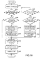
- Fig. 13 is a flowchart showing a print process according to the fourth embodiment.
- the parameter print count is equal to or less than 0, the information image will not be inserted to the main image, and the process goes to S250 without doing any operation. Namely, when the color adjustment parameters have been changed, the information image is inserted into the main image repeatedly, by the time indicated by the parameter print count. Thus, the indications of color adjustment parameters are printed over the main image.
- a configuration of color adjustment parameters stored in the HDD 14 a configuration of editing screen displayed in color adjustment parameter editing process, a color adjustment parameter editing process, and a print process are different from corresponding configurations of the first embodiment.
- the HDD 14 has areas to store the current setting values of each application ("WORD PROCESSOR”, “DRAWING”, “OTHERS"), and areas, which are commonly used, to store initial values (i.e., initial values before setting) of the application for which the adjustment parameters are being set.
- the HDD 14 has also areas storing the change flags for respective applications.
- the editing screen 30C is configured similarly to the editing screen 30 in the first embodiment except that a text box 34 to indicate an application of which color adjustment parameters to be changed is added.
- Fig. 15 is a flowchart which shows the color adjustment parameter editing process according to the fifth embodiment.
- the predetermined application may be any application setup preliminarily, or may be an application which was indicated when the enter button 35 was clicked in a previous setting operation.
- the process judges whether an operation to switch an application is executed using the text box 34.
- the process goes to S340, the current setting values of the color adjustment parameters are copied to the initial value area, the current setting values are reflected to the editing screen 30C, and the process returns to S330.
- the process judges whether the enter button 35 is clicked. If the enter button 35 is clicked, the process goes to S390, contents of the editing screen 30C are reflected to the current setting values of the color adjustment parameters of the application which is indicated in the text box 34 (hereinafter, referred to "selected application").
- the process judges whether the current setting values are equal to the initial values set in S310 or S340. If the current setting values are equal to the initial values, since the color adjustment parameters have not been changed, the process is terminated without doing any operation.
- the print processed-application list is a list indicating the applications with which printing operations have been executed with the color adjustment parameters being used.
- Fig. 17 shows an example of the print processed-application list.
- Fig. 16 is a flowchart showing the print process according to the fifth embodiment.
- the print process When the print process is activated, in S510, the image data from which the print data (i.e., the main image data) is generated is generated. Next, in S520, the process judges whether there exist the color adjustment parameters of an application which has issued a print instruction (hereinafter, referred to "requiring application"). If there exists such an application, the process goes to S530.
- requiring application the color adjustment parameters of an application which has issued a print instruction
- the image data (information image data) to be printed with characters in accordance with the preliminarily setup color is generated according to the contents of current setting values of color adjustment parameters related to the requiring application.
- the image data is then combined with the main image data generated in previous S510.
- the change flag related to the color adjustment parameters of the requesting application is reset (released), and the process goes to S600.
- S570 it is determined whether the requiring application is included in the print processed-application list. If the application is included in the list, since it is not necessary for the information image to be inserted to the main image, the process goes to S600. If the application is not included, since it is necessary for the information image to be inserted to the main image, the process goes to S580.
- the information image data to be printed with characters having a preliminarily set color is generated according to the current setting values of color adjustment parameters for the application categorized in "OTHERS.” Then, the information image data is combined with the main image data generated in S510.
- the requesting application is added to the print processed-application list, the change flag related to color adjustment parameters the application categorized in "OTHERS" are reset, and the process goes to S600.
- the color transformation is executed according to the current setting values of the color adjustment parameters corresponding to the requiring application (S600). Then, the color-transformed image data is transformed into the print data (S610). The print data is then transmitted to the printer 20 via the printer port I/F 17 (S620), and the process is terminated.
- the color adjustment parameters can be set for each kind of applications. Therefore, it is possible to adjust image quality according to characteristics of each application.
- a type of "OTHERS" is included in a categorization of applications. It may be modified such that a new categorization can be registered when there is no appropriate category is included in the selectable candidates.
- the information image is printed on the same side of the printing sheet where the main image is printed. If the printer 20 can print both sides of the printing sheet and the main image is printed only one side thereof, the information image may be printed on the other side of the sheet.
- Fig. 18 shows an example of such a modification. That is, Fig. 18 is a modified print process which is a modification of the print process shown in Fig. 5. In Fig. 18 and description below, the steps that are the same as those of Fig. 5 are assigned to the same step number used in Fig. 5 and description thereof is omitted for brevity.
Landscapes
- Engineering & Computer Science (AREA)
- Multimedia (AREA)
- Signal Processing (AREA)
- Facsimile Image Signal Circuits (AREA)
- Color, Gradation (AREA)
- Image Processing (AREA)
- Editing Of Facsimile Originals (AREA)
- Color Image Communication Systems (AREA)
- Record Information Processing For Printing (AREA)
Abstract
Description
- The present invention relates to an image forming system which forms an image corresponding to an image data on a printing sheet, and specifically to an image forming system which can change a color tone arbitrarily by manipulating color adjustment parameters.
- Conventionally, an image forming device such as a color printer is configured to express various colors by using a plurality of kinds of ink or toner of various colors which are different from each other (hereinafter, referred to as "color component") and change a rate of blending these color components.
- However, since printed colors are affected by various factors, even if a rate of blending color components is constant, the printed colors are not necessarily constant. In addition, a favorite of color varies depending on individuals. Therefore, the image forming device is generally provided with a color adjustment function.
- The color adjustment function is a function to increase or reduce the blend rate of specific color components more than or less than a preliminarily setup rate so as to print in a color tone a user desires. Generally, such a change is made by adjusting color adjustment parameters representing amount of color components.
- There is known an image forming device which can print typical test patterns including a numerical representation which shows setup color adjustment parameters (such as concentration) in numerical values and images corresponding to setup color adjustment parameters (such as a gray scale) in order to allow a user to recognize the change of a color tone of printed image according to changed color adjustment parameters. An example of such a technique is disclosed in
Japanese Patent Provisional Publication No. HEI 7-87318 - However, a color adjustment is a matter of sense, and it is difficult to imagine how the actual color tone would be from printed results of typical test patterns. Therefore, it is necessary to print actual image data instead of or in addition to test patterns (hereinafter, referred to as "test printing").
- That is, while varying setup of color adjustment parameters, test printings are executed with changing the parameters, and results are compared. Then, the color adjustment parameters are finally adopted as those at the time when the desirable color tones is obtained.
- When such a test printing is performed, whenever setup of color adjustment parameters is changed, it is necessary to write down or print the test patterns for later reference. Namely, every time when the setup is changed, the test patterns and actual image data are repeatedly printed as test printing (or write down contents of color adjustment parameters). Therefore, there has been a problem where troublesome work is required.
- The invention is advantageous in that an improved image forming system is provided with which system the color adjustment operation can be performed relatively easily.
- According to aspects of the invention, there is provided an image forming system which is configured such that a user is allowed to set color adjustment parameters, and information image data representing the contents of the color adjustment parameters set by the user is generated. Then, the information image data is combined with main image data to generate combined image data. An image is printed based on the combined image data with the color being adjusted in accordance with the color adjustment parameters set by the setting unit.
- According to the above configuration, printing of a color-adjusted image and printing of the color adjustment parameters can be executed simultaneously. Thus, a conventional test patterns are not necessarily printed.
- Optionally, the color adjustment parameters may be set for each of types of applications used for generating the main image data.
- Still optionally, the color adjustment parameters may be set for each of attributes of the main image data.
- Further, the information image may show contents of the color adjustment parameters for each of the attributes.
- Optionally, the combining unit may combine the information image data to the main image data such that the information image as printed has a predetermined positional relationship with the main image as printed.
- Optionally, the combining unit may combine the information image data to the main image data such that the information image is printed in an area of the printing sheet where the main image is not printed.
- Further optionally, the printing unit may be configured to be able to print on both sides of the printing sheet, and if the main image is printed only on one side of the printing sheet, the combining unit may combine the information image data so that the information image is printed on the other side of the printing sheet.
- Optionally, the combining unit may combine the information image data with the main image data only when the color adjustment parameters have been changed.
- Further, the combining unit may combine the information image data with the main image data by a predetermined number of times.
- Still optionally, the image forming system may further include a count setting unit configured to set the number of times by which the information image data is to be combined with the main image data.
- Further, the characters contained in the information image may be printed in a predetermined color.
- According to other aspects, there is provided a method of printing an image. The method includes the steps of generating information image data representing contents of the color adjustment parameters set by the user, combining the information image data with the main image data to generate combined image data, and printing the image based on the combined image data with the color being adjusted in accordance with the color adjustment parameters set by the setting unit.
- Optionally, the combining step may combine the information image data to the main image data such that the information image is printed in an area of a printing sheet where the main image is not printed.
- Further optionally, the combining step may combine the information image data with the main image data only when the color adjustment parameters have been changed.
- Optionally, the combining step may combine the information image data with the main image data by a predetermined number of times.
- According to further aspects of the invention, there is provided a computer program containing computer-readable instructions that cause, when executed by a computer, a computer to execute the above method(s).
-
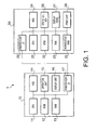
- Fig. 1 is a block diagram showing a configuration of an image forming system according to the embodiment of the invention.
- Figs. 2A-2C show a configuration of color adjustment parameters and how to use the parameters.
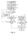
- Fig. 3 is a flowchart showing a color adjustment parameter editing process in the first embodiment.
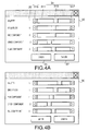
- Figs. 4A and 4B show a configuration of the color adjustment parameter editing screen in the first embodiment.
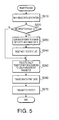
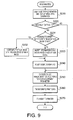
- Fig. 5 is a flowchart showing a print process in the first embodiment.
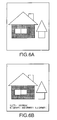
- Fig. 6A shows an example of a main image.
- Fig. 6B shows an example of a print image in which the main image shown in Fig. 6A with the addition of an information image.
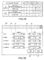
- Fig. 7A shows a configuration of color adjustment parameters in the second embodiment.
- Fig. 7B shows a color adjustment parameter editing screen in the second embodiment.
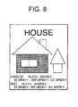
- Fig. 8 is an example in which the information image is added to the main image.
- Fig. 9 is a flowchart showing a print process in the third embodiment.
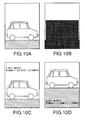
- Fig. 10A is an example of a main image.
- Fig. 10B shows an image area of the main image.
- Fig. 10C is an example of a print image when the information image is inserted to the marginal space of the main image.
- Fig. 10D shows an example of a printed image in the case that the information image is inserted to the predetermined location of the main image.
- Fig. 11 shows a configuration of a color adjustment parameter editing screen in the fourth embodiment.
- Fig. 12 is a flowchart showing a color adjustment parameter editing process.
- Fig. 13 is a flowchart showing a print process according to the fourth embodiment.
- Fig. 14A shows a configuration of color adjustment parameters in the fifth embodiment.
- Fig. 14B shows a configuration of a color adjustment parameter editing screen.
- Fig. 15 is a flowchart showing a color adjustment parameter editing process in the fifth embodiment.
- Fig. 16 is a flowchart showing a print process in the fifth embodiment.
- Fig. 17 shows an example of a printed-application list.
- Fig. 18 is a flowchart showing a print process according to a modification of the first embodiment.
- Hereinafter, referring to the accompanying drawings, embodiments according to the invention are described.
- Fig. 1 is a block diagram showing a configuration of an
image forming system 1 according to the invention. As shown in Fig. 1, theimage forming system 1 is provided with apersonal computer 10, as one example of an information processing device, with which documents and images are created/edited, and further, print data representing bitmap data which developed based on the edited documents and images is generated. Theimage forming system 1 also includes aprinter 20 as one example of a printing device which executes printing according to print data generated by thepersonal computer 10. - The
personal computer 10 is configured mainly with a widely known micro computer which includes a CPU (Central Processing Unit) 11, a ROM (Read Only Memory) 12, a RAM (Random Access Memory) 13, an HDD (Hard Disk Drive) 14. Further, the personal computer is provided with adisplay unit 16 which has an LCD (Liquid Crystal Display) or a CRT (Cathode Ray Tube) that displays images and characters, anoperation unit 15 which has a mouse for moving a pointer that indicates a specific part of thedisplay unit 16 and a key board for inputting characters and symbols, etc., and a printer port I/F (Interface) 17 for connecting theprinter 20 to thepersonal computer 10 through a connecting cable. - The
HDD 14 stores application programs used for generating documents and drawings, and a program which generates image data for printing from the documents and drawings generated by the application programs. - According to the embodiment, the
HDD 14 has a memory area where current setting values of color adjustment parameters which are used in adjusting colors of images to be printed by theprinter 20, and a memory area for storing initial values (setting values before editing) which are necessary in editing color adjustment parameters (described later). - Fig. 2A schematically shows a structure of the memory area for storing the color adjustment parameters. The color adjustment parameters are relative values (in the embodiment, values between -31 and +31) with respect to a preliminarily setup default values (=0) which represent respective intensity of palette, brightness, and color components (red, green, blue).
- The
printer 20 is also configured with mainly a widely known micro computer which includes aCPU 21, aROM 22, aRAM 23 and anHDD 24. Theprinter 20 further includes anonvolatile RAM 25 which stores various setup information, etc., which is input by a user, anoperation keys 26 which are used to select functions theprinter 20 has, adisplay panel 27 which displays contents of operation and/or status of operation, a print unit which prints characters and images, in color, on a printing sheet such as papers, and a printer port I/F 29 for connecting theprinter 20 to thepersonal computer 10 via a connection cable. - Next, processes for color adjustment of images to be printed by the
printer 20 will be described referring to flowcharts. The processes are performed as corresponding programs are executed by theCPU 11 of thepersonal computer 10. - Fig. 3 is a flowchart showing a color adjustment parameter editing process. The process is activated when a color adjustment parameter editing function is designated by an user through an
operation unit 15 of thepersonal computer 10. - When the process is activated, as can be seen in Fig. 3, firstly, in S 110, current setting values of color adjustment parameters stored in the
HDD 14 are copied to the initial value area (see Figs. 2A and 2B: Fig. 2A showing a status before copying, and Fig. 2B showing a status after copying). In S120, a color adjustment parameter editing screen (hereinafter, referred to as "editing screen") is displayed on thedisplay unit 16. - As shown in Figs. 4A and 4B, the
editing screen 30 includes five (5) slider bars 31 respectively corresponding to the adjustment parameters (palette, brightness, red component, green component and blue component),display areas 33 for displaying numerical values set with the slider bars 31, anenter button 35 which is operated (e.g., clicked using the mouse) when numerical values changed using the slider bars 31 are stored and editing is finished, and a cancelbutton 37 which is operated (clicked using the mouse) when editing is to be finished without storing the changed numerical values. - Each of the slider bars is of a well known type and has a
movable pointer 313 which moves from side to side within aframe 311, adecrease button 315 and anincrease button 317 which are placed on either side of theframe 311. The parameter value is increased or decreased by a predetermined amount for every operation (click) of the increase button or the reduction button and thepointer 313 is moved to the location corresponding the parameter value. - An initial display location of the
pointer 313 of theslider bar 31 is a location corresponding to the current setup value of the color adjustment parameter corresponding to theslider bar 31, which is stored in theHDD 14. The slider bars 31, theenter button 35 and the cancelbutton 37 are operated through the operation unit 15 (i.e., a key board and/or a mouse). - In
S 130, the process judges whether one of the slider bars 31 is operated. When theslider bar 31 is operated, the process goes to S 140, updates a numerical value displayed in the display area of the editing screen according to the status of theslider bar 31, and goes back toS 130. - When the
slider bar 31 is not operated, the process goes to S150, and judges whether thebutton 35 is clicked. If the determinebutton 35 has been clicked, the process goes to S 170, settings of the editing screen are reflected to the current setting values of the color adjustment parameters. For example, if theediting screen 30 is changed from a status shown in Fig. 4A to a status shown in Fig. 4B, the current setup value of the color adjustment parameters stored in theHDD 14 are updated from the status shown in Fig. 2B to the status shown in Fig. 2C. - In S 180, the process judges whether the current setting values are the same as the initial values which are set in S110. hen, if the current setting values are different from the initial values, the process goes to
S 190, sets a change flag to indicate that the color adjustment parameters have been changed, and the process is terminated. If the current setting values are the same as the initial values, since the color adjustment parameters have not been changed, the process is terminated without doing anything. - In S150, if the
enter button 35 has not been clicked, the process goes to S160, where the process judges whether the cancelbutton 37 has been clicked. If the cancelbutton 37 has not been clicked, the process goes back to S130. When theclick button 37 has been clicked, the process is terminated without doing anything. - As described above, when the color adjustment parameters are changed, the
editing screen 30 is displayed, and theenter button 35 is clicked after setting up each parameter to a desired value by manipulating the slider bars 31 in theediting screen 30. Further, when the color adjustment parameters have been changed, the change flag is automatically set. - Fig. 5 is a flowchart showing a print process for generating print data to be transmitted to the
printer 20. - The print process is activated when print instructions are received from various applications executed by the
personal computer 10. When the print process is activated, as shown in Fig. 5, firstly, in S210, image data from which the print data is generated (hereinafter, referred to "main image data") is generated. Specifically, a painting process is executed according to the print instruction, and data which represents palette, brightness, intensity of each of the R (red), G (green), B (blue) components in a value represented by a multiple steps (e.g., 256 step values) for each pixel is generated. - Next, in S220, the process judges whether the change flag has been set. When the change flag is set, as the color adjustment parameters have been changed, the process goes to S230. When the change flange is not set, as the color adjustment parameters have not been changed, the process goes to S250.
- In S230, image data which is to be printed with predetermined color characters according to contents of the current setting values of the color adjustment parameters (hereinafter, referred to "information image data") is generated and combined with the main image data generated in S210. Next, in S240, the change flag is reset (i.e., set to represent that the change has not been made), and the process goes to S250.
- It is noted that the information image data is generated so that an information image (image printed according to the information image data) is placed at a predetermined location within a main image (an image printed according to the main image data). For example, when Fig. 6A is a main image, an information image (i.e., an image where settings of the color adjustment parameters are represented with letters/characters) is located in a lower part of the main image as shown in Fig. 6B.
- In S250, color transformation of the image data is executed according to the current setting values of the color adjustment parameters. Then, in S260, the color transformed image data is transformed to print data (bitmap data). In particular, data represented by R, G, B components is transformed data represented by Y (yellow), M (magenta), C (Cyan), K(black) components, and the data is further transformed into data which the
printer 20 can read. A data compression is also executed in S260. - Then, in S270, the print data is transmitted to the
printer 20 through the printer port I/F 17, and the process is terminated. Meanwhile, theprinter 20 which has received the print data executes printing operation according to the received print data. With this printing operation, an image which is the main image associated with the information image is obtained when the color adjustment parameters are changed as shown in Fig. 6B. When the color adjustment parameters have not been changed, an image consists of the main image is obtained as shown in Fig. 6A. - As described above, by using the
image forming system 1, if the color adjustment parameters have been changed, since the image printed based on the print request by the application is printed together with information on color adjustment parameters, typical (i.e., conventional) test patterns are not necessarily printed separately, and a work load can be reduced in color adjustment. - Next, a second embodiment is explained.
- In the second embodiment, the only differences with respect to the first embodiment are: configuration of color adjustment parameters stored in the
HDD 14; configuration of editing screen which is displayed in the color adjustment parameter editing process S120; data format of the information image data which is composed with the main image data in the print process S230; and contents of color transformation process which is executed in the print process S250. Therefore, the same configurations as in the first embodiment are given the same symbols/step numbers, and only the different portions will be explained. - Fig. 7A shows a configuration of color adjustment parameters according to the second embodiment. Fig. 7B is an illustration which shows a configuration of an editing screen according to the second embodiment.
- As can been seen in Fig. 7A, the adjustment parameters are prepared separately for characters and for images. It should be noted that "characters" here includes letters, symbols and the like. The
HDD 14 has the current setting value area and initial value (setting values before editing) area for each of the "characters" and "images." - As shown in Fig. 7B, the
editing screen 30A is configured similarly as theediting screen 30 in the first embodiment, except that the slider bars 31 include totally 10 bars, five bars each for color adjustment parameters of characters and color adjustment parameters of images. - Namely, the
editing screen 30A is configured such that the user can set up color adjustment parameters separately for characters and for images. - Then, the information image which is composed with the main image in the print process S230, as can be seen in Fig. 8, indicates two kinds of color information parameters. The indication is to clearly identify the correspondence between two sets of color information parameters and characters or images, respectively.
- In the print process S250, as shown in Fig. 8, if the main image has both of character part (a part "HOUSE" in Fig. 8) and image part (other parts), regarding image data corresponding to the character part, by using color adjustment parameters for characters, color transformation is executed, and regarding image data corresponding to the image part, by using color adjustment parameters for image, color transformation is executed.
- According to the second embodiment, the
image forming system 1 enables the user to set the color adjustment parameters for characters and color adjustment parameters for images separately Therefore, it is possible to make color adjustment in more detailed manner within the same image. - Next, a third embodiment according to the invention is explained.
- In the third embodiment, since only a part of print process is different from that of the first embodiment, the difference of the print process is mainly explained.
- Fig. 9 is a flowchart showing the print process according to the third embodiment.
- As can be seen in Fig. 9, the step S210 in the first embodiment has been changed to a step S215, and the step S230 in the first embodiment has been changed to steps S231 to S233. Other steps of the print process are similar to the process in the first embodiment.
- When the print process according to the third embodiment is started, firstly, in S215, main image data is generated, and further, drawing area data is generated. The drawing area data is an image data representing an area (i.e., a drawing area) where characters or figures are formed in the main image. For example, in the case that the main image is an image shown in Fig. 10A, the area which is hatched as shown in 10B is the drawing area.
- In S231, the process judges whether information image is to be inserted (or can be inserted) to the other part besides drawing area (i.e., marginal area of the main image). Then, if the information image is to be inserted in the marginal area (or can be inserted in the marginal area), the process goes to S232. In S232, the information image data is combined with the main image data so that the information image is inserted in the marginal area of the main image (see Fig. 10C). On the other hand, if the information image is not to be inserted in the marginal area (or cannot be inserted in the marginal area), the process goes to S233. In S233, the information image data is combined with the main image data so that the information image is inserted in the predetermined fixed area of the main image. In this example, the predetermined fixed area is a lower part of the main image (see Fig. 10D).
- According to the third embodiment, if the information image is inserted in the marginal area of the main image, the user can recognize both the main image and the information image easily.
- Next, a fourth embodiment is explained.
- In the fourth embodiment, configuration of editing screen displayed in color adjustment parameter editing process S120, and parts of color adjustment parameter editing process and print process are different from those of the first embodiment. Therefore, the same configurations in the first embodiment are given the same symbols/step numbers without further explanation, and the different portions are mainly explained. It should be noted that there is a case where a print quality is preferably determined based on a plurality of print images which are printed based on a plurality of pieces of different main image data. The fourth embodiment is configured such that the information image is printed repeatedly.
- Fig. 11 is an illustration showing a configuration of the
editing screen 30B according to the fourth embodiment. - As shown in Fig. 11, the
editing screen 30B is configured similar to theediting screen 30 except that atext box 39 to set the number of printing the information image together with the main image (hereinafter, referred to as a "parameter print count") is added when the color adjustment parameters are changed. - Fig. 12 is a flowchart showing the color adjustment parameter editing process according to the fourth embodiment.
- As shown in Fig. 12, the color adjustment parameter editing process according to the fourth embodiment is different compared to the color adjustment parameter editing process according to the first embodiment in that steps S 143, S 145 have been newly added, steps S 180,
S 190 have been changed to a step S191, andediting screen 30B is displayed inprocess S 120. - Then, in the process shown in Fig. 12, when the process judges that the slider bars 31 are not operated in S130, the process goes to S143, the process judges whether an operation to input parameter print count to the
text box 39 is executed. When the slider bars 31 have not been operated, the process goes to S150. - If the operation to input parameter print count to the
text box 39 is done, the process goes to S145. According to the input value, the number displayed in thetext box 39 of theediting screen 30B is updated, and the process goes back to S130. - In S191, a change flag is not set, but the number displayed in the
text box 39, i.e., the parameter print count, is stored, and the process shown in Fig. 12 is terminated. - As described above, not only color adjustment parameters but also the parameter print count can be set using the
editing screen 30B. When theenter button 35 is clicked, not only setup contents of the slider bars 31 are reflected to the current setting values of the color adjustment parameters, but also the number indicated in thetext box 39 are stored as the parameter print count. - Fig. 13 is a flowchart showing a print process according to the fourth embodiment.
- As shown in Fig. 13, the print process according to the fourth embodiment is different compared to the print process of the first embodiment in that the step S220 has been changed to a step S225, and the step S240 has been changed to a step S245.
- When the main image has been generated in S210, in S225, the process judges whether the parameter print count is greater than 0. If the parameter print count is greater than 0, the information image data is combined with the main image data in S230. Then, the parameter print count is reduced (decremented) by one in S245, and the process goes to S250.
- If the parameter print count is equal to or less than 0, the information image will not be inserted to the main image, and the process goes to S250 without doing any operation. Namely, when the color adjustment parameters have been changed, the information image is inserted into the main image repeatedly, by the time indicated by the parameter print count. Thus, the indications of color adjustment parameters are printed over the main image.
- According to the fourth embodiment, the usability of the image forming system is improved, since a user can set a desired number of times, by which the contents of the color adjustment parameters are printed repeatedly over the main image.
- Next, a fifth embodiment of the invention will be explained.
- In the fifth embodiment, a configuration of color adjustment parameters stored in the
HDD 14, a configuration of editing screen displayed in color adjustment parameter editing process, a color adjustment parameter editing process, and a print process are different from corresponding configurations of the first embodiment. - Fig. 14A shows a configuration of data structure of the color adjustment parameters according to the fifth embodiment. Fig. 14B shows a configuration of an
editing screen 30C according to the fifth embodiment. - As can been seen in Fig. 14A, the adjustment parameters are prepared separately for each application. The
HDD 14 has areas to store the current setting values of each application ("WORD PROCESSOR", "DRAWING", "OTHERS"), and areas, which are commonly used, to store initial values (i.e., initial values before setting) of the application for which the adjustment parameters are being set. TheHDD 14 has also areas storing the change flags for respective applications. - As shown in Fig. 14B, the
editing screen 30C is configured similarly to theediting screen 30 in the first embodiment except that atext box 34 to indicate an application of which color adjustment parameters to be changed is added. - That is, on the
editing screen 30C, it is possible to select one of application, and change color adjustment parameters which are used when prating is executed according to print instructions from the application. - Fig. 15 is a flowchart which shows the color adjustment parameter editing process according to the fifth embodiment.
- When the process shown in Fig. 15 is activated, firstly, in S310, current setting values of color adjustment parameters of the predetermined application are copied to the area for storing the initial values. Next, in S320, an
editing screen 30C where the current setting values of the predetermined application are reflected is displayed on thedisplay unit 16. - The predetermined application may be any application setup preliminarily, or may be an application which was indicated when the
enter button 35 was clicked in a previous setting operation. - Next in S330, the process judges whether an operation to switch an application is executed using the
text box 34. When such an operation is executed, the process goes to S340, the current setting values of the color adjustment parameters are copied to the initial value area, the current setting values are reflected to theediting screen 30C, and the process returns to S330. - When the operation to switch the application is not executed (S330: NO), the process goes to S350, and the process judges whether the slider bars 31 are operated. If the slider bars 31 are operated, the process goes to S360, numerical values indicated in the
display areas 33 of the editing screen are updated according to the status of the operated slider bars 31. If the slider bars 31 are not operated (S350: NO), the process goes to S370. - In S370, the process judges whether the
enter button 35 is clicked. If theenter button 35 is clicked, the process goes to S390, contents of theediting screen 30C are reflected to the current setting values of the color adjustment parameters of the application which is indicated in the text box 34 (hereinafter, referred to "selected application"). - Next, in S400, the process judges whether the current setting values are equal to the initial values set in S310 or S340. If the current setting values are equal to the initial values, since the color adjustment parameters have not been changed, the process is terminated without doing any operation.
- If the current setting values are different from the initial values (S400: NO), the process goes to S410, and the change flag of the selected application is set in order to show the color adjustment parameters have been changed. Next, in S420, the process judges whether the selected application is "OTHERS".
- If the selected application is not the "OTHERS", the process is terminated without doing anything. If the selected application is the "OTHERS", if the selected application is indicated in a print processed-application list, the indication in the list is cleared, and the process is terminated. The print processed-application list is a list indicating the applications with which printing operations have been executed with the color adjustment parameters being used. Fig. 17 shows an example of the print processed-application list.
- In previous S37, if it is determined that the
button 35 has not been clicked, the process goes to S380, and judges whether a cancelbutton 37 is clicked. If the cancelbutton 37 has not been clicked, the process returns to S330. If the cancelbutton 37 has been clicked, the process is terminated without doing anything. - In the above-described process, via the
editing screen 30C, it is possible to set the color adjustment parameters for each of application, and the application of which the color adjustment parameters have been changed is deleted from the print processed-application list. - Fig. 16 is a flowchart showing the print process according to the fifth embodiment.
- When the print process is activated, in S510, the image data from which the print data (i.e., the main image data) is generated is generated. Next, in S520, the process judges whether there exist the color adjustment parameters of an application which has issued a print instruction (hereinafter, referred to "requiring application"). If there exists such an application, the process goes to S530.
- In S530, the process judges whether the change flag regarding the color adjustment parameters of the requiring application has been set. If the change flag has been set, since the color adjustment parameters have been changed, the process goes to S540. If the change flag is not set, since the color adjustment parameters have not been changed, the process goes to S600.
- In S540, the image data (information image data) to be printed with characters in accordance with the preliminarily setup color is generated according to the contents of current setting values of color adjustment parameters related to the requiring application. The image data is then combined with the main image data generated in previous S510. Next, in S550, the change flag related to the color adjustment parameters of the requesting application is reset (released), and the process goes to S600.
- If it is determined that there are no color adjustment parameters related to the requiring application (S520: NO), the process goes to S560 and judges whether the change flag related to the color adjustment parameters of an application of which a kind is "OTHERS" is set.
- If the change flag is set, since the color adjustment parameters related to "OTHERS" have been changed, the process goes to S570. If the change flag is not set, since the color adjustment parameters related to "OTHERS" have not been changed, the process goes to S600.
- In S570, it is determined whether the requiring application is included in the print processed-application list. If the application is included in the list, since it is not necessary for the information image to be inserted to the main image, the process goes to S600. If the application is not included, since it is necessary for the information image to be inserted to the main image, the process goes to S580.
- In S580, the information image data to be printed with characters having a preliminarily set color is generated according to the current setting values of color adjustment parameters for the application categorized in "OTHERS." Then, the information image data is combined with the main image data generated in S510. Next, in S590, the requesting application is added to the print processed-application list, the change flag related to color adjustment parameters the application categorized in "OTHERS" are reset, and the process goes to S600.
- In S600-S620, similarly in S250-270 of the first embodiment, the color transformation is executed according to the current setting values of the color adjustment parameters corresponding to the requiring application (S600). Then, the color-transformed image data is transformed into the print data (S610). The print data is then transmitted to the
printer 20 via the printer port I/F 17 (S620), and the process is terminated. - According to the fifth embodiment, the color adjustment parameters can be set for each kind of applications. Therefore, it is possible to adjust image quality according to characteristics of each application.
- In the embodiment, a type of "OTHERS" is included in a categorization of applications. It may be modified such that a new categorization can be registered when there is no appropriate category is included in the selectable candidates.
- It should be noted that the invention is not limited to the above-described illustrative embodiments. Various embodiments/modifications can be made within the scope of the invention.
- For example, in the above described embodiments, transformation of image data to print data is executed by the
personal computer 10. This configuration may be modified such that the transformation is performed by theprinter 20. In such a case, the color adjustment parameters necessary for transformation may be transmitted to theprinter 20 together with the image data. - In the above embodiments, the information image is printed on the same side of the printing sheet where the main image is printed. If the
printer 20 can print both sides of the printing sheet and the main image is printed only one side thereof, the information image may be printed on the other side of the sheet. - Fig. 18 shows an example of such a modification. That is, Fig. 18 is a modified print process which is a modification of the print process shown in Fig. 5. In Fig. 18 and description below, the steps that are the same as those of Fig. 5 are assigned to the same step number used in Fig. 5 and description thereof is omitted for brevity.
- S710 corresponds to S210 of Fig. 5. In S710, the process generates main image data to be printed on the front side of the printing sheet. After execution of S710, steps S250 and S260 follow, which are similar to those in Fig. 5. Then, the process judges whether the modification flag is set (S220). If the modification flag is not set (S220: NO), the process proceeds to S270 and then the process is terminated. If the modification flag is set (S220: YES), the process proceeds to S730, in which the information image data to be printed on the back side of the printing sheet is generated. Then, in S240-S250 are executed so that the information image is transformed to the print data, which is also transmitted to the printer.
Claims (16)
- An image forming system, comprising:a setting unit configured to allow a user to set color adjustment parameters to be used to print out main image data;an information image data generating unit configured to generate information image data representing contents of the color adjustment parameters set with the setting unit;a combining unit configured to combine the information image data with the main image data to generate combined image data; anda printing unit configured to print an image based on the combined image data with the color being adjusted in accordance with the color adjustment parameters set by the setting unit.
- The image forming system according to claim 1,
wherein the color adjustment parameters are set for each of types of applications used for generating the main image data. - The image forming system according to claim 1 or 2,
wherein the color adjustment parameters are set for each of attributes of the main image data. - The image forming system according to claim 3,
wherein the information image shows contents of the color adjustment parameters for each of the attributes. - The image forming system according to any one of claims 1 to 4,
wherein the combining unit combines the information image data to the main image data such that the information image as printed has a predetermined positional relationship with the main image as printed. - The image forming system according to any one of claims 1 to 4,
wherein the combining unit combines the information image data to the main image data such that the information image is printed in an area of the printing sheet where the main image is not printed. - The image forming system according to any one of claims 1 to 6,
wherein the printing unit is configured to be able to print on both sides of the printing sheet; and
wherein, if the main image is printed only on one side of the printing sheet, the combining unit combines the information image data so that the information image is printed on the other side of the printing sheet. - The image forming system according to any one of preceding claims,
wherein the combining unit combines the information image data with the main image data only when the color adjustment parameters have been changed. - The image forming system according to any one of preceding claims,
wherein the combining unit combines the information image data with the main image data by a predetermined number of times. - The image forming system according to claim 9, further comprising a count setting unit configured to set the number of times by which the information image data is to be combined with the main image data.
- The image forming system according to any one of preceding claims,
wherein characters contained in the information image are printed in a predetermined color. - A method of printing an image, comprising the steps of:generating information image data representing contents of the color adjustment parameters set by the user;combining the information image data with the main image data to generate combined image data;printing the image based on the combined image data with the color being adjusted in accordance with the color adjustment parameters set by the setting unit.
- The method according to claim 12,
wherein the combining step combines the information image data to the main image data such that the information image is printed in an area of a printing sheet where the main image is not printed. - The method according to claim 12 or 13,
wherein the combining step combines the information image data with the main image data only when the color adjustment parameters have been changed. - The method according to claim 12, 13 or 14,
wherein the combining step combines the information image data with the main image data by a predetermined number of times. - A computer program containing computer-readable instructions that cause, when executed by a computer, a computer to execute the method according to any one of claims 11-15.
Applications Claiming Priority (1)
| Application Number | Priority Date | Filing Date | Title |
|---|---|---|---|
| JP2006265325A JP2008085845A (en) | 2006-09-28 | 2006-09-28 | Image forming method |
Publications (2)
| Publication Number | Publication Date |
|---|---|
| EP1906648A2 true EP1906648A2 (en) | 2008-04-02 |
| EP1906648A3 EP1906648A3 (en) | 2009-06-03 |
Family
ID=38896061
Family Applications (1)
| Application Number | Title | Priority Date | Filing Date |
|---|---|---|---|
| EP07253812A Withdrawn EP1906648A3 (en) | 2006-09-28 | 2007-09-26 | Image forming system |
Country Status (4)
| Country | Link |
|---|---|
| US (1) | US8437042B2 (en) |
| EP (1) | EP1906648A3 (en) |
| JP (1) | JP2008085845A (en) |
| CN (1) | CN101154148A (en) |
Families Citing this family (4)
| Publication number | Priority date | Publication date | Assignee | Title |
|---|---|---|---|---|
| JP5193992B2 (en) * | 2009-12-25 | 2013-05-08 | 京セラドキュメントソリューションズ株式会社 | Image processing apparatus and image processing program |
| US20140176967A1 (en) * | 2012-12-20 | 2014-06-26 | Hewlett-Packard Development Company, L.P. | Colorimetric rendering |
| JP6326988B2 (en) * | 2014-06-05 | 2018-05-23 | 富士ゼロックス株式会社 | Image processing apparatus and image processing program |
| US9256817B1 (en) | 2015-03-19 | 2016-02-09 | Kabushiki Kaisha Toshiba | Image forming apparatus, method and computer readable medium specifying condition for converting printing colors into multi-color component data with special color added |
Citations (5)
| Publication number | Priority date | Publication date | Assignee | Title |
|---|---|---|---|---|
| JPH03114852A (en) * | 1989-09-29 | 1991-05-16 | Mitsubishi Electric Corp | Printer |
| JPH06258907A (en) * | 1993-03-08 | 1994-09-16 | Canon Inc | Color image forming device |
| EP0772116A1 (en) * | 1995-10-31 | 1997-05-07 | Seiko Epson Corporation | Computer calibration of a color print image using successive refinement |
| US6351263B1 (en) * | 1992-07-28 | 2002-02-26 | Canon Kabushiki Kaisha | Image processor which manually and independently designates processing parameters for character data and image data |
| US20020131070A1 (en) * | 2001-03-16 | 2002-09-19 | Housel Edward M. | Using e-mail to facilitate soft proofing and for print job status |
Family Cites Families (17)
| Publication number | Priority date | Publication date | Assignee | Title |
|---|---|---|---|---|
| DE3219744A1 (en) * | 1982-05-26 | 1983-12-01 | Heidelberger Druckmaschinen Ag, 6900 Heidelberg | EQUIPMENT FOR STANDALIZED AND FIT FILM ASSEMBLY OF PRINT CONTROL STRIPS |
| ATE58336T1 (en) * | 1983-12-19 | 1990-11-15 | Gretag Ag | METHOD, DEVICE AND COLOR STRIPS FOR ASSESSING PRINT QUALITY. |
| JPH0787318A (en) | 1992-07-28 | 1995-03-31 | Canon Inc | Image processor and image forming device |
| DE4418782C2 (en) * | 1993-05-21 | 1997-01-09 | Mitsubishi Electric Corp | System and method for adjusting a color image |
| US7027187B1 (en) * | 1995-08-07 | 2006-04-11 | Electronics For Imaging, Inc. | Real time calibration of a marking engine in a print system |
| JPH10322562A (en) | 1997-05-15 | 1998-12-04 | Fuji Photo Film Co Ltd | Color conversion adjusting method |
| US6297800B2 (en) * | 1998-09-08 | 2001-10-02 | Dazzle Multimedia, Inc. | Performing color adjustments on image data |
| US6317848B1 (en) * | 1998-09-24 | 2001-11-13 | Xerox Corporation | System for tracking and automatically communicating printer failures and usage profile aspects |
| JP2000217007A (en) | 1999-01-25 | 2000-08-04 | Nec Corp | Device and method for color printing and storage medium recording color print program |
| US6972856B1 (en) * | 1999-03-11 | 2005-12-06 | Canon Kabushiki Kaisha | Querying of copyright host, printing of copyright information and host registration of copyright data |
| US7092116B2 (en) * | 2000-06-29 | 2006-08-15 | Douglas Calaway | Method and system for processing an annotated digital photograph using a composite image |
| US7253917B2 (en) * | 2001-06-11 | 2007-08-07 | Canon Kabushiki Kaisha | Image processing apparatus and its control method, computer program, and storage medium |
| JP2004206689A (en) * | 2002-12-11 | 2004-07-22 | Fuji Photo Film Co Ltd | Image retouch device and image retouch program |
| JP2004364115A (en) * | 2003-06-06 | 2004-12-24 | Konica Minolta Business Technologies Inc | Original reader, image forming device and image processing method |
| JP4116957B2 (en) | 2003-09-10 | 2008-07-09 | 株式会社リコー | Image forming apparatus |
| JP2005267485A (en) | 2004-03-22 | 2005-09-29 | Canon Inc | Image forming system |
| US20060103887A1 (en) * | 2004-11-18 | 2006-05-18 | Fuji Photo Film Co., Ltd. | Printer and print |
-
2006
- 2006-09-28 JP JP2006265325A patent/JP2008085845A/en active Pending
-
2007
- 2007-09-26 EP EP07253812A patent/EP1906648A3/en not_active Withdrawn
- 2007-09-28 CN CNA2007101616701A patent/CN101154148A/en active Pending
- 2007-09-28 US US11/905,230 patent/US8437042B2/en active Active
Patent Citations (5)
| Publication number | Priority date | Publication date | Assignee | Title |
|---|---|---|---|---|
| JPH03114852A (en) * | 1989-09-29 | 1991-05-16 | Mitsubishi Electric Corp | Printer |
| US6351263B1 (en) * | 1992-07-28 | 2002-02-26 | Canon Kabushiki Kaisha | Image processor which manually and independently designates processing parameters for character data and image data |
| JPH06258907A (en) * | 1993-03-08 | 1994-09-16 | Canon Inc | Color image forming device |
| EP0772116A1 (en) * | 1995-10-31 | 1997-05-07 | Seiko Epson Corporation | Computer calibration of a color print image using successive refinement |
| US20020131070A1 (en) * | 2001-03-16 | 2002-09-19 | Housel Edward M. | Using e-mail to facilitate soft proofing and for print job status |
Also Published As
| Publication number | Publication date |
|---|---|
| US8437042B2 (en) | 2013-05-07 |
| US20080079969A1 (en) | 2008-04-03 |
| CN101154148A (en) | 2008-04-02 |
| EP1906648A3 (en) | 2009-06-03 |
| JP2008085845A (en) | 2008-04-10 |
Similar Documents
| Publication | Publication Date | Title |
|---|---|---|
| US6798530B1 (en) | Systems, methods and graphical user interfaces for printing object optimized images using virtual printers | |
| JP3591129B2 (en) | Display characteristic function determining method for display, display characteristic function determining device for display, γ value determining device, and printer system | |
| US5717838A (en) | Computer calibration of a color print image using successive refinement | |
| EP2136291A2 (en) | Image forming system, image forming method and image forming apparatus | |
| US20200210117A1 (en) | Image processing device and non-transitory computer-readable storage medium storing image processing program | |
| US7623737B2 (en) | Information processing apparatus, control method and control program for registration of information related to ground tint | |
| JP2022122166A (en) | Print control device, print control method, and program | |
| JP2022122128A (en) | Print control device, print control method, and program | |
| EP1906648A2 (en) | Image forming system | |
| JP3719058B2 (en) | Print control device | |
| JP2006192580A (en) | Previewing device, previewing program and previewing method | |
| JP7110840B2 (en) | Program, image forming apparatus, information processing apparatus, and information processing system | |
| KR100653054B1 (en) | Printing system and printing method | |
| CN110879691B (en) | Computer, image forming apparatus, information processing apparatus, and information processing system | |
| KR100571788B1 (en) | The method of printing the appointed domain of document enlargeably | |
| JP7005796B2 (en) | Image forming device, its control method, and program | |
| JP2018200658A (en) | Information processing apparatus, information processing method, and program | |
| JP2013051639A (en) | Image formation means | |
| JP2006180388A (en) | Image processor and monochromatic color judgment method therefor | |
| JP2022171061A (en) | Print control device, print control method, and program | |
| JP4337836B2 (en) | Image forming system, information terminal device, program | |
| JP5795248B2 (en) | Printing condition determining apparatus, printing condition determining method and program | |
| JP3149877B2 (en) | Color printer controller | |
| JP2021141440A (en) | Image forming apparatus | |
| JP4991429B2 (en) | Coloring material usage reduction program |
Legal Events
| Date | Code | Title | Description |
|---|---|---|---|
| PUAI | Public reference made under article 153(3) epc to a published international application that has entered the european phase |
Free format text: ORIGINAL CODE: 0009012 |
|
| AK | Designated contracting states |
Kind code of ref document: A2 Designated state(s): AT BE BG CH CY CZ DE DK EE ES FI FR GB GR HU IE IS IT LI LT LU LV MC MT NL PL PT RO SE SI SK TR |
|
| AX | Request for extension of the european patent |
Extension state: AL BA HR MK YU |
|
| PUAL | Search report despatched |
Free format text: ORIGINAL CODE: 0009013 |
|
| AK | Designated contracting states |
Kind code of ref document: A3 Designated state(s): AT BE BG CH CY CZ DE DK EE ES FI FR GB GR HU IE IS IT LI LT LU LV MC MT NL PL PT RO SE SI SK TR |
|
| AX | Request for extension of the european patent |
Extension state: AL BA HR MK RS |
|
| AKX | Designation fees paid | ||
| REG | Reference to a national code |
Ref country code: DE Ref legal event code: 8566 |
|
| STAA | Information on the status of an ep patent application or granted ep patent |
Free format text: STATUS: THE APPLICATION IS DEEMED TO BE WITHDRAWN |
|
| 18D | Application deemed to be withdrawn |
Effective date: 20091204 |