EP1907308B2 - Wire guiding sheath - Google Patents
Wire guiding sheath Download PDFInfo
- Publication number
- EP1907308B2 EP1907308B2 EP06794491.8A EP06794491A EP1907308B2 EP 1907308 B2 EP1907308 B2 EP 1907308B2 EP 06794491 A EP06794491 A EP 06794491A EP 1907308 B2 EP1907308 B2 EP 1907308B2
- Authority
- EP
- European Patent Office
- Prior art keywords
- guidance
- wire
- support
- type
- supports
- Prior art date
- Legal status (The legal status is an assumption and is not a legal conclusion. Google has not performed a legal analysis and makes no representation as to the accuracy of the status listed.)
- Active
Links
- 230000000712 assembly Effects 0.000 claims abstract description 23
- 238000000429 assembly Methods 0.000 claims abstract description 23
- 238000011144 upstream manufacturing Methods 0.000 claims abstract description 11
- 230000001681 protective effect Effects 0.000 claims description 7
- 238000003860 storage Methods 0.000 claims description 3
- 238000003466 welding Methods 0.000 abstract description 17
- 238000005096 rolling process Methods 0.000 description 15
- 238000004806 packaging method and process Methods 0.000 description 5
- 230000007547 defect Effects 0.000 description 2
- 238000006073 displacement reaction Methods 0.000 description 2
- 230000016571 aggressive behavior Effects 0.000 description 1
- 230000015572 biosynthetic process Effects 0.000 description 1
- 230000000295 complement effect Effects 0.000 description 1
- 230000003750 conditioning effect Effects 0.000 description 1
- 239000000428 dust Substances 0.000 description 1
- 238000004519 manufacturing process Methods 0.000 description 1
- 229910000679 solder Inorganic materials 0.000 description 1
- 239000007787 solid Substances 0.000 description 1
Images


Classifications
-
- B—PERFORMING OPERATIONS; TRANSPORTING
- B65—CONVEYING; PACKING; STORING; HANDLING THIN OR FILAMENTARY MATERIAL
- B65H—HANDLING THIN OR FILAMENTARY MATERIAL, e.g. SHEETS, WEBS, CABLES
- B65H57/00—Guides for filamentary materials; Supports therefor
- B65H57/12—Tubes
-
- B—PERFORMING OPERATIONS; TRANSPORTING
- B23—MACHINE TOOLS; METAL-WORKING NOT OTHERWISE PROVIDED FOR
- B23K—SOLDERING OR UNSOLDERING; WELDING; CLADDING OR PLATING BY SOLDERING OR WELDING; CUTTING BY APPLYING HEAT LOCALLY, e.g. FLAME CUTTING; WORKING BY LASER BEAM
- B23K9/00—Arc welding or cutting
- B23K9/12—Automatic feeding or moving of electrodes or work for spot or seam welding or cutting
- B23K9/133—Means for feeding electrodes, e.g. drums, rolls, motors
- B23K9/1336—Driving means
-
- B—PERFORMING OPERATIONS; TRANSPORTING
- B65—CONVEYING; PACKING; STORING; HANDLING THIN OR FILAMENTARY MATERIAL
- B65H—HANDLING THIN OR FILAMENTARY MATERIAL, e.g. SHEETS, WEBS, CABLES
- B65H57/00—Guides for filamentary materials; Supports therefor
- B65H57/14—Pulleys, rollers, or rotary bars
Definitions
- the present invention relates to the technical field relating to the supply or transport of a wire, of any kind and section, from a place of packaging to a place of use.
- the object of the invention is more specifically a new sheath inside which moves the wire to be conveyed between the place of packaging and the place of use.
- the object of the invention finds a preferred application in the transport of a welding wire by the need for mobility at the welding zone and the need for protection against external aggression (dust, dirt).
- An additional constraint is related to the fact that the length of the sheath must be relatively small to overcome the wear problems, so that such a constraint limits the design possibilities of the machine incorporating such a sheath.
- patent US 1,898,060 discloses a welding machine incorporating two roller systems mounted perpendicular to each other to straighten the solder wire before use. This patent does not solve the problem of guiding a welding wire between its place of packaging and its place of use.
- the present invention therefore aims to overcome the disadvantages mentioned above by providing a sheath for guiding a wire, adapted to reduce the friction of the wire inside the sheath, even when it is bent in different directions. .
- the object of the invention is also to provide a sheath for guiding a wire, adapted to be of simple design, while ensuring its guiding function of the wire.
- the sheath according to the invention is in accordance with claim 1.
- first and second hinge means are made by a hinge of the same type, such as pivot, ball or elastic.
- At least one of the axes of a rolling member of the second guide assemblies extends in a direction perpendicular to that of at least one axis of a rolling member of the first sets of guiding and in that the first and second hinge means have hinge directions at least perpendicular to each other.
- the axes of the rolling members, forming part of the same guide assembly are parallel to each other.
- the first type of supports of the first guide assemblies are identical to the supports of the second type of the second guide assemblies.
- each support of the guide assemblies is equipped with a guide tube for the wire extending between the guide assembly carried by said support and the guide assembly carried by the upstream or downstream support.
- the guide sheath according to the invention preferably comprises stop means for limiting the articulation amplitude of the first and second articulation means.
- the latter comprises a protective envelope in which are mounted the supports of the first and second guide assemblies.
- the protective envelope incorporates a spring.
- Another object of the invention is to propose a system for feeding a wire by means of drive means, comprising a guide sheath according to the invention disposed between the wire storage location and the place. use of the wire.
- the object of the invention relates to a sheath 1 guiding a wire 2 moving inside the sheath in a guide path 3 , in a direction of movement represented by the arrow F 1 .
- the sheath 1 according to the invention is used with at least one advance system 4 for conveying the wire 2 from a storage or conditioning station 5 1 , 5 2 or 5 3 to a utilization station 6 .
- the feed system 4 comprises drive means 7 of the wire of any type known per se, such as pushed, pulled, pushed-pulled or push-pushed type.
- the drive means 7 will not be described more precisely because they are not part of the object of the invention and are well known to those skilled in the art.
- the wire 2 is solid or hollow and has a section for example circular or other.
- the wire 2 is packaged in different forms, such as in a drum 1 , crown, barrel 5 2 or coil 5 3 , as illustrated in FIG. Fig. 1 .
- the wire 2 is a welding wire guided inside the sheath 1 according to the invention, in order to be conveyed to a utilization station 6 , such as a welding station associated with a robot 8 .
- the sheath 1 according to the invention can thus be used between the welding station 6 and the feed system 4 near which is placed in the illustrated example, the coil 5 3 , or between the welding station 6 and a packaging deported such a barrel 5 2 or a drum 5 1 for example.
- the Fig. 2 to 4 illustrate a first embodiment of a sheath 1 according to the invention comprising a series of supports of the first type 1 for a first guide assembly 11 1 for the wire 2 and a series of second type supports 2 for 2 second guide assemblies 11 2 for the wire.
- the supports of the first type 10 1 and the supports of the second type 10 2 are arranged successively and alternately, so that outside the supports forming the two ends of the sheath, a support of a given type is interposed between two supports of a different type.
- a support of a given type is adjacent or adjacent, on one of its sides, a support of a different type, said upstream, in consideration of the direction of advancement wire and, according to its opposite side, a different support, said downstream.
- each support of a type 10 1 , 10 2 is articulated with each of the adjacent or adjacent supports of a different type.
- each support of a given type for example of the first type 1
- each support of a second type 2 2 is articulated on the one hand, with the aid of the first articulation means 15 with the first type of upstream support 10 1 according to at least one articulation direction A and, secondly, using second hinge means 17 with the first type of downstream support 10 1 according to at least one articulation direction B.
- the articulation means 15, 17 are adapted to allow a movement of the supports between them in at least two articulation directions A, B perpendicular to each other, so that the sheath can follow curvatures extending in planes. different.
- the articulation directions A and B are perpendicular to each other and to the direction of advance of the wire 2 .
- the supports of the first type 1 are identical to the supports of the second type 2 .
- the supports of the first type 1 are angularly offset, along the axis of the sheath, by 90 ° with respect to the supports of the second type 2 .
- the subscripts 1 and 2 of the various components of media will be attached, respectively, to the first media Type 10 1 and the second Type 10 2 supports.
- Each support 10 1 , 10 2 is in the form of a tubular or annular body 20 1 , 20 2 delimiting, internally, a cage 21 1 , 21 2 mounting for a guide assembly 11 1 , 11 2 .
- each guide assembly 11 1 , 11 2 comprises rolling members 23 1 , 23 2 , mounted facing each other in order to define the guide path 3 for the wire 2 .
- Each rolling member 23 1 , 23 2 is rotatably mounted along an axis 25 1 , 25 2 carried by the support 10 1 , 10 2 .
- each guide assembly 11 1 , 11 2 comprises two rolling members 23 1 , 23 2 carried by axes extending parallel to each other.
- Each rolling member 23 1 , 23 2 may be made by a roller or a roller, having a constant circular cross section, as shown in FIG. Fig. 4 , without groove or with a groove 26 , as illustrated in FIG. Fig. 5 or with a retaining lateral rib 27 , as illustrated in FIG. Fig. 6 .
- each guide assembly 11 1 , 11 2 may comprise a number of rolling members different from two, such as three members whose axes are shifted between them by 120 ° to form a guide path 3 of triangular section, as shown in Fig. 7 .
- the spacing of the rolling members 23 1 , 23 2 , placed vis-à-vis to form a guide assembly, is chosen so that the guide path 3 has a passage section greater than the diameter of the wire.
- This passage section is advantageously chosen to allow the passage of son of different diameters. It must be considered that the wire 2 can thus pass freely in the parts of the sheath that are rectilinear or straight, while the wire 2 is in contact with the rolling members located in the parts of the sheath undergoing a curvature.
- Each body 20 1 , 20 2 is advantageously extended, opposite the mounting cage 21 1 , 21 2 , by a guide tube 30 1 , 30 2 for the wire, thus delimiting the guide path 3 for the wire .
- Each guide tube 30 1 , 30 2 thus extends between the guide assembly 11 1 , 11 2 carried by said corresponding support and the guide assembly carried by the downstream support.
- each guide tube 30 1 , 2 ensures guiding continuity for the wire between two adjacent or consecutive guide assemblies 11 1 , 11 2 carried by two supports of different type.
- Each guide tube 30 1 , 2 preferably has a frustoconical longitudinal section which narrows towards the downstream support.
- Each body 20 1 , 20 2 is also provided with two arms 32 1 , 32 2 , extending parallel to each other and on either side of the guide tube 30 1 , 2 .
- the two arms 32 1 , 32 2 are each provided with a receiving orifice 33 1 , 33 2 for respectively a pivot 34 2 , 34 1 arranged on the bodies 20 1 , 20 2 .
- the two receiving orifices 33 1 of a support are aligned and are adapted to receive the two pivots 34 2 of a downstream support for forming the first articulation means 15 , while the two pivots 34 1 of said support with which cooperate the two orifices 33 2 of an upstream support form the second articulation means 17 .
- each joint A, B is located in the vicinity of a guide assembly 11 1 , 11 2 .
- each joint A, B adjacent to a guide assembly, extends substantially parallel to the axis of at least one rolling member belonging to said guide assembly.
- the articulation means 15 have, for example, a hinge direction A which is parallel and close to the axes 25 2 of the neighboring rolling members while the hinge means 17 have a hinge direction B which is parallel and close to the axes 25 1 , neighboring rolling members.
- the sheath 1 comprises stop means 40 adapted to limit the amplitude of the first 15 and second 17 articulation means.
- the limitation means 40 are formed by the guide tube 30 1 , 30 2 of a support adapted to abut on the body of a neighboring support.
- the misalignment between two consecutive media can be limited to a value of the order of 30 °.
- the sheath 1 makes it possible to guide the wire 2 during its advancement via, in particular, the rolling members 23 1 , 23 2 .
- the resistance to the advancement of the wire is due solely to the friction of the rolling member on its axis.
- the guiding of the wire 2 is thus ensured, even if the sheath undergoes displacements, in particular at its place of use, causing changes of curvature in different planes.
- the implementation of the hinge means 15, 17 in two different planes, alternated from one support to the other allows the sheath to follow different conformations.
- all the supports 10 1 , 10 2 can be mounted inside a protective envelope 50, as illustrated in FIG. Fig. 2 .
- This protective envelope 50 may possibly be associated with a spiral spring 51 which, in the example shown, is directly integrated with the protective envelope.
- a spring 51 gives the sheath, a determined stiffness also contributing to ensuring the alignment of the supports together.
- each pivot joint can be replaced by an elastic connection using one or more springs or elastic elements 55, as illustrated in FIG. Fig. 8 interposed between the supports 10 1 , 10 2 .
- each support body 20 1 , 20 2 thus has, on either side, a hemispherical portion 57 1 , 57 2 each cooperating with a complementary and opposite hemispherical portion 57 2 , 57 1 of FIG. a nearby support.
- Each support is thus assembled to each adjacent support, by a ball joint allowing a relative angular displacement of the supports in different directions.
- the supports 10 1 , 10 2 are mounted without mechanical connection to each other but being mounted inside a sheath 50 in which are mounted the supports cooperating with each other by conformations 60 1 , 60 2 , arranged on the supports and cooperating with each other to ensure articulation between two consecutive or neighboring supports.
Abstract
Description
La présente invention concerne le domaine technique relatif à l'amenée ou au transport d'un fil, de toute nature et section, d'un lieu de conditionnement à un lieu d'utilisation.The present invention relates to the technical field relating to the supply or transport of a wire, of any kind and section, from a place of packaging to a place of use.
L'objet de l'invention vise plus précisément une nouvelle gaine à l'intérieur de laquelle se déplace le fil à acheminer entre le lieu de conditionnement et le lieu d'utilisation.The object of the invention is more specifically a new sheath inside which moves the wire to be conveyed between the place of packaging and the place of use.
L'objet de l'invention trouve une application préférée dans le transport d'un fil de soudure par la nécessité de mobilité au niveau de la zone de soudage et le besoin de protection contre les agressions extérieures (poussières, salissures).The object of the invention finds a preferred application in the transport of a welding wire by the need for mobility at the welding zone and the need for protection against external aggression (dust, dirt).
Dans le domaine d'application préférée, il est connu d'utiliser un tuyau souple en plastique à l'intérieur duquel se déplace le fil de soudure entre son conditionnement (en bobine, touret, fût, couronne) et la zone de soudage. L'avance du fil est assurée par un ou plusieurs systèmes de galets motorisés. En fonction des applications, soudage manuel ou robotisé et des longueurs de la gaine, le ou les systèmes d'avancement motorisés seront placés à des endroits différents sur le parcours du fil.In the preferred field of application, it is known to use a plastic hose inside which the welding wire moves between its packaging (coil, drum, barrel, crown) and the welding zone. Feed advance is provided by one or more motorized roller systems. Depending on the application, manual or robotic welding and lengths of the sheath, the motorized advancement system (s) will be placed at different locations along the wire path.
D'une manière générale, il doit être considéré que l'acheminement continu d'un fil de soudure pose de réelles difficultés dues, notamment, à la longueur de la gaine, de la courbure prise par la gaine lors des opérations de soudage, de la tension du fil et du coefficient de frottement entre la gaine et le fil. Il est à noter que le problème de frottement évolue dans le temps et s'aggrave générant des à-coups dans l'avancement du fil, causés par une usure de la gaine et la formation de mini copeaux. Dans certains cas, il se produit un blocage total du fil à l'intérieur de la gaine. Il apparaît ainsi nécessaire de prévoir fréquemment le remplacement de la gaine, ce qui entraîne un surcoût dû au remplacement de la gaine et à l'arrêt du poste de soudage. Par ailleurs, les difficultés d'avancement du fil conduisent fréquemment à des défauts dans la qualité de soudage, nécessitant des coûts supplémentaires, soit pour réparer le défaut, soit pour la mise au rebut des pièces soudées. Une contrainte supplémentaire est liée au fait que la longueur de la gaine doit être relativement faible pour s'affranchir des problèmes d'usure, due sorte qu'une telle contrainte limite les possibilités de conception de la machine intégrant une telle gaine.In general, it must be considered that the continuous routing of a welding wire poses real difficulties due, in particular, to the length of the sheath, the curvature taken by the sheath during welding operations, the tension of the wire and the coefficient of friction between the sheath and the wire. It should be noted that the problem of friction changes over time and worsens generating jolts in the advancement of the wire, caused by wear of the sheath and the formation of mini chips. In some cases, there is a complete blockage of the wire inside the sheath. It thus appears necessary to frequently provide for the replacement of the sheath, which entails an additional cost due to the replacement of the sheath and the stopping of the welding station. Moreover, the difficulties of advancement of the wire frequently lead to defects in the welding quality, requiring additional costs, either to repair the defect or for the scrapping of the welded parts. An additional constraint is related to the fact that the length of the sheath must be relatively small to overcome the wear problems, so that such a constraint limits the design possibilities of the machine incorporating such a sheath.
Dans le domaine de la mise en place de câbles, il est connu par le document
De même, le brevet
La présente invention vise donc à remédier aux inconvénients énoncés ci-dessus en proposant une gaine pour le guidage d'un fil, adaptée pour réduire le frottement du fil à l'intérieur de la gaine, même lorsque celle-ci est courbée selon différentes directions.The present invention therefore aims to overcome the disadvantages mentioned above by providing a sheath for guiding a wire, adapted to reduce the friction of the wire inside the sheath, even when it is bent in different directions. .
L'objet de invention vise également à proposer une gaine pour le guidage d'un fil, adaptée pour être de conception simple, tout en assurant sa fonction de guidage du fil.The object of the invention is also to provide a sheath for guiding a wire, adapted to be of simple design, while ensuring its guiding function of the wire.
Pour atteindre un tel objectif, la gaine selon l'invention est conforme à la revendication 1.To achieve such an objective, the sheath according to the invention is in accordance with
D'une manière avantageuse, les premiers et les deuxièmes moyens d'articulation sont réalisés par une articulation de même type, telle que à pivot, à rotule ou élastique.Advantageously, the first and second hinge means are made by a hinge of the same type, such as pivot, ball or elastic.
Selon une variante préférée de réalisation, au moins l'un des axes d'un organe de roulement des deuxièmes ensembles de guidage s'étend selon une direction perpendiculaire de celle d'au moins un axe d'un organe de roulement des premiers ensembles de guidage et en ce que les premiers et deuxièmes moyens d'articulation possèdent des directions d'articulation au moins perpendiculaires entre elles.According to a preferred embodiment, at least one of the axes of a rolling member of the second guide assemblies extends in a direction perpendicular to that of at least one axis of a rolling member of the first sets of guiding and in that the first and second hinge means have hinge directions at least perpendicular to each other.
Par exemple, les axes des organes de roulement, faisant partie d'un même ensemble de guidage, sont parallèles entre eux.For example, the axes of the rolling members, forming part of the same guide assembly, are parallel to each other.
Pour simplifier la réalisation des supports, les supports de premier type des premiers ensembles de guidage sont identiques aux supports de deuxième type des deuxièmes ensembles de guidage.To simplify the production of the supports, the first type of supports of the first guide assemblies are identical to the supports of the second type of the second guide assemblies.
Avantageusement, chaque support des ensembles de guidage est équipé d'un tube de guidage pour le fil s'étendant entre l'ensemble de guidage porté par ledit support et l'ensemble de guidage porté par le support amont ou aval.Advantageously, each support of the guide assemblies is equipped with a guide tube for the wire extending between the guide assembly carried by said support and the guide assembly carried by the upstream or downstream support.
La gaine de guidage selon l'invention comporte de préférence des moyens de butée permettant de limiter l'amplitude d'articulation des premiers et des deuxièmes moyens d'articulation.The guide sheath according to the invention preferably comprises stop means for limiting the articulation amplitude of the first and second articulation means.
Compte tenu de l'ambiance de mise en oeuvre de la gaine de guidage conforme à l'invention, cette dernière comporte une enveloppe de protection dans laquelle sont montés les supports des premiers et deuxièmes ensembles de guidage.Given the ambience of implementation of the guide sheath according to the invention, the latter comprises a protective envelope in which are mounted the supports of the first and second guide assemblies.
Avantageusement, l'enveloppe de protection intègre un ressort.Advantageously, the protective envelope incorporates a spring.
Un autre objet de l'invention est de proposer un système d'avance d'un fil à l'aide de moyens d'entraînement, comportant une gaine de guidage conforme à l'invention disposée entre le lieu de stockage du fil et le lieu d'utilisation du fil.Another object of the invention is to propose a system for feeding a wire by means of drive means, comprising a guide sheath according to the invention disposed between the wire storage location and the place. use of the wire.
Diverses autres caractéristiques ressortent de la description faite ci-dessous en référence aux dessins annexés qui montrent, à titre d'exemples non limitatifs, des formes de réalisation de l'objet de l'invention.
- La
fig. 1 est une vue schématique d'un exemple d'utilisation d'une gaine conforme à l'invention. - La
fig. 2 est une vue partielle d'un exemple de réalisation d'une gaine conforme à l'invention. - La
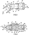
fig. 3 est une vue en perspective d'un tronçon de gaine, tel qu'illustré à lafig. 2 . - La
fig. 4 est une vue en coupe prise sensiblement selon les lignes IV-IV de lafig. 3 . - Les
fig. 5 à 7 sont des exemples de réalisation de l'ensemble de guidage conforme à l'invention. - Les
fig. 8 à 10 illustrent d'autres variantes de réalisation de la gaine conforme à l'invention.
- The
Fig. 1 is a schematic view of an example of use of a sheath according to the invention. - The
Fig. 2 is a partial view of an embodiment of a sheath according to the invention. - The
Fig. 3 is a perspective view of a duct section, as shown in FIG.Fig. 2 . - The
Fig. 4 is a sectional view taken substantially along the lines IV-IV of theFig. 3 . - The
Fig. 5 to 7 are exemplary embodiments of the guide assembly according to the invention. - The
Fig. 8 to 10 illustrate other embodiments of the sheath according to the invention.
Tel que cela ressort plus précisément de la
Le fil 2 est plein ou creux et présente une section par exemple circulaire ou autre. Le fil 2 est conditionné sous différentes formes, telles qu'en touret 51 , couronne, fût 52 ou en bobine 53 , comme illustré à la
Les
Par souci de clarté, il sera considéré qu'un support d'un type donné est adjacent ou voisin, selon l'un de ses côtés, d'un support d'un type différent, dit amont, en considération du sens d'avancement du fil et, selon son côté opposé, d'un support différent, dit aval.For the sake of clarity, it will be considered that a support of a given type is adjacent or adjacent, on one of its sides, a support of a different type, said upstream, in consideration of the direction of advancement wire and, according to its opposite side, a different support, said downstream.
Selon une autre caractéristique de l'invention, chaque support d'un type 101 , 102 est articulé avec chacun des supports voisins ou adjacents d'un type différent. Ainsi, mis à part les supports délimitant chaque extrémité de la gaine, chaque support d'un type donné, par exemple de premier type 101 , est articulé, d'une part, à l'aide de premiers moyens d'articulation 15 avec le support aval de second type 102 , selon au moins une direction d'articulation A et, d'autre part, à l'aide de deuxièmes moyens d'articulation 17 avec le support amont de second type 102 selon au moins une direction d'articulation B différente de la direction d'articulation A. De la même façon, chaque support d'un second type 102 est articulé d'une part, à l'aide des premiers moyens d'articulation 15 avec le support amont de premier type 101 selon au moins une direction d'articulation A et, d'autre part, à l'aide de deuxièmes moyens d'articulation 17 avec le support aval de premier type 101 selon au moins une direction d'articulation B.According to another characteristic of the invention, each support of a type 10 1 , 10 2 is articulated with each of the adjacent or adjacent supports of a different type. Thus, apart from the supports delimiting each end of the sheath, each support of a given type, for example of the first type 1 , is articulated, on the one hand, by means of first articulation means 15 with the second type of downstream support 10 2 , according to at least one articulation direction A and, secondly, using second articulation means 17 with the second type upstream support 10 2 in at least one direction articulation B different from the articulation direction A. In the same way, each support of a second type 2 2 is articulated on the one hand, with the aid of the first articulation means 15 with the first type of upstream support 10 1 according to at least one articulation direction A and, secondly, using second hinge means 17 with the first type of downstream support 10 1 according to at least one articulation direction B.
Avantageusement, les moyens d'articulation 15, 17 sont adaptés pour autoriser un mouvement des supports entre eux selon au moins deux directions d'articulation A, B perpendiculaires entre elles, de sorte que la gaine puisse suivre des courbures s'étendant dans des plans différents. Selon une caractéristique de réalisation, qui est illustrée plus précisément aux
Les supports de premier type 101 sont identiques aux supports de deuxième type 102 . Dans l'exemple considéré, les supports de premier type 101 sont décalés angulairement, selon l'axe de la gaine, de 90° par rapport aux supports de deuxième type 102 . Dans la suite de la description, les indices 1 et 2 des différents éléments constitutifs des supports seront rattachés, respectivement, aux supports de premier type 101 et aux supports de deuxième type 102. The supports of the first type 1 are identical to the supports of the second type 2 . In the example under consideration, the supports of the first type 1 are angularly offset, along the axis of the sheath, by 90 ° with respect to the supports of the second type 2 . In the following description, the
Chaque support 101 , 102 se présente sous la forme d'un corps tubulaire ou annulaire 201 , 202 délimitant, intérieurement, une cage 211 , 212 de montage pour un ensemble de guidage 111 , 112. Selon la variante de réalisation illustrée, chaque ensemble de guidage 111 , 112 comporte des organes de roulement 231 , 232 , montés en vis-à-vis pour délimiter le chemin de guidage 3 pour le fil 2. Chaque organe de roulement 231 , 232 est monté libre en rotation selon un axe 251 , 252 porté par le support 101 , 102. Dans l'exemple illustré aux
L'écartement des organes de roulement 231 , 232 , placés en vis-à-vis pour constituer un ensemble de guidage, est choisi de manière que le chemin de guidage 3 présente une section de passage supérieure au diamètre du fil. Cette section de passage est, avantageusement, choisie pour permettre le passage de fils de différents diamètres. Il doit être considéré que le fil 2 peut passer ainsi librement dans les parties de la gaine qui sont rectilignes ou droites, tandis que le fil 2 se trouve en contact avec les organes de roulement situés dans les parties de la gaine subissant une courbure.The spacing of the rolling members 23 1 , 23 2 , placed vis-à-vis to form a guide assembly, is chosen so that the
Chaque corps 201 , 202 se prolonge avantageusement, à l'opposé de la cage de montage 211 , 212 , par un tube de guidage 301 , 302 pour le fil, délimitant ainsi le chemin de guidage 3 pour le fil. Chaque tube de guidage 301 , 302 s'étend ainsi, entre l'ensemble de guidage 111 , 112 porté par ledit support correspondant et l'ensemble de guidage porté par le support aval. En d'autres termes, chaque tube de guidage 301 , 302 assure une continuité de guidage pour le fil entre deux ensembles de guidage voisins ou consécutifs 111 , 112 portés par deux supports de type différent. Chaque tube de guidage 301 , 302 possède, de préférence, une section longitudinale de forme tronconique qui se rétrécit en direction du support aval.Each body 20 1 , 20 2 is advantageously extended, opposite the mounting cage 21 1 , 21 2 , by a guide tube 30 1 , 30 2 for the wire, thus delimiting the
Chaque corps 201 , 202 est pourvu, également, de deux bras 321 , 322 , s'étendant parallèlement entre eux et de part et d'autre du tube de guidage 301 , 302 . Les deux bras 321 , 322 sont pourvus chacun d'un orifice de réception 331 , 332 pour respectivement un pivot 342 , 341 aménagés sur les corps 201 , 202 . Les deux orifices de réception 331 d'un support sont alignés et sont adaptés pour recevoir les deux pivots 342 d'un support aval permettant de former les premiers moyens d'articulation 15, tandis que les deux pivots 341 dudit support avec lesquels coopèrent les deux orifices 332 d'un support amont forment les deuxièmes moyens d'articulation 17. Bien entendu, la position des orifices de réception 331 , 332 sur les supports-peut être inversée avec la position des pivots 341 , 342 .Each body 20 1 , 20 2 is also provided with two arms 32 1 , 32 2 , extending parallel to each other and on either side of the guide tube 30 1 , 2 . The two arms 32 1 , 32 2 are each provided with a receiving orifice 33 1 , 33 2 for respectively a pivot 34 2 , 34 1 arranged on the bodies 20 1 , 20 2 . The two receiving orifices 33 1 of a support are aligned and are adapted to receive the two pivots 34 2 of a downstream support for forming the first articulation means 15 , while the two pivots 34 1 of said support with which cooperate the two orifices 33 2 of an upstream support form the second articulation means 17 . Of course, the position of the receiving orifices 33 1 , 33 2 on the supports-can be reversed with the position of the pivots 34 1 , 34 2 .
Avantageusement, il s'ensuit que chaque articulation A, B est située au voisinage d'un ensemble de guidage 111 , 112 . De préférence, chaque articulation A, B, voisine d'un ensemble de guidage, s'étend sensiblement parallèlement à l'axe d'au moins un organe de roulement appartenant audit ensemble de guidage. Ainsi, tel que cela ressort plus précisément de la
Selon une autre caractéristique de l'invention, la gaine 1 comporte des moyens de butée 40 adaptés pour limiter l'amplitude des premiers 15 et des deuxièmes 17 moyens d'articulation. Dans l'exemple illustré, les moyens de limitation 40 sont formés par le tube de guidage 301 , 302 d'un support, adapté pour venir en butée sur le corps d'un support voisin. Par exemple, le décalage d'alignement entre deux supports consécutifs peut être limité à une valeur de l'ordre de 30°.According to another characteristic of the invention, the
Il ressort de la description qui précède que la gaine 1 selon l'invention permet de guider le fil 2 lors de son avancement par l'intermédiaire, notamment, des organes de roulement 231, 232. La résistance à l'avancement du fil est due, uniquement, au frottement de l'organe de roulement sur son axe. Le guidage du fil 2 est ainsi assuré, même si la gaine subit des déplacements, notamment au niveau de son lieu d'utilisation, entraînant des changements de courbure dans différents plans. En effet, la mise en oeuvre des moyens d'articulation 15, 17 dans deux plans différents, alternés d'un support à l'autre autorise la gaine à suivre différentes conformations.It follows from the foregoing description that the
Selon une caractéristique préférée de réalisation, l'ensemble des supports 101, 102 peut être monté à l'intérieur d'une enveloppe de protection 50, comme illustré à la
Bien entendu, les moyens d'articulation 15, 17 peuvent être réalisés de manière différente d'une articulation à pivot. Chaque articulation à pivot peut être remplacée par une liaison élastique mettant en oeuvre un ou plusieurs ressorts ou éléments élastiques 55, comme illustré à la
De même, les supports 101, 102 peuvent être reliés entre eux par des moyens d'articulation, du type à rotule, tels qu'illustrés à la
Selon une autre variante de réalisation illustrée à la
Claims (7)
- A cable casing for the guidance of a wire (2) moving with a given direction of motion in a guidance path (3) created within the cable casing, said cable casing including:▪ supports of a first type (101) for first guidance assemblies (111) for the wire, with each including roller devices (231) mounted facing each other to form between them a part of the guidance path of the wire, and with each roller device being mounted to rotate freely on an axis (251) carried by a support,the cable casing being characterized in that it includes:▪ supports of a second type (102) for second guidance assemblies (112) for the wire, each including roller devices (232) mounted, firstly, facing each other to form between them a part of the guidance path of the wire, and secondly, each free to rotate on an axis (252) carried by the support, at least one of the axes of a roller device of the second guidance assemblies lying in a direction that is different from that of at least one axis of a roller device of the first guidance assemblies, the supports of the second guidance assemblies being positioned alternately with the supports of the first guidance assemblies; andfor each support of a type framed by supports upstream and downstream of another type, first articulation means (15) in at least one direction of articulation (A) between a support of one type with the upstream support of another type, and second articulation means (17) between the said support of one type with the downstream support of another type, in at least one direction of articulation that is different from the direction of articulation (B) between the said support and the upstream support, the first (15) and the second (17) articulation means being created by an articulation of the same type, such as of the pivot, swivel or elastic type,▪ the supports of first type (101) of the first guidance assemblies (111) being identical to the supports (102) of a second type of the second guidance assemblies (112), each support (101, 102) of the guidance assemblies being equipped with a guidance tube (301, 302) for the wire (2) lying between the guidance assembly carried by the said support and the guidance assembly carried by the support downstream or upstream.
- A guidance cable casing according to claim 1, characterized in that at least one of the axes of a roller device (231, 232) of the second guidance assemblies (112) lies in a direction perpendicular to that of at least one axis of a roller device of the first guidance assemblies (111), and in that the first (15) and second (17) articulation means have directions of articulation that are at least perpendicular to each other.
- A guidance cable casing according to claim 2, characterized in that the axes (251, 252) of the roller devices, forming part of a given guidance assembly, are parallel to each other.
- A guidance cable casing according to any of claims 1 to 3, characterized in that it includes travel-limiting means (40) that can be used to limit the amplitude of articulation of the first and the second articulation means.
- A guidance cable casing according to any of claims 1 to 4, characterized in that it includes a protective envelope (50) in which the supports (101, 102) of the first and second guidance assemblies are mounted.
- A guidance cable casing according to claim 5, characterized in that the protective envelope (50) includes a spring (51).
- A movement system (4) for a wire, using driving means (7), characterized in that it includes a guidance cable casing (1) for the wire (2), according to any of claims 1 to 6, positioned between the storage location of the wire and the place of use of the wire.
Priority Applications (1)
| Application Number | Priority Date | Filing Date | Title |
|---|---|---|---|
| PL06794491T PL1907308T3 (en) | 2005-07-22 | 2006-07-20 | Wire guiding sheath |
Applications Claiming Priority (2)
| Application Number | Priority Date | Filing Date | Title |
|---|---|---|---|
| FR0507810A FR2888825B1 (en) | 2005-07-22 | 2005-07-22 | SHEATH FOR GUIDING A WIRE |
| PCT/FR2006/050738 WO2007010171A2 (en) | 2005-07-22 | 2006-07-20 | Wire guiding sheath |
Publications (3)
| Publication Number | Publication Date |
|---|---|
| EP1907308A2 EP1907308A2 (en) | 2008-04-09 |
| EP1907308B1 EP1907308B1 (en) | 2010-06-23 |
| EP1907308B2 true EP1907308B2 (en) | 2017-05-03 |
Family
ID=36145911
Family Applications (1)
| Application Number | Title | Priority Date | Filing Date |
|---|---|---|---|
| EP06794491.8A Active EP1907308B2 (en) | 2005-07-22 | 2006-07-20 | Wire guiding sheath |
Country Status (7)
| Country | Link |
|---|---|
| US (1) | US20090200284A1 (en) |
| EP (1) | EP1907308B2 (en) |
| AT (1) | ATE471906T2 (en) |
| DE (1) | DE602006015060D1 (en) |
| FR (1) | FR2888825B1 (en) |
| PL (1) | PL1907308T3 (en) |
| WO (1) | WO2007010171A2 (en) |
Families Citing this family (30)
| Publication number | Priority date | Publication date | Assignee | Title |
|---|---|---|---|---|
| DE102007015946A1 (en) * | 2007-03-27 | 2008-10-02 | Sidergas Spa | Flexible guide for a welding wire |
| WO2009143917A1 (en) | 2008-05-27 | 2009-12-03 | Awds Technologies Srl | Wire guiding system |
| EP2174741B1 (en) | 2008-10-07 | 2012-06-20 | SIDERGAS SpA | Cover for welding wire container |
| US8674263B2 (en) | 2009-07-20 | 2014-03-18 | Awds Technologies Srl | Wire guiding liner, in particular a welding wire liner, with biasing means between articulated guiding bodies |
| US20110042355A1 (en) * | 2009-08-21 | 2011-02-24 | Carlo Gelmetti | Feeding system for a welding wire for a submerged welding process |
| US20110114617A1 (en) * | 2009-11-13 | 2011-05-19 | Carlo Gelmetti | Liner, in particular for welding wire |
| US8389901B1 (en) | 2010-05-27 | 2013-03-05 | Awds Technologies Srl | Welding wire guiding liner |
| US20120211479A1 (en) * | 2011-02-18 | 2012-08-23 | Illinois Tool Works Inc. | Self-cleaning welding wire conduit |
| EP2729274B1 (en) * | 2011-07-08 | 2015-09-16 | Elco Enterprises, Inc. | Wire guide module with a housing and rollers method of guiding a wire ; wire dispensing system with such module ; method of guiding wire from a wire source to a weld station |
| DE202011103453U1 (en) | 2011-07-18 | 2011-09-08 | Wilhelm Merkle | welder |
| DE202011103454U1 (en) | 2011-07-18 | 2011-09-28 | Wilhelm Merkle | welder |
| DE202011104120U1 (en) | 2011-08-05 | 2011-11-21 | Awds Technologies S.R.L. | Wire guide, in particular for the guidance of welding wire |
| US8882018B2 (en) | 2011-12-19 | 2014-11-11 | Sidergas Spa | Retainer for welding wire container and welding wire container with retainer |
| ITMI20121423A1 (en) * | 2012-08-09 | 2014-02-10 | Awds Technologies Srl | "SHEATH TO DRIVE AND TRANSPORT THE WIRE, IN PARTICULAR WIRE FOR WELDING" |
| EP2695696B1 (en) | 2012-08-09 | 2017-03-15 | AWDS Technologies SRL | Line for guiding a wire, in particular a welding wire, with at least two different types of bodies |
| CA2897611C (en) * | 2013-01-09 | 2018-10-30 | C6 Technologies As | A well intervention cable bending restriction for a rigid resilient rod-shaped intervention cable |
| US10294065B2 (en) | 2013-06-06 | 2019-05-21 | Sidergas Spa | Retainer for a welding wire container and welding wire container |
| US10343231B2 (en) | 2014-05-28 | 2019-07-09 | Awds Technologies Srl | Wire feeding system |
| DE102014108208A1 (en) * | 2014-06-11 | 2015-12-17 | Friedrich-Alexander-Universität Erlangen-Nürnberg | Wire guide element, wire winding machine with such, method for introducing wire and method for feeding wire |
| DE102014009390A1 (en) * | 2014-06-25 | 2015-12-31 | Fraunhofer-Gesellschaft zur Förderung der angewandten Forschung e.V. | Device for spatially assisted guidance of a flexurally elastic strand material and its use in an arrangement for producing a three-dimensional object by way of a generative manufacturing process |
| US10010962B1 (en) | 2014-09-09 | 2018-07-03 | Awds Technologies Srl | Module and system for controlling and recording welding data, and welding wire feeder |
| US10350696B2 (en) | 2015-04-06 | 2019-07-16 | Awds Technologies Srl | Wire feed system and method of controlling feed of welding wire |
| US9975728B2 (en) | 2015-09-10 | 2018-05-22 | Sidergas Spa | Wire container lid, wire container and wire feeding system |
| US10500670B2 (en) | 2015-11-06 | 2019-12-10 | Elco Enterprises, Inc. | Flexible wire guide system |
| GB2558815A (en) | 2015-11-18 | 2018-07-18 | Halliburton Energy Services Inc | Segmented bend-limiter for slickline rope sockets and cable-heads |
| US9950857B1 (en) | 2016-10-17 | 2018-04-24 | Sidergas Spa | Welding wire container |
| US11174121B2 (en) | 2020-01-20 | 2021-11-16 | Awds Technologies Srl | Device for imparting a torsional force onto a wire |
| US11278981B2 (en) | 2020-01-20 | 2022-03-22 | Awds Technologies Srl | Device for imparting a torsional force onto a wire |
| KR102540380B1 (en) * | 2021-10-15 | 2023-06-05 | 황지윤 | Liner feeding system with adjustable rotation angle |
| CN115352959A (en) * | 2022-08-19 | 2022-11-18 | 北京华电瑞通电力工程技术有限公司 | High-efficient conveyor of electric power engineering construction |
Citations (9)
| Publication number | Priority date | Publication date | Assignee | Title |
|---|---|---|---|---|
| US1258233A (en) † | 1916-04-10 | 1918-03-05 | Clare P Mccaskey | Flexible shaft. |
| US1602691A (en) † | 1924-05-08 | 1926-10-12 | Alfred S Mccaskey | Flexible shaft |
| US2457910A (en) † | 1946-02-02 | 1949-01-04 | W L Maxson Corp | Flexible cable |
| US3274850A (en) † | 1964-11-04 | 1966-09-27 | Nazarene F Tascio | Flexible push-pull control cable |
| DE2525938A1 (en) † | 1975-06-11 | 1976-12-16 | Messer Griesheim Gmbh | Submerged arc welding internal seam in pipe mfr. - using flexible rows of roller guides to feed electrode wire to burner nozzles |
| JPH09191520A (en) † | 1996-01-05 | 1997-07-22 | Hitachi Cable Ltd | Cable guide with roller |
| US5994659A (en) † | 1996-06-20 | 1999-11-30 | General Electric Company | Method and apparatus for welding with preheated filler material |
| US6729606B1 (en) † | 1999-08-10 | 2004-05-04 | I.C.M. Group | Device for guiding at least a flexible elongated element such as a cable or the like, with substantially closed contour |
| WO2006091075A1 (en) † | 2005-01-17 | 2006-08-31 | Marcel Francesco De Keizer | Wire guide |
Family Cites Families (6)
| Publication number | Priority date | Publication date | Assignee | Title |
|---|---|---|---|---|
| US1898060A (en) * | 1919-09-11 | 1933-02-21 | Gen Electric | Method and apparatus for electric arc welding |
| DE449929C (en) * | 1924-08-09 | 1928-03-28 | Siemens Schuckertwerke Akt Ges | Arc welding machine |
| US2694130A (en) * | 1952-08-28 | 1954-11-09 | Posy A Howard | Arc welding wire guide |
| DE2222493A1 (en) * | 1972-05-08 | 1973-11-22 | Erich Geiger | BALL REVERSE WITH BALL REVERSING NUT |
| US4278238A (en) * | 1980-01-21 | 1981-07-14 | Western Electric Company, Inc. | Cable feeding tool |
| US5215338A (en) * | 1985-04-09 | 1993-06-01 | Tsubakimoto Chain Co. | Flexible supporting sheath for cables and the like |
-
2005
- 2005-07-22 FR FR0507810A patent/FR2888825B1/en active Active
-
2006
- 2006-07-20 EP EP06794491.8A patent/EP1907308B2/en active Active
- 2006-07-20 AT AT06794491T patent/ATE471906T2/en active
- 2006-07-20 DE DE602006015060T patent/DE602006015060D1/en active Active
- 2006-07-20 PL PL06794491T patent/PL1907308T3/en unknown
- 2006-07-20 WO PCT/FR2006/050738 patent/WO2007010171A2/en active Application Filing
- 2006-07-20 US US11/989,120 patent/US20090200284A1/en not_active Abandoned
Patent Citations (9)
| Publication number | Priority date | Publication date | Assignee | Title |
|---|---|---|---|---|
| US1258233A (en) † | 1916-04-10 | 1918-03-05 | Clare P Mccaskey | Flexible shaft. |
| US1602691A (en) † | 1924-05-08 | 1926-10-12 | Alfred S Mccaskey | Flexible shaft |
| US2457910A (en) † | 1946-02-02 | 1949-01-04 | W L Maxson Corp | Flexible cable |
| US3274850A (en) † | 1964-11-04 | 1966-09-27 | Nazarene F Tascio | Flexible push-pull control cable |
| DE2525938A1 (en) † | 1975-06-11 | 1976-12-16 | Messer Griesheim Gmbh | Submerged arc welding internal seam in pipe mfr. - using flexible rows of roller guides to feed electrode wire to burner nozzles |
| JPH09191520A (en) † | 1996-01-05 | 1997-07-22 | Hitachi Cable Ltd | Cable guide with roller |
| US5994659A (en) † | 1996-06-20 | 1999-11-30 | General Electric Company | Method and apparatus for welding with preheated filler material |
| US6729606B1 (en) † | 1999-08-10 | 2004-05-04 | I.C.M. Group | Device for guiding at least a flexible elongated element such as a cable or the like, with substantially closed contour |
| WO2006091075A1 (en) † | 2005-01-17 | 2006-08-31 | Marcel Francesco De Keizer | Wire guide |
Also Published As
| Publication number | Publication date |
|---|---|
| ATE471906T2 (en) | 2010-07-15 |
| EP1907308B1 (en) | 2010-06-23 |
| FR2888825B1 (en) | 2007-10-19 |
| DE602006015060D1 (en) | 2010-08-05 |
| WO2007010171A2 (en) | 2007-01-25 |
| FR2888825A1 (en) | 2007-01-26 |
| EP1907308A2 (en) | 2008-04-09 |
| US20090200284A1 (en) | 2009-08-13 |
| WO2007010171A3 (en) | 2007-03-15 |
| PL1907308T3 (en) | 2011-06-30 |
Similar Documents
| Publication | Publication Date | Title |
|---|---|---|
| EP1907308B2 (en) | Wire guiding sheath | |
| EP2125301B1 (en) | Compact manipulation robot | |
| EP2007541B1 (en) | Orbital carrier comprising at least two components in the form of segments of a circle able to be connected together; device for butt-welding pipes to form a pipeline comprising such an orbital carrier | |
| EP2184240B1 (en) | Device for moving on an endless belt with adaptable trajectory | |
| EP1854591B1 (en) | Parallel robot | |
| EP1973820B1 (en) | Pneumatic conveyor | |
| EP1278984B1 (en) | Self-propelled carriage capable of moving in a cylindrical tunnel | |
| FR3101058A1 (en) | Electrically driven steering system for one vehicle | |
| FR2900139A1 (en) | SUPPORT STATION FOR A BAND CONVEYOR AND CONVEYOR HAVING THE SAME | |
| EP2468631B1 (en) | Self-regulated self-motorised hinge and hinged assembly | |
| WO2018091814A1 (en) | Machine and method for simultaneously laying cables in a helix on the outer surface of a unit element of a fluid transport duct | |
| FR3015320A1 (en) | ELECTRICAL ARC WELDING MACHINE | |
| EP1409907A1 (en) | Tool-bearing carriage, in particular mobile in a pipe | |
| WO2010012897A1 (en) | Method and installation for constructing a layer of armour strips | |
| FR3044955A1 (en) | ||
| WO2018115787A1 (en) | The method and installation for regulating the pitch of the turns of a metal carcass | |
| FR2743932A1 (en) | WIRE HARNESS COVERING TOOL | |
| FR3020000A1 (en) | FLOATING CONNECTION FOR TOOL | |
| EP2941553A1 (en) | Motor vehicle exhaust line comprising an improved ball-and-socket joint | |
| EP3019328B1 (en) | Guide wheel for assemblies for fitting layers of armor wires, and associated mounting method | |
| WO2020115064A1 (en) | Transfer device for maintaining an electrical or optical connection | |
| WO2009004397A1 (en) | Roller for a travelling belt conveyor arranged to produce spontaneous centring of the belt on its guide path | |
| FR3140574A1 (en) | FIBER APPLICATION MACHINE WITH SPECIAL FIBER DELIVERY MEANS | |
| EP1661779A1 (en) | Vehicle washing unit | |
| FR2958277A1 (en) | Storage device for storing flexible device i.e. hose, has intermediate storage device in which hose is accumulated without displacement, where hose is stored in intermediate storing device from helical input area to helical output area |
Legal Events
| Date | Code | Title | Description |
|---|---|---|---|
| PUAI | Public reference made under article 153(3) epc to a published international application that has entered the european phase |
Free format text: ORIGINAL CODE: 0009012 |
|
| 17P | Request for examination filed |
Effective date: 20080206 |
|
| AK | Designated contracting states |
Kind code of ref document: A2 Designated state(s): AT BE BG CH CY CZ DE DK EE ES FI FR GB GR HU IE IS IT LI LT LU LV MC NL PL PT RO SE SI SK TR |
|
| 17Q | First examination report despatched |
Effective date: 20080428 |
|
| GRAP | Despatch of communication of intention to grant a patent |
Free format text: ORIGINAL CODE: EPIDOSNIGR1 |
|
| GRAS | Grant fee paid |
Free format text: ORIGINAL CODE: EPIDOSNIGR3 |
|
| GRAA | (expected) grant |
Free format text: ORIGINAL CODE: 0009210 |
|
| AK | Designated contracting states |
Kind code of ref document: B1 Designated state(s): AT BE BG CH CY CZ DE DK EE ES FI FR GB GR HU IE IS IT LI LT LU LV MC NL PL PT RO SE SI SK TR |
|
| REG | Reference to a national code |
Ref country code: CH Ref legal event code: EP |
|
| REG | Reference to a national code |
Ref country code: IE Ref legal event code: FG4D Free format text: LANGUAGE OF EP DOCUMENT: FRENCH |
|
| REF | Corresponds to: |
Ref document number: 602006015060 Country of ref document: DE Date of ref document: 20100805 Kind code of ref document: P |
|
| REG | Reference to a national code |
Ref country code: SE Ref legal event code: TRGR |
|
| REG | Reference to a national code |
Ref country code: CH Ref legal event code: NV Representative=s name: BOVARD AG PATENTANWAELTE |
|
| REG | Reference to a national code |
Ref country code: NL Ref legal event code: T3 |
|
| PG25 | Lapsed in a contracting state [announced via postgrant information from national office to epo] |
Ref country code: LT Free format text: LAPSE BECAUSE OF FAILURE TO SUBMIT A TRANSLATION OF THE DESCRIPTION OR TO PAY THE FEE WITHIN THE PRESCRIBED TIME-LIMIT Effective date: 20100623 |
|
| PGFP | Annual fee paid to national office [announced via postgrant information from national office to epo] |
Ref country code: MC Payment date: 20100920 Year of fee payment: 5 |
|
| LTIE | Lt: invalidation of european patent or patent extension |
Effective date: 20100623 |
|
| PG25 | Lapsed in a contracting state [announced via postgrant information from national office to epo] |
Ref country code: SI Free format text: LAPSE BECAUSE OF FAILURE TO SUBMIT A TRANSLATION OF THE DESCRIPTION OR TO PAY THE FEE WITHIN THE PRESCRIBED TIME-LIMIT Effective date: 20100623 Ref country code: LV Free format text: LAPSE BECAUSE OF FAILURE TO SUBMIT A TRANSLATION OF THE DESCRIPTION OR TO PAY THE FEE WITHIN THE PRESCRIBED TIME-LIMIT Effective date: 20100623 Ref country code: FI Free format text: LAPSE BECAUSE OF FAILURE TO SUBMIT A TRANSLATION OF THE DESCRIPTION OR TO PAY THE FEE WITHIN THE PRESCRIBED TIME-LIMIT Effective date: 20100623 |
|
| PGFP | Annual fee paid to national office [announced via postgrant information from national office to epo] |
Ref country code: LU Payment date: 20100823 Year of fee payment: 5 |
|
| PG25 | Lapsed in a contracting state [announced via postgrant information from national office to epo] |
Ref country code: GR Free format text: LAPSE BECAUSE OF FAILURE TO SUBMIT A TRANSLATION OF THE DESCRIPTION OR TO PAY THE FEE WITHIN THE PRESCRIBED TIME-LIMIT Effective date: 20100924 |
|
| PG25 | Lapsed in a contracting state [announced via postgrant information from national office to epo] |
Ref country code: EE Free format text: LAPSE BECAUSE OF FAILURE TO SUBMIT A TRANSLATION OF THE DESCRIPTION OR TO PAY THE FEE WITHIN THE PRESCRIBED TIME-LIMIT Effective date: 20100623 |
|
| REG | Reference to a national code |
Ref country code: IE Ref legal event code: FD4D |
|
| PG25 | Lapsed in a contracting state [announced via postgrant information from national office to epo] |
Ref country code: CY Free format text: LAPSE BECAUSE OF FAILURE TO SUBMIT A TRANSLATION OF THE DESCRIPTION OR TO PAY THE FEE WITHIN THE PRESCRIBED TIME-LIMIT Effective date: 20100623 Ref country code: PT Free format text: LAPSE BECAUSE OF FAILURE TO SUBMIT A TRANSLATION OF THE DESCRIPTION OR TO PAY THE FEE WITHIN THE PRESCRIBED TIME-LIMIT Effective date: 20101025 Ref country code: IS Free format text: LAPSE BECAUSE OF FAILURE TO SUBMIT A TRANSLATION OF THE DESCRIPTION OR TO PAY THE FEE WITHIN THE PRESCRIBED TIME-LIMIT Effective date: 20101023 Ref country code: RO Free format text: LAPSE BECAUSE OF FAILURE TO SUBMIT A TRANSLATION OF THE DESCRIPTION OR TO PAY THE FEE WITHIN THE PRESCRIBED TIME-LIMIT Effective date: 20100623 Ref country code: SK Free format text: LAPSE BECAUSE OF FAILURE TO SUBMIT A TRANSLATION OF THE DESCRIPTION OR TO PAY THE FEE WITHIN THE PRESCRIBED TIME-LIMIT Effective date: 20100623 |
|
| PLBI | Opposition filed |
Free format text: ORIGINAL CODE: 0009260 |
|
| PLAZ | Examination of admissibility of opposition: despatch of communication + time limit |
Free format text: ORIGINAL CODE: EPIDOSNOPE2 |
|
| REG | Reference to a national code |
Ref country code: CH Ref legal event code: PFA Owner name: I.A.B. DEVELOPPEMENTS Free format text: I.A.B. DEVELOPPEMENTS#12, RUE THUROT#21000 DIJON (FR) -TRANSFER TO- I.A.B. DEVELOPPEMENTS#12, RUE THUROT#21000 DIJON (FR) |
|
| 26 | Opposition filed |
Opponent name: SIDERGAS SPA Effective date: 20110302 |
|
| PLBA | Examination of admissibility of opposition: reply received |
Free format text: ORIGINAL CODE: EPIDOSNOPE4 |
|
| PLAX | Notice of opposition and request to file observation + time limit sent |
Free format text: ORIGINAL CODE: EPIDOSNOBS2 |
|
| PG25 | Lapsed in a contracting state [announced via postgrant information from national office to epo] |
Ref country code: DK Free format text: LAPSE BECAUSE OF FAILURE TO SUBMIT A TRANSLATION OF THE DESCRIPTION OR TO PAY THE FEE WITHIN THE PRESCRIBED TIME-LIMIT Effective date: 20100623 Ref country code: IE Free format text: LAPSE BECAUSE OF FAILURE TO SUBMIT A TRANSLATION OF THE DESCRIPTION OR TO PAY THE FEE WITHIN THE PRESCRIBED TIME-LIMIT Effective date: 20100623 |
|
| REG | Reference to a national code |
Ref country code: DE Ref legal event code: R026 Ref document number: 602006015060 Country of ref document: DE Effective date: 20110302 |
|
| REG | Reference to a national code |
Ref country code: PL Ref legal event code: T3 |
|
| PLBB | Reply of patent proprietor to notice(s) of opposition received |
Free format text: ORIGINAL CODE: EPIDOSNOBS3 |
|
| PGFP | Annual fee paid to national office [announced via postgrant information from national office to epo] |
Ref country code: PL Payment date: 20110720 Year of fee payment: 6 Ref country code: GB Payment date: 20110824 Year of fee payment: 6 |
|
| PGFP | Annual fee paid to national office [announced via postgrant information from national office to epo] |
Ref country code: BE Payment date: 20110826 Year of fee payment: 6 |
|
| PG25 | Lapsed in a contracting state [announced via postgrant information from national office to epo] |
Ref country code: MC Free format text: LAPSE BECAUSE OF NON-PAYMENT OF DUE FEES Effective date: 20110731 |
|
| APBM | Appeal reference recorded |
Free format text: ORIGINAL CODE: EPIDOSNREFNO |
|
| APBP | Date of receipt of notice of appeal recorded |
Free format text: ORIGINAL CODE: EPIDOSNNOA2O |
|
| APAH | Appeal reference modified |
Free format text: ORIGINAL CODE: EPIDOSCREFNO |
|
| PG25 | Lapsed in a contracting state [announced via postgrant information from national office to epo] |
Ref country code: HU Free format text: LAPSE BECAUSE OF FAILURE TO SUBMIT A TRANSLATION OF THE DESCRIPTION OR TO PAY THE FEE WITHIN THE PRESCRIBED TIME-LIMIT Effective date: 20101224 Ref country code: BG Free format text: LAPSE BECAUSE OF FAILURE TO SUBMIT A TRANSLATION OF THE DESCRIPTION OR TO PAY THE FEE WITHIN THE PRESCRIBED TIME-LIMIT Effective date: 20100623 |
|
| PG25 | Lapsed in a contracting state [announced via postgrant information from national office to epo] |
Ref country code: TR Free format text: LAPSE BECAUSE OF FAILURE TO SUBMIT A TRANSLATION OF THE DESCRIPTION OR TO PAY THE FEE WITHIN THE PRESCRIBED TIME-LIMIT Effective date: 20100623 |
|
| APBQ | Date of receipt of statement of grounds of appeal recorded |
Free format text: ORIGINAL CODE: EPIDOSNNOA3O |
|
| BERE | Be: lapsed |
Owner name: I.A.B. DEVELOPPEMENTS Effective date: 20120731 |
|
| GBPC | Gb: european patent ceased through non-payment of renewal fee |
Effective date: 20120720 |
|
| PG25 | Lapsed in a contracting state [announced via postgrant information from national office to epo] |
Ref country code: GB Free format text: LAPSE BECAUSE OF NON-PAYMENT OF DUE FEES Effective date: 20120720 |
|
| PG25 | Lapsed in a contracting state [announced via postgrant information from national office to epo] |
Ref country code: BE Free format text: LAPSE BECAUSE OF NON-PAYMENT OF DUE FEES Effective date: 20120731 Ref country code: LU Free format text: LAPSE BECAUSE OF NON-PAYMENT OF DUE FEES Effective date: 20110720 |
|
| PG25 | Lapsed in a contracting state [announced via postgrant information from national office to epo] |
Ref country code: BG Free format text: LAPSE BECAUSE OF FAILURE TO SUBMIT A TRANSLATION OF THE DESCRIPTION OR TO PAY THE FEE WITHIN THE PRESCRIBED TIME-LIMIT Effective date: 20100923 |
|
| PG25 | Lapsed in a contracting state [announced via postgrant information from national office to epo] |
Ref country code: ES Free format text: LAPSE BECAUSE OF FAILURE TO SUBMIT A TRANSLATION OF THE DESCRIPTION OR TO PAY THE FEE WITHIN THE PRESCRIBED TIME-LIMIT Effective date: 20101004 |
|
| REG | Reference to a national code |
Ref country code: PL Ref legal event code: LAPE |
|
| PG25 | Lapsed in a contracting state [announced via postgrant information from national office to epo] |
Ref country code: PL Free format text: LAPSE BECAUSE OF NON-PAYMENT OF DUE FEES Effective date: 20120720 |
|
| APBU | Appeal procedure closed |
Free format text: ORIGINAL CODE: EPIDOSNNOA9O |
|
| REG | Reference to a national code |
Ref country code: FR Ref legal event code: PLFP Year of fee payment: 11 |
|
| PUAH | Patent maintained in amended form |
Free format text: ORIGINAL CODE: 0009272 |
|
| STAA | Information on the status of an ep patent application or granted ep patent |
Free format text: STATUS: PATENT MAINTAINED AS AMENDED |
|
| 27A | Patent maintained in amended form |
Effective date: 20170503 |
|
| AK | Designated contracting states |
Kind code of ref document: B2 Designated state(s): AT BE BG CH CY CZ DE DK EE ES FI FR GB GR HU IE IS IT LI LT LU LV MC NL PL PT RO SE SI SK TR |
|
| REG | Reference to a national code |
Ref country code: DE Ref legal event code: R102 Ref document number: 602006015060 Country of ref document: DE |
|
| REG | Reference to a national code |
Ref country code: CH Ref legal event code: AELC |
|
| REG | Reference to a national code |
Ref country code: FR Ref legal event code: PLFP Year of fee payment: 12 |
|
| PGFP | Annual fee paid to national office [announced via postgrant information from national office to epo] |
Ref country code: CZ Payment date: 20170601 Year of fee payment: 12 |
|
| REG | Reference to a national code |
Ref country code: SE Ref legal event code: RPEO |
|
| REG | Reference to a national code |
Ref country code: NL Ref legal event code: FP |
|
| PG25 | Lapsed in a contracting state [announced via postgrant information from national office to epo] |
Ref country code: CZ Free format text: LAPSE BECAUSE OF FAILURE TO SUBMIT A TRANSLATION OF THE DESCRIPTION OR TO PAY THE FEE WITHIN THE PRESCRIBED TIME-LIMIT Effective date: 20100623 |
|
| REG | Reference to a national code |
Ref country code: FR Ref legal event code: PLFP Year of fee payment: 13 |
|
| REG | Reference to a national code |
Ref country code: AT Ref legal event code: UEP Ref document number: 471906 Country of ref document: AT Kind code of ref document: T Effective date: 20170503 |
|
| REG | Reference to a national code |
Ref country code: DE Ref legal event code: R082 Ref document number: 602006015060 Country of ref document: DE Representative=s name: CBDL PATENTANWAELTE GBR, DE |
|
| PGFP | Annual fee paid to national office [announced via postgrant information from national office to epo] |
Ref country code: NL Payment date: 20230622 Year of fee payment: 18 Ref country code: FR Payment date: 20230419 Year of fee payment: 18 |
|
| PGFP | Annual fee paid to national office [announced via postgrant information from national office to epo] |
Ref country code: IT Payment date: 20230707 Year of fee payment: 18 Ref country code: CH Payment date: 20230802 Year of fee payment: 18 Ref country code: AT Payment date: 20230621 Year of fee payment: 18 |
|
| PGFP | Annual fee paid to national office [announced via postgrant information from national office to epo] |
Ref country code: SE Payment date: 20230721 Year of fee payment: 18 Ref country code: DE Payment date: 20230712 Year of fee payment: 18 |