EP1910060B1 - Nanostructured article and method of making the same - Google Patents
Nanostructured article and method of making the same Download PDFInfo
- Publication number
- EP1910060B1 EP1910060B1 EP06787189.7A EP06787189A EP1910060B1 EP 1910060 B1 EP1910060 B1 EP 1910060B1 EP 06787189 A EP06787189 A EP 06787189A EP 1910060 B1 EP1910060 B1 EP 1910060B1
- Authority
- EP
- European Patent Office
- Prior art keywords
- tool
- film
- thermoplastic polymer
- continuous layer
- nanofibrils
- Prior art date
- Legal status (The legal status is an assumption and is not a legal conclusion. Google has not performed a legal analysis and makes no representation as to the accuracy of the status listed.)
- Not-in-force
Links
Images

Classifications
-
- B—PERFORMING OPERATIONS; TRANSPORTING
- B29—WORKING OF PLASTICS; WORKING OF SUBSTANCES IN A PLASTIC STATE IN GENERAL
- B29C—SHAPING OR JOINING OF PLASTICS; SHAPING OF MATERIAL IN A PLASTIC STATE, NOT OTHERWISE PROVIDED FOR; AFTER-TREATMENT OF THE SHAPED PRODUCTS, e.g. REPAIRING
- B29C59/00—Surface shaping of articles, e.g. embossing; Apparatus therefor
- B29C59/02—Surface shaping of articles, e.g. embossing; Apparatus therefor by mechanical means, e.g. pressing
- B29C59/022—Surface shaping of articles, e.g. embossing; Apparatus therefor by mechanical means, e.g. pressing characterised by the disposition or the configuration, e.g. dimensions, of the embossments or the shaping tools therefor
- B29C59/025—Fibrous surfaces with piles or similar fibres substantially perpendicular to the surface
-
- B—PERFORMING OPERATIONS; TRANSPORTING
- B29—WORKING OF PLASTICS; WORKING OF SUBSTANCES IN A PLASTIC STATE IN GENERAL
- B29C—SHAPING OR JOINING OF PLASTICS; SHAPING OF MATERIAL IN A PLASTIC STATE, NOT OTHERWISE PROVIDED FOR; AFTER-TREATMENT OF THE SHAPED PRODUCTS, e.g. REPAIRING
- B29C59/00—Surface shaping of articles, e.g. embossing; Apparatus therefor
- B29C59/02—Surface shaping of articles, e.g. embossing; Apparatus therefor by mechanical means, e.g. pressing
-
- B—PERFORMING OPERATIONS; TRANSPORTING
- B29—WORKING OF PLASTICS; WORKING OF SUBSTANCES IN A PLASTIC STATE IN GENERAL
- B29C—SHAPING OR JOINING OF PLASTICS; SHAPING OF MATERIAL IN A PLASTIC STATE, NOT OTHERWISE PROVIDED FOR; AFTER-TREATMENT OF THE SHAPED PRODUCTS, e.g. REPAIRING
- B29C33/00—Moulds or cores; Details thereof or accessories therefor
- B29C33/56—Coatings, e.g. enameled or galvanised; Releasing, lubricating or separating agents
- B29C33/60—Releasing, lubricating or separating agents
-
- B—PERFORMING OPERATIONS; TRANSPORTING
- B29—WORKING OF PLASTICS; WORKING OF SUBSTANCES IN A PLASTIC STATE IN GENERAL
- B29C—SHAPING OR JOINING OF PLASTICS; SHAPING OF MATERIAL IN A PLASTIC STATE, NOT OTHERWISE PROVIDED FOR; AFTER-TREATMENT OF THE SHAPED PRODUCTS, e.g. REPAIRING
- B29C59/00—Surface shaping of articles, e.g. embossing; Apparatus therefor
- B29C59/02—Surface shaping of articles, e.g. embossing; Apparatus therefor by mechanical means, e.g. pressing
- B29C59/04—Surface shaping of articles, e.g. embossing; Apparatus therefor by mechanical means, e.g. pressing using rollers or endless belts
-
- B—PERFORMING OPERATIONS; TRANSPORTING
- B82—NANOTECHNOLOGY
- B82Y—SPECIFIC USES OR APPLICATIONS OF NANOSTRUCTURES; MEASUREMENT OR ANALYSIS OF NANOSTRUCTURES; MANUFACTURE OR TREATMENT OF NANOSTRUCTURES
- B82Y30/00—Nanotechnology for materials or surface science, e.g. nanocomposites
-
- C—CHEMISTRY; METALLURGY
- C10—PETROLEUM, GAS OR COKE INDUSTRIES; TECHNICAL GASES CONTAINING CARBON MONOXIDE; FUELS; LUBRICANTS; PEAT
- C10M—LUBRICATING COMPOSITIONS; USE OF CHEMICAL SUBSTANCES EITHER ALONE OR AS LUBRICATING INGREDIENTS IN A LUBRICATING COMPOSITION
- C10M133/00—Lubricating compositions characterised by the additive being an organic non-macromolecular compound containing nitrogen
- C10M133/02—Lubricating compositions characterised by the additive being an organic non-macromolecular compound containing nitrogen having a carbon chain of less than 30 atoms
- C10M133/38—Heterocyclic nitrogen compounds
- C10M133/44—Five-membered ring containing nitrogen and carbon only
-
- C—CHEMISTRY; METALLURGY
- C25—ELECTROLYTIC OR ELECTROPHORETIC PROCESSES; APPARATUS THEREFOR
- C25D—PROCESSES FOR THE ELECTROLYTIC OR ELECTROPHORETIC PRODUCTION OF COATINGS; ELECTROFORMING; APPARATUS THEREFOR
- C25D11/00—Electrolytic coating by surface reaction, i.e. forming conversion layers
- C25D11/02—Anodisation
- C25D11/04—Anodisation of aluminium or alloys based thereon
- C25D11/18—After-treatment, e.g. pore-sealing
-
- B—PERFORMING OPERATIONS; TRANSPORTING
- B29—WORKING OF PLASTICS; WORKING OF SUBSTANCES IN A PLASTIC STATE IN GENERAL
- B29C—SHAPING OR JOINING OF PLASTICS; SHAPING OF MATERIAL IN A PLASTIC STATE, NOT OTHERWISE PROVIDED FOR; AFTER-TREATMENT OF THE SHAPED PRODUCTS, e.g. REPAIRING
- B29C59/00—Surface shaping of articles, e.g. embossing; Apparatus therefor
- B29C59/02—Surface shaping of articles, e.g. embossing; Apparatus therefor by mechanical means, e.g. pressing
- B29C59/022—Surface shaping of articles, e.g. embossing; Apparatus therefor by mechanical means, e.g. pressing characterised by the disposition or the configuration, e.g. dimensions, of the embossments or the shaping tools therefor
- B29C2059/023—Microembossing
-
- B—PERFORMING OPERATIONS; TRANSPORTING
- B29—WORKING OF PLASTICS; WORKING OF SUBSTANCES IN A PLASTIC STATE IN GENERAL
- B29C—SHAPING OR JOINING OF PLASTICS; SHAPING OF MATERIAL IN A PLASTIC STATE, NOT OTHERWISE PROVIDED FOR; AFTER-TREATMENT OF THE SHAPED PRODUCTS, e.g. REPAIRING
- B29C37/00—Component parts, details, accessories or auxiliary operations, not covered by group B29C33/00 or B29C35/00
- B29C37/0053—Moulding articles characterised by the shape of the surface, e.g. ribs, high polish
-
- C—CHEMISTRY; METALLURGY
- C25—ELECTROLYTIC OR ELECTROPHORETIC PROCESSES; APPARATUS THEREFOR
- C25D—PROCESSES FOR THE ELECTROLYTIC OR ELECTROPHORETIC PRODUCTION OF COATINGS; ELECTROFORMING; APPARATUS THEREFOR
- C25D1/00—Electroforming
- C25D1/04—Wires; Strips; Foils
-
- Y—GENERAL TAGGING OF NEW TECHNOLOGICAL DEVELOPMENTS; GENERAL TAGGING OF CROSS-SECTIONAL TECHNOLOGIES SPANNING OVER SEVERAL SECTIONS OF THE IPC; TECHNICAL SUBJECTS COVERED BY FORMER USPC CROSS-REFERENCE ART COLLECTIONS [XRACs] AND DIGESTS
- Y10—TECHNICAL SUBJECTS COVERED BY FORMER USPC
- Y10T—TECHNICAL SUBJECTS COVERED BY FORMER US CLASSIFICATION
- Y10T428/00—Stock material or miscellaneous articles
- Y10T428/24—Structurally defined web or sheet [e.g., overall dimension, etc.]
- Y10T428/24942—Structurally defined web or sheet [e.g., overall dimension, etc.] including components having same physical characteristic in differing degree
- Y10T428/2495—Thickness [relative or absolute]
-
- Y—GENERAL TAGGING OF NEW TECHNOLOGICAL DEVELOPMENTS; GENERAL TAGGING OF CROSS-SECTIONAL TECHNOLOGIES SPANNING OVER SEVERAL SECTIONS OF THE IPC; TECHNICAL SUBJECTS COVERED BY FORMER USPC CROSS-REFERENCE ART COLLECTIONS [XRACs] AND DIGESTS
- Y10—TECHNICAL SUBJECTS COVERED BY FORMER USPC
- Y10T—TECHNICAL SUBJECTS COVERED BY FORMER US CLASSIFICATION
- Y10T428/00—Stock material or miscellaneous articles
- Y10T428/249921—Web or sheet containing structurally defined element or component
- Y10T428/249924—Noninterengaged fiber-containing paper-free web or sheet which is not of specified porosity
-
- Y—GENERAL TAGGING OF NEW TECHNOLOGICAL DEVELOPMENTS; GENERAL TAGGING OF CROSS-SECTIONAL TECHNOLOGIES SPANNING OVER SEVERAL SECTIONS OF THE IPC; TECHNICAL SUBJECTS COVERED BY FORMER USPC CROSS-REFERENCE ART COLLECTIONS [XRACs] AND DIGESTS
- Y10—TECHNICAL SUBJECTS COVERED BY FORMER USPC
- Y10T—TECHNICAL SUBJECTS COVERED BY FORMER US CLASSIFICATION
- Y10T442/00—Fabric [woven, knitted, or nonwoven textile or cloth, etc.]
- Y10T442/60—Nonwoven fabric [i.e., nonwoven strand or fiber material]
- Y10T442/608—Including strand or fiber material which is of specific structural definition
Definitions
- surface nanostructures have attracted much attention because they provide unique properties for many potential applications. For example, in some cases surface nanostructure can dramatically change the apparent surface energy, which is particularly useful in articles wherein fluid control would be either essential or advantageous.
- DE 100 64 520 A1 desribes a process for creating surface structures which display a self-cleaning effect which comprises the steps of generating of a micro- or a nano-structure on the surface of a carrier by anodic oxidation and transferring of the surface structure of the carrier onto the substrate to be structured.
- the present invention provides a method of making nanostructured polymeric film comprising:
- Methods according to the present invention are useful for preparing exotic surface structures that are useful, for example, for modifying wetting characteristics (for example, increasing or decreasing wetting) of fluids on polymeric surfaces.
- aluminum refers to aluminum and alloys of aluminum in which a majority by weight of the alloy is aluminum.
- other metals which may be present in such aluminum alloys are silicon, magnesium, bismuth, copper, nickel, zinc, chromium, lead, iron, titanium, and manganese.
- the tool has a porous surface (characterized by a network of pores) that is formed directly or indirectly by anodizing aluminum.
- a porous surface characterized by a network of pores
- the porous surface may be formed directly by anodizing the surface of the tool.
- a sacrificial metal for example, copper
- the aluminum is dissolved, for example, by aqueous alkali, to leave the sacrificial metal plate or foil.
- the desired metal for example, nickel
- the desired metal is electroformed on the textured surface (that is, that surface having the inverse surface structure of the anodized aluminum) of the sacrificial metal plate or foil original anodized surface, followed by dissolving the sacrificial metal with a suitable etchant.
- other methods of replicating the anodized aluminum surface onto another metallic substrate may also be used.
- Conditions for anodizing aluminum are well known in the art, and generally involve applying a positive voltage to an aluminum workpiece in the presence of an appropriate oxidant such as, for example, sulfuric acid, oxalic acid, choric acid, boric acid, sulfonic acid, or the like. Further details of exemplary aluminum anodizing processes may be found in reference works such as, for example, the Aluminum Finishes Process Manual: Reynolds Metal Company, Richmond, Virginia, ⁇ 1973, pages 62-113 .
- useful anodized aluminum surfaces have an average pore depth of from 0.1 to about 5 micrometers, and average pore widths in a range of from 10 to 500 nanometers.
- the tool may have any form suitable for embossing or solvent casting a film, including, for example, a roll, plate, belt, or sleeve.
- thermoplastic polymer is formed on a portion of the porous surface of the tool such that the thermoplastic polymer fills the pores in that portion of the surface.
- the thermoplastic polymer may spontaneously flow into the pores, for example, if dissolved or dispersed in a solvent. In some cases, the thermoplastic polymer may be forced into the pores, by pressure, heat, or a combination of the two.
- thermoplastic polymer should be selected such that it is not so sticky or brittle that it leaves material in the pores upon separation of the film from the tool.
- Useful thermoplastic polymers include cellulose esters (for example, cellulose acetate, cellulose butyrate), poly alpha-olefins (for example, polyethylene, polypropylene, and ethylenepropylene copolymers), and combinations thereof.
- thermoplastic polymer may include additives such as stabilizers, anti-oxidants, fragrances, colorants, and the like, but conventional fillers should typically be avoided as their size interferes with formation of the nanofibrils.
- thermoplastic polymers it is possible under normal conditions to obtain nanofibrils having an average width of from 10 to 200 nanometers and an aspect ratio of at least 10, 20, 30, 50, or more.
- the density of the nanofibrils typically ranges from 1 to 500 per square micrometer, although higher and lower densities may also be obtained.
- the nanofibrils are discrete and continuously extend away from the first surface of the film.
- the nanofibrils are bonded to one another at points where they contact each other, and are generally disposed parallel to the first surface of the film.
- the surface of the tool may be treated with a fluorocarbon release agent.
- fluorocarbon release agents are characterized by a polar group that bonds to the metal surface and a fluorinated segment having at least four -CF 2 - groups (for example, -CF 2 CF 2 CF 2 CF 2 - or -CF 2 CF 2 OCF 2 CF 2 -).
- useful fluorocarbon release agents include fluorocarbons having the trade designation "FLUORAD” (for example, "3M FLUORAD SURFACE MODIFIER”) marketed by 3M Company, St.
- the fluorocarbon release agent may be applied to the porous surface, for example, as a solution or a vapor. Typically, the mold release is applied in sufficient quantity as to achieve at least monolayer coverage of the porous surface.
- the fluorocarbon melt additive is combined with the thermoplastic polymer, such that the continuous layer comprises both thermoplastic polymer and the fluorocarbon melt additive.
- Suitable fluorocarbon release materials that may be combined with the thermoplastic polymer include, for example, fluorochemical oxazolidinones as described, for example, in U. S. Pat. Nos. 5,025,052 (Crater et al.) and 5,099,026 (Crater et al. ); fluoroaliphatic group-containing non-ionic compounds as described, for example, in U. S. Pat. Nos. 5,244,951 (Gardiner ) and 5,300,357 (Gardiner ); fluorochemical aminoalcohols as described, for example, in U.
- Fluorocarbon release agents and fluorocarbon melt additives may be used in combination.
- thermoplastic polymer film 150 is passed between backup roll 110 and tool 120.
- Tool 120 has porous surface 125 formed by anodic oxidation.
- polymer film 150 is squeezed between backup roll 110 and tool 120, it forms continuous layer 130 such that continuous layer 130 extends into the pores of the surface 125.
- film 140 is formed.
- Film 140 has first and second opposed major surfaces 145 and 147, respectively.
- nanofibrils 160 are formed that extend between porous surface 125 and first major surface 145. During formation nanofibrils 160 stretch in length until they finally are released from porous surface 125.
- thermoplastic polymer film should be heated to a temperature above the glass transition temperature of the thermoplastic polymer immediately prior to embossing.
- molten thermoplastic polymer 250 is passed between backup roll 210 and tool 220.
- Tool 220 has porous surface 225 formed by anodic oxidation.
- molten polymer 250 is squeezed between backup roll 210 and tool 220, it forms continuous layer 230 such that continuous layer 230 extends into the pores of surface 225.
- molten polymer 250 is sufficiently cooled that polymer film 240 is formed.
- Film 240 has first and second opposed major surfaces 245 and 247, respectively.
- nanofibrils 260 are formed that extend between porous surface 225 and first major surface 245. During formation nanofibrils 260 stretch in length until they finally are released from porous surface 225.
- the continuous film may also be formed by casting a solution of thermoplastic polymer onto a continuous belt or plate, removing the solvent, for example, by evaporation, and separating the continuous film from the tool to form a film having nanofibrils.
- peel angles may be used when separating the thermoplastic film from the tool, it has been found that peel angles of about 90 degrees reliably yield fibrils having high aspect ratio while still releasing from the porous surface, however other peel angles may also be used.
- the peel rate should be adjusted to a sufficiently slow speed such that thermoplastic polymer does not remain in the pores of the tool. While wishing not to be bound by theory, the choice of peel rate is not believed to be important, as long as thermoplastic polymer does not remain in the pores of the tool.
- the output thermoplastic polymer film may have any thickness, width, and length.
- the film may be converted into strips, sheets, rolls, and the like.
- Methods according to the present invention may be practiced in step-wise or continuous manner.
- Films made according to the present invention have unique features that make them useful as substrates for display graphics, and in some cases for protective films.
- a piece of aluminum plate of dimensions 305 mm by 305 mm by 0.76 mm (composed of aluminum 1100 alloy and obtained from McMaster-Carr, Inc., Chicago Illinois) was cleaned using acetone and a paper towel to remove surface contaminants.
- the plate was placed in a tank containing 13 percent by weight of phosphoric acid and anodized in this solution at a temperature of 68° F (20° C) at a 60-volt electrical potential for 21.5 hours.
- the resulting anodized plate was removed from the tank, rinsed with deionized water and dried with compressed air.
- the anodized aluminum plate was then used as a template for replication by nickel electroforming as follows.
- an electroforming solution was prepared that consisted of 600 g/L of nickel sulfamate, 30 g/L of boric acid and 0.3 g/L of lauryl sodium sulfate.
- the anodized aluminum plate was placed in the electroforming solution, and electroforming proceeded at 140° F (60° C) at a current density of 20 amp/ft 2 (215.3 amp/m 2 ) for 20 hours.
- the nickel deposited on the anodized aluminum plate had an average thickness of 0.508 mm.
- a 5 molar solution of sodium hydroxide was prepared and heated to 180° F (82° C). The anodized aluminum plate with the deposited nickel was then dipped in the sodium hydroxide solution until the nickel surface appeared completely black.
- the surface of the resulting nickel structure was examined with a scanning electron microscope (SEM) at a magnification of 80,000x, as shown in Fig. 3 .
- SEM scanning electron microscope
- An anodized aluminum plate was prepared as in the first part of Example 1.
- a benzotriazole fluorochemical ester (0.1 percent by weight ester of benzotriazole-5-carbonxylic acid and 1H, 1H, 2H, 2H-perfluorododecyl alcohol, made by 3M Company, St. Paul, Minnesota and disclosed in U. S. Pat. No. 6,376,065 (Korba et al. )) was used as a release agent.
- the release agent was applied as follows.
- a piece of filter paper available from Whatman International, Ltd., Maidstone, England), having about the same dimensions as the anodized aluminum plate, was dipped into a tray containing the release agent until it was saturated and then positioned on top of the plate. The plate and filter paper were then placed in an oven set to a temperature of 120 °C. After 30 minutes the plate and filter paper were removed from the oven, the filter paper was lifted from the top of the plate and the plate was allowed to cool to room temperature.
- the film was freed from the edges of the plate by lifting a corner of the film with tweezers, and pulling the film normal to the plate until the entire film released from the plate.
- nanostructures were observed having aspect ratios ranging from about 10 to about 50.
- An anodized aluminum plate was prepared as in the first part of Example 1, except that the electrical potential for anodizing was 70 volts and the time was 15 minutes.
- a polypropylene (available as PP3445 from Exxon Mobil Corporation, Irving TX) was combined with 1 percent of a fluorochemical additive (trade designation "FC1801", obtained from 3M Corporation, St. Paul, Minnesota) to make pellets.
- FC1801 trade designation "FC1801"
- the pellets were formed into a film using thermal compression molding.
- the film was then embossed using the anodized aluminum plate as an embossing tool.
- a Wabash Compression Molding Machine, Model V75H-24-CLX (available from Wabash MPI, Wabash, IN) was used both to form the film and to emboss it.
- the film was embossed by applying a pressure of 1600 psi (11.03 MPa), at a temperature of 190° C for 3 minutes.
- a pressure of 1600 psi 11.03 MPa
- the embossed film had cooled to about 70° C, it was separated from the embossing tool as in Example 2.
- Example 2 Contact angles were measured as in Example 2.
- the advancing contact angle was 167° and the receding angle was 125°.
- the advancing contact angle was 104° and the receding angle was 78°.
Description
- Surface nanostructures have attracted much attention because they provide unique properties for many potential applications. For example, in some cases surface nanostructure can dramatically change the apparent surface energy, which is particularly useful in articles wherein fluid control would be either essential or advantageous.
- Surface nanostructures also considerably increase surface area, which is typically important in such areas as making catalysts and sensors.
-
DE 100 64 520 A1 - In one aspect, the present invention provides a method of making nanostructured polymeric film comprising:
- providing a tool having a porous anodized aluminum surface or a metallic replica thereof, wherein the average depth of the pores is in a range of from 0.1 micrometer to 5 micrometers and the average pore width is in a range of from 10 to 500 nanometers;
- forming a continuous layer of thermoplastic polymer on at least a portion of the surface of the tool such that the continuous layer extends into the pores of the surface, wherein the thermoplastic polymer is selected from cellulose esters, poly alpha-olefins, and combinations thereof; and
- separating the continuous layer from the tool as a film having first and second opposed major surfaces with nanofibrils formed on the first major surface, the nanofibrils have an average width of from 5 to 200 nm and an aspect ratio of at least 10,
- wherein the continuous layer comprises a fluorocarbon release agent.
- Methods according to the present invention are useful for preparing exotic surface structures that are useful, for example, for modifying wetting characteristics (for example, increasing or decreasing wetting) of fluids on polymeric surfaces.
- As used herein,
- "anodize" refers to anodic oxidation;
- "fluorocarbon" refers to any organic species containing at least four -CF2- groups; and
- "separating the continuous layer from the tool as a film" refers to a process in which the tool remains substantially intact (for example, is not dissolved).
-
-
Fig. 1 is a simplified schematic representation of an exemplary method according to the present invention; -
Fig. 2 is a simplified schematic representation of another exemplary method according to the present invention; -
Fig. 3 is a scanning electron micrograph of the nickel surface of Example 1, corresponding to the inverse image of an anodized aluminum film; -
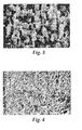
Fig. 4 is a scanning electron micrograph of an exemplary nanostructured polymeric film made according to one embodiment of the present invention Example 2; and -
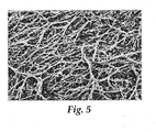
Fig. 5 is a scanning electron micrograph of an exemplary nanostructured polymeric film made according to one embodiment of the present invention Example 3. - As used herein, the term "aluminum" refers to aluminum and alloys of aluminum in which a majority by weight of the alloy is aluminum. Examples of other metals which may be present in such aluminum alloys are silicon, magnesium, bismuth, copper, nickel, zinc, chromium, lead, iron, titanium, and manganese.
- The tool has a porous surface (characterized by a network of pores) that is formed directly or indirectly by anodizing aluminum. For example, if the surface of the tool is aluminum, the porous surface may be formed directly by anodizing the surface of the tool.
- In one indirect method, a sacrificial metal (for example, copper) may be electroformed onto the anodized aluminum surface such that it forms a metal plate or foil with the inverse surface structure of the anodized aluminum. Subsequently the aluminum is dissolved, for example, by aqueous alkali, to leave the sacrificial metal plate or foil. Next, the desired metal (for example, nickel) is electroformed on the textured surface (that is, that surface having the inverse surface structure of the anodized aluminum) of the sacrificial metal plate or foil original anodized surface, followed by dissolving the sacrificial metal with a suitable etchant. Of course, other methods of replicating the anodized aluminum surface onto another metallic substrate may also be used.
- Conditions for anodizing aluminum are well known in the art, and generally involve applying a positive voltage to an aluminum workpiece in the presence of an appropriate oxidant such as, for example, sulfuric acid, oxalic acid, choric acid, boric acid, sulfonic acid, or the like. Further details of exemplary aluminum anodizing processes may be found in reference works such as, for example, the Aluminum Finishes Process Manual: Reynolds Metal Company, Richmond, Virginia, ©1973, pages 62-113.
- While the precise surface features may be varied depending on the anodizing conditions used, useful anodized aluminum surfaces have an average pore depth of from 0.1 to about 5 micrometers, and average pore widths in a range of from 10 to 500 nanometers.
- The tool may have any form suitable for embossing or solvent casting a film, including, for example, a roll, plate, belt, or sleeve.
- A continuous layer of thermoplastic polymer is formed on a portion of the porous surface of the tool such that the thermoplastic polymer fills the pores in that portion of the surface. The thermoplastic polymer may spontaneously flow into the pores, for example, if dissolved or dispersed in a solvent. In some cases, the thermoplastic polymer may be forced into the pores, by pressure, heat, or a combination of the two.
- The thermoplastic polymer should be selected such that it is not so sticky or brittle that it leaves material in the pores upon separation of the film from the tool. Useful thermoplastic polymers include cellulose esters (for example, cellulose acetate, cellulose butyrate), poly alpha-olefins (for example, polyethylene, polypropylene, and ethylenepropylene copolymers), and combinations thereof.
- The thermoplastic polymer may include additives such as stabilizers, anti-oxidants, fragrances, colorants, and the like, but conventional fillers should typically be avoided as their size interferes with formation of the nanofibrils.
- Using these thermoplastic polymers it is possible under normal conditions to obtain nanofibrils having an average width of from 10 to 200 nanometers and an aspect ratio of at least 10, 20, 30, 50, or more.
- Further, the density of the nanofibrils typically ranges from 1 to 500 per square micrometer, although higher and lower densities may also be obtained. In some embodiments, the nanofibrils are discrete and continuously extend away from the first surface of the film. In other embodiments, the nanofibrils are bonded to one another at points where they contact each other, and are generally disposed parallel to the first surface of the film.
- In order to obtain a clean release of the continuous layer from the porous surface of the tool, it is generally necessary to use a fluorinated organic release agent.
- In some embodiments, the surface of the tool may be treated with a fluorocarbon release agent. In some embodiments, fluorocarbon release agents are characterized by a polar group that bonds to the metal surface and a fluorinated segment having at least four -CF2- groups (for example, -CF2CF2CF2CF2- or -CF2CF2OCF2CF2-). Examples of useful fluorocarbon release agents include fluorocarbons having the trade designation "FLUORAD" (for example, "3M FLUORAD SURFACE MODIFIER") marketed by 3M Company, St. Paul, Minnesota; fluorochemical trichlorosilanes, and fluorochemical monophosphates, for example, as described in
U.S. Pat. Publ. No. 20040043146 (Pellerite et al. ); and fluorocarbon benzotriazoles as described inU. S. Pat. 6,376,065 (Korba et al. ). The fluorocarbon release agent may be applied to the porous surface, for example, as a solution or a vapor. Typically, the mold release is applied in sufficient quantity as to achieve at least monolayer coverage of the porous surface. - The fluorocarbon melt additive is combined with the thermoplastic polymer, such that the continuous layer comprises both thermoplastic polymer and the fluorocarbon melt additive. Suitable fluorocarbon release materials that may be combined with the thermoplastic polymer include, for example, fluorochemical oxazolidinones as described, for example, in
U. S. Pat. Nos. 5,025,052 (Crater et al.) and 5,099,026 (Crater et al. ); fluoroaliphatic group-containing non-ionic compounds as described, for example, inU. S. Pat. Nos. 5,244,951 (Gardiner ) and5,300,357 (Gardiner ); fluorochemical aminoalcohols as described, for example, inU. S. Pat. No. 5,380,778 (Buclcanin ); fluorochemical piperazine compounds as described, for example, inU. S. Pat. No. 5,451,622 (Boardman et al. ); fluorochemical and hydrocarbon surfactant blends as described, for example, inU. S. Pat. No. 5,804,625 (Temperante et al. ); fluoroaliphatic compounds as described, for example, inU. S. Pat. Nos. 5,882,762 (Goeman ),6,127,485 (Klun et al.) and 6,262,180 (Klun et al. ); fluorochemical oligomers as described, for example, inU. S. Pat. Nos. 6,174,964 (Jariwala et al.), 6,284,843 (Jariwala et al.), 6,288,157 (Jariwala et al.), 6,391,807 (Jariwala et al.) and 6,586,522 (Jariwala et al. ); and fluoroaliphatic radical-containing surface-modifying additives as described, for example, inU.S. Pat. No. 6,380,289 (Thompson et al. If used the level of fluorocarbon melt additives included with thermoplastic polymer in the continuous layer is typically in a level of from 0.01 to 10 percent based on the total weight of the continuous layer, although amounts outside this range may also be used. - Fluorocarbon release agents and fluorocarbon melt additives may be used in combination.
- The method of the present invention is better understood by reference to the Figures.
- In one exemplary method shown in
Fig. 1 , a film is embossed to generate nanofibrils. Referring now toFig. 1 , inexemplary method 100thermoplastic polymer film 150 is passed betweenbackup roll 110 andtool 120.Tool 120 hasporous surface 125 formed by anodic oxidation. Aspolymer film 150 is squeezed betweenbackup roll 110 andtool 120, it formscontinuous layer 130 such thatcontinuous layer 130 extends into the pores of thesurface 125. Upon emergence fromroll 110 andtool 120,film 140 is formed.Film 140 has first and second opposedmajor surfaces film 140 separates fromporous surface 125,nanofibrils 160 are formed that extend betweenporous surface 125 and firstmajor surface 145. Duringformation nanofibrils 160 stretch in length until they finally are released fromporous surface 125. - Typically, during such an embossing method, the thermoplastic polymer film should be heated to a temperature above the glass transition temperature of the thermoplastic polymer immediately prior to embossing.
- In another
exemplary method 200 shown inFig. 2 , moltenthermoplastic polymer 250 is passed betweenbackup roll 210 andtool 220.Tool 220 hasporous surface 225 formed by anodic oxidation. Asmolten polymer 250 is squeezed betweenbackup roll 210 andtool 220, it formscontinuous layer 230 such thatcontinuous layer 230 extends into the pores ofsurface 225. Upon emergence fromroll 210 andtool 220,molten polymer 250 is sufficiently cooled thatpolymer film 240 is formed.Film 240 has first and second opposedmajor surfaces film 240 separates fromporous surface 225,nanofibrils 260 are formed that extend betweenporous surface 225 and firstmajor surface 245. Duringformation nanofibrils 260 stretch in length until they finally are released fromporous surface 225. - The continuous film may also be formed by casting a solution of thermoplastic polymer onto a continuous belt or plate, removing the solvent, for example, by evaporation, and separating the continuous film from the tool to form a film having nanofibrils.
- While various peel angles may be used when separating the thermoplastic film from the tool, it has been found that peel angles of about 90 degrees reliably yield fibrils having high aspect ratio while still releasing from the porous surface, however other peel angles may also be used. In general, the peel rate should be adjusted to a sufficiently slow speed such that thermoplastic polymer does not remain in the pores of the tool. While wishing not to be bound by theory, the choice of peel rate is not believed to be important, as long as thermoplastic polymer does not remain in the pores of the tool.
- The output thermoplastic polymer film may have any thickness, width, and length. The film may be converted into strips, sheets, rolls, and the like.
- Methods according to the present invention may be practiced in step-wise or continuous manner.
- Films made according to the present invention have unique features that make them useful as substrates for display graphics, and in some cases for protective films.
- Objects and advantages of this invention are further illustrated by the following non-limiting examples, but the particular materials and amounts thereof recited in these examples, as well as other conditions and, details, should not be construed to unduly limit this invention.
- Unless otherwise noted, all parts, percentages, ratios, etc. in the examples and the rest of the specification are by weight, and all reagents used in the examples were obtained, or are available, from general chemical suppliers such as, for example, Sigma-Aldrich Company, Saint Louis, Missouri, or may be synthesized by conventional methods.
- Contact angles reported in the following examples were determined using deionized water at a temperature of 72°F (22°C).
- A piece of aluminum plate of dimensions 305 mm by 305 mm by 0.76 mm (composed of aluminum 1100 alloy and obtained from McMaster-Carr, Inc., Chicago Illinois) was cleaned using acetone and a paper towel to remove surface contaminants. The plate was placed in a tank containing 13 percent by weight of phosphoric acid and anodized in this solution at a temperature of 68° F (20° C) at a 60-volt electrical potential for 21.5 hours. The resulting anodized plate was removed from the tank, rinsed with deionized water and dried with compressed air.
- The anodized aluminum plate was then used as a template for replication by nickel electroforming as follows. In a polypropylene tank an electroforming solution was prepared that consisted of 600 g/L of nickel sulfamate, 30 g/L of boric acid and 0.3 g/L of lauryl sodium sulfate. The anodized aluminum plate was placed in the electroforming solution, and electroforming proceeded at 140° F (60° C) at a current density of 20 amp/ft2 (215.3 amp/m2) for 20 hours. The nickel deposited on the anodized aluminum plate had an average thickness of 0.508 mm. A 5 molar solution of sodium hydroxide was prepared and heated to 180° F (82° C). The anodized aluminum plate with the deposited nickel was then dipped in the sodium hydroxide solution until the nickel surface appeared completely black.
- The surface of the resulting nickel structure was examined with a scanning electron microscope (SEM) at a magnification of 80,000x, as shown in
Fig. 3 . The SEM showed that the aluminum had been completely dissolved, and that what remained was a nickel surface with nanostructures ranging in diameter from 10 to 230 am. - An anodized aluminum plate was prepared as in the first part of Example 1. A benzotriazole fluorochemical ester (0.1 percent by weight ester of benzotriazole-5-carbonxylic acid and 1H, 1H, 2H, 2H-perfluorododecyl alcohol, made by 3M Company, St. Paul, Minnesota and disclosed in
U. S. Pat. No. 6,376,065 (Korba et al. )) was used as a release agent. The release agent was applied as follows. A piece of filter paper (available from Whatman International, Ltd., Maidstone, England), having about the same dimensions as the anodized aluminum plate, was dipped into a tray containing the release agent until it was saturated and then positioned on top of the plate. The plate and filter paper were then placed in an oven set to a temperature of 120 °C. After 30 minutes the plate and filter paper were removed from the oven, the filter paper was lifted from the top of the plate and the plate was allowed to cool to room temperature. - A sheet of cellulose acetate (CAS No. 9004-35-7, available from SPI Supplies Division, West Chester, Pennsylvania), 25 micrometers in thickness, was placed on the anodized aluminum plate. Four drops of acetone were distributed on the surface of the cellulose acetate film using a 5 3/4 inch (14.6 cm) Pasteur pipette (available from VWR International, West Chester, Pennsylvania), thereby dissolving the film and allowing the cellulose acetate to flow into the porous anodized aluminum surface of the plate. After the acetone evaporated, the thin cellulose acetate film that remained was removed from the plate by peeling. First, the film was freed from the edges of the plate by lifting a corner of the film with tweezers, and pulling the film normal to the plate until the entire film released from the plate. Viewed via SEM at a magnification of 20,000x, as shown in
Fig. 4 , nanostructures were observed having aspect ratios ranging from about 10 to about 50. - Contact angles were measured for both the nanostructured cellulose acetate film of this example and a comparable unstructured cellulose acetate film. A goniometer obtained under the trade designation "MODEL A-100 GONIOMETER" from Ramé-Hart, Inc., Mountain Lakes, New Jersey, was used for the measurements. Both advancing and receding contact angles with deionized water were measured. For the nanostructured film of this example, the advancing angle was 61° and the receding angle was 0°. For a comparable unstructured cellulose acetate film, the advancing angle was 61° and the receding angle was 27°.
- An anodized aluminum plate was prepared as in the first part of Example 1, except that the electrical potential for anodizing was 70 volts and the time was 15 minutes. A polypropylene (available as PP3445 from Exxon Mobil Corporation, Irving TX) was combined with 1 percent of a fluorochemical additive (trade designation "FC1801", obtained from 3M Corporation, St. Paul, Minnesota) to make pellets. The pellets were formed into a film using thermal compression molding. The film was then embossed using the anodized aluminum plate as an embossing tool. A Wabash Compression Molding Machine, Model V75H-24-CLX (available from Wabash MPI, Wabash, IN) was used both to form the film and to emboss it. The film was embossed by applying a pressure of 1600 psi (11.03 MPa), at a temperature of 190° C for 3 minutes. When the embossed film had cooled to about 70° C, it was separated from the embossing tool as in Example 2. An SEM photomicrograph at a magnification of 15,000, shown in
Fig. 5 of the resulting embossed surface structure in the polypropylene film. - Contact angles were measured as in Example 2. For the embossed polypropylene film of this example, using deionized water, the advancing contact angle was 167° and the receding angle was 125°. For a comparable polypropylene film without the embossed nanostructure, the advancing contact angle was 104° and the receding angle was 78°.
- Various modifications and alterations of this invention may be made by those skilled in the art without departing from the scope and spirit of this invention, and it should be understood that this invention is not to be unduly limited to the illustrative embodiments set forth herein.
Claims (9)
- A method of making nanostructured polymeric film comprising:providing a tool having a porous anodized aluminum surface or a metallic replica thereof, wherein the average depth of the pores is in a range of from 0.1 micrometer to 5 micrometers and the average pore width is in a range of from 10 to 500 nanometers;forming a continuous layer of thermoplastic polymer on at least a portion of the surface of the tool such that the continuous layer extends into the pores of the surface, wherein the thermoplastic polymer is selected from cellulose esters, poly alpha-olefins, and combinations thereof; andseparating the continuous layer from the tool as a film having first and second opposed major surfaces with nanofibrils formed on the first major surface, the nanofibrils have an average width of from 5 to 200 nm and an aspect ratio of at least 10,wherein the continuous layer comprises a fluorocarbon melt additive.
- A method according to claim 1, wherein at least a portion of the nanofibrils are bonded to one another at points where they contact each other.
- A method according to claim 1, wherein the nanofibrils have distal portions oriented substantially parallel to the base.
- A method according to claim 1, wherein the thermoplastic polymer is selected from the group consisting of cellulose acetate, polyethylene and polypropylene.
- A method according to claim 1, wherein the continuous layer is formed by extrusion of molten thermoplastic polymer.
- A method according to claim 1, wherein the surface of the tool has a fluorocarbon release agent thereon.
- A method according to claim 1, wherein the surface of the tool has a fluorocarbon release agent thereon, and wherein the fluorocarbon release agent comprises a benzotriazole.
- A method according to claim 1, wherein the surface of the tool comprises anodized aluminum.
- A nanostructured polymeric film prepared according to the method of claim 1.
Applications Claiming Priority (2)
| Application Number | Priority Date | Filing Date | Title |
|---|---|---|---|
| US11/181,153 US7906057B2 (en) | 2005-07-14 | 2005-07-14 | Nanostructured article and method of making the same |
| PCT/US2006/027247 WO2007011663A1 (en) | 2005-07-14 | 2006-07-14 | Nanostructured article and method of making the same |
Publications (2)
| Publication Number | Publication Date |
|---|---|
| EP1910060A1 EP1910060A1 (en) | 2008-04-16 |
| EP1910060B1 true EP1910060B1 (en) | 2015-09-09 |
Family
ID=37441256
Family Applications (1)
| Application Number | Title | Priority Date | Filing Date |
|---|---|---|---|
| EP06787189.7A Not-in-force EP1910060B1 (en) | 2005-07-14 | 2006-07-14 | Nanostructured article and method of making the same |
Country Status (5)
| Country | Link |
|---|---|
| US (1) | US7906057B2 (en) |
| EP (1) | EP1910060B1 (en) |
| JP (1) | JP5307540B2 (en) |
| KR (1) | KR101354258B1 (en) |
| WO (1) | WO2007011663A1 (en) |
Families Citing this family (51)
| Publication number | Priority date | Publication date | Assignee | Title |
|---|---|---|---|---|
| US20060204720A1 (en) * | 2004-12-23 | 2006-09-14 | Biernath Rolf W | Uniaxially oriented birefringent article having a structured surface |
| US20060138705A1 (en) * | 2004-12-23 | 2006-06-29 | Korba Gary A | Method of making a structured surface article |
| US20060138686A1 (en) * | 2004-12-23 | 2006-06-29 | Ouderkirk Andrew J | Method of making a uniaxially stretched polymeric film having structured surface |
| US20060141220A1 (en) * | 2004-12-23 | 2006-06-29 | Merrill William W | Uniaxially oriented article having a structured surface |
| US20060141219A1 (en) * | 2004-12-23 | 2006-06-29 | Benson Olester Jr | Roll of a uniaxially oriented article having a structured surface |
| US20060138694A1 (en) * | 2004-12-23 | 2006-06-29 | Biernath Rolf W | Method of making a polymeric film having structured surfaces via replication |
| US20060282399A1 (en) * | 2005-05-09 | 2006-12-14 | Richard Ackermann | Digital sound recording personalized at a time and place remote from initial delivery to a retail customer |
| US9134471B2 (en) * | 2006-06-28 | 2015-09-15 | 3M Innovative Properties Company | Oriented polymeric articles and method |
| WO2008004827A1 (en) * | 2006-07-05 | 2008-01-10 | Postech Academy-Industry Foundation | Method for fabricating superhydrophobic surface and solid having superhydrophobic surface structure by the same method |
| US8202765B2 (en) * | 2009-01-22 | 2012-06-19 | International Business Machines Corporation | Achieving mechanical and thermal stability in a multi-chip package |
| US20100252961A1 (en) * | 2009-04-06 | 2010-10-07 | 3M Innovative Properties Company | Optical film replication on low thermal diffusivity tooling with conformal coating |
| WO2010148322A1 (en) | 2009-06-19 | 2010-12-23 | Under Armour, Inc. | Nanoadhesion structures for sporting gear |
| US8524134B2 (en) * | 2010-07-12 | 2013-09-03 | Graham J. Hubbard | Method of molding polymeric materials to impart a desired texture thereto |
| CN103370174B (en) | 2010-12-31 | 2017-03-29 | 圣戈本陶瓷及塑料股份有限公司 | The forming method of the abrasive grains with given shape and such particle |
| WO2012094604A2 (en) * | 2011-01-06 | 2012-07-12 | Purdue Research Foundation | Large strain extrusion machining processes and bulk forms produced therefrom |
| US8840694B2 (en) | 2011-06-30 | 2014-09-23 | Saint-Gobain Ceramics & Plastics, Inc. | Liquid phase sintered silicon carbide abrasive particles |
| WO2013003830A2 (en) | 2011-06-30 | 2013-01-03 | Saint-Gobain Ceramics & Plastics, Inc. | Abrasive articles including abrasive particles of silicon nitride |
| JP5802336B2 (en) | 2011-09-26 | 2015-10-28 | サン−ゴバン セラミックス アンド プラスティクス,インコーポレイティド | Abrasive product comprising abrasive particle material, abrasive cloth paper using the abrasive particle material, and forming method |
| CA2862453A1 (en) | 2011-12-30 | 2013-07-04 | Saint-Gobain Ceramics & Plastics, Inc. | Forming shaped abrasive particles |
| KR101681526B1 (en) | 2011-12-30 | 2016-12-01 | 생-고뱅 세라믹스 앤드 플라스틱스, 인코포레이티드 | Composite shaped abrasive particles and method of forming same |
| JP6033886B2 (en) | 2011-12-30 | 2016-11-30 | サン−ゴバン セラミックス アンド プラスティクス,インコーポレイティド | Shaped abrasive particles and method for forming the same |
| US8840696B2 (en) | 2012-01-10 | 2014-09-23 | Saint-Gobain Ceramics & Plastics, Inc. | Abrasive particles having particular shapes and methods of forming such particles |
| BR112014017050B1 (en) | 2012-01-10 | 2021-05-11 | Saint-Gobain Ceramics & Plastics, Inc. | molded abrasive particle |
| WO2013149209A1 (en) | 2012-03-30 | 2013-10-03 | Saint-Gobain Abrasives, Inc. | Abrasive products having fibrillated fibers |
| US9200187B2 (en) | 2012-05-23 | 2015-12-01 | Saint-Gobain Ceramics & Plastics, Inc. | Shaped abrasive particles and methods of forming same |
| EP2866977B8 (en) | 2012-06-29 | 2023-01-18 | Saint-Gobain Ceramics & Plastics, Inc. | Abrasive particles having particular shapes and methods of forming such particles |
| EP2906392A4 (en) | 2012-10-15 | 2016-07-13 | Saint Gobain Abrasives Inc | Abrasive particles having particular shapes and methods of forming such particles |
| EP2938459B1 (en) | 2012-12-31 | 2021-06-16 | Saint-Gobain Ceramics & Plastics, Inc. | Particulate materials and methods of forming same |
| EP2978566A4 (en) | 2013-03-29 | 2017-01-25 | Saint-Gobain Abrasives, Inc. | Abrasive particles having particular shapes and methods of forming such particles |
| TW201502263A (en) | 2013-06-28 | 2015-01-16 | Saint Gobain Ceramics | Abrasive article including shaped abrasive particles |
| AU2014324453B2 (en) | 2013-09-30 | 2017-08-03 | Saint-Gobain Ceramics & Plastics, Inc. | Shaped abrasive particles and methods of forming same |
| JP6290428B2 (en) | 2013-12-31 | 2018-03-07 | サンーゴバン アブレイシブズ,インコーポレイティド | Abrasive articles containing shaped abrasive particles |
| US9771507B2 (en) | 2014-01-31 | 2017-09-26 | Saint-Gobain Ceramics & Plastics, Inc. | Shaped abrasive particle including dopant material and method of forming same |
| WO2015144174A1 (en) * | 2014-03-24 | 2015-10-01 | Inmold A/S | Method and apparatus for producing a high aspect ratio nanostructured foil by extrusion coating or extrusion casting |
| KR101884178B1 (en) | 2014-04-14 | 2018-08-02 | 생-고뱅 세라믹스 앤드 플라스틱스, 인코포레이티드 | Abrasive article including shaped abrasive particles |
| CN111331524B (en) | 2014-04-14 | 2022-04-29 | 圣戈本陶瓷及塑料股份有限公司 | Abrasive article including shaped abrasive particles |
| WO2015184355A1 (en) | 2014-05-30 | 2015-12-03 | Saint-Gobain Abrasives, Inc. | Method of using an abrasive article including shaped abrasive particles |
| EP3230041A1 (en) | 2014-12-10 | 2017-10-18 | Inmold A/S | Method and apparatus for producing a nanostructured or microstructured foil by extrusion coating or extrusion casting |
| US9707529B2 (en) | 2014-12-23 | 2017-07-18 | Saint-Gobain Ceramics & Plastics, Inc. | Composite shaped abrasive particles and method of forming same |
| US9914864B2 (en) | 2014-12-23 | 2018-03-13 | Saint-Gobain Ceramics & Plastics, Inc. | Shaped abrasive particles and method of forming same |
| US9676981B2 (en) | 2014-12-24 | 2017-06-13 | Saint-Gobain Ceramics & Plastics, Inc. | Shaped abrasive particle fractions and method of forming same |
| CN107636109A (en) | 2015-03-31 | 2018-01-26 | 圣戈班磨料磨具有限公司 | Fixed abrasive articles and its forming method |
| TWI634200B (en) | 2015-03-31 | 2018-09-01 | 聖高拜磨料有限公司 | Fixed abrasive articles and methods of forming same |
| PL3307483T3 (en) | 2015-06-11 | 2020-11-16 | Saint-Gobain Ceramics&Plastics, Inc. | Abrasive article including shaped abrasive particles |
| EP3455321B1 (en) | 2016-05-10 | 2022-04-20 | Saint-Gobain Ceramics&Plastics, Inc. | Methods of forming abrasive particles |
| WO2018064642A1 (en) | 2016-09-29 | 2018-04-05 | Saint-Gobain Abrasives, Inc. | Fixed abrasive articles and methods of forming same |
| US10759024B2 (en) | 2017-01-31 | 2020-09-01 | Saint-Gobain Ceramics & Plastics, Inc. | Abrasive article including shaped abrasive particles |
| US10563105B2 (en) | 2017-01-31 | 2020-02-18 | Saint-Gobain Ceramics & Plastics, Inc. | Abrasive article including shaped abrasive particles |
| US10865148B2 (en) | 2017-06-21 | 2020-12-15 | Saint-Gobain Ceramics & Plastics, Inc. | Particulate materials and methods of forming same |
| WO2019159792A1 (en) * | 2018-02-16 | 2019-08-22 | 東レ株式会社 | Resin structure and method for manufacturing resin structure |
| CN114867582A (en) | 2019-12-27 | 2022-08-05 | 圣戈本陶瓷及塑料股份有限公司 | Abrasive article and method of forming the same |
Family Cites Families (72)
| Publication number | Priority date | Publication date | Assignee | Title |
|---|---|---|---|---|
| US3927692A (en) | 1974-06-28 | 1975-12-23 | American Standard Inc | Four-way poppet valve device |
| US4674878A (en) | 1985-05-09 | 1987-06-23 | The United States Of America As Represented By The United States Department Of Energy | Practical substrate and apparatus for static and continuous monitoring by surface-enhanced raman spectroscopy |
| US5039561A (en) | 1986-08-25 | 1991-08-13 | Minnesota Mining And Manufacturing Company | Method for preparing an article having surface layer of uniformly oriented, crystalline, organic microstructures |
| US5025052A (en) | 1986-09-12 | 1991-06-18 | Minnesota Mining And Manufacturing Company | Fluorochemical oxazolidinones |
| US5099026A (en) | 1986-09-12 | 1992-03-24 | Crater Davis H | Fluorochemical oxazolidinones |
| US4781952A (en) | 1987-03-13 | 1988-11-01 | The D. L. Auld Company | Decorative article and process for making |
| JPH0344496A (en) * | 1989-07-11 | 1991-02-26 | Furukawa Alum Co Ltd | Aluminum or aluminum alloy material having superior adhesion to coating film and production thereof |
| US5017007A (en) | 1989-07-27 | 1991-05-21 | Milne Christopher G | Apparatus and microbase for surface-enhanced raman spectroscopy system and method for producing same |
| AU8282691A (en) | 1990-07-20 | 1992-02-18 | McGrew, Steven P. | Embossing tool |
| US5244951A (en) | 1991-05-02 | 1993-09-14 | Minnesota Mining And Manufacturing Company | Durably hydrophilic, thermoplastic fiber |
| JPH0525696A (en) | 1991-07-17 | 1993-02-02 | Mazda Motor Corp | Al alloy member and production thereof |
| US5380778A (en) | 1992-09-30 | 1995-01-10 | Minnesota Mining And Manufacturing Company | Fluorochemical aminoalcohols |
| US5451622A (en) | 1992-09-30 | 1995-09-19 | Minnesota Mining And Manufacturing Company | Composition comprising thermoplastic polymer and fluorochemical piperazine compound |
| US5300263A (en) | 1992-10-28 | 1994-04-05 | Minnesota Mining And Manufacturing Company | Method of making a microlens array and mold |
| EP0702610B1 (en) | 1993-06-11 | 1997-05-28 | Minnesota Mining And Manufacturing Company | Laser machined replication tooling |
| US6380289B1 (en) | 1993-06-28 | 2002-04-30 | 3M Innovative Properties Company | Thermoplastic composition comprising fluoroaliphatic radical-containing surface-modifying additive |
| AU679968B2 (en) | 1993-09-13 | 1997-07-17 | Minnesota Mining And Manufacturing Company | Abrasive article, method of manufacture of same, method of using same for finishing, and a production tool |
| US5674592A (en) | 1995-05-04 | 1997-10-07 | Minnesota Mining And Manufacturing Company | Functionalized nanostructured films |
| US5659408A (en) | 1995-05-24 | 1997-08-19 | Polaroid Corporation | Reflective image-providing display viewed with holographically diffused ambient light |
| JPH09155972A (en) * | 1995-12-12 | 1997-06-17 | Ykk Corp | Water repellant film and its manufacture |
| AU717090B2 (en) | 1996-03-07 | 2000-03-16 | Minnesota Mining And Manufacturing Company | Carpet yarn having high soil resistance |
| US5805338A (en) | 1996-04-10 | 1998-09-08 | Minnesota Minning And Manufacturing Company | Pillowed flexible cube-corner sheeting and methods of manufacture |
| US5751415A (en) | 1996-05-13 | 1998-05-12 | Process Instruments, Inc. | Raman spectroscopy apparatus and method for continuous chemical analysis of fluid streams |
| US5804625A (en) | 1996-05-21 | 1998-09-08 | Minnesota Mining And Manufacturing Company | Fluorochemical and hydrocarbon surfactant blends as hydrophilic additives to thermoplastic polymers |
| JP3645985B2 (en) * | 1997-03-07 | 2005-05-11 | 昭 藤嶋 | Deodorizing and deodorizing material and method for producing the same |
| US6127485A (en) | 1997-07-28 | 2000-10-03 | 3M Innovative Properties Company | High temperature-stable fluorochemicals as hydrophobic and oleophobic additives to synthetic organic polymers |
| DE69815130T2 (en) | 1997-10-01 | 2004-04-08 | Minnesota Mining And Mfg. Co., Saint Paul | EMBOSSED ORIENTED POLYMER FILMS |
| CN1132821C (en) | 1998-01-27 | 2003-12-31 | 美国3M公司 | Fluorochemical Benzotriazoles |
| IL124598A (en) | 1998-05-21 | 2001-10-31 | Ophir Optronics Ltd | Precision double-sided aspheric elements |
| DE19825984C1 (en) | 1998-06-10 | 2000-03-16 | Fraunhofer Ges Forschung | Process for the production of thermotropic cast resin systems and its use |
| US6190594B1 (en) | 1999-03-01 | 2001-02-20 | 3M Innovative Properties Company | Tooling for articles with structured surfaces |
| US6391807B1 (en) | 1999-09-24 | 2002-05-21 | 3M Innovative Properties Company | Polymer composition containing a fluorochemical oligomer |
| US6288157B1 (en) | 1999-05-11 | 2001-09-11 | 3M Innovative Properties Company | Alkylated fluorochemical oligomers and use thereof |
| WO2000073082A1 (en) | 1999-06-01 | 2000-12-07 | 3M Innovative Properties Company | Random microembossed receptor media |
| JP3938640B2 (en) | 1999-07-07 | 2007-06-27 | 富士フイルム株式会社 | Solution casting method |
| JP4010081B2 (en) * | 1999-08-18 | 2007-11-21 | コニカミノルタホールディングス株式会社 | Cellulose ester and polarizing plate protective film using the same |
| US6174964B1 (en) | 1999-09-24 | 2001-01-16 | 3M Innovative Properties Company | Fluorochemical oligomer and use thereof |
| US6737160B1 (en) | 1999-12-20 | 2004-05-18 | The Regents Of The University Of California | Adhesive microstructure and method of forming same |
| US6592988B1 (en) * | 1999-12-29 | 2003-07-15 | 3M Innovative Properties Company | Water-and oil-repellent, antistatic composition |
| EP1180480B1 (en) | 2000-01-26 | 2012-11-14 | Dai Nippon Printing Co., Ltd. | Heat-sealing method |
| US6641767B2 (en) | 2000-03-10 | 2003-11-04 | 3M Innovative Properties Company | Methods for replication, replicated articles, and replication tools |
| DE10015931A1 (en) | 2000-03-30 | 2001-10-04 | Schimmel Thomas | Process for electrochemical nanostructuring |
| KR20030001493A (en) | 2000-05-16 | 2003-01-06 | 쓰리엠 이노베이티브 프로퍼티즈 캄파니 | Holographic reflector |
| US6586522B1 (en) | 2000-06-12 | 2003-07-01 | 3M Innovative Properties Company | Water- and oil-repellent composition |
| US6468451B1 (en) | 2000-06-23 | 2002-10-22 | 3M Innovative Properties Company | Method of making a fibrillated article |
| JP3831186B2 (en) * | 2000-09-08 | 2006-10-11 | 本田技研工業株式会社 | Motorcycle storage box structure |
| US6632872B1 (en) | 2000-09-19 | 2003-10-14 | 3M Innovative Properties Company | Adhesive compositions including self-assembling molecules, adhesives, articles, and methods |
| DE10062203A1 (en) | 2000-12-13 | 2002-06-20 | Creavis Tech & Innovation Gmbh | Metallic embossing tool or embossing roller, used for embossing hydrophobic polymers to provide a surface structure to the polymer, is rendered hydrophobic before the first embossing step |
| DE10064520A1 (en) | 2000-12-22 | 2002-07-04 | Daimler Chrysler Ag | Method for producing structured surface with self-cleaning effect on vehicles, comprises producing micro- or nano-structure on carrier by anodic oxidation and transferring this structure to the surface |
| JP2002212787A (en) * | 2001-01-12 | 2002-07-31 | Kobe Steel Ltd | HIGHLY CORROSION RESISTING Al ALLOY MEMBER AND PRODUCTION METHOD THEREFOR |
| US6852266B2 (en) | 2001-01-19 | 2005-02-08 | Korry Electronics Co. | Ultrasonic assisted deposition of anti-stick films on metal oxides |
| US6527991B1 (en) | 2001-04-11 | 2003-03-04 | Rbx Industries, Inc. | Method for embossing a foam article |
| US6576887B2 (en) | 2001-08-15 | 2003-06-10 | 3M Innovative Properties Company | Light guide for use with backlit display |
| US6977113B2 (en) | 2001-10-09 | 2005-12-20 | 3M Innovative Properties Company | Microfiber articles from multi-layer substrates |
| JP2003124491A (en) * | 2001-10-15 | 2003-04-25 | Sharp Corp | Thin film solar cell module |
| DE10158347A1 (en) | 2001-11-28 | 2003-06-12 | Tesa Ag | Process for the production of nano- and micro-structured polymer films |
| CN1445385A (en) | 2002-03-14 | 2003-10-01 | 中国科学院化学研究所 | Method for forming super hydrophilic film on metal board |
| US6824378B2 (en) | 2002-05-31 | 2004-11-30 | 3M Innovative Properties Company | Microreplication tool with gas release features |
| US7105809B2 (en) | 2002-11-18 | 2006-09-12 | 3M Innovative Properties Company | Microstructured polymeric substrate |
| US6823653B1 (en) | 2003-03-03 | 2004-11-30 | Patricia A. Stark | Sanitary precision polymer film casting and dispersion injection system |
| JP4406553B2 (en) * | 2003-11-21 | 2010-01-27 | 財団法人神奈川科学技術アカデミー | Method for manufacturing antireflection film |
| US7019346B2 (en) | 2003-12-23 | 2006-03-28 | Intel Corporation | Capacitor having an anodic metal oxide substrate |
| JP4466074B2 (en) * | 2003-12-26 | 2010-05-26 | 株式会社日立製作所 | Fine metal structure and manufacturing method thereof, and fine mold and device |
| JP2006062049A (en) * | 2004-08-30 | 2006-03-09 | Kanagawa Acad Of Sci & Technol | Nanopillar structure and its manufacturing method, and device for separation and its manufacturing method |
| US20060138705A1 (en) | 2004-12-23 | 2006-06-29 | Korba Gary A | Method of making a structured surface article |
| US20060138694A1 (en) | 2004-12-23 | 2006-06-29 | Biernath Rolf W | Method of making a polymeric film having structured surfaces via replication |
| US20060138686A1 (en) | 2004-12-23 | 2006-06-29 | Ouderkirk Andrew J | Method of making a uniaxially stretched polymeric film having structured surface |
| US20060204720A1 (en) | 2004-12-23 | 2006-09-14 | Biernath Rolf W | Uniaxially oriented birefringent article having a structured surface |
| US20060141218A1 (en) | 2004-12-23 | 2006-06-29 | Biernath Rolf W | Uniaxially oriented articles having structured surface |
| US20060141219A1 (en) | 2004-12-23 | 2006-06-29 | Benson Olester Jr | Roll of a uniaxially oriented article having a structured surface |
| US20060141220A1 (en) | 2004-12-23 | 2006-06-29 | Merrill William W | Uniaxially oriented article having a structured surface |
| US7767273B2 (en) * | 2005-03-09 | 2010-08-03 | 3M Innovative Properties Company | Apparatus and method for producing two-sided patterned web in registration |
-
2005
- 2005-07-14 US US11/181,153 patent/US7906057B2/en not_active Expired - Fee Related
-
2006
- 2006-07-14 EP EP06787189.7A patent/EP1910060B1/en not_active Not-in-force
- 2006-07-14 WO PCT/US2006/027247 patent/WO2007011663A1/en active Application Filing
- 2006-07-14 JP JP2008521616A patent/JP5307540B2/en not_active Expired - Fee Related
- 2006-07-14 KR KR1020087000997A patent/KR101354258B1/en not_active IP Right Cessation
Also Published As
| Publication number | Publication date |
|---|---|
| EP1910060A1 (en) | 2008-04-16 |
| US20070013103A1 (en) | 2007-01-18 |
| US7906057B2 (en) | 2011-03-15 |
| WO2007011663A1 (en) | 2007-01-25 |
| KR101354258B1 (en) | 2014-01-22 |
| KR20080023256A (en) | 2008-03-12 |
| JP5307540B2 (en) | 2013-10-02 |
| JP2009501811A (en) | 2009-01-22 |
Similar Documents
| Publication | Publication Date | Title |
|---|---|---|
| EP1910060B1 (en) | Nanostructured article and method of making the same | |
| Saji | Superhydrophobic surfaces and coatings by electrochemical anodic oxidation and plasma electrolytic oxidation | |
| CA2800381C (en) | Articles with super-hydrophobic and/or self-cleaning surfaces and method of making same | |
| CA3122949C (en) | Method for manufacturing aluminum alloy anodized film having superhydrophobic surface | |
| JP2009501811A5 (en) | ||
| US20030157347A1 (en) | Methods for replication, replicated articles, and replication tools | |
| CN103521929A (en) | Metal die for coining super-hydrophobic micro-nanometer surface and laser manufacturing method thereof | |
| KR101873096B1 (en) | Nanotextured superhydrophobic polymer film and method of manufacturing the same | |
| Koponen et al. | Modification of cycloolefin copolymer and poly (vinyl chloride) surfaces by superimposition of nano-and microstructures | |
| JP2015071826A (en) | Aluminum surface treatment method, and aluminum surface treatment material | |
| JP2018206910A (en) | Electrode material for aluminum electrolytic capacitor, and method for manufacturing the same | |
| Zhan et al. | Robust mold fabricated by femtosecond laser pulses for continuous thermal imprinting of superhydrophobic surfaces | |
| JP2012020580A (en) | Material and method to produce desired image drum surface topography for solid ink jet | |
| JPWO2016136804A1 (en) | Electrode material for aluminum electrolytic capacitor and method for producing the same | |
| CN110241450B (en) | Porous anodic alumina template and preparation method and application thereof | |
| Ramana Reddy et al. | Contact angle measurement studies on porous anodic alumina membranes prepared using different electrolytes | |
| Schmid et al. | Nanostructured surfaces of metals and polymers by imprinting with nanoporous alumina | |
| Navas et al. | Titanium nitride stamps replicating nanoporous anodic alumina films | |
| KR102179027B1 (en) | Method for manufacturing alloy for superhydrophobic pipes using anodizing | |
| TWI672398B (en) | Amphiphobic structure and method for manufacturing the same | |
| Vojkuvka et al. | Study of porous alumina porosity after pore widening process | |
| JP4321105B2 (en) | Polylactic acid film | |
| JP2017100324A (en) | Laminate structure and method for producing the same | |
| JP3952595B2 (en) | High sensitivity heat sensitive stencil film | |
| Kumar et al. | Influence of Various Electrolytes on Surface Morphology of AAO–A Brief Review |
Legal Events
| Date | Code | Title | Description |
|---|---|---|---|
| PUAI | Public reference made under article 153(3) epc to a published international application that has entered the european phase |
Free format text: ORIGINAL CODE: 0009012 |
|
| 17P | Request for examination filed |
Effective date: 20080123 |
|
| AK | Designated contracting states |
Kind code of ref document: A1 Designated state(s): AT BE BG CH CY CZ DE DK EE ES FI FR GB GR HU IE IS IT LI LT LU LV MC NL PL PT RO SE SI SK TR |
|
| 17Q | First examination report despatched |
Effective date: 20090327 |
|
| DAX | Request for extension of the european patent (deleted) | ||
| GRAP | Despatch of communication of intention to grant a patent |
Free format text: ORIGINAL CODE: EPIDOSNIGR1 |
|
| INTG | Intention to grant announced |
Effective date: 20150402 |
|
| GRAS | Grant fee paid |
Free format text: ORIGINAL CODE: EPIDOSNIGR3 |
|
| GRAA | (expected) grant |
Free format text: ORIGINAL CODE: 0009210 |
|
| AK | Designated contracting states |
Kind code of ref document: B1 Designated state(s): AT BE BG CH CY CZ DE DK EE ES FI FR GB GR HU IE IS IT LI LT LU LV MC NL PL PT RO SE SI SK TR |
|
| REG | Reference to a national code |
Ref country code: GB Ref legal event code: FG4D |
|
| REG | Reference to a national code |
Ref country code: AT Ref legal event code: REF Ref document number: 747769 Country of ref document: AT Kind code of ref document: T Effective date: 20150915 Ref country code: CH Ref legal event code: EP |
|
| REG | Reference to a national code |
Ref country code: IE Ref legal event code: FG4D |
|
| REG | Reference to a national code |
Ref country code: DE Ref legal event code: R096 Ref document number: 602006046604 Country of ref document: DE |
|
| REG | Reference to a national code |
Ref country code: NL Ref legal event code: MP Effective date: 20150909 |
|
| PG25 | Lapsed in a contracting state [announced via postgrant information from national office to epo] |
Ref country code: GR Free format text: LAPSE BECAUSE OF FAILURE TO SUBMIT A TRANSLATION OF THE DESCRIPTION OR TO PAY THE FEE WITHIN THE PRESCRIBED TIME-LIMIT Effective date: 20151210 Ref country code: FI Free format text: LAPSE BECAUSE OF FAILURE TO SUBMIT A TRANSLATION OF THE DESCRIPTION OR TO PAY THE FEE WITHIN THE PRESCRIBED TIME-LIMIT Effective date: 20150909 Ref country code: LV Free format text: LAPSE BECAUSE OF FAILURE TO SUBMIT A TRANSLATION OF THE DESCRIPTION OR TO PAY THE FEE WITHIN THE PRESCRIBED TIME-LIMIT Effective date: 20150909 Ref country code: LT Free format text: LAPSE BECAUSE OF FAILURE TO SUBMIT A TRANSLATION OF THE DESCRIPTION OR TO PAY THE FEE WITHIN THE PRESCRIBED TIME-LIMIT Effective date: 20150909 |
|
| REG | Reference to a national code |
Ref country code: LT Ref legal event code: MG4D |
|
| REG | Reference to a national code |
Ref country code: AT Ref legal event code: MK05 Ref document number: 747769 Country of ref document: AT Kind code of ref document: T Effective date: 20150909 |
|
| PG25 | Lapsed in a contracting state [announced via postgrant information from national office to epo] |
Ref country code: ES Free format text: LAPSE BECAUSE OF FAILURE TO SUBMIT A TRANSLATION OF THE DESCRIPTION OR TO PAY THE FEE WITHIN THE PRESCRIBED TIME-LIMIT Effective date: 20150909 Ref country code: SE Free format text: LAPSE BECAUSE OF FAILURE TO SUBMIT A TRANSLATION OF THE DESCRIPTION OR TO PAY THE FEE WITHIN THE PRESCRIBED TIME-LIMIT Effective date: 20150909 |
|
| PG25 | Lapsed in a contracting state [announced via postgrant information from national office to epo] |
Ref country code: NL Free format text: LAPSE BECAUSE OF FAILURE TO SUBMIT A TRANSLATION OF THE DESCRIPTION OR TO PAY THE FEE WITHIN THE PRESCRIBED TIME-LIMIT Effective date: 20150909 |
|
| PG25 | Lapsed in a contracting state [announced via postgrant information from national office to epo] |
Ref country code: CZ Free format text: LAPSE BECAUSE OF FAILURE TO SUBMIT A TRANSLATION OF THE DESCRIPTION OR TO PAY THE FEE WITHIN THE PRESCRIBED TIME-LIMIT Effective date: 20150909 Ref country code: EE Free format text: LAPSE BECAUSE OF FAILURE TO SUBMIT A TRANSLATION OF THE DESCRIPTION OR TO PAY THE FEE WITHIN THE PRESCRIBED TIME-LIMIT Effective date: 20150909 Ref country code: SK Free format text: LAPSE BECAUSE OF FAILURE TO SUBMIT A TRANSLATION OF THE DESCRIPTION OR TO PAY THE FEE WITHIN THE PRESCRIBED TIME-LIMIT Effective date: 20150909 Ref country code: IT Free format text: LAPSE BECAUSE OF FAILURE TO SUBMIT A TRANSLATION OF THE DESCRIPTION OR TO PAY THE FEE WITHIN THE PRESCRIBED TIME-LIMIT Effective date: 20150909 Ref country code: IS Free format text: LAPSE BECAUSE OF FAILURE TO SUBMIT A TRANSLATION OF THE DESCRIPTION OR TO PAY THE FEE WITHIN THE PRESCRIBED TIME-LIMIT Effective date: 20160109 |
|
| PG25 | Lapsed in a contracting state [announced via postgrant information from national office to epo] |
Ref country code: RO Free format text: LAPSE BECAUSE OF FAILURE TO SUBMIT A TRANSLATION OF THE DESCRIPTION OR TO PAY THE FEE WITHIN THE PRESCRIBED TIME-LIMIT Effective date: 20150909 Ref country code: PT Free format text: LAPSE BECAUSE OF FAILURE TO SUBMIT A TRANSLATION OF THE DESCRIPTION OR TO PAY THE FEE WITHIN THE PRESCRIBED TIME-LIMIT Effective date: 20160111 Ref country code: PL Free format text: LAPSE BECAUSE OF FAILURE TO SUBMIT A TRANSLATION OF THE DESCRIPTION OR TO PAY THE FEE WITHIN THE PRESCRIBED TIME-LIMIT Effective date: 20150909 Ref country code: AT Free format text: LAPSE BECAUSE OF FAILURE TO SUBMIT A TRANSLATION OF THE DESCRIPTION OR TO PAY THE FEE WITHIN THE PRESCRIBED TIME-LIMIT Effective date: 20150909 |
|
| REG | Reference to a national code |
Ref country code: DE Ref legal event code: R097 Ref document number: 602006046604 Country of ref document: DE |
|
| PLBE | No opposition filed within time limit |
Free format text: ORIGINAL CODE: 0009261 |
|
| STAA | Information on the status of an ep patent application or granted ep patent |
Free format text: STATUS: NO OPPOSITION FILED WITHIN TIME LIMIT |
|
| 26N | No opposition filed |
Effective date: 20160610 |
|
| PG25 | Lapsed in a contracting state [announced via postgrant information from national office to epo] |
Ref country code: SI Free format text: LAPSE BECAUSE OF FAILURE TO SUBMIT A TRANSLATION OF THE DESCRIPTION OR TO PAY THE FEE WITHIN THE PRESCRIBED TIME-LIMIT Effective date: 20150909 Ref country code: DK Free format text: LAPSE BECAUSE OF FAILURE TO SUBMIT A TRANSLATION OF THE DESCRIPTION OR TO PAY THE FEE WITHIN THE PRESCRIBED TIME-LIMIT Effective date: 20150909 |
|
| PG25 | Lapsed in a contracting state [announced via postgrant information from national office to epo] |
Ref country code: BE Free format text: LAPSE BECAUSE OF FAILURE TO SUBMIT A TRANSLATION OF THE DESCRIPTION OR TO PAY THE FEE WITHIN THE PRESCRIBED TIME-LIMIT Effective date: 20150909 |
|
| REG | Reference to a national code |
Ref country code: CH Ref legal event code: PL |
|
| GBPC | Gb: european patent ceased through non-payment of renewal fee |
Effective date: 20160714 |
|
| PG25 | Lapsed in a contracting state [announced via postgrant information from national office to epo] |
Ref country code: MC Free format text: LAPSE BECAUSE OF FAILURE TO SUBMIT A TRANSLATION OF THE DESCRIPTION OR TO PAY THE FEE WITHIN THE PRESCRIBED TIME-LIMIT Effective date: 20150909 |
|
| PG25 | Lapsed in a contracting state [announced via postgrant information from national office to epo] |
Ref country code: CH Free format text: LAPSE BECAUSE OF NON-PAYMENT OF DUE FEES Effective date: 20160731 Ref country code: LI Free format text: LAPSE BECAUSE OF NON-PAYMENT OF DUE FEES Effective date: 20160731 Ref country code: FR Free format text: LAPSE BECAUSE OF NON-PAYMENT OF DUE FEES Effective date: 20160801 |
|
| REG | Reference to a national code |
Ref country code: FR Ref legal event code: ST Effective date: 20170331 |
|
| REG | Reference to a national code |
Ref country code: IE Ref legal event code: MM4A |
|
| PG25 | Lapsed in a contracting state [announced via postgrant information from national office to epo] |
Ref country code: GB Free format text: LAPSE BECAUSE OF NON-PAYMENT OF DUE FEES Effective date: 20160714 |
|
| PG25 | Lapsed in a contracting state [announced via postgrant information from national office to epo] |
Ref country code: IE Free format text: LAPSE BECAUSE OF NON-PAYMENT OF DUE FEES Effective date: 20160714 |
|
| PG25 | Lapsed in a contracting state [announced via postgrant information from national office to epo] |
Ref country code: LU Free format text: LAPSE BECAUSE OF NON-PAYMENT OF DUE FEES Effective date: 20160714 |
|
| PG25 | Lapsed in a contracting state [announced via postgrant information from national office to epo] |
Ref country code: CY Free format text: LAPSE BECAUSE OF FAILURE TO SUBMIT A TRANSLATION OF THE DESCRIPTION OR TO PAY THE FEE WITHIN THE PRESCRIBED TIME-LIMIT Effective date: 20150909 Ref country code: HU Free format text: LAPSE BECAUSE OF FAILURE TO SUBMIT A TRANSLATION OF THE DESCRIPTION OR TO PAY THE FEE WITHIN THE PRESCRIBED TIME-LIMIT; INVALID AB INITIO Effective date: 20060714 |
|
| PG25 | Lapsed in a contracting state [announced via postgrant information from national office to epo] |
Ref country code: TR Free format text: LAPSE BECAUSE OF FAILURE TO SUBMIT A TRANSLATION OF THE DESCRIPTION OR TO PAY THE FEE WITHIN THE PRESCRIBED TIME-LIMIT Effective date: 20150909 |
|
| PG25 | Lapsed in a contracting state [announced via postgrant information from national office to epo] |
Ref country code: BG Free format text: LAPSE BECAUSE OF FAILURE TO SUBMIT A TRANSLATION OF THE DESCRIPTION OR TO PAY THE FEE WITHIN THE PRESCRIBED TIME-LIMIT Effective date: 20150909 |
|
| PGFP | Annual fee paid to national office [announced via postgrant information from national office to epo] |
Ref country code: DE Payment date: 20190702 Year of fee payment: 14 |
|
| REG | Reference to a national code |
Ref country code: DE Ref legal event code: R119 Ref document number: 602006046604 Country of ref document: DE |
|
| PG25 | Lapsed in a contracting state [announced via postgrant information from national office to epo] |
Ref country code: DE Free format text: LAPSE BECAUSE OF NON-PAYMENT OF DUE FEES Effective date: 20210202 |